DESIGNING AND FABRICATION MODULAR PRODUCT WITH THE INCORPORATION OF DIY ASSEMBLY METHOD
24
i DESIGNING AND FABRICATION MODULAR PRODUCT WITH THE INCORPORATION OF DIY ASSEMBLY METHOD (SHOE RACK) NIK ZUBAIDI BIN NIK MAHMOOD A thesis submitted in partial fulfillment of the requirement for the Bachelor of Mechanical Engineering Faculty of Mechanical Engineering (Design & Innovation) Universiti Teknikal Malaysia Melaka JULY 2012
Transcript of DESIGNING AND FABRICATION MODULAR PRODUCT WITH THE INCORPORATION OF DIY ASSEMBLY METHOD
i
DESIGNING AND FABRICATION MODULAR PRODUCT WITH
THE INCORPORATION OF DIY ASSEMBLY METHOD
(SHOE RACK)
NIK ZUBAIDI BIN NIK MAHMOOD
A thesis submitted in partial fulfillment
of the requirement for the
Bachelor of Mechanical Engineering
Faculty of Mechanical Engineering (Design & Innovation)
Universiti Teknikal Malaysia Melaka
JULY 2012

ii
DECLARATION
“I declare that this report entitle “Designing and Fabrication Modular Products with the
Incorporation of DIY Assembly Method (Shoe Rack)” is the result of my own research
except as cited in the references. The report has not been accepted for any degree and is
not concurrently submitted in candidature of any other degree”
Signature: ……………………………………..
Author: Nik Zubaidi Bin Nik Mahmood
Date: JULY 2012
iii
Especially for my beloved mother
Nik Zakiah Binti Nik Idris
Also my beloved siblings
Nik Zarina Binti Nik Mahmood
Nik Zuhara Binti Nik Mahmood
Nik Zakimah Binti Nik Mahmood
Nik Zulfikri Bin Nik Mahmood
Nik Zahida Binti Nik Mahmood
iv
ACKNOWLEDGEMENTS
Praise and glory to Allah S.W.T, God of all creation and greetings and
salutations we bring forth to our Prophet Muhammad S.A.W for overseeing this final
year project with constantly guiding towards completion.
The author wishes and expresses the greatest appreciation to Miss Siti Nurhaida
Bin Khalil as supervisor of this final year project. With their dedication and guidance,
the project is able to be completed on time. Therefore, special thanks to them for the
opportunity given and for the efforts towards the completion of this final year project.
The author wants to expresses his gratitude to the beloved family especially my
mother for their support and commitment in the completion of this final year project.
Last but not least, the author would like to thank to the colleagues and to
everyone parties who had been giving their hands either directly or indirectly to make
this project a success and will be remember forever. The author also hopes that this
project will be of benefit to the others that related to the Design and Innovation field,
InsyaAllah.
Thank you so much.

v
ABSTRACT
Shoe rack is a product to put a shoe with an orderly and tidy manner; it is divided
into two basic forms of open and closed like an existing market. These shoe racks have
two type of shoe racks are ready assembled and not been installed. A shoe rack is
provided that included a pair of side frames configured in a substantially rectangular
shape. Each side frame includes a plurality of v-shaped support members containing two
intersecting support. This thesis implemented with the aim to produce a design of a
closed shoe rack using three methods of ‘Do it yourself’ (DIY), ‘Modular design’ and
‘Design for manufacturing and assembly’ (DFMA). Of the three method used, the design
of this shoe rack is designed to facilitate the user can install the shelves of shoes by
themselves, without help from others and also without the help of a paid professional or
grants (in general: an activity in which a person to do something themselves or on their
own initiative), This DIY method also gives us the knowledge to install something with
their creativity. The ‘modular design’ is applied to produce different products by
combining the normal component, while the method of 'Design for manufacturing
and assembly’ is used for the design process focused on the needs of customers in the
factors of cost, quality and performance.

vi
ABSTRAK
Rak kasut adalah satu produk untuk meletakkan kasut dengan cara yang teratur
dan rapi, ia terbahagi kepada dua bentuk asas terbuka dan tertutup seperti yang sudah
ada dipasaran. rak kasut ini juga terdapat 2 jenis iaitu rak kasut yang sudah siap dipasang
dan juga rak kasut yang belum dipasang. Tesis ini dilaksanakan dengan matlamat untuk
menghasilkan satu rekabentuk rak kasut yang tertutup dengan mengunakan 3 kaedah
iaitu ‘Do it yourself ‘(DIY),’Modular design’ dan juga ‘Design for manufacture and
assembly’ (DFMA). Daripada ketiga-tiga kaedah yang digunakan ini, Rekabentuk rak
kasut ini direka untuk memudahkan pengguna dapat memasang rak kasut dengan sendiri
tanpa bantuan orang lain dan juga tanpa bantuan profesional yang dibayar atau bantuan
(secara umumnya: suatu aktiviti di mana seseorang melakukan sesuatu yang diri sendiri
atau atas inisiatif sendiri), Kaedah DIY ini juga memberikan kita pengetahuan
memasang sesuatu dengan kreativiti mereka. Kaedah ‘modular design’ pula
diaplikasikan untuk menghasilkan produk yang berbeza dengan menggabungkan
komponen biasa,manakala kaedah ‘Design for manufacturing and assembly” pula
digunakan untuk reka bentuk proses yang memberi tumpuan kepada keperluan
pelanggan dalam faktor-faktor kos, kualiti dan prestasi.

vii
TABLE OF CONTENTS
CHAPTER TITLE PAGE
TITLE i
DECLARATION ii
DEDICATION iii
ACKNOWLEDGEMENT ix
ABSTRACT v
ABSTRAK vi
LIST OF TABLES ix
LIST OF FIGURES
LIST OF ABBREVIATION
1 INTRODUCTION
1.1 Background 1
1.2 Objective 3
1.3 Scope 3
1.4 Problem Statement 3
viii
2 LITERATURE REVIEW
2.1 Introduction 5
2.2 Engineering Design Process 6
2.2.1 Conceptual Design 7
2.2.1.1 Concept Generation 7
2.2.1.2 Concept Selection 8
2.2.1.2.1 Pugh Concept Selection Method 8
2.2.2 Embodiment Design 10
2.2.2.1 Product Architectures 10
2.2.2.1.1 Modular Product 11
2.2.2.1.2 Modularity 13
2.2.2.2 Configuration Design 13
2.2.2.3 Parametric Design 14
2.2.3 Detail Design 15
2.3 Do it yourself (DIY) method 15
2.4 Design for Manufacturing and Assembly (DFMA) 17
3 METHODOLOGY
3.1 Introduction 19
3.2 Define Problem 21
3.2.1 Benchmark 21
3.2.2 The House of Quality (HoQ) 22
3.2.3 Product Design Specification (PDS) 24
3.2.4 Gathering information 26
3.2.5 Component Decomposition 27
3.3 Concept Generation 28
3.4 Concept Selection 29
3.5 Product Architecture 31
3.6 Configuration Design 32
3.6.1 Generating Alternative Configurations 32
ix
3.6.2 Analyzing Configuration Designs 32
3.6.3 Evaluating Configuration Designs 33
3.7 Parametric Design 33
3.8 Detail Design 34
3.9 Prototyping and Testing 35
3.10 Conclusion Remark 35
4 RESULT AND DISCUSSION 36
4.1 Introduction 36
4.2 Define Problem 36
4.2.1 Benchmarking 37
4.1.1.1 Benchmark Product
4.1.1.2 Part Analysis on Benchmark Product
4.1.1.3 Engineering Characteristic of Benchmark
Product
4.2.2 The House of Quality (HoQ) 41
4.2.3 Product Design Specification (PDS) 43
4.3 Concept Generation 45
4.3.1 Concept Design 1 46
4.1.2 Concept Design 2 47
4.1.3 Concept Design 3 48
4.4 Concept Design Selection 49
4.1.4 Pugh Method 49
4.5 Product Architecture 50
4.6 Configuration Design 52
4.6.1 Standard Part 53
4.6.2 Selection of Materials 54
4.7 Parametric Design 54
4.7.1 Material Properties 54
x
4.8 Detail Design 56
4.8.1 DFA Analysis 61
4.9 Prototype 68
4.10 Conclusion Remark 69
5 CONCLUSION AND RECOMMENDATION 70
REFERENCES 71
APPENDIXES
xi
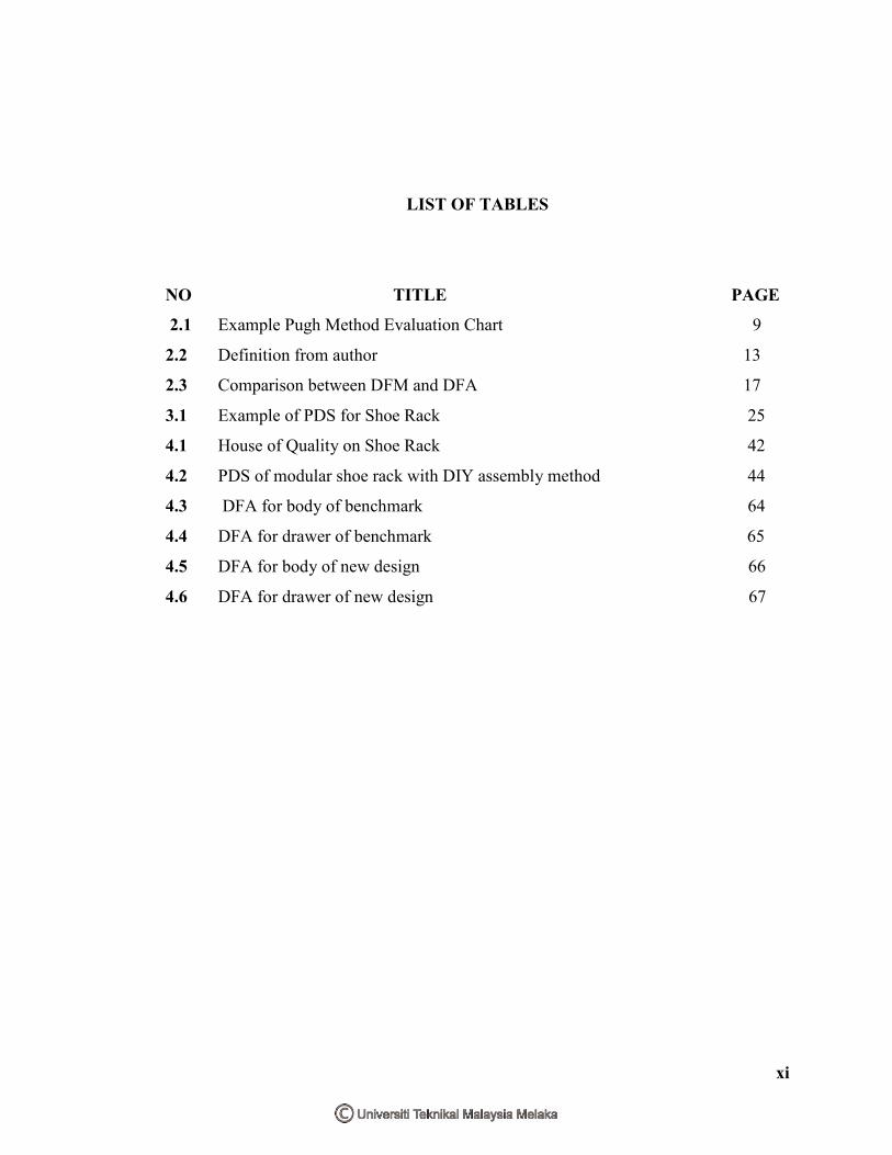
LIST OF TABLES
NO TITLE PAGE
2.1 Example Pugh Method Evaluation Chart 9
2.2 Definition from author 13
2.3 Comparison between DFM and DFA 17
3.1 Example of PDS for Shoe Rack 25
4.1 House of Quality on Shoe Rack 42
4.2 PDS of modular shoe rack with DIY assembly method 44
4.3 DFA for body of benchmark 64
4.4 DFA for drawer of benchmark 65
4.5 DFA for body of new design 66
4.6 DFA for drawer of new design 67
xii
LIST OF FIGURES
NO
TITLE
PAGE
1.1 Example of closed Shoe Rack 1
2.1 Engineering Design Process 6
3.1 Flowchart of the project 20
3.2 Example of House of Quality 22
3.3 CES EDUPACK 2011 Software 26
3.4 Example of overview information from CES EduPack 27
3.5 Product Decomposition of existing design of Shoe Rack 27
3.6 The flow of process brainstorming 29
3.7 Example of Pugh Method selection method 30
3.8 Flow chart of product architecture methodology 31
3.9 Software CATIA V5 34
4.1 Benchmark of Shoe Rack 38
4.2 The shoe rack divided two divisions 39
4.3 The body part of shoe rack 39
4.4 The drawer part of shoe rack 40
4.5 The basic measurement of Benchmark 41
4.6 Product component decomposition of shoe rack 46
4.7 Concept Design 1 46
4.8 Concept Design 2 47
4.9 Concept Design 3 48
4.10 The new concept of shoe rack 50
4.11 Combination two type of shoe rack 50
4.12 Combination four type of shoe rack 51

ii
4.13 The part body of shoe rack 52
4.15 The drawer part of shoe rack 53
4.16 The Philips screw type 53
4.17 Basic properties of MDF 55
4.18 Final concept design for shoe rack (close) 56
4.19 Final concept design for shoe rack (open) 56
4.20 Exploded view for shoe rack 57
4.21 Part 1 (Upper and Lower part) 57
4.22 Part 2 (left and right part) 58
4.23 Part 3 (Lanes board) 58
4.24 Part 5 (Back Cover part) 58
4.25 Part 3 (Drawer) 59
4.26 Part 4 (plywood part) 59
4.27 Part 6 (Connecter part) 59
4.28 Comparison with Benchmark and new concept 60
4.29 Alpha and beta rotational symmetries 61
4.30 Handling Time Table 62
4.31 Insertion time 63
4.32 Prototype product 68
4.33 The drawer part 68
4.34 View inside the body part 69
iii
LIST OF ABBREVIATION
DFMA = Design for Manufacturing and Assembly
DIY = Do It Yourself
PDS = Product Design Specification
HOQ = House of Quality
CATIA = Computer Aided Three-Dimensional Interactive
Application
V5 = Version 5
V6 = Version 6
R20 = Release 20
DFM = Design for manufacturing
DFA = Design for assembly
QFD = Quality Function Deployment
CAD = Computer Aided Design
CAM = Computer Aided Manufacturing
CAE = Computer Aided Engineering
MDF = Medium Density Fiberboard

1
1
CHAPTER 1
INTRODUCTION
1.1 BACKGROUND
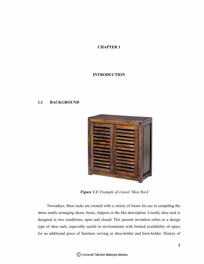
Figure 1.1: Example of closed ‘Shoe Rack’
Nowadays, Shoe racks are created with a variety of forms for use in compiling the
shoes neatly arranging shoes, boots, slippers or the like description. Usually shoe rack is
designed in two conditions, open and closed. This present invention refers to a design
type of shoe rack, especially useful in environments with limited availability of space
for an additional piece of furniture serving as shoe-holder and boot-holder. History of

2
technology the invention of this new design of shoe rack is born to be placed on the
doors of various household environments, or even hung on small wall spaces. The
household problem of putting away shoes is currently solved by various types of
furniture, always requiring a certain space, or with designs to be hung to doors, where
the main elements for putting away footwear.
This shoe rack basic designed form of a box, but every year the design is
constantly changing with more updates design at cheaper price using various materials
and can be more easily used, it also does not focus on one form but has variety of
aesthetic design and easy assembly. Shoe racks are used to look neat and tidy in every
home, office or any place in order to be placed outside and in a place according to their
requirements. Hence, all these problems can be solved by putting the shoes carefully at
the right place, as well as the problem of dust on shoes and the smell can be addressed
using a closed shoe racks.
This project shoe rack is more focused in small design closed shoe rack and
easily lifted. It also can solve some existing problems such as ease to assemble by
yourself. The concept of a closed shoe rack was chosen because the market is many
readily available than the open shoe rack using DIY method. By creating a survey on
this problem, this shoe rack will be designed based on several concepts to provide wider
benefits in the manufacture of this closed shoe rack. In general, this shoe rack will be
more focused on reducing manufacturing costs, easier installation, sturdy, easy
assemble, durable, strong and more attractive

3
1.2 OBJECTIVE
This project is aimed to study the activities involved in design process for
modular product concept for ‘Shoe Rack’ and fabrication of a prototype of the scale 1:2
using sustainable material. The modular product also has to incorporate DIY assembly
method. DFMA of a product development and modular design concept also using in this
project.
1.3 SCOPE
The scope of studies for this project is to focus on the implementation of
modular design concept on close ‘Shoe Rack’ then DFMA method will be apply to the
design for developing process. The final product then will be integrated with ‘DIY’
method. After using these three methods, the detailed design concept selected will be
developed using software CATIA V5R20.
1.4 PROBLEM STATEMENT
Basically, there are a lot of aspects need to be considered when designing the
closed ‘Shoe Rack’. Design of the furniture is essential to ensure that it can easily be
adapted for space layout. One major problem that can be seen in the ready-made design
configuration of advanced shoe rack can’t be changed with the environment.
Furthermore, the existing closed shoe rack product does not use the concept
of DIY, usually this product is preinstalled and caused difficulties to move or slipper the
product for point to another point. The product introduces simple functional design and
easy installation method by incorporation DIY method. The product is aimed be packed
in a flat packed boxes that could fit in box boots of any for ease of transportation.
4
Therefore, to overcome this problem, the modular design shoe rack is proposed
so that this shoe rack can be adapted to the various aspects of the furniture layout.
Through creativity and customer needs, they are able to combine the shoe rack in a
various conditions based on various configuration of the shoe rack. (Snedd, 1992)
5
CHAPTER 2
LITERATURE REVIEW
2.1 INTRODUCTION
This chapter will discuss more about this project using the three concepts. The
first topic to be discussed is modular products in embodiment design section. These
topics also include definition and the advantages of using these concepts. The second
concept will discuss the concept of "Do it yourself’ (DIY) and also the concept of
‘Design for manufacturing and assembly’ (DFMA) for this product design.
Three concepts that will be used in this project is 'modular design', 'Do it yourself’
(DIY) and ‘Design for manufacturing and assembly (DFMA). There are many
advantages through the concept of applied. One of the advantage is modular products to
used for reduced and easier to installed on its own, usually existing indoor shoe racks do
not use the concept of 'DIY', but is ready assembled, just open shelves just a lot of
use the concept of 'DIY'. When a customer installs the product itself, the term 'DIY' will
be used. ‘DIY’ is an act to build or modify without the assistance of any expert and
otherwise do so freely. Usually products with DIY installation methods will be provided
instructions for customers to facilitate the installation and use of basic tools.
6
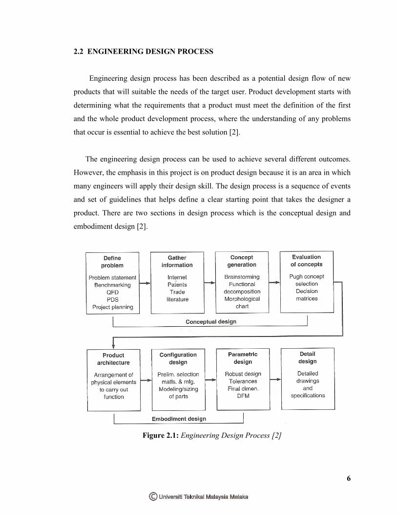
2.2 ENGINEERING DESIGN PROCESS
Engineering design process has been described as a potential design flow of new
products that will suitable the needs of the target user. Product development starts with
determining what the requirements that a product must meet the definition of the first
and the whole product development process, where the understanding of any problems
that occur is essential to achieve the best solution [2].
The engineering design process can be used to achieve several different outcomes.
However, the emphasis in this project is on product design because it is an area in which
many engineers will apply their design skill. The design process is a sequence of events
and set of guidelines that helps define a clear starting point that takes the designer a
product. There are two sections in design process which is the conceptual design and
embodiment design [2].
Figure 2.1: Engineering Design Process [2]

7
2.2.1 Conceptual Design
Conceptual design is the process by which the design is initiated, carried to the
point of creating a number of possible solutions, and narrowed down to a single best
concept. Conceptual design is the phase that requires the greatest creativity, involves the
most uncertainty, and requires coordination among many function in the business
organization. The following are the discrete activities that consider under conceptual
design [1].
Furthermore, to be taken in the early stages of product concept to gather
information related to the literature is the product itself. Relevant information to perform
engineering design is a kind of a lot and come in several forms other than written
words. Some examples are coming from the customer surveys and feedback,
specifications and drawings for the previous version of the product, and so many
resources that are more relevant. By placing the information gathering steps of problem
definition and concept generation step, we can find the information required to
implement the concept of creative solutions.
2.2.1.1 Concept Generation
This concept generation method is a step in the development of the product as an
alternative design concept generated, evaluated, and selected. Terms of design
concepts can be defined as an alternative that includes a minimum of principles, the
embodiment of abstract and geometric [2].
To get the best design concepts, the study should be done in the design
process to generate ideas that are more creative. The first step in implementing the best
ideas are reviewed statement of the problem occurs. An idea that is obtained will be a
concept but the idea is not similar to one another.
8
2.2.1.2 Concept Selection
After several concepts have been identified, the best concept will be used in
this product. Among the methods used in this project to choose the specification
is the Pugh method. This method can choose the product concept based on the criteria
and specifications required in a new product [2]. This method is most effective if all the
engineering design ideas implemented and agreed compared with only one method.
2.2.1.2.1 Pugh Concept Selection Method
The Pugh method can be performed by the following process:
1. Choose the comparison criteria
2. Select the alternative to be compared
3. Generate score
The Pugh selection chart shows that two of the proposed designs rank higher
than the DATUM design. After taking the consideration, the engineering team chooses a
concept to make it as a datum or benchmark. The concept will be given a positive (+)
score if it is better than the datum and vice versa. The concept will be given zero (0)
score if the concept equally with the datum [2]. After all the criterion of the concept and
datum are compared, the three score will be generated based on the previous comparison
score. That three score are the number of positive score, the number of negative score,
the overall total, and the weighted score. The example Pugh method evaluation chart is
shows on Table 2.1.

9
ROW
CRITERIA
CONCEPT
A B C D
1 CRITERIA A + + +
DA
TU
M
2 CRITERIA B = - +
3 CRITERIA C - + -
4 CRITERIA D = = =
5 CRITERIA E + = -
6 CRITERIA F - + +
7 CRITERIA G = = =
8 CRITERIA H + + =
9 CRITERIA I - + -
10 CRITERIA J = = +
PLUSES 3 5 4 0
MINUSES 3 1 3 0
Table 2.1: Example Pugh Method Evaluation Chart [2]