DESIGN PROCESS FOR A MECHANISM - Universidad de los ...
67
DESIGN PROCESS FOR A MECHANISM FOR COFFEE HARVESTING By: Alejandro Cendales Valencia. Mechanical Engineer undergraduate [email protected] [email protected] Thesis Advisor. Giacomo Barbieri Ph.D. Mechanical Engineer [email protected] Universidad de Los Andes Colombia Final Project for Mechanical Engineering Undergraduate August 2017
-
Upload
khangminh22 -
Category
Documents
-
view
1 -
download
0
Transcript of DESIGN PROCESS FOR A MECHANISM - Universidad de los ...
DESIGN PROCESS FOR A MECHANISM
FOR COFFEE HARVESTING
By:
Alejandro Cendales Valencia.
Mechanical Engineer undergraduate
Thesis Advisor.
Giacomo Barbieri Ph.D.
Mechanical Engineer
Universidad de Los Andes Colombia
Final Project for Mechanical Engineering Undergraduate
August 2017
2
Acknowledgment
First and foremost, I must thank my thesis advisor, Ph.D. Giacomo Barbieri. Without his assistance and dedicated
involvement in every step throughout this process, this project would have never been accomplished. I would like
to thank you very much for your support, understanding and guidance over these past 6 months. I would also like to
gratitude you for your work as a teacher, your teaching style and enormous enthusiasm for the topic influenced my
decision towards this project.
I must also thank a colleague of the Department of mechanical engineering, Nicolás Andrés Martinez Franco, for
provide insight with topics that were unknown for me then. Another friend who helped me whenever I needed some
guidance or when I felt lost with academic issues, Juan Sebastián Marín.
Getting through my dissertation required more than academic support, and I have many, many people to thank for
being there whenever I needed them. I cannot express my gratitude and appreciation for their friendship. Juan
Sebastián Woodcock, Miguel Ángel Díaz, Néstor Jauregui, José Luis Briceño, Sergio Andrés Calvo and Marlon
Rodríguez have been outstanding in their personal and professional support during the time I spend at the
University. For many memorable times I must thank you.
Most importantly, none of this could happened without my family. To my parents and my sister, who encouraged
and supported me along this process, thanks for all the time that you’ve spent with me. Every time I was ready to
quit, you did not let me, and I will be forever grateful. This dissertation stands as a testament to your unconditional
love and encouragement.
3
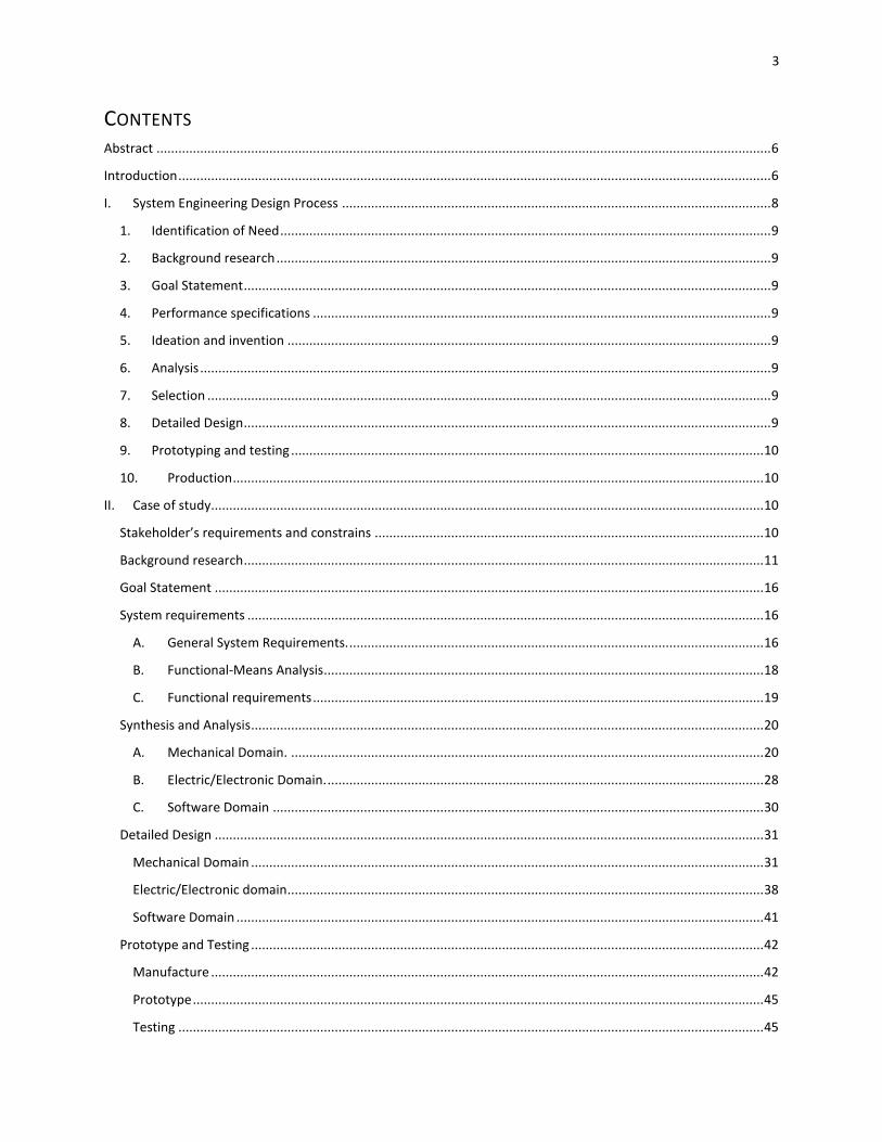
CONTENTS Abstract ......................................................................................................................................................................... 6
Introduction ................................................................................................................................................................... 6
I. System Engineering Design Process ...................................................................................................................... 8
1. Identification of Need ....................................................................................................................................... 9
2. Background research ........................................................................................................................................ 9
3. Goal Statement ................................................................................................................................................. 9
4. Performance specifications .............................................................................................................................. 9
5. Ideation and invention ..................................................................................................................................... 9
6. Analysis ............................................................................................................................................................. 9
7. Selection ........................................................................................................................................................... 9
8. Detailed Design ................................................................................................................................................. 9
9. Prototyping and testing .................................................................................................................................. 10
10. Production .................................................................................................................................................. 10
II. Case of study........................................................................................................................................................ 10
Stakeholder’s requirements and constrains ........................................................................................................... 10
Background research ............................................................................................................................................... 11
Goal Statement ....................................................................................................................................................... 16
System requirements .............................................................................................................................................. 16
A. General System Requirements. .................................................................................................................. 16
B. Functional-Means Analysis ......................................................................................................................... 18
C. Functional requirements ............................................................................................................................ 19
Synthesis and Analysis ............................................................................................................................................. 20
A. Mechanical Domain. .................................................................................................................................. 20
B. Electric/Electronic Domain. ........................................................................................................................ 28
C. Software Domain ....................................................................................................................................... 30
Detailed Design ....................................................................................................................................................... 31
Mechanical Domain ............................................................................................................................................. 31
Electric/Electronic domain................................................................................................................................... 38
Software Domain ................................................................................................................................................. 41
Prototype and Testing ............................................................................................................................................. 42
Manufacture ........................................................................................................................................................ 42
Prototype ............................................................................................................................................................. 45
Testing ................................................................................................................................................................. 45
4
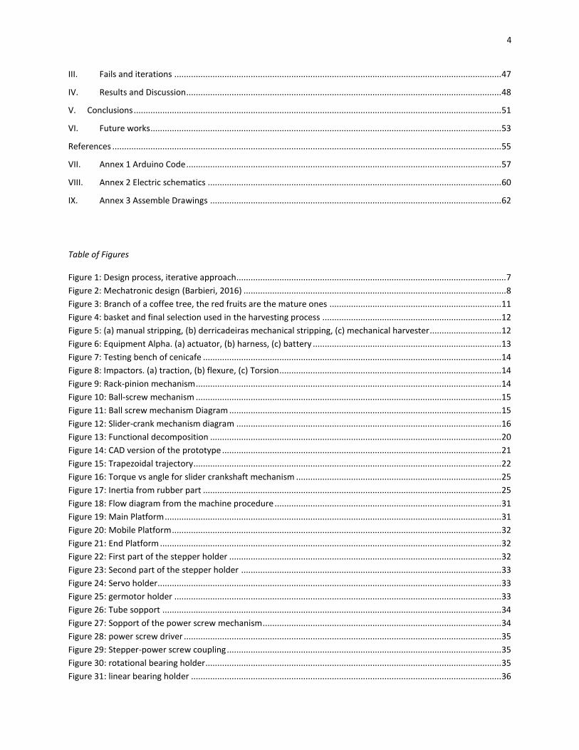
III. Fails and iterations ......................................................................................................................................... 47
IV. Results and Discussion .................................................................................................................................... 48
V. Conclusions .......................................................................................................................................................... 51
VI. Future works ................................................................................................................................................... 53
References ................................................................................................................................................................... 55
VII. Annex 1 Arduino Code .................................................................................................................................... 57
VIII. Annex 2 Electric schematics ........................................................................................................................... 60
IX. Annex 3 Assemble Drawings .......................................................................................................................... 62
Table of Figures
Figure 1: Design process, iterative approach................................................................................................................. 7
Figure 2: Mechatronic design (Barbieri, 2016) .............................................................................................................. 8
Figure 3: Branch of a coffee tree, the red fruits are the mature ones ........................................................................ 11
Figure 4: basket and final selection used in the harvesting process ........................................................................... 12
Figure 5: (a) manual stripping, (b) derricadeiras mechanical stripping, (c) mechanical harvester .............................. 12
Figure 6: Equipment Alpha. (a) actuator, (b) harness, (c) battery ............................................................................... 13
Figure 7: Testing bench of cenicafe ............................................................................................................................. 14
Figure 8: Impactors. (a) traction, (b) flexure, (c) Torsion ............................................................................................. 14
Figure 9: Rack-pinion mechanism ................................................................................................................................ 14
Figure 10: Ball-screw mechanism ................................................................................................................................ 15
Figure 11: Ball screw mechanism Diagram .................................................................................................................. 15
Figure 12: Slider-crank mechanism diagram ............................................................................................................... 16
Figure 13: Functional decomposition .......................................................................................................................... 20
Figure 14: CAD version of the prototype ..................................................................................................................... 21
Figure 15: Trapezoidal trajectory ................................................................................................................................. 22
Figure 16: Torque vs angle for slider crankshaft mechanism ...................................................................................... 25
Figure 17: Inertia from rubber part ............................................................................................................................. 25
Figure 18: Flow diagram from the machine procedure ............................................................................................... 31
Figure 19: Main Platform ............................................................................................................................................. 31
Figure 20: Mobile Platform .......................................................................................................................................... 32
Figure 21: End Platform ............................................................................................................................................... 32
Figure 22: First part of the stepper holder .................................................................................................................. 32
Figure 23: Second part of the stepper holder ............................................................................................................. 33
Figure 24: Servo holder................................................................................................................................................ 33
Figure 25: germotor holder ......................................................................................................................................... 33
Figure 26: Tube sopport .............................................................................................................................................. 34
Figure 27: Sopport of the power screw mechanism .................................................................................................... 34
Figure 28: power screw driver ..................................................................................................................................... 35
Figure 29: Stepper-power screw coupling ................................................................................................................... 35
Figure 30: rotational bearing holder ............................................................................................................................ 35
Figure 31: linear bearing holder .................................................................................................................................. 36
5
Figure 32: Limit switch holder ..................................................................................................................................... 36
Figure 33: rods holders and bering holder levers ........................................................................................................ 37
Figure 34: links of the slider crank mechanism ........................................................................................................... 37
Figure 35: rod of the second actuator ......................................................................................................................... 37
Figure 36: stepper motor dimensions (MotionKing) ................................................................................................... 39
Figure 37: Servo motor dimensions (Servo Database) ................................................................................................ 40
Figure 38: Gearmotor dimensions ............................................................................................................................... 41
Figure 39: Wiring Diagram for the motor shield .......................................................................................................... 41
Figure 40: Drawing of the cuts ..................................................................................................................................... 43
Figure 41: 3D Printers (a) Da Vinci. (B) FORM 1+. (C) MakerBot Replicator. (D) Object Connex (Andes, 2016) ......... 43
Figure 42: Photos of the Prototype ............................................................................................................................. 45
Figure 43: Tracker Test ................................................................................................................................................ 46
Figure 44: Sketch and render of the robotic arm design ............................................................................................. 47
Figure 45: Render of the option with the linear actuators .......................................................................................... 48
Figure 46: Results from the identification of mature coffee fruits thesis ................................................................... 54
Figure 47: Mechanism for the travel amongst the coffee plantation.......................................................................... 55
Tables Index
Table 1: A DESIGN PROCESS (Norton R. L.) .................................................................................................................... 9
Table 2: Report structure Case of study ...................................................................................................................... 10
Table 3: stakeholder requirements ............................................................................................................................. 10
Table 4: Stakeholder Constrains .................................................................................................................................. 11
Table 5: System requirements ..................................................................................................................................... 18
Table 6: Pugh Diagram, First Movement ..................................................................................................................... 19
Table 7: Pugh Diagram, Radial Movement .................................................................................................................. 19
Table 8: Pugh Diagram, Torsion Actuator .................................................................................................................... 19
Table 9: Mechanism of the prototype ......................................................................................................................... 20
Table 10: description of variables for the power screw mechanism ........................................................................... 23
Table 11: Value of the variables for the power screw mechanism ............................................................................. 24
Table 12: Torque and eficiency for power screw mechanism ..................................................................................... 24
Table 13: Properties for structural steel A36 ............................................................................................................... 26
Table 14: Actuators for each mechanism .................................................................................................................... 28
Table 15: Electronics for the prototype ....................................................................................................................... 29
Table 16: Table of electronics with their typology ...................................................................................................... 30
Table 17: Microcontroller specifications ..................................................................................................................... 38
Table 18: Stepper motor specifications ....................................................................................................................... 38
Table 19: Servo motor specifications (Servo Database) .............................................................................................. 39
Table 20: Gearmotor specifications ............................................................................................................................. 40
Table 21: 3D printing settings ...................................................................................................................................... 44
Table 22: Cost of printed parts .................................................................................................................................... 44
Table 23: Values of the test of the first and second actuators .................................................................................... 46
Table 24: Value measured vs code for the third actuator ........................................................................................... 47
Table 25: Validation of the stakeholder's requirements ............................................................................................. 48
Table 26: Validation of the stakeholder's constrains................................................................................................... 49
6
Table 27: Validation of the System requirements ....................................................................................................... 50
ABSTRACT The main objective of this project was to use a design method based on a mechatronic approach in order to develop
a prototype of a Coffee fruit harvester for the Colombian and similar coffee fields. Different areas were analyzed,
such as mechanical, electrical and software domains. A prototype was achieved, but ended with some flaws due to
some manufacturing processes. The purpose of the project was to create a prototype and was NOT to achieve a final
commercial product.
Index Terms: Coffee, Harvester, Harvesting, Machine, Colombia, Colombian Fields, Selected Harvesting, Low Cost,
Arduino, Inventor, Mechanical, Mechatronic, Electronic, Computer Science, Software, Tracker, Design Process,
Design Method, Prototype
INTRODUCTION This document is the thesis project for the implementation of a design process for a mechanism to coffee
harvesting (mechatronic application). The project was made by an iterative designing process, which uses the
integration of 3 fields of engineering that are: mechanical, electronic, and computer science.
The intended purpose of this project is to build the first prototype of the mechanism that can harvest
selected coffee fruits. This prototype should have a system that allow itself to obtain some fruits of a tree without
an interaction with the other ones. The prototype focuses on the part of the mechanism that has the job of collecting
the fruits, which means kinematic and kinetic analysis with the movement parameters. This mechanism could be
part of the solutions for the harvesting problems that occur in Colombia.
7
A formal definition of engineering design can
be found in the curriculum guidelines of the
Accreditation Board for Engineering and Technology
(ABET). The ABET definition states that engineering
design is the process of designing a system, component,
or process to meet desired needs. It is a decision-
making process, in which the basic sciences, like
mathematics, physics and chemistry are applied to
optimally convert resources to meet a stated objective.
Among the fundamentals of the design process is the
establishment of objectives and criteria, synthesis,
analysis, construction, testing, and evaluation. (ABET,
2016)
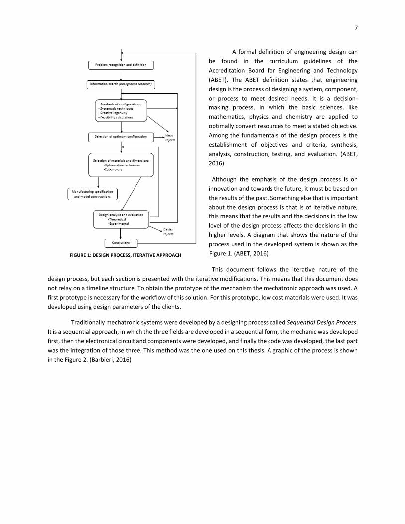
Although the emphasis of the design process is on
innovation and towards the future, it must be based on
the results of the past. Something else that is important
about the design process is that is of iterative nature,
this means that the results and the decisions in the low
level of the design process affects the decisions in the
higher levels. A diagram that shows the nature of the
process used in the developed system is shown as the
Figure 1. (ABET, 2016)
This document follows the iterative nature of the
design process, but each section is presented with the iterative modifications. This means that this document does
not relay on a timeline structure. To obtain the prototype of the mechanism the mechatronic approach was used. A
first prototype is necessary for the workflow of this solution. For this prototype, low cost materials were used. It was
developed using design parameters of the clients.
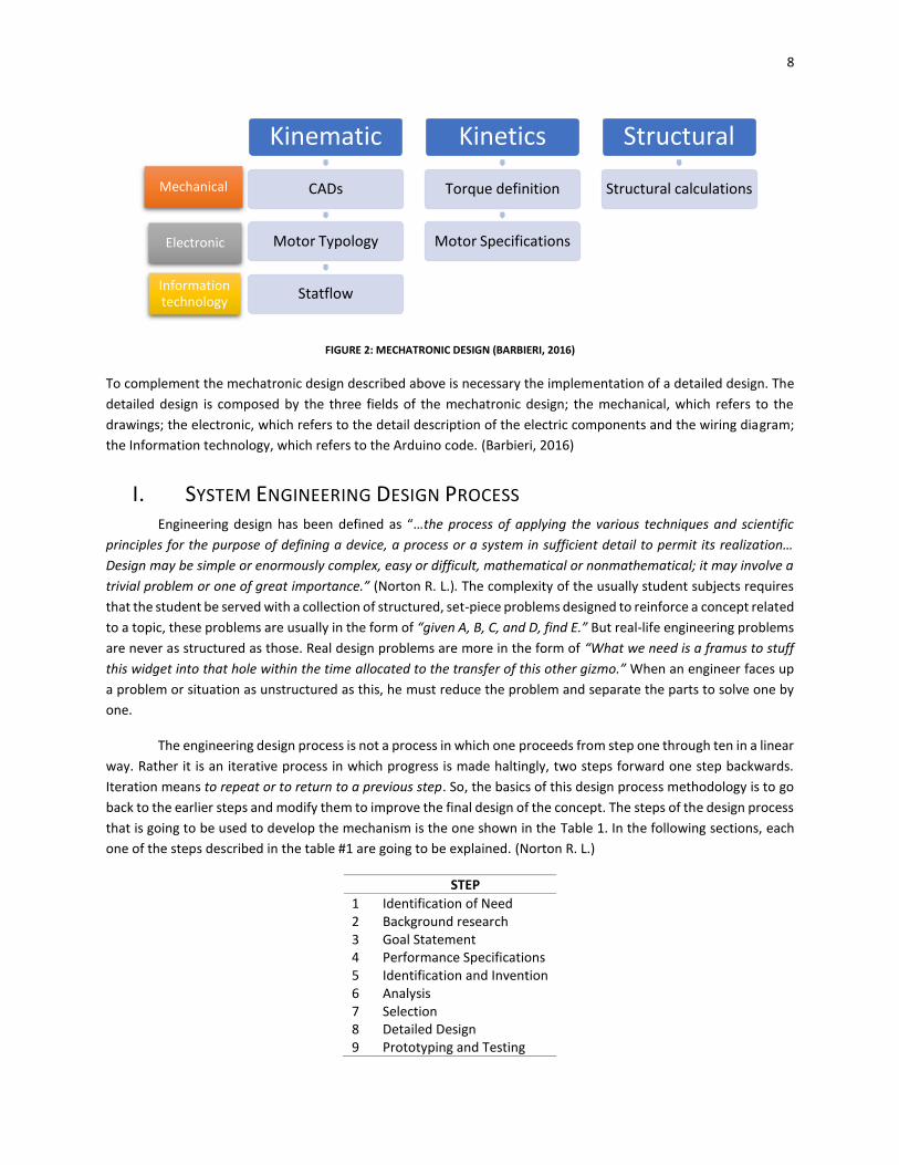
Traditionally mechatronic systems were developed by a designing process called Sequential Design Process.
It is a sequential approach, in which the three fields are developed in a sequential form, the mechanic was developed
first, then the electronical circuit and components were developed, and finally the code was developed, the last part
was the integration of those three. This method was the one used on this thesis. A graphic of the process is shown
in the Figure 2. (Barbieri, 2016)
FIGURE 1: DESIGN PROCESS, ITERATIVE APPROACH
8
FIGURE 2: MECHATRONIC DESIGN (BARBIERI, 2016)
To complement the mechatronic design described above is necessary the implementation of a detailed design. The
detailed design is composed by the three fields of the mechatronic design; the mechanical, which refers to the
drawings; the electronic, which refers to the detail description of the electric components and the wiring diagram;
the Information technology, which refers to the Arduino code. (Barbieri, 2016)
I. SYSTEM ENGINEERING DESIGN PROCESS Engineering design has been defined as “…the process of applying the various techniques and scientific
principles for the purpose of defining a device, a process or a system in sufficient detail to permit its realization…
Design may be simple or enormously complex, easy or difficult, mathematical or nonmathematical; it may involve a
trivial problem or one of great importance.” (Norton R. L.). The complexity of the usually student subjects requires
that the student be served with a collection of structured, set-piece problems designed to reinforce a concept related
to a topic, these problems are usually in the form of “given A, B, C, and D, find E.” But real-life engineering problems
are never as structured as those. Real design problems are more in the form of “What we need is a framus to stuff
this widget into that hole within the time allocated to the transfer of this other gizmo.” When an engineer faces up
a problem or situation as unstructured as this, he must reduce the problem and separate the parts to solve one by
one.
The engineering design process is not a process in which one proceeds from step one through ten in a linear
way. Rather it is an iterative process in which progress is made haltingly, two steps forward one step backwards.
Iteration means to repeat or to return to a previous step. So, the basics of this design process methodology is to go
back to the earlier steps and modify them to improve the final design of the concept. The steps of the design process
that is going to be used to develop the mechanism is the one shown in the Table 1. In the following sections, each
one of the steps described in the table #1 are going to be explained. (Norton R. L.)
STEP
1 Identification of Need 2 Background research 3 Goal Statement 4 Performance Specifications 5 Identification and Invention 6 Analysis 7 Selection 8 Detailed Design 9 Prototyping and Testing
Mechanical
Electronic
Information technology
Kinematic
CADs
Motor Typology
Statflow
Kinetics
Torque definition
Motor Specifications
Structural
Structural calculations
9
10 Production TABLE 1: A DESIGN PROCESS (NORTON R. L.)
1. IDENTIFICATION OF NEED This is the first step of the design process, it is usually done for you by someone, boss or client, saying “What we
need is ….” Usually this statement is short and lacks on detail. It does not give you enough structure to solve the
problem.
2. BACKGROUND RESEARCH This is the most important part of the process, which is usually the one that give you enough information to solve
your problem. Usually this part is misunderstood, it consists on gather information on the relevant physics, chemistry
or other aspects of the problem. Another important reason of doing this background research is to investigate if the
project that is being developed is not already made, in other words to avoid “reinventing the wheel.” On the other
hand, you also may learn and acquire information that could help to the solution of the problem. It is very important
that enough time and energy be expended on this research in order to avoid generating and excellent solution to
the wrong problem or reinventing the wheel. In some reports, this background research is called “state of art”.
3. GOAL STATEMENT Once the background of the original problem has been settle and is perfectly clear, the researcher will be ready to
recast the problem into a more coherent goal statement. This statement should have three characteristics; it should
be concise, be general and be uncolored by any terms.
4. PERFORMANCE SPECIFICATIONS These specifications define what the system must do, this is a set of performance specification or tasks specifications
that indicates how the goal is going to be achieved or accomplished. The purpose of this specifications is to define
the constrains of the problem.
5. IDEATION AND INVENTION This phase is the most difficult of the process. In this phase of the process it is aimed to generate a large number of
ideas without particular regard to quality. This is a common phase to the iteration process, usually after the analysis
step when it is found flaws the researcher come back to this step to improve the ideas for the solution.
6. ANALYSIS For the analysis phase of the design process in order to examine the performance of the design some more
sophisticated analysis techniques are applied. These techniques focus on mathematical models, manufacture and
other processes that made some ideas more reliable than others.
7. SELECTION When the analysis indicates that you have some potentially viable design, the best one must be selected for the next
steps: detailed design, prototyping and testing. This selection process usually involves a comparative analysis of the
solutions that were considered as viable. A decision matrix is usually a great tool for the selection step. This matrix
will give you the answer for the “best” design of the ones that you have found as viable in the “Analysis step”.
8. DETAILED DESIGN
10
This step usually includes the creation of a complete set of assembly and detail drawings or computer-aided design
(CAD) part files, for each and every part used in the design. Each drawing should specify the dimensions and
specifications of materials in order to do that part. From those drawings, a prototype has to be constructed for the
physical testing. In case of discovering more flaws, an iteration is needed in order to repair them.
9. PROTOTYPING AND TESTING One cannot be sure of the viability of any design until it has been built and tested. Any mathematical and physical
model is very useful, but they are never as complete and accurate as the actual one. This involves the construction
and the tests of functionality of the prototype in order to see how it works in the “real world”. In order to see how
a design will work in reality a prototype is built and tested. A scale model could be used in order to save cost of the
prototype.
10. PRODUCTION Finally, in this phase of the design process, after seeing how the prototype works. It is time of manufacture, this
means building the final product or manufacturing thousands or millions of the widget. That is the reason why it is
so important to do a decent job in the design process.
II. CASE OF STUDY For the report of the design process the structure was changed. This was made with the goal to make a best division
of the design process, so the Table 2 show the report structure shown in this document.
SECTION STEP
1.1 Stakeholder’s Requirements 1.2 Background research 1.3 Goal Statement 2.1 System requirements 2.2 Functional means 3 Synthesis and Analysis 4 Detailed Design 5 Prototyping and Testing 6 Discussions 7 Future works
TABLE 2: REPORT STRUCTURE CASE OF STUDY
STAKEHOLDER’S REQUIREMENTS AND CONSTRAINS Requirement Description
Product Physical product (prototype) Functionality Rip an individual fruit in an autonomous way of a coffee tree
-Be able of generate the displacement towards the coffee fruit -Generate enough force to detach the fruit
-Have an impactor generate the detachment Cycle time 13s
TABLE 3: STAKEHOLDER REQUIREMENTS
Constrain Description
Budget 500USD 250USD for components 250USD for manufacture
11
Volume Low Volume prototype Weight Light Model: less than 20 pounds
Scheduling time 16 Weeks TABLE 4: STAKEHOLDER CONSTRAINS
BACKGROUND RESEARCH On the slopes of the three Andes Mountains ranges that cross the country, in an area of approximately
890.000 hectares localized between 1200 to 1800 m above the sea level, there is produced the high-quality coffee
that Colombia exports. This quality is the consequence of the way in which the coffee fruits are harvested. In
Colombia, the harvesters have the knowledge to select the fruits that are mature, because the mature fruits are the
ones that produce the best coffee. In countries like Brazil, the contribution of the engineering along all the steps of
the process have allowed the expansion of the agricultural activity, generating lower production costs than other
countries. For several years, the coffee production process has been wanted to be improved, the engineers have
tried to insert the automatized industry to this field, but they have found some drawbacks. One of the biggest
obstacles are the slopes that distinguished Colombia. Unlike countries as Brazil, Colombia have high slopes in which
Colombians have planted various kinds of crops, some slopes can reach 80%. Because of the topology of Colombian
coffee plantation machines like the ones that are used in other countries cannot be implemented. (Oliveros Tascón
& Sanz-Uribe, 2011)
The method that is used in Colombia is known as selective harvesting. This method is the picking of only
mature coffee fruit by hand. Immature coffee fruits are leaved on the tree for future harvesting. Overripe coffee
(coffee that have been in the tree for a longer time that needed) is usually picked and kept separated from the ones
that are “good”. This process goes over and over till the producer determines that it is no longer worthwhile to
harvest. (Brasil, 2015)
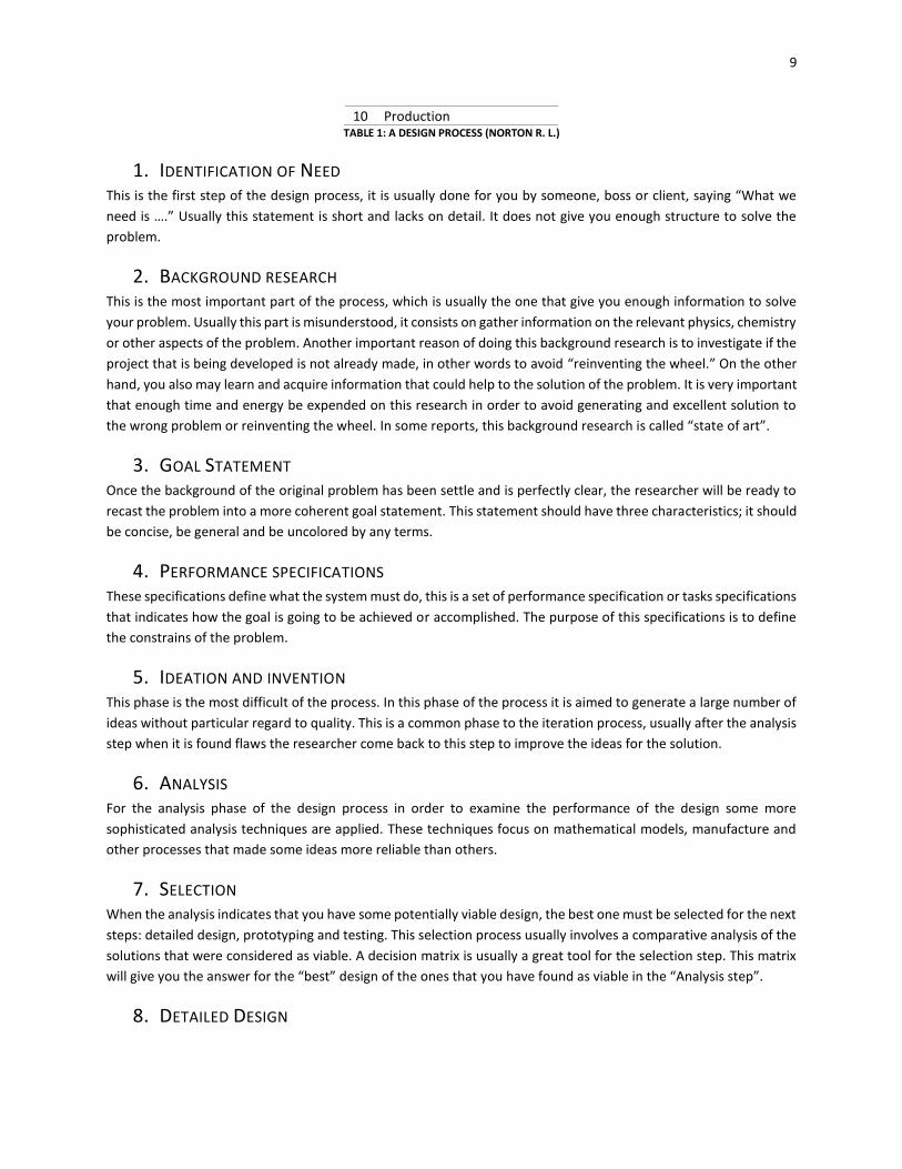
This method is necessary because the quality of the coffee depends on the maturity of the fruits. A branch
of a coffee tree is shown in the Figure 3. As you may see, the fruits have diverse levels of maturity in the same branch,
this property is related to the color of the fruit, the red fruit is the one considered as mature, and so is the one that
the pickers collect.
FIGURE 3: BRANCH OF A COFFEE TREE, THE RED FRUITS ARE THE MATURE ONES
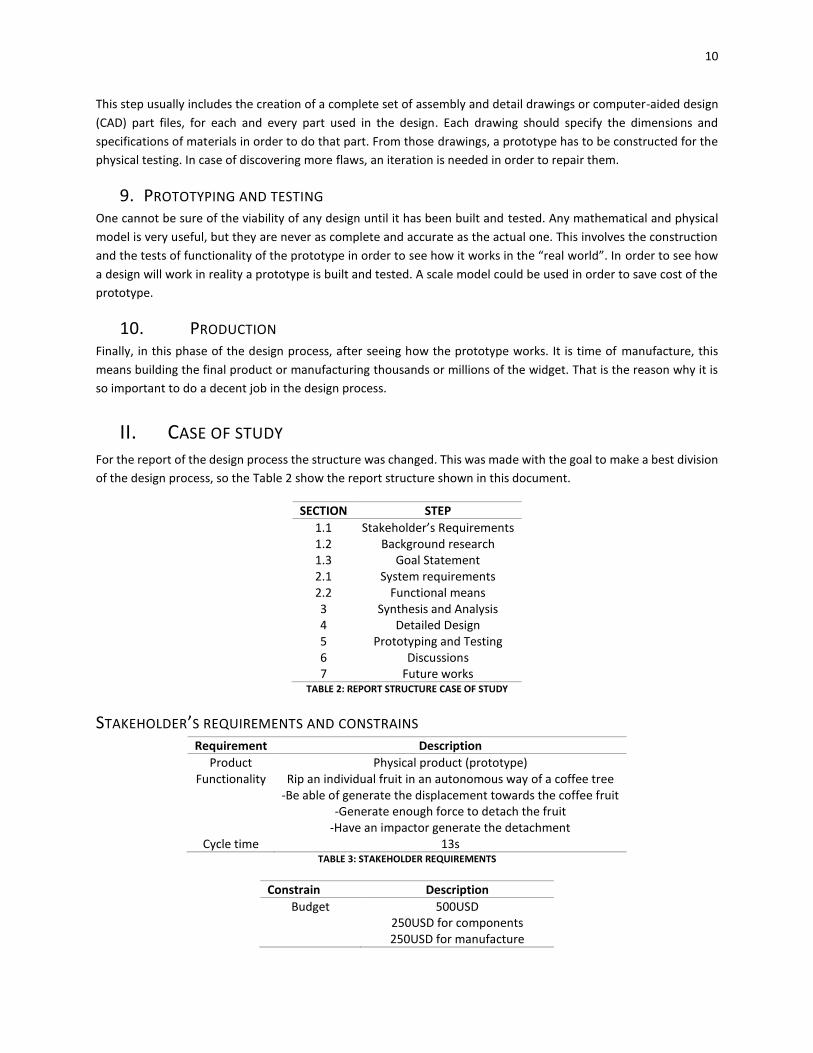
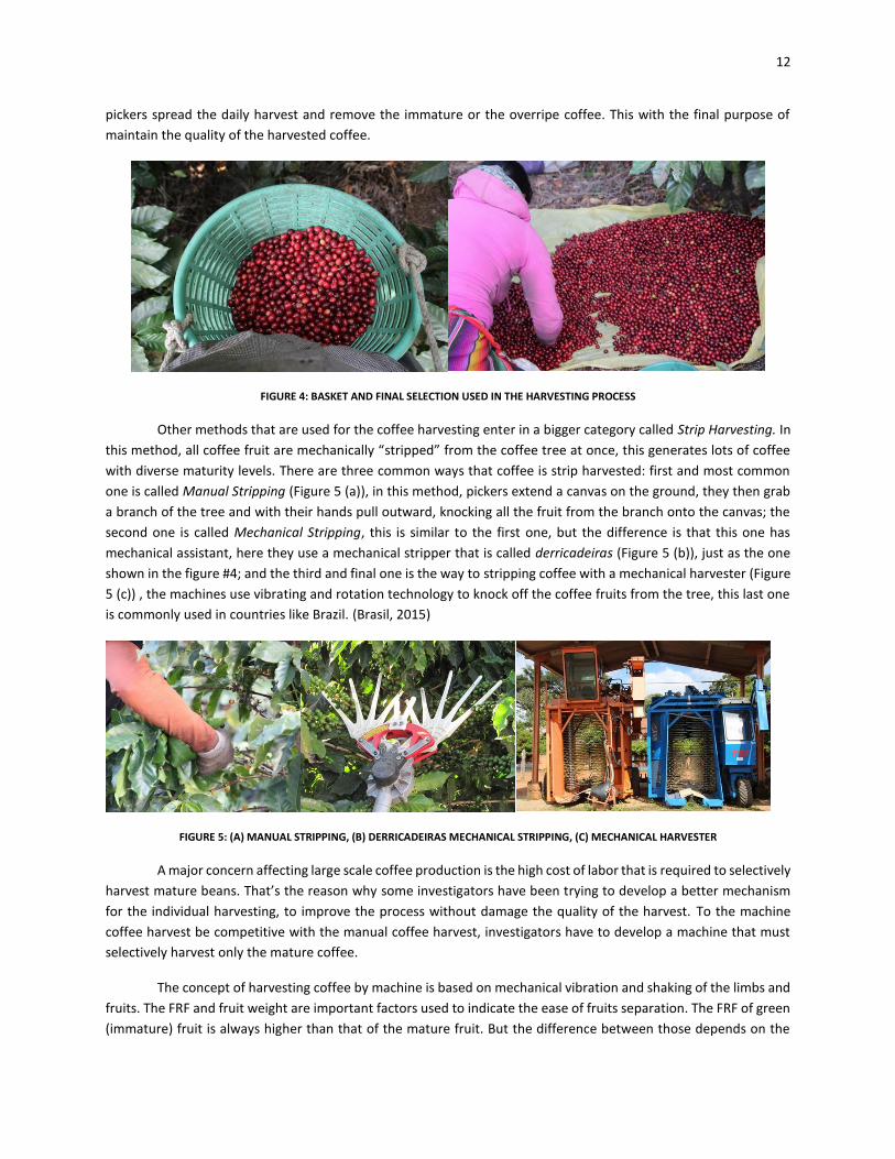
Usually pickers hang a basket from their waist as you may see on the Figure 4, they use this basket to save
the harvest, when the basket is full they empty the basket to another bigger. Later, before the coffee is delivered,
12
pickers spread the daily harvest and remove the immature or the overripe coffee. This with the final purpose of
maintain the quality of the harvested coffee.
FIGURE 4: BASKET AND FINAL SELECTION USED IN THE HARVESTING PROCESS
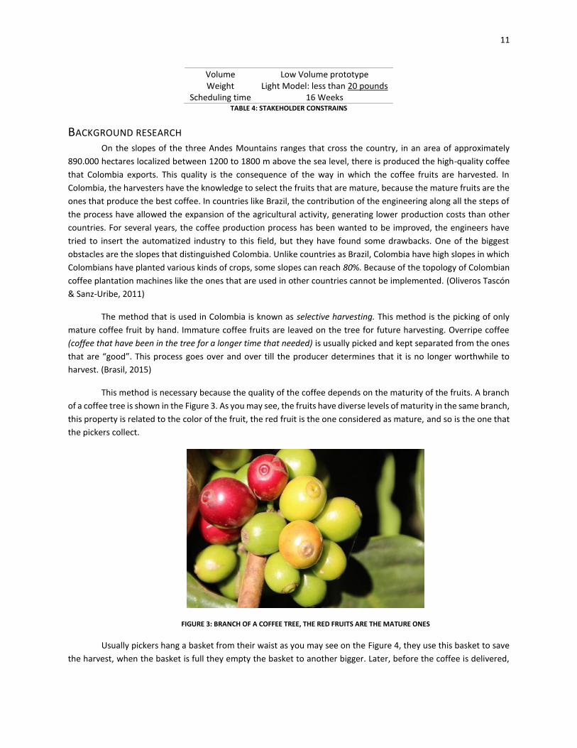
Other methods that are used for the coffee harvesting enter in a bigger category called Strip Harvesting. In
this method, all coffee fruit are mechanically “stripped” from the coffee tree at once, this generates lots of coffee
with diverse maturity levels. There are three common ways that coffee is strip harvested: first and most common
one is called Manual Stripping (Figure 5 (a)), in this method, pickers extend a canvas on the ground, they then grab
a branch of the tree and with their hands pull outward, knocking all the fruit from the branch onto the canvas; the
second one is called Mechanical Stripping, this is similar to the first one, but the difference is that this one has
mechanical assistant, here they use a mechanical stripper that is called derricadeiras (Figure 5 (b)), just as the one
shown in the figure #4; and the third and final one is the way to stripping coffee with a mechanical harvester (Figure
5 (c)) , the machines use vibrating and rotation technology to knock off the coffee fruits from the tree, this last one
is commonly used in countries like Brazil. (Brasil, 2015)
FIGURE 5: (A) MANUAL STRIPPING, (B) DERRICADEIRAS MECHANICAL STRIPPING, (C) MECHANICAL HARVESTER
A major concern affecting large scale coffee production is the high cost of labor that is required to selectively
harvest mature beans. That’s the reason why some investigators have been trying to develop a better mechanism
for the individual harvesting, to improve the process without damage the quality of the harvest. To the machine
coffee harvest be competitive with the manual coffee harvest, investigators have to develop a machine that must
selectively harvest only the mature coffee.
The concept of harvesting coffee by machine is based on mechanical vibration and shaking of the limbs and
fruits. The FRF and fruit weight are important factors used to indicate the ease of fruits separation. The FRF of green
(immature) fruit is always higher than that of the mature fruit. But the difference between those depends on the
13
crop. These machines have vibration fingers that reach through the foliage and branches of the plant. Over 95% of
the crop is removed indiscriminately by these machines. (Brasil, 2015)
Other authors have also developed tools to assist in manual collection and increase the amount of coffee
collected in diverse parts of Colombian coffee fields.
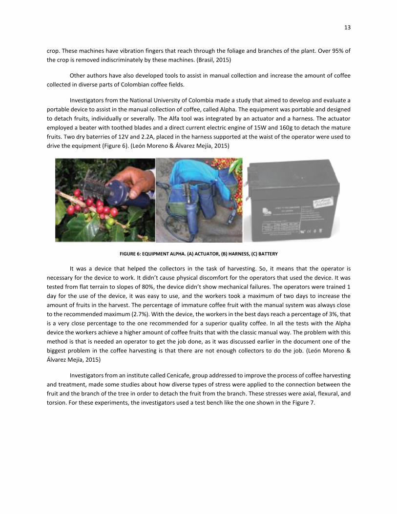
Investigators from the National University of Colombia made a study that aimed to develop and evaluate a
portable device to assist in the manual collection of coffee, called Alpha. The equipment was portable and designed
to detach fruits, individually or severally. The Alfa tool was integrated by an actuator and a harness. The actuator
employed a beater with toothed blades and a direct current electric engine of 15W and 160g to detach the mature
fruits. Two dry baterries of 12V and 2.2A, placed in the harness supported at the waist of the operator were used to
drive the equipment (Figure 6). (León Moreno & Álvarez Mejía, 2015)
FIGURE 6: EQUIPMENT ALPHA. (A) ACTUATOR, (B) HARNESS, (C) BATTERY
It was a device that helped the collectors in the task of harvesting. So, it means that the operator is
necessary for the device to work. It didn’t cause physical discomfort for the operators that used the device. It was
tested from flat terrain to slopes of 80%, the device didn’t show mechanical failures. The operators were trained 1
day for the use of the device, it was easy to use, and the workers took a maximum of two days to increase the
amount of fruits in the harvest. The percentage of immature coffee fruit with the manual system was always close
to the recommended maximum (2.7%). With the device, the workers in the best days reach a percentage of 3%, that
is a very close percentage to the one recommended for a superior quality coffee. In all the tests with the Alpha
device the workers achieve a higher amount of coffee fruits that with the classic manual way. The problem with this
method is that is needed an operator to get the job done, as it was discussed earlier in the document one of the
biggest problem in the coffee harvesting is that there are not enough collectors to do the job. (León Moreno &
Álvarez Mejía, 2015)
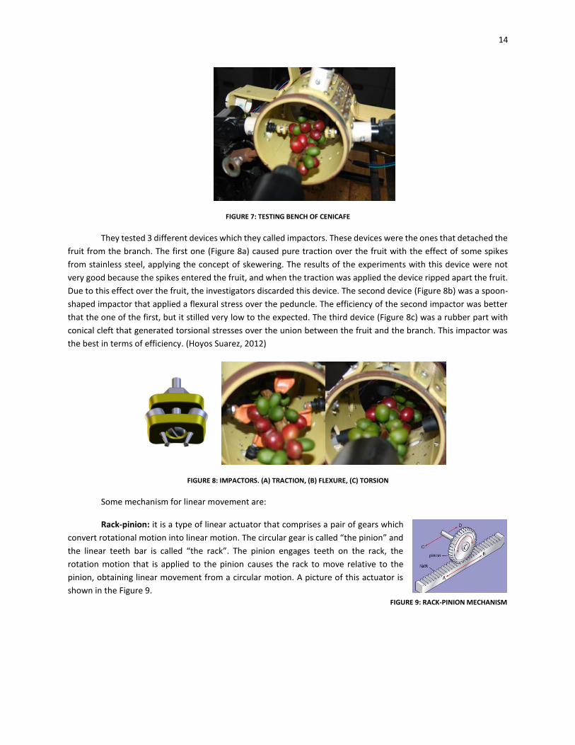
Investigators from an institute called Cenicafe, group addressed to improve the process of coffee harvesting
and treatment, made some studies about how diverse types of stress were applied to the connection between the
fruit and the branch of the tree in order to detach the fruit from the branch. These stresses were axial, flexural, and
torsion. For these experiments, the investigators used a test bench like the one shown in the Figure 7.
14
FIGURE 7: TESTING BENCH OF CENICAFE
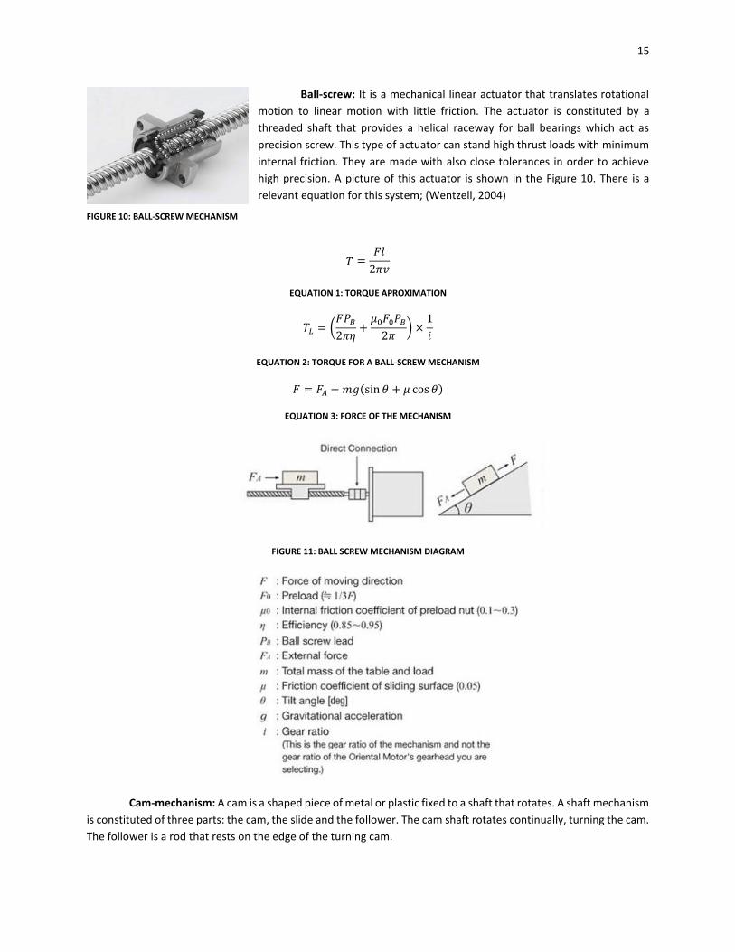
They tested 3 different devices which they called impactors. These devices were the ones that detached the
fruit from the branch. The first one (Figure 8a) caused pure traction over the fruit with the effect of some spikes
from stainless steel, applying the concept of skewering. The results of the experiments with this device were not
very good because the spikes entered the fruit, and when the traction was applied the device ripped apart the fruit.
Due to this effect over the fruit, the investigators discarded this device. The second device (Figure 8b) was a spoon-
shaped impactor that applied a flexural stress over the peduncle. The efficiency of the second impactor was better
that the one of the first, but it stilled very low to the expected. The third device (Figure 8c) was a rubber part with
conical cleft that generated torsional stresses over the union between the fruit and the branch. This impactor was
the best in terms of efficiency. (Hoyos Suarez, 2012)
FIGURE 8: IMPACTORS. (A) TRACTION, (B) FLEXURE, (C) TORSION
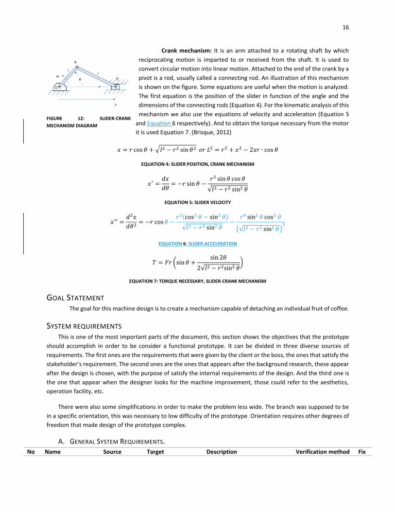
Some mechanism for linear movement are:
Rack-pinion: it is a type of linear actuator that comprises a pair of gears which
convert rotational motion into linear motion. The circular gear is called “the pinion” and
the linear teeth bar is called “the rack”. The pinion engages teeth on the rack, the
rotation motion that is applied to the pinion causes the rack to move relative to the
pinion, obtaining linear movement from a circular motion. A picture of this actuator is
shown in the Figure 9.
FIGURE 9: RACK-PINION MECHANISM
15
Ball-screw: It is a mechanical linear actuator that translates rotational
motion to linear motion with little friction. The actuator is constituted by a
threaded shaft that provides a helical raceway for ball bearings which act as
precision screw. This type of actuator can stand high thrust loads with minimum
internal friction. They are made with also close tolerances in order to achieve
high precision. A picture of this actuator is shown in the Figure 10. There is a
relevant equation for this system; (Wentzell, 2004)
𝑇 =𝐹𝑙
2𝜋𝑣
EQUATION 1: TORQUE APROXIMATION
𝑇𝐿 = (𝐹𝑃𝐵
2𝜋𝜂+
𝜇0𝐹0𝑃𝐵
2𝜋) ×
1
𝑖
EQUATION 2: TORQUE FOR A BALL-SCREW MECHANISM
𝐹 = 𝐹𝐴 + 𝑚𝑔(sin 𝜃 + 𝜇 cos 𝜃)
EQUATION 3: FORCE OF THE MECHANISM
FIGURE 11: BALL SCREW MECHANISM DIAGRAM
Cam-mechanism: A cam is a shaped piece of metal or plastic fixed to a shaft that rotates. A shaft mechanism
is constituted of three parts: the cam, the slide and the follower. The cam shaft rotates continually, turning the cam.
The follower is a rod that rests on the edge of the turning cam.
FIGURE 10: BALL-SCREW MECHANISM
16
Crank mechanism: It is an arm attached to a rotating shaft by which
reciprocating motion is imparted to or received from the shaft. It is used to
convert circular motion into linear motion. Attached to the end of the crank by a
pivot is a rod, usually called a connecting rod. An illustration of this mechanism
is shown on the figure. Some equations are useful when the motion is analyzed.
The first equation is the position of the slider in function of the angle and the
dimensions of the connecting rods (Equation 4). For the kinematic analysis of this
mechanism we also use the equations of velocity and acceleration (Equation 5
and Equation 6 respectively). And to obtain the torque necessary from the motor
it is used Equation 7. (Brisque, 2012)
𝑥 = 𝑟 cos 𝜃 + √𝑙2 − 𝑟2 sin 𝜃2 𝑜𝑟 𝐿2 = 𝑟2 + 𝑥2 − 2𝑥𝑟 ∙ cos 𝜃
EQUATION 4: SLIDER POSITION, CRANK MECHANISM
𝑥′ =𝑑𝑥
𝑑𝜃= −𝑟 sin 𝜃 −
𝑟2 sin 𝜃 cos 𝜃
√𝑙2 − 𝑟2 sin2 𝜃
EQUATION 5: SLIDER VELOCITY
𝑥′′ =𝑑2𝑥
𝑑𝜃2= −𝑟 cos 𝜃 −
𝑟2(cos2 𝜃 − sin2 𝜃)
√𝑙2 − 𝑟2 sin2 𝜃−
𝑟4 sin2 𝜃 cos2 𝜃
(√𝑙2 − 𝑟2 sin2 𝜃)3
EQUATION 6: SLIDER ACCELERATION
𝑇 = 𝐹𝑟 (sin 𝜃 +sin 2𝜃
2√𝑙2 − 𝑟2sin2 𝜃)
EQUATION 7: TORQUE NECESSARY, SLIDER-CRANK MECHANISM
GOAL STATEMENT The goal for this machine design is to create a mechanism capable of detaching an individual fruit of coffee.
SYSTEM REQUIREMENTS This is one of the most important parts of the document, this section shows the objectives that the prototype
should accomplish in order to be consider a functional prototype. It can be divided in three diverse sources of
requirements. The first ones are the requirements that were given by the client or the boss, the ones that satisfy the
stakeholder’s requirement. The second ones are the ones that appears after the background research, these appear
after the design is chosen, with the purpose of satisfy the internal requirements of the design. And the third one is
the one that appear when the designer looks for the machine improvement, those could refer to the aesthetics,
operation facility, etc.
There were also some simplifications in order to make the problem less wide. The branch was supposed to be
in a specific orientation, this was necessary to low difficulty of the prototype. Orientation requires other degrees of
freedom that made design of the prototype complex.
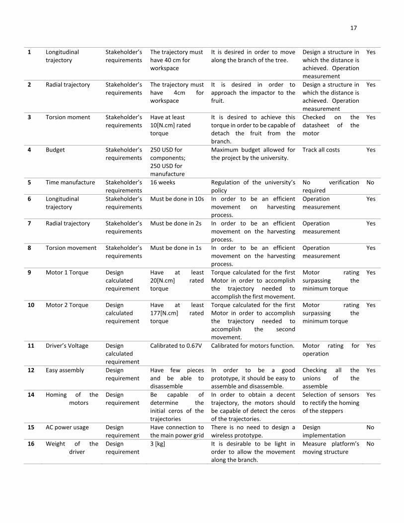
A. GENERAL SYSTEM REQUIREMENTS.
No Name Source Target Description Verification method Fix
FIGURE 12: SLIDER-CRANK
MECHANISM DIAGRAM
17
1 Longitudinal trajectory
Stakeholder’s requirements
The trajectory must have 40 cm for workspace
It is desired in order to move along the branch of the tree.
Design a structure in which the distance is achieved. Operation measurement
Yes
2 Radial trajectory Stakeholder’s requirements
The trajectory must have 4cm for workspace
It is desired in order to approach the impactor to the fruit.
Design a structure in which the distance is achieved. Operation measurement
Yes
3 Torsion moment Stakeholder’s requirements
Have at least 10[N.cm] rated torque
It is desired to achieve this torque in order to be capable of detach the fruit from the branch.
Checked on the datasheet of the motor
Yes
4 Budget Stakeholder’s requirements
250 USD for components; 250 USD for manufacture
Maximum budget allowed for the project by the university.
Track all costs Yes
5 Time manufacture Stakeholder’s requirements
16 weeks Regulation of the university’s policy
No verification required
No
6 Longitudinal trajectory
Stakeholder’s requirements
Must be done in 10s In order to be an efficient movement on harvesting process.
Operation measurement
Yes
7 Radial trajectory Stakeholder’s requirements
Must be done in 2s In order to be an efficient movement on the harvesting process.
Operation measurement
Yes
8 Torsion movement Stakeholder’s requirements
Must be done in 1s In order to be an efficient movement on the harvesting process.
Operation measurement
Yes
9 Motor 1 Torque Design calculated requirement
Have at least 20[N.cm] rated torque
Torque calculated for the first Motor in order to accomplish the trajectory needed to accomplish the first movement.
Motor rating surpassing the minimum torque
Yes
10 Motor 2 Torque Design calculated requirement
Have at least 177[N.cm] rated torque
Torque calculated for the first Motor in order to accomplish the trajectory needed to accomplish the second movement.
Motor rating surpassing the minimum torque
Yes
11 Driver’s Voltage Design calculated requirement
Calibrated to 0.67V Calibrated for motors function. Motor rating for operation
Yes
12 Easy assembly Design requirement
Have few pieces and be able to disassemble
In order to be a good prototype, it should be easy to assemble and disassemble.
Checking all the unions of the assemble
Yes
14 Homing of the motors
Design requirement
Be capable of determine the initial ceros of the trajectories
In order to obtain a decent trajectory, the motors should be capable of detect the ceros of the trajectories.
Selection of sensors to rectify the homing of the steppers
Yes
15 AC power usage Design requirement
Have connection to the main power grid
There is no need to design a wireless prototype.
Design implementation
No
16 Weight of the driver
Design requirement
3 [kg] It is desirable to be light in order to allow the movement along the branch.
Measure platform’s moving structure
No
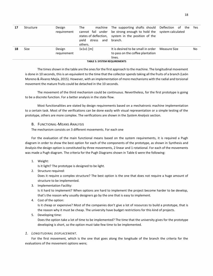
18
17 Structure Design requirement
The machine cannot fail under states of deflection, yield stress and others.
The supporting shafts should be strong enough to hold the system in the position of the branch.
Deflection of the system calculated
Yes
18 Size Design requirement
1x1x1 [m] It is desired to be small in order to pass on the coffee plantation lines.
Measure Size No
TABLE 5: SYSTEM REQUIREMENTS
The times shown in the table are the ones for the first approach to the machine. The longitudinal movement
is done in 10 seconds, this is an equivalent to the time that the collector spends taking all the fruits of a branch (León
Moreno & Álvarez Mejía, 2015). However, with an implementation of more mechanisms with the radial and torsional
movement the mature fruits could be detached in the 10 seconds.
The movement of the third mechanism could be continuous. Nevertheless, for the first prototype is going
to be a discrete function. For a better analysis in the state flow.
Most functionalities are stated by design requirements based on a mechatronic machine implementation
to a certain task. Most of the verifications can be done easily with visual representation or a simple testing of the
prototype, others are more complex. The verifications are shown in the System Analysis section.
B. FUNCTIONAL-MEANS ANALYSIS The mechanism consists on 3 different movements. For each one
For the evaluation of the main functional means based on the system requirements, it is required a Pugh
diagram in order to show the best option for each of the components of the prototype, as shown in Synthesis and
Analysis the design option is constituted by three movements, 2 linear and 1 rotational. For each of the movements
was made a Pugh diagram. The criteria for the Pugh Diagrams shown in Table 6 were the following:
1. Weight:
Is it light? The prototype is designed to be light.
2. Structure required:
Does it require a complex structure? The best option is the one that does not require a huge amount of
structure to be implemented.
3. Implementation Facility:
Is it hard to implement? When options are hard to implement the project become harder to be develop,
that’s the reason why usually designers go by the one that is easy to implement.
4. Cost of the option:
Is it cheap or expensive? Most of the companies don’t give a lot of resources to build a prototype, that is
the reason why it must be cheap. The university have budget restrictions for this kind of projects.
5. Developing time:
Does the option take a lot of time to be implemented? The time that the university gives for the prototype
developing is short, so the option must take few time to be implemented.
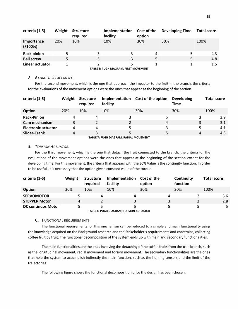
1. LONGITUDINAL DISPLACEMENT.
For the first movement, which is the one that goes along the longitude of the branch the criteria for the
evaluations of the movement options were;
19
criteria (1-5) Weight Structure required
Implementation facility
Cost of the option
Developing Time Total score
Importance (/100%)
20% 10% 10% 30% 30% 100%
Rack pinion 5 3 3 4 5 4.3 Ball screw 5 5 3 5 5 4.8 Linear actuator 1 2 5 1 1 1.5
TABLE 6: PUGH DIAGRAM, FIRST MOVEMENT
2. RADIAL DISPLACEMENT.
For the second movement, which is the one that approach the impactor to the fruit in the branch, the criteria
for the evaluations of the movement options were the ones that appear at the beginning of the section.
criteria (1-5) Weight Structure required
Implementation facility
Cost of the option Developing Time
Total score
Option 20% 10% 10% 30% 30% 100%
Rack-Pinion 4 4 3 5 3 3.9 Cam mechanism 3 2 2 4 3 3.1 Electronic actuator 4 4 5 3 5 4.1 Slider-Crank 4 3 5 5 4 4.3
TABLE 7: PUGH DIAGRAM, RADIAL MOVEMENT
3. TORSION ACTUATOR.
For the third movement, which is the one that detach the fruit connected to the branch, the criteria for the
evaluations of the movement options were the ones that appear at the beginning of the section except for the
developing time. For this movement, the criteria that appears with the 30% Value is the continuity function. In order
to be useful, it is necessary that the option give a constant value of the torque.
criteria (1-5) Weight Structure required
Implementation facility
Cost of the option
Continuity function
Total score
Option 20% 10% 10% 30% 30% 100%
SERVOMOTOR 5 4 4 4 2 3.6 STEPPER Motor 4 2 3 3 2 2.8 DC continuos Motor 5 5 5 5 5 5
TABLE 8: PUGH DIAGRAM, TORSION ACTUATOR
C. FUNCTIONAL REQUIREMENTS
The functional requirements for this mechanism can be reduced to a simple and main functionality using
the knowledge acquired on the Background research and the Stakeholder’s requirements and constrains, collecting
coffee fruit by fruit. The functional decomposition of the system ends up with main and secondary functionalities.
The main functionalities are the ones involving the detaching of the coffee fruits from the tree branch, such
as the longitudinal movement, radial movement and torsion movement. The secondary functionalities are the ones
that help the system to accomplish indirectly the main function, such as the homing sensors and the limit of the
trajectories.
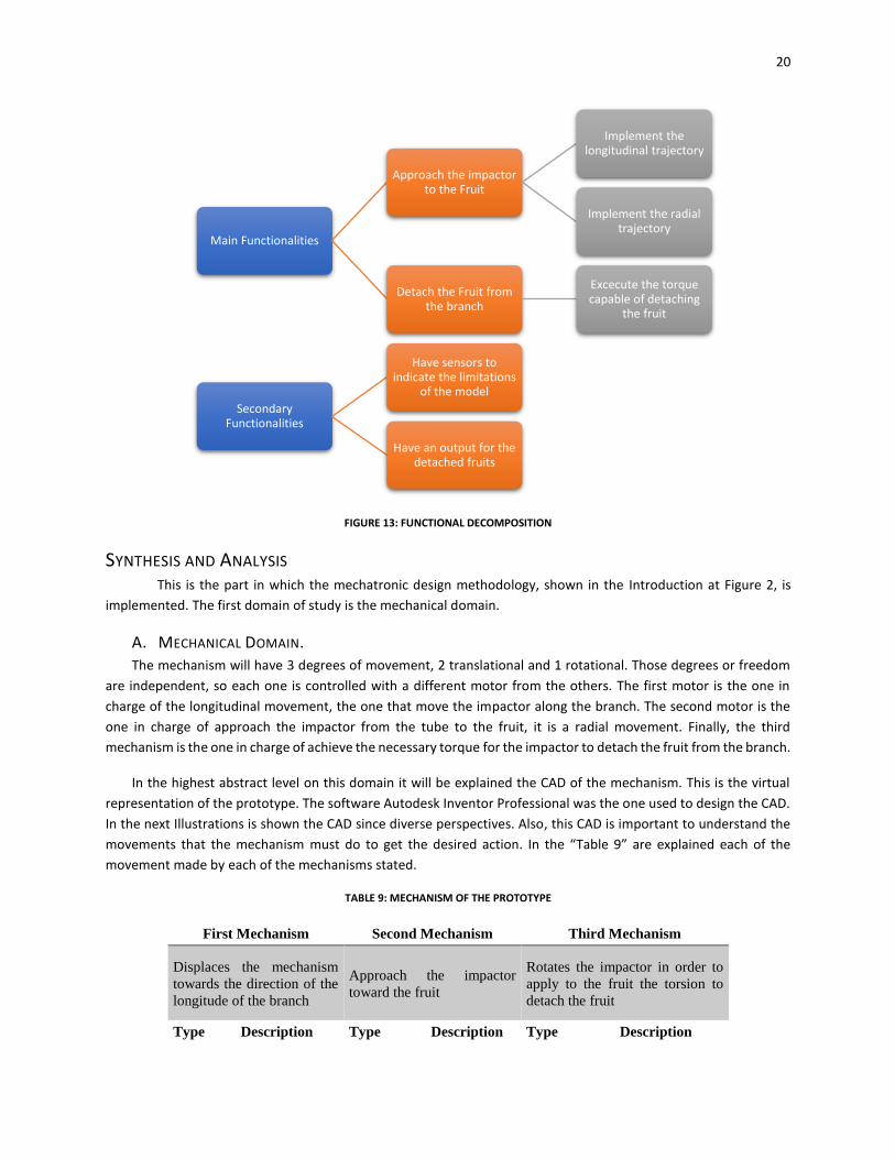
The following figure shows the functional decomposition once the design has been chosen.
20
FIGURE 13: FUNCTIONAL DECOMPOSITION
SYNTHESIS AND ANALYSIS This is the part in which the mechatronic design methodology, shown in the Introduction at Figure 2, is
implemented. The first domain of study is the mechanical domain.
A. MECHANICAL DOMAIN. The mechanism will have 3 degrees of movement, 2 translational and 1 rotational. Those degrees or freedom
are independent, so each one is controlled with a different motor from the others. The first motor is the one in
charge of the longitudinal movement, the one that move the impactor along the branch. The second motor is the
one in charge of approach the impactor from the tube to the fruit, it is a radial movement. Finally, the third
mechanism is the one in charge of achieve the necessary torque for the impactor to detach the fruit from the branch.
In the highest abstract level on this domain it will be explained the CAD of the mechanism. This is the virtual
representation of the prototype. The software Autodesk Inventor Professional was the one used to design the CAD.
In the next Illustrations is shown the CAD since diverse perspectives. Also, this CAD is important to understand the
movements that the mechanism must do to get the desired action. In the “Table 9” are explained each of the
movement made by each of the mechanisms stated.
TABLE 9: MECHANISM OF THE PROTOTYPE
First Mechanism Second Mechanism Third Mechanism
Displaces the mechanism
towards the direction of the
longitude of the branch
Approach the impactor
toward the fruit
Rotates the impactor in order to
apply to the fruit the torsion to
detach the fruit
Type Description Type Description Type Description
Main Functionalities
Approach the impactor to the Fruit
Implement the longitudinal trajectory
Implement the radial trajectory
Detach the Fruit from the branch
Excecute the torque capable of detaching
the fruit
Secondary Functionalities
Have sensors to indicate the limitations
of the model
Have an output for the detached fruits
21
Power
screw
Horizontal
linear
displacement
Slider
Crankshaft
Radial linear
displacement DC Motor
Give torque to the
impactor
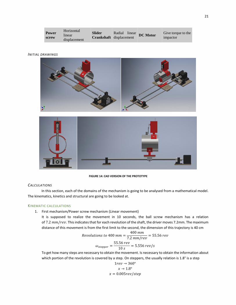
INITIAL DRAWINGS
FIGURE 14: CAD VERSION OF THE PROTOTYPE
CALCULATIONS
In this section, each of the domains of the mechanism is going to be analysed from a mathematical model.
The kinematics, kinetics and structural are going to be looked at.
KINEMATIC CALCULATIONS
1. First mechanism/Power screw mechanism (Linear movement)
It is supposed to realize the movement in 10 seconds, the ball screw mechanism has a relation
of 7.2 𝑚𝑚/𝑟𝑒𝑣. This indicates that for each revolution of the shaft, the driver moves 7.2mm. The maximum
distance of this movement is from the first limit to the second, the dimension of this trajectory is 40 cm
𝑅𝑒𝑣𝑜𝑙𝑢𝑡𝑖𝑜𝑛𝑠 𝑡𝑜 400 𝑚𝑚 =400 𝑚𝑚
7.2 𝑚𝑚/𝑟𝑒𝑣= 55.56 𝑟𝑒𝑣
𝜔𝑠𝑡𝑒𝑝𝑝𝑒𝑟 =55.56 𝑟𝑒𝑣
10 𝑠= 5.556 𝑟𝑒𝑣/𝑠
To get how many steps are necessary to obtain the movement. Is necessary to obtain the information about
which portion of the revolution is covered by a step. On steppers, the usually relation is 1.8° is a step
1𝑟𝑒𝑣 → 360°
𝑥 → 1.8°
𝑥 = 0.005𝑟𝑒𝑣/𝑠𝑡𝑒𝑝

22
𝑆𝑡𝑒𝑝𝑠 =55.56𝑟𝑒𝑣
0.005𝑟𝑒𝑣/𝑠𝑡𝑒𝑝= 11 ∙ 103𝑠𝑡𝑒𝑝𝑠
The motor must make 5.556 revolutions or 11111 full-steps to obtain the movement desired of the
mechanism.
2. Second mechanism/Slider Crankshaft (Linear movement)
The trajectory of the mechanism must be done in 2s. So that’s the time to get the velocity and acceleration of the
mechanism. That means that the 180° revolution must be done in 2s. So
𝜔 =180°
2𝑠=
90°
𝑠∙
𝜋 𝑟𝑎𝑑
180°= 1.5708
𝑟𝑎𝑑
𝑠
The acceleration of the motor is going to be determined with a trapezoidal trajectory, an example of this trajectory
is shown on the Figure 15.
FIGURE 15: TRAPEZOIDAL TRAJECTORY
So, in order to get the values. The distance is divided in 3 sections, the acceleration, the continuous velocity and the
one of the deceleration.
𝑆𝑖 =𝑆𝑡
3=
3,1416𝑟𝑎𝑑
3= 1.0472𝑟𝑎𝑑
And the time is calculated with the same method:
𝑡 =𝑇𝑡
3=
2𝑠
3= 0.666𝑠
The one with the acceleration section:
𝑆 = 𝑆𝑜 + 𝜔𝑜𝑡 +1
2𝛼𝑡2
The values of 𝑆𝑜 and 𝜔𝑜 are zero, so the equation reduces to
𝑆 =1
2𝛼𝑡2 → 𝛼 =
2𝑆
𝑡2
23
𝛼 =2 ∙ 1.0472𝑟𝑎𝑑
(0.666𝑠)2= 4.72184 𝑟𝑎𝑑/𝑠2
𝜔 = 𝛼𝑡 = (4.72184𝑟𝑎𝑑
𝑠2) (0.666𝑠) = 3.1447
𝑟𝑎𝑑
𝑠
For the section of constant velocity, we obtain
𝑆 = 𝜔𝑡 = 3.1447 𝑟𝑎𝑑/𝑠
And the section of deceleration we obtain
𝛼 =2(𝑆 − 𝜔𝑜𝑡)
𝑡2= −4.72184
𝑟𝑎𝑑
𝑠2
For the velocity
𝜔 = −𝛼𝑡 = (−1) (−4.72184𝑟𝑎𝑑
𝑠2) (0.666𝑠) = 3.1447
𝑟𝑎𝑑
𝑠
Then the acceleration of each rod was gotten for the dynamics calculations done in the next section.
For the acceleration of the mechanism is necessary to use the
3. Third mechanism/DC Motor (rotational movement)
This movement must be done in 1s. So, it must do 1 rev in a second in order to break the part that connects
the fruit to the branch.
𝜔 = 1𝑟𝑒𝑣
𝑠= 6.28
𝑟𝑎𝑑
𝑠
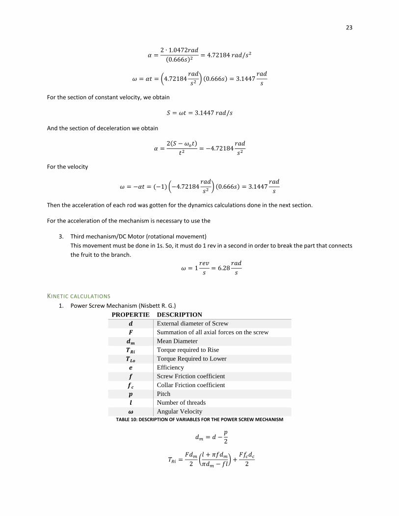
KINETIC CALCULATIONS
1. Power Screw Mechanism (Nisbett R. G.)
PROPERTIE DESCRIPTION
𝒅 External diameter of Screw
𝑭 Summation of all axial forces on the screw
𝒅𝒎 Mean Diameter
𝑻𝑹𝒊 Torque required to Rise
𝑻𝑳𝒐 Torque Required to Lower
𝒆 Efficiency
𝒇 Screw Friction coefficient
𝒇𝒄 Collar Friction coefficient
𝒑 Pitch
𝒍 Number of threads
𝝎 Angular Velocity
TABLE 10: DESCRIPTION OF VARIABLES FOR THE POWER SCREW MECHANISM
𝑑𝑚 = 𝑑 −𝑝
2
𝑇𝑅𝑖 =𝐹𝑑𝑚
2(
𝑙 + 𝜋𝑓𝑑𝑚
𝜋𝑑𝑚 − 𝑓𝑙) +
𝐹𝑓𝑐𝑑𝑐
2
24
𝑇𝐿𝑜 =𝐹𝑑𝑚
2(
𝑙 − 𝜋𝑓𝑑𝑚
𝜋𝑑𝑚 + 𝑓𝑙) +
𝐹𝑓𝑐𝑑𝑐
2
𝑒 =𝐹𝑙
2𝜋𝑇𝑅𝑖
Variable Value Unit Argumentation
𝒑 1.8 mm Screw property given by the manufacture
𝒅 8.1 mm Screw property measured
𝒅𝒓 6.3 mm Screw Property measured
𝒅𝒎 7.2 mm Calculated Value
𝒅𝒄 14.1 mm Collar Property given by the manufacture
𝒇 0.08 [] Typical friction coefficient (Nisbett R. G.)
𝒇𝒄 0.08 [] Typical friction coefficient (Nisbett R. G.)
𝒍 7.2 [] Screw property
𝑭 16.9 N That is the weight of the mobile platform that is going to be moved by the mechanism TABLE 11: VALUE OF THE VARIABLES FOR THE POWER SCREW MECHANISM
Results
𝑻𝑹𝒊 [Nm] 0.0344 𝑻𝑹𝒊 [N.cm] 3.44
𝑻𝑳𝒐 [Nm] 0.0237 𝑻𝑳𝒐 [N.cm] 2.37
𝒆 % 56.3%
TABLE 12: TORQUE AND EFICIENCY FOR POWER SCREW MECHANISM
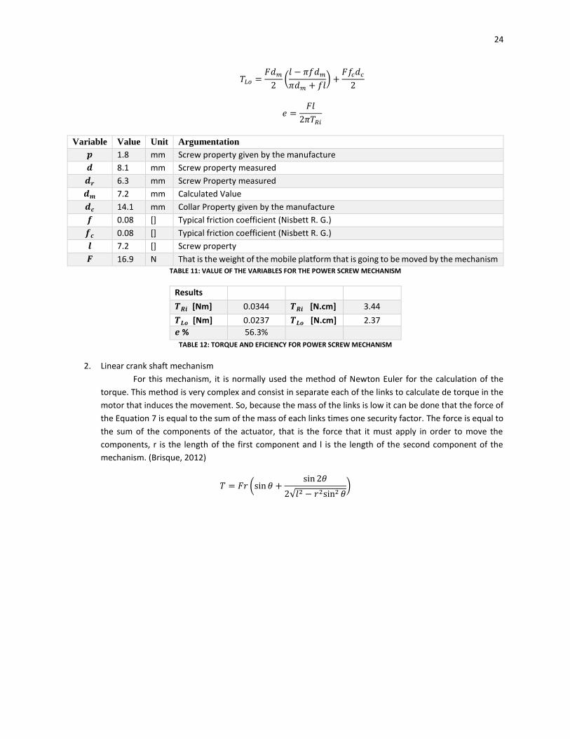
2. Linear crank shaft mechanism
For this mechanism, it is normally used the method of Newton Euler for the calculation of the
torque. This method is very complex and consist in separate each of the links to calculate de torque in the
motor that induces the movement. So, because the mass of the links is low it can be done that the force of
the Equation 7 is equal to the sum of the mass of each links times one security factor. The force is equal to
the sum of the components of the actuator, that is the force that it must apply in order to move the
components, r is the length of the first component and l is the length of the second component of the
mechanism. (Brisque, 2012)
𝑇 = 𝐹𝑟 (sin 𝜃 +sin 2𝜃
2√𝑙2 − 𝑟2sin2 𝜃)
25
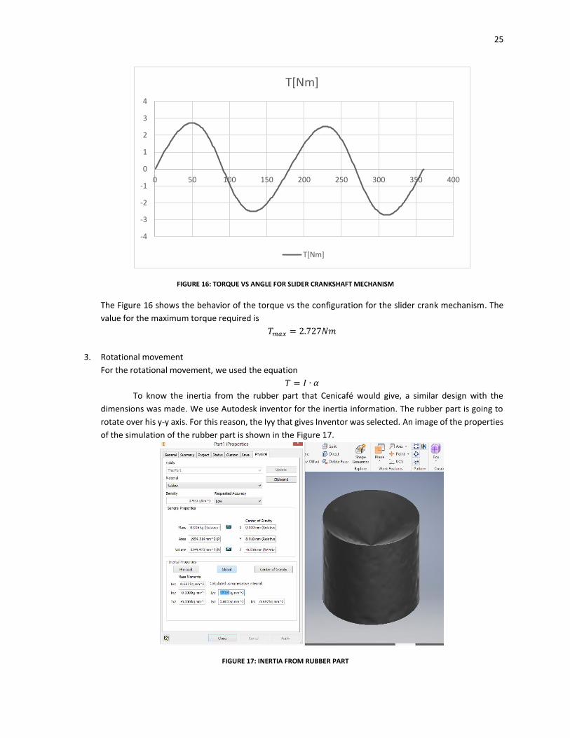
FIGURE 16: TORQUE VS ANGLE FOR SLIDER CRANKSHAFT MECHANISM
The Figure 16 shows the behavior of the torque vs the configuration for the slider crank mechanism. The
value for the maximum torque required is
𝑇𝑚𝑎𝑥 = 2.727𝑁𝑚
3. Rotational movement
For the rotational movement, we used the equation
𝑇 = 𝐼 ∙ 𝛼
To know the inertia from the rubber part that Cenicafé would give, a similar design with the
dimensions was made. We use Autodesk inventor for the inertia information. The rubber part is going to
rotate over his y-y axis. For this reason, the Iyy that gives Inventor was selected. An image of the properties
of the simulation of the rubber part is shown in the Figure 17.
FIGURE 17: INERTIA FROM RUBBER PART
-4
-3
-2
-1
0
1
2
3
4
0 50 100 150 200 250 300 350 400
T[Nm]
T[Nm]
26
𝐼𝑦𝑦 = 0.272 𝑘𝑔𝑚𝑚2 = 0.272 ∗ 10−6𝑘𝑔𝑚2
𝛼 =𝜔
𝑡=
1𝑟𝑒𝑣
𝑠0.25𝑠
= 4𝑟𝑒𝑣
𝑠2= 25.133
𝑟𝑎𝑑
𝑠2
𝑇 = 0.272 ∗ 10−6𝑘𝑔 𝑚2 ∗ 25.133𝑟𝑎𝑑
𝑠2= 6.84 ∗ 10−6𝑁𝑚
𝑇 = 6.84 ∗ 10−4𝑁𝑐𝑚
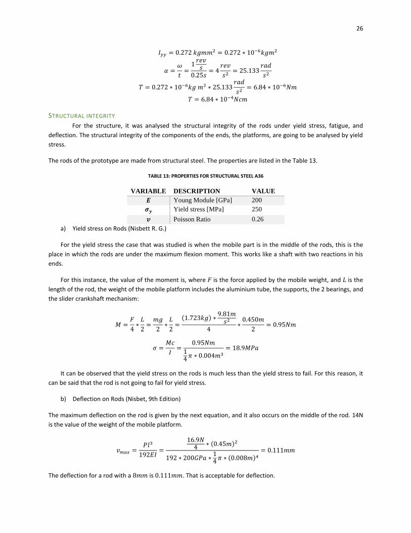
STRUCTURAL INTEGRITY
For the structure, it was analysed the structural integrity of the rods under yield stress, fatigue, and
deflection. The structural integrity of the components of the ends, the platforms, are going to be analysed by yield
stress.
The rods of the prototype are made from structural steel. The properties are listed in the Table 13.
TABLE 13: PROPERTIES FOR STRUCTURAL STEEL A36
VARIABLE DESCRIPTION VALUE
𝑬 Young Module [GPa] 200
𝝈𝒚 Yield stress [MPa] 250
𝒗 Poisson Ratio 0.26
a) Yield stress on Rods (Nisbett R. G.)
For the yield stress the case that was studied is when the mobile part is in the middle of the rods, this is the
place in which the rods are under the maximum flexion moment. This works like a shaft with two reactions in his
ends.
For this instance, the value of the moment is, where 𝐹 is the force applied by the mobile weight, and 𝐿 is the
length of the rod, the weight of the mobile platform includes the aluminium tube, the supports, the 2 bearings, and
the slider crankshaft mechanism:
𝑀 =𝐹
4∗
𝐿
2=
𝑚𝑔
2∗
𝐿
2=
(1.723𝑘𝑔) ∗9.81𝑚
𝑠2
4∗
0.450𝑚
2= 0.95𝑁𝑚
𝜎 =𝑀𝑐
𝐼=
0.95𝑁𝑚
14
𝜋 ∗ 0.004𝑚3= 18.9𝑀𝑃𝑎
It can be observed that the yield stress on the rods is much less than the yield stress to fail. For this reason, it
can be said that the rod is not going to fail for yield stress.
b) Deflection on Rods (Nisbet, 9th Edition)
The maximum deflection on the rod is given by the next equation, and it also occurs on the middle of the rod. 14N
is the value of the weight of the mobile platform.
𝑣𝑚𝑎𝑥 =𝑃𝑙3
192𝐸𝐼=
16.9𝑁4
∗ (0.45𝑚)2
192 ∗ 200𝐺𝑃𝑎 ∗14
𝜋 ∗ (0.008𝑚)4= 0.111𝑚𝑚
The deflection for a rod with a 8𝑚𝑚 is 0.111𝑚𝑚. That is acceptable for deflection.
27
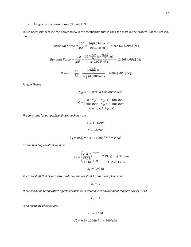
c) Fatigue on the power screw (Nisbett R. G.)
This is necessary because the power screw is the mechanism that is used the most in the process. For this reason,
the
𝑇𝑜𝑟𝑠𝑖𝑜𝑛𝑎𝑙 𝐹𝑜𝑟𝑐𝑒 =16𝑇
𝜋𝑑3=
16(0.0344 𝑁𝑚)
𝜋(0.0083𝑚3)= 0.3422 [𝑀𝑃𝑎] (𝑀)
𝐵𝑒𝑛𝑑𝑖𝑛𝑔 𝐹𝑜𝑟𝑐𝑒 =32𝑀
𝜋𝑑3=
32(16.9
6 𝑁 ∗
0.452
𝑚)
𝜋(0.0083𝑚3)= 12.608 [𝑀𝑃𝑎] (𝐴)
𝑆ℎ𝑒𝑎𝑟 𝜏 =4𝑉
3𝐴=
4(16.9
3 𝑁)
3(𝜋4
(0.0082𝑚2))= 0.084 [𝑀𝑃𝑎] (𝐴)
Fatigue Theory
𝑆𝑢𝑡 = 1000 𝑀𝑃𝑎 𝑓𝑜𝑟 𝑆𝑖𝑙𝑣𝑒𝑟 𝑆𝑡𝑒𝑒𝑙
𝑆𝑒′ = {
0.5 𝑆𝑢𝑡 𝑆𝑢𝑡 ≤ 1 400 𝑀𝑃𝑎700 𝑀𝑃𝑎 𝑆𝑢𝑡 > 1 400 𝑀𝑃𝑎
𝑆𝑒 = 𝑘𝑎𝑘𝑏𝑘𝑐𝑘𝑑𝑘𝑒𝑆𝑒′
The constants for a superficial finish machined are
𝑎 = 4.51𝑀𝑃𝑎
𝑏 = −0.265
𝑘𝑎 = 𝑎𝑆𝑢𝑡𝑏 = 4.51 ∗ 1000−0.265 = 0.723
For the bending constant we have
𝑘𝑏 = {
(𝑑
7.62)
−0.107
2.79 ≤ 𝑑 ≤ 51 𝑚𝑚
1.51𝑑−0.157 51 < 254 𝑚𝑚
𝑘𝑏 = 0.9948
Since is a shaft that is in constant rotation the constant 𝑘𝑐 has a complete value
𝑘𝑐 = 1
There will be no temperature effects because all is worked with environment temperature (9-30°C)
𝑘𝑑 = 1
For a reliability of 99.9999%
𝑘𝑒 = 0.620
𝑆𝑒′ = 0.5 ∗ 1000𝑀𝑃𝑎 = 500𝑀𝑃𝑎
28
𝑆𝑒 = 223𝑀𝑃𝑎
To determine the fatigue stress concentration factor 𝐾𝑓 and 𝐾𝑓𝑠
𝐾𝑓 = 1 + 𝑞(𝐾𝑡 − 1)
𝐾𝑓𝑠 = 1 + 𝑞𝑠(𝐾𝑡𝑠 − 1)
𝑞 = 𝑞𝑠 = 0.8
𝐾𝑡𝑠 = 2.5 𝑓𝑜𝑟 𝑝𝑜𝑤𝑒𝑟 𝑠𝑐𝑟𝑒𝑤 𝑠ℎ𝑎𝑓𝑡𝑠
𝐾𝑡 = 1.94 𝑓𝑜𝑟 𝑝𝑜𝑤𝑒𝑟 𝑠𝑐𝑟𝑒𝑤 𝑠ℎ𝑎𝑓𝑡𝑠
𝐾𝑓𝑠 = 2.2
𝐾𝑓 = 1.752
Using the criteria given by DE-Goodman for a conservative design,
1
𝑛=
16
𝜋𝑑3{
1
𝑆𝑒
[4(𝐾𝑓𝑀𝑎)2
+ 3(𝐾𝑓𝑠𝑇𝑎)2
]
12
+1
𝑆𝑢𝑡
[4(𝐾𝑓𝑀𝑚)2
+ 3(𝐾𝑓𝑠𝑇𝑚)2
]
12
}
1
𝑛= 0.1994
𝑛 = 5.0147
The evaluation of the diameter of the power screw shaft is good for the DE-Goodman criteria, as it can be seen the
security factor is greater than 1.
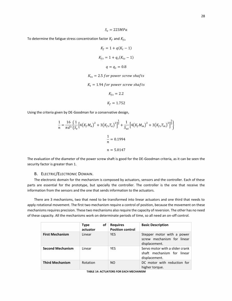
B. ELECTRIC/ELECTRONIC DOMAIN. The electronic domain for the mechanism is composed by actuators, sensors and the controller. Each of these
parts are essential for the prototype, but specially the controller. The controller is the one that receive the
information from the sensors and the one that sends information to the actuators.
There are 3 mechanisms, two that need to be transformed into linear actuators and one third that needs to
apply rotational movement. The first two mechanism require a control of position, because the movement on these
mechanisms requires precision. These two mechanisms also require the capacity of reversion. The other has no need
of these capacity. All the mechanisms work on determinate periods of time, so all need an on-off control.
Type of actuator
Requires Position control
Basic Description
First Mechanism Linear YES Stepper motor with a power screw mechanism for linear displacement.
Second Mechanism Linear YES Servo motor with a slider crank shaft mechanism for linear displacement.
Third Mechanism Rotation NO DC motor with reduction for higher torque.
TABLE 14: ACTUATORS FOR EACH MECHANISM
29
Stepper motors and servo motors can provide a controlled position. The difference between the two is that
the stepper motor is useful in case continuous rotations are wanted, on the other hand servos are useful in case a
movement between 0 and 180 degrees is wanted. Both have tolerances, however the tolerances on the stepper
motors are better. Because of the ability of continuous rotation and closed position tolerances a stepper motor was
chosen for the first mechanism. Because of its ease to use and the necessity for positioning in some angles for the
slider crank mechanism the servo motor was chosen for the second mechanism.
Stepper motors can provide control over position but cannot provide information on initial states. For this
reason, limit switches are required to initialize the position for the stepper. For instance, a limit switch in needed for
the “housing” of the motor. On the other hand, the servo can provide information on initial states, so the limit
switches are only required for the stepper solution.
For the third mechanism the position control is not necessary, the information on initial states is not
required neither. The movement that is required for this mechanism is continuous rotation. Therefore, a DC motor
can be used for this mechanism. However, the common DC don’t give enough torque to detach the coffee fruit from
the branch. To obtain this torque a reduction box can be attached to the motor. Another option is to get a gearmotor
that gives the required torque.
Finally, a controller with the capacity to control all the different motor types and the sensors is needed. A
controller that can work with a servo, a stepper and a gearmotor is needed.
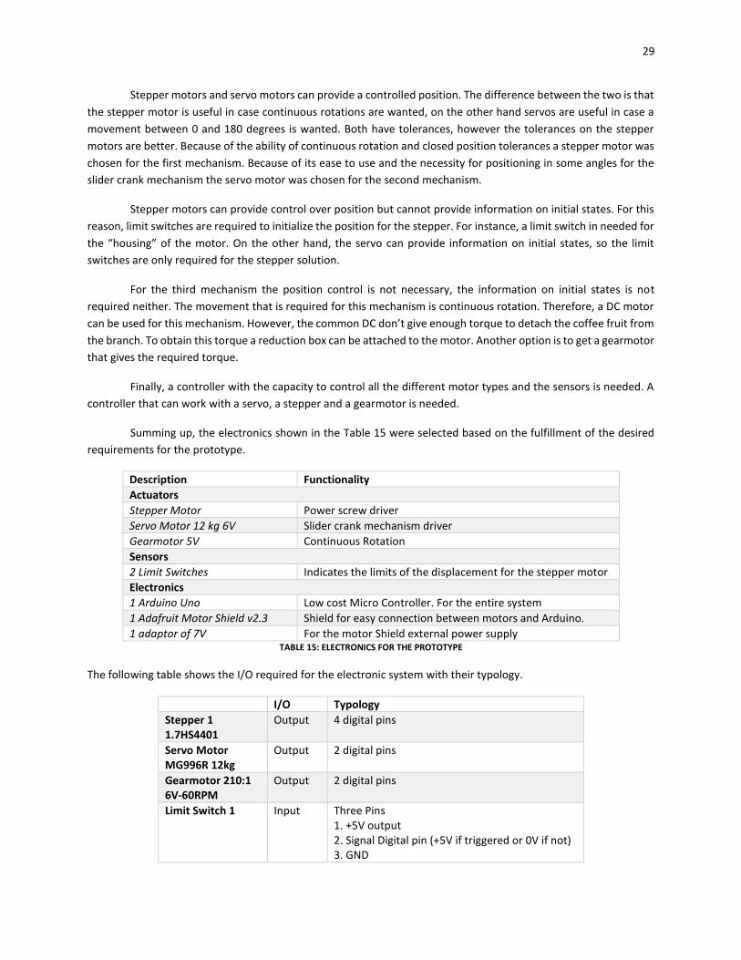
Summing up, the electronics shown in the Table 15 were selected based on the fulfillment of the desired
requirements for the prototype.
Description Functionality
Actuators
Stepper Motor Power screw driver
Servo Motor 12 kg 6V Slider crank mechanism driver
Gearmotor 5V Continuous Rotation
Sensors
2 Limit Switches Indicates the limits of the displacement for the stepper motor
Electronics
1 Arduino Uno Low cost Micro Controller. For the entire system
1 Adafruit Motor Shield v2.3 Shield for easy connection between motors and Arduino.
1 adaptor of 7V For the motor Shield external power supply TABLE 15: ELECTRONICS FOR THE PROTOTYPE
The following table shows the I/O required for the electronic system with their typology.
I/O Typology
Stepper 1 1.7HS4401
Output 4 digital pins
Servo Motor MG996R 12kg
Output 2 digital pins
Gearmotor 210:1 6V-60RPM
Output 2 digital pins
Limit Switch 1 Input Three Pins 1. +5V output 2. Signal Digital pin (+5V if triggered or 0V if not) 3. GND

30
Limit Switch 2 Input Three Pins 1. +5V output 2. Signal Digital pin (+5V if triggered or 0V if not) 3. GND
TABLE 16: TABLE OF ELECTRONICS WITH THEIR TYPOLOGY
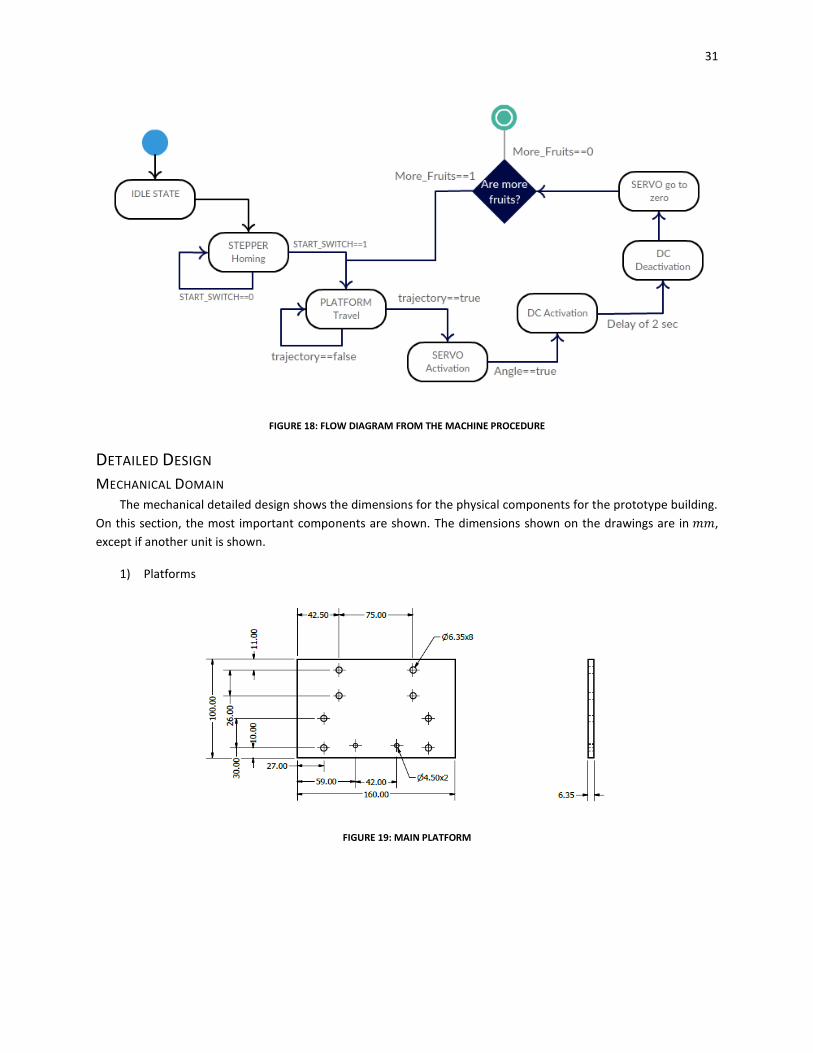
C. SOFTWARE DOMAIN a) Flow Diagram
When the machine is turned on, there is nothing that the user must do physically. The only thing that the user
must do is to give the information to the program, the coordinates where the fruit is placed. A depth and a length
are needed, this information in the future is going to be given by a complementary part of the machine, the one that
identifies where are the fruits in space.
The process that is performed by the machine is divided in 5 sections,
1. Homing
Homing is to ensure machine is in its initial position before the other procedures. It is required;
a. The slider crank mechanism needs to be in its initial position.
b. The mobile platform is in its initial position.
c. The gearmotor and the servo need to be off, they don’t make any action on this step.
2. Traveling
Traveling is the step in which the platform travels in the length of the branch to the desired position.
a. Transport the platform to the desired position
b. The stepper is active on this section.
3. Approach to the fruit
This step is to bring closer the rubber actuator to the fruit
a. The servo starts running and goes to the angle equivalent to the depth selected by the user.
b. The stepper is needed to be still.
4. Detachment
In this step the fruit is detached from the branch
a. The servo and the stepper are needed to be still.
b. The gearmotor starts working for 2 seconds to make the fruit detach from the branch
5. Final
This step is to finalize the procedure
a. The gearmotor is turned off
b. The slider crank mechanism goes to its initial position
31
FIGURE 18: FLOW DIAGRAM FROM THE MACHINE PROCEDURE
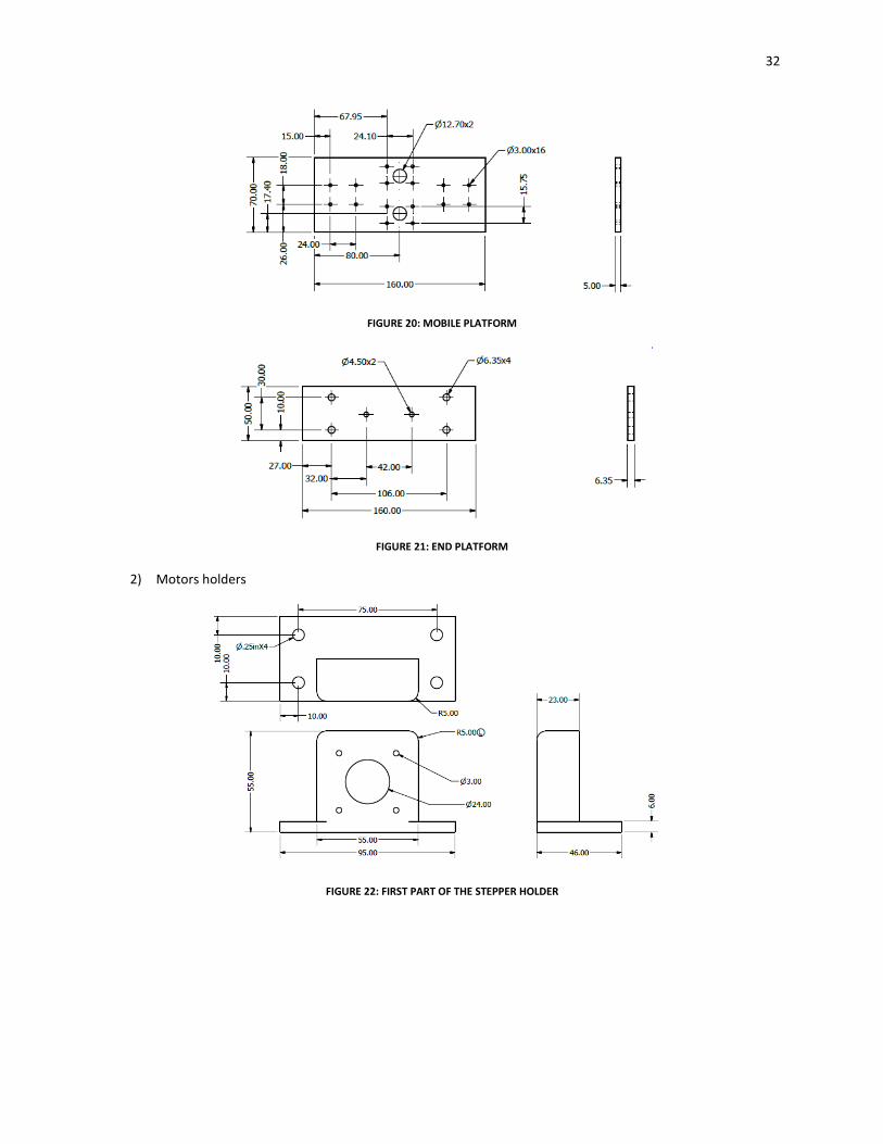
DETAILED DESIGN
MECHANICAL DOMAIN The mechanical detailed design shows the dimensions for the physical components for the prototype building.
On this section, the most important components are shown. The dimensions shown on the drawings are in 𝑚𝑚,
except if another unit is shown.
1) Platforms
FIGURE 19: MAIN PLATFORM
32
FIGURE 20: MOBILE PLATFORM
FIGURE 21: END PLATFORM
2) Motors holders
FIGURE 22: FIRST PART OF THE STEPPER HOLDER
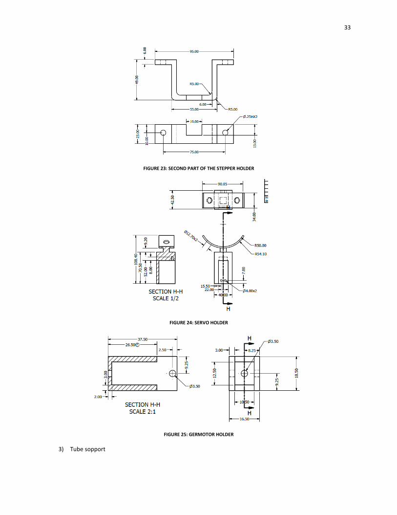
33
FIGURE 23: SECOND PART OF THE STEPPER HOLDER
FIGURE 24: SERVO HOLDER
FIGURE 25: GERMOTOR HOLDER
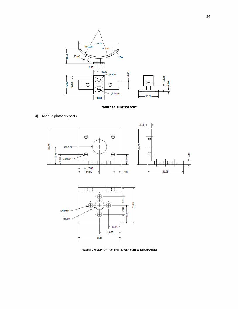
3) Tube sopport
34
FIGURE 26: TUBE SOPPORT
4) Mobile platform parts
FIGURE 27: SOPPORT OF THE POWER SCREW MECHANISM
35
FIGURE 28: POWER SCREW DRIVER
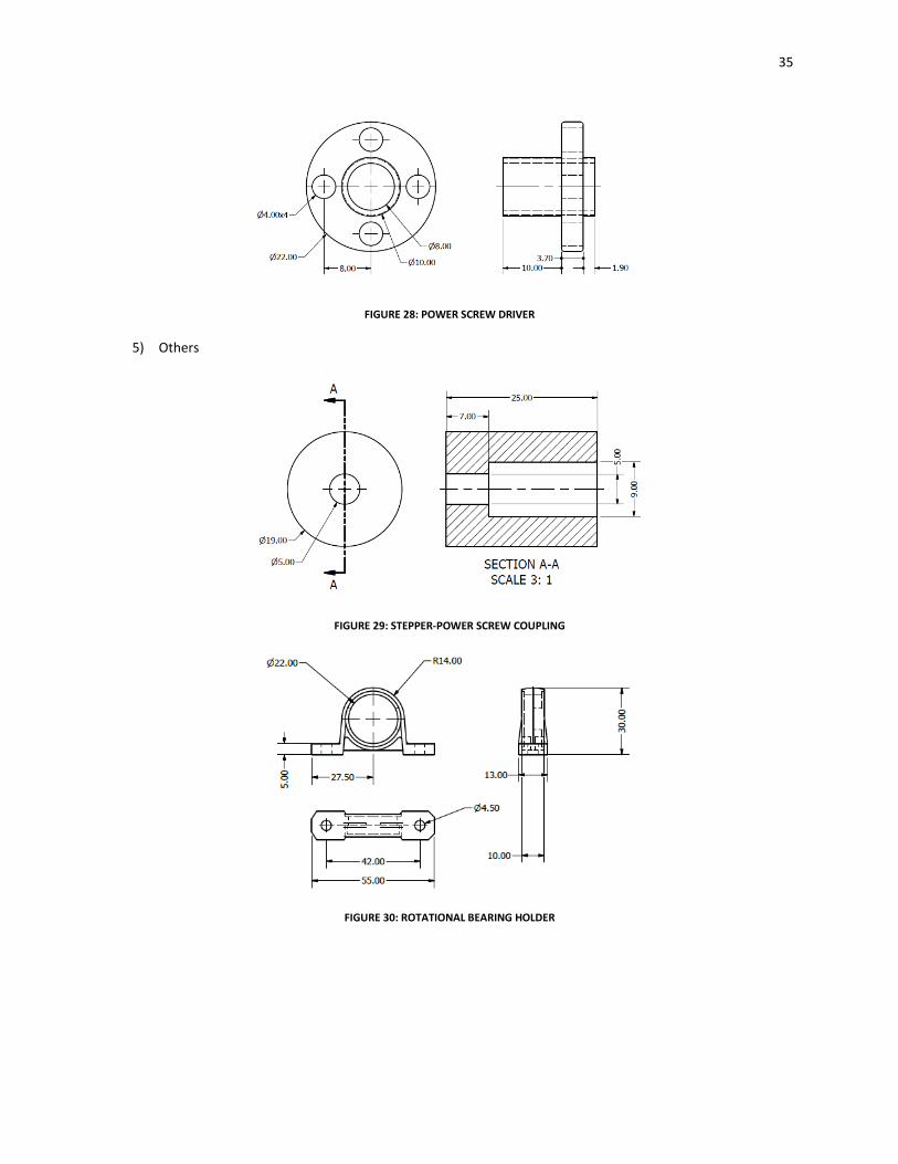
5) Others
FIGURE 29: STEPPER-POWER SCREW COUPLING
FIGURE 30: ROTATIONAL BEARING HOLDER
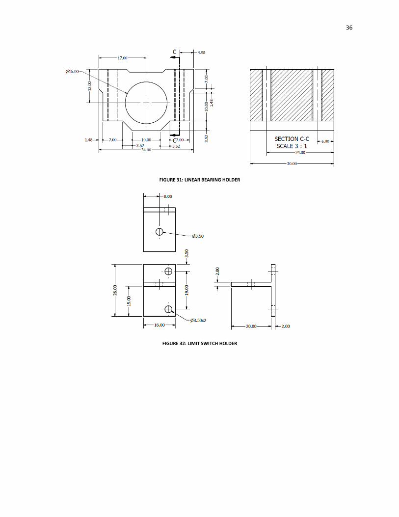
36
FIGURE 31: LINEAR BEARING HOLDER
FIGURE 32: LIMIT SWITCH HOLDER
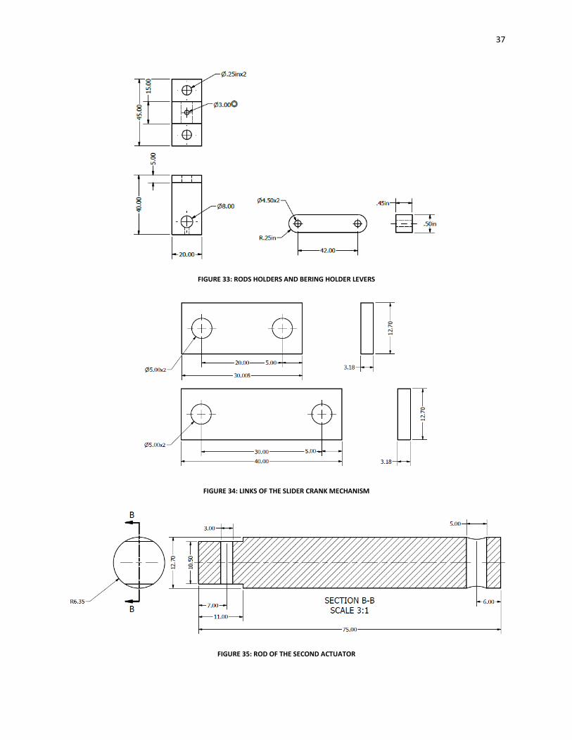
37
FIGURE 33: RODS HOLDERS AND BERING HOLDER LEVERS
FIGURE 34: LINKS OF THE SLIDER CRANK MECHANISM
FIGURE 35: ROD OF THE SECOND ACTUATOR
38
ELECTRIC/ELECTRONIC DOMAIN
The detailed design of the electronic components is the detailed description of the electronic components used
on the prototype and their respective wiring.
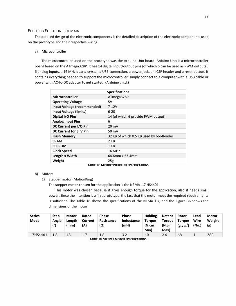
a) Microcontroller
The microcontroller used on the prototype was the Arduino Uno board. Arduino Uno is a microcontroller
board based on the ATmega328P. It has 14 digital input/output pins (of which 6 can be used as PWM outputs),
6 analog inputs, a 16 MHz quartz crystal, a USB connection, a power jack, an ICSP header and a reset button. It
contains everything needed to support the microcontroller; simply connect to a computer with a USB cable or
power with AC-to-DC adapter to get started. (Arduino , n.d.)
Specifications
Microcontroller ATmega328P
Operating Voltage 5V
Input Voltage (recommended) 7-12V
Input Voltage (limits) 6-20
Digital I/O Pins 14 (of which 6 provide PWM output)
Analog Input Pins 6
DC Current per I/O Pin 20 mA
DC Current for 3. V Pin 50 mA
Flash Memory 32 KB of which 0.5 KB used by bootloader
SRAM 2 KB
EEPROM 1 KB
Clock Speed 16 MHz
Length x Width 68.6mm x 53.4mm
Weight 25g TABLE 17: MICROCONTROLLER SPECIFICATIONS
b) Motors
1) Stepper motor (MotionKing)
The stepper motor chosen for the application is the NEMA 1.7 HS4401.
This motor was chosen because it gives enough torque for the application, also it needs small
power. Since the intention is a first prototype, the fact that the motor meet the required requirements
is sufficient. The Table 18 shows the specifications of the NEMA 1.7, and the Figure 36 shows the
dimensions of the motor.
Series Mode
Step Angle (°)
Motor Length (mm)
Rated Current (A)
Phase Resistance (Ω)
Phase Inductance (mH)
Holding Torque (N.cm Min)
Detent Torque (N.cm Max)
Rotor Torque
(g.c㎡)
Lead Wire (No.)
Motor Weight (g)
17HS4401 1.8 48 1.7 1.8 3.2 40 2.6 68 4 280 TABLE 18: STEPPER MOTOR SPECIFICATIONS
39
FIGURE 36: STEPPER MOTOR DIMENSIONS (MOTIONKING)
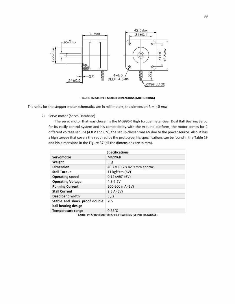
The units for the stepper motor schematics are in millimeters, the dimension 𝐿 = 40 𝑚𝑚
2) Servo motor (Servo Database)
The servo motor that was chosen is the MG996R High torque metal Gear Dual Ball Bearing Servo
for its easily control system and his compatibility with the Arduino platform, the motor comes for 2
different voltage set ups (4.8 V and 6 V), the set up chosen was 6V due to the power source. Also, it has
a high torque that covers the required by the prototype, his specifications can be found in the Table 19
and his dimensions in the Figure 37 (all the dimensions are in mm).
Specifications
Servomotor MG996R
Weight 55g
Dimension 40.7 x 19.7 x 42.9 mm approx.
Stall Torque 11 kgf*cm (6V)
Operating speed 0.14 s/60° (6V)
Operating Voltage 4.8-7.2V
Running Current 500-900 mA (6V)
Stall Current 2.5 A (6V)
Dead band width 5 𝜇𝑠
Stable and shock proof double ball bearing design
YES
Temperature range 0-55°C TABLE 19: SERVO MOTOR SPECIFICATIONS (SERVO DATABASE)
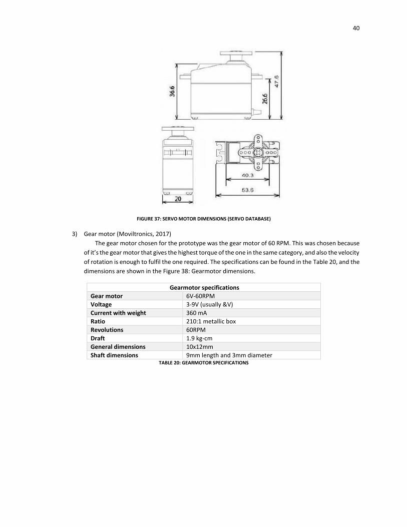
40
FIGURE 37: SERVO MOTOR DIMENSIONS (SERVO DATABASE)
3) Gear motor (Moviltronics, 2017)
The gear motor chosen for the prototype was the gear motor of 60 RPM. This was chosen because
of it’s the gear motor that gives the highest torque of the one in the same category, and also the velocity
of rotation is enough to fulfil the one required. The specifications can be found in the Table 20, and the
dimensions are shown in the Figure 38: Gearmotor dimensions.
Gearmotor specifications
Gear motor 6V-60RPM
Voltage 3-9V (usually &V)
Current with weight 360 mA
Ratio 210:1 metallic box
Revolutions 60RPM
Draft 1.9 kg-cm
General dimensions 10x12mm
Shaft dimensions 9mm length and 3mm diameter TABLE 20: GEARMOTOR SPECIFICATIONS
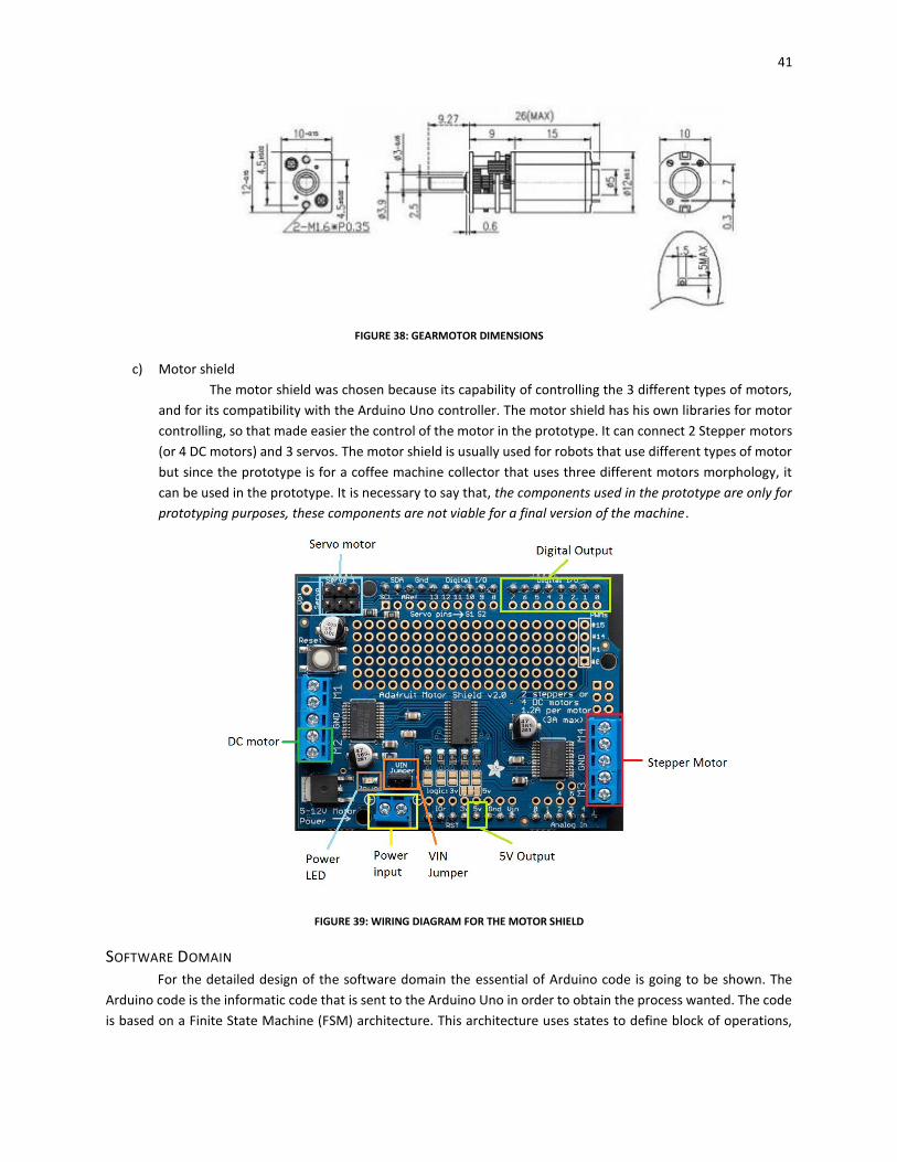
41
FIGURE 38: GEARMOTOR DIMENSIONS
c) Motor shield
The motor shield was chosen because its capability of controlling the 3 different types of motors,
and for its compatibility with the Arduino Uno controller. The motor shield has his own libraries for motor
controlling, so that made easier the control of the motor in the prototype. It can connect 2 Stepper motors
(or 4 DC motors) and 3 servos. The motor shield is usually used for robots that use different types of motor
but since the prototype is for a coffee machine collector that uses three different motors morphology, it
can be used in the prototype. It is necessary to say that, the components used in the prototype are only for
prototyping purposes, these components are not viable for a final version of the machine.
FIGURE 39: WIRING DIAGRAM FOR THE MOTOR SHIELD
SOFTWARE DOMAIN For the detailed design of the software domain the essential of Arduino code is going to be shown. The
Arduino code is the informatic code that is sent to the Arduino Uno in order to obtain the process wanted. The code
is based on a Finite State Machine (FSM) architecture. This architecture uses states to define block of operations,
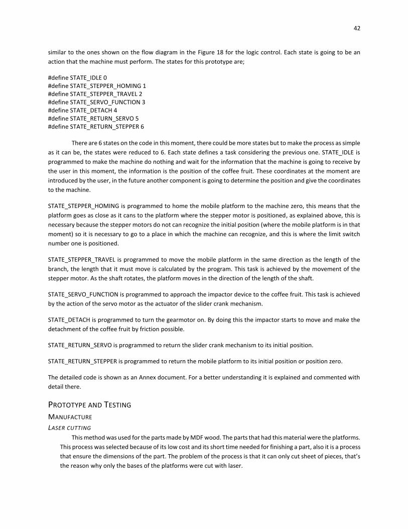
42
similar to the ones shown on the flow diagram in the Figure 18 for the logic control. Each state is going to be an
action that the machine must perform. The states for this prototype are;
#define STATE_IDLE 0 #define STATE_STEPPER_HOMING 1 #define STATE_STEPPER_TRAVEL 2 #define STATE_SERVO_FUNCTION 3 #define STATE_DETACH 4 #define STATE_RETURN_SERVO 5 #define STATE_RETURN_STEPPER 6
There are 6 states on the code in this moment, there could be more states but to make the process as simple
as it can be, the states were reduced to 6. Each state defines a task considering the previous one. STATE_IDLE is
programmed to make the machine do nothing and wait for the information that the machine is going to receive by
the user in this moment, the information is the position of the coffee fruit. These coordinates at the moment are
introduced by the user, in the future another component is going to determine the position and give the coordinates
to the machine.
STATE_STEPPER_HOMING is programmed to home the mobile platform to the machine zero, this means that the
platform goes as close as it cans to the platform where the stepper motor is positioned, as explained above, this is
necessary because the stepper motors do not can recognize the initial position (where the mobile platform is in that
moment) so it is necessary to go to a place in which the machine can recognize, and this is where the limit switch
number one is positioned.
STATE_STEPPER_TRAVEL is programmed to move the mobile platform in the same direction as the length of the
branch, the length that it must move is calculated by the program. This task is achieved by the movement of the
stepper motor. As the shaft rotates, the platform moves in the direction of the length of the shaft.
STATE_SERVO_FUNCTION is programmed to approach the impactor device to the coffee fruit. This task is achieved
by the action of the servo motor as the actuator of the slider crank mechanism.
STATE_DETACH is programmed to turn the gearmotor on. By doing this the impactor starts to move and make the
detachment of the coffee fruit by friction possible.
STATE_RETURN_SERVO is programmed to return the slider crank mechanism to its initial position.
STATE_RETURN_STEPPER is programmed to return the mobile platform to its initial position or position zero.
The detailed code is shown as an Annex document. For a better understanding it is explained and commented with
detail there.
PROTOTYPE AND TESTING
MANUFACTURE
LASER CUTTING
This method was used for the parts made by MDF wood. The parts that had this material were the platforms.
This process was selected because of its low cost and its short time needed for finishing a part, also it is a process
that ensure the dimensions of the part. The problem of the process is that it can only cut sheet of pieces, that’s
the reason why only the bases of the platforms were cut with laser.
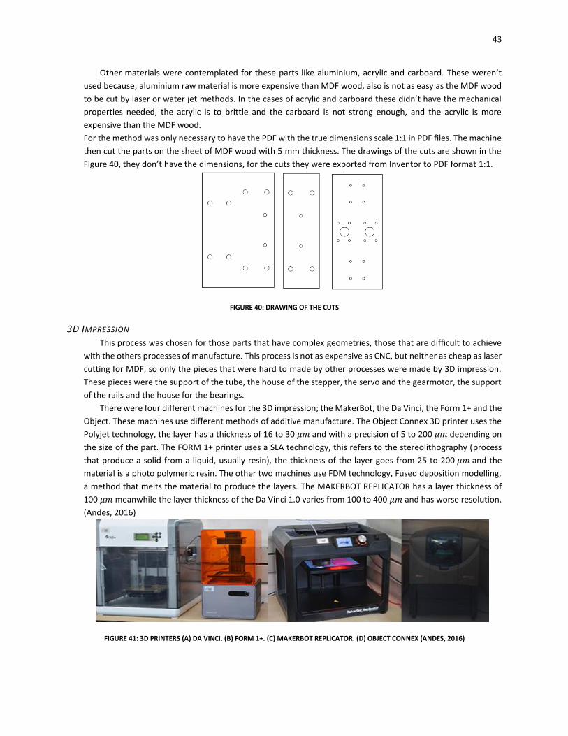
43
Other materials were contemplated for these parts like aluminium, acrylic and carboard. These weren’t
used because; aluminium raw material is more expensive than MDF wood, also is not as easy as the MDF wood
to be cut by laser or water jet methods. In the cases of acrylic and carboard these didn’t have the mechanical
properties needed, the acrylic is to brittle and the carboard is not strong enough, and the acrylic is more
expensive than the MDF wood.
For the method was only necessary to have the PDF with the true dimensions scale 1:1 in PDF files. The machine
then cut the parts on the sheet of MDF wood with 5 mm thickness. The drawings of the cuts are shown in the
Figure 40, they don’t have the dimensions, for the cuts they were exported from Inventor to PDF format 1:1.
FIGURE 40: DRAWING OF THE CUTS
3D IMPRESSION
This process was chosen for those parts that have complex geometries, those that are difficult to achieve
with the others processes of manufacture. This process is not as expensive as CNC, but neither as cheap as laser
cutting for MDF, so only the pieces that were hard to made by other processes were made by 3D impression.
These pieces were the support of the tube, the house of the stepper, the servo and the gearmotor, the support
of the rails and the house for the bearings.
There were four different machines for the 3D impression; the MakerBot, the Da Vinci, the Form 1+ and the
Object. These machines use different methods of additive manufacture. The Object Connex 3D printer uses the
Polyjet technology, the layer has a thickness of 16 to 30 𝜇𝑚 and with a precision of 5 to 200 𝜇𝑚 depending on
the size of the part. The FORM 1+ printer uses a SLA technology, this refers to the stereolithography (process
that produce a solid from a liquid, usually resin), the thickness of the layer goes from 25 to 200 𝜇𝑚 and the
material is a photo polymeric resin. The other two machines use FDM technology, Fused deposition modelling,
a method that melts the material to produce the layers. The MAKERBOT REPLICATOR has a layer thickness of
100 𝜇𝑚 meanwhile the layer thickness of the Da Vinci 1.0 varies from 100 to 400 𝜇𝑚 and has worse resolution.
(Andes, 2016)
FIGURE 41: 3D PRINTERS (A) DA VINCI. (B) FORM 1+. (C) MAKERBOT REPLICATOR. (D) OBJECT CONNEX (ANDES, 2016)
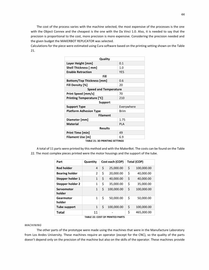
44
The cost of the process varies with the machine selected, the most expensive of the processes is the one
with the Object Connex and the cheapest is the one with the Da Vinci 1.0. Also, it is needed to say that the
precision is proportional to the cost, more precision is more expensive. Considering the precision needed and
the given budget the MAKERBOT REPLICATOR was selected.
Calculations for the piece were estimated using Cura software based on the printing setting shown on the Table
21.
Quality
Layer Height [mm] 0.1
Shell Thickness [ mm] 1.0
Enable Retraction YES
Fill
Bottom/Top Thickness [mm] 0.6
Fill Density [%] 20
Speed and Temperature
Print Speed [mm/s] 70
Printing Temperature [°C] 210
Support
Support Type Everywhere
Platform Adhesion Type Brim
Filament
Diameter [mm] 1.75
Material PLA
Results
Print Time [min] 49
Filament Use [m] 6.9 TABLE 21: 3D PRINTING SETTINGS
A total of 11 parts were printed by this method and with the MakerBot. The costs can be found on the Table
22. The most complex pieces printed were the motor housings and the support of the tube.
Part Quantity Cost each (COP) Total (COP)
Rod holder 4 $ 25,000.00 $ 100,000.00
Bearing holder 2 $ 20,000.00 $ 40,000.00
Stepper holder 1 1 $ 40,000.00 $ 40,000.00
Stepper holder 2 1 $ 35,000.00 $ 35,000.00
Servomotor holder
1 $ 100,000.00 $ 100,000.00
Gearmotor holder
1 $ 50,000.00 $ 50,000.00
Tube support 1 $ 100,000.00 $ 100,000.00
Total 11 - $ 465,000.00
TABLE 22: COST OF PRINTED PARTS
MACHINING
The other parts of the prototype were made using the machines that were in the Manufacture Laboratory
from Los Andes University. These machines require an operator (except for the CNC), so the quality of the parts
doesn’t depend only on the precision of the machine but also on the skills of the operator. These machines provide

45
processes of drilling, milling. The cutting of parts was made by a handsaw. These pieces didn’t have so good
tolerances because it depended on the skills of the manufacturer. The pieces made by these processes costed only
the value of the raw material. The pieces and the cost of the raw material was less than 30 USD.
PROTOTYPE
After manufacture and acquisition of the pieces, the assemble had to be made. The assemble drawings can
be found on the Appendix. All the parts were connected by bolts with their screws, because its facility for assembling
and dissembling and its strength, this was the joining selected. The prototype is shown in the Figure 42.
FIGURE 42: PHOTOS OF THE PROTOTYPE
TESTING The test of the machine was made using the code developed for the final movement, the velocities were
changed to obtain the values of duration for the machine process. Each of the actuators were tested separately, this
was made to perceive any flaw that had each movement. The displacements were timed by chronometer, and they
were measured with the Software Tracker. This process was applied for the 2 longitudinal movements, the one done
by the stepper and by the servo and the slider crankshaft mechanism. The rotational movement was checked by a
stroboscope with a mark placed on the shaft of the DC gearmotor, however, the movement was longer to obtain a
more precise value for the RPM of the movement, so this movement was tested with another code of Arduino.
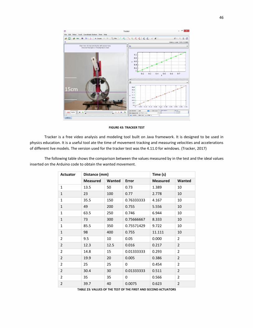
46
FIGURE 43: TRACKER TEST
Tracker is a free video analysis and modeling tool built on Java framework. It is designed to be used in
physics education. It is a useful tool ate the time of movement tracking and measuring velocities and accelerations
of different live models. The version used for the tracker test was the 4.11.0 for windows. (Tracker, 2017)
The following table shows the comparison between the values measured by in the test and the ideal values
inserted on the Arduino code to obtain the wanted movement.
Actuator Distance (mm) Time (s)
Measured Wanted Error Measured Wanted
1 13.5 50 0.73 1.389 10
1 23 100 0.77 2.778 10
1 35.5 150 0.76333333 4.167 10
1 49 200 0.755 5.556 10
1 63.5 250 0.746 6.944 10
1 73 300 0.75666667 8.333 10
1 85.5 350 0.75571429 9.722 10
1 98 400 0.755 11.111 10
2 9.5 10 0.05 0.000 2
2 12.3 12.5 0.016 0.217 2
2 14.8 15 0.01333333 0.293 2
2 19.9 20 0.005 0.386 2
2 25 25 0 0.454 2
2 30.4 30 0.01333333 0.511 2
2 35 35 0 0.566 2
2 39.7 40 0.0075 0.623 2
TABLE 23: VALUES OF THE TEST OF THE FIRST AND SECOND ACTUATORS
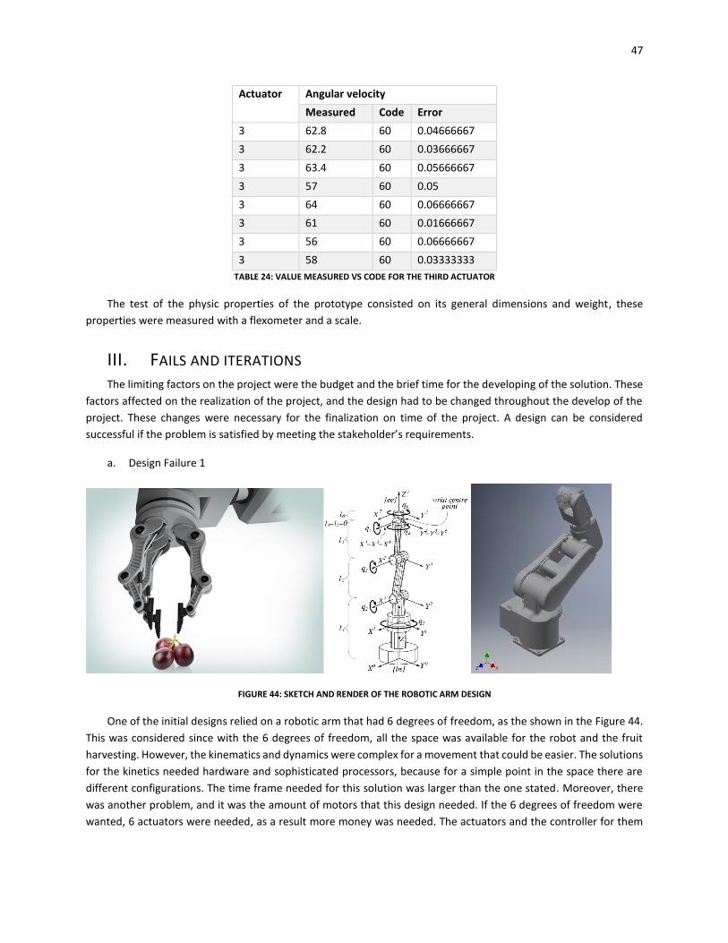
47
Actuator Angular velocity
Measured Code Error
3 62.8 60 0.04666667
3 62.2 60 0.03666667
3 63.4 60 0.05666667
3 57 60 0.05
3 64 60 0.06666667
3 61 60 0.01666667
3 56 60 0.06666667
3 58 60 0.03333333
TABLE 24: VALUE MEASURED VS CODE FOR THE THIRD ACTUATOR
The test of the physic properties of the prototype consisted on its general dimensions and weight, these
properties were measured with a flexometer and a scale.
III. FAILS AND ITERATIONS The limiting factors on the project were the budget and the brief time for the developing of the solution. These
factors affected on the realization of the project, and the design had to be changed throughout the develop of the
project. These changes were necessary for the finalization on time of the project. A design can be considered
successful if the problem is satisfied by meeting the stakeholder’s requirements.
a. Design Failure 1
FIGURE 44: SKETCH AND RENDER OF THE ROBOTIC ARM DESIGN
One of the initial designs relied on a robotic arm that had 6 degrees of freedom, as the shown in the Figure 44.
This was considered since with the 6 degrees of freedom, all the space was available for the robot and the fruit
harvesting. However, the kinematics and dynamics were complex for a movement that could be easier. The solutions
for the kinetics needed hardware and sophisticated processors, because for a simple point in the space there are
different configurations. The time frame needed for this solution was larger than the one stated. Moreover, there
was another problem, and it was the amount of motors that this design needed. If the 6 degrees of freedom were
wanted, 6 actuators were needed, as a result more money was needed. The actuators and the controller for them
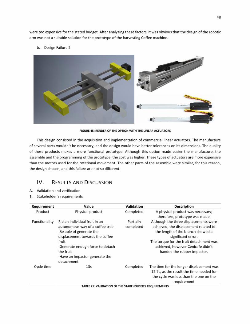
48
were too expensive for the stated budget. After analyzing these factors, it was obvious that the design of the robotic
arm was not a suitable solution for the prototype of the harvesting Coffee machine.
b. Design Failure 2
FIGURE 45: RENDER OF THE OPTION WITH THE LINEAR ACTUATORS
This design consisted in the acquisition and implementation of commercial linear actuators. The manufacture
of several parts wouldn’t be necessary, and the design would have better tolerances on its dimensions. The quality
of these products makes a more functional prototype. Although this option made easier the manufacture, the
assemble and the programming of the prototype, the cost was higher. These types of actuators are more expensive
than the motors used for the rotational movement. The other parts of the assemble were similar, for this reason,
the design chosen, and this failure are not so different.
IV. RESULTS AND DISCUSSION A. Validation and verification
1. Stakeholder’s requirements
Requirement Value Validation Description
Product Physical product Completed A physical product was necessary; therefore, prototype was made.
Functionality Rip an individual fruit in an autonomous way of a coffee tree -Be able of generate the displacement towards the coffee fruit -Generate enough force to detach the fruit -Have an impactor generate the detachment
Partially completed
Although the three displacements were achieved, the displacement related to
the length of the branch showed a significant error.
The torque for the fruit detachment was achieved, however Cenicafe didn’t
handed the rubber impactor.
Cycle time 13s Completed The time for the longer displacement was 12.7s, as the result the time needed for the cycle was less than the one on the
requirement TABLE 25: VALIDATION OF THE STAKEHOLDER'S REQUIREMENTS
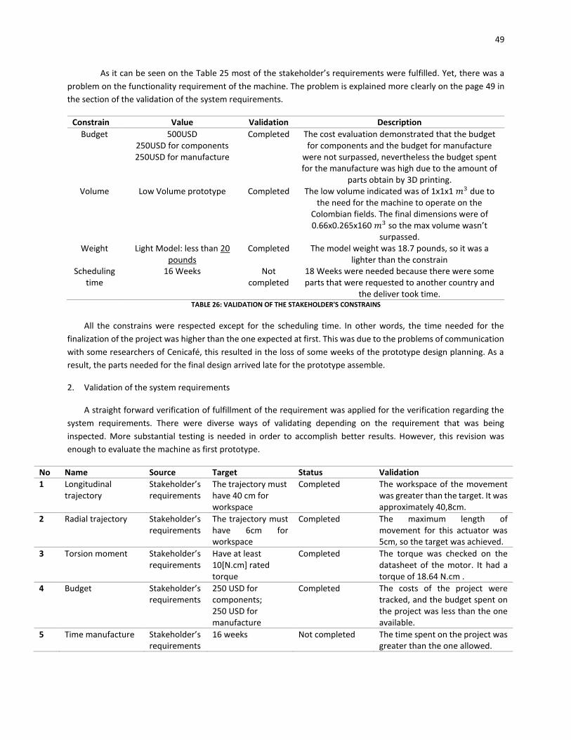
49
As it can be seen on the Table 25 most of the stakeholder’s requirements were fulfilled. Yet, there was a
problem on the functionality requirement of the machine. The problem is explained more clearly on the page 49 in
the section of the validation of the system requirements.
Constrain Value Validation Description
Budget 500USD 250USD for components 250USD for manufacture
Completed The cost evaluation demonstrated that the budget for components and the budget for manufacture
were not surpassed, nevertheless the budget spent for the manufacture was high due to the amount of
parts obtain by 3D printing. Volume Low Volume prototype Completed The low volume indicated was of 1x1x1 𝑚3 due to
the need for the machine to operate on the Colombian fields. The final dimensions were of 0.66x0.265x160 𝑚3 so the max volume wasn’t
surpassed. Weight Light Model: less than 20
pounds Completed The model weight was 18.7 pounds, so it was a
lighter than the constrain Scheduling
time 16 Weeks Not
completed 18 Weeks were needed because there were some parts that were requested to another country and
the deliver took time. TABLE 26: VALIDATION OF THE STAKEHOLDER'S CONSTRAINS
All the constrains were respected except for the scheduling time. In other words, the time needed for the
finalization of the project was higher than the one expected at first. This was due to the problems of communication
with some researchers of Cenicafé, this resulted in the loss of some weeks of the prototype design planning. As a
result, the parts needed for the final design arrived late for the prototype assemble.
2. Validation of the system requirements
A straight forward verification of fulfillment of the requirement was applied for the verification regarding the
system requirements. There were diverse ways of validating depending on the requirement that was being
inspected. More substantial testing is needed in order to accomplish better results. However, this revision was
enough to evaluate the machine as first prototype.
No Name Source Target Status Validation
1 Longitudinal trajectory
Stakeholder’s requirements
The trajectory must have 40 cm for workspace
Completed The workspace of the movement was greater than the target. It was approximately 40,8cm.
2 Radial trajectory Stakeholder’s requirements
The trajectory must have 6cm for workspace
Completed The maximum length of movement for this actuator was 5cm, so the target was achieved.
3 Torsion moment Stakeholder’s requirements
Have at least 10[N.cm] rated torque
Completed The torque was checked on the datasheet of the motor. It had a torque of 18.64 N.cm .
4 Budget Stakeholder’s requirements
250 USD for components; 250 USD for manufacture
Completed The costs of the project were tracked, and the budget spent on the project was less than the one available.
5 Time manufacture Stakeholder’s requirements
16 weeks Not completed The time spent on the project was greater than the one allowed.
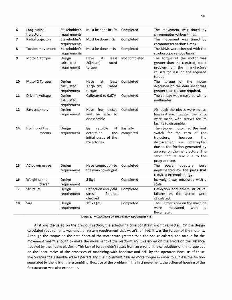
50
6 Longitudinal trajectory
Stakeholder’s requirements
Must be done in 10s Completed The movement was timed by chronometer various times.
7 Radial trajectory Stakeholder’s requirements
Must be done in 2s Completed The movement was timed by chronometer various times.
8 Torsion movement Stakeholder’s requirements
Must be done in 1s Completed The RPMs were checked with the stroboscope various times.
9 Motor 1 Torque Design calculated requirement
Have at least 20[N.cm] rated torque
Not completed The torque of the motor was greater than the required, but a problem on the manufacture caused the rise on the required torque.
10 Motor 2 Torque Design calculated requirement
Have at least 177[N.cm] rated torque
Completed The torque of the motor described on the data sheet was greater than the one required.
11 Driver’s Voltage Design calculated requirement
Calibrated to 0.67V Completed The voltage was measured with a multimeter.
12 Easy assembly Design requirement
Have few pieces and be able to disassemble
Completed Although the pieces were not as few as it was intended, the joints were made with screws for its facility to dissemble.
14 Homing of the motors
Design requirement
Be capable of determine the initial ceros of the trajectories
Partially completed
The stepper motor had the limit switch for the zero of the trajectory, however the displacement was interrupted due to the friction generated by an error on the manufacture. The servo had its zero due to the programming.
15 AC power usage Design requirement
Have connection to the main power grid
Completed The power adapters were implemented for the parts that required external energy.
16 Weight of the driver
Design requirement
3 [kg] Completed Its weight was measured with a scale.
17 Structure Design requirement
Deflection and yield stress failures checked
Completed Deflection and others structural failures on the system were calculated.
18 Size Design requirement
1x1x1 [m] Completed The 3 dimensions on the machine were measured with a flexometer.
TABLE 27: VALIDATION OF THE SYSTEM REQUIREMENTS
As it was discussed on the previous section, the scheduling time constrain wasn’t respected. On the design
calculated requirements was another system requirement that wasn’t fulfilled, it was the torque of the motor 1.
Although the torque on the data sheet of the motor was greater than the one calculated, the torque for the
movement wasn’t enough to make the movement of the platform and this ended on the errors on the distance
traveled by the mobile platform. This lack of torque didn’t result from an error on the calculations of the torque but
on the inaccuracies of the processes of machining with handsaw and drill by the operator. Because of these
inaccuracies the assemble wasn’t perfect and the movement needed more torque in order to surpass the friction
generated by the fails of the assembling. Because of the problem in the first movement, the action of housing of the
first actuator was also erroneous.
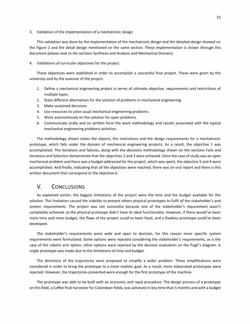
51
3. Validation of the implementation of a mechatronic design
This validation was done by the implementation of the mechatronic design and the detailed design showed on
the Figure 2 and the detail design mentioned on the same section. These implementation is shown through this
document (please look to the sections Synthesis and Analysis and Mechanical Domain).
4. Validations of curricular objectives for the project.
These objectives were stablished in order to accomplish a successful final project. These were given by the
university and by the assessor of the project.
1. Define a mechanical engineering project in terms of ultimate objective, requirements and restrictions of
multiple types.
2. State different alternatives for the solution of problems in mechanical engineering.
3. Make sustained decisions.
4. Use resources to solve usual mechanical engineering problems.
5. Work autonomously on the solution for open problems.
6. Communicate orally and on written form the work methodology and results associated with the typical
mechanical engineering problems activities.
The methodology shown states the objects, the restrictions and the design requirements for a mechatronic
prototype, which falls under the domain of mechanical engineering projects. As a result, the objective 1 was
accomplished. The iterations and failures, along with the decisions methodology shown on the sections Fails and
iterations and Selection demonstrate that the objectives 2 and 3 were achieved. Since the case of study was an open
mechanical problem and there was a budget addressed for the project, which was spent, the objective 5 and 4 were
accomplished. And finally, indicating that all the objectives were reached, there was an oral report and there is this
written document that correspond to the objective 6.
V. CONCLUSIONS As explained earlier, the biggest limitations of the project were the time and the budget available for the
solution. This limitation caused the inability to present others physical prototypes to fulfil all the stakeholder’s and
system requirements. The project was not successful because one of the stakeholder’s requirement wasn’t
completely achieved, so the physical prototype didn’t have its ideal functionality. However, if there would’ve been
more time and more budget, the flaws of the project could’ve been fixed, and a flawless prototype could’ve been
developed.
The stakeholder’s requirements were wide and open to decision, for this reason more specific system
requirements were formulated. Some options were rejected considering the stakeholder’s requirements, as is the
case of the robotic arm option, other options were rejected by the decision evaluation on the Pugh’s diagram. A
single prototype was made due to the limitations of time and budget.
The directions of the trajectories were proposed to simplify a wider problem. These simplifications were
considered in order to bring the prototype to a more realistic goal. As a result, more elaborated prototypes were
rejected. However, the trajectories presented were enough for the first prototype of the machine.
The prototype was able to be built with an economic and rapid procedure. The design process of a prototype
on this field, a Coffee fruit harvester for Colombian fields, was achieved in less time than 5 months and with a budget
52
lesser than 500 USD. Moreover, as it is shown on the background research, there haven’t been a lot of investigation
on this kind of machines, so there is an unstudied area.
More concise conclusions are presented beneath, these conclusions allude to the three different fields of the
mechatronic evaluation of the machine.
1. Mechanical field
The physical means chosen for the prototype weren’t absolutely the bests. As a result, the machine didn’t work
properly. However, this problem could be fixed with a better manufacturing plan or a strong motor for the first
trajectory.
On the other hand, the parts and components were obtained with economic and rapid methods. The
manufacturing methods used were standard and from easy access, and complex parts were avoided to obtain a
simple prototype. Maybe there could have been better physical means for the fulfilling of the trajectories presented,
but they were too expensive to apply them to the machine.
The tests made on the machine for the other 2 mechanisms, taking out the mechanism of longitudinal trajectory,
showed excellent results. The highest error percentage for the slider crank mechanism movement was 5% and the
highest error for the gearmotor RPMs was 6.66%.
The joints used on the prototype made it easy to the assemble and dissemble. However, if the prototype is
wanted to improve to a machine, another typology of joints need to be applied. The same goes for the motors, the
motors selected for the prototype were the ones that fulfil the minimum requirements, and the ones that can be
easily found on the market, the standard. Nevertheless, if a final product is wanted, better motors need to be
implemented.
2. Electronic components
The electric components demonstrate to be not trustworthy. Cheap electronics are not reliable, they are easily
damaged, and they don’t have a large life span. The board showed a lack of voltage capacity that had to be replaced
with another connection to the AC power source. An important clarification must be made, Arduino is an open
source, as a result an Arduino board can be built by any manufacturer. The one used on the prototype is not originally
built by Arduino, so its quality is lower. The cables and connections are not organized and soldered, so there is a risk
for disconnection. This also does not provide good aesthetics. In order to fix this problem Cables drawings could be
made.
The limit switch were the only sensors used on the prototype, they functioned perfectly. On the case of the
actuators, 2 of them worked fine, neither showed flaws or problems at their performance. However, the stepper
showed an error, at the moment of the trajectory, there were steps that were rejected. This was due to the high
friction between the rotating shaft and the platform drivers. That factor increased the torque needed in order to
make the movement, that was the reason why the first trajectory presented a high percentage of error.
Arduino is one of the greatest components when it comes to prototyping, due to its facility and its friendly
interface. Nonetheless, when it comes to a final product, Arduino is not enough, and another type of circuits needed
to be implemented. These electronic components could be improved severally.
3. Software
53
The Software is extremely necessary for the mechatronic machines that are being developed since some years
ago. The integration of this domain with the mechanical and electrical is the one that generate the mechatronic
domain. The software is the one that indicates the machine how it must work, without the software the machine
wouldn’t be able to operate. The code showed to be functional, as a result the machine worked in the way that it
was expected to. However, the failure produced by the first actuator wasn’t due to a mistake on the software. A
more complex code could’ve been written but it wasn’t necessary.
VI. FUTURE WORKS There is a lot of work that could be applied to this project, this further work can be divided in two different categories.
1. Iteration for the prototype.
2. Creation and integration with other modules.
The iterations for the prototypes can be divided in the same three domains that were explained through this
document;
a. Mechanical domain
The platforms are built on low cost wood and manufactured by low cost processes, a better material could
be selected and a better process in order to obtain more reliable parts. The platform driver could be done by a
more precise manufacturing process to obtain better parts and fix the problem of the generated friction that
affects the first trajectory. Another way to fix the problem on the first trajectory is to change the mechanism
that generates it for one available in the market, for example a linear actuator. The same way could be used for
the second mechanism in order to improve the error and improve the life span of the mechanism.
The rubber impactor is needed for the machine to achieve the task that it was designed for. This rubber
could be created or asked to Cenicafé, who were the ones that developed the investigation around it. The
material of the tube was aluminium, which is a heavy material. It could be replaced with a tube of PVC to reduce
the weight of the prototype.
The machine, due to the budget and the time, was designed only to detach one fruit from the branch.
However, the plan is to implement more mechanisms of with the second and third trajectory to in the travel of
the first mechanism be able to harvest all the mature fruits on the branch.
The design of the prototype could be improved in order to conceive a more hermetic prototype, this could
protect the motors and other components on rainy days and other situations.
b. Electronic domain
On the electronic domain, as it was said on the mechanical domain, the implementation of more
mechanisms that contain the second and third mechanism are necessary to obtain a better product. As a result,
more actuators (motors) are needed, and this at the same time indicates that more drivers and motor shields
are required.
Secondly, an important further work on this domain is the planning of the cables management and secure
the connections of the components. This in order to have a more aesthetic product and as the same time
reliable.
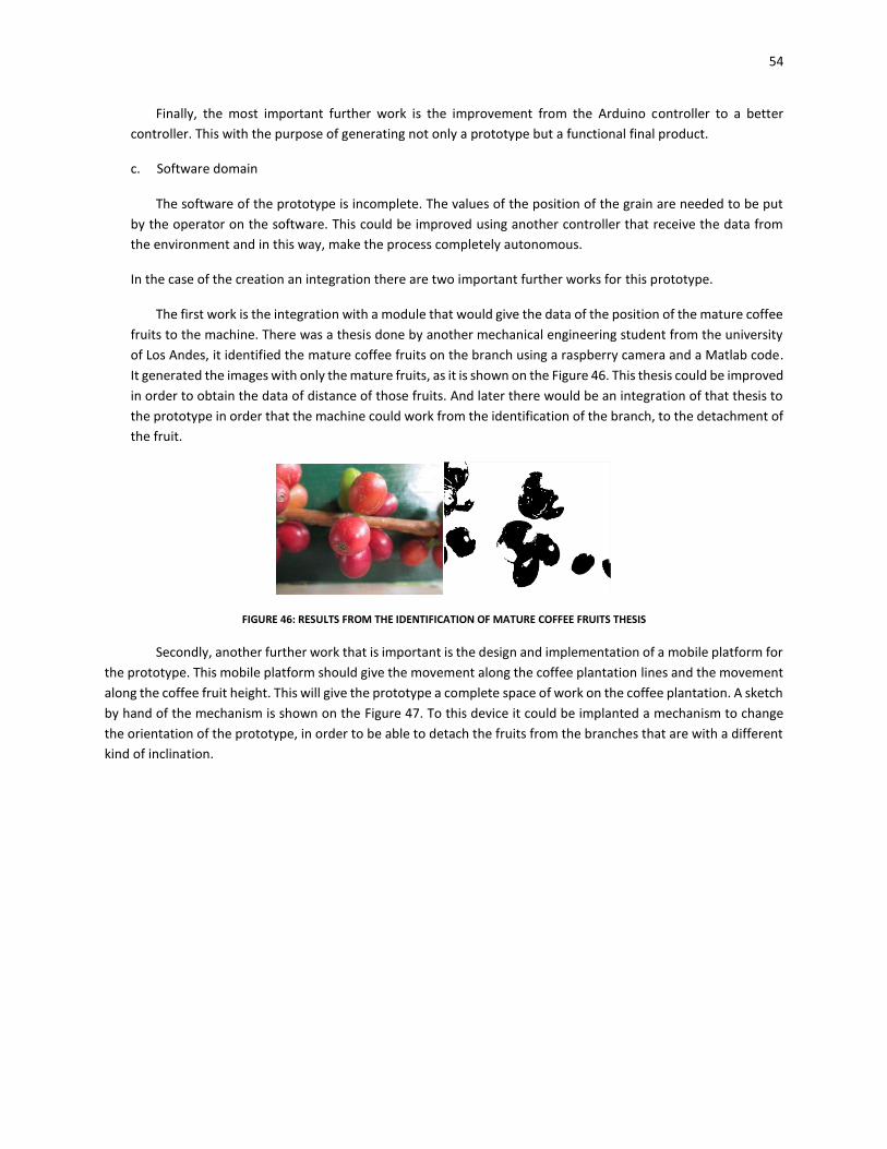
54
Finally, the most important further work is the improvement from the Arduino controller to a better
controller. This with the purpose of generating not only a prototype but a functional final product.
c. Software domain
The software of the prototype is incomplete. The values of the position of the grain are needed to be put
by the operator on the software. This could be improved using another controller that receive the data from
the environment and in this way, make the process completely autonomous.
In the case of the creation an integration there are two important further works for this prototype.
The first work is the integration with a module that would give the data of the position of the mature coffee
fruits to the machine. There was a thesis done by another mechanical engineering student from the university
of Los Andes, it identified the mature coffee fruits on the branch using a raspberry camera and a Matlab code.
It generated the images with only the mature fruits, as it is shown on the Figure 46. This thesis could be improved
in order to obtain the data of distance of those fruits. And later there would be an integration of that thesis to
the prototype in order that the machine could work from the identification of the branch, to the detachment of
the fruit.
FIGURE 46: RESULTS FROM THE IDENTIFICATION OF MATURE COFFEE FRUITS THESIS
Secondly, another further work that is important is the design and implementation of a mobile platform for
the prototype. This mobile platform should give the movement along the coffee plantation lines and the movement
along the coffee fruit height. This will give the prototype a complete space of work on the coffee plantation. A sketch
by hand of the mechanism is shown on the Figure 47. To this device it could be implanted a mechanism to change
the orientation of the prototype, in order to be able to detach the fruits from the branches that are with a different
kind of inclination.
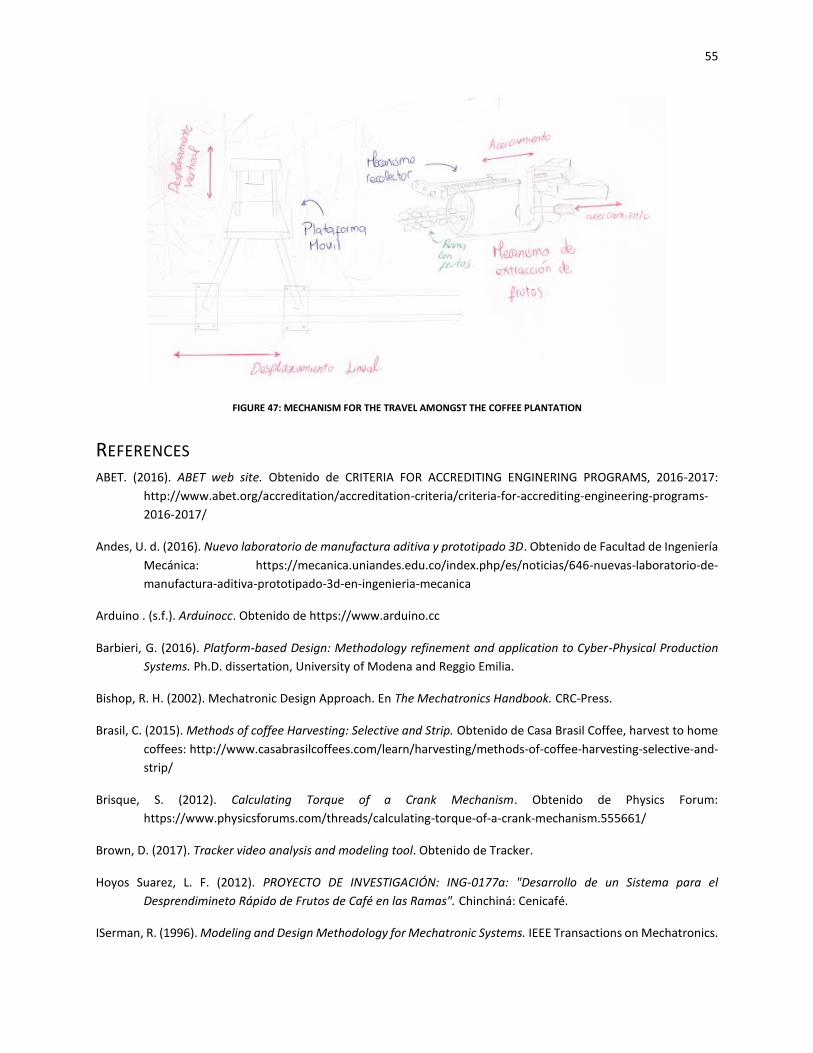
55
FIGURE 47: MECHANISM FOR THE TRAVEL AMONGST THE COFFEE PLANTATION
REFERENCES ABET. (2016). ABET web site. Obtenido de CRITERIA FOR ACCREDITING ENGINERING PROGRAMS, 2016-2017:
http://www.abet.org/accreditation/accreditation-criteria/criteria-for-accrediting-engineering-programs-
2016-2017/
Andes, U. d. (2016). Nuevo laboratorio de manufactura aditiva y prototipado 3D. Obtenido de Facultad de Ingeniería
Mecánica: https://mecanica.uniandes.edu.co/index.php/es/noticias/646-nuevas-laboratorio-de-
manufactura-aditiva-prototipado-3d-en-ingenieria-mecanica
Arduino . (s.f.). Arduinocc. Obtenido de https://www.arduino.cc
Barbieri, G. (2016). Platform-based Design: Methodology refinement and application to Cyber-Physical Production
Systems. Ph.D. dissertation, University of Modena and Reggio Emilia.
Bishop, R. H. (2002). Mechatronic Design Approach. En The Mechatronics Handbook. CRC-Press.
Brasil, C. (2015). Methods of coffee Harvesting: Selective and Strip. Obtenido de Casa Brasil Coffee, harvest to home
coffees: http://www.casabrasilcoffees.com/learn/harvesting/methods-of-coffee-harvesting-selective-and-
strip/
Brisque, S. (2012). Calculating Torque of a Crank Mechanism. Obtenido de Physics Forum:
https://www.physicsforums.com/threads/calculating-torque-of-a-crank-mechanism.555661/
Brown, D. (2017). Tracker video analysis and modeling tool. Obtenido de Tracker.
Hoyos Suarez, L. F. (2012). PROYECTO DE INVESTIGACIÓN: ING-0177a: "Desarrollo de un Sistema para el
Desprendimineto Rápido de Frutos de Café en las Ramas". Chinchiná: Cenicafé.
ISerman, R. (1996). Modeling and Design Methodology for Mechatronic Systems. IEEE Transactions on Mechatronics.
56
J.L, M. L. (s.f.). Engineering Mechanics Dynamics . Wiley.
León Moreno, E., & Álvarez Mejía, F. (2015). A Portable device to assist in the Harvest of coffee in Colombia. Medellín:
Universidad Nacional sede Medellín.
MotionKing. (s.f.). HB Stepper Motor Catalog. Motor Industry Co. Ltd.
Moviltronics. (2017). Gearmotor 60RPM description. Obtenido de Moviltronics:
https://moviltronics.com.co/motores-reductores/194-motor-reductor-6v-60-
rpm.html?search_query=60+RPM&results=10
Nisbet, R. G. (9th Edition). Deflection and Stiffness. En Shigley's Mechanical Engineering Design. McGraw-Hill.
Nisbett, R. G. (s.f.). Fatigue Failure Resulting from Variable Loading. En Shigley's Mechanical Engineering Design (pág.
256). McGraw-Hill.
Nisbett, R. G. (s.f.). Screws, Fasteners, and the Design of Nonpermanent Joints. En Shigley's Mechanical Engineering
Design (pág. 409). McGraw-Hill.
Nisbett, R. G. (s.f.). Shafts and Shafts Components. En Shigley's Mechanical Engineering Design (pág. 359). McGraw-
Hill.
Norton, R. L. (s.f.). Analytical Linkage Synthesis. En Design of Machinery (pág. 188). Worcester, Massachusetts:
McGraw-Hill.
Norton, R. L. (s.f.). The Design Process. En Design of MAchinery. Worcester, Massachusetts: McGraw-Hill.
Oliveros Tascón, C. E., & Sanz-Uribe, J. R. (2011). Engineering and Coffee in Colombia. Bogotá D.C: Revista de
ingeniería Universidad de los Andes.
Servo Database. (s.f.). MG996R High torque metal Gear Dual Ball Bearing Servo. Servo Database: Servo specifications
and reviews.
Tracker. (2017). Tracker Home. Obtenido de Tracker Video Analysis and Modeling Tool: https://physlets.org/tracker/
Ugural, A. C. (s.f.). Mechanical Design, An Integrated Approach. McGraw-Hill.
Wentzell, T. H. (2004). Machine Design. Thomson Delmar Lerning.
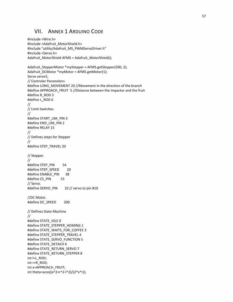
57
VII. ANNEX 1 ARDUINO CODE #include <Wire.h> #include <Adafruit_MotorShield.h> #include "utility/Adafruit_MS_PWMServoDriver.h" #include <Servo.h> Adafruit_MotorShield AFMS = Adafruit_MotorShield(); Adafruit_StepperMotor *myStepper = AFMS.getStepper(200, 2); Adafruit_DCMotor *myMotor = AFMS.getMotor(1); Servo servo1; // Controler Parameters #define LONG_MOVEMENT 20 //Movement in the direction of the branch #define APPROACH_FRUIT 5 //Distance between the impactor and the fruit #define R_ROD 3 #define L_ROD 6 // // Limit Switches. // #define START_LIM_PIN 3 #define END_LIM_PIN 2 #define RELAY 15 // // Defines steps for Stepper // #define STEP_TRAVEL 20 // Stepper. // #define STEP_PIN 54 #define STEP_SPEED 20 #define ENABLE_PIN 38 #define CS_PIN 53 // Servo. #define SERVO_PIN 10 // servo to pin #10 //DC Motor. #define DC_SPEED 200 // Defines State Machine // #define STATE_IDLE 0 #define STATE_STEPPER_HOMING 1 #define STATE_WAITS_FOR_COFFEE 3 #define STATE_STEPPER_TRAVEL 4 #define STATE_SERVO_FUNCTION 5 #define STATE_DETACH 6 #define STATE_RETURN_SERVO 7 #define STATE_RETURN_STEPPER 8 int l=L_ROD; int r=R_ROD; int x=APPROACH_FRUIT; int theta=acos((x^2+r^2-l^2)/(2*x*r));
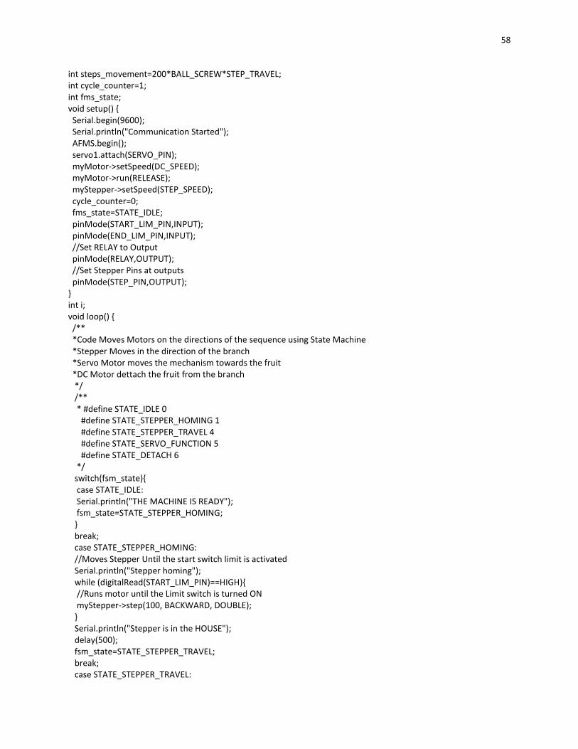
58
int steps_movement=200*BALL_SCREW*STEP_TRAVEL; int cycle_counter=1; int fms_state; void setup() { Serial.begin(9600); Serial.println("Communication Started"); AFMS.begin(); servo1.attach(SERVO_PIN); myMotor->setSpeed(DC_SPEED); myMotor->run(RELEASE); myStepper->setSpeed(STEP_SPEED); cycle_counter=0; fms_state=STATE_IDLE; pinMode(START_LIM_PIN,INPUT); pinMode(END_LIM_PIN,INPUT); //Set RELAY to Output pinMode(RELAY,OUTPUT); //Set Stepper Pins at outputs pinMode(STEP_PIN,OUTPUT); } int i; void loop() { /** *Code Moves Motors on the directions of the sequence using State Machine *Stepper Moves in the direction of the branch *Servo Motor moves the mechanism towards the fruit *DC Motor dettach the fruit from the branch */ /** * #define STATE_IDLE 0 #define STATE_STEPPER_HOMING 1 #define STATE_STEPPER_TRAVEL 4 #define STATE_SERVO_FUNCTION 5 #define STATE_DETACH 6 */ switch(fsm_state){ case STATE_IDLE: Serial.println("THE MACHINE IS READY"); fsm_state=STATE_STEPPER_HOMING; } break; case STATE_STEPPER_HOMING: //Moves Stepper Until the start switch limit is activated Serial.println("Stepper homing"); while (digitalRead(START_LIM_PIN)==HIGH){ //Runs motor until the Limit switch is turned ON myStepper->step(100, BACKWARD, DOUBLE); } Serial.println("Stepper is in the HOUSE"); delay(500); fsm_state=STATE_STEPPER_TRAVEL; break; case STATE_STEPPER_TRAVEL:
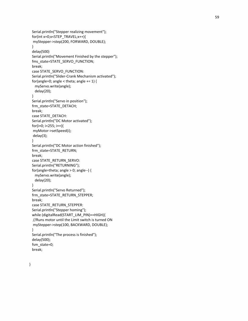
59
Serial.println("Stepper realizing movement"); for(int x=0;x<STEP_TRAVEL;x++){ myStepper->step(200, FORWARD, DOUBLE); } delay(500) Serial.println("Movement Finished by the stepper"); fms_state=STATE_SERVO_FUNCTION; break; case STATE_SERVO_FUNCTION: Serial.println("Slider-Crank Mechanism activated"); for(angle=0; angle < theta; angle += 1) { myServo.write(angle); delay(20); } Serial.println("Servo in position"); frm_state=STATE_DETACH; break; case STATE_DETACH: Serial.println("DC Motor activated"); for(i=0; i<255; i++){ myMotor->setSpeed(i); delay(3); } Serial.println("DC Motor action finished"); frm_state=STATE_RETURN; break; case STATE_RETURN_SERVO: Serial.println("RETURNING"); for(angle=theta; angle > 0; angle--) { myServo.write(angle); delay(20); } Serial.println("Servo Returned"); frm_state=STATE_RETURN_STEPPER; break; case STATE_RETURN_STEPPER: Serial.println("Stepper homing"); while (digitalRead(START_LIM_PIN)==HIGH){ //Runs motor until the Limit switch is turned ON myStepper->step(100, BACKWARD, DOUBLE); } Serial.println("The process is finished"); delay(500); fsm_state=0; break; }
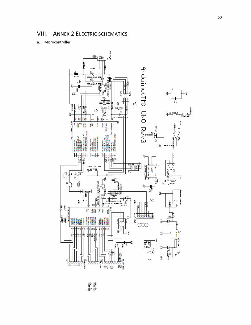
60
VIII. ANNEX 2 ELECTRIC SCHEMATICS a. Microcontroller
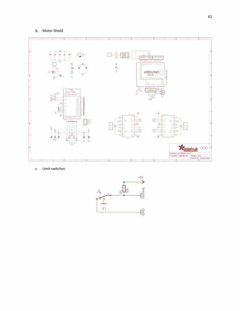
61
b. Motor Shield
c. Limit switches

62
IX. ANNEX 3 ASSEMBLE DRAWINGS
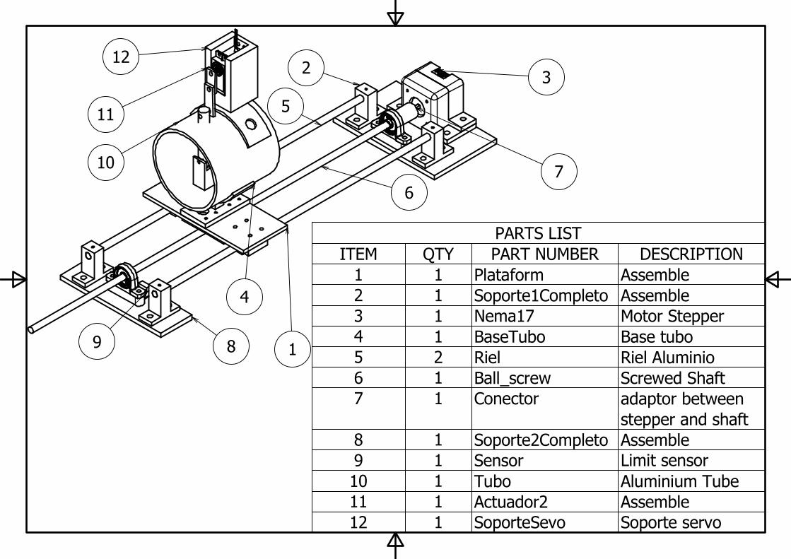
PARTS LIST
DESCRIPTIONPART NUMBERQTYITEM
AssemblePlataform11
AssembleSoporte1Completo12
Motor StepperNema1713
Base tuboBaseTubo14
Riel AluminioRiel25
Screwed ShaftBall_screw16
adaptor between
stepper and shaft
Conector17
AssembleSoporte2Completo18
Limit sensorSensor19
Aluminium TubeTubo110
AssembleActuador2111
Soporte servoSoporteSevo112
12
11
10
2
3
7
5
6
1
4
8
9
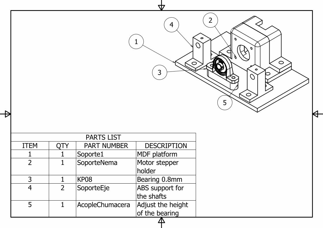
PARTS LIST
DESCRIPTIONPART NUMBERQTYITEM
MDF platformSoporte111
Motor stepper
holder
SoporteNema12
Bearing 0.8mmKP0813
ABS support for
the shafts
SoporteEje24
Adjust the height
of the bearing
AcopleChumacera15
1
4
3
2
5
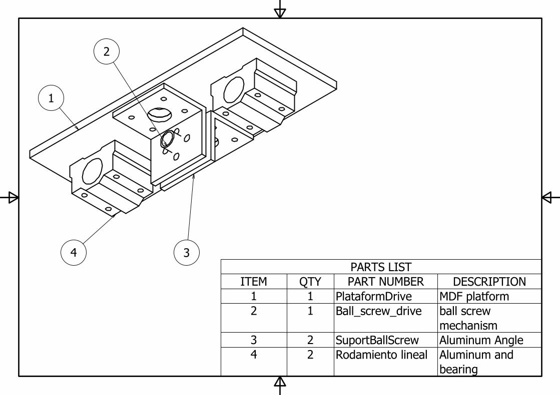
PARTS LIST
DESCRIPTIONPART NUMBERQTYITEM
MDF platformPlataformDrive11
ball screw
mechanism
Ball_screw_drive12
Aluminum AngleSuportBallScrew23
Aluminum and
bearing
Rodamiento lineal24
4
1
3
2

PARTS LIST
DESCRIPTIONPART NUMBERQTYITEM
MDF PlatformSoporte211
ABS support for
the shaft
SoporteEje22
ajust the height of
the bearing
AcopleChumacera13
BearingKP0814
2
4
3
1
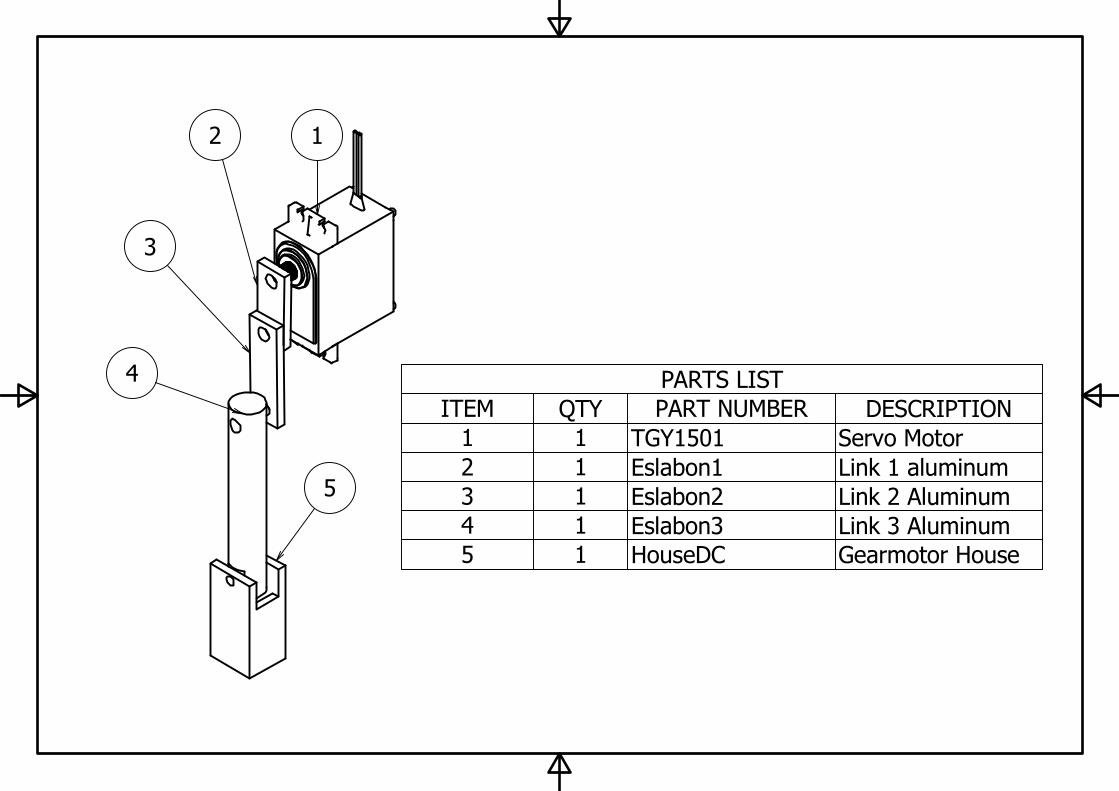
PARTS LIST
DESCRIPTIONPART NUMBERQTYITEM
Servo MotorTGY150111
Link 1 aluminumEslabon112
Link 2 AluminumEslabon213
Link 3 AluminumEslabon314
Gearmotor HouseHouseDC15
2 1
3
4
5