Design of Thermal Stabilizer and Data Acquisition System Using 89C51 Microcontroller and LabView
11
Design of Thermal Stabilizer and Data Acquisition System Using 89C51 Microcontroller and LabView NS Haider Ali ¿ , NS Hammad Shaikh ¿ , NS HassaanBaig ¿ *Department of Mechtronics Engineering, College of E&ME, NUST, Rawalpindi [email protected] [email protected] [email protected] Abstract: The objective of this project is to develop an efficient laptop thermal stabilizer using Data acquisition through LabView and control the fan speed using a PWM control by devising an algorithm by modeling heat flow using a physics simulator. Key words: Data acquisition, PWM control of motor, Thermal stabilizer. I. Introduction: Modern day computing systems, due to their complexity and high processing frequency, require an efficient cooling system. Certain PCs contain a lot of ICs, which require external as well as internal cooling systems as the processing slows down and the computer eventually stops working because of immense heating. Fan control in a laptop is very instrumental to its process since it ensures system cooling, mainly the ICs. The desired system is external to the laptop and acquires data using LabView GUI. Real-time data is read, processed and stored. A microcontroller based system can be connected to PC in a variety of ways: the industrial system adapter ISA or peripheral control interface PCI connector, the serial port, the parallel port, or the USB port. USB based data acquisition systems can be developed using USB controllers like ISP1181 connected to P89c51RD2 microcontroller [1], or using PICI6F877 microcontroller[2], or using T232/245BM USB interface chip to microcontroller[3]. An arduino microcontroller can also be employed to perform the desired data acquisition, as well as speed control of the fan. An arduino interfacing system is much more cost
Transcript of Design of Thermal Stabilizer and Data Acquisition System Using 89C51 Microcontroller and LabView
Design of Thermal Stabilizer and Data Acquisition System Using 89C51Microcontroller and LabView
NSHaiderAli¿, NSHammadShaikh¿, NSHassaanBaig¿
*Department of Mechtronics Engineering, College of E&ME, NUST,Rawalpindi
[email protected]@[email protected]
Abstract: The objective of this project is to develop an efficient laptop thermal stabilizer using Data acquisition through LabView and control the fan speed using a PWM control by devising an algorithm by modeling heat flow using a physics simulator.
Key words: Data acquisition, PWM control of motor, Thermal stabilizer.
I. Introduction: Modern day computing systems, due to their complexity and high processing frequency, require an efficient cooling system. Certain PCs contain a lot of ICs, which require external as well as internal cooling systems as the processing slows down and the computer eventually stops working because of immense heating. Fan control in a laptopis very instrumental to its process since it ensures system cooling, mainly the ICs. The desired system is external to
the laptop and acquires data using LabView GUI. Real-time data is read, processed and stored. A microcontroller based system can be connected to PC ina variety of ways: the industrial system adapter ISAor peripheral control interface PCI connector, the serial port, the parallel port, or the USB port. USB baseddata acquisition systems can be developed using USB controllers like ISP1181 connected to P89c51RD2 microcontroller [1], or using PICI6F877 microcontroller[2], orusing T232/245BM USB interfacechip to microcontroller[3]. An arduino microcontroller can alsobe employed to perform the desired data acquisition, as well as speed control of the fan. An arduino interfacing system is much more cost

effective compared to a PIC witha T232 interface. Arduino has anIntegrated Development Environment, IDE, which is user friendly, easy to understand andprogram in comparison to an IDE for a PIC microcontroller. Also,an arduino microcontroller provides a separate port to provide a PWM input, which is a necessity. Hence, an arduino interfacing system is a much better choice when developing anefficient system [4, 5]. For initial design purpose, the 89C51 microcontroller is used because of its availability and cheap cost. LabView software is integrated for monitoring and accessing the performance by acquiring and controlling the physical properties such as temperature of a device.
Temperature sensors are very common and widely used in industries. Multiple sensors areavailable with variable cost, sensing range, efficiency and sensitivity. An LM35 temperaturesensing IC is much more accuratecompared to an ordinary thermistor. Hence, it is much more efficient and cost effective [6].
Transient is the sudden change in some physical parameter of
the environment or the sudden rise in usage of the system CPU.This results in a change in temperature output in the form of transients. This effect, if not catered for, can be very harmful as it can burn the actuators and render the coolingsystem ineffective. This danger can be accounted for by increasing the duty cycle gradually by developing a smart algorithm. The fan speed is controlled using a PWM control. The duty cycle is dependent on temperature input coming from the sensor and the speed of the fan depends upon the duty cycle of the PWM. To smother the transient that arise as a resultof transients in the input, the duty cycle rises to the requiredvalue steadily.
The simulation softwares to be used are Proteus and COMSOL Multiphysics. Proteus is a powerful tool for designing of electronic systems and simulation. COMSOL Multiphysics software simulates physical phenomenon such as acoustic and thermal systems and their inter-relationships.

II. Methodology: A short layout of how the data is obtained, analyzed, processed and used to ultimately control the fan is described in ‘Fig. 1’. A sensor picks up a temperature value andtransfers it to the microcontroller. This value is monitored at the LCD. A smart algorithm designed within the microcontroller, operates the motor at some RPM to control thefan.
Fig. 1 – Project Look-over
Another flow chart, shown in ‘Fig. 2’, displays the basic logic of how the fan is controlled. There is a temperature checkpoint labeledTset. For:
T>Tset, the fan turns on, otherwise it remains off.
Fig. 2 – Fan Control
The end to which we are devisingthis product is to conserve energy and to boost performance in case of excessive processing as a consequence of running someheavy application.
‘Fig. 3’ and ‘Fig. 4’ show data on the power consumption of the hard drive and the motherboard of a Dell P4 laptop [7].
Fig. 3 – Hard Drive PowerConsumption Chart
Fig. 4 – Motherboard PowerConsumption Chart
On average, an individual uses alaptop for a minimum of four hours in a day. Using the above data from the charts in ‘Fig. 3’and ‘Fig. 4’, we can calculate

the energy loss in terms of money per annum as follows:
PowerConsumption=151W
Usage(¿hours)=4
kWhused=0.604
CostperDay@ 11centskWh
=$0.06644
CostperYear=$24.2506
This data is for the energy lostin one laptop’s motherboard.
Graphs show the variation in internal temperature and the busand rated bus speed of the CPU, obtained using the software “Speecy”, before and after turning on the game ‘Dota 2’.
Temperature: Before turning the game on, the graph remains near or at the 43°C mark without muchvariation, which is shown in ‘Fig. 5’, while just after turning on the game, it starts to rise almost instantly and varies around the 55°C mark, as in ‘Fig. 6’.
Before:
Fig. 5 – Temperature VariationGraph before Running an
Application
After:
Fig. 6 – Temperature VariationGraph after Running an
Application
Bus and Rated Bus Speed: The fluctuations in the frequency ofboth the bus and rated bus speed

rise almost instantly when the game is on compared to when it is not running. If the game keeps running, the speed remainsquite high at all times while the temperature also rises to a high value of 62°C, displayed through ‘Fig. 7’ to ‘Fig. 11’.
Before:
Fig. 7 – Bus Speed beforeRunning Application
Fig. 8 – Rated Bus Speed beforeRunning Application
After:
Fig. 9 – Bus Speed after RunningApplication
Fig. 10 – Rated Bus Speed afterRunning Application
After a long time:

Fig. 11 – Speed after LongDuration
All these graphs indicate a sudden rise in temperature and the processing speed when a heavy application is in use.
In order to make the device, we need to find a relationship between temperature reduction ofthe CPU (T) and duty cycle of the PWM of the motor (d) “d(T)”. But no such relationship exists.So, in order to find this relationship, we find a relationship between duty cycle of the PWM and RPM (ω), “d¿ω)”, the RPM (ω) and volumetric flow rate of air (V) “ω(V)” and volumetric flow rate and temperature “V(T)” => d(ω(V(T))).For better understanding, a small layout is described in ‘Fig. 12’.
Fig. 12 – Cyclic Process of Fan Functioning
At a specific temperature, the fan CFM required to bring the laptop down to the optimum temperature is specific and the excessive CFM provided by the ordinary fan is wasted, hence, wasting a lot of energy. To calculate the exact value of CFMrequired, five experiments were designed:
1. Exp 1: Relationship betweenPWM and RPM using Tachometer.
2. Exp 2: Calculating the CFM of a fan using an object ofknown volume.
3. Exp 3: Relationship betweenRPM and CFM using a known heating device.
4. Exp 4: Sensor output with respect to temperature at acertain PWM.
5. Exp 5: Calculating the relationship between CFM and Temperature.
Simulation in COMSOL Multiphysics:
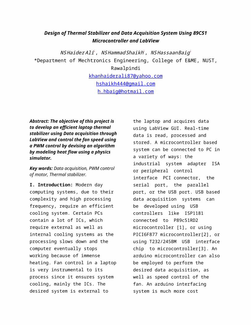
COMSOL Multiphysics an environment for simulating some physical phenomenon. The requirement of the system is to know what temperature is sensed at a particular distance from the laptop heat sink by the thermal sensor. This is done using the Heat Transfer (HT) study of the aforementioned software. The following design serves the purpose:
Fig. 13 – COMSOL Simulation ofHeat Dissipation from Laptop
The sensing element is located at a distance of 0.015m from thelaptop heat sink. The white portion represents a hotter region (represented by the scale) and the heat dissipates slowly as it gets nearer to the sensing element (Fig.s 13 and 14).
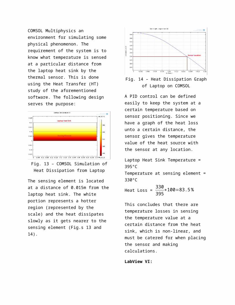
Fig. 14 – Heat Dissipation Graphof Laptop on COMSOL
A PID control can be defined easily to keep the system at a certain temperature based on sensor positioning. Since we have a graph of the heat loss unto a certain distance, the sensor gives the temperature value of the heat source with the sensor at any location.
Laptop Heat Sink Temperature = 395°CTemperature at sensing element =330°C
Heat Loss = 330395∗100=83.5%
This concludes that there are temperature losses in sensing the temperature value at a certain distance from the heat sink, which is non-linear, and must be catered for when placingthe sensor and making calculations.
LabView VI:

A LabView VI shows the systematic working of how the system works:
Fig. 15 – LabView VI for PWMGeneration
The sensing element takes a temperature value and creates a PWM provided at the fan. The PWMduty cycle depends on the temperature value at the thermalsensor. The duty cycle rises with an increase in temperature.The Boolean outputs show the ON and OFF time for one complete wave of the PWM (Fig.s 15 and 16).
Fig. 16 – LabView VI InputControl and Output Display
Proteus Simulation:
A simulation of the hardware circuit on the Proteus 8.0 Professional software provides results for different temperature values at the LM35 thermistor in Fig. 17.
Fig. 17 – Proteus Simulation ofPWM Generation and Motor Controlthrough 89C51 Microcontroller
An ADC0801 converts the analog voltage output of the LM35 into an 8-bit digital output given toPort 2 of the 89C51 microcontroller, which in turn produces a PWM at the Port pin P1^0. This PWM is integrated in a summing amplifier and providedto the fan motor. The circuit specifications are:
MinimumLM35output=20mVMaximumLM35output=80mV
Microcontroller Coding:
The program that converts the ADC0801 output into a PWM to be

given to the fan is burnt into the 89C51 microcontroller:
#include<reg51.h>sbit cs=P3^3 ;sbit wr=P3^1 ; sbit rd=P3^0 ; sbit intr=P3^2;sbit out=P1^0 ;unsigned int b ;unsigned int a ;unsigned int c ;unsigned int h;void Delay(unsigned int) ;main(){while(1){cs=0;rd=0;cs=1;Delay(2);cs=0;wr=1;Delay(2);wr=0;a=P2;a=a*100;b=a/255;c=100-b;for(h=0;h<c;h++){out=0;Delay(1);}for(h=0;h<b;h++){out=1;Delay(1);}}}
void Delay(unsigned int d){unsigned int i,j;for(i=0;i<c;i++)for(j=0;j<10;j++);}
This code takes into account thefunctionality of the ADC0801 andconverts the LM35 output accordingly.
III. Results: To gauge the accuracy of the system, a comparison between the simulation and practical structure was made and the following results were obtained:
Picture 1 – Fan RPM at Room Temperature
RPM=1669
Heat Source:
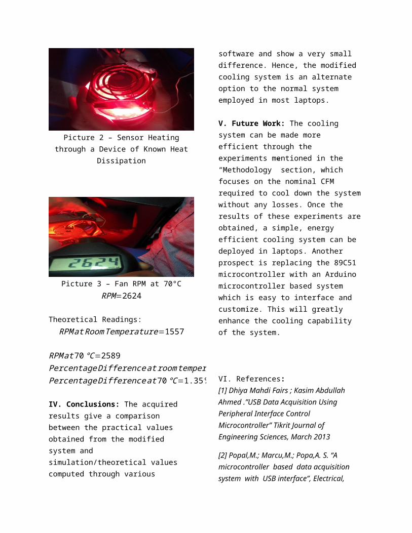
Picture 2 – Sensor Heatingthrough a Device of Known Heat
Dissipation
Picture 3 – Fan RPM at 70°CRPM=2624
Theoretical Readings:RPMatRoomTemperature=1557
RPMat70℃=2589 PercentageDifferenceatroomtemperature=7.19%PercentageDifferenceat70℃=1.35%
IV. Conclusions: The acquired results give a comparison between the practical values obtained from the modified system and simulation/theoretical values computed through various
software and show a very small difference. Hence, the modified cooling system is an alternate option to the normal system employed in most laptops.
V. Future Work: The cooling system can be made more efficient through the experiments mentioned in the “Methodology” section, which focuses on the nominal CFM required to cool down the systemwithout any losses. Once the results of these experiments areobtained, a simple, energy efficient cooling system can be deployed in laptops. Another prospect is replacing the 89C51 microcontroller with an Arduino microcontroller based system which is easy to interface and customize. This will greatly enhance the cooling capability of the system.
VI. References: [1] Dhiya Mahdi Fairs ; Kasim Abdullah Ahmed .”USB Data Acquisition Using Peripheral Interface Control Microcontroller” Tikrit Journal of Engineering Sciences, March 2013
[2] Popal,M.; Marcu,M.; Popa,A. S. “A microcontroller based data acquisition system with USB interface”, Electrical,

Electronic and Computer Engineering,2004.ICEEC
[3] Axelson, J., “USB Complete: Everything You Need to Develop Custom USB Peripherals”, Lakeview Research, 2001, ISBN 09655081958
[4] Ziad Salem, Ismail Al Kamal, Alaa Al, Bashar “A Novel Design of an Industrial Data Acquisition System” --0-7803-9521-2/06 IEEE 2006.
[5] S. Thanee S. Somkuarnpanit and K. Saetang -FPGA-Based Multi Protocol Data Acquisition System with High Speed USB Interface. ISSN: 2078-0958 IMECS2010.
[6] Nishantkumar D. Gajipara; Prashant L. Ahire “Design of SCADA for Real Time System with LabVIEW and Microcontroller” International Journal of Innovative Researchin Advanced Engineering (IJIRAE) ISSN: 2349-2163Volume 1 Issue 7 (August 2014)
[7] Heat Dissipation in a Computer Amollo T.A, Kirui M.S.K, Golicha H.S.A, KemeiS.K, Nyakan P.O Faculty of Science, Department of Physics, Egerton University, P.O BOX 536-20115, Egerton , Njoro, Kenya.