DESIGN OF PILOT-SYMBOL ASSISTED POWER DELAY PROFILE ESTIMATION FOR MIMO-OFDM SYSTEMS
11
International Journal of Electrical Engineering and Technology (IJEET), ISSN 0976 – 6545(Print), ISSN 0976 – 6553(Online) Volume 4, Issue 5, September – October (2013), © IAEME 36 DESIGN OF PILOT-SYMBOL ASSISTED POWER DELAY PROFILE ESTIMATION FOR MIMO-OFDM SYSTEMS PRATHIMA BOPPANA Mtech( Wireless and Mobile Communication), Vaagdevi College of Engineering, Bollikunta, Warangal, Andhra Pradesh, India M. SHIVA PRASAD Assistant Professor, ECE Department, Vaagdevi College of Engineering, Bollikunta, Warangal, Andhara Pradesh, India ABSTRACT This work proposes a power delay profile (PDP) estimation technique for linear minimum mean square error (LMMSE) channel estimator of multiple-input multiple-output orthogonal frequency division multiplexing (MIMO-OFDM) systems. For practical applications, only the pilot symbols of all transmit antenna ports are used in estimating the PDP. The distortions caused by null subcarriers and an insufficient number of samples for PDP estimation are also considered. This technique effectively reduces the distortions for accurate PDP estimation. Simulation results show that the performance of LMMSE channel estimation using the proposed PDP estimate approaches that of Wiener filtering due to the mitigation of distortion effects. Index Terms: Channel estimation, power delay profile, MIMO, OFDM, 3GPP-LTE. INTRODUCTION MULTIPLE-INPUT multiple-output orthogonal frequency division multiplexing (MIMO- FDM) is one of the most promising techniques for wireless communication systems, including the 3rd Generation Partnership Project Long Term Evolution (3GPP LTE) and IEEE 802.16 (WiMAX). MIMO-OFDM provides a considerable performance gain over broadband single-antenna systems by obtaining the spatial diversity or multiplexing gain. Most receiver techniques of MIMO-OFDM systems are designed with the assumption that channel state information (CSI) is available, in order to achieve the maximum diversity or multiplexing gain. The performance gain depends heavily on accurate channel estimation, which is crucial for the MIMO-OFDM systems. INTERNATIONAL JOURNAL OF ELECTRICAL ENGINEERING & TECHNOLOGY (IJEET) ISSN 0976 – 6545(Print) ISSN 0976 – 6553(Online) Volume 4, Issue 5, September – October (2013), pp. 36-46 © IAEME: www.iaeme.com/ijeet.asp Journal Impact Factor (2013): 5.5028 (Calculated by GISI) www.jifactor.com IJEET © I A E M E
Transcript of DESIGN OF PILOT-SYMBOL ASSISTED POWER DELAY PROFILE ESTIMATION FOR MIMO-OFDM SYSTEMS
International Journal of Electrical Engineering and Technology (IJEET), ISSN 0976 – 6545(Print),
ISSN 0976 – 6553(Online) Volume 4, Issue 5, September – October (2013), © IAEME
36
DESIGN OF PILOT-SYMBOL ASSISTED POWER DELAY PROFILE
ESTIMATION FOR MIMO-OFDM SYSTEMS
PRATHIMA BOPPANA Mtech( Wireless and Mobile Communication),
Vaagdevi College of Engineering, Bollikunta, Warangal, Andhra Pradesh, India
M. SHIVA PRASAD Assistant Professor, ECE Department,
Vaagdevi College of Engineering, Bollikunta, Warangal, Andhara Pradesh, India
ABSTRACT
This work proposes a power delay profile (PDP) estimation technique for linear minimum
mean square error (LMMSE) channel estimator of multiple-input multiple-output orthogonal
frequency division multiplexing (MIMO-OFDM) systems. For practical applications, only the pilot
symbols of all transmit antenna ports are used in estimating the PDP. The distortions caused by null
subcarriers and an insufficient number of samples for PDP estimation are also considered. This
technique effectively reduces the distortions for accurate PDP estimation. Simulation results show
that the performance of LMMSE channel estimation using the proposed PDP estimate approaches
that of Wiener filtering due to the mitigation of distortion effects.
Index Terms: Channel estimation, power delay profile, MIMO, OFDM, 3GPP-LTE.
INTRODUCTION
MULTIPLE-INPUT multiple-output orthogonal frequency division multiplexing (MIMO-
FDM) is one of the most promising techniques for wireless communication systems, including the
3rd Generation Partnership Project Long Term Evolution (3GPP LTE) and IEEE 802.16 (WiMAX).
MIMO-OFDM provides a considerable performance gain over broadband single-antenna systems by
obtaining the spatial diversity or multiplexing gain. Most receiver techniques of MIMO-OFDM
systems are designed with the assumption that channel state information (CSI) is available, in order
to achieve the maximum diversity or multiplexing gain. The performance gain depends heavily on
accurate channel estimation, which is crucial for the MIMO-OFDM systems.
INTERNATIONAL JOURNAL OF ELECTRICAL ENGINEERING &
TECHNOLOGY (IJEET)
ISSN 0976 – 6545(Print) ISSN 0976 – 6553(Online) Volume 4, Issue 5, September – October (2013), pp. 36-46 © IAEME: www.iaeme.com/ijeet.asp Journal Impact Factor (2013): 5.5028 (Calculated by GISI) www.jifactor.com
IJEET
© I A E M E
International Journal of Electrical Engineering and Technology (IJEET), ISSN 0976 – 6545(Print),
ISSN 0976 – 6553(Online) Volume 4, Issue 5, September – October (2013), © IAEME
37
The pilot-aided channel estimation, based on the linear minimum mean square error
(LMMSE) technique, is optimum in the sense of minimizing mean square error (MSE) when the
receiver knows the channel statistics .To obtain the frequency domain channel statistics at the
receiver, power delay profile (PDP) estimation schemes have been proposed . These schemes are
based on the maximum likelihood (ML) estimation by taking advantage of the cyclic prefix (CP)
segment of OFDM symbols. However, the ML PDP estimators require very high computational
complexity for obtaining an accurate PDP.
Another approach for improving the performance of LMMSE channel estimation employs an
approximated PDP (i.e., uniform or exponential model) with the estimation of second-order channel
statistics, which are mean delay and root-mean-square (RMS) delay spread. The channel delay
parameters are estimated using pilots with low computational complexity. Therefore, the LMMSE
channel estimator with the approximated PDP is appropriate for practical applications such as a
WiMAX system. However, the performance degradation is caused by both the correlation mismatch
and the estimation error of delay parameters.
To reduce the mismatch in the frequency domain, we propose a PDP estimation technique for
the LMMSE channel estimator of MIMO-OFDM systems. For practical applications, the proposed
technique uses only the pilot symbols of all transmit antenna ports to estimate the PDP with low
computational complexity. In addition, the proposed technique effectively mitigates the distortion
effects, incurred by null subcarriers and an insufficient number of estimated channel impulse
response (CIR) samples. Simulation results show that the performance of LMMSE channel
estimation with the proposed PDP estimate approaches that of Wiener filtering.
SYSTEM MODEL AND DEVELOPMENT
The system under consideration is a MIMO-OFDM system with P transmit and Q receive
antennas, and K total subcarriers. Suppose that the MIMO-OFDM system transmits Kd subcarriers at
the central spectrum assigned for data and pilots with K-Kd virtual subcarriers, in order to control
interferences with other systems. The CIRs corresponding to different transmit and receive antennas
in MIMO systems usually have the same PDP .
Let Cp[kp,np] be the pilot subcarrier for the pth
transmit antenna at the npth OFDM symbol,
which is a QPSK modulated signal from known sequences between the transmitter and receiver. We
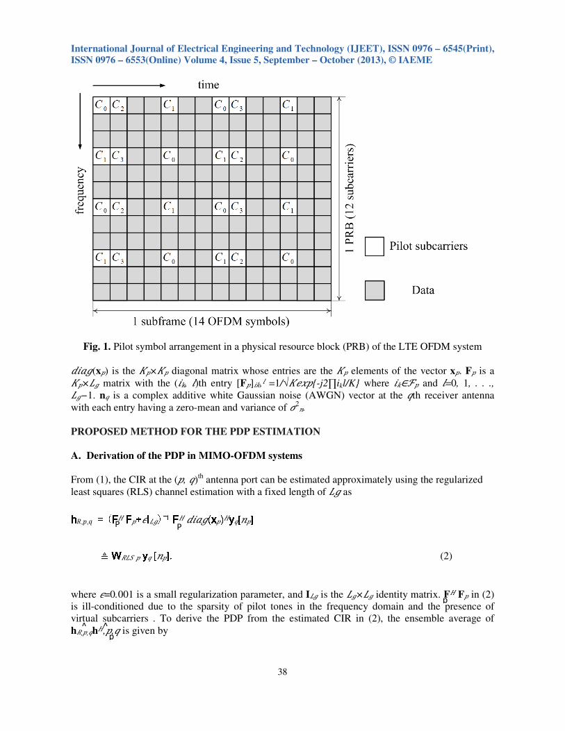
assume that the pilot subcarriers are distributed over a time and frequency grid as in Fig. 1, to
preserve the orthogonality of pilots among different transmit antennas. ��∈ℱ� and �∈�� represent
the index sets for the pilot subcarriers of the �th antenna port in the frequency and time domains,
respectively. At the �th OFDM symbol, the number of pilot subcarriers is defined as ��=∣ℱ�∣. The
pilot inserted OFDM symbol is transmitted over the wireless channel after performing an inverse fast
Fourier transform (IFFT) and adding a CP. It is assumed that the length of CP, ��, is longer than the
channel maximum delay, ��ℎ, making the channel matrix circulant (��慜ℎ ≤ ��).
At the receiver, after perfect synchronization, the removal of CP, and FFT operation, the
received pilot symbol for the �th receive antenna can be represented as
y�[�] = ����(x�)Fph�,� + n�, (1)
where h�,�=[ℎ�,�[�, 0], ℎ�,�[�, 1], . . . , ℎ�,�[�, ��ℎ], 0, . . . , 0]� is an ��×1 CIR vector at
the �th transmit antenna and �th receive antenna. (⋅)� and (⋅)� represent the transpose operation, and
the transpose and conjugate operation of a vector or matrix, respectively. x� = [��[�1, �],
��[�2, �], . . . , ��[���, �]]� denotes a pilot vector at the � th OFDM symbol for ��∈ℱ� and
�=1, 2, . . .,��.
International Journal of Electrical Engineering and Technology (IJEET), ISSN 0976 – 6545(Print),
ISSN 0976 – 6553(Online) Volume 4, Issue 5, September – October (2013), © IAEME
38
P P
p
p
^ ^
Fig. 1. Pilot symbol arrangement in a physical resource block (PRB) of the LTE OFDM system
����(x�) is the ���� diagonal matrix whose entries are the �� elements of the vector x�. F� is a
��×�� matrix with the (�k, �)th entry [F�]��,� =1/√�� �{-j2∏ikl/K} where ��∈ℱ� and �=0, 1, . . .,
��−1. n� is a complex additive white Gaussian noise (AWGN) vector at the �th receiver antenna
with each entry having a zero-mean and variance of !2.
PROPOSED METHOD FOR THE PDP ESTIMATION
A. Derivation of the PDP in MIMO-OFDM systems
From (1), the CIR at the (�, �)th
antenna port can be estimated approximately using the regularized
least squares (RLS) channel estimation with a fixed length of �� as
hhhh",�,� = (FFFF� FFFF�+#IIII��)−1 FFFF� ����(xxxx�)�yyyy�[�] ≜ WWWW"�%,� yyyy� [�], (2)
where #=0.001 is a small regularization parameter, and I�� is the ���� identity matrix. F� F� in (2)
is ill-conditioned due to the sparsity of pilot tones in the frequency domain and the presence of
virtual subcarriers . To derive the PDP from the estimated CIR in (2), the ensemble average of
h",�,�h�,�,� is given by

International Journal of Electrical Engineering and Technology (IJEET), ISSN 0976 – 6545(Print),
ISSN 0976 – 6553(Online) Volume 4, Issue 5, September – October (2013), © IAEME
39
p p
p
R,p,q
P,q ˜
P,q
H
RLS,p
H H
˜
˜
(3)
where Rℎℎ=&{h�,�hH,p,�} and W=(F� F� +#I�� )
−1F� F�.Note that the diagonal elements of the
channel covariance matrix, Rℎℎ, represent the PDP of multipath channel within the length of ��, and
all off-diagonal elements are zeros. Hence, the covariance matrix can be expressed as Rℎℎ=����
(pℎ), where pℎ=[�0, �1, . . . , ���ℎ, 0, . . . , 0]� and ��=&{∣ℎ�,�[�, �]∣2}. Unfortunately, Rℎℎ is
distorted by W,which is an ill-conditioned matrix due to the presence of F� F�. Thus, instead of
calculating W−1
, we investigate the method for eliminating the spectral leakage of W.
The covariance matrix of the estimated CIR is defined as Rhh=WRhhWH which can be
expressed as
Rhh = (plul)WH, (4)
Where ul is a unit vector with the lth entry being one and otherwise zeros.Let ph and tl be the
Lg ×1 vectors defined as ph=Dg(Rhh) and tl=D(Wdiag(ul)WH),respectively where Dg(A) is the
column vector containing all diagonal elements of A.Then, the relation in (4) is simplified as
Ph = p0t0+ p1tl +…..+PLg-1tLg-1≜TpTpTpTph, (5)
Where T=[t0,t1,….tLg-1] is defined as a distortion matrix by W. It is noted that the distortion
matrix is a strictly diagonally dominant matrix, satisfying ∣[TTTT]��∣>Σ+∕=� ∣[TTTT]�+ ∣ for all I,j, since the
non-diagonal elements of T are composed of the leakage powers of ui for all i. From the
Gershgorin circle theorem, a strictly diagonally dominant matrix is non-singular. In
addition, the distortion matrix is a well-conditioned matrix. Hence ,the distortion of WWWW can be
eliminated as (6)
Where is defined as the received sample
vector for estimating PDP at the (p,q)th antenna port on the npth OFDM symbol, and
W =
B. PDP Estimation in Practical MIMO-OFDM Systems
The received sample vector in (6) can be expressed as
gp,q[np]=Dg(hp,qhH ) + np,q + ep,q, (7)
where np,q = T-1
Dg(WRLS,pnqnqWH
) and ep,q = 2Re T-1
Dg(WRLS,pnqnqWRLS,p)
Here,Re a denotes the real part of a.We assume that np,q is an effective noise by AWGN. Then
International Journal of Electrical Engineering and Technology (IJEET), ISSN 0976 – 6545(Print),
ISSN 0976 – 6553(Online) Volume 4, Issue 5, September – October (2013), © IAEME
40
z init
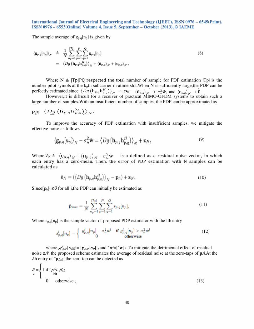
The sample average of gp,q[np] is given by
(8)
Where N ≜ |Tp|PQ respected the total number of sample for PDP estimation |Tp| is the
number pilot symols at the kpth subcarrier in atime slot.When N is sufficiently large,the PDP can be
perfectly estimated.since
However,it is difficult for a receiver of practical MIMO-OFDM systems to obtain such a
large number of samples.With an insufficient number of samples, the PDP can be approximated as
Ph≈
To improve the accuracy of PDP extimation with insufficient samples, we mitigate the
effective noise as follows
(9)
Where ZN ≜ is a defined as a residual noise vector, in which
each entry has a zero-mean. Then, the error of PDP estimation with N samples can be
calculated as
(10)
Since[ph]I ≥0 for all i,the PDP can initially be estimated as
(11)
Where sp,q[np] is the sample vector of proposed PDP estimator with the lth entry
(12)
where ���,�[��]= [g�,�[�]]� and ˜N�=[˜w]�. To mitigate the detrimental effect of residual
noise zO, the proposed scheme estimates the average of residual noise at the zero-taps of pℎ.At the
�th entry of ˆp��P, the zero-tap can be detected as
P� = 1 if ˆ��< QPℎ,
0 otherwise , (13)

International Journal of Electrical Engineering and Technology (IJEET), ISSN 0976 – 6545(Print),
ISSN 0976 – 6553(Online) Volume 4, Issue 5, September – October (2013), © IAEME
41
p
n
p n
p n
p p p p
^
z
^ ^ ^ ^ ^
^
^
n p
whereQPℎ = plinit is defined as a threshold value for the zero-tap detection. Then, the average of
residual noise at the zero-taps can be estimated as
nR,avg = linit
tlz’ (14)
where OR=l represents the total number of detected zero-taps. With the mitigation of residual
noise, the �th tap of the PDP estimate, pℎ, can be expressed as
�l = ����P − ",�S� if ��
��P > ",�S�
0 otherwise . (15)
Then, the estimated PDP in (15) can be used to obtain the frequency-domain channel correlation in
the LMMSE channel estimator.
PERFORMANCE AND COMPLEXITY ANALYSIS
The LMMSE channel estimator with the imperfect PDP in (15) is given by
(16)
where F� is the �d× �g matrix obtained by taking the first �� columns of the DFT matrix. pℎ = pℎ
+ e��� is expressed as the estimated PDP, where the �th element of e��� is defined as
(17)
From the matrix inversion lemma, (F�T�(ˆpℎ)F�+ !2I�� )
−1 in (22) is converted as
(18)
where A A A A ≜ (FFFF�T� (ppppℎ)FFFFHHHH + !2I��) and B B B B ≜T�(eeee���) (I��+F
HA−1FFFF�T�(eeee���))−1. Then, the
coefficient matrix for LMMSE channel estimation with ˆppppℎ can be rewritten as
WWWWU,� =WWWWV�P,� +WWWW�WW,�, (19)
where WV�P,� ≜ F�T�(pℎ)F� (F�T�(pℎ)F�+ !2I��)
−1 is the coefficient matrix for Wiener filtering,
and W�WW,� is given by W�WW,� = −F�T�(pℎ)F�A
−1F�BF�A
−1 + F�T�(e���)F�(F�T�(ˆpℎ)F�+ !
2I)
−1 (20)
International Journal of Electrical Engineering and Technology (IJEET), ISSN 0976 – 6545(Print),
ISSN 0976 – 6553(Online) Volume 4, Issue 5, September – October (2013), © IAEME
42
g g
^ ^
n p f,p’
The error covariance matrix of LMMSE channel estimation with the imperfect PDP can be obtained
as
E� = & (F�h�,�−WU,�h�%,�,�)(F�h�,�−WU,�h�%,�,�)�
= (F� −WU,�F�)T�(pℎ) (F� −WU,�F�)� + !2WU,�F�F�W� (21)
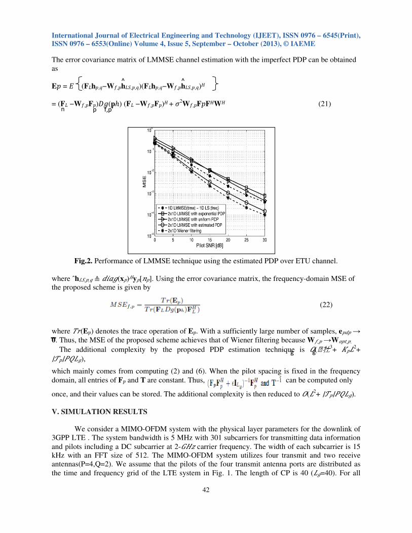
Fig.2. Performance of LMMSE technique using the estimated PDP over ETU channel.
where ˆh�%,�,� ≜ ����(x�)�y�[�]. Using the error covariance matrix, the frequency-domain MSE of
the proposed scheme is given by
(22)
where �W(E�) denotes the trace operation of E�. With a sufficiently large number of samples, e��� →
0. Thus, the MSE of the proposed scheme achieves that of Wiener filtering because WU,� →WV�P,�.
The additional complexity by the proposed PDP estimation technique is X(�牡3+ ���2
+
∣�p∣YZ��),
which mainly comes from computing (2) and (6). When the pilot spacing is fixed in the frequency
domain, all entries of F� and T are constant. Thus, can be computed only
once, and their values can be stored. The additional complexity is then reduced to X(�2+ ∣��∣YZ��).
V. SIMULATION RESULTS
We consider a MIMO-OFDM system with the physical layer parameters for the downlink of
3GPP LTE . The system bandwidth is 5 MHz with 301 subcarriers for transmitting data information
and pilots including a DC subcarrier at 2-[�R carrier frequency. The width of each subcarrier is 15
kHz with an FFT size of 512. The MIMO-OFDM system utilizes four transmit and two receive
antennas(P=4,Q=2). We assume that the pilots of the four transmit antenna ports are distributed as
the time and frequency grid of the LTE system in Fig. 1. The length of CP is 40 (��=40). For all
International Journal of Electrical Engineering and Technology (IJEET), ISSN 0976 – 6545(Print),
ISSN 0976 – 6553(Online) Volume 4, Issue 5, September – October (2013), © IAEME
43
simulations, the channel estimator is based on a cascaded 2×1D LMMSE technique during 14
OFDM symbols (∣�1∣ = ∣�2∣ = 2, ∣�3∣ = ∣�4∣ = 1), as shown in Fig. 1, where the filtering in frequency
domain is followed by the filtering in time domain over slowly fading channels with the Doppler
frequency of 5 Hz.
Figure 2 shows the MSE performance of the 2×1D LMMSE technique using the estimated
PDP. All underlying links are modeled as extended typical urban (ETU) channels . The performance
of the 2×1D Wiener filter with exact PDP is included as a lower bound. For performance
comparisons, we plot the performance of frequency domain regularized LS channel
estimation in which the PDP information is not required. The performance of the 2×1D LMMSE
technique using the approximated PDP, which is uniform or exponential model with the channel
delay parameter estimation in [11], is also plotted. Note that the LMMSE technique using the
estimated PDP outperforms the conventional methods, since the correlation mismatch is reduced by
the proposed PDP.
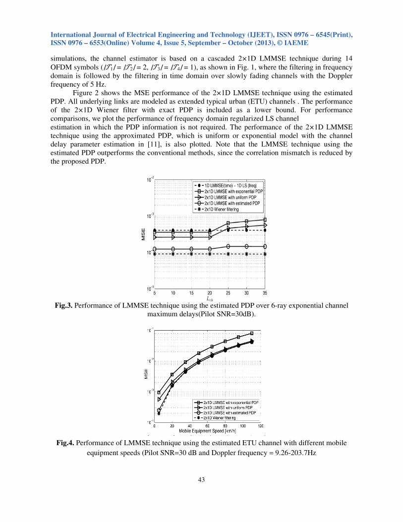
Fig.3. Performance of LMMSE technique using the estimated PDP over 6-ray exponential channel
maximum delays(Pilot SNR=30dB).
Fig.4. Performance of LMMSE technique using the estimated ETU channel with different mobile
equipment speeds (Pilot SNR=30 dB and Doppler frequency = 9.26-203.7Hz
International Journal of Electrical Engineering and Technology (IJEET), ISSN 0976 – 6545(Print),
ISSN 0976 – 6553(Online) Volume 4, Issue 5, September – October (2013), © IAEME
44
5
estimation. We also observe from Fig. 3 that the proposed method has a performance loss within
only a 2.4-dB gap,compared with 2×1D Wiener filtering.
In Fig. 3, we investigate the MSE performance of the proposed scheme over the
exponentially power decaying six-path Rayleigh fading channel model, where the channel maximum
delay, ��ℎ, is variable. The PDP of the channel model is defined as for �=0,∆\, . . . , 5∆\ and ∆\=��ℎ . Here, is the normalization factor (%ℎ=Σ� �−�/\W]^)
.
The performance of the proposed scheme is better than that of the conventional methods, and
approaches that of Wiener filtering in various channel environments.
Figure 4 shows the MSE performance of the 2×1D LMMSE technique using the estimated
PDP for different mobile equipment speeds at 30-�_ SNR. All underlying links are modeled as ETU
channels. In Fig. 4, it can be seen that the MSE of LMMSE technique using the estimated PDP
achieves that of Wiener filtering even at high Doppler frequencies.
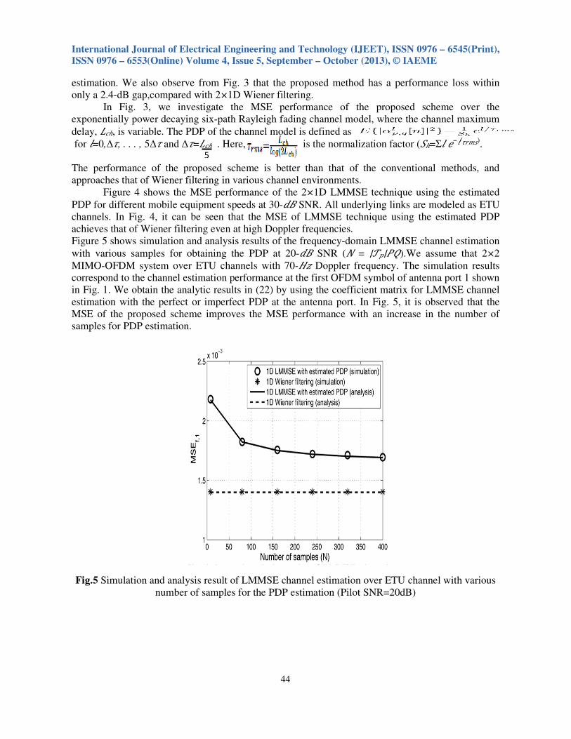
Figure 5 shows simulation and analysis results of the frequency-domain LMMSE channel estimation
with various samples for obtaining the PDP at 20-�_ SNR (O = ∣��∣YZ).We assume that 2×2
MIMO-OFDM system over ETU channels with 70-�R Doppler frequency. The simulation results
correspond to the channel estimation performance at the first OFDM symbol of antenna port 1 shown
in Fig. 1. We obtain the analytic results in (22) by using the coefficient matrix for LMMSE channel
estimation with the perfect or imperfect PDP at the antenna port. In Fig. 5, it is observed that the
MSE of the proposed scheme improves the MSE performance with an increase in the number of
samples for PDP estimation.
Fig.5 Simulation and analysis result of LMMSE channel estimation over ETU channel with various
number of samples for the PDP estimation (Pilot SNR=20dB)

International Journal of Electrical Engineering and Technology (IJEET), ISSN 0976 – 6545(Print),
ISSN 0976 – 6553(Online) Volume 4, Issue 5, September – October (2013), © IAEME
45
VI. CONCLUSIONS
We proposed a PDP estimation technique for the LMMSE channel estimator in MIMO-
OFDM systems. The CIR estimates at each path of the MIMO channels were used to obtain the PDP.
For accurate PDP estimation, we considered the spectral leakage effect from virtual subcarriers, and
the residual noise caused by the insufficient number of estimated CIR samples. The proposed
technique effectively mitigates both the spectrum leakage and residual noise. Simulation results
show that the performance of LMMSE channel estimation using the proposed PDP estimate
approaches that of Wiener filtering.
REFERENCES
[1] D. Tomecki, S. Stanczak, and M. Kaliszan, “Joint optimization of transmit and receive
beamformers in a multicast MIMO system with power control,” in Proc. IEEE Wireless
Communications and Networking Conference (WCNC), Budapest, Hungary, April, 5–8
2009.
[2] H.V.Kumaraswamy, "Implementation of Variable step size Griffiths' algorithm for Adaptive
Beam forming", in the IEEE- International symposium on Microwaves-2008(ISM-08), in
ISM- 08 Bangalore, ISM-08 Pages 91-95.
[3] N. Jindal and Z.-Q. Luo, “Capacity limits of multiple antenna multicast," Information
Theory, 2006 IEEE International Symposium on, pp. 1841 –1845, July 2006.
[4] N. Sidiropoulos, T. Davidson, and Z.-Q. Luo, “Transmit Beamforming for physical-layer
multicasting,” IEEE Trans. Signal Processing, vol. 54,no. 6, pp. 2239–2251, June 2006.
[5] E. Matskani, N. Sidiropoulos, Z.-Q. Luo, and L. Tassels, “Joint multicast Beamforming and
admission control,” in Computational Advances in Multi-Sensor Adaptive Processing, 2007.
CAMPSAP 2007. 2nd IEEE International Workshop, pp. 189 –192, December 2007,
[6] Lozano, “Long-term transmit Beamforming for wireless multicasting,” in Proceedings of
IEEE Int. Conf. on Acoustics, Speech and Signal Processing (ICASSP), vol. 3, pp. III– 417 –
III–420, April 2007.
[7] P. K. Gopala and H. E. Gamal, “Opportunistic multicasting,” in Signals, Systems and
Computers, 2004. Conference Record of the Thirty-Eighth Asilomar Conference on, vol. 1,
pp. 845 – 849 Vol.1, Nov. 2004.
[8] H.V.Kumaraswamy, "Comparative analysis of LMS, RLS and other Beam forming methods
in smart antenna", in the International conference on computer Communication and Control,
Dept. of E & C RVCE Bangalore, 21st – 23rd Nov 2007, Comm-11 244- 248.
[9] M. Luby, “LT codes,” in FOCS ’02: Proceedings of the 43rd Symposium on Foundations of
Computer Science. Washington, DC, USA: IEEE Computer Society, p. 271, 2002.
[10] Shokrollahi, “Raptor codes,” in IEEE Transactions on Information Theory, pp. 2551–2567,
2006.
[11] H.V.Kumaraswamy, "A New TURBO LMS Beamforming for Mobile Communication",
International Journal Computer Applications, 10th December 2010.
[12] Huy Hoang Pham Taniguchi, T. Karasawa, Y. “MIMO Beamforming for High-bitrate
transmission over frequency selective fading channels” IEEE Eighth International
Symposium of Spread Spectrum Techniques and Applications Page no:275-279, 30 Aug-2
Sept 2004
[13] Feng Jiang, Jianqi Wang” Interference-Aware Scheduling for Connectivity in MIMO Ad Hoc
Multicast Networks” IEEE Transaction on vehicular Technology, Volume 61,No.4,may 2012
International Journal of Electrical Engineering and Technology (IJEET), ISSN 0976 – 6545(Print),
ISSN 0976 – 6553(Online) Volume 4, Issue 5, September – October (2013), © IAEME
46
[14] R.D.Murch and K. B. Letaief, “Antenna systems for broadband wireless access,” IEEE
Communication Magazine, Apr. 2002
[15] M. Chryssomallis, “Smart antennas,” IEEE Antennas Propagat. Mag.,vol.42,no.3, pp. 129–
136, June 2000
[16] W. Y. Shiu, “Noniterative digital beamforming in CDMA cellular communications systems,”
Master’s thesis, Queen’s University, Kingston, Ontario, Nov.1998
[17] S.Werner, “Reduced complexity adaptive filtering algorithms with applications to
communications systems,” Ph.D. dissertation, Helsinki University of Technology, Helsinki,
Finland, Oct. 2002
[18] C. A. Balanis, Antenna Theory: Analysis and Design, 3rd edition New York Wiley, 2005.
[19] David Tse and Pramod Viswanath, Fundamentals of wireless Communication, 1st edition
Cambridge University Press 2005.
[20] Sharon. P. S, M.Vanithalakshmi, Arun.S and G. Dharini, “Spectrum Management and Power
Control in MIMO Cognitive Radio Network and Reduction of Power Optimization Problem
Using Water-Filling Method”, International journal of Electronics and Communication
Engineering & Technology (IJECET), Volume 3, Issue 1, 2012, pp. 160 - 170, ISSN Print:
0976- 6464, ISSN Online: 0976 –6472.
[21] Bharti Rani and Mrs Garima Saini, “Cooperative Partial Transmit Sequence for PAPR
Reduction in Space Frequency Block Code MIMO-OFDM Signal”, International journal of
Electronics and Communication Engineering & Technology (IJECET), Volume 3, Issue 2,
2012, pp. 321 - 327, ISSN Print: 0976- 6464, ISSN Online: 0976 –6472.
[22] Jaimin K. Raval, Prof. Vijay K. Patel and Dr. D. J. Shah, “Research on Pilot Based Channel
Estimation for LTE Downlink using LS and LMMSE Technique”, International Journal of
Electronics and Communication Engineering & Technology (IJECET), Volume 4, Issue 3,
2013, pp. 70 - 82, ISSN Print: 0976- 6464, ISSN Online: 0976 –6472.