Symbol SE4500 - Integration Guide - TOPRESALE.RU
76
Symbol SE4500 Integration Guide
-
Upload
khangminh22 -
Category
Documents
-
view
1 -
download
0
Transcript of Symbol SE4500 - Integration Guide - TOPRESALE.RU

Symbol SE4500Integration Guide


Symbol SE4500Integration Guide
72E-112996-01
Revision A
December 2008

ii Symbol SE4500 Integration Guide
© 2008 by Motorola, Inc. All rights reserved.
No part of this publication may be reproduced or used in any form, or by any electrical or mechanical means, without permission in writing from Motorola. This includes electronic or mechanical means, such as photocopying, recording, or information storage and retrieval systems. The material in this manual is subject to change without notice.
The software is provided strictly on an “as is” basis. All software, including firmware, furnished to the user is on a licensed basis. Motorola grants to the user a non-transferable and non-exclusive license to use each software or firmware program delivered hereunder (licensed program). Except as noted below, such license may not be assigned, sublicensed, or otherwise transferred by the user without prior written consent of Motorola. No right to copy a licensed program in whole or in part is granted, except as permitted under copyright law. The user shall not modify, merge, or incorporate any form or portion of a licensed program with other program material, create a derivative work from a licensed program, or use a licensed program in a network without written permission from Motorola. The user agrees to maintain Motorola’s copyright notice on the licensed programs delivered hereunder, and to include the same on any authorized copies it makes, in whole or in part. The user agrees not to decompile, disassemble, decode, or reverse engineer any licensed program delivered to the user or any portion thereof.
Motorola reserves the right to make changes to any software or product to improve reliability, function, or design.
Motorola does not assume any product liability arising out of, or in connection with, the application or use of any product, circuit, or application described herein.
No license is granted, either expressly or by implication, estoppel, or otherwise under any Motorola, Inc., intellectual property rights. An implied license only exists for equipment, circuits, and subsystems contained in Motorola products.
MOTOROLA and the Stylized M Logo and Symbol and the Symbol logo are registered in the US Patent & Trademark Office. Bluetooth is a registered trademark of Bluetooth SIG. Microsoft, Windows and ActiveSync are either registered trademarks or trademarks of Microsoft Corporation. All other product or service names are the property of their respective owners.
Motorola, Inc.One Motorola PlazaHoltsville, New York 11742-1300http://www.motorola.com/enterprisemobility
PatentsThis product is covered by one or more of the patents listed on the website: http://www.motorola.com/enterprisemobility/patents.
WarrantyFor the complete Motorola hardware product warranty statement, go to: http://www.motorola.com/enterprisemobility/warranty.

iii
Revision HistoryChanges to the original manual are listed below:
Change Date Description
-01 Rev A 12/2008 Initial Release

iv Symbol SE4500 Integration Guide

Table of Contents
About This GuideIntroduction .................................................................................................................... ixChapter Descriptions ..................................................................................................... ixNotational Conventions.................................................................................................. xRelated Documents ....................................................................................................... xService Information ........................................................................................................ xi
Chapter 1: Getting StartedIntroduction ................................................................................................................... 1-1Symbol SE4500 ............................................................................................................ 1-2
Aiming System ........................................................................................................ 1-3Aiming Error ............................................................................................................ 1-3Aiming Control ......................................................................................................... 1-3Illumination System ................................................................................................. 1-3Illumination Control ................................................................................................. 1-3Frame Rate Control ................................................................................................. 1-3
Chapter 2: InstallationIntroduction ................................................................................................................... 2-1General Information ...................................................................................................... 2-1
Grounding ............................................................................................................... 2-1Electrostatic Discharge (ESD) ................................................................................. 2-1Environment ............................................................................................................ 2-1Power Supply Noise ................................................................................................ 2-1Thermal Considerations .......................................................................................... 2-2External Optics (LED Lenses and Pattern Forming Element) ................................. 2-2Image and Document Capture ................................................................................ 2-2Regulatory Information ............................................................................................ 2-2
Mounting ....................................................................................................................... 2-3Housing Design ............................................................................................................. 2-4Optical ........................................................................................................................... 2-4
Positioning the Exit Window .................................................................................... 2-4

vi Symbol SE4500 Integration Guide
Avoiding Scratched Windows .................................................................................. 2-4Window Material ...................................................................................................... 2-5Commercially Available Coatings ............................................................................ 2-6A Word About Coatings ........................................................................................... 2-6
Optical Path and Exit Window ....................................................................................... 2-7Recommended Exit Window Information ...................................................................... 2-8
Exit Window Notes .................................................................................................. 2-8
Chapter 3: SpecificationsIntroduction ................................................................................................................... 3-1Technical Specifications ............................................................................................... 3-1
Skew, Pitch, and Roll .............................................................................................. 3-3Decode Zones ............................................................................................................... 3-4
Symbol SE4500-SR ................................................................................................ 3-4Symbol SE4500-DL ................................................................................................. 3-6Symbol SE4500-HD ................................................................................................ 3-8
Chapter 4: Electrical InterfaceIntroduction ................................................................................................................... 4-1Connector Drawings ..................................................................................................... 4-2
Chapter 5: Control InterfaceIntroduction ................................................................................................................... 5-1Command List ............................................................................................................... 5-1Transactions ................................................................................................................. 5-3
I2C Command Format ............................................................................................. 5-3I2C Response Format ............................................................................................. 5-3
Command Checksum ................................................................................................... 5-4Response Status Code ................................................................................................. 5-4Command Descriptions ................................................................................................. 5-5
ACQUISITION 0x58 ................................................................................................ 5-5ACQUISITION_MODE 0x5B ................................................................................... 5-5AIM 0x55 ................................................................................................................. 5-5AIM_BLINK_RATE 0xF4 ......................................................................................... 5-5AIM_DURING_EXPOSURE 0x56 ........................................................................... 5-5AIM_POWER 0xF3 ................................................................................................. 5-6AUTO_POWER_REDUCTION 0x74 ...................................................................... 5-6EXECUTE_SCRIPT 0x77 ....................................................................................... 5-6EXTERNAL_ILLUMINATION 0x5A ......................................................................... 5-6FRAME_RATE 0x5E ............................................................................................... 5-6GET_EXTENDED_STATUS 0x79 .......................................................................... 5-6GET_PARAM 0x70 ................................................................................................. 5-7ILLUMINATION_CURRENT_LIMIT 0xF2 ............................................................... 5-7ILLUMINATION_DURING_EXPOSURE 0x59 ........................................................ 5-7ILLUMINATION_POWER_LEVEL 0xF0 ................................................................. 5-7IMAGE_CAPTURE_MODE 0x73 ............................................................................ 5-7IMAGE_CROPPING 0x5D ...................................................................................... 5-7
Table of Contents vii
IMAGE_RESOLUTION 0x5C .................................................................................. 5-8PICKLIST_MODE 0x7B .......................................................................................... 5-8PING 0x7A .............................................................................................................. 5-8POWER_MODE 0x5F ............................................................................................. 5-8RD_OSC 0x53 ........................................................................................................ 5-9RD_SENSOR 0x51 ................................................................................................. 5-9RESET 0x57 ........................................................................................................... 5-9THERMAL_MANAGEMENT_MODE 0x80 .............................................................. 5-9TIME_TO_LOW_POWER 0x75 .............................................................................. 5-9WR_OSC 0x52 ........................................................................................................ 5-9WR_SCRIPT 0x76 .................................................................................................. 5-10WR_SENSOR 0x50 ................................................................................................ 5-10
Command / Response Formats .................................................................................... 5-11
Chapter 6: Application NotesIntroduction ................................................................................................................... 6-1Image Acquisition .......................................................................................................... 6-1
Output Data Format ................................................................................................ 6-2Output Data Timing ................................................................................................. 6-2
Recommended Procedures .......................................................................................... 6-4Normal Decode Mode ............................................................................................. 6-4Snapshot Mode ....................................................................................................... 6-9Video Mode ............................................................................................................. 6-10
Recommendations ........................................................................................................ 6-10Power Mode ............................................................................................................ 6-10Scripts ..................................................................................................................... 6-10
Appendix A: Register Settings
Index
Tell Us What You Think...

viii Symbol SE4500 Integration Guide
About This Guide
IntroductionThe Symbol SE4500 Integration Guide discusses the theory of operation, installation, and specifications of the engine, and how to integrate the engine into data capture devices.
Chapter DescriptionsThis guide includes the following topics:
• Chapter 1, Getting Started provides an overview of the engine and the theory of operation.
• Chapter 2, Installation explains how to install the engine, including information on mounting, housing design, optical, grounding, ESD, and environmental considerations.
• Chapter 3, Specifications provides technical specifications for the engine, including decode ranges.
• Chapter 4, Electrical Interface includes signal information and connector drawings.
• Chapter 5, Control Interface describes the Symbol SE4500’s bi-directional control interface.
• Chapter 6, Application Notes describes Symbol SE4500 operating modes.
• Appendix A, Register Settings provides information on register settings for the engine.
NOTE This guide provides general instructions for the installation of the engine into a customer's device. Motorola recommends that an opto-mechanical engineer perform an opto-mechanical analysis prior to integration.

x Symbol SE4500 Integration Guide
Notational ConventionsThis document uses the following conventions:
• Italics are used to highlight chapters and sections in this and related documents
• bullets (•) indicate:• Action items• Lists of alternatives• Lists of required steps that are not necessarily sequential
• Sequential lists (e.g., those that describe step-by-step procedures) appear as numbered lists.
Related Documents• PL4507 Decoder Integration Guide, p/n 72E-116649-xx
• The I2C-Bus Specification, Version 2.1, http://www.semiconductors.philips.com/acrobat/literature/9398/39340011.pdf
• Micron MT9V022 (mono) Wide VGA CMOS Digital Image Sensor Datasheet, http://www.micron.com
• Molex connector specification, 54809 Series, http://www.molex.com
• Kyocera connector specification, 6283 Series, http://global.kyocera.com
For the latest version of this guide and all guides, go to: http://www.motorola.com/enterprisemobility/manuals.
NOTE This symbol indicates something of special interest or importance to the reader. Failure to read the note will not result in physical harm to the reader, equipment or data.
CAUTION This symbol indicates that if this information is ignored, the possibility of data or material damage may occur.
WARNING! This symbol indicates that if this information is ignored the possibility that serious personal injury may occur.

About This Guide xi
Service InformationIf you have a problem with your equipment, contact Motorola Enterprise Mobility Support for your region. Contact information is available at: http://www.motorola.com/enterprisemobility/contactsupport.
When contacting Enterprise Mobility Support, please have the following information available:
• Serial number of the unit
• Model number or product name
• Software type and version number.
Motorola responds to calls by E-mail, telephone or fax within the time limits set forth in support agreements.
If your problem cannot be solved by Motorola Enterprise Mobility Support, you may need to return your equipment for servicing and will be given specific directions. Motorola is not responsible for any damages incurred during shipment if the approved shipping container is not used. Shipping the units improperly can possibly void the warranty.
If you purchased your Enterprise Mobility business product from a Motorola business partner, contact that business partner for support.

xii Symbol SE4500 Integration Guide

Chapter 1 Getting Started
IntroductionThe Symbol SE4500 captures digital images for transmission to a decoder to decode a bar code of any format supported by the decoding software. The Symbol SE4500 uses laser aiming and LED illumination, and is available in the following three models to accommodate working range or more precise focusing in high-density bar code decoding or digital picture taking:
• Symbol SE4500-SR - Standard working range
• Symbol SE4500-DL - Driver’s license optimized
• Symbol SE4500-HD - High density
!CAUTION This device emits CDRH/IEC Class 2 laser and IEC Class 1M light. Do not stare into beam.

1 - 2 Symbol SE4500 Integration Guide
Symbol SE4500The Symbol SE4500 contains:
• a monochrome CMOS image sensor
• a laser based aiming system
• an illumination system
• a standardized camera interface port and bi-directional control interface (I2C)
Figure 1-1 provides a block diagram of the imager system.
Figure 1-1 Symbol SE4500 Block Diagram
A 21-pin ZIF connector on the Symbol SE4500 connects the engine and the host device via a 55 mm flex (available from Motorola). For information about this connector, see Figure 4-2 on page 4-3 and Figure 4-4 on page 4-5.
A Visible Laser Diode and associated optics (pattern forming element) generate an aiming pattern, and dual, high output LEDs provide illumination for the imager under virtually any lighting condition. The aiming subsystem, illumination system, and frame rate are under dynamic software control.
The primary component of the Symbol SE4500 imager is a 1/3" format CMOS wide VGA (752 H x 480 V) monochrome digital image sensor. The CMOS sensor converts photons to a digital representation (8 bits per pixel) of the image present on the sensor.
MICROCONTROLLER8 Bit/8 MHz
WVGA CMOSSENSOR
SPREAD SPECTRUMOSCILLATOR
LASER AIMINGSYSTEM
ILLUMINATIONSYSTEM
Host Interface Connector
(21 Pin 0.3mm pitch)
I2C
PIXEL CLOCKHSYNCVSYNC
I2C
VIDEO (0:7)
PROCESSOR & LASER SUPPLY
ILLUMINATION SUPPLY
WVGA SENSOR SUPPLY
VCC
VCC_ILLUM
VCC_SENSOR
LANRETNILANRETXE

Getting Started 1 - 3
Aiming System
A 655 nm laser and a pattern forming element generate a laser aiming pattern which represents the imager's field of view throughout its entire depth of field. The pattern's center dot indicates the center of the field of view.
Figure 1-2 Aiming Pattern
The bright center spot provides visibility for aiming in sunlight and other bright light applications. The aiming pattern indicates the field of view for capturing images. The ends of the horizontal and vertical lines represent the midpoints of the sides of an imaginary box outlining the capture field.
Aiming Error
The aiming pattern is rotated by 2o relative to the imaging axis in the horizontal plane to minimize parallax between the aiming axis and the imaging axis at 204 mm (8 in.) from the engine. See Aiming Element on page 3-2 for Aiming Element specifications.
Aiming Control
The Symbol SE4500 can capture images with both the aiming subsystem turned on during exposure (the image of the aiming pattern is visible in the digital image) or off. If the aiming system is turned off during exposure, brightness of the aiming pattern decreases as exposure increases.
The aiming subsystem can also be turned off completely. Motorola recommends shutting aiming off three frames prior to capturing documents to prevent the aiming pattern from appearing faintly in captured images. Note that this is not necessary for bar code decoding.
Illumination System
The illumination system consists of two high-output, red LEDs (625 nm) and a sophisticated drive system that allows image capture and decoding throughout a full range of lighting conditions (total darkness to full sunlight).
Illumination Control
The Symbol SE4500 can capture images with the illumination subsystem turned on or off, accommodating images that are close to the wavelength of the illumination. For example, since the engine uses red LED illumination, it may be desirable to shut off the illumination when capturing an image printed in red ink.
LED illumination can also be turned off when taking images of documents printed on semi-glossy or glossy paper or on a substrate with security marks. In this case, ensure ambient illumination provides minimum 30 fcd on the document surface. See also Thermal Considerations on page 2-2.
Frame Rate Control
The Symbol SE4500 outputs images at 60 frames per second by default. When capturing images, use lower frame rates to increase image brightness. The aiming pattern appears to blink when the frame rate is 30 fps or lower.

1 - 4 Symbol SE4500 Integration Guide

Chapter 2 Installation
IntroductionThis chapter provides information for mounting and installing the Symbol SE4500, including physical and electrical considerations, and recommended window properties for the SE4500.
General Information
GroundingThe chassis is at ground. Isolate the Symbol SE4500 and host if installing the engine to a host that is not at ground, or has ground with the potential to inject noise.
Electrostatic Discharge (ESD)The Symbol SE4500 is protected from ESD events that can occur in an uncontrolled environment. Use care when handling this component and apply standard ESD handling procedures such as using grounding wrist straps and handling in a properly grounded work area.
EnvironmentThe engine and decoder must be sufficiently enclosed to prevent dust from gathering on the pattern forming element, optical lens, and illumination system LEDs. Dust and other external contaminants eventually degrade engine performance. Motorola does not guarantee performance of the Symbol SE4500 when used in an exposed application.
Power Supply NoiseFor reliable operation a low-noise power supply is required. Pay proper attention to power supply quality and testing to ensure the best possible performance from the SE4500. In bar code applications, up to 100 mV peak-to-peak noise is acceptable on all three power input pins (10 Hz to 100 kHz). For image capture applications, power supply noise for VCC_SENSOR must be limited to 30 mV (peak-to-peak), across the same frequency range. To improve image quality use an additional filter on VCC_SENSOR; to achieve optimal performance use a separate linear regulator to supply VCC_SENSOR. Switching power supplies for VCC_SENSOR are not recommended.
2 - 2 Symbol SE4500 Integration Guide
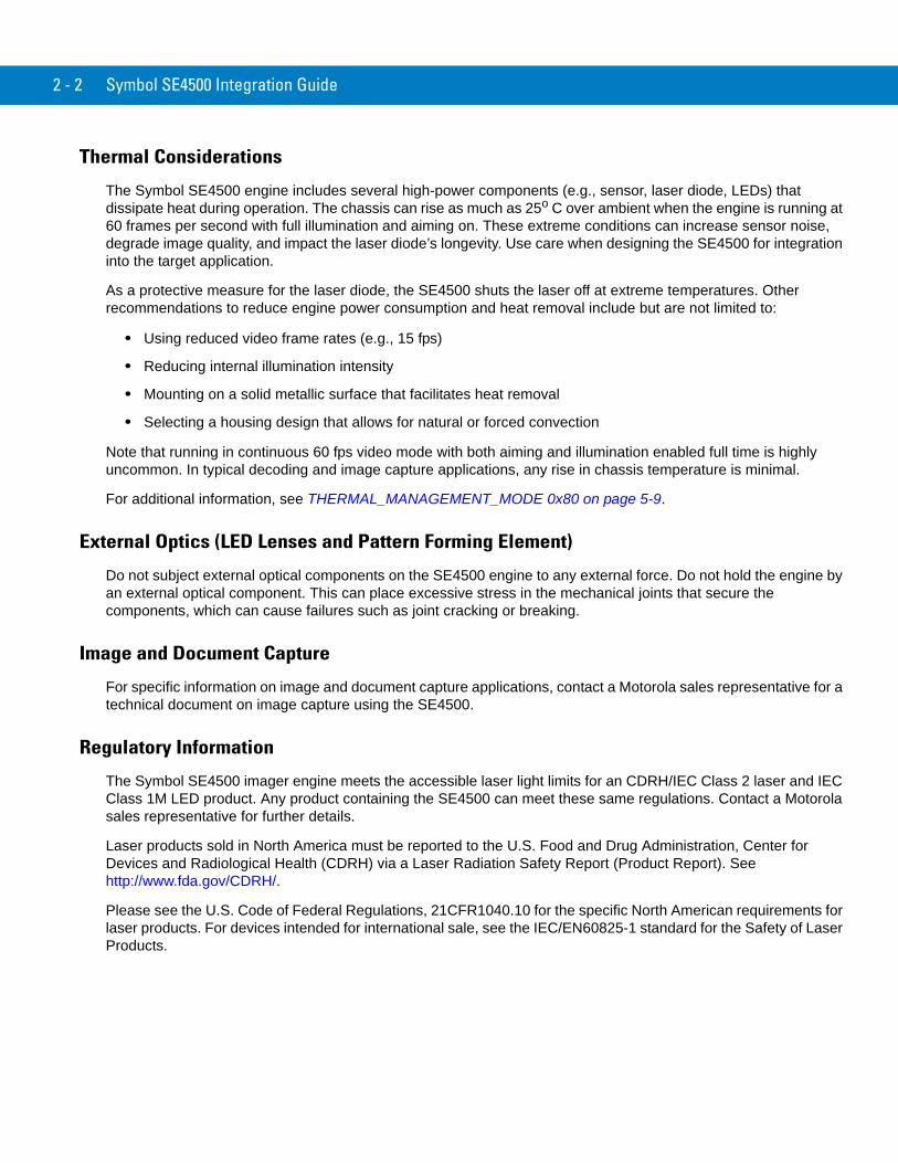
Thermal Considerations
The Symbol SE4500 engine includes several high-power components (e.g., sensor, laser diode, LEDs) that dissipate heat during operation. The chassis can rise as much as 25o C over ambient when the engine is running at 60 frames per second with full illumination and aiming on. These extreme conditions can increase sensor noise, degrade image quality, and impact the laser diode’s longevity. Use care when designing the SE4500 for integration into the target application.
As a protective measure for the laser diode, the SE4500 shuts the laser off at extreme temperatures. Other recommendations to reduce engine power consumption and heat removal include but are not limited to:
• Using reduced video frame rates (e.g., 15 fps)
• Reducing internal illumination intensity
• Mounting on a solid metallic surface that facilitates heat removal
• Selecting a housing design that allows for natural or forced convection
Note that running in continuous 60 fps video mode with both aiming and illumination enabled full time is highly uncommon. In typical decoding and image capture applications, any rise in chassis temperature is minimal.
For additional information, see THERMAL_MANAGEMENT_MODE 0x80 on page 5-9.
External Optics (LED Lenses and Pattern Forming Element)
Do not subject external optical components on the SE4500 engine to any external force. Do not hold the engine by an external optical component. This can place excessive stress in the mechanical joints that secure the components, which can cause failures such as joint cracking or breaking.
Image and Document Capture
For specific information on image and document capture applications, contact a Motorola sales representative for a technical document on image capture using the SE4500.
Regulatory Information
The Symbol SE4500 imager engine meets the accessible laser light limits for an CDRH/IEC Class 2 laser and IEC Class 1M LED product. Any product containing the SE4500 can meet these same regulations. Contact a Motorola sales representative for further details.
Laser products sold in North America must be reported to the U.S. Food and Drug Administration, Center for Devices and Radiological Health (CDRH) via a Laser Radiation Safety Report (Product Report). See http://www.fda.gov/CDRH/.
Please see the U.S. Code of Federal Regulations, 21CFR1040.10 for the specific North American requirements for laser products. For devices intended for international sale, see the IEC/EN60825-1 standard for the Safety of Laser Products.
Installation 2 - 3
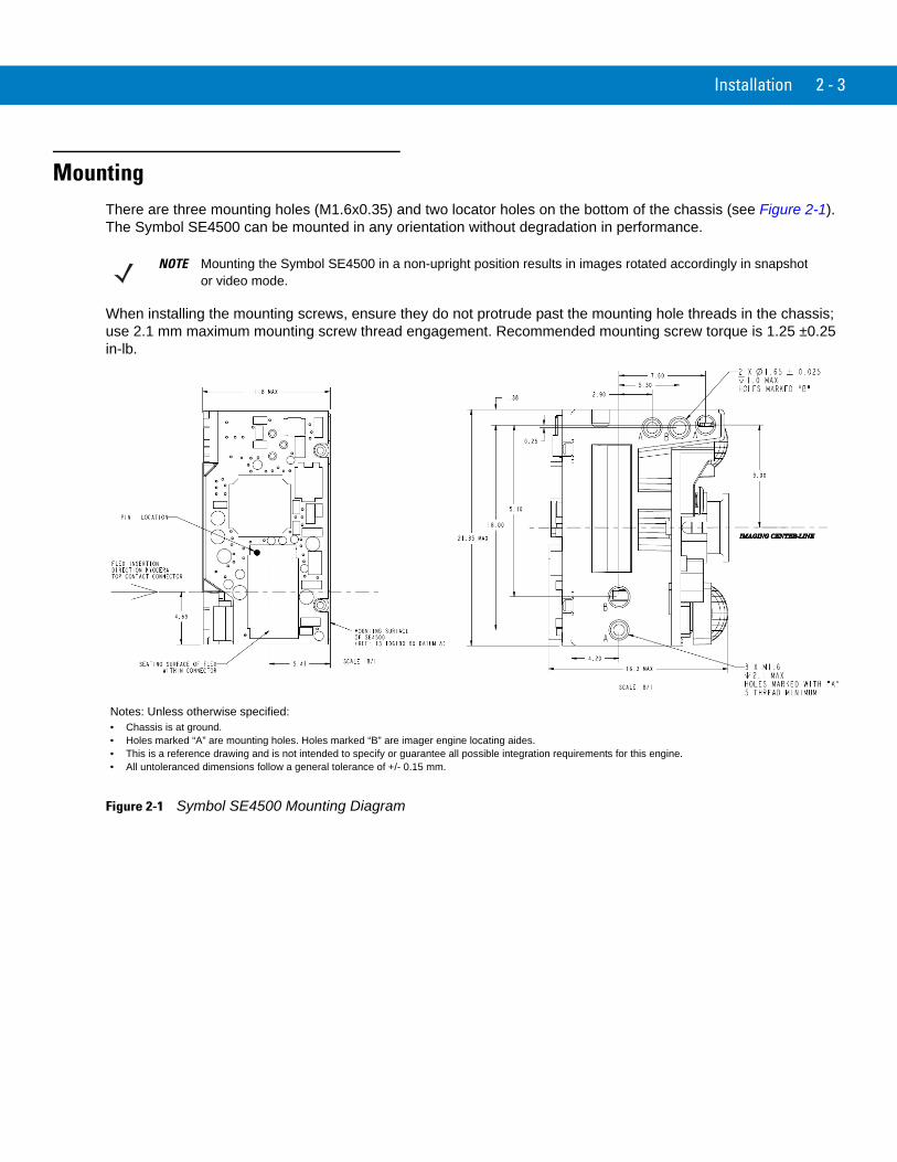
MountingThere are three mounting holes (M1.6x0.35) and two locator holes on the bottom of the chassis (see Figure 2-1). The Symbol SE4500 can be mounted in any orientation without degradation in performance.
When installing the mounting screws, ensure they do not protrude past the mounting hole threads in the chassis; use 2.1 mm maximum mounting screw thread engagement. Recommended mounting screw torque is 1.25 ±0.25 in-lb.
Figure 2-1 Symbol SE4500 Mounting Diagram
NOTE Mounting the Symbol SE4500 in a non-upright position results in images rotated accordingly in snapshot or video mode.
Notes: Unless otherwise specified:• Chassis is at ground.• Holes marked “A” are mounting holes. Holes marked “B” are imager engine locating aides. • This is a reference drawing and is not intended to specify or guarantee all possible integration requirements for this engine.• All untoleranced dimensions follow a general tolerance of +/- 0.15 mm.

2 - 4 Symbol SE4500 Integration Guide
Housing Design
Design the engine’s housing so that internal reflections from the aiming and illumination system are not directed back toward the engine. The reflections from the window or housing can cause problems, and for particular window tilt angles, these reflections can bounce off the top or bottom of the housing and reach the engine. Also, keep all housing elements outside the engine clear aperture (see Figure 2-2 on page 2-7). Avoid any bright objects around the engine that can be reflected by a tilted window into the engine field of view and appear in a captured image.
Recommended Exit Window Information on page 2-8 provides minimum exit window tilt angles. These dimensional requirements can vary. Consider using baffles or matte-finished dark internal housing colors.
OpticalThe Symbol SE4500 uses a sophisticated optical system that provides imaging performance that matches or exceeds the performance of much larger imagers. However, an improperly designed enclosure, or improper selection of window material, can affect the performance of the SE4500.
Positioning the Exit Window
Position the window so that illumination system light reflected off the inside of the window is not reflected back into the engine (see Recommended Exit Window Information on page 2-8). If the designed enclosure cannot accommodate the recommended window angle, contact Motorola to discuss positioning requirements. An improperly positioned window can significantly decrease performance.
Window Positioning Options
There are two options for window positioning:
• Parallel window - This is the preferred method for imager engines. The maximum window distance is limited. Parallel window installation requires 2-sided anti-reflection coating (see Anti-Reflection Coatings on page 2-6).
• Tilted window - This is used for either laser or imager engines. Adhere to the minimum window tilt specifications in Table 2-4 on page 2-8. With tilted window installation, 2-sided anti-reflection coating is optional (see Anti-Reflection Coatings on page 2-6).
Avoiding Scratched Windows
Scratches on the window can greatly reduce the performance of the imaging system. Motorola recommends recessing the window into the housing or applying a scratch resistance coating.
NOTE Perform an opto-mechanical analysis for the housing design to ensure optimal scanning or imaging performance.
NOTE For bar code reading, use either a parallel or tilted window. For document capture applications, Motorola strongly recommends the parallel window installation. For tilted windows, dust, contamination, and scratches on the window can cause visible blemishes in the images.

Installation 2 - 5
Window Material
Many window materials that look clear can contain stresses and distortions that reduce performance. For this reason, use only cell-cast plastics or optical glass (with or without an anti reflection coating, depending on the application). Following are descriptions of three popular window materials: PMMA, ADC (CR-39TM), and chemically tempered float glass. Table 2-1 outlines the suggested window properties.
Plastic materials are not recommended for tilted windows since surface scratches cause image artifacts. Colored windows are not recommended if motion detection mode is required since it reduces engine sensitivity to the moving target.
Cell Cast Acrylic (ASTM: PMMA)
Cell Cast Acrylic, or Poly-methyl Methacrylic (PMMA) is fabricated by casting acrylic between two precision sheets of glass. This material has very good optical quality, reasonably good impact resistance and low initial cost, but is relatively soft and susceptible to attack by chemicals, mechanical stresses, and UV light. Therefore polysiloxane coating is strongly recommended. Acrylic can be laser cut into odd shapes and ultrasonically welded.
Cell Cast ADC (ASTM: ADC)
Also known as CR-39TM, Allyl Diglycol Carbonate (ADC) is a thermal-setting plastic produced by cell-casting. Most plastic eyeglasses sold today are uncoated, cell-cast CR-39. This material has excellent chemical and environmental resistance, and reasonably good impact resistance. It also has quite good surface hardness, and therefore does not have to be hard-coated, but may be coated for severe environments. This material cannot be ultrasonically welded.
Chemically Tempered Float Glass
Glass is a hard material that provides excellent scratch and abrasion resistance. However, unannealed glass is brittle. Increasing flexibility strength with minimal optical distortion requires chemical tempering. Glass cannot be ultrasonically welded and is difficult to cut into odd shapes.
Table 2-1 Suggested Window Properties
Property Description
Material Clear cell-cast acrylic
Thickness 0.06 in. (1.5 mm)
Wavefront Distortion (transmission) 0.2 wavelengths peak-to-valley maximum and 0.04 λ maximum rms over any 0.08 in. diameter within the clear aperture
Clear Aperture To extend to within 0.04 in. of the edges all around
Surface Quality 60-20 scratch/dig

2 - 6 Symbol SE4500 Integration Guide
Commercially Available Coatings
Anti-Reflection Coatings
Anti-reflection coatings can be used for stray light control or to achieve maximum working range, and can be applied to the inside and/or outside of the window to reduce the amount of light reflected off the window back into the engine. However, they are expensive and have very poor abrasion and scratch resistance.
Polysiloxane Coating
Polysiloxane type coatings are applied to plastic surfaces to improve the surface resistance to both scratch and abrasion. To apply, dip and air dry in an oven with filtered hot air.
To gauge a window's durability, use ASTM standard D1044, Standard Test Method for Resistance of Transparent Plastics to Surface Abrasion (the Taber Test), which quantifies abrasion resistance as a percent increase in haze after a specified number of cycles and load. Lower values of the increase in haze correspond to better abrasion and scratch resistance. See Table 2-2.
A Word About Coatings
If using an anti-reflective (AR) coating, the specifications in Table 2-3 apply. Polysiloxane coating is not required. Recess the exit window to minimize scratches and digs.
Table 2-2 Taber Test Results on Common Exit Window Materials
Sample Haze 100 cycles
Haze 500 cycles
Abrasion Resistance
Chemically Tempered Float Glass 1.20% 1.50% Best
PMMA with Polysiloxane Hardcoat 3% 10%
ADC 5% 30%
PMMA 30% Worst
* All measurements use a 100 gram load and CS-10F Abraser.
Table 2-3 AR Coatings Specifications
Specification Description
Material Both tempered glass and plastic (e.g., CR-39 or hard coated acrylic) exit windows can be AR coated. AR coated glass is easier and more durable because of a better adhesion property on the glass structure. In addition, it can be more cost effective to put an AR coating on the glass substrate rather than on the plastic.
AR Coating Specification • One side tempered AR coating: 92% minimum within spectrum range from 450 nm to 700 nm.
• Double side AR coating: One side AR coating must be 97% minimum within spectrum range from 450 nm to 700 nm.
• For parallel windows, see Figure 2-3 on page 2-8.

Installation 2 - 7
Optical Path and Exit Window
Figure 2-2 Symbol SE4500 Optical Path and Exit Window
Note: Clipping of the engine clear aperture is not permitted.
2 - 8 Symbol SE4500 Integration Guide
Recommended Exit Window Information
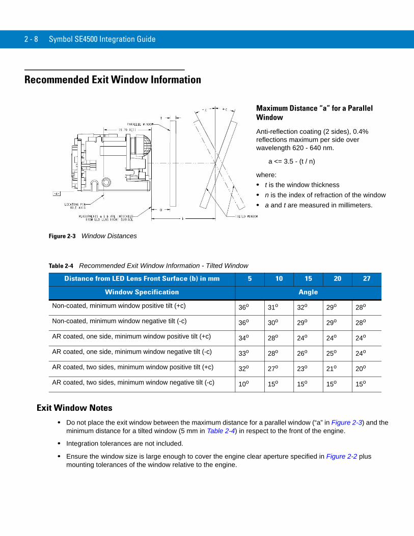
Figure 2-3 Window Distances
Exit Window Notes
• Do not place the exit window between the maximum distance for a parallel window (“a” in Figure 2-3) and the minimum distance for a tilted window (5 mm in Table 2-4) in respect to the front of the engine.
• Integration tolerances are not included.
• Ensure the window size is large enough to cover the engine clear aperture specified in Figure 2-2 plus mounting tolerances of the window relative to the engine.
Table 2-4 Recommended Exit Window Information - Tilted Window
Distance from LED Lens Front Surface (b) in mm 5 10 15 20 27
Window Specification Angle
Non-coated, minimum window positive tilt (+c) 36o 31o 32o 29o 28o
Non-coated, minimum window negative tilt (-c) 36o 30o 29o 29o 28o
AR coated, one side, minimum window positive tilt (+c) 34o 28o 24o 24o 24o
AR coated, one side, minimum window negative tilt (-c) 33o 28o 26o 25o 24o
AR coated, two sides, minimum window positive tilt (+c) 32o 27o 23o 21o 20o
AR coated, two sides, minimum window negative tilt (-c) 10o 15o 15o 15o 15o
Maximum Distance “a” for a Parallel Window
Anti-reflection coating (2 sides), 0.4% reflections maximum per side over wavelength 620 - 640 nm.
a <= 3.5 - (t / n)
where: • t is the window thickness• n is the index of refraction of the window• a and t are measured in millimeters.

Chapter 3 Specifications
IntroductionThis chapter provides the technical specifications of the Symbol SE4500, including decode zone and exit window characteristics.
Technical Specifications
Table 3-1 Symbol SE4500 Technical Specifications
Item Description
Power Requirements - Input Voltage 3.3 V ± 0.3 V at 23° C
Operating Mode Supply Currents (conditions VCC=VCC_SENSOR=VCC_ILLUM = 3.3VDC) (at 23° C):
Low Power Idle Image Acquisition Illumination Enabled Maximum Operating Current
500 μA18 mA80 mA200 mA250 mA (aiming on during exposure, illumination enabled)
Maximum Sensor Power Supply Noise*(at 23° C)
100 mVp-p (3.3 V, 10 Hz - 100 kHz) for decoding30 mVp-p (3.3 V, 10 Hz - 100 kHz) for image capture
Optical Resolutions HD focus: 3.0 mil (Code 39), 4.0 mil (PDF417)DL focus: 4.0 mil (Code 39), 5.0 mil (PDF417)SR focus: 5.0 mil (Code 39), 6.7 mil (PDF417)
*For better image quality in image capture applications, use an additional filter on VCC_SENSOR. For additional performance improvement, provide a separately regulated 3.3 V supply for the sensor.

3 - 2 Symbol SE4500 Integration Guide
Specular Dead Zone Illumination OnIllumination Off
Up to 20º depending on target distance and substrate glossinessNone
Skew Tolerance ± 60º (see Figure 3-1 on page 3-3)
Pitch Angle ± 60º (see Figure 3-1 on page 3-3)
Roll 360º (see Figure 3-1 on page 3-3)
Ambient Light Immunity (Sunlight) 9000 ft. candles (96,900 lux)
Imaging SensorImage Resolution Gray Scale Field of View (FOV)
752 H x 480 V pixels (Wide VGA) 256 levels (8 bits per pixel)SE4500-SR: 39.6º horizontal, 25.7º verticalSE4500-DL: 39.2º horizontal, 25.4º verticalSE4500-HD: 38.4º horizontal, 24.9º vertical
Focusing Distance from Front of Engine SRDLHD
8 in. / 20.3 cm5.3 in. / 13.5 cm2.9 in. / 7.4 cm
Aiming Element Visible Laser Diode (VLD) Central Dot Optical PowerPattern Angle
655 ± 10 nm 0.6 mW (typical) 40º horizontal, 30º vertical
Illumination System LEDs Pattern Angle
625 ± 5 nm (dominant wavelength)60º x 40º at 80% center intensity
Shock 2000 G ± 5% applied via any mounting surface at -30º and 55º C for a period of 0.85 ± 0.05 msec2500 G ± 5% applied via any mounting surface at 23º C for a period of 0.85 ± 0.05 msec
Vibration Unpowered SE4500 withstands a random vibration along each of the X, Y, and Z axes for a period of one hour per axis (6 G rms), defined as follows:
20 to 80 Hz Ramp up at 0.04 G2/Hz at 3 dB/octave
80 to 350 Hz 0.04 G2/Hz
350 Hz to 2 kHz Ramp down at 0.04 G2/Hz at 3 dB/octave
ESD ± 2 kV @ connector
Laser Safety Class CDRH / IEC Class 2
LED Class IEC Class 1M
Table 3-1 Symbol SE4500 Technical Specifications (Continued)
Item Description
Specifications 3 - 3
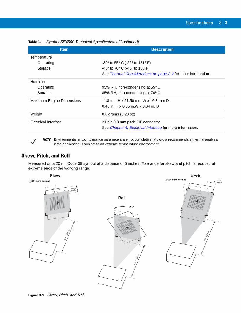
Skew, Pitch, and RollMeasured on a 20 mil Code 39 symbol at a distance of 5 inches. Tolerance for skew and pitch is reduced at extreme ends of the working range.
Figure 3-1 Skew, Pitch, and Roll
Temperature Operating Storage
-30º to 55º C (-22º to 131º F) -40º to 70º C (-40º to 158ºF)See Thermal Considerations on page 2-2 for more information.
Humidity Operating Storage
95% RH, non-condensing at 55º C 85% RH, non-condensing at 70º C
Maximum Engine Dimensions 11.8 mm H x 21.50 mm W x 16.3 mm D0.46 in. H x 0.85 in.W x 0.64 in. D
Weight 8.0 grams (0.28 oz)
Electrical Interface 21 pin 0.3 mm pitch ZIF connector See Chapter 4, Electrical Interface for more information.
Table 3-1 Symbol SE4500 Technical Specifications (Continued)
Item Description
NOTE Environmental and/or tolerance parameters are not cumulative. Motorola recommends a thermal analysis if the application is subject to an extreme temperature environment.
Skew Pitch
Roll
+ 60° from normal + 60° from normal
360°

3 - 4 Symbol SE4500 Integration Guide
Decode Zones
Symbol SE4500-SR
Figure 3-2 shows the decode zone for the Symbol SE4500-SR. Typical values appear. Table 3-2 lists the typical and guaranteed distances for selected bar code densities. The minimum element width (or “symbol density”) is the width in mils of the narrowest element (bar or space) in the symbol.
Figure 3-2 Symbol SE4500-SR Decode Zone
In.cm
0
20 mil Code 39
Depth of Field
24.7
5 10 15 20 250 12.7 25.4 38.1 50.8 63.5
13 mil (100% UPC)
14.7
1.6 15.5
15 mil PDF417
0
cmWidth
of
Field
0
4.5 11.4
9 22.9
22.9
*
*
* Minimum distance determined by symbol length and scan angle.
9
11.4
in.
Note: Typical performance at 73˚F (23˚C) on high quality symbols in normal room light.
Vcc = 3.3V
SE4500-SR
4.5
12.415 mil Data Matrix
2.8
10.110 mil PDF417*
10.67.5 mil Code 39*
6.67 mil PDF4173.4 7.1
5 mil Code 392.1 7.5

Specifications 3 - 5
Table 3-2 Symbol SE4500-SR Decode Distances
Symbol Density/Bar Code Type
Bar Code Content/
ContrastNote 2
Typical Working Ranges Guaranteed Working Ranges
Near Far Near Far
5.0 milCode 39
ABCDEFGH80% MRD
2.1 in5.33 cm
7.5 in19.05 cm
2.5 in6.35 cm
6.8 in17.27 cm
6.67 mil PDF417
4 Col, 20 Rows80% MRD
3.4 in8.64 cm
7.1 in18.03 cm
4.1 in10.41 cm
6.2 in15.75 cm
7.5 milCode 39
ABCDEF80% MRD
Note 1 10.6 in26.92 cm
Note 1 9.6 in24.38 cm
10 milPDF417
3 Col, 17 Rows80% MRD
Note 1 10.1 in25.65 cm
Note 1 9.0 in22.86 cm
13 milUPC-A
01234567890580% MRD
1.6 in5.08 cm
15.5 in39.37 cm
2.5 in5.08 cm
14.2 in36.07 cm
15 milPDF417
80% MRD Note 1 14.7 in37.34 cm
Note 1 13.2 in33.53 cm
15 milData Matrix
18 x 18 Modules80% MRD
2.8 in7.11 cm
12.4 in31.50 cm
20 milCode 39
12380% MRD
Note 1 24.7 in62.74 cm
Note 1 21.8 in55.37 cm
Notes:1. Near distances are field-of-view (FOV) limited.2. Contrast is measured as Mean Reflective Difference (MRD) at 670 nm.3. Working range specifications at temperature = 23°C, pitch=18°, roll=0°, skew=0°, photographic quality, ambient light ~30 ft-c, humidity 45-70% RH.

3 - 6 Symbol SE4500 Integration Guide
Symbol SE4500-DL
Figure 3-3 shows the decode zone for the Symbol SE4500-DL. Typical values appear. Table 3-3 lists the typical and guaranteed distances for selected bar code densities. The minimum element width (or “symbol density”) is the width in mils of the narrowest element (bar or space) in the symbol.
Figure 3-3 Symbol SE4500-DL Decode Zone
In.cm
0
20 mil Code 39
Depth of Field
19.7
4 8 12 16 200 10.2 20.3 30.5 40.6 50.8
13 mil (100% UPC)
11.7
1.6 12
15 mil PDF417
0
cmWidth
of
Field
0
4 10.2
8 20.3
20.3
*
*
* Minimum distance determined by symbol length and scan angle.
8
10.2
in.Note: Typical performance at 73˚F (23˚C) on high quality symbols in normal room light.
Vcc = 3.3V
SE4500-DL
4
11.215 mil Data Matrix
2.3
9.010 mil PDF417
*
9.97.5 mil Code 39*
6.67 mil PDF4171.9 6.9
5 mil Code 391.4 7.3
5 mil PDF4172.8 4.5
3 mil Code 392.7 4.2

Specifications 3 - 7
Table 3-3 Symbol SE4500-DL Decode Distances
Symbol Density/Bar Code Type
Bar Code Content/
ContrastNote 2
Typical Working Ranges Guaranteed Working Ranges
Near Far Near Far
3.0 milCode 39
80% MRD 2.7 in6.86 cm
4.2 in10.67 cm
3.3 in8.38 cm
3.7 in9.40 cm
5.0 milCode 39
ABCDEFGH80% MRD
1.4 in3.56 cm
7.3 in18.54 cm
1.7 in4.32 cm
6.7 in17.02 cm
5.0 milPDF417
80% MRD 2.8 in7.11 cm
4.5 in11.43 cm
3.4 in8.64 cm
3.9 in9.91 cm
6.67 mil PDF417
4 Col, 20 Rows80% MRD
1.9 in4.83 cm
6.9 in17.53 cm
2.5 in6.35 cm
6.2 in15.75 cm
7.5 milCode 39
ABCDEF80% MRD
Note 1 9.9 in25.15 cm
Note 1 8.8 in22.35 cm
10 milPDF417
3 Col, 17 Rows80% MRD
Note 1 9.0 in22.86 cm
Note 1 8.0 in20.32 cm
13 milUPC-A
01234567890580% MRD
1.6 in5.08 cm
12.0 in30.48 cm
2.5 in5.08 cm
10.7 in27.18 cm
15 milPDF417
80% MRD Note 1 11.7 in29.72 cm
Note 1 10.5 in26.67 cm
15 milData Matrix
18 x 18 Modules80% MRD
2.3 in5.84 cm
11.2 in28.45 cm
20 milCode 39
12380% MRD
Note 1 19.7 in50.04 cm
Note 1 17.1 in43.43 cm
Notes:1. Near distances are FOV limited.2. Contrast is measured as Mean Reflective Difference (MRD) at 670 nm.3. Working range specifications at temperature = 23°C, pitch=18°, roll=0°, skew=0°, photographic quality, ambient light ~30 ft-c, humidity 45-70%RH.

3 - 8 Symbol SE4500 Integration Guide
Symbol SE4500-HD
Figure 3-4 shows the decode zone for the Symbol SE4500-HD. Typical values appear. Table 3-4 lists the typical and guaranteed distances for selected bar code densities. The minimum element width (or “symbol density”) is the width in mils of the narrowest element (bar or space) in the symbol.
Figure 3-4 Symbol SE4500-HD Decode Zone
Depth of Field
13 mil (100% UPC)
6.4
5 mil PDF417
1.6 6.8
1.6 3.8
15 mil PDF417
0
cm
Width
of
Field
0
5.1
4.0 10.2
10.2
*
* Minimum distance deter mined by symbol length and scan angle.
4.0 in.Note: Typical perf ormance at 73°F (23°C)
on high quality symbols in nor mal room light. Vcc = 3.3V
7.5 mil Code 39* 6.1
6.67 mil PDF4171.3 4.5
10 mil PDF417* 5.1
SE4500-HD
4 mil PDF4171.8 3.5
2.0
5.12.0
3 mil Code 391.6 3.8
5 mil Code 39* 5.0
5 mil Data Matrix1.8 3.6
In .c m
00
1230.5
25.1
410.2
615.2
820.3
1025.4
11.120 mil Code 39
*
2.0 6.115 mil Data Matrix

Specifications 3 - 9
Table 3-4 Symbol SE4500-HD Decode Distances
Symbol Density/Bar Code Type
Bar Code Content/
ContrastNote 2
Typical Working Ranges Guaranteed Working Ranges
Near Far Near Far
3.0 milCode 39
80% MRD 1.6 in4.06 cm
3.8 in9.65 cm
1.8 in4.57 cm
3.4 in8.64 cm
4.0 mil PDF417
80% MRD 1.8 in4.57 cm
3.5 in8.89 cm
2.0 in5.08 cm
3.1 in7.87 cm
5.0 milCode 39
ABCDEFGH80% MRD
Note 1 5.0 in12.70 cm
Note 1 4.5 in11.43 cm
5.0 milPDF417
80% MRD 1.6 in4.06 cm
3.8 in9.65 cm
1.9 in4.83 cm
3.4 in8.64 cm
5 milData Matrix
18 x 18 Modules80% MRD
1.8 in4.57 cm
3.6 in9.15 cm
6.67 mil PDF417
4 Col, 20 Rows80% MRD
1.3 in3.30 cm
4.5 in11.43 cm
1.4 in3.30 cm
4.0 in11.43 cm
7.5 milCode 39
ABCDEF80% MRD
Note 1 6.1 in15.49 cm
Note 1 5.5 in15.49 cm
10 milPDF417
3 Col, 17 Rows80% MRD
Note 1 5.1 in12.95 cm
Note 1 4.5 in12.95 cm
13 milUPC-A
01234567890580% MRD
1.6 in4.06 cm
6.8 in17.27 cm
2.5 in4.06 cm
6.1 in17.27 cm
15 milPDF417
80% MRD Note 1 6.4 in16.26 cm
Note 1 5.7 in16.26 cm
15 milData Matrix
18 x 18 Modules80% MRD
2.0 in5.08 cm
6.1 in15.49 cm
20.0 milCode 39
12380% MRD
Note 1 11.1 in28.19 cm
Note 1 9.7 in28.19 cm
Notes:1. Near distances are FOV limited.2. Contrast is measured as Mean Reflective Difference (MRD) at 670 nm.3. Working range specifications at temperature = 23°C, pitch=18°, roll=0°, skew=0°, photographic quality, ambient light ~30 ft-c, humidity 45-70% RH.

3 - 10 Symbol SE4500 Integration Guide

Chapter 4 Electrical Interface
IntroductionTable 4-1 lists the pins and signals of the 21-pin connector on the Symbol SE4500. See Figure 2-1 on page 2-3 for the pin 1 location on the rear of the engine, on the side opposite the aiming/illumination system.
Table 4-1 Symbol SE4500 Signal Information
Pin Number SE4500 Signal Name I/O Note
1 GND - Ground
2 GND - Ground
3 I2C_CLK I I2C Clock
4 I2C_DATA I/O I2C Data
5 VSYNC O Vertical sync
6 PIX_DATA_7 O Sensor Pixel Data - MSB
7 PIX_DATA_6 O Sensor Pixel Data
8 PIX_DATA_5 O Sensor Pixel Data
9 PIX_DATA_4 O Sensor Pixel Data
10 PIX_DATA_3 O Sensor Pixel Data
11 PIX_DATA_2 O Sensor Pixel Data
12 PIX_DATA_1 O Sensor Pixel Data
13 PIX_DATA_0 O Sensor Pixel Data - LSB
14 EXT_ILLUM_EN O External illumination trigger
15 VCC_SENSOR - WVGA sensor power
16 VCC - Laser and logic power
17 VCC_ILLUM - Illumination power
18 HSYNC O Horizontal sync
19 GND - Ground
20 PIXCLK O Sensor pixel clock
21 GND - Ground

4 - 2 Symbol SE4500 Integration Guide
Connector DrawingsFor detailed connector information, refer to the manufacturer’s specifications.
Figure 4-1 21-Pin ZIF Connector (SE4500 Imager to Flex), Motorola p/n 50-12100-2193 (Kyocera 6283 Series)
For prevention against an opencirciut in being bent, thetapered areas are laid as indicated.
R shape foreasy FPCinsertion.
For protection against an open circuit in being bent, the tapered areas are laid as indicated.
Electrical Interface 4 - 3
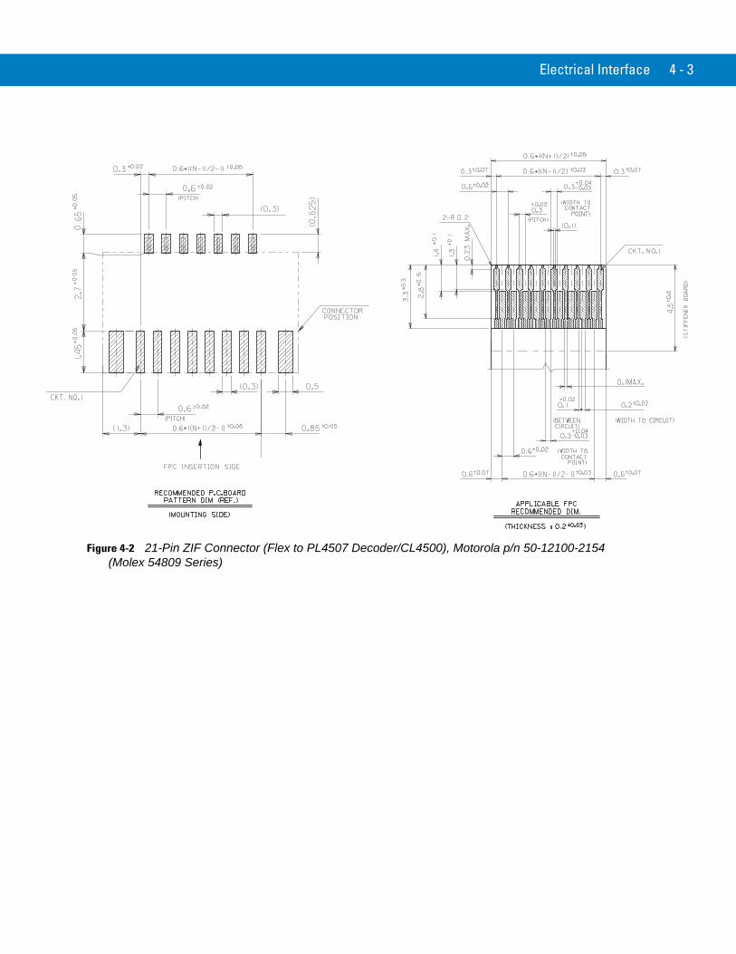
Figure 4-2 21-Pin ZIF Connector (Flex to PL4507 Decoder/CL4500), Motorola p/n 50-12100-2154 (Molex 54809 Series)

4 - 4 Symbol SE4500 Integration Guide
Figure 4-3 21-Pin ZIF Connector (Flex to PL4507 Decoder/CL4500), Motorola p/n 50-12100-2154 (Molex 54809 Series) (continued)

Electrical Interface 4 - 5
Figure 4-4 Symbol SE4500 to PL4507 Decoder/CL4500 21-Pin Flex, Motorola p/n 15-113896-01

4 - 6 Symbol SE4500 Integration Guide
Chapter 5 Control Interface
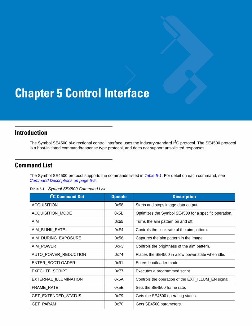
Introduction The Symbol SE4500 bi-directional control interface uses the industry-standard I2C protocol. The SE4500 protocol is a host-initiated command/response type protocol, and does not support unsolicited responses.
Command ListThe Symbol SE4500 protocol supports the commands listed in Table 5-1. For detail on each command, see Command Descriptions on page 5-5.
Table 5-1 Symbol SE4500 Command List
I2C Command Set Opcode Description
ACQUISITION 0x58 Starts and stops image data output.
ACQUISITION_MODE 0x5B Optimizes the Symbol SE4500 for a specific operation.
AIM 0x55 Turns the aim pattern on and off.
AIM_BLINK_RATE 0xF4 Controls the blink rate of the aim pattern.
AIM_DURING_EXPOSURE 0x56 Captures the aim pattern in the image.
AIM_POWER 0xF3 Controls the brightness of the aim pattern.
AUTO_POWER_REDUCTION 0x74 Places the SE4500 in a low power state when idle.
ENTER_BOOTLOADER 0x91 Enters bootloader mode.
EXECUTE_SCRIPT 0x77 Executes a programmed script.
EXTERNAL_ILLUMINATION 0x5A Controls the operation of the EXT_ILLUM_EN signal.
FRAME_RATE 0x5E Sets the SE4500 frame rate.
GET_EXTENDED_STATUS 0x79 Gets the SE4500 operating states.
GET_PARAM 0x70 Gets SE4500 parameters.

5 - 2 Symbol SE4500 Integration Guide
ILLUMINATION_CURRENT_LIMIT 0xF2 Reduces the illumination system current drawn from the host.
ILLUMINATION_DURING_EXPOSURE 0x59 Turns illumination on and off.
ILLUMINATION_POWER_LEVEL 0xF0 Sets the illumination brightness level.
IMAGE_CAPTURE_MODE 0x73 Sets the image capture mode.
IMAGE_CROPPING 0x5D Crops the output image.
IMAGE_RESOLUTION 0x5C Sets the resolution of the output image.
PICKLIST_MODE 0x7B Sets the rate of picklist frames.
PING 0x7A Used for test purposes.
POWER_MODE 0x5F Places the SE4500 in low power mode.
RD_OSC 0x53 Reads the oscillator registers.
RD_SENSOR 0x51 Reads the Micron MT9V022 registers.
RESET 0x57 Returns engine components to a default state.
THERMAL_MANAGEMENT_MODE 0x80 Dynamically adjusts the SE4500’s frame rate to reduce its internal temperature.
TIME_TO_LOW_POWER 0x75 Sets the length of time the SE4500 is idle before entering low power mode.
WR_OSC 0x52 Writes to the oscillator registers.
WR_SCRIPT 0x76 Programs more than one SE4500 command into one script.
WR_SENSOR 0x50 Writes to the Micron MT9V022 registers.
Table 5-1 Symbol SE4500 Command List (Continued)
I2C Command Set Opcode Description

Control Interface 5 - 3
TransactionsI2C transactions control the Symbol SE4500, where a transaction consists of a command followed by a response. I2C is a master/slave protocol, meaning the host initiates both transmissions.
The Symbol SE4500 typically processes a command in less than 1 ms, but some commands take up to 100 ms. For this reason, after sending a command, the host (I2C master) should request a response, and if the Symbol SE4500 does not respond the host should retry the response request for up to 100 ms. If the Symbol SE4500 does not respond within this time, a hard failure occurred.
The I2C format of these commands and responses is as follows.
I2C Command Format<I2C-Start Bit> <SLA-W> <Cmd-Opcode> <[SE4500-Cmd-Data]> <Checksum> <I2C-Stop-Bit>
where:
• I2C-Start-Bit and I2C-Stop-Bit are as defined by the I2C specification
• SLA-W is 0xB8 (Slave-Addr + Write-Op) or• Slave Address is 0x5C (or 0xB8 after shifting into 7 MSBs)• Write-Op is 0x00
• Opcode is 1 byte from the SE4500 Command Op column in Table 5-3 on page 5-11.
• [SE4500-Cmd-Data] is from the SE4500 Command Data column in Table 5-3 on page 5-11. This can be NULL.
• Checksum is a 1 byte checksum of the SE4500 Cmd Data bytes. See Command Checksum on page 5-4.
I2C Response Format<I2C-Start Bit> <SLA-R> <Rsp-Opcode> <Status> <[SE4500-Rsp-Data]> <I2C-Stop-Bit>
Where:
• I2C-Start-Bit and I2C-Stop-Bit are as defined by the I2C specification
• SLA-R is 0xB9 (Slave-Addr + Read-Op) or• Slave Address is 0x5C (or 0xB8 after shifting into 7 msb's)• Read-Op is 0x01
• Opcode is 1 byte from the SE4500 Response Op column in Table 5-3 on page 5-11.
• Status indicates whether the SE4500 successfully processed the command. See Response Status Code on page 5-4.
• [SE4500-Rsp-Data] is from the SE4500 Response Data column in Table 5-3 on page 5-11. This can be NULL.
5 - 4 Symbol SE4500 Integration Guide
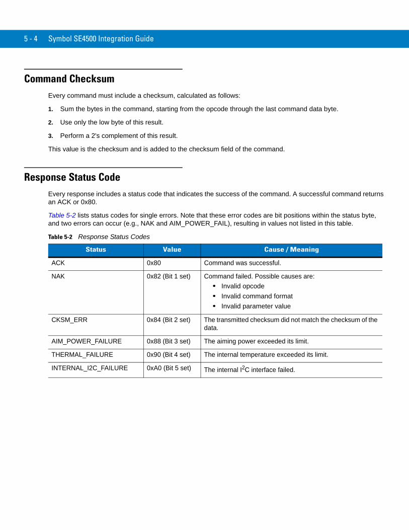
Command ChecksumEvery command must include a checksum, calculated as follows:
1. Sum the bytes in the command, starting from the opcode through the last command data byte.
2. Use only the low byte of this result.
3. Perform a 2's complement of this result.
This value is the checksum and is added to the checksum field of the command.
Response Status CodeEvery response includes a status code that indicates the success of the command. A successful command returns an ACK or 0x80.
Table 5-2 lists status codes for single errors. Note that these error codes are bit positions within the status byte, and two errors can occur (e.g., NAK and AIM_POWER_FAIL), resulting in values not listed in this table.
Table 5-2 Response Status Codes
Status Value Cause / Meaning
ACK 0x80 Command was successful.
NAK 0x82 (Bit 1 set) Command failed. Possible causes are:• Invalid opcode• Invalid command format • Invalid parameter value
CKSM_ERR 0x84 (Bit 2 set) The transmitted checksum did not match the checksum of the data.
AIM_POWER_FAILURE 0x88 (Bit 3 set) The aiming power exceeded its limit.
THERMAL_FAILURE 0x90 (Bit 4 set) The internal temperature exceeded its limit.
INTERNAL_I2C_FAILURE 0xA0 (Bit 5 set) The internal I2C interface failed.

Control Interface 5 - 5
Command Descriptions See Table 5-3 on page 5-11 for command and response formats for all Symbol SE4500 commands.
ACQUISITION 0x58
ACQUISITION Start causes the Symbol SE4500 to output image data on the camera interface. ACQUISITION Stop stops the image data output.
After receiving the Stop command, the Symbol SE4500 may not respond to subsequent commands for up to one frame time (16.6 ms at 60 fps) because the system requires the current frame to complete before the engine processes new commands. Issuing commands during this time results in unacknowledged I2C commands, requiring command retries.
ACQUISITION_MODE 0x5B
Optimizes the engine’s behavior for bar code decoding, image capture, motion detection, or aiming pattern capture.
AIM 0x55
Turns the aiming pattern on and off. AIM only turns aiming on if acquisition is started. Setting AIM On while acquisition is stopped does not turn aiming on, although it turns aiming on upon the next ACQUISITION Start command.
AIM_BLINK_RATE 0xF4
Controls the blink rate of the aiming pattern. The aiming pattern only blinks when AIM is enabled. The default is Always On.
This command takes two parameters as follows:
• Byte 1 = Number of frames the aiming pattern remains on; 0 = Always On
• Byte 2 = Number of frames the aiming pattern is off.
Blink rate/times depend on the frame rate, for example:
• At 60 fps, to blink at 1/3 seconds on and 2/3 seconds off, set Byte 1 to 20 and Byte 2 to 40.
• At 30 fps, to blink at 1/3 seconds on and 2/3 seconds off, set Byte 1 to 10 and Byte 2 to 20.
AIM_DURING_EXPOSURE 0x56
When enabled, this keeps the aiming pattern on when capturing an image, meaning the pattern is visible in the image. When disabled, the aiming pattern is not visible in acquired images. The default is disabled.
Enabling AIM_DURING_EXPOSURE has no effect unless AIM is also on. Enabling AIM_DURING_EXPOSURE while acquisition is stopped does not turn aiming on, although it turns aiming on upon the next ACQUISITION Start command.
NOTE When using Picklist Mode, AIM_BLINK_RATE must remain at its default.

5 - 6 Symbol SE4500 Integration Guide
AIM_POWER 0xF3
Controls the brightness of the aiming pattern. The default is 0x0 or Always On.
A value of 0x0 indicates that exposure and readout times control the aim's duration (and power or brightness).
Values of 0x1 - 0xFF indicate the aiming duration increments from 0.5 ms upward in 0.5 ms intervals; however, exposure and readout times clip its maximum value.
AUTO_POWER_REDUCTION 0x74
Places the Symbol SE4500 in a low power state when idle for the duration of time specified by the TIME_TO_LOW_POWER command. Any I2C command wakes the Symbol SE4500 from low power mode.
The Symbol SE4500 is considered idle only if acquisition is stopped. While acquisition is started, the Symbol SE4500 does not automatically enter low power mode.
EXECUTE_SCRIPT 0x77
After programming a script (via the WR_SCRIPT command), use this command to execute it.
EXTERNAL_ILLUMINATION 0x5A
Controls operation of the EXT_ILLUM_EN signal on the Symbol SE4500 host connector.
FRAME_RATE 0x5E
Sets the Symbol SE4500 frame rate.
GET_EXTENDED_STATUS 0x79
The Symbol SE4500 internally tracks various operating states and stores these states in the extended status structure. This command gets these states from the SE4500. The following are the operating conditions and descriptions.
Each operating condition has 2 bits in the extended status:
• Instantaneous bit - set if the condition exists when the GET_EXTENDED_STATUS command is issued. If the condition occurred in the past and no longer exists, the bit is cleared. These bits are reported in the first byte of the extended status data.
• Latched bit - set when the condition is first detected and remains set (even if the condition no longer exists) until the GET_EXTENDED_STATUS command is issued, which clears the bit. If a latched bit is set when the GET_EXTENDED_STATUS command is issued, this indicates the condition occurred at some point since the last GET_EXTENDED_STATUS command. These bits are reported in the second byte of the extended status data.
• Note that these conditions are bit positions within the extended status bytes; these conditions can occur simultaneously resulting in values not shown below.

Control Interface 5 - 7
Operating States (Individual Bytes)
• 0x01: The internal temperature is approaching the threshold at which it can affect laser operation.
• 0x08: The internal temperature has reached the threshold at which it affects laser operation.
• 0x02, 0x04, 0x20, 0x40: Internal warning.
GET_PARAM 0x70
Allows a host to read out parameters stored in the Symbol SE4500 (non-volatile memory). See Table 5-4 on page 5-14 for a list of these parameters.
ILLUMINATION_CURRENT_LIMIT 0xF2
Use this to reduce the maximum current draw on VCC_ILLUM. Higher values (lower currents) reduce illumination brightness.
ILLUMINATION_DURING_EXPOSURE 0x59
Turns Illumination on and off. Illumination only turns on if acquisition is started. Enabling illumination while acquisition is stopped does not turn illumination on, although it turns on illumination upon the next ACQUISITION Start command.
ILLUMINATION_POWER_LEVEL 0xF0
Sets the Symbol SE4500's illumination power (brightness) level. Settings are:
• 0x00 = Lowest power level
• 0xFF = Highest power level
IMAGE_CAPTURE_MODE 0x73
Sets image capture mode to one of the following:
• Continuous (0x00) - an ACQUISITION Start command results in continuous image frames (one right after another) until you issue the ACQUISITION Stop command.
• Snapshot (0x01) - an ACQUISITION Start command results in only one image frame. Issue another ACQUISITION Start command to acquire another image/frame.
The default is Continuous.
IMAGE_CROPPING 0x5D
Crops the output image to the specified pixel edge.

5 - 8 Symbol SE4500 Integration Guide
IMAGE_RESOLUTION 0x5C
Sets the resolution of the output image. Row Bin 2 and Column Bin 2 halve the number of rows and columns, respectively, in the image. Row Bin 4 and Column Bin 4 cut the number of rows and columns by a factor of 4.
This command is cumulative, i.e., to set Row Bin 2 and Column Bin 2, use the two-command sequence:
<0x5C> <0x01> <Checksum> <0x5C> <0x03> <Checksum>
To return to Normal, use the single command:
<0x5C> <0x00> <Checksum>
PICKLIST_MODE 0x7B
Specifies the rate of picklist frames. For picklist frames, illumination is off and the aiming pattern is captured in the image, enabling you to locate (through software image processing) the aiming pattern in the image.
This command has two parameters:
• Number of Picklist Frames (referred to as M): how many consecutive Picklist frames are output.
• Number of Frames (referred to as N): how many frames before Picklist frames start again.
The default is 0,60, or 0 Picklist frames every 60 frames.
Example
Two picklist frames - every 60 frames use the arguments [<0x02> <0x3C>]
One picklist frame - every 30 frames use the arguments [<0x01> <0x1E>]
Configure PICKLIST_MODE before starting acquisition. When acquisition starts, the picklist sequence begins. The first M frames are picklist frames, and the next N-M frames are non-picklist frames. This sequences cycles every N frames. The host system must track/count every frame to determine when picklist frames and non-picklist frames occur.
In a typical triggering environment where acquisition starts with a trigger and stops with a decode (or trigger release), each trigger pull (ACQUISITION Start) restarts the picklist sequence.
Do not change PICKLIST_MODE when acquisition is started because this can result in an indeterminate number of picklist frames.
PING 0x7A
Use this command for test purposes to verify that the engine is in a powered state.
POWER_MODE 0x5F
Changes the SE4500’s power mode. Although this command offers a Full Power mode option, any command returns the Symbol SE4500 to full power mode.
NOTE This command is rejected (a NAK is sent) if acquisition is running (ACQUISITION = Start). If low power is required during acquisition, first send ACQUISITION = Stop, then POWER_MODE = Low Power.

Control Interface 5 - 9
RD_OSC 0x53
Reads oscillator registers. Refer to the DS1086L oscillator specification from Maxim (http://www.maxim-ic.com) for register descriptions.
RD_SENSOR 0x51
Reads Micron MT9V022 sensor registers. Refer to the MT9V022 specification from Micron for register descriptions.
RESET 0x57
Returns the SE4500 to a default state.
THERMAL_MANAGEMENT_MODE 0x80
When enabled, the Symbol SE4500 dynamically adjusts its frame rate (from 60 fps to 30 fps) in an attempt to reduce its internal temperature. When the internal temperature reaches a threshold, the Symbol SE4500 enters Thermal Warning state and reduces its frame rate to 30 fps. If the Symbol SE4500 returns to normal operating temperature it exits Thermal Warning and returns to 60 fps. Use the GET_EXTENDED_STATUS command to determine if the Symbol SE4500 is in Thermal Warning mode.
When disabled, the Symbol SE4500 does not dynamically change its frame rate due to temperature changes. The default is disabled.
Only use this mode when FRAME_RATE is set to 60 fps.
TIME_TO_LOW_POWER 0x75
Sets the length of time the Symbol SE4500 must be idle before it enters low power mode. This only applies if AUTO_POWER_REDUCTION is enabled.
WR_OSC 0x52
Writes directly to the oscillator IC registers. Refer to the DS1086L oscillator specification from Maxim (http://www.maxim-ic.com) for register descriptions.
Note that the Symbol SE4500 controls many oscillator registers. Using this command to write registers may conflict with Symbol SE4500 requirements, causing unpredictable behavior.

5 - 10 Symbol SE4500 Integration Guide
WR_SCRIPT 0x76
Programs more than one SE4500 command into a script, which can be executed using a single command (EXECUTE_SCRIPT). Use this method whenever possible to increase performance and timing synchronization.
There are ten scripts (Script-0 through Script-9) and a total of 150 bytes for all scripts. Exceeding these limits results in a NAK status code. The general format for this command is:
<0x76><Script#><Len> [ <C1Len><C1Op><C1Data> ] [ <C2Len><C2Op><C2Data> ][<C3Len><C3Op><C3Data> ] <Checksum>
ExampleTo program script 2 with AIM_ON, ILLUM_ON, and ACQUISITION_ON, format the WR_SCRIPT command as follows:
<0x76><0x02><0x09> [ <0x02><0x55><0x01> ] [ <0x02><0x59><0x01> ] [ <0x02><0x58><0x01> ] <0x70>
WR_SENSOR 0x50Writes directly to the Micron MT9V022 sensor registers. Refer to the MT9V022 specification from Micron for register descriptions.
Note that the Symbol SE4500 controls many sensor registers. Using this command to write sensor registers may conflict with Symbol SE4500 requirements, causing unpredictable behavior.
NOTE Brackets ( [ ] ) appear in this example for clarity only, and are not part of the commands.

Control Interface 5 - 11
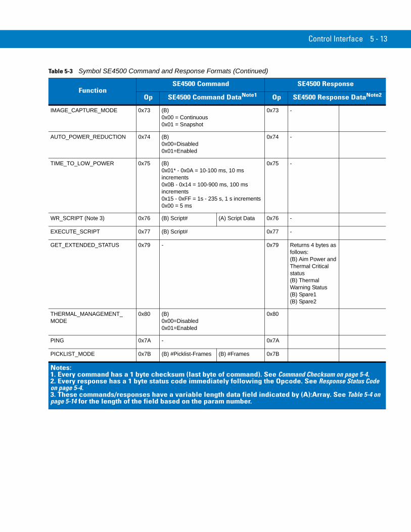
Command / Response Formats Table 5-3 depicts the command and response formats for all Symbol SE4500 commands.
In the columns SE4500 Command Data and SE4500 Response Data, the following letters identify the size of the data: (B) = Byte, (W) = Word, or (A) = Array. Words are in Little-Endian format (low byte first).
* indicates the default.
Table 5-3 Symbol SE4500 Command and Response Formats
FunctionSE4500 Command SE4500 Response
Op SE4500 Command DataNote1 Op SE4500 Response DataNote2
WR_SENSOR 0x50 (B) Register (W) Value 0x50 -
RD_SENSOR 0x51 (B) Register 0x51 (W) Value
WR_OSC 0x52 (B) Register (W) Value 0x52 -
RD_OSC 0x53 (B) Register 0x53 (W) Value
AIM 0x55 (B)0x00=Off*0x01=On
0x55 -
AIM_DURING_EXPOSURE 0x56 (B) 0x00=Off*0x01=On
0x56 -
RESET 0x57 (B) 0x00=Sensor0x01=SE4500
0x57 -
ACQUISITION 0x58 (B) 0x00=Stop0x01=Start
0x58 -
ILLUMINATION_DURING_EXPOSURE
0x59 (B)0x00=Off*0x01=On
0x59 -
EXTERNAL_ILLUMINATION 0x5A (B) 0x00=Floating Input* 0x01=On 0x02=Off 0x03=Follow Internal Illumination 0x04=Follow Trigger 0x05=Alternate with Internal Illumination
0x5A -
ACQUISITION_MODE 0x5B (B) 0x00=Barcode Decode* 0x01=Document Capture 0x02=Motion Detect 0x03=Aim Capture
0x5B -
Notes:1. Every command has a 1 byte checksum (last byte of command). See Command Checksum on page 5-4.2. Every response has a 1 byte status code immediately following the Opcode. See Response Status Code on page 5-4.3. These commands/responses have a variable length data field indicated by (A):Array. See Table 5-4 on page 5-14 for the length of the field based on the param number.

5 - 12 Symbol SE4500 Integration Guide
IMAGE_RESOLUTION 0x5C (B) 0x00=Normal* 0x01=Row Bin 2 0x02=Row Bin 4 0x03=Column Bin 20x04=Column Bin 4
0x5C -
IMAGE_CROPPING 0x5D (B) Edge 0x00=Top 0x01=Right 0x02=Bottom0x03-Left
(W) Value (No. of pixels to crop)
0x5D -
FRAME_RATE 0x5E (B) 0x00=60fps* 0x01=30fps 0x02=15fps 0x03=10fps
0x5E -
POWER_MODE 0x5F (B)0x00=Full* 0x01=Low
0x5F -
ILLUMINATION_POWER_LEVEL 0xF0 (B)0x00=Lowest 0xFF=Highest Power Level0x9E=Default
0xF0 -
ILLUMINATION_CURRENT_LIMIT
0xF2 (B)0x00=Highest current0xFF=Lowest current
0xF2 -
AIM_POWER 0xF3 (B) 0x00* = Aim's duration is controlled by Exposure and Readout times.0x01-0xFF = Aim's duration increments from 0.5 ms in 0.5 ms duration, its maximum value controlled by Exposure and Readout time.
0xF3 -
AIM_BLINK_RATE 0xF4 (B) On Timein ~17ms increments
(B) Off Time in ~17ms increments
0xF4 -
ENTER_BOOTLOADER 0x91 (A) Signature (3 bytes: 0xAA, 0x50, 0x5F)
0x91
GET_PARAM (see Note 3 and Table 5-4)
0x70 (W) Param# 0x70 (W) Param# (A) Param Data (Note 3)
Table 5-3 Symbol SE4500 Command and Response Formats (Continued)
FunctionSE4500 Command SE4500 Response
Op SE4500 Command DataNote1 Op SE4500 Response DataNote2
Notes:1. Every command has a 1 byte checksum (last byte of command). See Command Checksum on page 5-4.2. Every response has a 1 byte status code immediately following the Opcode. See Response Status Code on page 5-4.3. These commands/responses have a variable length data field indicated by (A):Array. See Table 5-4 on page 5-14 for the length of the field based on the param number.
Control Interface 5 - 13
IMAGE_CAPTURE_MODE 0x73 (B) 0x00 = Continuous 0x01 = Snapshot
0x73 -
AUTO_POWER_REDUCTION 0x74 (B)0x00=Disabled 0x01=Enabled
0x74 -
TIME_TO_LOW_POWER 0x75 (B) 0x01* - 0x0A = 10-100 ms, 10 ms increments0x0B - 0x14 = 100-900 ms, 100 ms increments0x15 - 0xFF = 1s - 235 s, 1 s increments0x00 = 5 ms
0x75 -
WR_SCRIPT (Note 3) 0x76 (B) Script# (A) Script Data 0x76 -
EXECUTE_SCRIPT 0x77 (B) Script# 0x77 -
GET_EXTENDED_STATUS 0x79 - 0x79 Returns 4 bytes as follows:(B) Aim Power and Thermal Critical status(B) Thermal Warning Status(B) Spare1(B) Spare2
THERMAL_MANAGEMENT_MODE
0x80 (B) 0x00=Disabled 0x01=Enabled
0x80
PING 0x7A - 0x7A
PICKLIST_MODE 0x7B (B) #Picklist-Frames (B) #Frames 0x7B
Table 5-3 Symbol SE4500 Command and Response Formats (Continued)
FunctionSE4500 Command SE4500 Response
Op SE4500 Command DataNote1 Op SE4500 Response DataNote2
Notes:1. Every command has a 1 byte checksum (last byte of command). See Command Checksum on page 5-4.2. Every response has a 1 byte status code immediately following the Opcode. See Response Status Code on page 5-4.3. These commands/responses have a variable length data field indicated by (A):Array. See Table 5-4 on page 5-14 for the length of the field based on the param number.

5 - 14 Symbol SE4500 Integration Guide
Table 5-4 Symbol SE4500 Parameter Numbers and Data Formats
Parameter Description Number Length (bytes)
MODEL_NUMBER Engine model number 0 18
SERIAL_NUMBER Engine serial number 1 16
DATE_MANUFACTURE Engine manufacturing date 2 7
DATE_SERVICE Engine service date 3 7
SCANNER_BOOTLOADER_FIRMWARE_VERSION Engine bootloader version 10 8
SCANNER_PRODUCTCODE_FIRMWARE_VERSION Engine firmware version 20004 8
ENGINE_ID Engine ID number 20005 1
HARDWARE_VERSION Engine hardware version 20006 1
DEVICE_CLASS Engine device class. 20007 18
GUID Generally Unique ID 14 32

Chapter 6 Application Notes
Introduction This chapter includes image acquisition and power consumption information. LED illumination is required for decoding.
Image AcquisitionThe Symbol SE4500 contains a wide VGA CMOS sensor. Figure 6-1 and Figure 6-2 illustrate pixel output format, and Figure 6-3 and Figure 6-4 show basic timing information.
Figure 6-1 Pixel Output Format
8 dark, 1 light dummy rows
2 dummy columns
(0,0)
26 dark, 1 lightdummy columns
2 dummy rows

6 - 2 Symbol SE4500 Integration Guide
Output Data Format
Image data can be read out in a progressive scan or in interlaced scan mode. Vertical and horizontal blanking surrounds valid image data, as shown in Figure 6-2.
Figure 6-2 Image Readout
Output Data Timing
Data output is synchronized with the PIXCLK output. When LINE_VALID is high, one 10-bit pixel datum is output every PIXCLK period.
Figure 6-3 Row Timing and FRAME_VALID / LINE_VALID Signals
Figure 6-4 Pixel Data Timing Example
P4,1 P4,2 P4,3 .....................................P 4,n-1 P4,nP6,0 P6,1 P6,2 .....................................P 6,n-1 P6,n
00 00 00 .................. 00 00 0000 00 00 .................. 00 00 00
Pm-2,0 Pm-2,2 .....................................P m-2,n-2 Pm-2,nPm,2 Pm,2 .....................................P m,n-1 Pm,n
00 00 00 .................. 00 00 0000 00 00 .................. 00 00 00
00 00 00 .................. 00 00 0000 00 00 .................. 00 00 00
00 00 00 ..................................... 00 00 0000 00 00 ..................................... 00 00 00
00 00 00 ............................................................................................. 00 00 0000 00 00 ............................................................................................. 00 00 00
VALID IMAGE - Even Field
P5,1 P5,2 P5,3 .....................................P 5,n-1 P5,nP7,0 P7,1 P7,2 .....................................P 7,n-1 P7,n
Pm-3,1 Pm-3,2 .....................................P m-3,n-1 Pm-3,nPm,1 Pm,1 .....................................P m,n-1 Pm,n
FIELD BLANKING
P0,0 P0,1 P0,2 .....................................P 0,n-1 P0,nP1,0 P1,1 P1,2 .....................................P 1,n-1 P1,n
00 00 00 .................. 00 00 0000 00 00 .................. 00 00 00
Pm-1,0 Pm-1,1 .....................................P m-1,n-1 Pm-1,nPm,0 Pm,1 .....................................P m,n-1 Pm,n
00 00 00 .................. 00 00 0000 00 00 .................. 00 00 00
00 00 00 .................. 00 00 0000 00 00 .................. 00 00 00
00 00 00 .................. 00 00 0000 00 00 .................. 00 00 00
00 00 00 ..................................... 00 00 0000 00 00 ..................................... 00 00 00
00 00 00 ..................................... 00 00 0000 00 00 ..................................... 00 00 00
VALID IMAGE HORIZONTALBLANKING
VERTICAL BLANKINGVERTICAL/HORIZONTAL
BLANKING
VALID IMAGE - Odd Field
VERTICAL BLANKING
HORIZONTALBLANKING
Interlaced Scan Progressive Scan
P1 A Q A Q A P2
. . .. . .
. . .. . .
. . .. . .
Num ber of master clocks
FRAME_VALID
LINE_VALID
LINE_VALID
PIX CLK
D OUT (9:0) P0(9:0)
P1(9:0)
P2(9:0)
P3(9:0)
P4(9:0)
Pn-1(9:0)
Pn(9:0)
Blanking Blanking
...
...
...
...
Valid Image Data

Application Notes 6 - 3
Table 6-1 Frame Time
Parameter Description Pixel Clock Master Clocks Time Units
A Active data time 752 752 28.02 µs
P1 Frame start blanking 71 71 2.66 µs
P2 Frame end blanking 23 23 0.86 µs
Q Horizontal blanking 94 94 3.52 µs
A + Q Row time 846 846 31.72 µs
V Vertical blanking 38,074 38,074 1.43 ms
Nrows Frame valid time 406,080 406,080 15.23 ms
F Total frame time 444,154 444,154 16.66 ms

6 - 4 Symbol SE4500 Integration Guide
Recommended Procedures The following trigger mode procedures describe the recommended transaction sequence between a host and the Symbol SE4500. These transaction sequences use discrete commands for clarity. Replace any set of discrete commands with a multi-command EXECUTE_SCRIPT to improve throughput.
Normal Decode Mode
Level Trigger Mode Procedure
The system is initialized as follows:
• The host sends the Aim Off command.
• The host sends the Illumination Off command.
• The host sends the Acquisition Stop command.
• The host sends the Barcode Decode mode command.
• The SE4500 optimizes the image output for bar code decoding.
• The SE4500 enters standby mode (or low power mode if enabled).
Upon a trigger pull:
• The host sends the Illumination On command.
• The SE4500 exits standby mode (or low power mode if enabled).
• The host sends the Aim On command.
• The host sends the Acquisition Start command.
• The SE4500 begins outputting images.
• The host attempts to decode the images.
Upon a good decode or trigger release:
• The host sends the Acquisition Stop command.
• The SE4500 stops outputting images.
• The host sends the Aim Off command.
• The host sends the Illumination Off command.
• The SE4500 enters standby mode (or low power mode if enabled).

Application Notes 6 - 5
Picklist in Level Trigger Mode Procedure
The system is initialized as follows:
• The host sends the Aim Off command.
• The host sends the Illumination Off command.
• The host sends the Acquisition Stop command.
• The host sends the Barcode Decode mode command.
• The host sends the Picklist Mode(1,60) command
• The SE4500 optimizes the image output for bar code decoding.
• The SE4500 enters standby mode (or low power mode if enabled).
Upon a trigger pull:
• The host sends the Illumination On command.
• The SE4500 exits standby mode (or low power mode if enabled).
• The host sends the Aim On command.
• The host sends the Acquisition Start command.
• The SE4500 begins outputting images. Starting with the first frame, every 60th frame is a picklist frame (1,61,121,181 …).
• The host attempts to decode the images.
Upon a good decode or trigger release:
• The host sends the Acquisition Stop command.
• The SE4500 stops outputting images.
• The host sends the Aim Off command.
• The host sends the Illumination Off command.
• The SE4500 enters standby mode (or low power mode if enabled).

6 - 6 Symbol SE4500 Integration Guide
Presentation Mode Procedure
The system is initialized as follows:
• The host sends the Aim Off command.
• The host sends the Illumination On command.
• The host sends the Illumination Power Off command (Off is the default, but power can be set low to allow motion detection in darkness).
• The host sends the Acquisition Start command (and never sends the Stop command).
• The host sends the Motion Detect mode command.
• The SE4500 optimizes the image output for motion detection.
• The SE4500 continuously outputs images.
• In this mode, the SE4500 does not enter standby or low power mode.
Upon the host detecting motion:
• The host sends the Aim On command.
• The host sends the Illumination Power Full command.
• The host sends the Barcode Decode mode command.
• The SE4500 optimizes the image output for bar code decoding.
• The host attempts to decode the images.
Upon a good decode:
• The host sends the Aim Off command.
• The host sends the Illumination Power Off command (Off is the default, but power can be set low to allow motion detection in darkness).
• The host sends the Motion Detect mode command.
• The SE4500 optimizes the image output for motion detection.
During this mode:
• The SE4500 does not automatically enter standby or low power mode.
• The host uses the Power Mode command to put the SE4500 into a low power mode (for support of Bus Powered USB).

Application Notes 6 - 7
Auto-AIM Mode Procedure
The system is initialized as follows:
• The host sends the Illumination Off command.
• The host sends the Aim On command.
• The host sends the Motion Detect mode command.
• The host sends the Acquisition Start command (and never sends the Stop command).
• The host sends the Aim Off command.
• The SE4500 optimizes the image output for motion detection.
• The SE4500 continuously outputs images
Upon the host detecting motion:
• The host sends the Barcode Decode mode command.
• The host sends the Aim On command.
Upon a trigger pull:
• The host sends the Illumination On command.
• The SE4500 optimizes the image output for bar code decoding.
• The host attempts to decode the images.
Upon a good decode or trigger release:
• The host sends the Aim Off command.
• The host sends the Illumination Off command.
• The host sends the Motion Detect mode command.
• The SE4500 optimizes the image output for motion detection.
During this mode:
• The SE4500 does not automatically enter low power mode.
• The host uses the Power Mode command to put the SE4500 into a low power mode (for support of Bus Powered USB).

6 - 8 Symbol SE4500 Integration Guide
Picklist in Auto-AIM Mode Procedure
The system is initialized as follows:
• The host sends the Illumination Off command.
• The host sends the Aim On command.
• The host sends the Motion Detect mode command.
• The host sends the Picklist Mode(1,60) command
• The host sends the Acquisition Start command (and never sends the Stop command).
• The host sends the Aim Off command.
• The SE4500 optimizes the image output for motion detection.
• The SE4500 continuously outputs images. Starting with the first frame, every 60th frame is a picklist frame (1,61,121,181 …).
Upon the host detecting motion:
• The host sends the Barcode Decode mode command.
• The host sends the Aim On command.
Upon a trigger pull:
• The host sends the Illumination On command.
• The SE4500 optimizes the image output for bar code decoding.
• The host attempts to decode the images.
Upon a good decode or trigger release:
• The host sends the Aim Off command.
• The host sends the Illumination Off command.
• The host sends the Motion Detect mode command.
• The SE4500 optimizes the image output for motion detection.
During this mode:
• The SE4500 does not automatically enter low power mode.
• The host uses the Power Mode command to put the SE4500 into a low power mode (for support of Bus Powered USB).

Application Notes 6 - 9
Snapshot Mode
Level/Presentation/Auto-Aim Trigger Mode Procedure
The system is initialized as follows:
• The host sends the Aim Off command.
• The host sends the Illumination Off command.
• The host sends the Acquisition Stop command.
• The host sends the Imaging mode command.
• The SE4500 optimizes the image output for image capture.
• The SE4500 (typically) enters low power mode.
Upon a trigger pull:
• The host sends the Illumination On command.
• The SE4500, if in low power mode, exits low power mode (either Reduced or Sleep).
• The host sends the Aim On command.
• The host sends the Acquisition Start command.
• The SE4500 captures an image.
Upon completion of an image capture:
• The SE4500 stops outputting image.
• The host sends the Acquisition Stop command.
• The host sends the Aim Off command.
• The host sends the Illumination Off command.
• The host goes back to Normal Decode Mode.
• The SE4500 (when all conditions are met) enters Reduced Power mode.

6 - 10 Symbol SE4500 Integration Guide
Video Mode
Level/Auto-Aim Trigger Mode
The system is initialized as follows:
• The host sends the Aim Off command.
• The host sends the Illumination Off command.
• The host sends the Acquisition Stop command.
• The host sends the Imaging mode command.
• The SE4500 optimizes the image output for video.
• The SE4500 (typically) enters low power mode.
Upon a trigger pull:
• The host sends the Illumination On command.
• The SE4500, if in low power mode, exits low power mode (either Reduced or Sleep).
• The host sends the Aim On command.
• The host sends the Acquisition Start command.
• The SE4500 begins outputting video stream.
Upon a trigger release:
• The host sends the Acquisition Stop command.
• The SE4500 stops outputting the video stream.
• The host sends the Aim Off command.
• The host sends the Illumination Off command.
• The SE4500 (when all conditions are met) enters Reduced Power mode.
Recommendations
Power Mode
The Symbol SE4500 powers up into full power mode. To save power, enable AUTO_POWER_REDUCTION.
Scripts
For improved performance and timing synchronization, replace a set of discrete commands with a multi-command EXECUTE-SCRIPT.

Appendix A Register Settings
For information on register settings for the engine, refer to the Micron MT9V022 (mono) Wide VGA CMOS Digital Image Sensor Datasheet, available at http://www.micron.com.

A - 2 Symbol SE4500 Integration Guide

Index
Aaiming . . . . . . . . . . . . . . . . . . . . . . . . . . . . . . . . . . . . 1-3
control . . . . . . . . . . . . . . . . . . . . . . . . . . . . . . . . . 1-3element . . . . . . . . . . . . . . . . . . . . . . . . . . . . . . . . 3-2
ambient light immunity . . . . . . . . . . . . . . . . . . . . . . . . 3-2anti-reflection coatings . . . . . . . . . . . . . . . . . . . . . . . . 2-6
Bblock diagram . . . . . . . . . . . . . . . . . . . . . . . . . . . . . . 1-2
Ccable
drawings . . . . . . . . . . . . . . . . . . . . . . . . . . . . . . . 4-2CMOS . . . . . . . . . . . . . . . . . . . . . . . . . . . . . . . . . . . . 1-2coatings . . . . . . . . . . . . . . . . . . . . . . . . . . . . . . . . . . . 2-6command checksum . . . . . . . . . . . . . . . . . . . . . . . . . 5-4command descriptions . . . . . . . . . . . . . . . . . . . . . . . . 5-5command format . . . . . . . . . . . . . . . . . . . . . . . .5-3, 5-11command list . . . . . . . . . . . . . . . . . . . . . . . . . . . . . . . 5-1connector
drawings . . . . . . . . . . . . . . . . . . . . . . . . . . . . . . . 4-2flex . . . . . . . . . . . . . . . . . . . . . . . . . . . . . . . . . . . 4-5
considerationsoptical . . . . . . . . . . . . . . . . . . . . . . . . . . . . . . . . . 2-4
avoiding scratched windows . . . . . . . . . . . . . 2-4positioning exit window . . . . . . . . . . . . . . . . . 2-4
control interface . . . . . . . . . . . . . . . . . . . . . . . . . . . . . 5-1command checksum . . . . . . . . . . . . . . . . . . . . . . 5-4command descriptions . . . . . . . . . . . . . . . . . . . . 5-5command format . . . . . . . . . . . . . . . . . . . . .5-3, 5-11command list . . . . . . . . . . . . . . . . . . . . . . . . . . . . 5-1data formats . . . . . . . . . . . . . . . . . . . . . . . . . . . 5-14parameter numbers . . . . . . . . . . . . . . . . . . . . . . 5-14recommendations . . . . . . . . . . . . . . . . . . . .6-4, 6-10
auto-aim mode . . . . . . . . . . . . . . . . . . . . . . . 6-7level trigger mode . . . . . . . . . . . . . . . . . . . . . 6-4picklist in auto-aim mode . . . . . . . . . . . . . . . 6-8picklist in level trigger mode . . . . . . . . . . . . . 6-5presentation mode . . . . . . . . . . . . . . . . . . . . 6-6snapshot mode . . . . . . . . . . . . . . . . . . . . . . . 6-9video mode . . . . . . . . . . . . . . . . . . . . . . . . . 6-10
response format . . . . . . . . . . . . . . . . . . . . . 5-3, 5-11status codes . . . . . . . . . . . . . . . . . . . . . . . . . . . . 5-4transactions . . . . . . . . . . . . . . . . . . . . . . . . . . . . 5-3
conventionsnotational . . . . . . . . . . . . . . . . . . . . . . . . . . . . . . . . x
Ddata formats . . . . . . . . . . . . . . . . . . . . . . . . . . . . . . 5-14decode distances
DL focus . . . . . . . . . . . . . . . . . . . . . . . . . . . . . . . 3-7HD focus . . . . . . . . . . . . . . . . . . . . . . . . . . . . . . . 3-9SR focus . . . . . . . . . . . . . . . . . . . . . . . . . . . . . . . 3-5
decode modeauto-aim mode . . . . . . . . . . . . . . . . . . . . . . . . . . 6-7level trigger mode . . . . . . . . . . . . . . . . . . . . . . . . 6-4picklist in auto-aim mode . . . . . . . . . . . . . . . . . . 6-8picklist in level trigger mode . . . . . . . . . . . . . . . . 6-5presentation mode . . . . . . . . . . . . . . . . . . . . . . . 6-6recommendations . . . . . . . . . . . . . . . . . . . . . . . . 6-4
decode zones . . . . . . . . . . . . . . . . . . . . . . . . . . . . . . 3-4DL focus . . . . . . . . . . . . . . . . . . . . . . . . . . . . . . . 3-6HD focus . . . . . . . . . . . . . . . . . . . . . . . . . . . . . . . 3-8SR focus . . . . . . . . . . . . . . . . . . . . . . . . . . . . . . . 3-4
dimensions . . . . . . . . . . . . . . . . . . . . . . . . . . . . . . . . 3-3document capture . . . . . . . . . . . . . . . . . . . . . . . . . . . 2-2

Index - 2 Symbol SE4500 Integration Guide
Eelectrical interface . . . . . . . . . . . . . . . . . . . . . . . . . . . 3-3
signal information . . . . . . . . . . . . . . . . . . . . . . . . 4-1environment . . . . . . . . . . . . . . . . . . . . . . . . . . . . . . . . 2-1ESD . . . . . . . . . . . . . . . . . . . . . . . . . . . . . . . . . . .2-1, 3-2exit window
avoiding scratches . . . . . . . . . . . . . . . . . . . . . . . 2-4coatings . . . . . . . . . . . . . . . . . . . . . . . . . . . . . . . . 2-6diagram . . . . . . . . . . . . . . . . . . . . . . . . . . . . . . . . 2-7material . . . . . . . . . . . . . . . . . . . . . . . . . . . . . . . . 2-5positioning . . . . . . . . . . . . . . . . . . . . . . . . . . . . . . 2-4properties . . . . . . . . . . . . . . . . . . . . . . . . . . .2-5, 2-8
external optics . . . . . . . . . . . . . . . . . . . . . . . . . . . . . . 2-2
Fflex . . . . . . . . . . . . . . . . . . . . . . . . . . . . . . . . . . . . . . . 4-5flex connector . . . . . . . . . . . . . . . . . . . . . . . . . . . . . . 1-2focus positions
distance from engine . . . . . . . . . . . . . . . . . . . . . . 3-2
Ggrounding . . . . . . . . . . . . . . . . . . . . . . . . . . . . . . . . . . 2-1
HHD focus decode distances . . . . . . . . . . . . . . . . . . . . 3-9housing design . . . . . . . . . . . . . . . . . . . . . . . . . . . . . 2-4humidity specification . . . . . . . . . . . . . . . . . . . . . . . . 3-3
II2C
command format . . . . . . . . . . . . . . . . . . . . .5-3, 5-11response format . . . . . . . . . . . . . . . . . . . . .5-3, 5-11transactions . . . . . . . . . . . . . . . . . . . . . . . . . . . . . 5-3
illumination system . . . . . . . . . . . . . . . . . . . . . . . . . . 1-3image acquisition . . . . . . . . . . . . . . . . . . . . . . . . . . . . 6-1image capture . . . . . . . . . . . . . . . . . . . . . . . . . . . . . . 2-2information, service . . . . . . . . . . . . . . . . . . . . . . . . . . . .xiinstallation
environment . . . . . . . . . . . . . . . . . . . . . . . . . . . . 2-1ESD . . . . . . . . . . . . . . . . . . . . . . . . . . . . . . . . . . . 2-1external optics . . . . . . . . . . . . . . . . . . . . . . . . . . . 2-2grounding . . . . . . . . . . . . . . . . . . . . . . . . . . . . . . 2-1housing . . . . . . . . . . . . . . . . . . . . . . . . . . . . . . . . 2-4mounting . . . . . . . . . . . . . . . . . . . . . . . . . . . . . . . 2-3mounting diagram . . . . . . . . . . . . . . . . . . . . . . . . 2-3optical considerations . . . . . . . . . . . . . . . . . . . . . 2-4positioning exit window . . . . . . . . . . . . . . . . . . . . 2-4thermal considerations . . . . . . . . . . . . . . . . . . . . 2-2
Llaser . . . . . . . . . . . . . . . . . . . . . . . . . . . . . . . . . . . . . . 1-3LED . . . . . . . . . . . . . . . . . . . . . . . . . . . . . . . . . . 1-3, 3-2
Mmounting . . . . . . . . . . . . . . . . . . . . . . . . . . . . . . . . . . 2-3
diagram . . . . . . . . . . . . . . . . . . . . . . . . . . . . . . . . 2-3
Nnotational conventions . . . . . . . . . . . . . . . . . . . . . . . . . . x
Ooptical . . . . . . . . . . . . . . . . . . . . . . . . . . . . . . . . . . . . 2-4
avoiding scratched windows . . . . . . . . . . . . . . . . 2-4exit window material . . . . . . . . . . . . . . . . . . . . . . 2-5path and exit window diagram . . . . . . . . . . . . . . . 2-7positioning exit window . . . . . . . . . . . . . . . . . . . . 2-4resolution . . . . . . . . . . . . . . . . . . . . . . . . . . . . . . . 3-1
optics . . . . . . . . . . . . . . . . . . . . . . . . . . . . . . . . . . . . . 2-2output data format . . . . . . . . . . . . . . . . . . . . . . . . . . . 6-2output data timing . . . . . . . . . . . . . . . . . . . . . . . . . . . 6-2
Pparameter numbers . . . . . . . . . . . . . . . . . . . . . . . . . 5-14pinouts . . . . . . . . . . . . . . . . . . . . . . . . . . . . . . . . . . . . 4-1pixel output . . . . . . . . . . . . . . . . . . . . . . . . . . . . . . . . 6-1polysiloxane coating . . . . . . . . . . . . . . . . . . . . . . . . . . 2-6power mode recommendations . . . . . . . . . . . . . . . . 6-10power supply noise . . . . . . . . . . . . . . . . . . . . . . . . . . 2-1
Rregister settings . . . . . . . . . . . . . . . . . . . . . . . . . . . . . A-1regulatory . . . . . . . . . . . . . . . . . . . . . . . . . . . . . . 1-1, 2-2response format . . . . . . . . . . . . . . . . . . . . . . . . 5-3, 5-11
Sscript recommendations . . . . . . . . . . . . . . . . . . . . . . 6-10service information . . . . . . . . . . . . . . . . . . . . . . . . . . . . xishock specification . . . . . . . . . . . . . . . . . . . . . . . . . . . 3-2signal information . . . . . . . . . . . . . . . . . . . . . . . . . . . . 4-1skew, pitch and roll . . . . . . . . . . . . . . . . . . . . . . 3-2, 3-3snapshot mode . . . . . . . . . . . . . . . . . . . . . . . . . . . . . 6-9specular dead zone . . . . . . . . . . . . . . . . . . . . . . . . . . 3-2SR focus decode distances . . . . . . . . . . . . . . . . . . . . 3-5status codes . . . . . . . . . . . . . . . . . . . . . . . . . . . . . . . . 5-4

Index - 3
Ttechnical specifications . . . . . . . . . . . . . . . . . . . . . . . 3-1temperature specification . . . . . . . . . . . . . . . . . . . . . 3-3thermal considerations . . . . . . . . . . . . . . . . . . . . . . . 2-2timing diagrams . . . . . . . . . . . . . . . . . . . . . . . . . . . . . 6-2
Vvibration specification . . . . . . . . . . . . . . . . . . . . . . . . 3-2video mode . . . . . . . . . . . . . . . . . . . . . . . . . . . . . . . 6-10visible laser diode . . . . . . . . . . . . . . . . . . . . . . . .1-2, 3-2
Wweight . . . . . . . . . . . . . . . . . . . . . . . . . . . . . . . . . . . . 3-3WVGA . . . . . . . . . . . . . . . . . . . . . . . . . . . . . . . . . . . . 1-2
ZZIF connector . . . . . . . . . . . . . . . . . . . . . . . . . . . . . . 1-2

Index - 4 Symbol SE4500 Integration Guide

Tell Us What You Think...We’d like to know what you think about this Manual. Please take a moment to fill out this questionnaire and fax this form to: (631) 738-4618, or mail to:
Motorola, Inc.One Motorola Plaza M/S B-10Holtsville, NY 11742-1300 Attention: Technical Publications Manager
Advanced Data Capture Division
IMPORTANT: If you need product support, please call the appropriate customer support number provided. Unfortunately, we cannot provide customer support at the fax number above.
Manual Title:___________________________________________(please include revision level)
How familiar were you with this product before using this manual?
Did this manual meet your needs? If not, please explain.________________________________________________________________________________________________________________________________________________________________________________________________________________________________________________________________________________________________________________________________________________________
What topics need to be added to the index, if applicable? ________________________________________________________________________________________________________________________________________________________________________________________________________________________________________________________________________________________________________________________________________________________
What topics do you feel need to be better discussed? Please be specific.________________________________________________________________________________________________________________________________________________________________________________________________________________________________________________________________________________________________________________________________________________________
What can we do to further improve our manuals?________________________________________________________________________________________________________________________________________________________________________________________________________________________________________________________________________________________________________________________________________________________
Very familiar Slightly familiar Not at all familiar
Thank you for your input—We value your comments.


72E-112996-01 Revision A - December 2008
Motorola, Inc.One Motorola PlazaHoltsville, New York 11742, USA1-800-927-9626http://www.motorola.com/enterprisemobility
MOTOROLA and the Stylized M Logo and Symbol and the Symbol logo are registered in the U.S. Patent and Trademark Office. All other product or service names are the property of their respective owners. © Motorola, Inc. 2008