Miniaturized Beam-Switching Array Antenna with MIMO Direct ...
Upload
khangminh22Category
view
1download
0
Citation: Harkat, H.; Monteiro, P.;
Gameiro, A.; Guiomar, F.; Farhana
Thariq Ahmed, H. A Survey on
MIMO-OFDM Systems: Review of
Recent Trends. Signals 2022, 3,
359–395. https://doi.org/10.3390/
signals3020023
Academic Editors: Francisco
Martínez González, Mohammed K. A.
Kaabar and Jozef Juhár
Received: 22 March 2022
Accepted: 5 May 2022
Published: 2 June 2022
Publisher’s Note: MDPI stays neutral
with regard to jurisdictional claims in
published maps and institutional affil-
iations.
Copyright: © 2022 by the authors.
Licensee MDPI, Basel, Switzerland.
This article is an open access article
distributed under the terms and
conditions of the Creative Commons
Attribution (CC BY) license (https://
creativecommons.org/licenses/by/
4.0/).
signals
Review
A Survey on MIMO-OFDM Systems: Review of Recent TrendsHouda Harkat 1,2,* , Paulo Monteiro 3,4 , Atilio Gameiro 3,4, Fernando Guiomar 3
and Hasmath Farhana Thariq Ahmed 5,†
1 Centre of Technology and Systems (CTS), FCT Campus, NOVA University of Lisbon,2829-516 Caparica, Portugal
2 Faculty of Sciences and Technologies, University of Sidi Mohamed Ben Abdellah, BP 2626,Route Imouzzer, Fes 30000, Morocco
3 Instituto de Telecomunicações, 3810-193 Aveiro, Portugal; [email protected] (P.M.); [email protected] (A.G.);[email protected] (F.G.)
4 DETI, University of Aveiro, 3810-193 Aveiro, Portugal5 Department of Computer Science Engineering, Saveetha School of Engineering,
Saveetha Institute of Medical and Technical Sciences, Saveetha University, Chennai 602105, India;[email protected] or [email protected]
* Correspondence: [email protected]† Current address: Vellore Institute of Technology, School of Computer Science and Engineering,
Chennai 632002, India.
Abstract: MIMO-OFDM is a key technology and a strong candidate for 5G telecommunicationsystems. In the literature, there is no convenient survey study that rounds up all the necessary pointsto be investigated concerning such systems. The current deeper review paper inspects and interpretsthe state of the art and addresses several research axes related to MIMO-OFDM systems. Two topicshave received special attention: MIMO waveforms and MIMO-OFDM channel estimation. Theexisting MIMO hardware and software innovations, in addition to the MIMO-OFDM equalizationtechniques, are discussed concisely. In the literature, only a few authors have discussed the MIMOchannel estimation and modeling problems for a variety of MIMO systems. However, to the best ofour knowledge, there has been until now no review paper specifically discussing the recent worksconcerning channel estimation and the equalization process for MIMO-OFDM systems. Hence, thecurrent work focuses on analyzing the recently used algorithms in the field, which could be a richreference for researchers. Moreover, some research perspectives are identified.
Keywords: cognitive radio networks; fifth generation 5G; multiple input output (MIMO); orthogonalfrequency division multiplexing (OFDM); MIMO-OFDM
1. Introduction
Mobile devices have become very intelligent communication tools that behave assensors in a cloud computing environment. Several enhancements have been applied tothe core network to provide a high quality of service (QoS) and to handle novel diversifiedaccess technologies. With the introduction of the IEEE 802.22 norm, cognitive radio (CR)networks have become more relevant to the efficient management of the available spectrumresources, with less interference between adjacent users.
CR has the capability to change its parameters; so, it is possible for other users toaccess the available communication resources. Nevertheless, CR is only one functionalitythat software defined radio (SDR) offers as an emerging architecture concept.
Nowadays, multiple input multiple output (MIMO) systems have become a widelyadopted technology; they are considered to be a strong candidate for 5G wireless commu-nication systems.
The ascendant number of users and the necessity to increase the data rate have drivenscientific and industrial collaborators to further boost the network capacity by adopting
Signals 2022, 3, 359–395. https://doi.org/10.3390/signals3020023 https://www.mdpi.com/journal/signals

Signals 2022, 3 360
several new technologies. Massive MIMO [1], is one innovative technology that consists ofseveral antennas which enhance the spectral efficiency.
Moreover, Orthogonal Frequency Division Multiplexing (OFDM) combined withMIMO has given an interesting performance. MIMO-OFDM systems have drawn theattention of researchers over the last decade. Several MIMO-OFDM review papers andsurveys, shown in Table 1, have been published to give a comprehensive analysis of thedifferent challenging issues for the scientific community.
There were some papers proposing a simple overview of some important researchaxes and pointing out the recent technology evolutions [2] concerning MIMO systems,namely MIMO 5G candidate waveforms [3,4], channel models [5], and coding schemes [6]relative to MIMO technology. Other papers, which propose a deeper review of MIMOsystems in general, are classified in Table 1 as well.
Table 1. Review paper concerning MIMO-SDR systems.
Year Details PaperReference
Special Focus/General Vision ofthe Paper
MIMO-SDR SystemResearch Axes
Simpleoverview
2019 Delson and Jose [2]
5G standards, specifications, andmassive MIMO testbed, includingtransceiver design models using
QAM modulation scheme
- Implemented massiveMIMO testbeds
- 5G specifications
2017 Shafi, et al. [3] 5G standards, trials, challenges,deployment, and practice
- Channel characteristicsand access
- Waveforms for the 5G
2014 Banelli, et al. [4] Modulation formats and waveformsfor 5G networks
- Waveforms for 5Gnetworks includingMIMO systems
- MIMO channel effect
2014 Wang, et al. [5] Key technologies for 5G wirelesscommunications
- 5G MIMO technologies- General view of MIMO
channel models
2012 Amin andTrapasiya [6]
Space–time coding scheme forMIMO system - Time Coding Scheme
Deep review
2022 Our paper MIMO-SDR OFDM systems
- New MIMO trends(hardware andarchitecture innovations)
- MIMO waveforms- MIMO-OFDM systems
advancements: channelestimation andequalization.
2021 Chen, et al. [7] Massive MIMO systems
- Algorithms for resourceallocation
- Channel estimation- Practical
implementations

Signals 2022, 3 361
Table 1. Cont.
Year Details PaperReference
Special Focus/General Vision ofthe Paper
MIMO-SDR SystemResearch Axes
2019 Mokhtari, et al. [8] MIMO systems in presence ofchannel and hardware impairments
- MIMO waveformselection
- MIMO hardwareimpairments
- MIMO time varyingchannels
2019 Ijiga, et al. [9] Channel estimation algorithms for5G candidate waveforms
- MIMO channelestimation algorithms
2019 Wen, et al. [10] 5G massive MIMO localization
- MIMO channel models- MIMO channel
parameter estimation- MIMO localization
techniques
2015 Zheng, et al. [11] Large-scale MIMO Systems
- Channel model- Main applications- Physical layer and
network technologies
2015 Yang and Hanzo [12] MIMO Detection- Co-channel interference- MIMO detection- MIMO channel models
2008 Paul andBhattacharjee [13] MIMO channel modelling
2002 Yu and Ottersten [14] Models for MIMO propagation channels
2018 Fatema, et al. [15] Massive MIMO linear precoding techniques for single- and multi-cellsystems
2008Garcıa-Naya,
González-López andCastedo [1]
Overview of MIMO testbedtechnology
- MIMO developedtestbeds
Only a few papers [8] discuss the waveforms tested using MIMO systems. Nonethe-less, several authors [9–14] have analyzed the MIMO channel estimation and modelingproblem. However, to the best of our knowledge, there has been until now no reviewpaper that specifically discusses the recent works concerning channel estimation and theequalization process for MIMO-OFDM systems. The exception is that there are some re-view papers [16] on the MIMO-OFDM systems used especially for the underwater acousticcommunication concept, where the transmission conditions are completely different tothose of over-air transmission. In addition, there are some surveys of channel estimationand signal processing over massive MIMO systems [7]. Thus, there is a need for compre-hensive review papers that analyze the current MIMO waveforms, channel estimation, andequalizations techniques. Therefore, the current paper gives a detailed overview of therecent advantages of MIMO systems in general and classifies the MIMO-OFDM waveforms,channel estimators, and equalizers. Figure 1 demonstrates the different research axes thatwill be discussed in the paper, in addition to the logical organization of the paper.

Signals 2022, 3 362
Figure 1. Overview of the discussed axes of the current review paper: in Section 3, three mainaxes will be analyzed: the MIMO systems’ recent hardware and architecture innovations, MIMOwaveforms, and MIMO channel estimation and equalization.
The rest of the paper is organized as follows: Section 2 gives an overview of therecent radio communication trends, namely SDR, CR, and MIMO. Section 3 describesthe recent advances in the MIMO research field and the state of art concerning MIMO-OFDM systems. Finally, Section 4 summarizes the existing challenges and defines the novelresearch directions.
2. Overview of Recent Radio Trends
The CR, SDR, and MIMO systems are the key technologies in wireless communications.Those three radio trends have introduced a new design of cellular architecture to meet the5G system requirements [5]. The next paragraphs give a brief insight into the CR, SDR, andMIMO systems.
2.1. Cognitive Radio Networks
The radio spectrum resources must be efficiently allocated and managed to assurethe QoS for the end users while minimizing interference. Cognitive radio is an intelligentsystem which occasionally discovers an available spectrum part that can be allocated in atime/space and frequency manner. The spectrum allocation is time- and space-dependent,and therefore, the joint design of the routing and spectrum access is needed, with distributedimplementation instead of the use of a common control channel.
The global architecture of a cognitive radio system is illustrated in Figure 2. It includesa cognitive unit that takes decisions based on various inputs and an SDR bloc whoseoperating software provides a range of possible operating modes.
The system also includes multiple sensors, a learning capability unit (external environ-ment and an RF channel), and a virtual decision table (policy engine). In fact, the policyengine defines allowed/disallowed actions and sets the rules of communication (policies).The rules established must follow the telecommunication regularization defined by na-tional or international organizations (namely the SDR forum): the spectrum, manufacturer,frequency band, ... [17].
It is extremely important to implement an efficient radio managing methodologywhich allows a continuous update of the policy rule definitions to meet the geographiclocation of the network and the radio standards. The policy engine is always controlling

Signals 2022, 3 363
the behavior of the cognitive radio system, and the policy changes must be validated bytrusted entities that distribute the policies.
Figure 2. Cognitive radio network architecture.
2.2. System-Defined Radio Paradigm (SDR)
In SDR systems, several selected functions previously implemented at the hardwarelevel have migrated to software blocs. In fact, SDR technologies implement wirelessfunctionalities in programmable devices: the digital signal processor (DSP) and the fieldprogrammable gate array (FPGA). The implemented smart logic is further fused withmodem software and radio frequency transceivers to manage the use of the availablefrequency spectrum and provide new innovative services to end users.
Figure 3 represents the architecture of an SDR transceiver. The SDR architecture iscomposed of a transmitter (Tx) and a receiver (Rx). The hardest things in the hardware partare the digital/analogue converter (ADC/DAC) relative sampling rate issues. To attain anoptimal performance, the ADC/DACs are placed near an intermediate frequency section.
On the transmitter side, the incoming data are passed through a baseband signalprocessing block. Afterwards, the signals are modulated with an IF carrier signal; the IFsignal is converted to an RF signal, and finally, it is transmitted to an antenna which willinject it into the communication channel.
At the receiver, the RF signal is filtered and down-converted into an IF signal. Sub-sequently, the IF signals are digitized, demodulated, and baseband-processed to finallyextract the originally transmitted information.
Figure 3. SDR architecture concept: the scheme clearly demonstrates the hardware and softwareparts that are fused together.

Signals 2022, 3 364
2.3. MIMO Systems
Let us consider the MIMO system model with Nt transmit and Nr receive antennas, asdepicted in Figure 4.
Figure 4. MIMO system Model.
The channel is modeled as an NtxNr matrix; the received signal y is expressed as:
y = Cx + n (1)
where x is the transmit signal vector, and C and n are the fading channel matrix and thenoise vector, respectively.
The ergodic channel capacity of the system, in ideal conditions, is:
Capacityideal = E[
maxQ, tr(Q)≤1
log2 det(
I + ρCQCH)]
= E[log2 det(I + ρDSD)] (2)
where ()H is the Hermitian transpose and ρ is the signal to noise power ratio (SNR).Q is the optimal signal covariance, formulated through a singular value decomposition
of the matrix C and an equalization process, as follows:SVD(C) = UDVH
Q = VSVS = [s1, . . . , smin(Nt, Nr), 0, . . . , 0]
si =
(ε − 1
ρd2i
)+
, i = 1, . . . , min(Nt, Nr)
(3)
di are the diagonal elements of D, and ε is chosen s1 + . . . + smin(Nt,Nr) = Nt.We note that if si ≤ 0, it is automatically rounded to zero.In the case where the transmitter has only statistical CSI, the ergodic capacity dimin-
ishes as the Q could be optimized from the sense of mutual information:
Capacitystatistical CSI = maxQ
log2 det(
I + ρCQCH)
(4)
If the transmitter has no CSI, the capacity maximization could be on the basis of Q,which is expressed in this case by:
Q =1
Nt I(5)
The capacity, in this special case, will be given by:
Capacityno CSI = E[log2 det
(I + ρCQCH
)](6)

Signals 2022, 3 365
3. State-of-the-Art MIMO-SDR Systems
In this section, we will discuss the main innovative work concerning MIMO sys-tems: the hardware/software, the different existing waveforms, the channels, and theequalization algorithms.
3.1. MIMO Systems
The work conducted in this general area could be broadly classified into two groups:the platforms and testbeds developed for educational purposes and the innovation intro-duced in the hardware/architecture implementation.
3.1.1. Educational Platforms and Testbeds
Multi-user MIMO systems (MU-MIMO) are simple systems which use multi-antennabase configurations to serve a multitude of users but could not handle the performanceoffered by the massive MIMO systems. The research work available in this category is splitinto two groups: massive MIMO systems and small-scale MIMO systems.
Massive MIMO Systems
One of the first fully validated and functional massive MIMO testbeds is proposedin the context of a collaboration between the University of Bristol and Lund University,associated with National Instruments (NI) [18]. The MIMO-OFDM system is designated forthe evaluation of spectral efficiency [2]. It is operable in the frequency band of 1.2–6 GHz,with a bandwidth of 20 MHz and a sampling rate of 30.72 MS/s. In addition, it supports128 antennas and maximum of 10 users per time/frequency slot. The duration of a timeslot is 0.5 ms, and the number of used subcarriers is 1200, with a 145.6 bits/s/Hz spectralefficiency [2,18].
In the same context, Hasan, et al. [19] have suggested another hardware testbedwith a base station of 128 antennas serving 22 users, with a spectral efficiency value of145.6 bis/s/Hz.
A receiving patch antenna array placed at 24.8 m away from the transmitting an-tenna array of 128 elements was arranged in front of the base stations. The time-divisionduplex (TDD) massive MIMO system operates at a carrier frequency of 3.51 GHz with a256-quadrature amplitude modulation (QAM) scheme.
The channel estimation was performed in a cyclic manner every 5 ms, and a zero-forcing (ZF) or Minimum Mean Square Error (MMSE) was used to assure a reliabledata transmission.
Hasan, Harris, Doufexi and Beach [19] conducted some experiments to assess thesystem behavior for a high number of users (>22), spatially multiplexed within a singlebase station.
The authors realized that within the 23rd user addition the constellation diagramdeteriorated, whatever the position of this user was. This behavior was justified by the CSIestimation accuracy.
In addition, another massive MIMO-SDR system with time-division multiple access(TDMA) was proposed [20], at the Tennessee Technological University, that supports up to70 nodes and 30 × 30 antennas (i.e., 30 Universal Software Radio Peripherals (USRPs)). Thesystem capacity and transmission rates were measured using the Vandermonde channelestimation model [21,22]. The authors proved that, by slightly adjusting the range of thearrival angles and the base station antenna distance, the model became more adequate forthe outdoor environment with high loss propagation conditions. They remarked that thechannel capacity measurement grew linearly with the deployment of more antennas in thebase station.
LuMaMi [23], the famous Lund University massive MIMO OFDM testbed, is able tohandle up to 100 antennas (i.e., 50 USRPs) with a bandwidth of 20 MHz. The MIMO codingand decoding processes were implemented in 50 FPGA devices of the Xilinx Kintex-7 type.This system’s main features are:

Signals 2022, 3 366
• It allows the amount of data supported in both the uplink and the downlink to be384 Gbits/s.
• The synchronization is performed with an external signal derived from 8 Octo-Clockdevices (7 Octo-Clock devices commanded with a master Octo-Clock). However, somephase tight distortion appears during the transmission tests performed between thebase station radio frequency channels; this is due to the receiver channels [24].
• The system could be extended up to 128 antennas.• A planar T-shaped antenna array with 160 dual polarized elements was used. More-
over, five USRP-RIO-type 2953Rs are deployed to emulate the receiving user equip-ment with a GPS reference signal connection capability.
Another famous massive MIMO LTE system testbed is the OpenAirInterface [25]testbed, which is relatively smaller than the ones already discussed. The platform applies atime-division duplex (TDD) reciprocity channel calibration to obtain accurate CSI channelinformation. It supports up to 64 antennas with a bandwidth of 5 MHz, a center frequencyof 2.6 GHz, and a sampling rate of 7.68 MS/s. In addition, the number of used subcarriersis 300, the duration of one time slot is 0.5 ms, and the maximum number of simultaneoususers is four.
Malkowsky, et al. [26] focused on designing a framework for a massive MIMO testbedby taking into consideration some basic requirements, mainly the system complexity,the signal waveform mode, and the frame format. The design was validated within theLund University massive MIMO hardware [23]. The suggested design supports up to100 antennas and more than 50 FPGAs. It is allowable to have up to 12 users at the sametime/frequency slot with an OFDM modulation in a time-division duplex (TDD) (LTE-likeTDD) strategy [26]. The tests were performed in indoor and outdoor environments.
Finally, a mm-wave MIMO testbed [27] was developed at the Institute of Digital SignalProcessing (DSV) at the University of Duisburg-Essen to operate, in the beginning, for sub-6GHz frequencies. It was implemented in a heterogenous environment, over the FPGA, DSP,and GPU.
The platform could be reached remotely through VPN by academic and indus-trial researchers.
Small-Scale MIMO Systems
Several additional studies could be classified as being in the educational platform andtestbed category, which is mainly designated for a general and a fast prototyping of MIMOsystems with more simple architectures (maximin 4 × 4 systems) and high performance.
Table 2 regroups the most successful testbeds implemented in the literature. A de-tailed description is given in terms of architecture, software, hardware composition, andspectrum division.

Signals 2022, 3 367
Table 2. Small-scale MIMO systems characteristics.
Testbed 1 Year Tx × Rx 2 Hardware ImplementationSoftware 3 BW 4 Operating
FrequencyWaveform
DSP FPGA
Zamfirescu,et al. [28] 2019 2 × 2/3 × 3 ___
- ADS62P44 ADCconverter GNU radio ___ 2 GHz OFDM
Ribeiro andGameiro
[29]2017 2 × 2 DSP48
- Xilinx Virtex6 (COTSXilinx ML605 boardmotherboard)
- Analog Devices ADFMCOMMS1-EBZdaughterboard.
MATLAB Max61.44 MHz 400 MHz–4 GHz
- OFDM with 256-QAMmodulation
- 800 used subcarriersout of 1024
Vielva, et al.[30] 2010 4 × 4 MAX2829 single chip RF transceiver MATLAB Up to 40 MHz 2.412–2.472 GHz and
5.15–5.35 GHz OFDM 802.11 WLAN
GTEC [31] 20102 × 2/4 × 4 Texas Instruments TMS320C6416
DSP running at 600 MHz Xilinx Virtex II XC2V1000–6 3L Diamondsoftware
20 MHz2.4 GHz
16 QAM modulation2 × 3 5.2 GHz
Bates, et al.[32] 2008 4 × 4
Texas Instruments DSPdevelopment kit: 440 Logic
Elements 9-bit DSPs
Altera Stratix II EP2560 2.5 MbMemory 60 MATLAB Up to 40 MHz The 2.4 GHz to 2.5
GHzOFDM with 64-QAM
modulation
GEDOMIS[33] 2006 4 × 4
Multi-DSP processing board,Pentek, model 4292, provides
four fixed-point DSPs, operating,Texas Instruments model
TMS320C6203, at 300 MHz in asingle-slot VME motherboard.
8 FPGAs: six Spartan-II andtwo Virtex-II ___ ___ 2.412–2.472 GHz and
5.15–5.35 GHz
- OFDM based on IEEE802.11 g/a physical
- layer- 64-QAM modulation
GTAS byRamirez,et al. [34]
2006 2 × 2An SMT365 module contains aDSP at 600 MHz with 1 MB of
internal memoryXilinx Virtex-II Pro X2VP7 MATLAB Up to 20 MHz The band around 2.4
GHz
Quadrature Phase ShiftKeying (QPSK) modulation
and Alamoutispace–time coding
Vienna [35] 2006 4 × 4
FPGA boards from Sundance [36]: equipped with a fixed-point DSP(600 MHz, 4800 MIPS peak performance, Texas Instruments
TMS320C6416), a Xilinx FPGA (Virtex II XC2V1000-4-FF896), and 8Mbytes of RAM
MATLAB 20 MHz 2.45 GHz 4-QAM/16-QAMconstellation
Roy andBélanger
[37]2006 4 × 4 C6701 [1] Virtex II [1] ___ 40 MHz [1] ___ ___

Signals 2022, 3 368
Table 2. Cont.
Testbed 1 Year Tx × Rx 2 Hardware ImplementationSoftware 3 BW 4 Operating
FrequencyWaveform
DSP FPGA
SABA byBorkowski,et al. [38]
2006 4 × 4 ___The BenBLUE II (BigBlue)
module is equipped with twoXC2V3000 Virtex II FPGAs
___ 30 MHz10.525 GHz,
following the IEEE802.16 standard
OFDM with 16-QAMmodulation
STAR [39] 2006
TR-STBC: 2 × 1 - Nine FPGAs per 12-channel platform- The authors had written a short review about the FPGA and
DSP devices available at that time. However, we could notidentify which ones were used.
MATLAB oroctave
2 MHz2.0–2.7 GHzcentred
on 2.45 GHz
BPSK
DFE-MIMO: 4 × 4 1 MHz π/4 DQPSK
OFDM-MIMO: 4 × 4 15 MHz 64-carrier QPSK
STARS [40] 2005 2 × 4 Sundance’s signal processing modules are based on XILINX VirtexII/Virtex II-pro FPGAs and Texas Instruments’ TMS320C6416 DSPs MATLAB Up to 30 MHz 2.4 GHz band ___
UCLA2 [41] 2005 4 × 4
Pentek 4291 Quad DSP[(TMS320C6701)]/Pentek 4292Quad DSP [(TMS320C6203)]
processing boards
Xilinx Vertex II X3000 FPGA MATLAB Up to 20 MHz OFDM with 64-QAMmodulation
Wallace,et al. [42] 2004 4 × 4
Base on Pentek DSP platform:four separate TI TMS320C6203
fixed-point DSPs___ MATLAB 2.45 GHz 4-QAM constellation
UCLA [43] 2004 2 × 2/4 × 4 ___ ___ MATLAB 25 MHz 5.25 GHz OFDM with 4/16/32-QAMconstellation
Morawski,et al. [44] 2003 4 × 4 ___ ___ ___ Up to 3.5 MHz 1.88756 Hz OFDM with 64-QAM
modulation
RiceMurphy,et al. [45]
2003 2 × 2 XtremeDSP Kit FPGA board (XC2V2000 Xilinx Virtex II FPGA) ___ Up to 20 MHz From 900 MHz to2.6 GHz
802.11b wireless LANstandard
Fabregas,et al. [46] 2003 2 × 2 ___ A 1.5M gates ALTERA
EP20K1500EBC652-1X MATLAB 20 MHz 5.15 GHz and5.35 GHz
OFDM with 16-QAMmodulation
1 Testbed name if it exists, and contributors’ names; 2 Refers to system architecture; 3 MATLAB, LabVIEW, or GNU radio; 4 BW: Bandwidth.

Signals 2022, 3 369
Many of those testbeds have memory buffers accessible in real time, and both theiranalogue digital converters (ADCs) and their digital analogue converters (DACs) offer a12-bit resolution and a sampling rate of more than 50 Msamples/s.
In addition to MathWorks, the TI Code Composer is used to develop some of thedescribed testbeds. Additionally, the FPGA code is created within some Xilinx FPGA toolssuch as ISE or System Generator. The platforms built with Sundance hardware (SundanceMultiprocessor Technology Ltd., Chesha, UK) [36] adopt 3L Diamond.
3.1.2. Hardware and Architecture Innovations
From a hardware point of view, in the beginning the MIMO systems were adoptingvery simple architectures from 2 to 4 USRPs [29,34]; afterwards, massive MIMO sys-tems [18,23] appeared with a capability to serve a high number of end users (22–24 users).Thus, novel architectures were nominated, particularly distributed MIMO [47,48], fiber-based systems [47], and GPU implementations. In addition, some antenna prototypes wereespecially designated for MIMO-SDR technology.
Distributed MIMO
The distributed MIMO system [47,48], as the name indicates, uses distributed antennas,interconnected via wireless or wired together. Distributed architectures offer multiplexingcapability and macro-diversity gains. However, to exploit the full gains offered by such aMIMO system, it is necessary to deploy the channel resources to behave as multiple-antennaarrays. There are two possible architectures that such systems could have [48]:
• Single source transmission: a source (S), generating the signals to be transmitted,is connected via wireless or a physical interface to the non-collocated transmittingantennas. The signal is received, in the other side, by another set of antennas andtransmitted to a receiving point (R) that gathers all the information. The signalingchannel interfaces are necessary to set up the MIMO communications. Please refer toFigure 5a.
• Cooperative transmission: in this case, each transmitting antenna represents a signalsource by itself. The transmitting and receiving antennas can cooperate, using signal-ing channel information, without the need of an intermediate point. Please refer toFigure 5b.
Figure 5. Distributed MIMO system possible architectures: (a) single source transmission and(b) cooperative transmission. The signaling interface, in the transmission and reception side, isassigned to establish the MIMO transmission channel.
We note that the signaling channel (in the transmitter and the receiver side) couldbe at the same time/frequency band of communication; it is in-band. Otherwise, it isout-of-band, i.e., over an orthogonal channel [48].
Signals 2022, 3 370
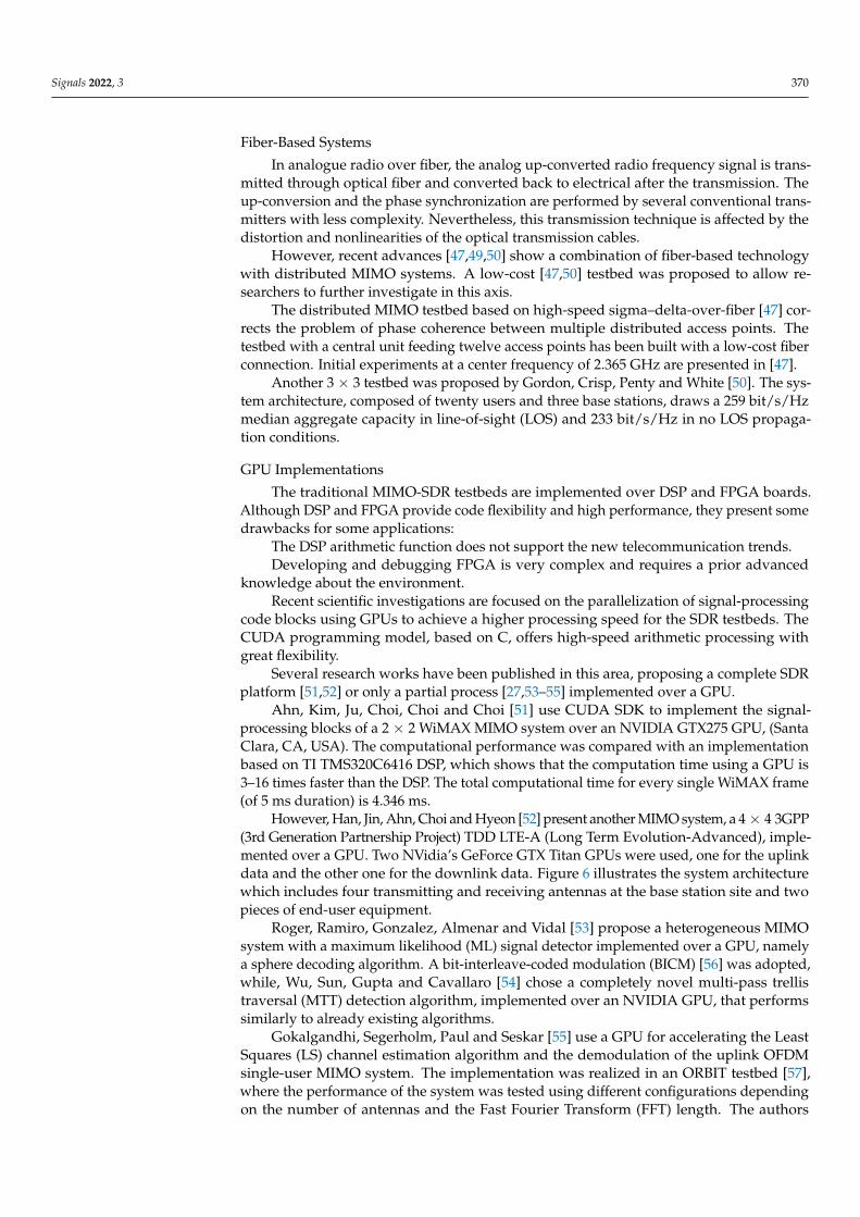
Fiber-Based Systems
In analogue radio over fiber, the analog up-converted radio frequency signal is trans-mitted through optical fiber and converted back to electrical after the transmission. Theup-conversion and the phase synchronization are performed by several conventional trans-mitters with less complexity. Nevertheless, this transmission technique is affected by thedistortion and nonlinearities of the optical transmission cables.
However, recent advances [47,49,50] show a combination of fiber-based technologywith distributed MIMO systems. A low-cost [47,50] testbed was proposed to allow re-searchers to further investigate in this axis.
The distributed MIMO testbed based on high-speed sigma–delta-over-fiber [47] cor-rects the problem of phase coherence between multiple distributed access points. Thetestbed with a central unit feeding twelve access points has been built with a low-cost fiberconnection. Initial experiments at a center frequency of 2.365 GHz are presented in [47].
Another 3 × 3 testbed was proposed by Gordon, Crisp, Penty and White [50]. The sys-tem architecture, composed of twenty users and three base stations, draws a 259 bit/s/Hzmedian aggregate capacity in line-of-sight (LOS) and 233 bit/s/Hz in no LOS propaga-tion conditions.
GPU Implementations
The traditional MIMO-SDR testbeds are implemented over DSP and FPGA boards.Although DSP and FPGA provide code flexibility and high performance, they present somedrawbacks for some applications:
The DSP arithmetic function does not support the new telecommunication trends.Developing and debugging FPGA is very complex and requires a prior advanced
knowledge about the environment.Recent scientific investigations are focused on the parallelization of signal-processing
code blocks using GPUs to achieve a higher processing speed for the SDR testbeds. TheCUDA programming model, based on C, offers high-speed arithmetic processing withgreat flexibility.
Several research works have been published in this area, proposing a complete SDRplatform [51,52] or only a partial process [27,53–55] implemented over a GPU.
Ahn, Kim, Ju, Choi, Choi and Choi [51] use CUDA SDK to implement the signal-processing blocks of a 2 × 2 WiMAX MIMO system over an NVIDIA GTX275 GPU, (SantaClara, CA, USA). The computational performance was compared with an implementationbased on TI TMS320C6416 DSP, which shows that the computation time using a GPU is3–16 times faster than the DSP. The total computational time for every single WiMAX frame(of 5 ms duration) is 4.346 ms.
However, Han, Jin, Ahn, Choi and Hyeon [52] present another MIMO system, a 4 × 4 3GPP(3rd Generation Partnership Project) TDD LTE-A (Long Term Evolution-Advanced), imple-mented over a GPU. Two NVidia’s GeForce GTX Titan GPUs were used, one for the uplinkdata and the other one for the downlink data. Figure 6 illustrates the system architecturewhich includes four transmitting and receiving antennas at the base station site and twopieces of end-user equipment.
Roger, Ramiro, Gonzalez, Almenar and Vidal [53] propose a heterogeneous MIMOsystem with a maximum likelihood (ML) signal detector implemented over a GPU, namelya sphere decoding algorithm. A bit-interleave-coded modulation (BICM) [56] was adopted,while, Wu, Sun, Gupta and Cavallaro [54] chose a completely novel multi-pass trellistraversal (MTT) detection algorithm, implemented over an NVIDIA GPU, that performssimilarly to already existing algorithms.
Gokalgandhi, Segerholm, Paul and Seskar [55] use a GPU for accelerating the LeastSquares (LS) channel estimation algorithm and the demodulation of the uplink OFDMsingle-user MIMO system. The implementation was realized in an ORBIT testbed [57],where the performance of the system was tested using different configurations dependingon the number of antennas and the Fast Fourier Transform (FFT) length. The authors

Signals 2022, 3 371
conclude that the performance offered by a GPU is limited when increasing the number ofantennas and the FFT length. Thus, in a following work they suggested parallelizing theimplementation and using distributed algorithms and a distributed server.
Figure 6. 4 × 4 3GPP TDD LTE-A MIMO system architecture.
Another heterogeneous MIMO system was designed [27] to accelerate the logic treat-ment. This is the mm-wave testbed, which uses open computing language (OpenCL) totransfer data between the FPGA and GPU without involving the CPU.
MIMO Antennas
At this point, the researchers have been focused on designing a new antenna witha maximum gain and lower loss. There were some array antenna prototypes designedto work with base stations [58] and others for the end user’s deployment [59]. The maininnovation concerning this research axis is the concept of reconfigurable antennas [60,61].Reconfigurable antennas could change their operation frequency, in addition to theircharacteristics, to operate within multi-mode services and standards. Thus, they offermultiple advantages such as:
• Operability in multi-band frequencies• Polarization diversity• Low size and cost with high performance.

Signals 2022, 3 372
In fact, increasing the number of active elements used by the antennas allows morereconfigurable features (frequency, bandwidth, . . . ). To obtain this reconfigurable ca-pability, it is necessary to deploy some micro-electronical components such as micro-electromechanical systems (MEMS), varactor, and PIN diodes.
Kamran Shereen, Khattak and Witjaksono [60], Ojaroudi Parchin, Jahanbakhsh Basher-lou, Al-Yasir, Abd-Alhameed, Abdulkhaleq and Noras [61] did an extensive review aboutreconfigurable antennas for 5G applications in general. They cited and analyzed severalprototypes recommended for MIMO and cognitive radio systems [62–66].
3.2. MIMO-SDR Waveforms3.2.1. MIMO Waveforms Analysis
The waveforms implemented within MIMO systems could be coarsely classifiedinto two categories: single-carrier waveforms and multi-carrier waveforms. In addition,multi-carrier waveforms are divided into two subgroups: orthogonal and non-orthogonalones. Table 3 regroups the waveform classification with the relevant references. The tablesummarizes the main advantages and drawbacks of every waveform when deployed withMIMO systems.
Table 3. MIMO waveforms classification: single-carrier and multi-carrier spectrum access techniques.
WaveformReference Advantages/Disadvantages/Summaries
Name Acronym
Single-Carrier
Single-carrier QAM SC-QAM [67]- Even though it requires very low computational
resources, it is not really adapted to MIMO systems- Less flexible in spectral allocation
Single-carriertransmission withfrequency domain
equalization
SC-FDE [68–70]
Considered as a direct alternative to OFDM as it overcomesthe drawbacks presented by this technique. However, itdoes not offer the same flexibility given by OFDMconcerning the management of the bandwidth and theenergy resources.
Single-carrier frequencydivision multiplexing SC-FDM [71,72]
SC-FDM has a low Peak-to-Average Power Ratio (PAPR)compared to OFDM. However, it suffers from noiseenhancement [72,73] phenomena.
Single-carrier FDP SC-FDP [70,74,75]SC-FDP has lower PAPR in comparison with OFDM for alow number of end users. However, with a higher numberof end-users SC-FPD performs the same as OFDM [70].
Single-carrier frequencydivision multiple access SC-FDMA [76,77]
Presents some disadvantages compared to OFDM:
- As the data on each frequency are not orthogonal,the channel estimation using pilots is complex.
- Deploying a non-linear detection algorithm isvery complex.
1. In an outdoor environment, OFDM performs betterthan SC-FDMA.
Multi-Carrier Orthogonal
Orthogonal frequencydivision multiplexing OFDM [78]
This waveform has some drawbacks:
- High PAPR.- Intolerance to the nonlinearities of the
power amplifiers.- High sensitivity to carrier frequency offsets and
transmitted signal fluctuations.
orthogonal frequencydivision multiple access OFDMA [76,77] - higher spectral efficiency for MIMO systems.
- Inter-symbol interference (ISI) does not exist.
Rate-splittingmultiple access RSMA [79] RSMA is a robust technique that allows the deploying of
more powerful coding approaches [80].
Multi-carrier codedivision multiple access
MC-CDMAor OFDM-
CDM[81]
- high presence of PAPR- Improves OFDM but introduces some other
phenomena: bit error rate (BER) degradation andapparition of out-of-band interference (OBI)

Signals 2022, 3 373
Table 3. Cont.
WaveformReference Advantages/Disadvantages/Summaries
Name Acronym
Non-Orthogonal
Sparse codemultiple access SCMA [82]
- For small number of end-users, SCMAs have alower complexity.
- Higher PAPR compared with SC-RSMA.- Offers a very low density spreading, requires
synchronous multiplexing and iterativejoint detection.
- SCMA does take advantage of the fully availablediversity; it uses only a portion of thetime/frequency slots.
- For end users deploying different spreading factors,SCMA is not a good candidate.
Filter BankMulti-Carrier FBMC [83]
- It is an OFDM evolution.- The existing research papers show that it is poorly
compatible with MIMO systems [84].- It is not an attractive candidate for 5G systems.
Space DivisionMultiple Access SDMA [85] - High overloading factor.
- Robust blind detection.
Multi-UserShared Access MUSA [86] - Higher PAPR
Nonorthogonalmultiple access NOMA [87]
- Users are superimposed in the spectral domain,they could share the same frequency bin in the sametime instance.
As OFDM is a strong candidate for fifth-generation (5G) telecommunication sys-tems [80] and it is the most popular waveform used for MIMO systems, an additionalOFDM derivative waveform will be introduced in the next section.
However, the OFDM-MIMO system model is introduced in detail in the follow-ing. The theoretical foundation corresponding to every waveform is described in theattached references.
This section may be divided by subheadings. It should provide a concise and precisedescription of the experimental results and their interpretation, as well as the experimentalconclusions that can be drawn.
3.2.2. OFDM/Cyclic Prefix OFDM (CP-OFDM) Theory Aspects
The OFDM transmitter scheme (please refer to Figure 7) is composed of several signal-processing blocks: inverse fast Fourier transform (IFFT) processing, cyclic prefix (CP)insertion, and spectrum enhancement. Serial to parallel block converts several consecutivesbits to parallel streams with a low bit rate. The modulation (or symbol mapping) isconducted with QAM, QPSK, or Binary Phase Shift Keying (BPSK). In the receiver side, wehave inverse operations to decapsulate the signal, including fast Fourier transform (FFT)processing and cyclic prefix removal. Additional processing is required to estimate thechannel effect and to allow a synchronized communication between the transmitter andthe receiver. The cyclic prefix insertion and the removal blocks are more appropriate to thecyclic prefix OFDM (CP-OFDM) scheme. Additionally, the filtering block in the transmitterand receiver parts exist in the filtered OFDM (F-OFDM) version.

Signals 2022, 3 374
Figure 7. OFDM transceiver: firstly, the serial to parallel (S/P) converter splits the given data toseveral parallel streams which are converted to symbols through the mapping block. Secondly,the output of the IFFT block, after parallel to serial (P/S) conversion, is given to the next block forinsertion of the CP. After the spectrum shaping process, the data are converted to analogue signalsto be transmitted through the Tx antenna. In the receiver side, other filtering and S/P conversionprocesses are performed, and the signal is converted to digital data (symbols). Afterwards, the CPneeds to be removed from the symbols, and an FFT is performed. The channel estimation is the mostimportant block in the receiver. The given output data of this block are given to the equalizer tocorrect the channel effect. Finally, after P/S conversion, the symbols are de-mapped to bits. The CPinsertion and removal blocs are used with cyclic prefix OFDM (CP-OFDM), which widely reducesthe ISIs.
Let us consider a symbol to transmit:
sT = [s0 s1 . . . sL−1] (7)
L is the size of the symbol s.Considering the CP, the symbol is presented by the next formula:
sT =[sL−Lg . . . sL−1 s0 s1 . . . sL−1
](8)
Lg is the number of CP samples.We assume that the channel is time invariant with N taps and an impulse response
given by:cT = [c0 c1 . . . cN−1] (9)
For single-carrier systems, the received signal is obtained through a simple convolutionof the channel impulse response with the initial symbol. Nevertheless, for CP-OFDM

Signals 2022, 3 375
systems, a circular convolution is performed. Therefore, the received signal y, consideringR < Lg, will be expressed as:
y0y1.........
yL−1
=
c0 0 · · · 0 cN−1 · · · c1...
. . . . . . . . . . . ....
.... . . . . . . . . cN−1
cN−1. . . . . . 0
0. . . . . . . . .
......
. . . . . . . . . 00 · · · 0 cN−1 · · · · · · c0
s0.........
sL−1
+ η = Fs + η (10)
η refers to the noise term related to the channel.Otherwise, if R > Lg, some Inter-Symbol Interferences (ISIs) appear.The matrix F can be diagonalized by Fourier transform:
F = E−1DE
D =
D0 0 · · · 0
D1 · · · 0...
. . ....
0 · · · 0 DN−1
(11)
where E and E−1 are the FFT and IFFT matrices, respectively.
3.2.3. MIMO-OFDM Variants
There are five (principally four) OFDM variants tested within MIMO systems, assummarized in Table 4. The most important, drawing real improvement with MIMOtechnology, are CP-OFDM, UF-OFDM, GFDM, and F-OFDM. Nevertheless, CP-OFDM-WOLA is cited by several researchers as a good candidate to work with MIMO systems.Instead of using filters, as with the normal OFDM scheme, WOLA-OFDM uses extensionand windowing techniques to reduce OOB emissions [88,89]. In addition, the classic FBMCtechnique has been announced as being incompatible with MIMO systems [84] as it makesthe implementation of traditional coding and channel estimation algorithms very difficult.However, the MIMO FBMC-OQAM scheme has attracted a lot of researchers [90].
Table 4. MIMO-OFDM variants.
OFDM Variants
CP-OFDM Cyclic prefix OFDM [91]UF-OFDM or UFMC Universal filtered OFDM or universal filtered multi-carrier [83,91,92]CP-OFDM-WOLA Weighted overlap and add CP-OFDM [88,89] 1
GFDM Generalized OFDM [93,94]F-OFDM Filtered OFDM [95]
FBMC Filter-bank multi-carrier [83,96]1 WOLA-OFDM was analyzed by several researchers as being a good candidate that will perform very well withMIMO systems, but to the best of our knowledge, there is no experimental study which proves it.
Figure 7 explains very clearly the additional blocks needed to implement CP-OFDMand F-OFDM as well. Nonetheless, a brief introduction to UF-OFDM, GFDM, and FBMC-OQAM is given in the following.
• GFDM

Signals 2022, 3 376
GFDM deploys a circular pulse shaping to diminish the inter-carrier interference (ICI)phenomena. In comparison with OFDM, GFDM is more flexible to carrier frequency offsetand time synchronization-induced errors [97].
The baseband scheme of a MIMO-GFDM transceiver [94,97] is given in Figure 8.
Figure 8. GFDM transceiver: the GFDM modulator consists of two stages, pulse shaping andsubcarrier up-conversion. In the demodulator, those operations are inversed: subcarrier down-conversion and filtering.
The mapped symbols (with QAM, QPSK, or BPSK) are converted to parallel sub-streams for padding K subcarriers with M sub-symbols.
The parallel streams are up-sampled, with a sampling factor N, to correct the sub-symbol position in the block [97]. Afterwards, a circular convolution with a Tx filter isperformed to exclude replicated samples; so, the subcarriers could be shifted to their centerfrequencies afterwards. Only one CP is inserted for all the concatenated M sub-symbols. Inthe receiver side, the CP is cut from the data, in addition to the other reversed operationsperformed to retrieve the final data. The equalization is for channel effect correction. TheGFDM still suffers from a few drawbacks, especially a higher out-of-band (OOB) emissionproblem and high-complexity computation.

Signals 2022, 3 377
• UF-OFDM
UF-OFDM is a promising waveform which uses linear filters and eliminates the cyclicprefix. The baseband structure of the transceiver [97] is presented in Figure 9. The mappedsymbols are converted to parallel streams. After computing an M-point IFFT over eachsub-band, a band filter is applied. In fact, the use of the Dolph–Chebyshev bandpassfilter (BPF) helps to tackle the OOB emissions [91,97]. Next, the filtered sub-bands aresuperposed and sent through the channel.
Signals 2022, 3, FOR PEER REVIEW 19
over each sub-band, a band filter is applied. In fact, the use of the Dolph–Chebyshev bandpass filter (BPF) helps to tackle the OOB emissions [91,97]. Next, the filtered sub-bands are superposed and sent through the channel.
Figure 9. UF-OFDM transceiver.
A zero-padding process is performed from the receiver side. In fact, every symbol is padded with N − L zeros, where L is the BPF filter (in the transmitter side) length. Afterwards, the signals are demodulated by 2M-point FFT. The demodulated signals, excluding the padded zeros, are given to the equalizer to eliminate the channel distortions. Finally, the symbols are de-mapped to bits.
UF-OFDM outperforms OFDM in terms of ICI and ISI reduction, PAPR, and spectral efficiency. • FBMC-OQAM
The original version of FBMC does not deploy any CP and uses a pulse-shaping filter. Therefore, it offers lower spectral sidelobes and computation latency, in addition to robustness to multipaths in high-loss environments.
FBMC-OQAM uses QAM mapping, with in-phase and quadrature components that are diphase in time by half the symbol period, and a well-designed pulse-shape filtering to satisfy the orthogonality propriety. Hence, the interferences between the adjacent bands do not affect the quality of transmission for this scheme. In fact, the received data do not suffer from either ISI or ICI due to the orthogonality condition imposed between the adjacent bands.
The diagram of an FBMC-OQAM baseband transceiver is depicted in Figure 10. sk(m) represents the transmitted symbol with the frequency and time indexes k and m, respectively. xk(2 m) and xk(2 m + 1) are gathered by calculating the real and imaginary components of the symbol resulting from the mapping stage, respectively. g(t) is the time response of the symmetrical pulse-shaping filter [90].
Serial to Parallel
Converter
FDE De-mapping (QAM/QPSK)
Channel
Data Mapping and
Coding (QAM/QPSK)
M-Point IFFT
BPF
Parallel to Serial Converter
...
...
Parallel to Serial Converter 2M-
Point FFT
Zero padding
FDE frequency-domain equalizer BPF Band pass filetring
Figure 9. UF-OFDM transceiver.
A zero-padding process is performed from the receiver side. In fact, every symbolis padded with N − L zeros, where L is the BPF filter (in the transmitter side) length.Afterwards, the signals are demodulated by 2M-point FFT. The demodulated signals,excluding the padded zeros, are given to the equalizer to eliminate the channel distortions.Finally, the symbols are de-mapped to bits.
UF-OFDM outperforms OFDM in terms of ICI and ISI reduction, PAPR, and spec-tral efficiency.
• FBMC-OQAM
The original version of FBMC does not deploy any CP and uses a pulse-shapingfilter. Therefore, it offers lower spectral sidelobes and computation latency, in addition torobustness to multipaths in high-loss environments.
FBMC-OQAM uses QAM mapping, with in-phase and quadrature components thatare diphase in time by half the symbol period, and a well-designed pulse-shape filtering tosatisfy the orthogonality propriety. Hence, the interferences between the adjacent bandsdo not affect the quality of transmission for this scheme. In fact, the received data donot suffer from either ISI or ICI due to the orthogonality condition imposed between theadjacent bands.
The diagram of an FBMC-OQAM baseband transceiver is depicted in Figure 10.sk(m) represents the transmitted symbol with the frequency and time indexes k and m,respectively. xk(2 m) and xk(2 m + 1) are gathered by calculating the real and imaginarycomponents of the symbol resulting from the mapping stage, respectively. g(t) is the timeresponse of the symmetrical pulse-shaping filter [90].

Signals 2022, 3 378
Figure 10. FBMC-OQAM transceiver.
3.2.4. MIMO-OFDM Variants Enhancement Studies
In addition to the existing OFDM waveform variants described before, several authorshave suggested additional enhancements to those structures.
In this paragraph, we are going to give a brief insight into the most significant ad-ditions to the literature. Table 5 regroups those studies, with reference to the base wave-form scheme.
Table 5. MIMO-OFDM variants enhanced schemes.
Enhancement ofStudy OFDM CP-OFDM UFMC GFDM F-OFDM FBMC
Chang and Ueng [98] XSharief and Sairam [99] XSingh, et al. [100] XZakaria and Le Ruyet [101] XZhao, et al. [102] XYu, et al. [103] X 1
Jin, et al. [104] XAminjavaheri, et al. [105] XPereira, et al. [106] X
1 It is theoretically proven that it is compatible with MIMO systems, but not tested experimentally.
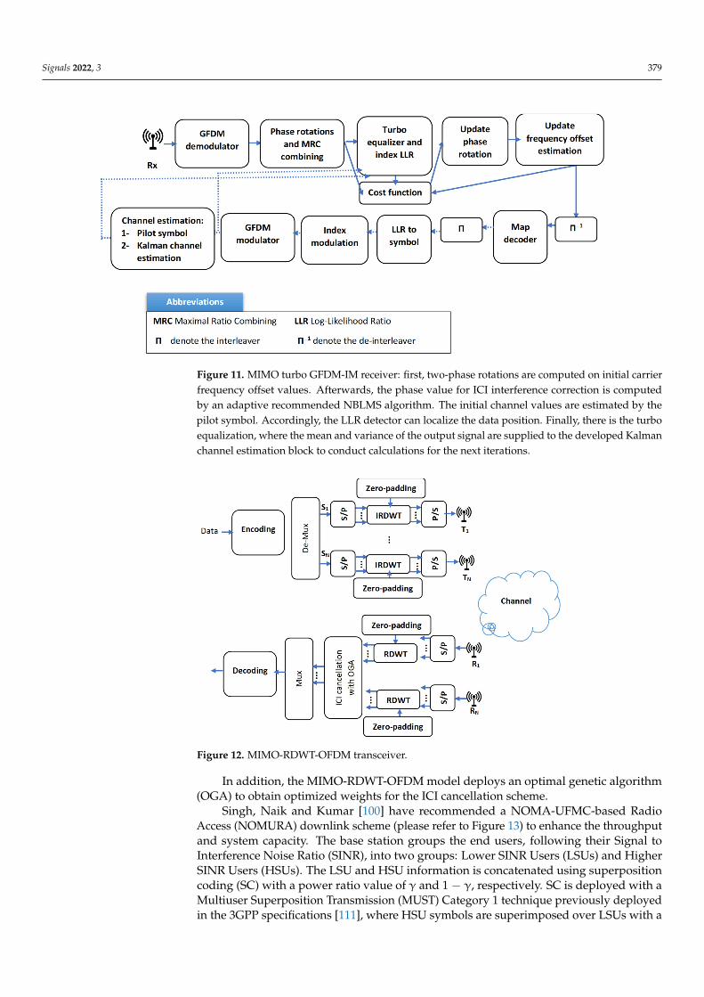
Chang and Ueng [98] recommend a GFDM receiver scheme based on index modulation(IM) [107], considering a fading channel variable in time. The designed architecture (pleaserefer to Figure 11) overcomes the defects introduced by shaping filters used with GFDM,namely self-created inter-carrier interference (ICI) and ISI as well. It deploys two-phaserotations to work for multipath transmission in fast-fading environments. The optimalphase rotations are obtained by maximizing the carrier-to-interference ratio (CIR). In fact,the authors suggested a new algorithm that uses the adaptive normalized block least-mean-squared (NBLMS) method [108], which allows the avoidance of the feedback of the carrierfrequency offset. The Kalman algorithm was chosen to model the time variation of thechannel using the pilot-symbol-aided estimation technique [109], combined with the turbominimum mean square error (MMSE) equalizer [110]. In fact, the turbo equalizer deploysan iterative scheme to update the Kalman channel estimator, equalizer, and decoder blocks,given values until the convergence is achieved.
The log-likelihood ratio (LLR) is used to determine the current active carrier. It wasproven that the current receiver scheme could reduce the decoding process for the currentactive subcarrier.
Sharief and Sairam [99] have suggested a new redundant discrete wavelet-basedMIMO-OFDM (MIMO-RDWT-OFDM) framework, depicted in Figure 12. The utilizationof the new introduced redundant discrete wavelet transform, which does not have thedown-sampling step in the decomposition tree, widely improves the spectral efficiencyof the transceiver, and it could be deployed in Additive White Gaussian Noise (AWGN)channels such as the Rayleigh fading model as it is more robust for noise [99].
Signals 2022, 3 379
Figure 11. MIMO turbo GFDM-IM receiver: first, two-phase rotations are computed on initial carrierfrequency offset values. Afterwards, the phase value for ICI interference correction is computedby an adaptive recommended NBLMS algorithm. The initial channel values are estimated by thepilot symbol. Accordingly, the LLR detector can localize the data position. Finally, there is the turboequalization, where the mean and variance of the output signal are supplied to the developed Kalmanchannel estimation block to conduct calculations for the next iterations.
Figure 12. MIMO-RDWT-OFDM transceiver.
In addition, the MIMO-RDWT-OFDM model deploys an optimal genetic algorithm(OGA) to obtain optimized weights for the ICI cancellation scheme.
Singh, Naik and Kumar [100] have recommended a NOMA-UFMC-based RadioAccess (NOMURA) downlink scheme (please refer to Figure 13) to enhance the throughputand system capacity. The base station groups the end users, following their Signal toInterference Noise Ratio (SINR), into two groups: Lower SINR Users (LSUs) and HigherSINR Users (HSUs). The LSU and HSU information is concatenated using superpositioncoding (SC) with a power ratio value of γ and 1 − γ, respectively. SC is deployed with aMultiuser Superposition Transmission (MUST) Category 1 technique previously deployedin the 3GPP specifications [111], where HSU symbols are superimposed over LSUs with a

Signals 2022, 3 380
non-gray bit-mapping algorithm. Thereafter, UFMC is applied for every sub-band, withspecific filtering parameters according to every user requirement.
Figure 13. MIMO NOMORA system: P/S and S/P are abbreviations for parallel to serial and serialto parallel, respectively. F1, . . . , FB (this refers to the filter used for sub-band B) filter parametersdepend on the users’ requirements.
The recommended transceiver is tested under AWGN as well as Rayleigh fadingenvironments. As described in Figure 13, the zero padding is performed to increase thelength of the transmitted symbols to give them as input to the 2N-point discrete Fouriertransform (DFT) block. A zero-forcing equalization was considered to correct the channeleffect. In the demodulation part, LSUs threaten the HSU user signals as noise to extract theLSU original symbols. However, the HSU signals are reconstructed by demodulating andmodulating the received signals to subsequently reconstruct the LSU signals, which aresubtracted from the received signal to finally obtain the HSU data to be demodulated.
Zakaria and Le Ruyet [101] propose a new FFT-FBMC scheme with less interferenceterms in comparison to the original OFDM algorithm. The FFT-FBMC deploys DFT andCP insertion blocks (with a lower CP length), which make the scheme more complex buthighly compatible with MIMO signal-processing algorithms. The transmission strategyuses guard intervals as well to isolate the adjacent subcarriers. The scheme was tested withmaximum likelihood detection and Alamouti space–time coding algorithms.
Zhao, Gong and Schellmann [102] have introduced a novel FBMC-OQAM schemeto minimize inter-block interference by performing a single-band (SSB) filtering on theedge subcarriers of the resource blocks. This filtering procedure helps to preserve theorthogonality between the sub-symbols within the same block and allows the transceiverto reach the complex field orthogonality at the edges without the need to insert any guardintervals. In this context, a novel resource mapping scheme was chosen, which is shown inFigure 14. This scheme allocates Sc 0 (referring to the SSB filtered edge carrier) as well tothe two initial resources in an alternating way.

Signals 2022, 3 381
Figure 14. The resource mapping scheme.
Another enhanced FBMC based waveform, proposed by Jin, Hu, Huang, Li, Zhangand Ma [104], introduces a new conjugated FBMC-OQAM scheme. The authors takeadvantage of the fact that the pulse-shaping filter of the FBMC-OQAM systems exhibitsodd symmetry, and the interferences that destruct the orthogonality (the intrinsic inter-symbol and the inter-carrier interferences) are strictly related to the neighboring symbols.Therefore, the idea was to divide the time-frequency resources into two parts, allowingthe transmission of the original symbols and the corresponding conjugated version of theoriginal ones. A unique signal-processing procedure is used to combine two convenientlyseparated sub-blocks. The recommended FBMC-OQAM system achieves an optimizingdiversity gain.
Yu, Guanghui, Xiao, Zhen, Jun and Bo [103] were among the multiple other authorsthat theoretically proved that the filter bank OFDM (FB-OFDM) was compatible withMIMO systems. The baseband diagram of the transceiver is presented in Figure 15. Themain difference between this scheme and the one of the traditional OFDM technique is thefiltering part.
Figure 15. FB-OFDM transceiver.
Aminjavaheri, Farhang, Rezazadehreyhani, Doyle and Farhang-Boroujeny [105] pro-posed to remove the CP from the OFDM in massive MIMO systems. In addition, a time-reversal (TR) technique was used to resolve the saturation problems with the conventionalfrequency-domain-combining techniques: combining zero forcing and minimum meansquare error detectors. The designated architecture achieves high spectral efficiency inrealistic conditions.
Pereira, Bento, Gomes, Dinis and Silva [106] introduced the Time-Interleaved BlockWindowed Burst-OFDM (TIBWB-OFDM) waveform technique, which is easily applied toMIMO, as presented in Figure 16. The idea was to cluster the data into windowed (with atime-square root-raised cosine filter) short OFDM blocks, zero padded (ZP). The small sizeFFTs and ZP integrated blocks widely improve the power efficiency and reduce the PAPR.

Signals 2022, 3 382
Figure 16. TIBWB-OFDM transceiver.
3.3. MIMO-OFDM Block Enhancements
In the literature, interesting studies were presented to enhance the MIMO-OFDMtransceiver performance. Notably, the studies related to the channel estimation and equal-ization process. In the following, the relative studies and notions will be further expanded.
3.3.1. Channel Estimation
The MIMO-OFDM channel estimation schemes in the literature could fall under threemain classes: pilot-aided (or training-based), blind techniques and semi-blind ones, anddecision-directed channel estimation.
Quite a few innovative works have been found in the literature with regard to pilot-aided techniques, due to the induced processing overload of the pilots’ data.
Table 6 gives a vision about the general classification of channel estimation for MIMO-OFDM wireless communication systems, in addition to the corresponding study referencesfor every algorithm type. In the following, those studies will be more detailed in theproper context.
Table 6. MIMO-OFDM channel estimation algorithms classification.
ClassificationPilot-Aided (orTraining-Based)
Blind [112] and Semi-Blind Decision-Directed
Statistical Methods DeterministicMethods Hard Soft
2nd Order High Order
References [113–124] [125–127] [128,129] [130–133] [134] [135–139]
• Pilot-aided channel estimation algorithms
The pilot-assisted channel estimation or training-based technique inserts trainingpilots, which are well known by the receiver, to the transmitted sequence of symbols.Therefore, the receiver could extract CSI information, which is gathered by an interpolationbetween the different CSI values already extracted from the pilot sequences.
In fact, the pilots’ arrangement could be in three types: comb type [113], blocktype [113,114], or 2D-grid type [118]. Figure 17 gives a better vision of the three situations.

Signals 2022, 3 383
Figure 17. Pilot arrangement possible situations: (a) block type; (b) comb type; (c) 2D-grid type.
The shaded circles represent pilot symbols, whereas the unshaded ones represent thesymbols to be transmitted. The horizontal axis is the time direction, and the vertical one isthe frequency direction that represents the OFDM subcarriers.
The general scheme of a pilot-aided channel estimator (please refer to Figure 18) iscomposed of an LS/LMMSE estimator block, a frequency, and a time interpolator block,respectively, and a denoising and truncation block. The LS/LMMSE block calculates thechannel frequency response using the received pilot symbols. The next step is to convert thisresponse to the time domain. Afterwards, a denoising and truncation process is performed.
Figure 18. Pilot-based channel estimation scheme.
Some of the used frequency interpolators in the literature are: linear, second order,cubic spline, time domain-based, low-pass [140]; and DFT-based interpolators [117,118].
The block-type estimation is performed in the time domain, while for the comb type itis performed in the frequency domain.
The most adopted algorithms for channel estimation using the block-type pilot are:least squares [113,121,122] and Linearity Minimum Mean Squared Error (LMMSE) [139].
In [113], an LS channel estimator was investigated based on the block-type pilotstructure and the comb-type pilot structure, with average MSE lower bounds.
In [114], a reduced-based LS estimator was designed, accepting the assumption thatthe channel was quasi-static over every two OFDM symbols, and their neighboring pilotswere consecutively grouped as an equispaced cluster. The pilot is inserted into a designatedblock at each Tx antenna, i.e., it is sent periodically in the time domain. The channelresponse matrices are decoupled for every Tx antenna. Therefore, the MIMO channelestimation problem is formulated as a simple Single Input Output (SISO) correspondingchannel estimator.
In [115], a channel estimator based on MMSE, which requires the calculation of theinverse of the channel autocorrelation matrix, was proposed. Hence, a singular valuedecomposition was used to reduce the induced complexity. The nominated comb-typepilot-based technique was used within a space–time block coding (STBC).
Conventionally, the comb-type pilot is the most used for the relatively small MIMO–OFDM architectures [116]. However, with more complex architectures, the amount ofoverhead increase and the choice of pilot sequence become a more important point whenavoiding the pilot contamination problem (the case of using the same pilot sequence). Thus,

Signals 2022, 3 384
several authors [117,119] have opted to use the Zadoff Chu (or generalized Chirp-like)sequences, due to their orthogonality characteristics.
In [117], the estimation was performed using a DFT-based method in the time domain;the interpolation step was completely omitted. Zheng, Su and Wang [117] took advantageof the fact that a delay in the time domain is transposed as a phase shift in the frequencydomain. Therefore, they inserted the pilots in the frequency domain, while the estimationwas performed in the time domain.
In [118], a 2D grid-type scheme with a DFT-based time interpolator block was chosenfor a massive MIMO system, due to its lower complexity. The nominated block incorporatesa 2-point DFT (instead of the N-point DFT in conventional algorithm) process to optimizethe use of the storage resources. The algorithm was simulated in various Rayleigh fadingchannel conditions with the universal threshold truncation technique [141].
Another training scheme where the pilots are spread in both time and frequencydirections was designated in [119]. The novel time-frequency training OFDM scheme(TFT-OFDM) performs, jointly, a time estimation and an N-point DFT-based frequencyestimation. The two estimators are unified under the same framework.
However, in [120], the authors investigate a different pilot-symbol scheme whichadopts an ML estimator followed by a Wiener filtering approach for an LTE MIMO-OFDMsystem. The conducted study proved that a denser pilot combined with a partial knowl-edge of some statistics of the channel could attenuate the BER affected by interpolationerror accumulation.
Hlaing, Al-Dhahir and Yinghui [121] consider a robust least-squares estimation fora channel with frequency offset and phase noise, while Hardjawana, Li, Vucetic, Li andYang [122] choose a novel receiver structure based on pilot symbols and an iterative soft-estimate. In [122], the estimator is based on an LS time-domain interpolator. The softestimate was realized through an improved maximum a posteriori (MAP) decoder.
Despite the traditional LS- and LMMSE-based estimators that have a relatively limitedperformance with the existence of strong interferences, novel innovative approaches basedon machine learning are being introduced [123,124,142].
A sparse Bayesian learning-based estimator was designated in an orthogonal space–time block coded MIMO-OFDM system for an approximatively sparse channel type [123].This technique updates the channel coefficients within a maximization formulation basedon an ML algorithm for the estimation of the hyper parameters of the channel. Moreover,in [124] a pilot selection idea was implemented using a cat swarm optimization to enhancethe channel estimation process.
More recently, the need to provide full secrecy in sensitive data applications hasspurred research in physical layer secure communications. The usage of MIMO by increas-ing the number of parallel and independent channels in a rich scattering environment hasbeen recognized to be a tool to increase the uncertainty about the channel and therefore in-crease the equivocation rate at an illegitimate receiver (e.g., [143,144] and references therein).
• Blind and semi-blind channel estimation algorithms
The blind channel estimation algorithms rely on statistical proprieties, do not needprior knowledge about the transmitted signal, and do not require inserting pilots or trainingsymbols at the transmitter level, thus allowing the sending of more data and the attain-ment of higher spectral efficiency. However, the semi-blind techniques use a part of theknowledge of the signal in addition to some statistical characteristics. Under this category,there are two sub-categories: statistical methods and deterministic techniques.
For statistical techniques, the cyclic statistic properties of the signals are requested inthe receiver side, although the deterministic techniques need both the coefficients and thereceived signal for estimating the channel matrix.
The statistical techniques are second- [125–127] or higher-order statistics (HOS) [128,129].In [125], a blind scheme for a zero-padding MIMO-OFDM system, based on the
covariance statistics, was presented. The channel matrix was obtained by resolving anequation series resulting from the covariance matrix of the received signal by exploiting the

Signals 2022, 3 385
block Toeplitz structure. The linear equations were reformulated into a set of decoupledgroups. Then, the channel matrix was calculated within an eigen-decomposition of theouter product matrix.
In [126], a semi-blind scheme based on circular precoding was suggested, where theautocorrelation matrix of the received data engenders a set of mathematical equations inrelation with the outer product of the channel matrix and the coefficients induced by theprecoder. Some information about channel matrices was extracted from those equations,thus a Hermitian matrix was created within it. The corresponding positive eigenvalues andeigenvectors of this Hermitian matrix allow, finally, the gathering of the channel matrix.
However, Wan, Zhu and Swamy [127] tested an idea to cancel the signal perturbationof the second-order statistics estimators. First, it was necessary to analyze the correlationmatrix of the received data. Afterwards, a novel way to transmit the data, considering theperturbation that could be cancelled, was applied. Moreover, the authors proved that byusing a few specific additional slots the performance of this technique could achieve anideal case.
In [128], a blind iterative hybrid independent component analysis (HICA) estimationschema is presented. Initially, the authors apply the pulse-shaping method with a squareroot-raised cosine filter to reduce the ISIs. Next, the signals in the receiver are identifiedby determining the separation matrix. The estimated signal order is different for everyHICA iteration because the algorithm is randomly initialized. Hence, only the informationthat will appear repetitively in every iteration will be significant. The estimated desiredsignal is selected based on HOS from common signals resulting from different iterationsof the HICA algorithm. Despite this, Peken, Vanhoy and Bose [129] introduced anotherless complex adaptive independent component analysis-based scheme, applied to massiveMIMO. The algorithm is an improvement of the work carried out in [145].
To resume, the performance of statistical algorithms is usually influenced by the finitedata effect. The deterministic algorithms [130–133,139,146] are the more complex ones, butthey converge faster.
In [130], a compressed sensing-based algorithm was suggested, where only a deter-ministic subset of the index is selected to place the pilots in the data to be transmitted.Hence, this leads to some new measurement matrices and a new reconstruction algorithm.
However, in [131] a space-alternating generalized expectation-maximization (SAGE)-related scheme for STBC is divulged. The channel coefficients are estimated at pilotpositions by a decomposition of the superimposed received signals, while the rest ofthe coefficients are calculated by Wiener interpolation. In [132], it is another semi-blindSAGE-based algorithm that contributes to a periodic update of the pilot-related MMSEestimate. Conventional estimators request the insertion of more pilots and more knowledgeabout large-scale fading coefficients to attain the desired performance, while this algorithmdeploys the data symbols to estimate the missing information.
The framework exposed in [133] is a special case for channels with faster time-varyingcharacteristics. It is an optimized semi-blind sparse estimator with a cost function estimatedby an enhanced differential evolution algorithm. The semi-blind estimation was performedby LMMSE and LS. Afterwards, the enhanced differential evolution algorithm was adoptedto diminish the cost function and further optimize the estimator.
• Decision-directed channel estimation algorithms
For these techniques, the detected symbols are deployed in addition to relatively fewpilots for estimating the channel. This kind of scheme gives more reliable results than thepilot-assisted techniques because there are no transmission errors. The decision-directedtechniques first necessitate an initial estimation of the channel transfer function, calculatedstaring from the current received and detected data. This estimation is used afterwardsas an a priori channel estimate during the treatment of the next symbols of the incomingtime slot.
Those techniques are in two groups: soft and hard decision-directed methods.

Signals 2022, 3 386
In [134], a joint pilot-aided and hard blind decision-directed channel estimation (PA-DDCE) scheme is explained. The authors gather the initial channel estimate using theconventional LS algorithm. Then, this estimate is deployed to detect the next data symbolsituated between any two adjacent pilot sub-carriers. Subsequently, those symbols becomelike additional pilot symbols that are used to complete the estimation of the missing channelcoefficients on the frequency band.
However, Park, Choi, Lee and Shim [135], Park, Shim and Choi [136] have a softdecision-directed strategy, drawing an interesting performance, which uses an iterativedetector and decoder to optimize the estimation process. The algorithm (partially demon-strated in Figure 19) utilizes virtual pilots as well as pilots for the channel re-estimation. Inthe beginning, posteriori LLRs are built by an addition of the extrinsic LLRs resulting fromthe MIMO detector and the prior LLRs resulting from the decoder.
Figure 19. Channel iterative estimation scheme.
Thus, those posteriori LLRs are translated to soft symbols. Afterwards, virtual pilotsare selected from the data available in the current window. In fact, the virtual pilot signalsneed to meet two principal conditions:
First, the magnitude of the posteriori LLRs needs to be high.Second, the channels for the virtual pilots and the pilots need to be highly correlated.However, after gathering those virtual pilots, the channel is re-estimated within the
original pilots. The new estimate is given to the MIMO detection block in the next iteration.In [137], a Kalman-like estimator based on a specific pipelined turbo equalizer logic
was verified (please refer to [137] for further details about the architecture). Before forward-ing the data to the Kalman estimator block, a specific algorithm was used to diminish thedecision error correlation between the different pipeline stages.
Nonetheless, in [138], there is a deep neural network-based approach for the channelestimation of an STBC MIMO system. Two networks are trained to estimate the real andthe imaginary part of the matrix of the fast-varying fading channel.
Finally, in [139], the performances of the LS, MMSE, and SAGE algorithms for adecision-directed estimator are assessed. The performance is improved by substitutingsome of the pilots with data symbols; then, the SAGE technique is used to downslide theloss induced.
3.3.2. Equalization
There are several logics to categorize the equalization algorithms. There are linearand non-linear equalizers. The linear algorithms are less complex than the non-linearones, but they do not take into consideration the additive noise. Zero-forcing (ZF) [147],MMSE [148], and Least Mean Square (LMS) are all linear equalizers. The decision feedbackequalizer (DFE) is a nonlinear equalizer that reduces ICI by an adopted filtering technique.We propose to categorize the existing algorithms as follows:

Signals 2022, 3 387
Type 1: Basic equalization techniques: ZP-, MMSE-, and LMS-based algorithms.Type 2: Specialized techniques to reduce interference: turbo equalization [137,149],
widely used to mitigate interference, is a technique that considers the channel as convolu-tional code and uses turbo decoding algorithms.
Type 3: Blind frequency-domain equalization: deploys a blind channel estimator.A variety of proposed equalization algorithms for MIMO-OFDM systems are classified
in Table 7. Every algorithm is related to its corresponding type, and it is attached with alittle description.
Table 7. MIMO-OFDM equalization algorithm classification.
Type References Year Main Idea Key Algorithms
Type 1 [150] 2019
A symmetric successive over-relaxation (SSOR)method to reduce the complexity of the classical ZFprecoding which uses the channel property ofasymptotical orthogonality to compute the optimalrelaxation parameters.
SSOR technique for ZF
Type 3 [151] 2019
- A supervised learning architecture to predictthe constellation points based on pilot signalswhich constitue training data.
- A new activation function was proposed to beable to use the famous stochastic gradientdescent algorithm for optimization.
Deep neural networkwith gradient descent
algorithm
Type 2 [149] 2019
- The Kalman channel estimation and turboMMSE equalization are used.
- The iterative algorithm repeats the channelestimation, equalization, and decodingoperations until convergence. The feedbackinformation received from the decoder isinjected another time into the equalisationprocess.
Turbo MMSE equalizerwith MAP decoder
Type 1 [148] 2018 Testing MMSE equalizer with a decision-directedchannel estimator in a multipath fading channel MMSE algorithm
Type 2 [152] 2012 Iterative receiver based on equal gain combining(EGC) and maximum ratio combining (MRC) RGC, MRC and LLR
Type 3 [147] 2009
An independent component analysis-basedequalizer: First the received signal is whitened byprincipal component analysis, using JADE togather uncorrelated signals. A phase shifting isperformed as well as a reordering technique.
JADE batch algorithm
Type 1 [147] 2009
Exchanging the order of the processing block:interpolation and the ZF equalizer stage. Thisoperation is performed at each pilot position, thenthe ZF equalizer is interpolated over thewhole grid.
ZF equalization
Type 2 [153] 2009
The oblique projection (OB) with QR-basedfactorization is used to separate the noise from thedata. Afterwards, the resulting matrix is forwardedto the DFE equalizer.
DFE equalizer,associated with the OB
Type 3 [154] 2008 A semi-blind time domain equalization, using second-order statistics and aone-tape equalizer.
Type 2 [155] 2007a DFE equalizer combined with Recursive LeastSquares (RLS) to compute the coefficient of theadaptive filter.
RLS algorithm
Type 1 [156] 2007An MMSE equalizer based on QR factorizationimplemented on FPGA to compute the inverse ofthe filter matrix.
MMSE and QRfactorization

Signals 2022, 3 388
4. Conclusions
The combination of MIMO transmission techniques with the OFDM waveform hasbrought an emerging technology to the wireless telecommunication field. In the last decade,MIMO-OFDM has drawn distinguished advances in terms of hardware and softwareinnovations. Universities and telecommunication leaders have made prominent massiveMIMO architectures operational and accessible for research proposals to further encouragenew additions to the current literature.
We presented an extensive review of MIMO-OFDM, tackling several difficulties toregroup all the important research axes. The most important and recent references were in-cluded to point out the necessary information for the readers without redundancy. Nonethe-less, some recent papers could have been missed as we mainly limited the resources tothree databases: ISI Web of Science, IEEE Xplore, and Google Scholar. Hence, some paperswere automatically excluded from the search, but the papers indexed on those databaseshave more impact on and relevance to the addressed topic. The reported state of the artconcerned three essential points: MIMO hardware/software technology, MIMO waveforms,and MIMO-OFDM channel estimation and equalization.
From the above extensive search, some points can be noticed:
- The part on implementation is more limited to research testbeds that apply traditionalchannel estimation algorithms.
- The most deployed channel estimation algorithms are complex and have a lower levelof mitigation of ICI.
- The equalization algorithms are quite limited in terms of performance.
In the next section, some challenges and research opportunities are highlighted.
4.1. Challenges
The most challenging problem in the MIMO-OFDM system is the elimination of theICI and ISI interferences. One cumbersome solution would be to use a CP-OFDM variant.Nonetheless, with massive MIMO architecture and with some complex signal processingalgorithms (channel estimation, equalization, coding, decoding) the process would causea lot of latency, which would alter the communication with a lot of delays and errors. Infact, when the CP length is less than the channel impulse response, ISI and ICI degrade theperformance of the receiver. The inherent idea is to choose a suitable channel estimator anda key equalization technique to fade away the interference effect.
4.2. Opportunities
There are some worthy ideas that could be exploitable for future research:
- The machine learning algorithm, as well as the empirical mode decomposition-basedmethods, draws interesting results for the channel estimating problem.
- The equalization techniques based on the wavelet decomposition technique are interesting.- OFDM waveform enhanced schema.
Author Contributions: Conceptualization, P.M., A.G. and F.G.; methodology, H.H.; software, H.H.;validation, P.M., A.G. and F.G.; formal analysis, H.H.; investigation, H.H.; resources, P.M. and A.G.;data curation, H.H.; writing—original draft preparation, H.H. and H.F.T.A.; writing—review andediting, H.H., P.M., A.G. and H.F.T.A.; visualization, H.H., P.M. and A.G.; supervision, P.M. andA.G.; project administration, P.M.; funding acquisition, P.M. All authors have read and agreed to thepublished version of the manuscript.
Funding: This work was partially supported by the European Regional Development Fund (FEDER),through the Regional Operational Programme of Centre (CENTRO 2020) of the Portugal 2020 frame-work, through projects SOCA (CENTRO-01-0145-FEDER-000010) and ORCIP (CENTRO-01-0145-FEDER-022141). Fernando P. Guiomar acknowledges a fellowship from “la Caixa” Foundation (ID100010434), code LCF/BQ/PR20/11770015. Houda Harkat acknowledges the financial support of theProgrammatic Financing of the CTS R&D Unit (UIDP/00066/2020).

Signals 2022, 3 389
Institutional Review Board Statement: Not applicable.
Informed Consent Statement: Not applicable.
Data Availability Statement: Not applicable.
Acknowledgments: We would like to thank the editor and the reviewers for their comments whichhelped us improve the paper.
Conflicts of Interest: The authors declare no conflict of interest.
References1. Garcıa-Naya, J.A.; González-López, M.; Castedo, L. An overview of MIMO testbed technology. In Proceedings of the 4th
International Symposium on Image and Video Communications over Fixed and Mobile Networks (ISIVC’08), Bilbao, Spain,9–11 July 2008.
2. Delson, T.R.; Jose, I. A Survey on 5G Standards, Specifications and Massive MIMO Testbed Including Transceiver Design ModelsUsing QAM Modulation Schemes. In Proceedings of the 2019 International Conference on Data Science and Communication(IconDSC), Bangalore, India, 1–2 March 2019; IEEE: Piscataway, NJ, USA, 2019; pp. 1–7.
3. Shafi, M.; Molisch, A.F.; Smith, P.J.; Haustein, T.; Zhu, P.; Silva, P.D.; Tufvesson, F.; Benjebbour, A.; Wunder, G. 5G: A TutorialOverview of Standards, Trials, Challenges, Deployment, and Practice. IEEE J. Sel. Areas Commun. 2017, 35, 1201–1221. [CrossRef]
4. Banelli, P.; Buzzi, S.; Colavolpe, G.; Modenini, A.; Rusek, F.; Ugolini, A. Modulation Formats and Waveforms for 5G Networks:Who Will Be the Heir of OFDM?: An overview of alternative modulation schemes for improved spectral efficiency. IEEE SignalProcess. Mag. 2014, 31, 80–93. [CrossRef]
5. Wang, C.; Haider, F.; Gao, X.; You, X.; Yang, Y.; Yuan, D.; Aggoune, H.M.; Haas, H.; Fletcher, S.; Hepsaydir, E. Cellular architectureand key technologies for 5G wireless communication networks. IEEE Commun. Mag. 2014, 52, 122–130. [CrossRef]
6. Amin, M.R.; Trapasiya, S.D. Space Time Coding Scheme for MIMO system-Literature Survey. Procedia Eng. 2012, 38, 3509–3517.[CrossRef]
7. Chen, S.; Zhang, J.; Zhang, J.; Björnson, E.; Ai, B. A survey on user-centric cell-free massive MIMO systems. Digit. Commun. Netw.2021, in press. [CrossRef]
8. Mokhtari, Z.; Sabbaghian, M.; Dinis, R. A Survey on Massive MIMO Systems in Presence of Channel and Hardware Impairments.Sensors 2019, 19, 164. [CrossRef]
9. Ijiga, O.E.; Ogundile, O.O.; Familua, A.D.; Versfeld, D.J. Review of channel estimation for candidate waveforms of next generationnetworks. Electronics 2019, 8, 956. [CrossRef]
10. Wen, F.; Wymeersch, H.; Peng, B.; Tay, W.P.; So, H.C.; Yang, D. A survey on 5G massive MIMO localization. Digit. Signal Process.2019, 94, 21–28. [CrossRef]
11. Zheng, K.; Zhao, L.; Mei, J.; Shao, B.; Xiang, W.; Hanzo, L. Survey of Large-Scale MIMO Systems. IEEE Commun. Surv. Tutor. 2015,17, 1738–1760. [CrossRef]
12. Yang, S.; Hanzo, L. Fifty Years of MIMO Detection: The Road to Large-Scale MIMOs. IEEE Commun. Surv. Tutor. 2015, 17,1941–1988. [CrossRef]
13. Paul, B.S.; Bhattacharjee, R. MIMO channel modeling: A review. IETE Tech. Rev. 2008, 25, 315–319. [CrossRef]14. Yu, K.; Ottersten, B. Models for MIMO propagation channels: A review. Wirel. Commun. Mob. Comput. 2002, 2, 653–666. [CrossRef]15. Fatema, N.; Hua, G.; Xiang, Y.; Peng, D.; Natgunanathan, I. Massive MIMO Linear Precoding: A Survey. IEEE Syst. J. 2018, 12,
3920–3931. [CrossRef]16. Qiao, G.; Babar, Z.; Ma, L.; Ahmed, N. Channel Estimation and Equalization of Underwater Acoustic MIMO-OFDM Systems:
A Review Estimation du canal et l’égalisation des systèmes MEMS-MROF acoustiques sous-marins: Une revue. Can. J. Electr.Comput. Eng. 2019, 42, 199–208. [CrossRef]
17. Fette, B. Introducing Adaptive, Aware, and Cognitive Radios. In Cognitive Radio, Software Defined Radio, and Adaptive WirelessSystems; Arslan, H., Ed.; Springer: Dordrecht, The Netherlands, 2007; pp. 1–16.
18. Luther, E. 5G massive MIMO testbed: From theory to reality. White Paper. 2014. Available online: https://www.ni.com/en-rs/innovations/white-papers/14/5g-massive-mimo-testbed--from-theory-to-reality--.html (accessed on 4 May 2022).
19. Hasan, W.B.; Harris, P.; Doufexi, A.; Beach, M. Real-Time Maximum Spectral Efficiency for Massive MIMO and its Limits. IEEEAccess 2018, 6, 46122–46133. [CrossRef]
20. Zhang, C.; Qiu, R.C. Massive MIMO testbed-implementation and initial results in system model validation. arXiv 2014,arXiv:1501.00035.
21. Ryan, Ø.; Debbah, M. Random Vandermonde matrices-part I: Fundamental results. IEEE Trans. Inf. Theory 2008, 1, 1–20.22. Ryan, Ø.; Debbah, M. Random vandermonde matrices-part ii: Applications. IEEE Trans. Inf. Theory 2008, 1, 1–13.23. Vieira, J.; Malkowsky, S.; Nieman, K.; Miers, Z.; Kundargi, N.; Liu, L.; Wong, I.; Öwall, V.; Edfors, O.; Tufvesson, F. A flexible
100-antenna testbed for Massive MIMO. In Proceedings of the 2014 IEEE Globecom Workshops (GC Wkshps), Austin, TX, USA,8–12 December 2014; IEEE: Piscataway, NJ, USA, 2014; pp. 287–293.
24. Edfors, O. LuMaMi-A Flexible Testbed for Massive MIMO. Available online: https://people.kth.se/~perz/ewtbwr/2014/abstracts/Edfors.pdf (accessed on 1 March 2022).

Signals 2022, 3 390
25. Jiang, X.; Kaltenberger, F. Demo: An LTE compatible massive MIMO testbed based on OpenAirInterface. In Proceedings of theWSA 2017, 21th International ITG Workshop on Smart Antennas, Berlin, Germany, 15–17 March 2017; IEEE: Piscataway, NJ, USA,2017; pp. 1–2.
26. Malkowsky, S.; Vieira, J.; Liu, L.; Harris, P.; Nieman, K.; Kundargi, N.; Wong, I.C.; Tufvesson, F.; Öwall, V.; Edfors, O. The World’sFirst Real-Time Testbed for Massive MIMO: Design, Implementation, and Validation. IEEE Access 2017, 5, 9073–9088. [CrossRef]
27. Batra, A.; Wiemeler, M.; Kreul, T.; Goehringer, D.; Kaiser, T. A Massive MIMO Signal Processing Architecture for GHz to THzFrequencies. In Proceedings of the 2018 First International Workshop on Mobile Terahertz Systems (IWMTS), Duisburg, Germany,2–4 July 2018; IEEE: Piscataway, NJ, USA, 2018; pp. 1–6.
28. Zamfirescu, C.; Vulpe, A.; Halunga, S.; Fratu, O. Spatial Multiplexing MIMO 5G-SDR Open Testbed Implementation. InProceedings of the International Conference on Future Access Enablers of Ubiquitous and Intelligent Infrastructures, Sofia,Bulgaria, 28–29 March 2019; pp. 197–213.
29. Ribeiro, C.; Gameiro, A. A software-defined radio FPGA implementation of OFDM-based PHY transceiver for 5G. Analog. Integr.Circuits Signal Process. 2017, 91, 343–351. [CrossRef]
30. Vielva, L.; Vía, J.; Gutiérrez, J.; González, Ó.; Ibáñez, J.; Santamaría, I. Building a web platform for learning advanced digitalcommunications using a MIMO testbed. In Proceedings of the 2010 IEEE International Conference on Acoustics, Speech andSignal Processing, Dallas, TX, USA, 14–19 March 2010; IEEE: Piscataway, NJ, USA, 2010; pp. 2942–2945.
31. Naya, J. Testbed Design for Wireless Communications Systems Assessment. Ph.D. Thesis, Universidade Da Coruna, A Coruña,Spain, 2010.
32. Bates, D.; Henriksen, S.; Ninness, B.; Weller, S.R. A 4× 4 FPGA-based wireless testbed for LTE applications. In Proceedings ofthe 2008 IEEE 19th International Symposium on Personal, Indoor and Mobile Radio Communications, Cannes, France, 15–18September 2008; pp. 1–5.
33. Nieto, X.; Ventura, L.M.; Mollfulleda, A. GEDOMIS: A broadband wireless MIMO-OFDM testbed, design and implementation. InProceedings of the 2nd International Conference on Testbeds and Research Infrastructures for the Development of Networks andCommunities (TRIDENTCOM 2006), Barcelona, Spain, 1–3 March 2006; pp. 10–121.
34. Ramirez, D.; Santamaria, I.; Pérez, J.; Via, J.; Tazón, A.; Garcia-Naya, J.; Fernández-Caramés, T.; López, M.G.; Perez-Iglesias, H.;Castedo, L. A flexible testbed for the rapid prototyping of MIMO baseband modules. In Proceedings of the 2006 3rd InternationalSymposium on Wireless Communication Systems, Valencia, Spain, 6–8 September 2006; pp. 776–780.
35. Caban, S.; Mehlführer, C.; Langwieser, R.; Scholtz, A.L.; Rupp, M. Vienna MIMO testbed. EURASIP J. Adv. Signal Process. 2006,2006, 054868. [CrossRef]
36. Sundance Multiprocessor Technology, SMT 365. Available online: https://www.sundance.com/product-range/sundance-products/archived-products/smt365-16-1/ (accessed on 1 March 2022).
37. Roy, S.; Bélanger, L. The design of an fpga-based mimo transceiver for wi-fi. DSP Mag. 2006, 1, 28–31.38. Borkowski, D.; Brühl, L.; Degen, C.; Keusgen, W.; Alirezaei, G.; Geschewski, F.; Oikonomopoulos, C.; Rembold, B. SABA: A
testbed for a real-time MIMO system. EURASIP J. Appl. Signal Process. 2006, 2006, 143. [CrossRef]39. Dowle, J.; Kuo, S.H.; Mehrotra, K.; McLoughlin, I.V. An FPGA-based MIMO and space-time processing platform. EURASIP J.
Appl. Signal Process. 2006, 2006, 1–14. [CrossRef]40. Wilzeck, A.; El-Hadidy, M.; Cai, Q.; Amelingmeyer, M.; Kaiser, T. MIMO prototyping test-bed with off-the-shelf plug-in RF
hardware. In Proceedings of the IEEE Workshop on Smart Antennas, Ulm, Germany, 13–14 March 2006.41. Zhu, W.; Browne, D.; Fitz, M. An open access wideband multiantenna wireless testbed with remote control capability. In
Proceedings of the First International Conference on Testbeds and Research Infrastructures for the DEvelopment of NeTworksand COMmunities, Trento, Italy, 23–25 February 2005; pp. 72–81.
42. Wallace, J.W.; Jeffs, B.D.; Jensen, M.A. A real-time multiple antenna element testbed for MIMO algorithm development andassessment. In Proceedings of the IEEE Antennas and Propagation Society Symposium, Monterey, CA, USA, 20–25 June 2004;pp. 1716–1719.
43. Lang, S.; Rao, M.; Daneshrad, B. Design and development of a 5.25 GHz software defined wireless OFDM communicationplatform. IEEE Commun. Mag. 2004, 42, S6–S12. [CrossRef]
44. Morawski, R.; Le-Ngoc, T.; Naeem, O. Wireless and wireline MIMO testbed. In Proceedings of the CCECE 2003-CanadianConference on Electrical and Computer Engineering. Toward a Caring and Humane Technology (Cat. No. 03CH37436), Montreal,QC, Canada, 4–7 May 2003; pp. 1913–1916.
45. Murphy, P.; Lou, F.; Sabharwal, A.; Frantz, J.P. An FPGA based rapid prototyping platform for MIMO systems. In Proceedings ofthe The Thrity-Seventh Asilomar Conference on Signals, Systems & Computers, Pacific Grove, CA, USA, 9–12 November 2003;pp. 900–904.
46. Fabregas, A.G.; Guillaud, M.; Caire, G.; Gosse, K.; Rouquette, S.; Dias, A.R.; Bernardin, P.; Miet, X.; Conrat, J.-M.; Toutain, Y. AMIMO-OFDM testbed for wireless local area networks. In Proceedings of the Conference Record of the Thirty-Ninth AsilomarConference onSignals, Systems and Computers, Pacific Grove, CA, USA, 30 October–2 November 2005; pp. 82–86.
47. Sezgin, I.C.; Dahlgren, M.; Eriksson, T.; Coldrey, M.; Larsson, C.; Gustavsson, J.; Fager, C. A Low-Complexity Distributed-MIMOTestbed Based on High-Speed Sigma–Delta-Over-Fiber. IEEE Trans. Microw. Theory Tech. 2019, 67, 2861–2872. [CrossRef]
48. Simeone, O.; Somekh, O.; Poor, H.V.; Shamai, S. Distributed MIMO Systems for Nomadic Applications Over a SymmetricInterference Channel. IEEE Trans. Inf. Theory 2009, 55, 5558–5574. [CrossRef]

Signals 2022, 3 391
49. Kun, Z.; Crisp, M.J.; Sailing, H.; Penty, R.V.; White, I.H. MIMO system capacity improvements using radio-over-fibre distributedantenna system technology. In Proceedings of the 2011 Optical Fiber Communication Conference and Exposition and the NationalFiber Optic Engineers Conference, Los Angeles, CA, USA, 6–10 March 2011; IEEE: Piscataway, NJ, USA, 2011; pp. 1–3.
50. Gordon, G.S.D.; Crisp, M.J.; Penty, R.V.; White, I.H. Experimental Evaluation of Layout Designs for 3 × 3 MIMO-EnabledRadio-Over-Fiber Distributed Antenna Systems. IEEE Trans. Veh. Technol. 2014, 63, 643–653. [CrossRef]
51. Ahn, C.; Kim, J.; Ju, J.; Choi, J.; Choi, B.; Choi, S. Implementation of an SDR platform using GPU and its application to a 2 × 2MIMO WiMAX system. Analog. Integr. Circuits Signal Process. 2011, 69, 107. [CrossRef]
52. Han, S.W.; Jin, Y.; Ahn, H.S.; Choi, S.W.; Hyeon, S.H. Implementation of an MU-MIMO system with GPU modem for non-codebook-based TDD LTE-A. In Proceedings of the The 18th IEEE International Symposium on Consumer Electronics (ISCE2014), Jeju, Korea, 22–25 June 2014; IEEE: Piscataway, NJ, USA, 2014; pp. 1–2.
53. Roger, S.; Ramiro, C.; Gonzalez, A.; Almenar, V.; Vidal, A.M. Fully Parallel GPU Implementation of a Fixed-ComplexitySoft-Output MIMO Detector. IEEE Trans. Veh. Technol. 2012, 61, 3796–3800. [CrossRef]
54. Wu, M.; Sun, Y.; Gupta, S.; Cavallaro, J.R. Implementation of a High Throughput Soft MIMO Detector on GPU. J. Signal Process.Syst. 2011, 64, 123–136. [CrossRef]
55. Gokalgandhi, B.; Segerholm, C.; Paul, N.; Seskar, I. Accelerating Channel Estimation and Demodulation of Uplink OFDM symbolsfor Large Scale Antenna Systems using GPU. In Proceedings of the 2019 International Conference on Computing, Networkingand Communications (ICNC), Honolulu, HI, USA, 18–21 February 2019; IEEE: Piscataway, NJ, USA, 2019; pp. 955–959.
56. Caire, G.; Taricco, G.; Biglieri, E. Bit-interleaved coded modulation. IEEE Trans. Inf. Theory 1998, 44, 927–946. [CrossRef]57. Raychaudhuri, D.; Seskar, I.; Ott, M.; Ganu, S.; Ramachandran, K.; Kremo, H.; Siracusa, R.; Liu, H.; Singh, M. Overview of the
ORBIT radio grid testbed for evaluation of next-generation wireless network protocols. In Proceedings of the IEEE WirelessCommunications and Networking Conference, Wuhan, China, 23–26 September 2005; pp. 1664–1669.
58. Bhagavatula, R.; Heath, R.W., Jr.; Linehan, K. Performance evaluation of MIMO base station antenna designs. Antenna Syst.Technol. Mag. 2008, 11, 14–17.
59. Li, Y.; Luo, Y.; Yang, G. High-Isolation 3.5 GHz Eight-Antenna MIMO Array Using Balanced Open-Slot Antenna Element for 5GSmartphones. IEEE Trans. Antennas Propag. 2019, 67, 3820–3830. [CrossRef]
60. Kamran Shereen, M.; Khattak, M.I.; Witjaksono, G. A brief review of frequency, radiation pattern, polarization, and compoundreconfigurable antennas for 5G applications. J. Comput. Electron. 2019, 18, 1065–1102. [CrossRef]
61. Ojaroudi Parchin, N.; Jahanbakhsh Basherlou, H.; Al-Yasir, Y.I.; Abd-Alhameed, R.A.; Abdulkhaleq, A.M.; Noras, J.M. Recentdevelopments of reconfigurable antennas for current and future wireless communication systems. Electronics 2019, 8, 128.[CrossRef]
62. Hussain, R.; Sharawi, M.S. A Cognitive Radio Reconfigurable MIMO and Sensing Antenna System. IEEE Antennas Wirel. Propag.Lett. 2015, 14, 257–260. [CrossRef]
63. Hussain, R.; Sharawi, M.S. Integrated reconfigurable multiple-input–multiple-output antenna system with an ultra-widebandsensing antenna for cognitive radio platforms. IET Microw. Antennas Propag. 2015, 9, 940–947. [CrossRef]
64. Kambali, V.; Abegaonkar, M.; Basu, A. Frequency reconfigurable compact MIMO antenna for WLAN application. In Proceedingsof the 2017 International Symposium on Antennas and Propagation (ISAP), Phuket, Thailand, 30 October–2 November 2017;pp. 1–2.
65. Kotwalla, A.; Choukiker, Y.K. Design and analysis of microstrip antenna with frequency reconfigurable in MIMO environment. InProceedings of the 2017 International conference of Electronics, Communication and Aerospace Technology (ICECA), Coimbatore,India, 20–22 April 2017; pp. 354–358.
66. Thao, H.T.P.; Luan, V.T.; Minh, N.C.; Journet, B.; Van Yem, V. A company frequency reconfigurable MIMO antenna with lowmutual coupling for UMTS and LTE applications. In Proceedings of the 2017 International Conference on Advanced Technologiesfor Communications (ATC), Quy Nhon, Vietnam, 18–20 October 2017; pp. 174–179.
67. Duyen, T.H.; Pham, A.T. Performance analysis of mimo/fso systems using sc-qam signaling over atmospheric turbulencechannels. IEICE Trans. Fundam. Electron. Commun. Comput. Sci. 2014, 97, 49–56. [CrossRef]
68. Cai, Q.; Wilzeck, A.; Kaiser, T. Evaluation of Synchronization andl Fractilonally Spaced Equalilzation in a MIMO SC-FDE Test-Bed.In Proceedings of the 2007 IEEE Radio and Wireless Symposium, Long Beach, CA, USA, 9–11 January 2007; pp. 527–530.
69. Wu, P.; Schober, R.; Bhargava, V.K. Optimal Tx-BF for MIMO SC-FDE Systems. IEEE Commun. Lett. 2013, 17, 1509–1512. [CrossRef]70. Mokhtari, Z.; Sabbaghian, M.; Dinis, R. Massive MIMO downlink based on single carrier frequency domain processing. IEEE
Trans. Commun. 2016, 66, 1164–1175. [CrossRef]71. Nam, Y.-H.; Han, J.-K.; Zhang, J. Multiplexing of control and data in UL MIMO system based on SC-FDM. Patent No. CA2809325A,
1 March 2013.72. Berardinelli, G.; de Temino, L.A.M.R.; Frattasi, S.; Sørensen, T.B.; Mogensen, P.E.; Pajukoski, K. On the Feasibility of Precoded
Single User MIMO for LTE-A Uplink. JCM 2009, 4, 155–163. [CrossRef]73. Priyanto, B.E.; Codina, H.; Rene, S.; Sorensen, T.B.; Mogensen, P. Initial performance evaluation of DFT-spread OFDM based
SC-FDMA for UTRA LTE uplink. In Proceedings of the 2007 IEEE 65th Vehicular Technology Conference-VTC2007-Spring,Dublin, Ireland, 22–25 April 2007; pp. 3175–3179.

Signals 2022, 3 392
74. Torres, P.; Gusmao, A. Detection issues with many BS antennas available for bandwidth-efficient uplink transmission in aMU-MIMO system. In Proceedings of the 2016 IEEE Wireless Communications and Networking Conference, Doha, Qatar,3–6 April 2016; pp. 1–6.
75. Sun, Y.; Wang, J.; He, L.; Song, J. Spectral efficiency analysis for spatial modulation in massive MIMO uplink over dispersivechannels. In Proceedings of the 2017 IEEE International Conference on Communications (ICC), Paris, France, 21–25 May 2017;pp. 1–6.
76. De Temiño, L.Á.M.R.; Berardinelli, G.; Frattasi, S.; Pajukoski, K.; Mogensen, P. Single-user MIMO for LTE-A uplink: Performanceevaluation of OFDMA vs. SC-FDMA. In Proceedings of the 2009 IEEE Radio and Wireless Symposium, San Diego, CA, USA,18–22 January 2009; pp. 304–307.
77. Berardinelli, G.; de Temino, L.A.M.R.; Frattasi, S.; Rahman, M.I.; Mogensen, P. OFDMA vs. SC-FDMA: Performance comparisonin local area IMT-A scenarios. IEEE Wirel. Commun. 2008, 15, 64. [CrossRef]
78. Yang, H. A road to future broadband wireless access: MIMO-OFDM-based air interface. IEEE Commun. Mag. 2005, 43, 53–60.[CrossRef]
79. Clerckx, B.; Joudeh, H.; Hao, C.; Dai, M.; Rassouli, B. Rate splitting for MIMO wireless networks: A promising PHY-layer strategyfor LTE evolution. IEEE Commun. Mag. 2016, 54, 98–105. [CrossRef]
80. Qualcomm Technologies, I. 5G Waveform & Multiple Access Techniques. Available online: https://www.qualcomm.com/media/documents/files/5g-research-on-waveform-and-multiple-access-techniques.pdf (accessed on 1 March 2022).
81. Rammyaa, B.; Vishvaksenan, K.S.; Poobal, S.; Krishnan, M.M.M. Coded downlink MIMO MC-CDMA system for cognitive radionetwork: Performance results. Clust. Comput. 2018, 22, 8371–8378. [CrossRef]
82. Han, S.; Guo, C.; Meng, W.; Li, C.; Cui, Y.; Tang, W. The uplink and downlink design of MIMO-SCMA system. In Proceedings of the2016 International Wireless Communications and Mobile Computing Conference (IWCMC), Paphos, Cyprus, 5–9 September 2016;pp. 56–60.
83. Hadjer, B.; Abdelhafid, B. Comparison & Performance Evaluation of MIMO-FBMC and MIMO-UFMC systems for variousequalization techniques. In Proceedings of the 2019 International Conference on Networking and Advanced Systems (ICNAS),Annaba, Algeria, 26–27 June 2019; pp. 1–5.
84. Zayani, R.; Shaiek, H.; Cheng, X.; Fu, X.; Alexandre, C.; Roviras, D. Experimental Testbed of post-OFDM Waveforms TowardFuture Wireless Networks. IEEE Access 2018, 6, 67665–67680. [CrossRef]
85. Mauricio, W.V.; Araujo, D.C.; Neto, F.H.C.; Lima, F.R.M.; Maciel, T.F. A Low Complexity Solution for Resource Allocationand SDMA Grouping in Massive MIMO Systems. In Proceedings of the 2018 15th International Symposium on WirelessCommunication Systems (ISWCS), Lisbon, Portugal, 28–31 August 2018; pp. 1–6.
86. Wu, S.; Zuo, R.; Zhang, W.; Song, Y. Successive-Parallel Interference Cancellation Multi-user Detection Algorithm for MUSAUplink. In Wireless and Satellite Systems, Proceedings of the 10th EAI International Conference, WiSATS 2019, Harbin, China,12–13 January 2019; Springer: Cham, Switzerland, 2019; pp. 541–551.
87. Ding, Z.; Schober, R.; Poor, H.V. A General MIMO Framework for NOMA Downlink and Uplink Transmission Based on SignalAlignment. IEEE Trans. Wirel. Commun. 2016, 15, 4438–4454. [CrossRef]
88. Zayani, R.; Medjahdi, Y.; Shaiek, H.; Roviras, D. WOLA-OFDM: A potential candidate for asynchronous 5G. In Proceedings of the2016 IEEE Globecom Workshops (GC Wkshps), Washington, DC, USA, 4–8 December 2016; pp. 1–5.
89. Ahmed, R.; Schaich, F.; Wild, T. OFDM Enhancements for 5G Based on Filtering and Windowing. In Multiple Access Techniques for5G Wireless Networks and Beyond; Springer: Berlin/Heidelberg, Germany, 2019; pp. 39–61.
90. Jiang, T.; Chen, D.; Ni, C.; Qu, D. (Eds.) Chapter 1—Introduction. In OQAM/FBMC for Future Wireless Communications; AcademicPress: Cambridge, MA, USA, 2018; pp. 1–24.
91. Goztepe, C.; Kurt, G.K. The impact of out of band emissions: A measurement based performance comparison of UF-OFDM andCP-OFDM. Phys. Commun. 2019, 33, 78–89. [CrossRef]
92. Chen, X.; Zhang, S.; Zhang, A. On MIMO-UFMC in the Presence of Phase Noise and Antenna Mutual Coupling. Radio Sci. 2017,52, 1386–1394. [CrossRef]
93. Danneberg, M.; Michailow, N.; Gaspar, I.; Matthé, M.; Dan, Z.; Mendes, L.L.; Fettweis, G. Implementation of a 2 by 2 MIMO-GFDM transceiver for robust 5G networks. In Proceedings of the 2015 International Symposium on Wireless CommunicationSystems (ISWCS), Brussels, Belgium, 25–28 August 2015; IEEE: Piscataway, NJ, USA, 2015; pp. 236–240.
94. Zhang, W.; Zhang, Z.; Qi, L.; Dou, Z. Lattice-reduction-aided signal detection in spatial multiplexing MIMO–GFDM systems.Phys. Commun. 2019, 33, 71–77. [CrossRef]
95. Pereira de Figueiredo, F.A.; Aniceto, N.F.; Seki, J.; Moerman, I.; Fraidenraich, G. Comparing f-OFDM and OFDM Performance forMIMO Systems Considering a 5G Scenario. In Proceedings of the 5GWF2019, the the 2019 IEEE 2nd 5G World Forum, Dresden,Germany, 30 September–2 October 2019; pp. 1–6.
96. Caus, M.; Pérez-Neira, A.I. Transmitter-receiver designs for highly frequency selective channels in MIMO FBMC systems. IEEETrans. Signal Process. 2012, 60, 6519–6532. [CrossRef]
97. Delmade, A.; Browning, C.; Farhang, A.; Marchetti, N.; Doyle, L.E.; Koilpillai, R.D.; Barry, L.P.; Venkitesh, D. Performance analysisof analog IF over fiber fronthaul link with 4G and 5G coexistence. J. Opt. Commun. Netw. 2018, 10, 174–182. [CrossRef]
98. Chang, Y.-K.; Ueng, F.-B. A novel turbo GFDM-IM receiver for MIMO communications. AEU Int. J. Electron. Commun. 2018, 87,22–32. [CrossRef]

Signals 2022, 3 393
99. Sharief, A.H.; Sairam, M.S. Performance analysis of MIMO-RDWT-OFDM system with optimal genetic algorithm. AEU Int. J.Electron. Commun. 2019, 111, 152912. [CrossRef]
100. Singh, A.; Naik, K.K.; Kumar, C.R.S. NOMURA: A Spectrally Efficient Non-orthogonal 5G Multiple Access Downlink Scheme forCognitive Radio. IETE Tech. Rev. 2018, 37, 1–10. [CrossRef]
101. Zakaria, R.; Le Ruyet, D. A novel filter-bank multicarrier scheme to mitigate the intrinsic interference: Application to MIMOsystems. IEEE Trans. Wirel. Commun. 2012, 11, 1112–1123. [CrossRef]
102. Zhao, Z.; Gong, X.; Schellmann, M. A Novel FBMC/OQAM Scheme Facilitating MIMO FDMA without the Need for Guard Bands.In Proceedings of the WSA 2016 20th International ITG Workshop on Smart Antennas, Munich, Germany, 9–11 March 2016;pp. 1–5.
103. Yu, X.; Guanghui, Y.; Xiao, Y.; Zhen, Y.; Jun, X.; Bo, G. FB-OFDM: A novel multicarrier scheme for 5G. In Proceedings of the 2016European Conference on Networks and Communications (EuCNC), Athens, Greece, 27–30 June 2016; pp. 271–276.
104. Jin, C.; Hu, S.; Huang, Y.; Li, F.; Zhang, J.; Ma, S. On design of conjugated transmission scheme for FBMC/OQAM systems withinterference cancellation. China Commun. 2017, 14, 166–175. [CrossRef]
105. Aminjavaheri, A.; Farhang, A.; Rezazadehreyhani, A.; Doyle, L.E.; Farhang-Boroujeny, B. OFDM without CP in massive MIMO.IEEE Trans. Wirel. Commun. 2017, 16, 7619–7633. [CrossRef]
106. Pereira, A.; Bento, P.; Gomes, M.; Dinis, R.; Silva, V. TIBWB-OFDM: A Promising Modulation Technique for MIMO 5G Transmis-sions. In Proceedings of the 2018 IEEE 88th Vehicular Technology Conference (VTC-Fall), Chicago, IL, USA, 27–30 August 2018;IEEE: Piscataway, NJ, USA, 2018; pp. 1–5.
107. Basar, E.; Ü, A.; Panayırcı, E.; Poor, H.V. Orthogonal Frequency Division Multiplexing With Index Modulation. IEEE Trans. SignalProcess. 2013, 61, 5536–5549. [CrossRef]
108. Tarrab, M.; Feuer, A. Convergence and performance analysis of the normalized LMS algorithm with uncorrelated Gaussian data.IEEE Trans. Inf. Theory 1988, 34, 680–691. [CrossRef]
109. Simon, E.P.; Khalighi, M.A. Iterative soft-Kalman channel estimation for fast time-varying MIMO-OFDM channels. IEEE Wirel.Commun. Lett. 2013, 2, 599–602. [CrossRef]
110. Kim, K.; Kalantarova, N.; Kozat, S.S.; Singer, A.C. Linear MMSE-optimal turbo equalization using context trees. IEEE Trans. SignalProcess. 2013, 61, 3041–3055. [CrossRef]
111. Meredith, J.M. Study on downlink multiuser superposition transmission for LTE. In Proceedings of the TSG RAN Meeting, Tokyo,Japan, 9–11 March 2015.
112. Tseng, C.; Cheng, Y.; Chung, C. Subspace-Based Blind Channel Estimation for OFDM by Exploiting Cyclic Prefix. IEEE Wirel.Commun. Lett. 2013, 2, 691–694. [CrossRef]
113. Yin, C.; Li, J.; Hou, X.; Yue, G. Pilot aided LS channel estimation in MIMO-OFDM systems. In Proceedings of the 2006 8thInternational Conference on Signal Processing, Guilin, China, 16–20 November 2006.
114. He, C.; Tian, C.; Li, X.; Zhang, C.; Zhang, S.; Liu, C. A channel estimation scheme for MIMO-OFDM systems. J. Phys. Conf. Ser.2017, 887, 012039. [CrossRef]
115. Tang, R.; Zhou, X.; Wang, C. Singular Value Decomposition Channel Estimation in STBC MIMO-OFDM System. Appl. Sci. 2019, 9, 3067.[CrossRef]
116. Li, W.; Wang, X.; Gu, P.; Wang, D. Research on Channel Estimation of MIMO–OFDM System. In Informatics and ManagementScience III; Springer: Berlin/Heidelberg, Germany, 2013; pp. 67–73.
117. Zheng, K.; Su, J.; Wang, W. Iterative DFT-based Channel Estimation for MIMO-OFDM Systems. In Proceedings of the 2006International Conference on Communications, Circuits and Systems, Hangzhou, China, 25–28 June 2006; IEEE: Piscataway, NJ,USA, 2006; pp. 1081–1085.
118. Sure, P.; Bhuma, C.M. A pilot aided channel estimator using DFT based time interpolator for massive MIMO-OFDM systems.AEU Int. J. Electron. Commun. 2015, 69, 321–327. [CrossRef]
119. Dai, L.; Wang, Z.; Yang, Z. Spectrally efficient time-frequency training OFDM for mobile large-scale MIMO systems. IEEE J. Sel.Areas Commun. 2013, 31, 251–263. [CrossRef]
120. Carbonelli, C.; Franz, S. Performance analysis of MIMO OFDM ML detection in the presence of channel estimation error. InProceedings of the 2008 IEEE 10th International Symposium on Spread Spectrum Techniques and Applications, Bologna, Italy,25–28 August 2008; pp. 692–697.
121. Hlaing, M.; Al-Dhahir, N.; Yinghui, L. Optimal training signals for MIMO OFDM channel estimation in the presence of frequencyoffset and phase noise. IEEE Trans. Commun. 2006, 54, 1754–1759. [CrossRef]
122. Hardjawana, W.; Li, R.; Vucetic, B.; Li, Y.; Yang, X. A new iterative channel estimation for high mobility MIMO-OFDM systems.In Proceedings of the 2010 IEEE 71st Vehicular Technology Conference, Taipei, Taiwan, 16–19 May 2010; pp. 1–5.
123. Mishra, A.; Yashaswini, N.S.; Jagannatham, A.K. SBL-Based Joint Sparse Channel Estimation and Maximum Likelihood SymbolDetection in OSTBC MIMO-OFDM Systems. IEEE Trans. Veh. Technol. 2018, 67, 4220–4232. [CrossRef]
124. Motade, S.N.; Kulkarni, A.V. Channel Estimation and Data Detection Using Machine Learning for MIMO 5G CommunicationSystems in Fading Channel. Technologies 2018, 6, 72. [CrossRef]
125. Chen, Y.-S.; Wu, J.-Y. Statistical covariance-matching based blind channel estimation for zero-padding MIMO–OFDM systems.EURASIP J. Adv. Signal Process. 2012, 2012, 139. [CrossRef]

Signals 2022, 3 394
126. Chen, Y.-S.; Song, J.-H. Semiblind channel estimation for MIMO–OFDM systems. EURASIP J. Adv. Signal Process. 2012, 2012, 212.[CrossRef]
127. Wan, F.; Zhu, W.-P.; Swamy, M. An enhanced scheme for second-order-statistics estimation in MIMO-OFDM systems. InProceedings of the 2009 IEEE International Symposium on Circuits and Systems, Taipei, Taiwan, 24–27 May 2009; pp. 701–704.
128. Bhandari, R.; Jadhav, S. Novel Spectral Efficient Technique for MIMO-OFDM Channel Estimation with Reference to PAPR andBER Analysis. Wirel. Pers. Commun. 2019, 104, 1227–1242. [CrossRef]
129. Peken, T.; Vanhoy, G.; Bose, T. Blind channel estimation for massive MIMO. Analog. Integr. Circuits Signal Process. 2017, 91,257–266. [CrossRef]
130. Wang, K.; Gan, Z.; Liu, J.; He, W.; Xu, S. Deterministic compressed sensing based channel estimation for MIMO OFDM systems.Clust. Comput. 2019, 22, 2971–2980. [CrossRef]
131. Hedayati, M.K.; Bakhshi, H.; Cheraghi, M. SAGE algorithm for semi-blind channel estimation and symbol detection for STBCMIMO OFDM systems. Wirel. Pers. Commun. 2013, 71, 1541–1555. [CrossRef]
132. Mawatwal, K.; Sen, D.; Roy, R. A Semi-Blind Channel Estimation Algorithm for Massive MIMO Systems. IEEE Wirel. Commun.Lett. 2017, 6, 70–73. [CrossRef]
133. Jeya, R.; Amutha, B. Optimized semiblind sparse channel estimation algorithm for MU-MIMO OFDM system. Comput. Commun.2019, 146, 103–109. [CrossRef]
134. Tang, L.; Abu-Rgheff, M.A. Joint Pilot-Aided and Blind Decision-Directed Channel Estimation for MIMO-OFDM System. InProceedings of the 2007 IEEE 18th International Symposium on Personal, Indoor and Mobile Radio Communications, Athens,Greece, 3–7 September 2007; pp. 1–5.
135. Park, S.; Choi, J.W.; Lee, K.; Shim, B. Soft decision-directed channel estimation for multiuser MIMO systems. In Proceedings ofthe 2015 IEEE 26th Annual International Symposium on Personal, Indoor and Mobile Radio Communications (PIMRC), HongKong, China, 30 August–2 September 2015; IEEE: Piscataway, NJ, USA, 2015; pp. 95–99.
136. Park, S.; Shim, B.; Choi, J.W. Iterative channel estimation using virtual pilot signals for MIMO-OFDM systems. IEEE Trans. SignalProcess. 2015, 63, 3032–3045. [CrossRef]
137. Yoon, D.; Moon, J. Soft-decision-directed MIMO channel estimation geared to pipelined turbo receiver Architecture. In Proceed-ings of the 2010 IEEE International Conference on Communications, Cape Town, South Africa, 23–27 May 2010; pp. 1–6.
138. Mehrabi, M.; Mohammadkarimi, M.; Ardakani, M.; Jing, Y. Decision Directed Channel Estimation Based on Deep Neural Networkk-step Predictor for MIMO Communications in 5G. arXiv 2019, arXiv:1901.03435. [CrossRef]
139. Ketonen, J.; Juntti, M.; Ylioinas, J.; Cavallaro, J.R. Implementation of LS, MMSE and SAGE channel estimators for mobileMIMO-OFDM. In Proceedings of the 2012 Conference Record of the Forty 6th Asilomar Conference on Signals, Systems andComputers (ASILOMAR), Pacific Grove, CA, USA, 4–7 November 2012; pp. 1092–1096.
140. Coleri, S.; Ergen, M.; Puri, A.; Bahai, A. Channel estimation techniques based on pilot arrangement in OFDM systems. IEEE Trans.Broadcast. 2002, 48, 223–229. [CrossRef]
141. Xie, H.; Andrieux, G.; Wang, Y.; Diouris, J.-F.; Feng, S. Efficient time domain threshold for sparse channel estimation in OFDMsystem. AEU Int. J. Electron. Commun. 2014, 68, 277–281. [CrossRef]
142. Belgiovine, M.; Sankhe, K.; Bocanegra, C.; Roy, D.; Chowdhury, K.R. Deep learning at the edge for channel estimation inbeyond-5G massive MIMO. IEEE Wirel. Commun. 2021, 28, 19–25. [CrossRef]
143. Kirik, M.; HAMAMREH, J.M. Interference Signal Superposition-aided MIMO with Antenna Number Modulation and AdaptiveAntenna Selection for Achieving Perfect Secrecy. RS Open J. Innov. Commun. Technol. 2021, 2, 1–11. [CrossRef]
144. Yang, S.; Kobayashi, M.; Piantanida, P.; Shamai, S. Secrecy degrees of freedom of MIMO broadcast channels with delayed CSIT.IEEE Trans. Inf. Theory 2013, 59, 5244–5256. [CrossRef]
145. Hyvarinen, A. Fast and robust fixed-point algorithms for independent component analysis. IEEE Trans. Neural Netw. 1999, 10,626–634. [CrossRef] [PubMed]
146. Immanuvel, A.; Suganthi, M. Performance Analysis of Low Power Channel Estimator for Multi User MIMO-OFDM System.Wirel. Pers. Commun. 2019, 107, 341–350. [CrossRef]
147. Gao, J.; Zhu, X.; Nandi, A.K. Non-redundant precoding and PAPR reduction in MIMO OFDM systems with ICA based blindequalization. IEEE Trans. Wirel. Commun. 2009, 8, 3038–3049.
148. Chen, B.-S.; Yang, C.-Y.; Liao, W.-J. Robust fast time-varying multipath fading channel estimation and equalization for MIMO-OFDM systems via a fuzzy method. IEEE Trans. Veh. Technol. 2012, 61, 1599–1609. [CrossRef]
149. Chang, Y.-K.; Ueng, F.-B.; Shen, Y.-S.; Liao, C.-H. Joint channel estimation and turbo equalisation for MIMO-OFDM-IM systems.Int. J. Electron. 2019, 106, 721–740. [CrossRef]
150. Chen-Hu, K.; Armada, A.G. Low-Complexity Computation of Zero-Forcing Equalizers for Massive MIMO-OFDM. In Proceedingsof the 2019 IEEE 89th Vehicular Technology Conference (VTC2019-Spring), Kuala Lumpur, Malaysia, 28 April–1 May 2019; IEEE:Piscataway, NJ, USA, 2019; pp. 1–5.
151. Chu, L.; Li, H.; Qiu, R.C. LEMO: Learn to Equalize for MIMO-OFDM Systems with Low-Resolution ADCs. arXiv 2019,arXiv:1905.06329.
152. Pereira, A.; Bento, P.; Gomes, M.; Dinis, R.; Silva, V. Iterative MRC and EGC Receivers for MIMO-OFDM Systems. In Proceedingsof the 2018 IEEE 87th Vehicular Technology Conference (VTC Spring), Porto, Portugal, 3–6 June 2018; pp. 1–4.

Signals 2022, 3 395
153. Chern, S.; Chen, J.; Wu, C. Novel frequency-domain DFE equalizer with oblique projection for CP-free space-time block codedMIMO-OFDM systems. In Proceedings of the 2009 International Symposium on Intelligent Signal Processing and CommunicationSystems (ISPACS), Kanazawa, Japan, 7–9 January 2009; IEEE: Piscataway, NJ, USA, 2009; pp. 541–545.
154. Ma, S.; Ng, T.-S. Semi-blind time-domain equalization for MIMO-OFDM systems. IEEE Trans. Veh. Technol. 2008, 57, 2219–2227.155. Noori, K.; Haider, S.A. Channel Equalization of MIMO OFDM system using RLS Algorithm. In Proceedings of the 2007 Interna-
tional Conference on Wireless Communications, Networking and Mobile Computing, Shanghai, China, 21–25 September 2007;pp. 160–163.
156. Boher, L.; Rabineau, R.; Hélard, M. An Efficient MMSE Equalizer Implementation for 4 × 4 MIMO-OFDM Systems in FrequencySelective Fast Varying Channels. In Proceedings of the 2007 IEEE 18th International Symposium on Personal, Indoor and MobileRadio Communications, Athens, Greece, 3–7 September 2007; pp. 1–5.
Copyright © 2022 FDOKUMEN