Computation of stabilizing PI and PID controllers using the stability boundary locus
Design of PID and FOPID Controllers based on Bacterial Foraging andParticle Swarm Optimization for Magnetic Levitation System
Lalbahadur Maji1 Prasanta Roy2, and Binoy Krishna Roy3
Department of Electrical Engineering, NIT Silchar
Abstract— This paper deals with design and implementationof controllers to stabilize a ferromagnetic ball in a MagneticLevitation (Maglev) system and control the ball position to tracka reference signal within an operating region. For this purpose,PID and Fractional Order PID (FOPID) controllers have beendesigned using Particle Swarm Optimization (PSO), BacterialForaging (BF) optimization, and Bacterial Foraging oriented byPSO (BF-PSO) optimization algorithms. The PID and FOPIDcontrollers are implemented in the Maglev system of FeedbackInstruments (Model No 33-210) and tested with step change,sine wave and square wave as reference signals. Transientand steady state responses are found to be satisfactory. Theresults reveal that BF-PSO provides better tuning algorithmthan individual BF and PSO algorithm. Further, FOPID worksbetter than PID, with BF-PSO tuning approach.
I. INTRODUCTION
A. Basic principle of Magnetic Levitation (Maglev) system
In a Maglev system electromagnetic field is used to levitatea ferromagnetic object and control its position against gravityand other physical forces. Maglev technology has a greatsignificance because it helps to eliminate frictional losses dueto mechanical contact. Engineering applications of Maglevsystem include high-speed trains, magnetic bearings, high-precision platforms etc. Based on the difference betweendesired and actual positions of the object, a controller isdesigned to control current through electromagnetic coil togenerate required force to control the position[1].
B. PID and FOPID Controller
Controllers used in this paper are PID and FOPID. In spiteof advanced controllers, PID controller has remained widelyused controller in industrial control applications. It is becauseof its simplicity to design and implement, cost effectiveness,and acceptable robustness. Although the existing techniquesto design PID controller perform well, a possibility of furtherimprovement of PID controllers is to use FOPID controllerwith non-integer derivative and integration parts. This isbecause fractional calculus has shown its potential to improvethe system performance in recent years [2].
C. Literature Review
Apart from conventional controllers like PID [3], manyintelligent control schemes like modified PSO [4], fuzzylogic [5], [6], neural adaptive control [7] are used in Maglevsystem. Advanced control techniques like feedback lineariza-tion [8], sliding mode control [9], back-stepping control [9],[10], H infinity control [11], quantitate feedback theory [12],FOPID control [13], etc. are also used. However, the survey
is not an exhaustive one. Literature review has shown thatfractional order controllers are relatively less explored inMaglev system. This paper focuses on how FOPID controllertuned by BF-PSO performs better for Maglev system.
D. PSO, BF and BF-PSO
The basic PSO was introduced by J. Kennedy and R.C. Eberhart in 1995 and later modified by Y. Shi and R.C. Eberhart in 1998. It was developed based on researchon swarm such as fish shoaling and bird flocking [14],[15]. Many researchers used modified version of PSO foroptimization in recent years[16], [17], [18]. BF optimiza-tion algorithm was introduced by K. M. Passino in 2002[19]. This metaheuristic algorithm was developed based onbehavior of E. Coli bacteria which normally lives insideintestines. In recent past, BF optimization algorithm hasshown a great potential in optimal control system design[20].In [20], BF-PSO algorithm is proposed combining PSO andBF techniques and applied for PID parameters tuning for aset of test plants in order to make use of the ability of PSO toexchange social information and ability of BF to find a newsolution by elimination and dispersal. It establishes greaterpotential of BF-PSO over BF and PSO. Moreover, due tocomplex dynamics of fractional order controller, designingFOPID by classical method is a challenging task. The PSO,BF, and BF-PSO do not require to analyze the dynamics ofthe controller and plant. These optimization algorithms onlysearch for suitable values of controller parameters so that aperformance index (PI) is minimized. The PI is a measureof controller performance. It is generally a function of errorsignal.
II. MAGLEV SYSTEM DESCRIPTION
Fig. 1 shows basic setup of the Maglev system man-ufactured by Feedback Instruments (Model No 33-210).The system mainly consists of an optoelectronic positionsensor, electromagnetic actuator coil and a suspended fer-romagnetic ball. A desktop computer is connected to thesystem through Advantech card. MATLAB and Simulinkenvironment is used to generate control unit. Optoelectronicsensor determines vertical position of the ferromagnetic balland passes it to controller through Advantech card. Basedon the difference between desired and measured output,controller sends current to the actuator. Actuator consistsof an electromagnet formed by wrapping copper wire of2850 turns on a high permeability cylindrical iron core. Themagnetic field of coil generates upward attractive force on
2015 Indian Control ConferenceIndian Institute of Technology Madras January 5-7, 2015. Chennai, India
463
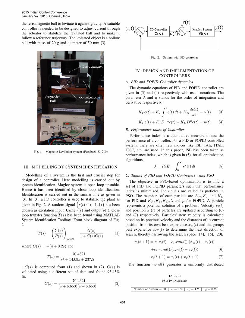
the ferromagnetic ball to levitate it against gravity. A suitablecontroller is needed to be designed to adjust current throughthe actuator to stabilize the levitated ball and to make itfollow a reference trajectory. The levitated object is a hollowball with mass of 20 g and diameter of 50 mm [3].
Fig. 1. Magnetic Levitation system (Feedback 33-210)
III. MODELLING BY SYSTEM IDENTIFICATION
Modelling of a system is the first and crucial step fordesign of a controller. Here modelling is carried out bysystem identification. Maglev system is open loop unstable.Hence it has been identified by close loop identification.Identification is carried out in the similar line as given in[3]. In [3], a PD controller is used to stabilize the plant asgiven in Fig. 2. A random signal
(r(t) ∈ (−1, 1)
)has been
chosen as excitation input. Using r(t) and output y(t), closeloop transfer function T (s) has been found using MATLABSystem Identification Toolbox. From block diagram of Fig.2
T (s) =
(Y (s)
R(s)
)yd=0
=G(s)
1 + C(s)G(s)(1)
where C(s) = −(4 + 0.2s) and
T (s) =−70.4321
s2 + 14.09s+ 237.5
. G(s) is computed from (1) and shown in (2). G(s) isvalidated using a different set of data and found 93.43%fit.
G(s) =−70.4321
(s+ 6.653)(s− 6.653)(2)
Fig. 2. System with PD controller
IV. DESIGN AND IMPLEMENTATION OFCONTROLLERS
A. PID and FOPID Controller dynamics
The dynamic equations of PID and FOPID controller aregiven in (3) and (4) respectively with usual notations. Theparameter λ and µ stands for the order of integration andderivative respectively.
KP e(t) +KI
∫ t
0
e(t) dt+KDde(t)
dt= u(t) (3)
KP e(t) +KID−λe(t) +KDD
µe(t) = u(t) (4)
B. Performance Index of Controller
Performance index is a quantitative measure to test theperformance of a controller. For a PID or FOPID controlledsystem, there are often few indices like ISE, IAE, ITAE,ITSE, etc. are used. In this paper, ISE has been taken asperformance index, which is given in (5), for all optimizationalgorithms.
J = ISE =
∫ ∞0
e2(t) dt (5)
C. Tuning of PID and FOPID Controllers using PSO
The objective in PSO-based optimization is to find aset of PID and FOPID parameters such that performanceindex is minimized. Individuals are called as particles inPSO. The members of each particle are KP ,KI and KD
for PID and KP ,KI ,KD, λ and µ for FOPID. A particlerepresents a potential solution of a problem. Velocity vi(t)and position xi(t) of particles are updated according to (6)and (7) respectively. Particles’ new velocity is calculatedbased on its previous velocity and the distances of its currentposition from its own best experience xpi(t) and the groupsbest experience xGb(t) to determine the next direction ofsearch, thereby narrowing the search space [14], [15], [20].
vi(t+ 1) = w.vi(t) + c1.rand().(xpi(t)− xi(t))
+c2.rand().(xGb(t)− xi(t)) (6)
xi(t+ 1) = xi(t) + vi(t+ 1) (7)
The function rand() generates a uniformly distributed
TABLE IPSO PARAMETERS
Number of Swarm = 50 w = 0.9 c1 = 1.2 c2 = 0.2
2015 Indian Control ConferenceJanuary 5-7, 2015. Chennai, India
464
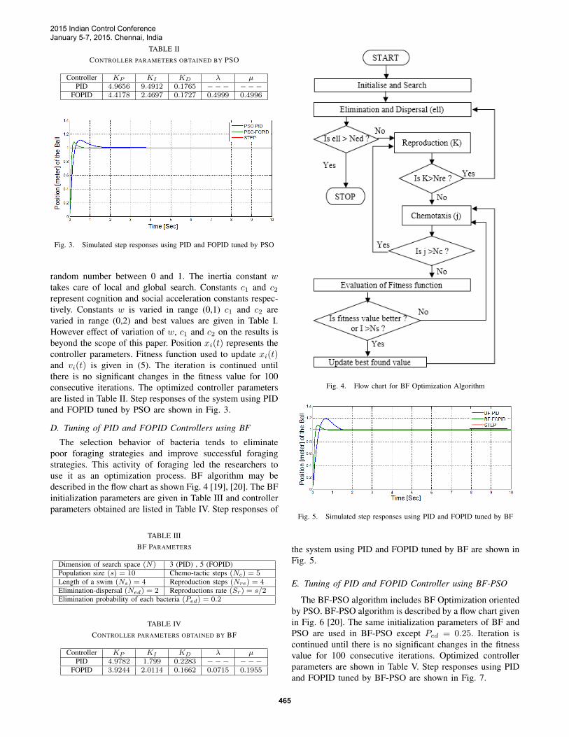
TABLE IICONTROLLER PARAMETERS OBTAINED BY PSO
Controller KP KI KD λ µPID 4.9656 9.4912 0.1765 −−− −−−
FOPID 4.4178 2.4697 0.1727 0.4999 0.4996
Fig. 3. Simulated step responses using PID and FOPID tuned by PSO
random number between 0 and 1. The inertia constant wtakes care of local and global search. Constants c1 and c2represent cognition and social acceleration constants respec-tively. Constants w is varied in range (0,1) c1 and c2 arevaried in range (0,2) and best values are given in Table I.However effect of variation of w, c1 and c2 on the results isbeyond the scope of this paper. Position xi(t) represents thecontroller parameters. Fitness function used to update xi(t)and vi(t) is given in (5). The iteration is continued untilthere is no significant changes in the fitness value for 100consecutive iterations. The optimized controller parametersare listed in Table II. Step responses of the system using PIDand FOPID tuned by PSO are shown in Fig. 3.
D. Tuning of PID and FOPID Controllers using BF
The selection behavior of bacteria tends to eliminatepoor foraging strategies and improve successful foragingstrategies. This activity of foraging led the researchers touse it as an optimization process. BF algorithm may bedescribed in the flow chart as shown Fig. 4 [19], [20]. The BFinitialization parameters are given in Table III and controllerparameters obtained are listed in Table IV. Step responses of
TABLE IIIBF PARAMETERS
Dimension of search space (N) 3 (PID) , 5 (FOPID)Population size (s) = 10 Chemo-tactic steps (Nc) = 5Length of a swim (Ns) = 4 Reproduction steps (Nre) = 4Elimination-dispersal (Ned) = 2 Reproductions rate (Sr) = s/2Elimination probability of each bacteria (Ped) = 0.2
TABLE IVCONTROLLER PARAMETERS OBTAINED BY BF
Controller KP KI KD λ µPID 4.9782 1.799 0.2283 −−− −−−
FOPID 3.9244 2.0114 0.1662 0.0715 0.1955
Fig. 4. Flow chart for BF Optimization Algorithm
Fig. 5. Simulated step responses using PID and FOPID tuned by BF
the system using PID and FOPID tuned by BF are shown inFig. 5.
E. Tuning of PID and FOPID Controller using BF-PSO
The BF-PSO algorithm includes BF Optimization orientedby PSO. BF-PSO algorithm is described by a flow chart givenin Fig. 6 [20]. The same initialization parameters of BF andPSO are used in BF-PSO except Ped = 0.25. Iteration iscontinued until there is no significant changes in the fitnessvalue for 100 consecutive iterations. Optimized controllerparameters are shown in Table V. Step responses using PIDand FOPID tuned by BF-PSO are shown in Fig. 7.
2015 Indian Control ConferenceJanuary 5-7, 2015. Chennai, India
465
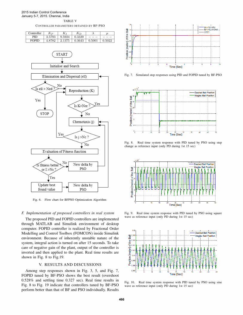
TABLE VCONTROLLER PARAMETERS OBTAINED BY BF-PSO
Controller KP KI KD λ µPID 3.5793 9.5924 0.3339 −−− −−−
FOPID 4.8782 2.1375 0.3643 0.5001 0.5022
Fig. 6. Flow chart for BFPSO Optimization Algorithm
F. Implementation of proposed controllers in real system
The proposed PID and FOPID controllers are implementedthrough MATLAB and Simulink environment of desktopcomputer. FOPID controller is realized by Fractional OrderModelling and Control Toolbox (FOMCON) inside Simulinkenvironment. Because of inherently unstable nature of thesystem, integral action is turned on after 15 seconds. To takecare of negative gain of the plant, output of the controller isinverted and then applied to the plant. Real time results areshown in Fig. 8 to Fig.19.
V. RESULTS AND DISCUSSIONS
Among step responses shown in Fig. 3, 5, and Fig. 7,FOPID tuned by BF-PSO shows the best result (overshoot0.528% and settling time 0.327 sec). Real time results inFig. 8 to Fig. 19 indicate that controllers tuned by BF-PSOperform better than that of BF and PSO individually. Results
Fig. 7. Simulated step responses using PID and FOPID tuned by BF-PSO
Fig. 8. Real time system response with PID tuned by PSO using stepchange as reference input (only PD during 1st 15 sec)
Fig. 9. Real time system response with PID tuned by PSO using squarewave as reference input (only PD during 1st 15 sec)
Fig. 10. Real time system response with PID tuned by PSO using sinewave as reference input (only PD during 1st 15 sec)
2015 Indian Control ConferenceJanuary 5-7, 2015. Chennai, India
466
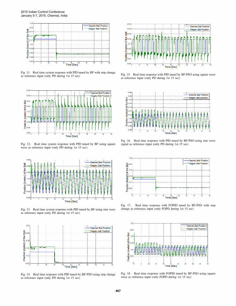
Fig. 11. Real time system response with PID tuned by BF with step changeas reference input (only PD during 1st 15 sec)
Fig. 12. Real time system response with PID tuned by BF using squarewave as reference input (only PD during 1st 15 sec)
Fig. 13. Real time system response with PID tuned by BF using sine waveas reference input (only PD during 1st 15 sec)
Fig. 14. Real time response with PID tuned by BF-PSO using step changeas reference input (only PD during 1st 15 sec)
Fig. 15. Real time response with PID tuned by BF-PSO using square waveas reference input (only PD during 1st 15 sec)
Fig. 16. Real time response with PID tuned by BF-PSO using sine wavesignal as reference input (only PD during 1st 15 sec)
Fig. 17. Real time response with FOPID tuned by BF-PSO with stepchange as reference input (only FOPD during 1st 15 sec)
Fig. 18. Real time response with FOPID tuned by BF-PSO using squarewave as reference input (only FOPD during 1st 15 sec)
2015 Indian Control ConferenceJanuary 5-7, 2015. Chennai, India
467
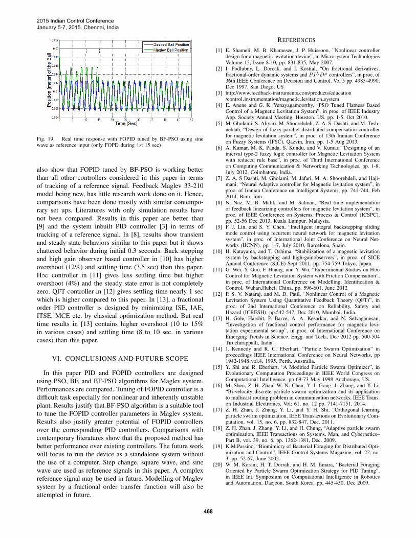
Fig. 19. Real time response with FOPID tuned by BF-PSO using sinewave as reference input (only FOPD during 1st 15 sec)
also show that FOPID tuned by BF-PSO is working betterthan all other controllers considered in this paper in termsof tracking of a reference signal. Feedback Maglev 33-210model being new, has little research work done on it. Hence,comparisons have been done mostly with similar contempo-rary set ups. Literatures with only simulation results havenot been compared. Results in this paper are better than[9] and the system inbuilt PID controller [3] in terms oftracking of a reference signal. In [8], results show transientand steady state behaviors similar to this paper but it showschattered behavior during initial 0.3 seconds. Back steppingand high gain observer based controller in [10] has higherovershoot (12%) and settling time (3.5 sec) than this paper.H∞ controller in [11] gives less settling time but higherovershoot (4%) and the steady state error is not completelyzero. QFT controller in [12] gives settling time nearly 1 secwhich is higher compared to this paper. In [13], a fractionalorder PID controller is designed by minimizing ISE, IAE,ITSE, MCE etc. by classical optimization method. But realtime results in [13] contains higher overshoot (10 to 15%in various cases) and settling time (8 to 10 sec. in variouscases) than this paper.
VI. CONCLUSIONS AND FUTURE SCOPE
In this paper PID and FOPID controllers are designedusing PSO, BF, and BF-PSO algorithms for Maglev system.Performances are compared. Tuning of FOPID controller is adifficult task especially for nonlinear and inherently unstableplant. Results justify that BF-PSO algorithm is a suitable toolto tune the FOPID controller parameters in Maglev system.Results also justify greater potential of FOPID controllersover the corresponding PID controllers. Comparisons withcontemporary literatures show that the proposed method hasbetter performance over existing controllers. The future workwill focus to run the device as a standalone system withoutthe use of a computer. Step change, square wave, and sinewave are used as reference signals in this paper. A complexreference signal may be used in future. Modelling of Maglevsystem by a fractional order transfer function will also beattempted in future.
REFERENCES
[1] E. Shameli, M. B. Khamesee, J. P. Huissoon, ”Nonlinear controllerdesign for a magnetic levitation device”, in Microsystem TechnologiesVolume 13, Issue 8-10, pp. 831-835, May 2007.
[2] I. Podlubny, L. Dorcak, and I. Kostial, “On fractional derivatives,fractional-order dynamic systems and PIλDµ controllers”, in proc. of36th IEEE Conference on Decision and Control, Vol 5 pp. 4985-4990,Dec 1997, San Diego, US
[3] http://www.feedback-instruments.com/products/education/control instrumentation/magnetic levitation system
[4] E. Anene and G. K. Venayagamoorthy, “PSO Tuned Flatness BasedControl of a Magnetic Levitation System”, in proc. of IEEE IndustryApp. Society Annual Meeting, Houston, US. pp. 1-5, Oct 2010.
[5] M. Gholami, S. Aliyari, M. Shoorehdeli, Z. A. S. Dashti, and M. Tesh-nehlab, “Design of fuzzy parallel distributed compensation controllerfor magnetic levitation system”, in proc. of 13th Iranian Conferenceon Fuzzy Systems (IFSC), Qazvin, Iran. pp. 1-5 Aug 2013,
[6] A. Kumar, M. K. Panda, S. Kundu, and V. Kumar, “Designing of aninterval type-2 fuzzy logic controller for Magnetic Levitation Systemwith reduced rule base”, in proc. of Third International Conferenceon Computing Communication & Networking Technologies, pp. 1-8,July 2012, Coimbatore, India.
[7] Z. A. S Dashti, M. Gholami, M. Jafari, M. A. Shoorehdeli, and Haji-mani, “Neural Adaptive controller for Magnetic levitation system”, inproc. of Iranian Conference on Intelligent Systems, pp. 741-744, Feb2014, Bam, Iran.
[8] N. Naz, M. B. Malik, and M. Salman, “Real time implementationof feedback linearizing controllers for magnetic levitation system”, inproc. of IEEE Conference on Systems, Process & Control (ICSPC),pp. 52-56 Dec 2013, Kuala Lumpur. Malaysia.
[9] F. J. Lin, and S. Y. Chen, “Intelligent integral backstepping slidingmode control using recurrent neural network for magnetic levitationsystem”, in proc. of International Joint Conference on Neural Net-works (IJCNN), pp. 1-7, July 2010, Barcelona, Spain.
[10] H. Katayama, and T. Oshima, “Stabilization of a magnetic levitationsystem by backstepping and high-gainobservers”, in proc. of SICEAnnual Conference (SICE) Sept 2011, pp. 754-759 Tokyo, Japan.
[11] G. Wei, Y. Guo, F. Huang, and Y. Wu, “Experimental Studies on H∞Control for Magnetic Levitation System with Friction Compensation”,in proc. of International Conference on Modelling, Identification &Control, Wuhan,Hubei, China. pp. 596-601, June 2012
[12] P. S. V. Nataraj, and M. D. Patil, “Nonlinear Control of a MagneticLevitation System Using Quantitative Feedback Theory (QFT)”, inproc. of 2nd International Conference on Reliability, Safety andHazard (ICRESH), pp.542-547, Dec 2010, Mumbai, India.
[13] H. Gole, Harshit, P. Barve, A. A. Kesarkar, and N. Selvaganesan,“Investigation of fractional control performance for magnetic levi-tation experimental set-up”, in proc. of International Conference onEmerging Trends in Science, Engg. and Tech., Dec 2012 pp. 500-504Tiruchirappalli, India.
[14] J. Kennedy and R. C. Eberhart, “Particle Swarm Optimization” inproceedings IEEE International Conference on Neural Networks, pp1942-1948 vol.4, 1995. Perth, Australia.
[15] Y. Shi and R. Eberhart, “A Modified Particle Swarm Optimizer”, inEvolutionary Computation Proceedings in IEEE World Congress onComputational Intelligence. pp 69-73 May 1998 Anchorage, US.
[16] M. Shen, Z. H. Zhan, W. N. Chen, Y. J. Gong, J. Zhang, and Y. Li,“Bi-velocity discrete particle swarm optimization and its applicationto multicast routing problem in communication networks, IEEE Trans.on Industrial Electronics, Vol: 61, no. 12 pp. 7141-7151, 2014.
[17] Z. H. Zhan, J. Zhang, Y. Li, and Y. H. Shi, “Orthogonal learningparticle swarm optimization, IEEE Transactions on Evolutionary Com-putation, vol. 15, no. 6, pp. 832-847, Dec. 2011.
[18] Z. H. Zhan, J. Zhang, Y. Li, and H. Chung, “Adaptive particle swarmoptimization, IEEE Transactions on Systems, Man, and Cybernetics–Part B, vol. 39, no. 6, pp. 1362-1381, Dec. 2009.
[19] K.M.Passino, “Biomimicry of Bacterial Foraging for Distributed Opti-mization and Control”, IEEE Control Systems Magazine, vol. 22, no.3, pp. 52-67, June 2002.
[20] W. M. Korani, H. T. Dorrah, and H. M. Emara, “Bacterial ForagingOriented by Particle Swarm Optimization Strategy for PID Tuning”,in IEEE Int. Symposium on Computational Intelligence in Roboticsand Automation, Daejeon, South Korea. pp. 445-450, Dec 2009.
2015 Indian Control ConferenceJanuary 5-7, 2015. Chennai, India
468
Copyright © 2022 FDOKUMEN