Design of Intelligent Charging Access System for Home ...
6
Design of Intelligent Charging Access System for Home Appliances Wangcheng Zhu 1,* , Xinshu Wan 1 , Taobei Lin 1 and Yun Liu 2 1 Electric Power Research Institute of Hainan Power Grid Co., Ltd., Haikou 570125, Hainan Province, China 2 Nanjing Sifang E-power Automation Co., Ltd., Nanjing 211111, Jiangsu Province, China * Corresponding author Abstract—In order to realize intelligent charging of electric equipment in the circumstances of Smart Grid, such as sweeping robots, inspection robots and automatic guided vehicles, this paper designs a new intelligent charging access system using intelligent outlet technology and wireless charging technology. Firstly, the paper illustrates the disadvantages of existing charging mode, including low-level automation and poor security. Then, this paper gives a general introduction of the new system for the above drawbacks and a detailed description of its hardware and software design. Furthermore, as for hardware facilities, the modular design is adopted, including intelligent outlet, high-frequency power supply, transmitter, receiver and on-board charger. Moreover, to realize intelligent real-time control, it takes advantage of the WiFi communication technology to reduce the difficulty and cost of intelligent access of terminal equipment. Meanwhile, with the adoption of the two- stage circuit status monitoring and abnormality judgment, the system security is improved effectively. In the last part, the paper focuses on the introduction to working flow of the system. Keywords—smart grid; intelligent power; access; wireless power transmission I. INTRODUCTION Driven by the increasing demands of energy and electricity, the world’s power grid which has experienced a leaping development from the traditional power grid to the modern power grid, from isolated urban power grids to large-scale cross-district, transnational interconnected power grid has entered a new phase marked by strong smart grid. Recently, China Southern Power Grid released The Report of Research on "the 13th Five Year" China Southern Power Grid Smart Grid (hereinafter referred to as “Report”). The Report aims to create a safe, reliable, green and efficient smart grid, which analyzes the new trend of energy transformation and development, and expounds the great strategic significance of developing smart grid. Besides, the Report constructs the development framework of the smart grid in China Southern Power Grid systematically and completely, making it clear that the significance and the future direction of smart grid, proposing a variety of interactive electricity links [1]. To build a strong smart grid smart grid, it is imperative to achieve intelligent service through mature intelligent power technology to meet the diversified needs of users, and to achieve the goal to build a steady, reliable, economic and secure power supply by constructing a new power supply- demand relationship. What’s more, the new relationship can achieve the real-time interaction of power flow, information flow, service flow between grid and customers [2]. At this stage, with the development of Smart Home level, average home users buy much more intelligent electrical equipment, such as cleaning robot, smart meters and so on. Meanwhile, the smart applications, like unattended substations, patrol robots for high voltage power lines and AGV (Automatic Guided Vehicle, AGV) at ports, are developing to a higher level and more advanced stage. The foregoing intellectualized and movable electrical devices are all powered by batteries and are connected to the power grid through wired connections of cables, so they can exchange energy with the power grid. This direct cable access charge mode has various disadvantages like requiring manual plugs to check the charging status from time to time, low level of automation and intelligence, which seriously affects the efficiency of intelligent electrical devices and the interaction with smart grid. Therefore, in order to realize the expansion of smart grid from pure power transmission network to the integration infrastructure of intelligence, energy and information, it is necessary to study the problems existing in the charging process of the intellectualized and movable electrical devices above and to explore new types of power access technology. It is also necessary to design smart and efficient electrical systems to enhance the intelligence and automation of electrical devices and to promote the interaction between electrical devices and the smart grid and to enhance the intelligence of electrical energy applications in the fields like household, industrial and power supply. Based upon the above analysis, taking AGV (Automatic Guided Vehicle) as an example, this paper conducts an overall design of the intelligent access system firstly, and then carries on a further research design of the technology involved in intelligent access system, including smart power plug, intelligent outlet technology [3], wireless power transfer technology [4], detection and recognition, as well as protection technology. Finally, merging the above-mentioned technology, this design is devoted to realize the charging detection and recognition, automatic charge, and intelligent switch functions of AGV (Automatic Guided Vehicle), which aims to improve the charging rate and reduce the charging time of electrical equipment. International Conference on Computer Science, Electronics and Communication Engineering (CSECE 2018) Copyright © 2018, the Authors. Published by Atlantis Press. This is an open access article under the CC BY-NC license (http://creativecommons.org/licenses/by-nc/4.0/). Advances in Computer Science Research, volume 80 224
-
Upload
khangminh22 -
Category
Documents
-
view
1 -
download
0
Transcript of Design of Intelligent Charging Access System for Home ...
Design of Intelligent Charging Access System for Home Appliances
Wangcheng Zhu1,*, Xinshu Wan1, Taobei Lin1 and Yun Liu2 1Electric Power Research Institute of Hainan Power Grid Co., Ltd., Haikou 570125, Hainan Province, China
2Nanjing Sifang E-power Automation Co., Ltd., Nanjing 211111, Jiangsu Province, China *Corresponding author
Abstract—In order to realize intelligent charging of electric equipment in the circumstances of Smart Grid, such as sweeping robots, inspection robots and automatic guided vehicles, this paper designs a new intelligent charging access system using intelligent outlet technology and wireless charging technology. Firstly, the paper illustrates the disadvantages of existing charging mode, including low-level automation and poor security. Then, this paper gives a general introduction of the new system for the above drawbacks and a detailed description of its hardware and software design. Furthermore, as for hardware facilities, the modular design is adopted, including intelligent outlet, high-frequency power supply, transmitter, receiver and on-board charger. Moreover, to realize intelligent real-time control, it takes advantage of the WiFi communication technology to reduce the difficulty and cost of intelligent access of terminal equipment. Meanwhile, with the adoption of the two-stage circuit status monitoring and abnormality judgment, the system security is improved effectively. In the last part, the paper focuses on the introduction to working flow of the system.
Keywords—smart grid; intelligent power; access; wireless power transmission
I. INTRODUCTION
Driven by the increasing demands of energy and electricity, the world’s power grid which has experienced a leaping development from the traditional power grid to the modern power grid, from isolated urban power grids to large-scale cross-district, transnational interconnected power grid has entered a new phase marked by strong smart grid. Recently, China Southern Power Grid released The Report of Research on "the 13th Five Year" China Southern Power Grid Smart Grid (hereinafter referred to as “Report”). The Report aims to create a safe, reliable, green and efficient smart grid, which analyzes the new trend of energy transformation and development, and expounds the great strategic significance of developing smart grid. Besides, the Report constructs the development framework of the smart grid in China Southern Power Grid systematically and completely, making it clear that the significance and the future direction of smart grid, proposing a variety of interactive electricity links [1].
To build a strong smart grid smart grid, it is imperative to achieve intelligent service through mature intelligent power technology to meet the diversified needs of users, and to achieve the goal to build a steady, reliable, economic and secure power supply by constructing a new power supply-demand relationship. What’s more, the new relationship can
achieve the real-time interaction of power flow, information flow, service flow between grid and customers [2]. At this stage, with the development of Smart Home level, average home users buy much more intelligent electrical equipment, such as cleaning robot, smart meters and so on. Meanwhile, the smart applications, like unattended substations, patrol robots for high voltage power lines and AGV (Automatic Guided Vehicle, AGV) at ports, are developing to a higher level and more advanced stage.
The foregoing intellectualized and movable electrical devices are all powered by batteries and are connected to the power grid through wired connections of cables, so they can exchange energy with the power grid. This direct cable access charge mode has various disadvantages like requiring manual plugs to check the charging status from time to time, low level of automation and intelligence, which seriously affects the efficiency of intelligent electrical devices and the interaction with smart grid. Therefore, in order to realize the expansion of smart grid from pure power transmission network to the integration infrastructure of intelligence, energy and information, it is necessary to study the problems existing in the charging process of the intellectualized and movable electrical devices above and to explore new types of power access technology. It is also necessary to design smart and efficient electrical systems to enhance the intelligence and automation of electrical devices and to promote the interaction between electrical devices and the smart grid and to enhance the intelligence of electrical energy applications in the fields like household, industrial and power supply.
Based upon the above analysis, taking AGV (Automatic Guided Vehicle) as an example, this paper conducts an overall design of the intelligent access system firstly, and then carries on a further research design of the technology involved in intelligent access system, including smart power plug, intelligent outlet technology [3], wireless power transfer technology [4], detection and recognition, as well as protection technology. Finally, merging the above-mentioned technology, this design is devoted to realize the charging detection and recognition, automatic charge, and intelligent switch functions of AGV (Automatic Guided Vehicle), which aims to improve the charging rate and reduce the charging time of electrical equipment.
International Conference on Computer Science, Electronics and Communication Engineering (CSECE 2018)
Copyright © 2018, the Authors. Published by Atlantis Press. This is an open access article under the CC BY-NC license (http://creativecommons.org/licenses/by-nc/4.0/).
Advances in Computer Science Research, volume 80
224
II. OVERALL DESIGN OF THE INTELLIGENT ACCESS
SYSTEM
A. Introduction to AGV and Its Charge Modes
AGV (Automatic Guided Vehicle), which is commonly used in industry, usually includes five parts: sensing unit, control unit (including communication), driving unit and power supply unit [5], as shown in Figure I. The sensing unit mainly consists of parts like road guide magnetic sensor, obstacle avoidance sensor and microwave photoelectric sensor, which is responsible for detecting the road information in the work area and transmitting the information to the control unit in real time. The control unit mainly consists of communication module, guidance module, route calculation and selection module. This unit is in charge of receiving the origination and destination information of the cargo handling sent by the server, and calculating the optimization route without influencing the routes of other AGVs. At the same time, the calculating results are turned into drive and detection signals and then being sent to the driving unit and sensing unit. The achievement of precise, speeding and convenient delivery relies on the coordinated control of the above two units. Driving unit is mainly composed of the drive motor, driver and controller module, guide wheel and power wheel. This unit takes charge of the real-time movement, precise handling, start-up and stop of AGV (Automatic Guided Vehicle). The power supply unit mainly has parts like battery, power management module and power information transmission module. It is obvious that this unit provides power supply, charging management and power information service for the AGV (Automatic Guided Vehicle).
Control unit
Driving unit
Power suply unit
Sensing unit
FIGURE I. SYSTEM COMPOSITION OF LATENT AGV
There are three charge modes for the latent Automatic Guided Vehicles (AGVs) including battery replacement, contacting with the ground charging brush plate, and telescopic charging lever. AGV supports both manual and automatic way to replace the battery. The alternate use of a main and a backup battery can realize 24-hour non-stop operation of AGV (Automatic Guided Vehicle). However, because the equipment occupies large area, it will cause some unsafe phenomena easily when changing the battery, for example, poor contact during cable dismantling and connection, sparks flew. As for the second charging method, AGV is parked in a fixed position where the van’s metallic brush can contact the ground charging brush plate, which makes the power transmission come true. This way also has its own shortcomings. There exists a certain voltage between the two brush plates, if any foreign metal bodies fall between two plates, it will cause short circuit, and even worse safety problems, like fire disaster. The third mode, telescopic charging rod, sets a ground telescopic charging lever in a fixed charge position, which can reach to the same height as the car chargers of AGV, therefore the power transmission is
realized when AGV arrives and contacts to the charging lever. This approach has disadvantages including inexactitude position and loose contact, which decreases charging efficiency and even causes short-circuit or electric leakage problems. Based upon the above analysis, it is necessary to bring the wireless power transmission in charging AGV in order to increase security greatly by avoiding accidents in contact charging.
B. Introduction to Wireless Power Transfer Technology
Historically, the development of wireless power transfer technology has undergone several stages includes sprout, initial exploration, continuous research, major breakthroughs and rapid development. So far, wireless power transfer can be achieved by ways like magnetic induction, magnetic coupling resonance, microwave, femtosecond laser, ultrasonic, electric field coupling [7-8].
C. System Overall Design
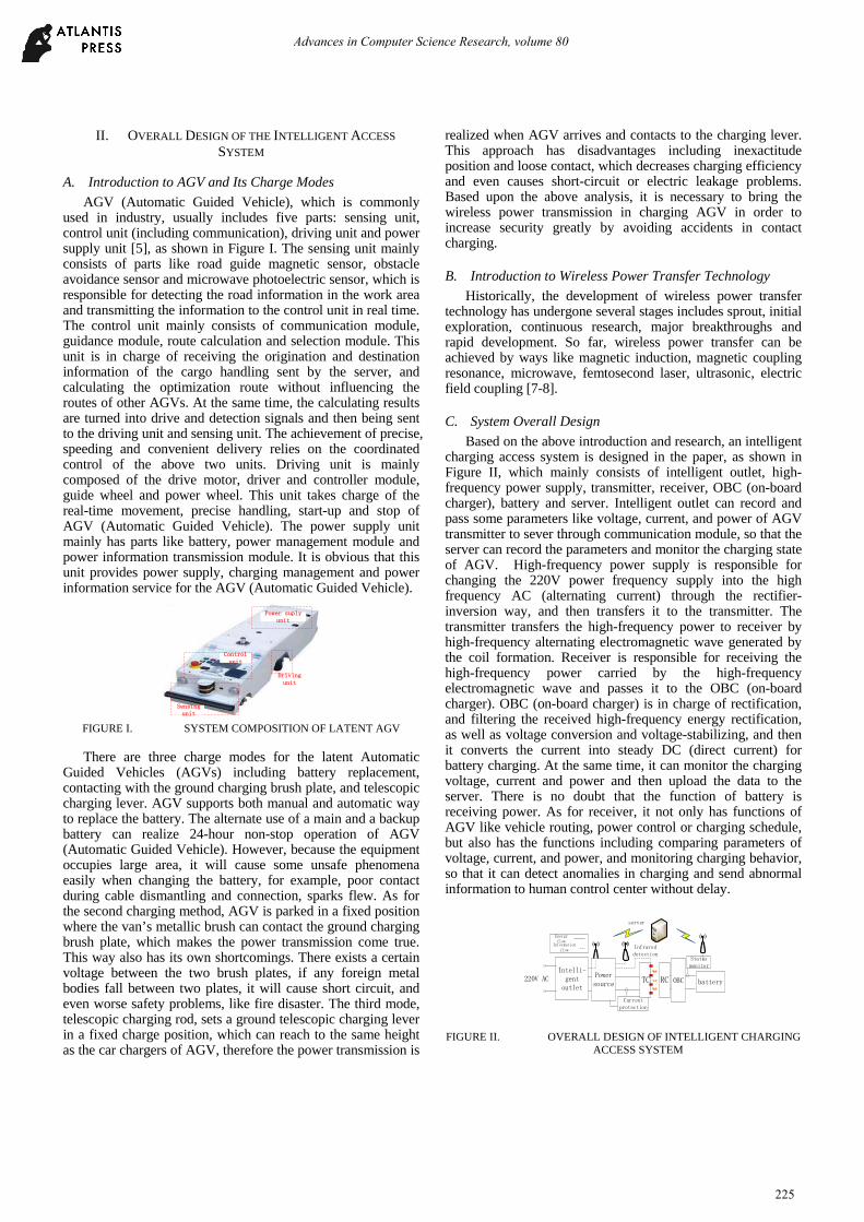
Based on the above introduction and research, an intelligent charging access system is designed in the paper, as shown in Figure II, which mainly consists of intelligent outlet, high-frequency power supply, transmitter, receiver, OBC (on-board charger), battery and server. Intelligent outlet can record and pass some parameters like voltage, current, and power of AGV transmitter to sever through communication module, so that the server can record the parameters and monitor the charging state of AGV. High-frequency power supply is responsible for changing the 220V power frequency supply into the high frequency AC (alternating current) through the rectifier-inversion way, and then transfers it to the transmitter. The transmitter transfers the high-frequency power to receiver by high-frequency alternating electromagnetic wave generated by the coil formation. Receiver is responsible for receiving the high-frequency power carried by the high-frequency electromagnetic wave and passes it to the OBC (on-board charger). OBC (on-board charger) is in charge of rectification, and filtering the received high-frequency energy rectification, as well as voltage conversion and voltage-stabilizing, and then it converts the current into steady DC (direct current) for battery charging. At the same time, it can monitor the charging voltage, current and power and then upload the data to the server. There is no doubt that the function of battery is receiving power. As for receiver, it not only has functions of AGV like vehicle routing, power control or charging schedule, but also has the functions including comparing parameters of voltage, current, and power, and monitoring charging behavior, so that it can detect anomalies in charging and send abnormal information to human control center without delay.
Intelli-gent outlet
220V AC Power source
Current protection
TC RC
Infrared detection
OBC battery
Status monitor
server
Energy flow
Information flow
FIGURE II. OVERALL DESIGN OF INTELLIGENT CHARGING
ACCESS SYSTEM
Advances in Computer Science Research, volume 80
225

III. HARDWARE DESIGN
A. Intelligent Outlet Design
The existing movable electrical devices especially AGV(Automatic Guided Vehicle)have various charging modes, and the varying applications of these devices have different scenario demands. In order to combine the wireless power transmission charging modes with the existing charging modes better and minimize the problems of reconstruction caused by charging modes change, the paper aims to design an intelligent outlet in the front end of the wireless charging system which is compatible with existing charging modes, thus reducing construction difficulties of changing charging modes.
The overall structure of intelligent outlet design is shown in Figure III, which includes MCU processing unit, WiFi communication unit, electrical parameters measurement unit, intelligent outlet system power supply unit and extension units like clock and electric relay. Under the coordination and control of the MCU processing unit, the intelligent outlet transforms the electric energy information by potential transformer and current transformer firstly, and then performs operations like signal conditioning, sampling and A / D conversion to transfer the electric energy information to MCU via the electrical parameters measurement unit; MCU analyzes and calculates the collected power information of electrical devices and then transfers the information to the server through WiFi communication unit. Electric relay can cut off the main power circuit of electrical devices when it receives the cut-off charging command from the receiving server, which usually sends this command as soon as it detects anomalies. In this way, the back-end electrical devices can be protected. Besides, the Electric relay is normally closed.
Socket
Appliances
Filtering
MCU
WiFi
Clock
PT
CT
Voltage
CurrentPower
Conditioning
sampling
A/D
conditioning
sampling A/D
7805
powersupply
L NG
Relay
Switch
FIGURE III. THE OVERALL STRUCTURE OF INTELLIGENT
OUTLET
B. High-Frequency Power Supply Design
The high-frequency power supply used in wireless power transmission can be divided into different types according to eight rules, which are introduced in detail in Table I.
TABLE I. STRUCTURE CLASSIFICATION OF HIGH-FREQUENCY POWER SUPPLY
Classification rules
Classifications
usages of electric power after inverting
active inversion Passive inversion
features of input DC
power supplyvoltage mode current mode
adjustability of output frequency
constant frequency output
variable frequency output
load current waveform
sinusoidal wave non-sinusoidal wave
output phase number
single-phase three-phase multi-phase
frequency of output DC
low frequency 50~60Hz
medium frequency 400Hz~100kHz
high frequency 100kHz~1MHz
structure form one-
terminalpush-pull
half- bridge
full-bridge
power device SCR GTO BJT MOSFET IGBT hybrid
In the process of wireless charging of AGV, considering that the power transmission distance is short, the paper chooses the operating frequency of 50-100 kHz as the high-frequency power supply, which is a moderate frequency. Besides, the rectification and filtration design of high-frequency power supply is relatively simple, so the paper mainly focuses on the introduction to inverting design. Based on the above analysis and the classifications in the table, MOSFET is more suitable for half-bridge inversion circuit.
The half-bridge inversion circuit has two capacitors with the same capacitance value and two switching devices Q1 and Q2, which alternatively performs a turn-on operation in a half period. Because the capacitor will branch voltage, the maximum output voltage of the structure can only reach up to half of input DC voltage. Under the same conditions of constant rectified DC voltage and same load, compared with the full-bridge inversion circuit, the half-bridge inversion circuit has smaller volume and drives more simply, although its output power is lower. So, half-bridge type is more suitable for AGV wireless charging system with narrow space and precise location. The structure map of high-frequency power supply with both communication and detection functions is shown in Figure IV.
C1
C2
Cj1
Cj2
C3 R1
Q1
Q2
T
1:1
Cin
Infrared detectionCurrent
protection
MCU
FIGURE IV. STRUCTURE OF HIGH-FREQUENCY POWER
SUPPLY
Advances in Computer Science Research, volume 80
226

As shown in Figure IV, the high-frequency power supply is composed of rectifier, filter, inversion, control and protection module. Rectifier module adopts four diodes full-bridge rectification form, and equips with a large capacity electrolytic capacitor in the back end for filtering. After filtering, the half-bridge inversion circuit converts the DC into high-frequency AC to the isolation transformer, which drives the transmitter coil to generate high-frequency electromagnetic field and transfers power. At the same time, in high-frequency power supply, it sets up a MCU control and protection module. On the one hand, it can generate drive waveform by controlling the driver chip and switch the MOSFET on and off; on the other hand, the current detection module, designed in the main power loop, keeps the security of high-frequency power supply by comparing with the internal threshold of MCU. Moreover, MCU can detect whether the receiver is connected to wireless charging system through the infrared sensor installed in the transmitter, so that it can control the on and off state of high-frequency power supply.
C. Transmitter and Receiver Design
The transmitter and the receiver are collectively referred to as resonator of wireless power transmission system, which is used to change high-frequency power into high frequency electromagnetic field and transfer the power to the receiver. The structure is an important part of electrical devices’ intelligent charging access system. The transmitter and the receiver are mainly composed of coils. The coils can be divided into different types according to the structure like disk spiral coil and solenoid coil. Disk spiral coil mainly includes ring coil, pancake coil and square coil. The basic structure of solenoid coil is cylindrical.
The solenoid coil is not suitable for AGV charging because AGV has small charging space, which leaves no room for solenoid coil. After comparing the three mentioned types of disk spiral coil, ring coil has lower coupling factor and quality factor, so it is unfit for wireless transmission system. Meanwhile, in order to make full use of the side charging area of AGV, it is more appropriate to adopt the square coil as the resonator part of the electrical devices’ intelligent charging access system.
Based on the above analysis, the paper designs a transmitter coil shown in Figure V. The coil adopts non-metallic material with elaborate structures. The internal part of the coil carves coil slot and coil winding plate for looping metal wires. And the external part has structures including infrared sensor hole, power input interface, power output interface and mounting hole. Infrared sensor hole is used for fixing the infrared sensor; the power input hole is used for connecting the two-core aviation plug with the metal wire to realize the power input function; the information output hole is used for connecting the infrared sensor’s signal line, power line with the high-frequency power MCU controller to achieve the transmission of power supply signal; mounting hole is used for the mounting and fixing of the transmitter bracket.
Infrared Sensor
Infrared Sensor
Power input
Information input
Fixed mounting hole
(A)TRANSMITTER COIL STRUCTURAL MAP
Coil slot
Wire route
(B)TRANSMITTER COIL PERSPECTIVE IMAGE
FIGURE V. TRANSMITTER COIL STRUCTURE
Based upon the design of the transmitter coil, the receiver coil also adopts a similar structure, i.e. the square coil. Unlike the transmitter coil, there is no need to arrange the infrared sensor on the receiver coil and the energy output hole can adopt a simple rectangular copper-core interface. Therefore, the receiver coil is lighter and smaller than the transmitter coil, which paves the way for the convenient installation on the AGV, meanwhile, it also largely reduces the AGV’s reconstruction difficulty. What’s more, the size and turns of coils, the number of sensors, the diameter of the metal wire and other parameters can be further designed according to the power and distance requirements of AGV, patrol robot and other electrical devices.
Power output Fixed mounting holes
(A)RECEIVER COIL STRUCTURAL MAP
Advances in Computer Science Research, volume 80
227

Coil slots
Wire route
(B)RECEIVER COIL PERSPECTIVE IMAGE
FIGURE VI. RECEIVER COIL STRUCTURE
D. OBC Design
The contact charging of AGV generally converts power frequency current into DC with constant voltage at first, and then transfers the DC to the receiving end of AGV for charging the AGV battery directly. Differing from contact charging, AGV wireless charging needs debugging high-frequency AC power to battery acceptable level through rectifier, filter and voltage regulation in vehicle terminal. Therefore, the intelligent charging intelligent charging access system needs to design the charger at the AGV vehicle end in order to realize the rectification, filtering and voltage regulation of the high-frequency alternating current. The circuit topology of OBC (on-board charger) designed in the paper is shown in Figure VII. The topology consists of rectifier module, filter module, chopper stabilizer module and batteries status monitoring module. What’s more, the topology can realize real-time monitoring and scheduling in the process of charging and power consumption by connecting the vehicle controller with WiFi communication unit.
battery
Lz
CzChop-ping
module
Condition monitor
Onboard controller
FIGURE VII. CIRCUIT TOPOLOGY OF OBC
E. Overall Structure Design
Onboard charger
High-frequency source
C1
C2
Cj1
Cj2
C3 R1battery
LzQ1
Q2
T
1:1
CzChop-pingmodule
TC
RC
Cinsocket
Infrared detectionCurrent
protection
MCU
Ct Cr
Status monitoring
Onboard controller
FIGURE VIII. CIRCUIT TOPOLOGY OF ELECTRICAL DEVICES’
INTELLIGENT CHARGING ACCESS SYSTEM
Based on the above research and design, considering the structure and function of each part, the circuit topology of
electrical devices’ intelligent charging access system is shown in Figure VIII. Owning to the coordination and cooperation of each part in circuit topology, many functions can be achieved, such as AGV intelligent charging, automatic switch and anomaly detection, which greatly improve efficiency of AGV.
IV. SOFTWARE DESIGN
A. Workflow of Intelligent Outlet
The workflow of intelligent outlet is shown in Figure IX. Firstly, the intelligent outlet connects with 220V power supply system, and then provides power supply for MCU and intelligent outlet system through internal rectifier and filer, meanwhile, MCU completes initialize settings. Then communication test with sever is carried out. If the communication fails, it will keep trying and turn on abnormal indicator. If the communication goes well, it will sample some signals, including voltage and current signals of outlets, besides, it will calculate power. If sampling process is unfinished, it shall check whether there are abnormalities. If so, the abnormalities shall be uploaded to sever which will send some operational orders. If the sampling is finished, it is time to check whether the voltage and current are within the normal range. If it is normal, the data shall be reported to the server, otherwise, the abnormalities shall be checked and sent to the server which will send some operation instructions, too. If the server instructs to cut off the circuit, the MCU will send a cut-off command to the electric relay to protect circuit. If the server indicates nothing, the signal sampling will continue, and the real-time monitoring of system status is realized.
Initialize MCU
Power on
Communication test
Sampling
Data transmission
Completed?
Error?Abnormality
upload
Receive command
Cut circuit?
Cut circuit
Y
N
Y
Abnormality
N
NY
Y
N
N
Y
FIGURE IX. WORKFLOW OF INTELLIGENT OUTLET
Relying on the real-time docking of intelligent outlet and server, the system realizes the detection of the first-level working status and protects the first-level circuit.
B. Workflow of High-Frequency Power Supply
The workflow of high-frequency power supply is shown in Figure X. The high-frequency power supply connects to intelligent outlet though an external three-pin plug at first, and
Advances in Computer Science Research, volume 80
228
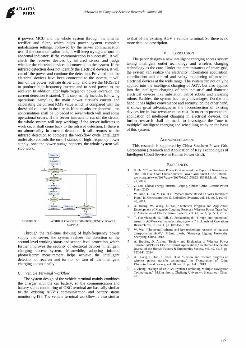
it powers MCU and the whole system through the internal rectifier and filter, which helps power system complete initialization settings. Followed by the server communication test, if the communication fails, it will keep trying and turn on abnormal indicator; if the communication is successful, it will check the receiver devices by infrared sensor and judge whether the electrical devices is connected to the system. If the infrared detection does not identify the electrical devices, it will cut off the power and continue the detection. Provided that the electrical devices have been connected to the system, it will turn on the power, activate driver chip, and drive the MOSFET to produce high-frequency current and to send power to the receiver. In addition, after high-frequency power inversion, the current detection is started. This step mainly includes following operations: sampling the main power circuit’s current and calculating the current RMS value which is compared with the threshold value set in the circuit. If the results are abnormal, the abnormalities shall be uploaded to sever which will send some operational orders. If the server instructs to cut off the circuit, the whole system will stop working; if the server indicates to work on, it shall come back to the infrared detection. If there is no abnormality in current detection, it still returns to the infrared detection to complete the workflow cycle. Intelligent outlet also controls the on-off statues of high-frequency power supply, once the power outage happens, the whole system will stop work.
Initiali-zation
Power on
Communication test?
Current detection
Upload error
Receive command
Stop working?
Cut circuit
Y
N
Y
Error?
Y
N
Infrared detection
Y
Power supply
N
N
FIGURE X. WORKFLOW OF HIGH-FREQUENCY POWER
SUPPLY
Through the real-time docking of high-frequency power supply and server, the system realizes the detection of the second-level working status and second-level protection, which further improves the security of electrical devices’ intelligent charging access system. Meanwhile, adopting infrared photoelectric measurement helps achieve the intelligent detection of receiver and turn on or turn off the intelligent charging automatically.
C. Vehicle Terminal Workflow
The system design of the vehicle terminal mainly combines the charger with the car battery, so the communication and battery status monitoring of OBC terminal are basically similar to the existing AGV’s communication and battery status monitoring [9]. The vehicle terminal workflow is also similar
to that of the existing AGV’s vehicle terminal. So there is no more detailed description.
V. CONCLUSION
The paper designs a new intelligent charging access system taking intelligent outlet technology and wireless charging technology as the core. Under the circumstances of smart grid, the system can realize the electricity information acquisition, coordination and control and safety monitoring of movable electrical devices at the wide range. The system can not only be applied into the intelligent charging of AGV, but also applied into the intelligent charging of both industrial and domestic electrical devices like substation patrol robots and cleaning robots. Besides, the system has many advantages. On the one hand, it has higher convenience and security; on the other hand, it shows great advantages in the reconstruction of existing devices for its low reconstruction cost. In order to promote the application of intelligent charging in electrical devices, the further research shall be made to investigate the “one to multiple” intelligent charging and scheduling study on the basis of this system.
ACKNOWLEDGEMENT
This research is supported by China Southern Power Grid Corporation (Research and Application of Key Technologies of Intelligent Cloud Service in Hainan Power Grid).
REFERENCES [1] S. He. “China Southern Power Grid released the Report of Research on
"the 13th Five Year" China Southern Power Grid Smart Grid.” Internet: www.csg.cn/xwzx/2017/gsyw/201708/t20170822_159482.html, [Aug. 22, 2017].
[2] Z. Liu, Global energy internet. Beijing, China: China Electric Power Press, 2015.
[3] W. Xiao, G. Su, Y. Lu, et al. “Smart Home Based on WiFi Intelligent Plug,” in Microcontrollers & Embedded Systems, vol. 14, no. 5, pp. 46-48, 2014.
[4] X. Huang, W. Wang, L. Tan, “Technical Progress and Application Development of Magnetic Coupling Resonant Wireless Power Transfer,” in Automation of Electric Power Systems, vol. 41, no. 2, pp. 2-14, 2017.
[5] T. Ganesharajah, N. Hall, C. Sriskandarajah, “Design and operational issues in AGV-served manufacturing systems,” in Annals of Operations Research, vol. 76, no. 1, pp. 109-154, 1998.
[6] W. Wu, “The overall scheme and key technology research of logistics transportation AGV,” M.Eng thesis, Shenyang Ligong University, Shenyang, China, 2013.
[7] A. Brecher, D. Arthur. “Review and Evaluation of Wireless Power Transfer (WPT) for Electric Transit Applications,” in Human Factors the Journal of the Human Factors & Ergonomics Society, vol. 49, no. 5, pp. 832-841, 2014.
[8] X. Huang, L. Tan, Z. Chen, et al, “Review and research progress on wireless power transfer technology,” in Transactions of China Electrotechnical Society, vol. 28, no. 10, pp. 1-11, 2013.
[9] J. Zhong, “Design of an AGV System Combining Multiple Navigation Technologies,” M.Eng thesis, Zhejiang University, Hangzhou, China, 2016.
Advances in Computer Science Research, volume 80
229