AUTOMATIC DRONE BATTERY CHARGING SYSTEM (INCL ...
71
TALLINN UNIVERSITY OF TECHNOLOGY SCHOOL OF ENGINEERING Department of Electrical Power Engineering and Mechatronics AUTOMATIC DRONE BATTERY CHARGING SYSTEM (INCL DOCKING SYSTEM) DROONI AKUDE AUTOMAATNE LAADIMISSÜSTEEM KOOS LAADIMISE DOKKIMISJAAMAGA MASTER THESIS Student: Fadi Al Afrange Student code: 177304MAHM Supervisor: Engineer Even Sekhri Tallinn 2020
-
Upload
khangminh22 -
Category
Documents
-
view
0 -
download
0
Transcript of AUTOMATIC DRONE BATTERY CHARGING SYSTEM (INCL ...

TALLINN UNIVERSITY OF TECHNOLOGY
SCHOOL OF ENGINEERING
Department of Electrical Power Engineering and Mechatronics
AUTOMATIC DRONE BATTERY CHARGING
SYSTEM (INCL DOCKING SYSTEM)
DROONI AKUDE AUTOMAATNE LAADIMISSÜSTEEM KOOS LAADIMISE DOKKIMISJAAMAGA
MASTER THESIS
Student: Fadi Al Afrange
Student code: 177304MAHM
Supervisor: Engineer Even Sekhri
Tallinn 2020

2
AUTHOR’S DECLARATION
Hereby I declare, that I have written this thesis independently.
No academic degree has been applied for based on this material. All works, major
viewpoints and data of the other authors used in this thesis have been referenced.
“.......” .................... 20…..
Author: ..............................
/signature /
Thesis is in accordance with terms and requirements
“.......” .................... 20…..
Supervisor: ….........................
/signature/
Accepted for defence
“.......” .................... 20…..
Chairman of theses defence commission: .................................................
/name and signature/
3
Non-exclusive Licence for Publication and Reproduction of GraduationTthesis¹
I, FADI AL AFRANGE (date of birth: 29.01.1993) hereby
1. grant Tallinn University of Technology (TalTech) a non-exclusive license for my thesis
AUTOMATIC DRONE BATTERY CHARGING SYSTEM (INCL DOCKING SYSTEM)
DROONI AKUDE AUTOMAATNE LAADIMISSÜSTEEM KOOS LAADIMISE
DOKKIMISJAAMAGA
supervised by
Engineer, Even Sekhri
1.1 reproduced for the purposes of preservation and electronic publication, incl. to be
entered in the digital collection of TalTech library until expiry of the term of
copyright;
1.2 published via the web of TalTech, incl. to be entered in the digital collection of
TalTech library until expiry of the term of copyright.
1.3 I am aware that the author also retains the rights specified in clause 1 of this
license.
2. I confirm that granting the non-exclusive license does not infringe third persons'
intellectual property rights, the rights arising from the Personal Data Protection Act or
rights arising from other legislation.
¹ Non-exclusive Licence for Publication and Reproduction of Graduation Thesis is not valid during
the validity period of restriction on access, except the university`s right to reproduce the thesis
only for preservation purposes.
______________ (signature)
______________ (date)

4
Department of Electrical Power Engineering and Mechatronics
THESIS TASK
Student: Fadi Al Afrange, 177304MAHM
Study programme,
main speciality: MAHM, Mechatronics
Supervisor(s): Engineer Even Sekhri, +372 620 3306
Thesis topic:
(in English) AUTOMATIC DRONE BATTERY CHARGING SYSTEM (INCL DOCKING
SYSTEM)
(in Estonian) DROONI AKUDE AUTOMAATNE LAADIMISSÜSTEEM KOOS LAADIMISE
DOKKIMISJAAMAGA
Thesis main objectives:
1. Achieve drone flight and land autonomously
2. Charging drone battery wirelessly
3. Fully charge the battery within 1.5 hours
4. Build an automatic charging station
Thesis tasks and time schedule:
No Task description Deadline
1. Achieve drone flight and land autonomously 01.02.2020
2. Charging drone battery wirelessly 01.03.2020
3. Fully charge the battery within 1.5 hours 01.03.2020
4. Build an automatic charging station 01.04.2020
Language: English Deadline for submission of thesis: “22” May 2020
Student: FADI AL AFRANGE .......……........ “.......”..............2020
/signature/
Supervisor: EVEN SEKHRI .......……........ “.......”..............2020
/signature/
Head of study programme: MART TAMRE .......……........ “.......”..............2020
/signature/

5
TABLE OF CONTENTS
TABLE OF CONTENTS ......................................................................................... 5
TABLE OF FIGURES ............................................................................................ 7
TABLE OF TABLES .............................................................................................. 9
PREFACE .........................................................................................................10
LIST OF ABBREVIATIONS AND SYMBOLS .............................................................11
INTRODUCTION ................................................................................................12
Thesis structure ............................................................................................13
1. Literature overview/analysis ........................................................................14
1.1 Historical background ...........................................................................14
1.2 Autonomous battery charging using conductive power transfer ..................14
1.3 Wireless power transmission using solar panels ........................................16
1.3.1 History ....................................................................................................16
1.3.2 Tesla’s experiment ...................................................................................16
1.3.3 A study on drone charging system using wireless power transmission .............17
1.4 Automated battery swap and recharge ....................................................18
1.5 Solar charging UAV ...............................................................................19
1.5.1 Eagle eye drone .......................................................................................19
1.6 Conclusion ...........................................................................................20
2. Autonomous drone and precision landing ......................................................22
2.1 Autonomous drone ...............................................................................22
2.2 Autonomous take-off and hovering .........................................................23
2.3 Precision landing ..................................................................................24
2.4 Programme flow ...................................................................................25
3. Wireless charging.......................................................................................27
3.1 Wireless charger ..................................................................................28
3.1.1 Transmitter description .............................................................................29
3.1.2 Receiver description .................................................................................30
3.2 Wireless charger assembly and system setup ...........................................32
4. Wireless charger station .............................................................................35
4.1 Station design ......................................................................................35
4.2 Mechanical alignment mechanism design .................................................36
4.2.1 Linear actuators .......................................................................................36
4.3 Steel structure .....................................................................................37
4.4 Station controller .................................................................................38
4.5 Motor drivers .......................................................................................39
4.6 Object detection ...................................................................................43

6
4.7 Station assembly ..................................................................................44
4.8 Programme flow ...................................................................................45
5. Experimental results ..................................................................................48
5.1 Efficiency of the WPT ............................................................................48
5.2 Performance with the battery charger .....................................................49
5.3 Performance under misalignment ...........................................................49
5.4 Performance with vertical distance .........................................................50
5.5 Thermal issues .....................................................................................50
6. Future work ..............................................................................................52
6.1 Custom made battery charger ................................................................52
6.2 Addressing misalignment.......................................................................52
6.3 Linear actuator accuracy .......................................................................53
7. Conclusion ................................................................................................54
SUMMARY ........................................................................................................55
KOKKUVÕTE ....................................................................................................56
LIST OF REFERENCES .......................................................................................57
APPENDICES ....................................................................................................62
Appendix 1 ...................................................................................................62
Appendix 2 ...................................................................................................68

7
TABLE OF FIGURES
Figure 1.1 Image tracking system [5] .................................................................15
Figure 1.2 Station design flow chart [6] ...............................................................15
Figure 1.3 Drone in operation [10]......................................................................17
Figure 1.4 Drone charging on station [10] ...........................................................17
Figure 1.5 CAD Design of battery carrier [11] ......................................................18
Figure 1.6 CAD Design of landing station [11] ......................................................18
Figure 1.7 Solar powered UAV [12] .....................................................................19
Figure 1.8 Eagle eye drone [13] .........................................................................20
Figure 2.1 Parrot AR.Drone 2.0 [15] ...................................................................22
Figure 2.2 Drone program interface ....................................................................23
Figure 2.3 Black and white oriented roundel landing Image [16].............................24
Figure 2.4 Drone flow chart ...............................................................................25
Figure 3.1 Parrot AR. Drone 2.0 HD Battery [18] ..................................................27
Figure 3.2 Turnigy 1500mAh 3S 20C Lipo Pack [19]..............................................27
Figure 3.3 Wireless power transfer concept [20] ...................................................28
Figure 3.4 Semtech TSDMTX-24V3-EVM transmitter [22] ......................................29
Figure 3.5 TX LED Behaviour ..............................................................................30
Figure 3.6 TSDMRX-19V/40W-EVM receiver [23] ..................................................31
Figure 3.7 Charsoon DC-4S 2-4S Li-Poly/Li-Ion Battery Balance Charger [25] ..........32
Figure 3.8 LM2596 DC-DC Step-down buck converter [27] ....................................33
Figure 3.9 Power flow to the drone battery ..........................................................33
Figure 3.10 Wireless power transmitter placed under the base plate .......................34
Figure 3.11 Wireless power receiver placed under the drone ..................................34
Figure 4.1 Station design ...................................................................................35
Figure 4.2 Alignment mechanism ........................................................................36
Figure 4.3 Hiwin LAM1 Linear actuator [28] .........................................................36
Figure 4.4 Qinhuangdao PA-14P linear actuator [29] .............................................37
Figure 4.5 Steel structure design ........................................................................38
Figure 4.6 Arduino Mega 2560 [30] ....................................................................38
Figure 4.7 BTS7960 - 43A Motor drive .................................................................39
Figure 4.8 BTS7960 - 43A Wiring schematic [32] ..................................................40
Figure 4.9 L298N Motor driver [34] .....................................................................41
Figure 4.10 L298N Wiring schematic ...................................................................42
Figure 4.11 SRF05 Ultrasonic distance sensor [37] ...............................................43
Figure 4.12 SRF05 wiring schematic ....................................................................44

8
Figure 4.13 Automatic station assembly ..............................................................45
Figure 4.14 Station programme flowchart ............................................................46
Figure 5.1 Efficiency of Semtech EVM wireless charger at different load current........48
Figure 5.2 TX board 54.1° C ..............................................................................51
Figure 5.3 RX board 60.6° C ..............................................................................51

9
TABLE OF TABLES
Table 4.1 BTS7960 Control input pin function [33] ................................................40
Table 4.2 BTS7960 Motor power supply and output pin assignment [33] .................41
Table 4.3 L298N Motor controller truth table [36] .................................................42

10
PREFACE
This thesis topic was proposed by the Department of Electrical Power Engineering and
Mechatronics at Tallinn University of Technology.
I am grateful to Professor Mart Tamre, Head of Mechatronics Engineering at Tallinn
University of Technology, who supported me from the beginning of this project up to
the end of it, he made it all possible for me to achieve my task.
I would like to thank my supervisor, Even Sekhri for all the help he provided to me for
supplying all the needed requirements and guiding me to write my thesis.
Finally, I would like to thank Dhanushka Chamara Liyanage for helping me in some
technical issues I had and also for providing me with the necessary needs.
Keywords: Drone, Autonomous flight, Object recognition, Wireless charger,
Automatic charging system

11
LIST OF ABBREVIATIONS AND SYMBOLS
FFA Federal Aviation Administration
UAV Unmanned Aerial Vehicle
GPS Global Positioning System
AC Alternating Current
DC Direct Current
PCB Printed Circuit Board
WPT Wireless Power Transmission
API Application Program Interface
SDK Software Development Kit
PC Personal Computer
LED Light Emitting Diode
VDC Volts Direct Current
PWM Pulse Width Modulation
HD High Density
FOD Foreign Object Detection
12
INTRODUCTION
Over the last few years, drones have been emerging into the public sphere of life. The
Federal Aviation Administration (FAA) Predicts there is going to be more than 7 million
drones in the U.S. airspace by 2020 [1]. It is not only about increasing the number but
they are also becoming smarter. With the advanced technology in drones, they became
fully or partially autonomous in the market and their use became more in many fields
like cinematography and photography.
In 2018, Intel broke the world record number for flying drones simultaneously in the
opening ceremony of winter Olympics using 1,218 drones to create a dazzling light show
simultaneously [2]. With technological advancement, drones are becoming more
relevant in society. Amazon has launched its first Prime Air Delivery in 2016 and they
are trying to expand its autonomous drone delivery service, the service uses
autonomous drones to deliver the individual package within 30 minutes of ordering.
Autonomous drones can be used for surveillance and security. Drones are being used
by some farmers nowadays to monitor the growth of crop quality [3]. They can be used
as a communication network points. Drones can play a critical pivotal role in case of
earthquake or fire in the forest to detect trapped humans. In spite of the fact that
autonomous drones are able to do many applications with its huge potential, they are
confined to certain flight time. The top longest flight time in 2020 was about 30 minutes
by Autel Robotics EVO Drone [4]. Moreover, human interference to manually charge the
battery of the drone removes the self-rule of autonomy. Charging the drone's battery
manually in many applications can reduce the reliance on the drone as a human has
always to be there to do that and it becomes very difficult in case of applications that
use a large number of drones.
A potential solution to make the drones free of human intervention and to expand its
area of working is by making an autonomous wireless charging station. Those stations
can let the drones charge themselves anytime and can be placed in a strategical location
where drones can land whenever the battery is going low and then take off again to
continue its task or route. This kind of platform eliminates completely the concept of
going back always to the home base every time it needs to be charged.
The autonomous wireless charger for drones has more advantages than wired or contact
charging pad due to its robustness, it is possible to make it waterproof and thus weather
insensitive. The wireless charger is also convenient as it can communicate between the
transmitter and receiver to automate the process without relying on a mechanical
complexity or wired connections to know the state of the battery. As a company who

13
needs to use many drones, this platform will increase the efficiency and make the work
fully autonomous.
Over the summary, a wireless charger has been used for this project to efficiently charge
the drone within 1.5 hours wirelessly once it lands on the charger station.
Thesis structure
This thesis is organized in seven main chapters, and followed by a summary, references
and appendices, at the end.
Chapter 1 presents the literature overview/analysis. It provides previous works about
automatic battery charging for drones. Then, a comparison between all of them followed
by a conclusion.
Chapter 2 is about achieving autonomous flight and precise landing.
Chapter 3 provides all the details regarding the chosen wireless charger.
Chapter 4 shows the charging station design. Also, the mechanical mechanism design
was used to align the drone after landing and discusses the program flow.
Chapter 5 discuss the experimental results after running the system, the efficiency of
the wireless charger, performance under different cases and the thermal issues.
Chapter 6 is about future work that can be done to improve the system and achieve
better results.
Chapter 7 is a conclusion for the whole project.
14
1. LITERATURE OVERVIEW/ANALYSIS
1.1 Historical background
The growth of drones is being enormously wide nowadays with the advancement in
technology and their cooperation in consumer electronics. These drones were originally
used for fulfilling military purposes. In the beginning, they were controlled by radio
waves using a remote control as a weapon such as missiles. In 1839, the Austrian
soldiers attacked the Italian city Venice using unmanned aerial vehicles holding
explosives and that was earliest seen for the unmanned aerial vehicle. However, they
were in the form of balloons which is not similar to the current drone shape that works
in the piloted aircraft for shooting missiles. Nowadays, there are much more nonmilitary
applications these drones can be used for as their functions became much wider such
as monitoring, delivering, film recording and entertainment.
1.2 Autonomous battery charging using conductive
power transfer
The flight time of drones is quite limited because of the high power consumed from the
battery. Providing additional battery is not a practical solution to the problem because
adding more weight will utilize more power, resulting in the same problem. A potential
solution was made in this project by a team from the University of Connecticut. The
team used the conductive charging method to charge the battery and has decided to
build a UAV station that would charge the drone autonomously without requiring human
interference. The team developed an autonomous structure that is able to navigate the
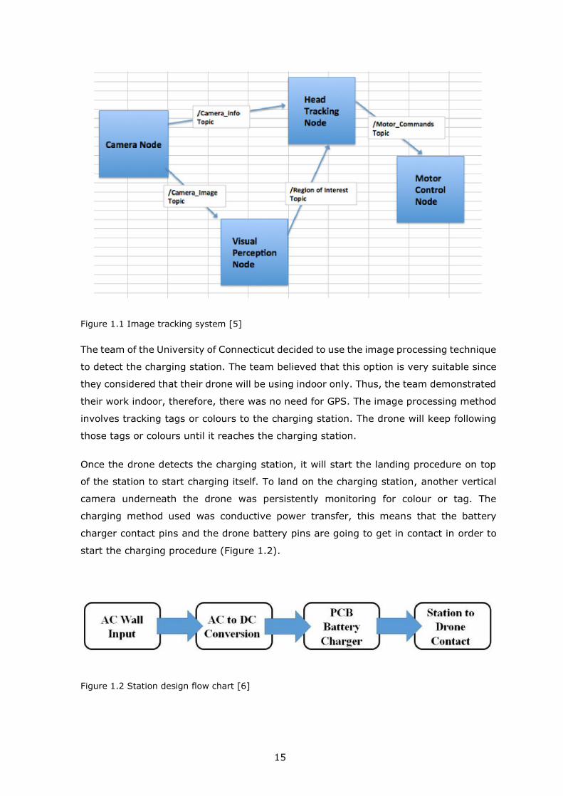
unmanned aerial vehicle to the charging location (Figure 1.1). Thus, charging the drone
battery without human interference [5].
15
Figure 1.1 Image tracking system [5]
The team of the University of Connecticut decided to use the image processing technique
to detect the charging station. The team believed that this option is very suitable since
they considered that their drone will be using indoor only. Thus, the team demonstrated
their work indoor, therefore, there was no need for GPS. The image processing method
involves tracking tags or colours to the charging station. The drone will keep following
those tags or colours until it reaches the charging station.
Once the drone detects the charging station, it will start the landing procedure on top
of the station to start charging itself. To land on the charging station, another vertical
camera underneath the drone was persistently monitoring for colour or tag. The
charging method used was conductive power transfer, this means that the battery
charger contact pins and the drone battery pins are going to get in contact in order to
start the charging procedure (Figure 1.2).
Figure 1.2 Station design flow chart [6]

16
1.3 Wireless power transmission using solar panels
1.3.1 History
Andre-Marie Ampere developed ampere's circuital law in 1826 proving that electric
current produces a magnetic field. The law of induction was developed by Michael
Faraday In 1831, Faraday’s law, explains that the electromagnetic force induced in a
conductor by time-varying magnetic flux. James Clark Maxwell synthesized these and
other experiment, observations and equations of electricity, optics and magnetism into
a consistent theory, deriving Maxwell's equations in 1862. The basis of the modern
electromagnetic including the wireless power transmission of electrical energy was
formed from those set of partial differential equations.
1.3.2 Tesla’s experiment
In 1891, at Columbia College in New York, a lecture was demonstrating by Tesla about
wireless power transmission. Using two metal sheets, he applied a high-frequency
oscillating voltage on them. Similar to the neon lights, the electric field between the two
sheets ionizes the low gas pressure in the Geissler tubes causing them to glow by
fluorescence.
In 1899, at Colorado Springs, Tesla made an experiment in the resonant inductive
transfer. Tesla's magnifying transmitter in resonance with the coil nearby powered a
light bulb. The inventor Nikola Tesla implemented the first experiments in the wireless
power transmission field at the turn of the 20th century, he put so much effort to
popularize the idea. He made an experiment to transmit the power by capacitive and
inductive coupling using a spark-excited radiofrequency resonant transformer in the
period between 1891 to 1904 which generated an AC voltage and now it is called Tesla
coils. He was successfully able to transmit the power in very small distances with no
wires. Later on, using resonant inductive coupling, he was able to increase the distance
by using an LC receiving circuit in resonance with the transmitter LC circuit and
demonstrated that by lit a bulb in the American Institute of Electrical Engineers.
During 1899 to 1900, Tesla used a high voltage of about 10 megavolts that was
generated by an enormous coil at his laboratory in Colorado Springs. At a distance of
about thirty meters, He was able to lit up three incandescent lamps. Tesla's resonant
inductive coupling pioneered is nowadays used throughout electronics and became a

17
familiar technology which is currently applied to short-distance wireless power transfer
systems [7][8].
1.3.3 A study on drone charging system using wireless power
transmission
This study was developed by Chang Wook Park and Hee Tae Chung to charge the drone
wirelessly. The system radio frequency harvesting uses a circular spiral indicator
antenna to charge the drone wirelessly. The distance between the harvesting circuit and
drone charging station is kept as short as possible in order to transfer the maximum
power value from the harvesting system to the drone battery [9][10]. The design of the
system is shown in Figure 1.3 and the operation is shown in Figure 1.4.
Figure 1.3 Drone in operation [10]
Figure 1.4 Drone charging on station [10]

18
The station is supplied by the power that is generated from solar panels. It is placed in
a high location which makes it easy for the drone to land and allows the solar panels to
get much more amount of power.
1.4 Automated battery swap and recharge
This system was proposed by Tuna Tokosoz, it basically uses a mechanical mechanism
to automatically swap the battery placed on the drone after landing and replace it with
a fully charged one, the battery swapped will be moved to the charger unit in order to
fully charge it by the return time of the drone. The author showed a hardware platform
for the presented system. It uses a buffer of 8 batteries organized in a dual-drum
structure that allows swapping the batteries. It is possible to use the system to swap
more than one battery for several drones. The hardware implementation is shown in
Figure 1.5 and Figure 1.6.
Figure 1.5 CAD Design of battery carrier [11]
Figure 1.6 CAD Design of landing station [11]

19
1.5 Solar charging UAV
Solar power can be another solution to re-energize the drones despite that it is not so
common for consumers to use yet. Solar-powered drones are not mainstream for
charging drones. This technology is in developing and could be interesting to have it as
an alternative solution to battery-powered drones. However, installing solar panels to
increase the drones flight time compared to other drones that have to land after a short
period of time for recharging can be limited to winged drones so far (Figure 1.7).
Figure 1.7 Solar powered UAV [12]
1.5.1 Eagle eye drone
One of the big challenges drones have is the need to charge their battery after a short
flight time. However, two engineers from France, Baptista and Pietroiusti have designed
what they call the Eagle Eye drone [13]. This drone was designed to have solar panels
on its top surface. Thus, it recharges itself during flying in the air and does not need to
land. Its main purpose design was for areas with hidden dangers in distant places. The
drone can provide information such as the change occurred on the ground or trees. It
was developed to keep the people secured while having their wild expeditions. Thus, it
became an important device for rescuers due to its high characteristics (Figure 1.8).

20
Figure 1.8 Eagle eye drone [13]
1.6 Conclusion
The projects listed above touch on all aspects that relate to this project and they are all
relevant to one major point. All projects that have been discussed and analyzed above
will be compared with this project.
Firstly, the conducive power transmission charger, this project is low in cost and can
provide autonomous charging process but, it cannot be generalized to more than a small
number of drones due to its structural design as it charges with its contact pins which
suit one type of battery. Also, if the design of the drone is different even with the same
battery type, this project will not be able to work.
The second project is the WPT using solar power, it is quite similar to this thesis project
except that it has different docking design and its main source of power is coming from
solar panels. This project has low power transfer and could be impossible in some
countries as the sunlight might not exist all day.
Another project is the battery swapping, it is quite an interesting project as it saves the
time required for the drone battery to be charged as it does not require time to charge
the battery because there will be a full battery waiting to be swapped with the empty
one but, the swap design mechanism will not fit with more than a certain number of
drones as it has a limited-range mechanical system.

21
Lastly, the solar-powered drone could be the future to solve the battery-powered drones
but as for the moment, the drones that have this kind of technology are limited to fixed
wings and has a high cost.
The idea in this thesis is to come-up with a fast drone charging system, which is not
only cheap but also can assist in drone landing and charging autonomously. The solution
will have generalization ability to charge different kinds of drones. Also, a generalized
communication protocol will be used between transmitter and receiver which
simultaneously will save energy.
22
2. AUTONOMOUS DRONE AND PRECISION LANDING
This chapter is about the selected drone’s features and API used to program the drone
autonomously to take-off, hover and land. Also, the strategy was used to land on the
station precisely.
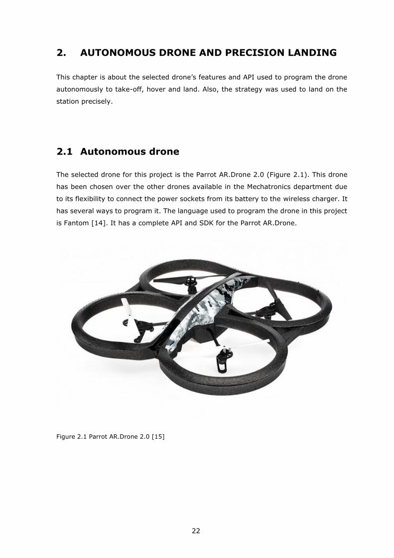
2.1 Autonomous drone
The selected drone for this project is the Parrot AR.Drone 2.0 (Figure 2.1). This drone
has been chosen over the other drones available in the Mechatronics department due
to its flexibility to connect the power sockets from its battery to the wireless charger. It
has several ways to program it. The language used to program the drone in this project
is Fantom [14]. It has a complete API and SDK for the Parrot AR.Drone.
Figure 2.1 Parrot AR.Drone 2.0 [15]
23
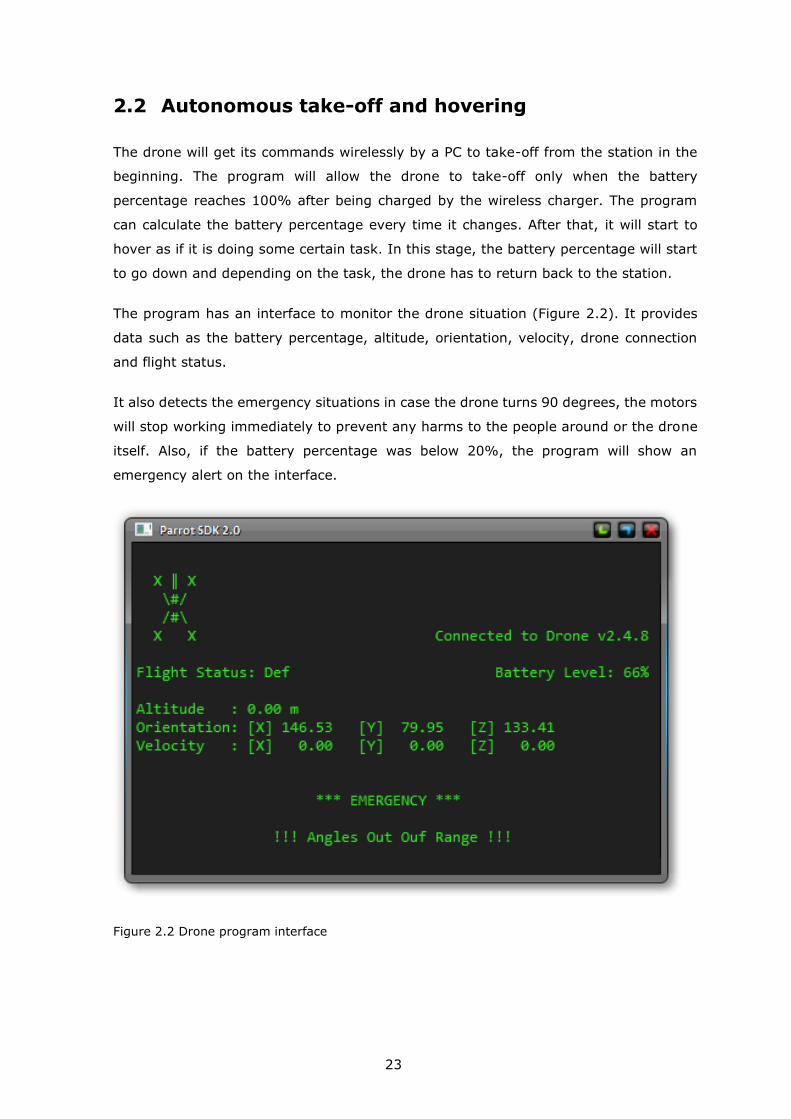
2.2 Autonomous take-off and hovering
The drone will get its commands wirelessly by a PC to take-off from the station in the
beginning. The program will allow the drone to take-off only when the battery
percentage reaches 100% after being charged by the wireless charger. The program
can calculate the battery percentage every time it changes. After that, it will start to
hover as if it is doing some certain task. In this stage, the battery percentage will start
to go down and depending on the task, the drone has to return back to the station.
The program has an interface to monitor the drone situation (Figure 2.2). It provides
data such as the battery percentage, altitude, orientation, velocity, drone connection
and flight status.
It also detects the emergency situations in case the drone turns 90 degrees, the motors
will stop working immediately to prevent any harms to the people around or the drone
itself. Also, if the battery percentage was below 20%, the program will show an
emergency alert on the interface.
Figure 2.2 Drone program interface

24
2.3 Precision landing
The automatic landing procedure can start only if the battery percentage is equal or
below 20% for safety reasons. Another reason is that some of the cells in the lithium
battery might go very low in case the battery percentage went too low which cause a
failure in the charging process because of the high consumption that would be hard to
balance charge them later on.
Landing a drone precisely on a specific coordinate is quite difficult. Thus, image
processing has been used to detect an image on the station, there are two integrated
cameras in the Parrot AR drone, one is horizontal, and another is vertical. The vertical
camera in the drone was used to detect an oriented roundel image (Figure 2.3) which
was placed on the landing station. The image color used to detect the station landing
pad is black and white due to the low camera resolution. Even then, the drone usually
has a few centimeters variance from the exact coordinate which will require a
mechanical mechanism to adjust that.
Figure 2.3 Black and white oriented roundel landing Image [16]
25
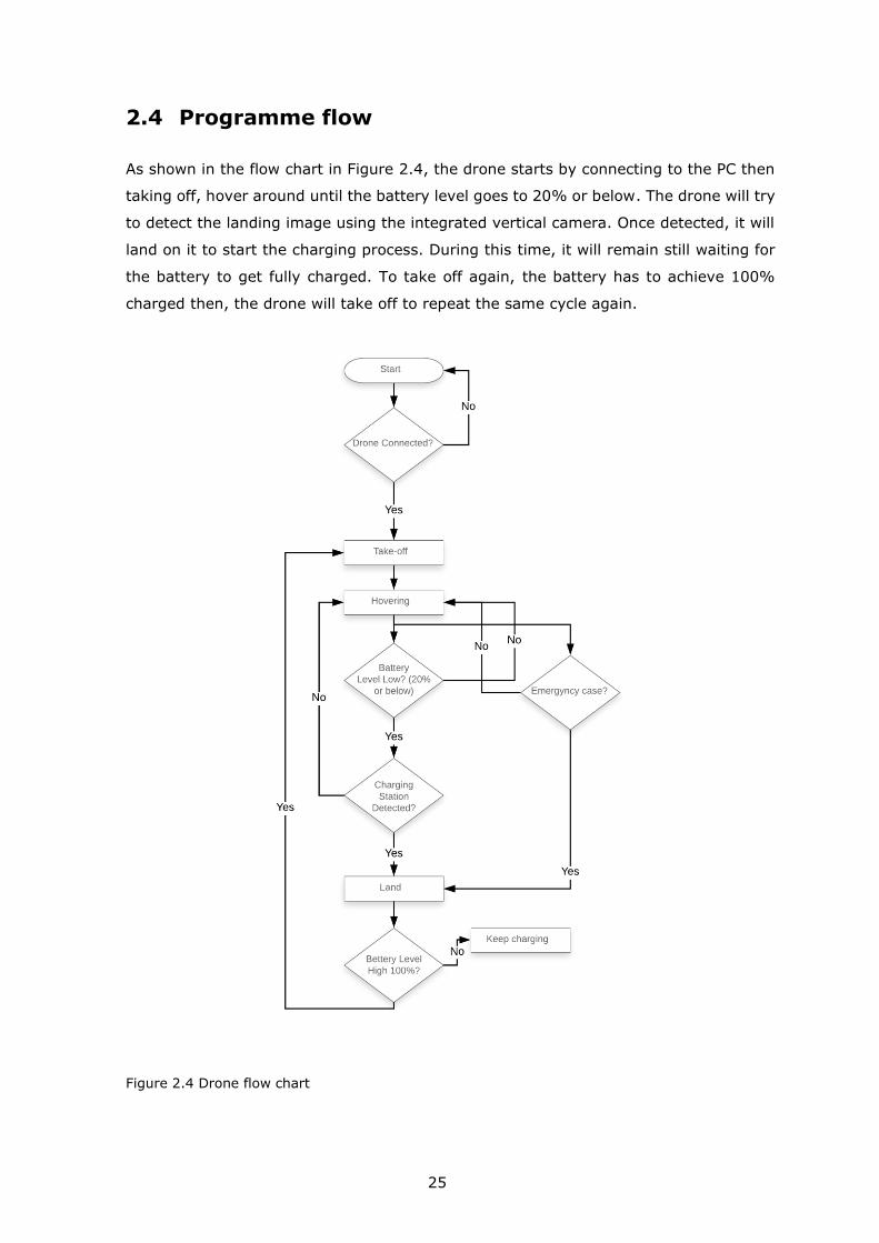
2.4 Programme flow
As shown in the flow chart in Figure 2.4, the drone starts by connecting to the PC then
taking off, hover around until the battery level goes to 20% or below. The drone will try
to detect the landing image using the integrated vertical camera. Once detected, it will
land on it to start the charging process. During this time, it will remain still waiting for
the battery to get fully charged. To take off again, the battery has to achieve 100%
charged then, the drone will take off to repeat the same cycle again.
Figure 2.4 Drone flow chart

26
It was programmed to act in emergency cases such as strong wind that would possibly
hit it to turn it 90 degrees. In that case, the motors will stop immediately. Also, it will
alert an emergency flag showing on the PC in case the battery level is 20% or below.

27
3. WIRELESS CHARGING
In this chapter of the thesis, all details about the wireless charger will be explained, how
it was chosen based on the calculations in accordance with our requirements. Also, the
features and specifications of this charger will be explained in full detail.
The Parrot drone’s battery is a three-cell Lithium-Polymer battery (Figure 3.1) that has
a capacity of 1500 mAh at 11.1 volts and a discharge capacity of 10C [17]. The HD
battery has two connectors, one for discharging to power the AR.Drone 2.0 and other
connectors for balance charging the battery, the estimated flight time is 18 minutes.
Figure 3.1 Parrot AR. Drone 2.0 HD Battery [18]
A similar battery was used in this project because it was difficult to use the pins located
on the HD battery to charge them. For this reason, a Turnigy battery (Figure 3.2) was
used instead which has almost the same specifications except for the discharge capacity
which is 20C in this battery [19].
Figure 3.2 Turnigy 1500mAh 3S 20C Lipo Pack [19]

28
To charge the Parrot drone’s battery within 1.5 hours, 16.65 watts of power is needed
(11.1 volts 1.5 amps). However, most commercial wireless chargers that could be found
online does not exceed 10 watts which are mostly cell phone chargers as this field is
still growing for other applications but, few companies offer more than 10 watts.
3.1 Wireless charger
The wireless charger consists of two parts, transmitter and receiver, the transmitter is
the actual charging station while the receiver is usually located inside the device that
requires to charge its battery. The wireless charger transmits energy from a power
source to a device without wires or cables. The current is provided to a primary coil in
the transmitter that produces an electromagnetic (EM) field and in this field, there is a
secondary coil placed in the receiver to receive the transmitted current (Figure 3.3).
However, unlike the typical power transformer that operates at a line frequency and
requires an iron core, the wireless charger was designed to operate at the range of 100
kHz which makes it perform efficiently with an air core.
Figure 3.3 Wireless power transfer concept [20]
Wireless power transfer systems are divided into three power categories. Low power
range up to 3 watts such as headsets and medical sensors, medium power range in the
range of 5 to 15 watts such as cell phones. High power systems such as radio-controlled
devices (RC) and other equipment requiring 15 to 100 watts of power.
29
The wireless charger that was chosen for this project is Semtech LKCH-TXRX40W-EVB.
This wireless charger has 40 Watts output and apart from being able to transmit more
than needed for this project, they are intelligently managed. A transmitter will provide
power only when the receiver is present and will produce the amount of power the
receiver requested. In addition, it can recognize if there is an interruption in the
electromagnetic field that may occur by a foreign object and will stop transferring power
to prevent any amount of power being absorbed by anything but a proper receiver. The
communication protocol this wireless charger has will continuously provide the needed
power even if it differs from time to time as requested by the receiver, if the receiver
requires no more power, such as the battery is fully charged, it can request no more
power and the transmitter will act according to that and stop transmitting power to the
receiver.
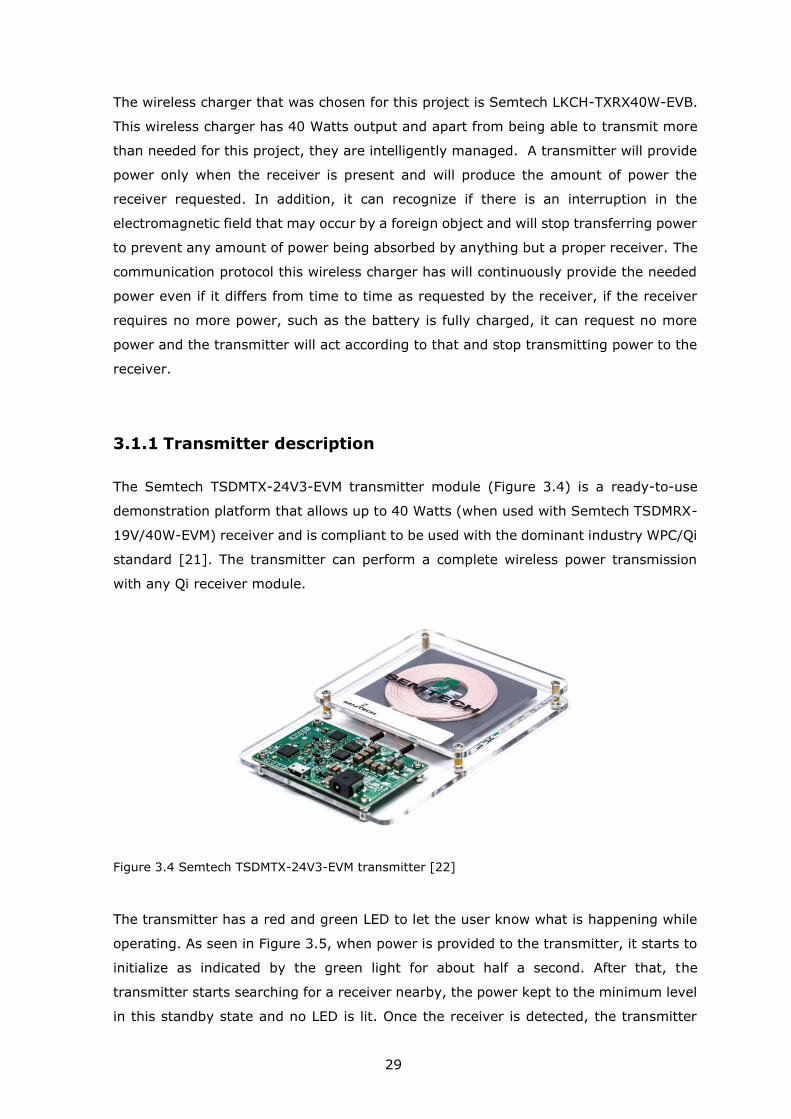
3.1.1 Transmitter description
The Semtech TSDMTX-24V3-EVM transmitter module (Figure 3.4) is a ready-to-use
demonstration platform that allows up to 40 Watts (when used with Semtech TSDMRX-
19V/40W-EVM) receiver and is compliant to be used with the dominant industry WPC/Qi
standard [21]. The transmitter can perform a complete wireless power transmission
with any Qi receiver module.
Figure 3.4 Semtech TSDMTX-24V3-EVM transmitter [22]
The transmitter has a red and green LED to let the user know what is happening while
operating. As seen in Figure 3.5, when power is provided to the transmitter, it starts to
initialize as indicated by the green light for about half a second. After that, the
transmitter starts searching for a receiver nearby, the power kept to the minimum level
in this standby state and no LED is lit. Once the receiver is detected, the transmitter

30
receives the required amount of power needed for the receiver to perform and then
starts transmitting power to the receiver while the green LED will blink every second
indicating an ongoing charging state.
While charging, if a foreign object has been detected, the charging process will be
aborted and the red LED will blink every second indicating a fault, and will remain like
that until the receiver is removed from that zone. Similarly, any other error will abort
the charging process indicating a steady red LED that will remain until the receiver is
moved away. Other errors indicated can be in the communication between transmitter
and receiver, high temperature or excess power.
Once the charging process is completed and no further power is needed, the transmitter
at this point will show a complete state indicated by steadily green LED and will remain
like that until the receiver is removed from the targeted area and then the transmitter
will start searching again for a nearby receiver.
Figure 3.5 TX LED Behaviour
3.1.2 Receiver description
The Semtech TSDMRX-19V/40W-EVM receiver module and its compatible transmitter
module Semtech TSDMTX-24V3-EVM form a high wireless power transmission system
to charge Li-ion batteries or supply a load with a current more than 2 amps. As shown

31
in Figure 3.6, the receiver comprised of two parts, a coil to receive the transmitted
power and a receiver board for rectifying the AC power received by the transmitter.
There are two ports in the receiver board, one for programming and the other is the
output DC voltage. The receiver has a range of 4 mm to 8 mm to receive the transmitted
power and to has to be well coupled to receive the power efficiently.
Figure 3.6 TSDMRX-19V/40W-EVM receiver [23]
The LED behaviour on the receiver let the user know the status of the charging process.
When receiving power from the transmitter, a green LED will blink indicating an
initializing state. If a battery or load connected to the receivers' output the green LED
will blink.

32
3.2 Wireless charger assembly and system setup
In order to use the wireless charger to charge a drone, two important things must be
added to the system, a DC-DC step-down buck converter and a DC battery balance
charger.
The wireless power transmitter requires 24 V DC input to operate and the output voltage
is variable (19 V default, up to 24 V capable). To charge the drone's battery, a balance
charger is needed for the Turnigy 3s battery which has 3 cells to balance the power
between them. A Charsoon DC-4S 2-4S Li-poly/Li-ion battery balance charger (Figure
3.7) was chosen because it can charge 3s battery at 11.1 V and its charge current is up
to 1500 mA which is suitable with the Turnigy 3s battery [24]. The input of the balance
charger is DC which has to be between 9 V-16 V.
Figure 3.7 Charsoon DC-4S 2-4S Li-Poly/Li-Ion Battery Balance Charger [25]
The voltage received from the wireless charger receiver is 19 V as a minimum and thus
it has to be reduced to 16 V without affecting the current. In the beginning, a voltage
divider was used to reduce 19 V to 16 V but, the current went extremely low which is
not useful [26]. Another option was to use a voltage regulator such as 7815 voltage
regulator that reduces the voltage to 15 V but, it will produce high heat to dissipate the
voltage difference with a high current. Even using a heat sink, the element was super
hot which is not suitable at all especially that this element will be installed on the drone
along with the balance charger and wireless charger receiver.

33
To solve this problem, a DC-DC step-down adjustable buck converter LM2596 module
(Figure 3.8) is able to regulate 40 V-3.2 V as an input voltage to 35 V-1.25 V output
voltage with holding a current up to 3 amps.
Figure 3.8 LM2596 DC-DC Step-down buck converter [27]
As shown in Figure 3.9, The system begins by supplying 24 V DC to the wireless power
transmitter, once the wireless receiver is aligned with the transmitter, a 19 V DC will be
received. This voltage will go through the DC-DC step-down buck converter to reduce
the voltage from 19 V to 16 V. The output voltage of the buck converter will be
connected to a battery balance charger to be able to charge the drone battery.
Figure 3.9 Power flow to the drone battery
The system is divided into two parts, the first one is placed in the station and the other
will be mounted on the drone. The wireless transmitter will be placed under the station
plate and at the centre of it. A thin plate was used between the power transmitter and
receiver as the recommended distance of power transmission is between 4 mm to 8 mm
(Figure 3.10).

34
Figure 3.10 Wireless power transmitter placed under the base plate
As shown in Figure 3.11, the wireless receiver was mounted underneath the drone and
at the centre of it. The coil was placed to be as much as close to the ground to be able
to receive power from the wireless power transmitter. Also, the buck converter and the
balance charger were mounted on the drone to supply the battery with the needed
power to charge.
Figure 3.11 Wireless power receiver placed under the drone
35
4. WIRELESS CHARGER STATION
This chapter is about the design of the wireless charger station, the mechanical
mechanism that was designed to align the drone, the program strategy to control the
linear actuators, also about the electronics were used to control the linear actuators and
detect the drone.
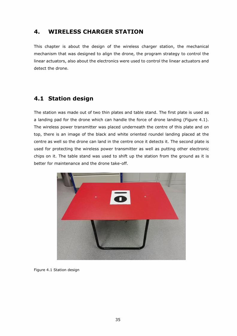
4.1 Station design
The station was made out of two thin plates and table stand. The first plate is used as
a landing pad for the drone which can handle the force of drone landing (Figure 4.1).
The wireless power transmitter was placed underneath the centre of this plate and on
top, there is an image of the black and white oriented roundel landing placed at the
centre as well so the drone can land in the centre once it detects it. The second plate is
used for protecting the wireless power transmitter as well as putting other electronic
chips on it. The table stand was used to shift up the station from the ground as it is
better for maintenance and the drone take-off.
Figure 4.1 Station design

36
4.2 Mechanical alignment mechanism design
The design mechanism which was used in this project can work with AR Parrot drone or
similar drones. As shown in Figure 4.2, the mechanism basically aligns the drone to the
exact centre after landing by pushing it from two sides to the centre and align it to be
symmetric. It basically slides each leg to the centre, once the four legs are being aligned,
the drone is at the centre of the station.
Figure 4.2 Alignment mechanism
4.2.1 Linear actuators
Two different linear actuators were used to align the drone as what was available in the
department. The first one is Hiwin LAM1 which needs an input power of 24 V DC at 6
amps to operate (Figure 4.3).
Figure 4.3 Hiwin LAM1 Linear actuator [28]
The second linear actuator is Qinhuangdao PA-14P, this linear actuator needs an input
of 12 VDC at 1 amp (Figure 4.4).

37
Figure 4.4 Qinhuangdao PA-14P linear actuator [29]
4.3 Steel structure
The station consists of two parts, first, is the table plate and the electronics chips placed
on it. The second part is a structure made out of steel bars to place the linear actuators
on it.
The steel structure design was made out of 10 steel bars all connected together to hold
the thrust force coming from the motors (Figure 4.5). The station is adjustable which
gives the flexibility to move the linear actuators in all directions. This station was built
to host most drones available in the market but, as known that drones have different
shapes and sizes, therefore it can't be aligned by one mechanism.
The solution is to fabricate a different blade suitable for each drone and place it on the
end effector of the linear actuator, this way all drones can be aligned without changing
the station itself.

38
Figure 4.5 Steel structure design
4.4 Station controller
The microcontroller used to control the station is the Arduino Mega 2560. It has enough
number of PWM or digital pins to control the motor drives compared with the other
Arduino boards. This controller had been responsible to control the linear actuation
through the motor drivers and reading the data from the ultrasonic sensor to detect the
drone after landing (Figure 4.6).
Figure 4.6 Arduino Mega 2560 [30]
39
4.5 Motor drivers
To control those two linear actuators using Arduino mega 2560, two H-bridge motor
drivers were used to supply the required voltage and to rotate the motor clockwise and
counter-clockwise because the Arduino controller cannot supply more than 5 V to the
motors.
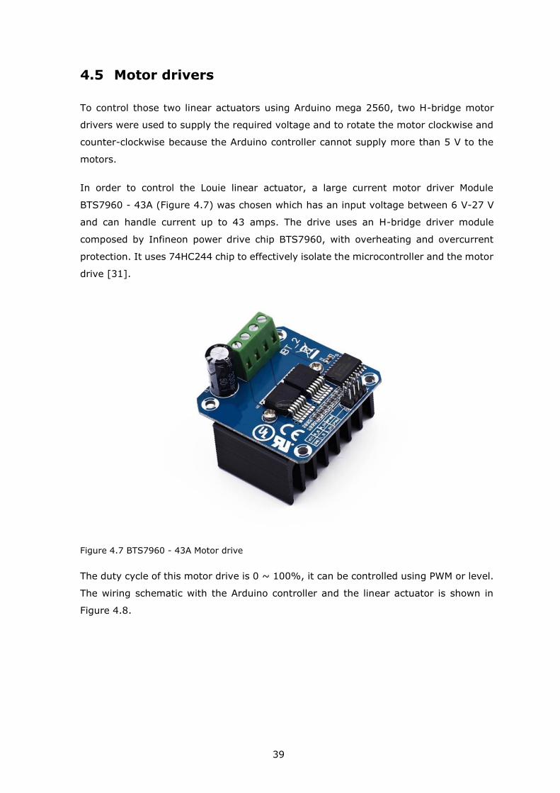
In order to control the Louie linear actuator, a large current motor driver Module
BTS7960 - 43A (Figure 4.7) was chosen which has an input voltage between 6 V-27 V
and can handle current up to 43 amps. The drive uses an H-bridge driver module
composed by Infineon power drive chip BTS7960, with overheating and overcurrent
protection. It uses 74HC244 chip to effectively isolate the microcontroller and the motor
drive [31].
Figure 4.7 BTS7960 - 43A Motor drive
The duty cycle of this motor drive is 0 ~ 100%, it can be controlled using PWM or level.
The wiring schematic with the Arduino controller and the linear actuator is shown in
Figure 4.8.

40
Figure 4.8 BTS7960 - 43A Wiring schematic [32]
The BTS7960 - 43A has 8 control pins as shown in Table 4.1. The RPWM and LPWM Pins
must be connected to a PWM pin on the Arduino, EN pins connected to a digital pin on
the Arduino, the motor driver channel will be disabled if EN pin is low. The ground has
to be unified.
Table 4.1 BTS7960 Control input pin function [33]
Pin No Function Description
1 RPWM Forward Level or PWM signal, Active High
2 LPWM Reverse Level or PWM signal, Active High
3 R_EN Forward Drive Enable Input, Active High/ Low Disable
4 L_EN Reverse Drive Enable Input, Active High/Low Disable
5 R_IS Forward Drive, Side current alarm output
6 L_IS Reverse Drive, Side current alarm output
7 Vcc +5V Power Supply microcontroller
8 Gnd Ground Power Supply microcontroller

41
The chip has another 4 pins for motor output power and power supply input as shown
in Table 4.2.
Table 4.2 BTS7960 Motor power supply and output pin assignment [33]
Pin No Function Description
1 B+ Positive Motor Power Supply. 6 ~ 27VDC
2 B- Negative Motor Power Supply. Ground
3 M+ Motor Output +
4 M- Motor Output -
The motor wires connected to the motor output pins can be switched, which is going to
make a change in the motor voltage polarity only.
The other motor driver chosen to control the Qinhuangdao PA-14P linear actuator is the
L298N (Figure 4.9). This module is a dual H-Bridge motor driver integrated circuit, the
circuit allows easily and independently controlling two motors of up to 2 amps each in
both directions.
Figure 4.9 L298N Motor driver [34]
This chipboard is well suited for making a connection with a microcontroller with few
control lines for each motor. It also can be interfaced with simple logic gates and
switches [35]. The wiring schematic with the Arduino controller and the linear actuator
is shown in Figure 4.10.
42
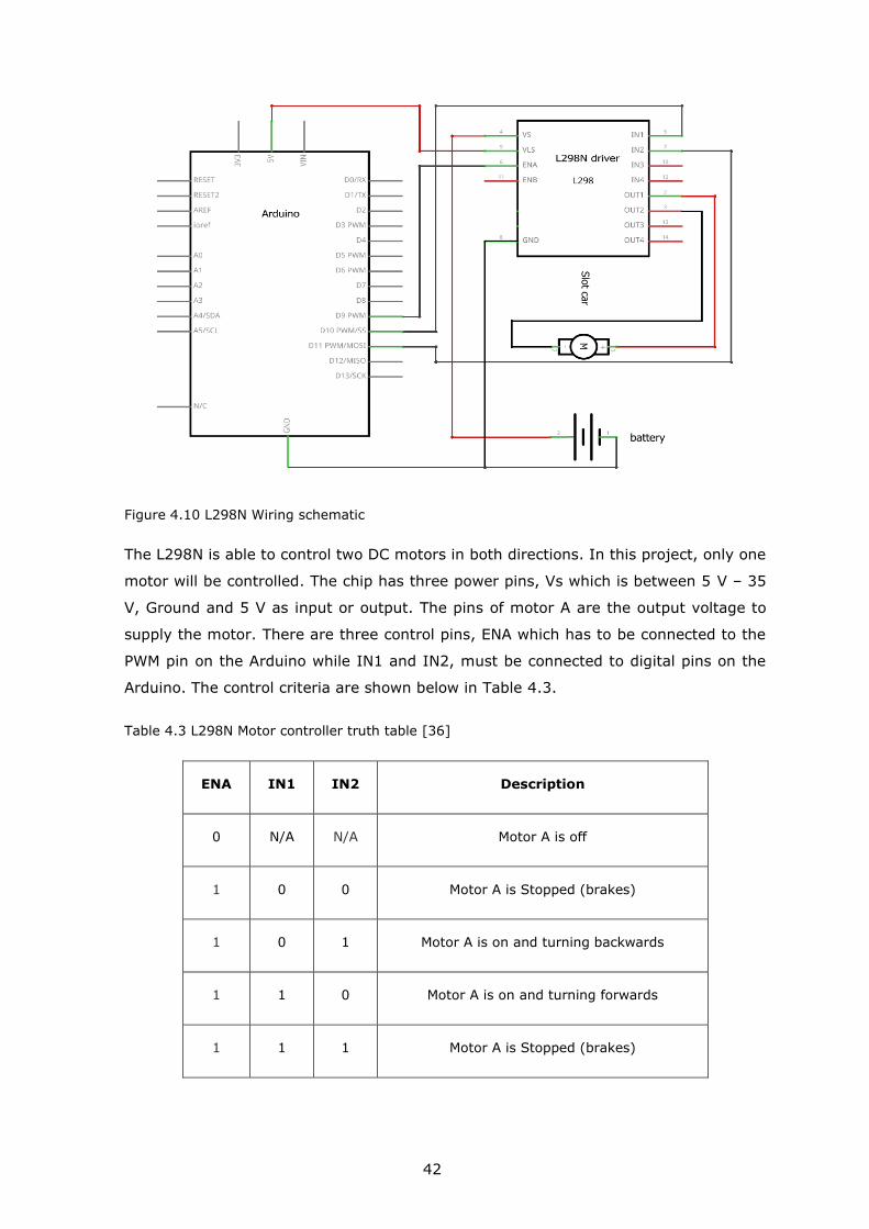
Figure 4.10 L298N Wiring schematic
The L298N is able to control two DC motors in both directions. In this project, only one
motor will be controlled. The chip has three power pins, Vs which is between 5 V – 35
V, Ground and 5 V as input or output. The pins of motor A are the output voltage to
supply the motor. There are three control pins, ENA which has to be connected to the
PWM pin on the Arduino while IN1 and IN2, must be connected to digital pins on the
Arduino. The control criteria are shown below in Table 4.3.
Table 4.3 L298N Motor controller truth table [36]
ENA IN1 IN2 Description
0 N/A N/A Motor A is off
1 0 0 Motor A is Stopped (brakes)
1 0 1 Motor A is on and turning backwards
1 1 0 Motor A is on and turning forwards
1 1 1 Motor A is Stopped (brakes)

43
4.6 Object detection
Detection of the drone on the station will start once it lands on the station, once the
drone is detected, the linear actuators will start moving the drone forward to the centre
then back to its default position to start the wireless charging process.
The sensor used to detect the drone is the ultrasonic SRF05 (Figure 4.11). It can detect
an object up to 4 meters. The sensor was placed at the centre edge of the station top
plate.
Figure 4.11 SRF05 Ultrasonic distance sensor [37]
The ultrasonic sensor measures the distance of the nearest object, sending the result
to the serial port. It can work from 2 cm to 4 m. It measures the time spent by the
signal to reach the object and return to the sensor.
The sensor is going to be controlled by Arduino, measuring distance was adjusted up to
50 cm to detect the drone in the code, the wiring schematic is shown in Figure 4.12.
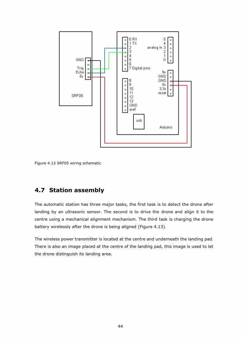
44
Figure 4.12 SRF05 wiring schematic
4.7 Station assembly
The automatic station has three major tasks, the first task is to detect the drone after
landing by an ultrasonic sensor. The second is to drive the drone and align it to the
centre using a mechanical alignment mechanism. The third task is charging the drone
battery wirelessly after the drone is being aligned (Figure 4.13).
The wireless power transmitter is located at the centre and underneath the landing pad.
There is also an image placed at the centre of the landing pad, this image is used to let
the drone distinguish its landing area.

45
Figure 4.13 Automatic station assembly
4.8 Programme flow
As shown in the flow chart in Figure 4.14, the program will start by reading data from
the ultrasonic distance sensor, it will detect the drone after landing to start the
alignment process, once detected, the linear actuators will start moving until they meet
the limit switch, they will stop for 5 seconds then move backwards.
The sensor will keep detecting the drone continuously. To not repeat the same process,
as long as the drone is still detected the controller will not issue new orders. The drone
will take-off when the battery is fully charged, the controller will start from the beginning
then, issuing new orders again if the drone is detected.

46
Figure 4.14 Station programme flowchart

47
This programme has no communication connection with the drone programme at all,
they both work separately in parallel sequence to follow each other. It would be better
to establish communication between them in the future to have more liability on the
system.

48
5. EXPERIMENTAL RESULTS
This chapter covers the experimental results after testing the whole power path starting
from the wireless transmitter to the battery stating the efficiency of the WPT system,
battery charger performance, performance under misalignment, distance issues and
thermal issues.
5.1 Efficiency of the WPT
The efficiency of the WPT can be calculated by measuring the power on the receiver’s
VOUT and GND pins in comparison with the power entering the transmitter. The diagram
below in Figure 5.1, demonstrates that efficiency is a function of output current, and it
runs about 50% at higher power levels, assuring good efficiency and minimal heat
dissipation concerns.
Figure 5.1 Efficiency of Semtech EVM wireless charger at different load current
The peak efficiency of the wireless power transfer system was found to be 83% at 1.2
amps. A comparison made by charging the original battery with its original kit charger
compared with the wireless charger when charging the Turnigy battery. Charging
process was started at 20%, the original battery charger took 50 minutes to reach 100%
while the wireless charger took 60 minutes to reach the same percentage. As the

49
purchased charger would always draw around that range depending on the state of the
battery, it can be ensured that the wireless power transfer would have an efficiency
greater than 83% at all times.
5.2 Performance with the battery charger
The selected battery charger has the option to charge the battery with 1.5 amps.
However, the charging current from the charger likely depends on the state of the
battery. During the experiment, the charger was drawing 1.2 amps regardless of being
powered by a power supply or the WPT system. The power delivered to the charger is
not as high as expected, this is not because of the WPT system but because of the
amount of power drawn by the charger itself and the power loss caused by the step-
down back converter.
To prove that the WPT system can provide more power, a higher capacity battery and
a more sophisticated and heavier battery charger were used. The charger draws a power
of 30 watts to charge a battery at 2 amps rated.
5.3 Performance under misalignment
In order to observe the performance of the system under misalignment, the coils were
freed and put on top of each other. Then, the top coil was moved slightly while fixing
the bottom coil.
The coupling coefficient between the primary coil and the secondary coil, k, was
changing as expected, it becomes significantly weaker as the coils become misaligned.
Furthermore, with changing coupling, the leakage inductances also change. Thus, the
transmitter and receiver capacitance are no longer in resonance with the leakage
inductances. Therefore, the amount of power transferred and efficiency drop with
misalignment.

50
5.4 Performance with vertical distance
The coils were vertically moved away from each other to observe the power and
efficiency characteristics. Similarly, to the misalignment experiment, when the coils are
more than 8 mm apart, the amount of output power and efficiency drop significantly to
0 watts. The distance has to be in the range between 4 mm to 8 mm to transmit and
receive power. Unlike the coil misalignment, the performance with coil separation is not
important for this project. As the drone will always land on the charging station, there
is no need for the charging system to be able to send power through significant vertical
separation.
5.5 Thermal issues
Initially, during testing, the system was unstable due to the voltage regulator that was
getting too hot. The voltage regulator would continue to get hotter with time and the
performance of the system would change with time as well. After putting a heat sink,
the issue of stability was solved. However, the temperature still kept getting hot and
having a large heat sink on the drone is not possible because of the heat it would
produce on the drone and the weight that would affect on the drone.
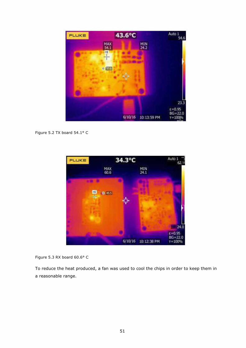
The temperature of TSDMRX-19V20W-EVM under 19 V 20 W condition was given from
the datasheet as shown in Figure 5.2 and Figure 5.3.
51
Figure 5.2 TX board 54.1° C
Figure 5.3 RX board 60.6° C
To reduce the heat produced, a fan was used to cool the chips in order to keep them in
a reasonable range.

52
6. FUTURE WORK
In this chapter of the thesis, a proposes of new solutions or improvements that can be
done to the system in order to make it more efficient and liable.
6.1 Custom made battery charger
One of the main issues is the battery charger. It does not charge at 1.5 amps as stated
on its description. Thus, the battery charger operates at a lower rate even though the
WPT system can provide more power. In order to optimize the drone, a custom battery
charger can be placed on the wireless receiver that has higher input voltage to dispense
with the DC-DC buck converter which is producing a lot of heat, power loss and weight.
The custom-made charger would noticeably reduce the weight and thereby increase the
flight time of the drone.
6.2 Addressing misalignment
Another challenge for the WPT system is the misalignment of the coils. The system is
designed such that the drone lands on the pad after detecting the landing image and
then align it accurately using the mechanical mechanism. However, in case there is
misalignment, the performance deteriorates significantly. Even with small
misalignments, the output voltage of the WPT system falls below the required range of
the battery charger. Consequently, the charging process will not start.
To fix the voltage toleration problem, the battery charger has to be replaced with a wide
operating voltage range battery charger. If the charger could operate from 6 V-19 V as
opposed to 9 V-16 V, it would give much more margin for the coils to be misaligned.
Using a wide operating battery charger would guarantee that the battery will be charged
despite the landing accuracy error.
53
6.3 Linear actuator accuracy
The motors used for the selected linear actuators are normal DC motors. Those motors
can be controlled by PWM or level but, the accuracy of these motors are not sufficient
enough for the mechanical alignment system as they may break the drone in case the
motors moved more than required.
To solve this problem, a stepper linear actuator should be used instead, those motors
move in discrete steps. They have multiple coils that are organized in groups called
"phases". By energizing each phase in sequence, the motor will rotate, one step at a
time [38]. Those motors can achieve very precise positioning.

54
7. CONCLUSION
The project of this thesis has more advantages over the previous projects, it has a fast-
charging process with low cost, the drone can land and charge anytime autonomously
with no need for human interference. It also has the ability to deal with emergency
situations.
The drone was programmed to fly autonomously with being able to detect the charging
station for landing procedure. A fully automatic station was built to align the drone after
landing.
The station can be generalized for most types of drones if there will be suitable blades
fabricated for aligning the drones. The communication protocol used between the power
transmitter and receiver can save energy.
A 40 watts wireless charger was chosen to transfer 16.65 watts to the AR Parrot drone
battery. It can charge a lithium-ion 1500 mAh drone battery under 1.5 hours with a
peak efficiency of 83%. The WPT system is a new step to make more drone applications
fully autonomous.
The start-up company WiBotic announced the "First Autonomous Wireless Charging Pad
for Drones" [39]. This product is quite similar to the idea of this project. However, they
have announced two power levels, low and high, which covers most drones available in
the market and other devices as well. They claim to use "adaptive wireless charging"
technology [40]. Most likely, this technology is a combination of inductive and resonant
wireless charging [41].
Lastly, the WPT system at this power level can be used for other applications and not
only limited to charge drone’s battery. Additionally, the direction of automation field is
making lots of more projects to expand the idea of charging robots, drones and other
devices wirelessly.
Wireless charging systems like this project can support this growth by providing easy
access to automatic charging. It will be interesting to see other applications using the
wireless charger in the future.

55
SUMMARY
This project was assigned to customize a commercially available quad-rotor UAV to
demonstrate an autonomous docking of a quadcopter to an automatic charging station.
The drone must take-off and land autonomously. Once the battery level is below 20%,
it will start the landing procedure on the station. After landing, the station will align the
drone to the centre in order to start the battery charging process. The battery has to be
fully charged in order to take-off again. This means that the drone will have the ability
to charge its battery when needed without any human interference. There are several
ways to solve this problem, with the AR Parrot drone supporting an open-source API
and the charging station having multiple designs to implement.
There were many different approaches that could be used as a charging method. After
studying those methods, it has been decided to use the wireless battery charging as a
method to recharge the battery. It provides very little disadvantage in comparison to
other methods such as conductive and battery swapping. Using the wireless charger,
the station will provide power to the drone once it is docked and aligned to the centre.
The project was aimed to develop an autonomous drone system that can detect the
charging station using image processing and land on it to charge the battery
autonomously. Thus, the project was split into two parts. First was the software design,
which aims to achieve an autonomous flight and docking the drone on the charging
station to start the power charging process wirelessly. To achieve autonomous flight, a
Fantom SDK was used to let the drone control itself. Second, is the hardware design of
the automatic charging station which was responsible to align the drone in the desired
position in order to start recharging its battery in less than 1.5 hours.
The goal of designing a fully autonomous battery charging system was fully met and
experiments were made to test the system’s accuracy. The WPT charging efficiency that
was achieved by the proposed solutions was 83%.

56
KOKKUVÕTE
Selle projekti ülesandeks oli kohandada müügilolevat neljarootorilist UAV-i, et näidata
kvadkopteri autonoomset dokkimist automaatse laadimisjaama juurde. Droon peab
startima ja maanduda autonoomselt. Kui aku tase on alla 20%, alustab see
maandumisprotseduuri jaama. Pärast maandumist joondab jaam drooni aku
laadimisprotsessi alustamiseks keskele. Aku peab uuesti õhku tõusmiseks täielikult
laetud olema. See tähendab, et droonil on võimalus oma akut vajadusel laadida ilma
inimese sekkumiseta. Selle probleemi lahendamiseks on mitu viisi, kuna AR Parroti
droon toetab avatud lähtekoodiga API-d ja laadimisjaamal on mitu konstruktsiooni, mida
rakendada.
Laadimismeetodina oli palju erinevaid lähenemisviise. Pärast nende meetodite uurimist
otsustati kasutada aku laadimiseks juhtmevaba meetodit. Võrreldes teiste meetoditega,
nagu juhtivlaadimine ja aku vahetamine, on sel meetodil vähe halbu omadusi. Traadita
laadijat kasutades annab jaam droonile toite, kui see on dokitud ja keskele joondatud.
Projekti eesmärk oli välja töötada autonoomne droonisüsteem, mis suudaks
pilditöötluse abil laadimisjaama tuvastada ja maanduda sellele aku autonoomseks
laadimiseks. Seega jagunes projekt kaheks osaks. Esiteks oli tarkvara kujundamine,
mille eesmärk on saavutada autonoomne lend ja drooni maandumine laadimisjaama, et
käivitada elektrienergia laadimise protsess juhtmevabalt. Autonoomse lennu
saavutamiseks kasutati Fantom SDK-d, mis lasi droonil ennast juhtida. Teiseks on
automaatse laadimisjaama riistvarakujundus, mille ülesandeks oli drooni soovitud
asendisse viimine, et alustada aku laadimist vähem kui 1.5 tunni pärast.
Täielikult autonoomse akulaadimise süsteemi kujundamise eesmärk saavutati täielikult
ja süsteemi täpsuse testimiseks tehti katseid. Pakutavate lahendustega saavutatud
WPT-laadimise efektiivsus oli 83%.

57
LIST OF REFERENCES
[1] “FAA Aerospace Forecast,” 2016. [Online]. Available:
https://www.faa.gov/data_research/aviation/aerospace_forecasts/media/FY201
6-36_FAA_Aerospace_Forecast.pdf. [Accessed: 11-Mar-2020].
[2] “Drone Light Shows Powered by Intel.” [Online]. Available:
https://www.intel.com/content/www/us/en/technology-innovation/aerial-
technology-light-show.html?spredfast-trk-id=sf194249547. [Accessed: 11-Mar-
2020].
[3] D. Floreano and R. J. Wood, “Science, technology and the future of small
autonomous drones,” Nature, vol. 521, no. 7553. Nature Publishing Group, pp.
460–466, 27-May-2015, doi: 10.1038/nature14542.
[4] “Top 10 Drones with Longest Flight Time for 2020.” [Online]. Available:
https://filmora.wondershare.com/drones/drones-with-longest-flight-time.html.
[Accessed: 11-Mar-2020].
[5] “Autonomous Battery Charging of Quad-copter.” [Online]. Available:
https://ecesd.engr.uconn.edu/ecesd1722/files/2016/12/ECE4901FinalReport.pdf
. [Accessed: 10-Apr-2020].
[6] “University of Connecticut - Autonoumous station.” [Online]. Available:
https://ecesd.engr.uconn.edu/ecesd1722/files/2016/12/Team1722_ECE4902Fin
alReportPDF.pdf. [Accessed: 10-Apr-2020].
[7] “‘The Transmission of Electrical Energy Without Wires as a Means for Furthering
Peace’ by Nikola Tesla.” [Online]. Available:
http://www.tfcbooks.com/tesla/1905-01-07.htm. [Accessed: 10-Apr-2020].
[8] “Inductive charging - Wikipedia.” [Online]. Available:
https://en.wikipedia.org/wiki/Inductive_charging. [Accessed: 10-Apr-2020].
[9] C. Chang, C. Monstein, A. Refregier, A. Amara, A. Glauser, and S. Casura, “Beam
Calibration of Radio Telescopes with Drones,” 2015.
[10] P. Chang Woo and C. Hee Tae, “A Study on Drone Charging System Using Wireless
Power Transmission.” [Online]. Available:
https://pdfs.semanticscholar.org/b7e4/708733c78cb05771d71cb4c5626af2764a
12.pdf. [Accessed: 22-Apr-2020].
58
[11] “Enhancing the Proficiency of the Drone with an Application of Ocean Farming.”
[Online]. Available:
https://www.researchgate.net/publication/326537443_Enhancing_the_Proficien
cy_of_the_Drone_with_an_Application_of_Ocean_Farming/link/5e598b7d299bf1
bdb8443fff/download. [Accessed: 10-Apr-2020].
[12] “Drone Charging Stations - Humavox.” [Online]. Available:
http://www.humavox.com/blog/drone-charging-stations-whats-the-best-way-
to-charge-your-drone/. [Accessed: 11-Apr-2020].
[13] “EAGLE EYE Is the Drone that Just Might Save Your Life | American Luxury.”
[Online]. Available: https://www.amlu.com/2017/06/09/eagle-eye-is-the-drone-
that-just-might-save-your-life/. [Accessed: 12-Apr-2020].
[14] “WhyFantom – Fantom.” [Online]. Available:
https://fantom.org/doc/docIntro/WhyFantom. [Accessed: 11-Mar-2020].
[15] “Quadcopter AR Drone 2.0 Elite Edition | Parrot Official.” [Online]. Available:
https://www.parrot.com/global/drones/parrot-ardrone-20-elite-edition.
[Accessed: 11-Mar-2020].
[16] “Black and White Oriented Roundel.” [Online]. Available:
https://github.com/SlimerDude/afParrotSdk2/tree/master/dev. [Accessed: 11-
Mar-2020].
[17] “HD Battery for AR.Drone 2.0 | Parrot Store Official.” [Online]. Available:
https://www.parrot.com/be/spareparts/drones/hd-battery-ardrone-20.
[Accessed: 12-Mar-2020].
[18] “Parrot AR. Drone 2.0 HD Battery | at Mighty Ape NZ.” [Online]. Available:
https://www.mightyape.co.nz/product/parrot-ar-drone-2-0-hd-
battery/23011189. [Accessed: 12-Mar-2020].
[19] “Turnigy 1500mAh 3S 20C Lipo Pack.” [Online]. Available:
https://hobbyking.com/en_us/turnigy-1500mah-3s-20c-lipo-pack.html.
[Accessed: 12-Mar-2020].
[20] “Salesforce.” [Online]. Available:
https://semtech.my.salesforce.com/sfc/p/#E0000000JelG/a/2R0000001O3S/xf
WFD.BPthhjoNz9ljHIjYUAH1n4p8QVJeE7yRENjxI. [Accessed: 24-Mar-2020].
[21] “40W Wireless Charging Solution | Semtech.” [Online]. Available:

59
https://www.semtech.com/products/wireless-charging/linkcharge-high-power-
evms/lkch-txrx40w-evb. [Accessed: 25-Mar-2020].
[22] “TSDMTX-19V2-EVM Semtech | Mouser South Africa.” [Online]. Available:
https://www.mouser.co.za/ProductDetail/Semtech/TSDMTX-19V2-
EVM?qs=LlUlMxKIyB3LzTkWEMHZQw%3D%3D. [Accessed: 25-Mar-2020].
[23] “TSDMRX-19V-20W-EVM Semtech Corporation | Development Boards, Kits,
Programmers | DigiKey.” [Online]. Available: https://www.digikey.ee/product-
detail/en/semtech-corporation/TSDMRX-19V-20W-EVM/TSDMRX-19V-20W-EVM-
ND/6569371. [Accessed: 25-Mar-2020].
[24] “Hobbyking® DC-4S Balance Charger & Cell Checker 30w 2s~4s.” [Online].
Available: https://hobbyking.com/en_us/hobbykingr-dc-4s-balance-charger-
cell-checker-30w-2s-4s.html?___store=en_us. [Accessed: 26-Mar-2020].
[25] “Charsoon DC-4S 2-4S Li-poly/Li-ion Battery Balance Charger & Voltage Detector
with Power Adapter for RC Drone – Mister SmartDeal.” [Online]. Available:
https://mistersmartdeal.com/product/charsoon-dc-4s-2-4s-li-poly-li-ion-
battery-balance-charger-voltage-detector-with-power-adapter-for-rc-drone/.
[Accessed: 26-Mar-2020].
[26] “Circuit: Voltage Divider.” [Online]. Available:
https://physics.eou.edu/courses/phys_223/sg2/node5.html. [Accessed: 26-Mar-
2020].
[27] “LM2596 DC-DC Buck Converter Step-Down Power Module Output 1.25V-35V.”
[Online]. Available: https://www.itead.cc/lm2596-dc-dc-buck-converter-step-
down-power-module-output-1-25v-35v.html. [Accessed: 26-Mar-2020].
[28] “Linear Actuators- Huntley, Illinois- HIWIN Corporation.” [Online]. Available:
https://www.hiwin.com/linear-actuators.html. [Accessed: 29-Apr-2020].
[29] “Electric Linear Actuator 12v24VDC Motor 1000mm Stroke Linear Motion
Controller 5mm/s-20mm/s thrust 700N-1500N Lift for Electric - aliexpress.com -
imall.com.” [Online]. Available: https://imall.com/product/Electric-Linear-
Actuator-12v24VDC-Motor-1000mm-Stroke-Motion-Controller-5mm-s-20mm-
thrust-700N-1500N-Lift-for/Home-Improvement-Electrical-Equipments-
Supplies-Motors-Parts-DC/aliexpress.com/32870037424/567-30701009/ru.
[Accessed: 29-Apr-2020].

60
[30] “Arduino Mega 2560 Rev3 | Arduino Official Store.” [Online]. Available:
https://store.arduino.cc/arduino-mega-2560-rev3. [Accessed: 13-Apr-2020].
[31] “Large Current Motor Driver Module BTS7960 - 43A - ITT Group (robolabor.ee).”
[Online]. Available: https://www.ittgroup.ee/en/drivers/731-large-current-
motor-driver-module-bts7960-
43a.html?search_query=motor+drive&results=189. [Accessed: 01-Apr-2020].
[32] “[Solved ] BTS7960 based H-Bridge (IBT_2) behaviing strangely.” [Online].
Available: https://forum.arduino.cc/index.php?topic=338661.0. [Accessed: 02-
Apr-2020].
[33] “Handson Technology User Guide BTS7960.” [Online]. Available:
https://www.handsontec.com/dataspecs/module/BTS7960 Motor Driver.pdf.
[Accessed: 02-Apr-2020].
[34] “Motor Driver L298N - ITT Group (robolabor.ee).” [Online]. Available:
https://www.ittgroup.ee/en/drivers/265-motor-driver-
l298n.html?search_query=motor+drive&results=189. [Accessed: 02-Apr-2020].
[35] “L298N Dual H-Bridge Motor Driver.” [Online]. Available:
http://www.handsontec.com/dataspecs/L298N Motor Driver.pdf. [Accessed: 03-
Apr-2020].
[36] “How to Program the L298N with Arduino - Learn Robotics.” [Online]. Available:
https://www.learnrobotics.org/blog/how-to-program-the-l298n-with-arduino/.
[Accessed: 03-Apr-2020].
[37] “Ultrasonic Distance Sensor (HY-SRF05) – Pi Supply.” [Online]. Available:
https://uk.pi-supply.com/products/ultrasonic-distance-sensor-hy-srf05.
[Accessed: 03-Apr-2020].
[38] “What is a Stepper Motor? | All About Stepper Motors | Adafruit Learning System.”
[Online]. Available: https://learn.adafruit.com/all-about-stepper-motors.
[Accessed: 08-Apr-2020].
[39] “WiBotic Announces WiBotic PowerPad, the First Autonomous Wireless Charging
Pad for Drones | WiBotic.” [Online]. Available: https://www.wibotic.com/news-
releases/wibotic-announces-wibotic-powerpad-first-autonomous-wireless-
charging-pad-drones/. [Accessed: 09-Apr-2020].

61
[40] “Technology | WiBotic.” [Online]. Available:
https://www.wibotic.com/technology/. [Accessed: 09-Apr-2020].
[41] “Robolliance Features WiBotic Cutting the Cord with Wireless Charging | WiBotic.”
[Online]. Available: https://www.wibotic.com/robolliance-features-wibotic-
cutting-cord-wireless-charging/. [Accessed: 09-Apr-2020].
62
APPENDICES
Appendix 1
Fantom code for autonomous flight:
using afParrotSdk2
using fwt::Desktop
using fwt::Label
using fwt::Window
using gfx::Color
using gfx::Font
using gfx::Size
using concurrent::Actor
using concurrent::ActorPool
** Uses the Drone's onNavData event to display basic telemetry data.
class NavDataExample {
Drone? drone
Label? screen
Void main() {
thisRef := Unsafe(this)
drone = Drone()
drone.onNavData = |NavData navData| {
// ensure that UI stuff (e.g. printing window text) is done in the UI thread
Desktop.callAsync |->| {
thisRef.val->printNavData(navData)

63
}
}
drone.onDisconnect = |Bool abnormal| {
Desktop.callAsync |->| {
thisRef.val->screen->text = "*** Disconnected ***"
}
}
Window {
it.title = "Parrot SDK 2.0 - NavData Demo"
it.size = Size(440, 300)
it.onOpen.add |->| {
// fly drone in it's own thread
Actor(ActorPool()) |->| { thisRef.val->fly }.send(null)
}
it.onClose.add |->| {
drone.disconnect
}
it.add(
screen = Label {
it.font = Font { name = "Consolas"; size = 10}
it.bg = Color(0x202020)
it.fg = Color(0x31E722)
it.text = "Connecting to Drone..."

64
}
)
}.open
}
Void fly() {
drone.connect
drone.config.session("demo")
drone.config.session.videoCamera = VideoCamera.vertical
drone.config.session.videoResolution = VideoResolution._720p
drone.config.session.app.navDataOptions = NavOption.demo.flag +
NavOption.visionDetect.flag
drone.config.session.detectRoundel = VideoCamera.vertical
drone.flatTrim
Actor.sleep(2sec)
drone.takeOff
Actor.sleep(2sec)
}
Void printNavData(NavData navData) {
if (navData.demoData == null) return
buf := StrBuf(1024 * 2).addChar('\n')
flags := navData.flags
data := navData.demoData
title := "Fantom Drone SDK Demo".justr(maxWidth - 10)
credit := "by Alien-Factory".justr(maxWidth - 10)

65
text := "Connected to Drone v${drone.droneVersion}".justr(maxWidth - 10)
buf.addChar('\n')
status := "Flight Status: ${drone.flightState.name.toDisplayName}"
battery := "Battery Level: ${data.batteryPercentage}%"
pad := "".justr(maxWidth - status.size - battery.size)
buf.add(status).add(pad).add(battery).addChar('\n')
data1 := (Str:Obj) drone.navData[NavOption.visionDetect]
if (data.batteryPercentage == 100) {
drone.takeOff
}
if (data.batteryPercentage < 20) {
if (data1["nbDetected"] > 0) {
drone.moveDown(0.1f,8sec)
drone.land
}}
buf.addChar('\n')
buf.add("Altitude : " + data.altitude.toLocale("0.00") + " m").addChar('\n')
buf.add("Orientation: ")
printNum(buf, "X", data.phi)
printNum(buf, "Y", data.theta)
printNum(buf, "Z", data.psi)
buf.addChar('\n')
buf.add("Velocity : ")

66
printNum(buf, "X", data.velocityX)
printNum(buf, "Y", data.velocityY)
printNum(buf, "Z", data.velocityZ)
buf.addChar('\n')
buf.addChar('\n')
buf.add(centre(flags.flying ? "--- Flying ---" : "")).addChar('\n')
emer := flags.emergencyLanding ? "*** EMERGENCY ***" : ""
emer = flags.userEmergencyLanding ? "*** USER EMERGENCY ***" : emer
buf.add(centre(emer)).addChar('\n')
buf.add(centre(flags.batteryTooLow ? "*** BATTERY LOW ***" :
"")).addChar('\n')
[NavDataFlags#motorProblem,
NavDataFlags#gyrometersDown,
NavDataFlags#magnometerNeedsCalibration,
NavDataFlags#anglesOutOufRange,
NavDataFlags#tooMuchWind,
NavDataFlags#ultrasonicSensorDeaf,
NavDataFlags#cutOutDetected].each {
if (it.call(flags) == true)
buf.add(centre("!!! ${it.name.toDisplayName} !!!")).addChar('\n')
}
screen.text = buf.toStr
}
Void printNum(StrBuf buf, Str str, Float num) {

67
buf.add("[").add(str).add("]")
buf.add(num.toLocale("0.00").justr(7))
buf.add(" ")
}
Str centre(Str txt) {
("".justr((maxWidth - txt.size) / 2) + txt).justl(maxWidth)
}
Int maxWidth() { (screen.bounds.w / screen.font.width("W") - 2).max(48) }}
68
Appendix 2
Arduino code for an automatic charging station:
/* This is the Arduino code BTS7960 DC motor Driver
Using this code you can control a motor to rotate in both direction Clockwise(CW)
and Counter-clockwise(CCW)
#define RPWM 3 // define pin 3 for RPWM pin (output)
#define R_EN 4 // define pin 2 for R_EN pin (input)
#define R_IS 5 // define pin 5 for R_IS pin (output)
#define LPWM 6 // define pin 6 for LPWM pin (output)
#define L_EN 7 // define pin 7 for L_EN pin (input)
#define L_IS 8 // define pin 8 for L_IS pin (output)
#define CW 1 //do not change
#define CCW 0 //do not change
#define debug 1 //change to 0 to hide serial monitor debugging infornmation or set to
1 to view
// defines pins numbers
const int trigPin = 11;
const int echoPin = 12;
// defines variables
long duration;
int distance;
int In1 = 9;
int In2 = 10;

69
int ENA = 2;
int SPEED;
#include <RobojaxBTS7960.h>
RobojaxBTS7960 motor(R_EN,RPWM,R_IS, L_EN,LPWM,L_IS,debug);
void setup() {
pinMode(In1, OUTPUT);
pinMode(In2, OUTPUT);
pinMode(ENA, OUTPUT);
pinMode(trigPin, OUTPUT); // Sets the trigPin as an Output
pinMode(echoPin, INPUT);// Sets the echoPin as an Input
// BTS7960 Motor Control Code by Robojax.com 20190622
Serial.begin(9600);// setup Serial Monitor to display information
motor.begin();
}
void loop() {
delay(1);
// Clears the trigPin
digitalWrite(trigPin, LOW);
delayMicroseconds(2);
// Sets the trigPin on HIGH state for 10 micro seconds
digitalWrite(trigPin, HIGH);
delayMicroseconds(10);
digitalWrite(trigPin, LOW);

70
// Reads the echoPin, returns the sound wave travel time in microseconds
duration = pulseIn(echoPin, HIGH);
// Calculating the distance
distance= duration*0.034/2;
if(distance < 30){
delay(3000);// time to stop the motors
motor.rotate(50,CW);// run motor at 50% speed in CCW direction
digitalWrite(In1, LOW);
digitalWrite(In2, HIGH);
digitalWrite(ENA, 64);
delay(8000);// run for 8 seconds
motor.stop();// stop the motor
digitalWrite(ENA, 0);
motor.rotate(50,CW);// run motor at 50% speed in CCW direction
delay(25000);
motor.stop();// stop the motor
delay(10000);
// BTS7960 Motor Control Code by Robojax.com 20190622
motor.rotate(50,CCW);// run motor with 50% speed in CW direction
delay(33525);
motor.stop();// stop the motor
digitalWrite(In1, HIGH);

71
digitalWrite(In2, LOW);
digitalWrite(ENA, 64);
delay(8400);
digitalWrite(ENA, 0);
delay(2000);// stop for 2 seconds
while (distance < 30){
motor.stop();// stop the motor
digitalWrite(trigPin, LOW);
delayMicroseconds(2);
// Sets the trigPin on HIGH state for 10 micro seconds
digitalWrite(trigPin, HIGH);
delayMicroseconds(10);
digitalWrite(trigPin, LOW);
// Reads the echoPin, returns the sound wave travel time in microseconds
duration = pulseIn(echoPin, HIGH);
// Calculating the distance
distance= duration*0.034/2;
delay(2000);
}}}// loop ends