Road User Charging: Acceptability and Effectiveness - White ...
Upload
khangminh22Category
view
0download
0
SC-1
STARTING & CHARGING SYSTEM
K ELECTRICAL
CONTENTS
C
D
E
F
G
H
I
J
L
M
SECTION SCA
B
SC
Revision: March 2005 2005 Altima
PRECAUTIONS .......................................................... 2Precautions for Supplemental Restraint System (SRS) “AIR BAG” and “SEAT BELT PRE-TEN-SIONER” .................................................................. 2Wiring Diagrams and Trouble Diagnosis .................. 2
PREPARATION ........................................................... 3Special Service Tool ................................................. 3Commercial Service Tools ........................................ 3
BATTERY .................................................................... 4How to Handle Battery ............................................. 4
METHODS OF PREVENTING OVER-DIS-CHARGE ............................................................... 4CHECKING ELECTROLYTE LEVEL .................... 4SPECIFIC GRAVITY CHECK ............................... 5CHARGING THE BATTERY ................................. 6
Trouble Diagnoses with Battery/Starting/Charging System Tester .......................................................... 6
DIAGNOSTIC RESULT ITEM CHART .................. 8STARTING SYSTEM .................................................. 9
System Description .................................................. 9M/T MODELS ........................................................ 9A/T MODELS ........................................................ 9
CAN Communication System Description ................ 9Wiring Diagram — START — ................................. 10
M/T MODELS ...................................................... 104 A/T MODEL .......................................................115 A/T MODEL ...................................................... 12
Trouble Diagnoses with Battery/Starting/Charging System Tester ........................................................ 13
DIAGNOSTIC RESULT ITEM CHART ................ 13WORK FLOW ...................................................... 14
DIAGNOSTIC PROCEDURE 1 ........................... 15DIAGNOSTIC PROCEDURE 2 ........................... 16MINIMUM SPECIFICATION OF CRANKING VOLTAGE REFERENCING COOLANT TEM-PERATURE ......................................................... 17
Removal and Installation ........................................ 17M/T MODELS ...................................................... 17
Removal and Installation ........................................ 174-SPEED A/T MODELS ...................................... 17
Removal and Installation ........................................ 185-SPEED A/T MODELS ...................................... 18
Pinion/Clutch Check ............................................... 20CHARGING SYSTEM ............................................... 21
System Description ................................................. 21Wiring Diagram — CHARGE — ............................. 22Trouble Diagnoses with Battery/Starting/Charging System Tester ......................................................... 23
DIAGNOSTIC RESULT ITEM CHART ................ 24WORK FLOW ...................................................... 25DIAGNOSTIC PROCEDURE 1 ........................... 26DIAGNOSTIC PROCEDURE 2 ........................... 27DIAGNOSTIC PROCEDURE 3 ........................... 28MALFUNCTION INDICATOR .............................. 29
Removal and Installation ........................................ 29QR25DE .............................................................. 29VQ35DE .............................................................. 29
SERVICE DATA AND SPECIFICATIONS (SDS) ...... 31Battery .................................................................... 31Starter ..................................................................... 31Generator ............................................................... 31

SC-2
PRECAUTIONS
Revision: March 2005 2005 Altima
PRECAUTIONS PFP:00001
Precautions for Supplemental Restraint System (SRS) “AIR BAG” and “SEAT BELT PRE-TENSIONER” EKS008KU
The Supplemental Restraint System such as “AIR BAG” and “SEAT BELT PRE-TENSIONER”, used alongwith a front seat belt, helps to reduce the risk or severity of injury to the driver and front passenger for certaintypes of collision. This system includes seat belt switch inputs and dual stage front air bag modules. The SRSsystem uses the seat belt switches to determine the front air bag deployment, and may only deploy one frontair bag, depending on the severity of a collision and whether the front occupants are belted or unbelted.Information necessary to service the system safely is included in the SRS and SB section of this Service Man-ual.WARNING:● To avoid rendering the SRS inoperative, which could increase the risk of personal injury or death
in the event of a collision which would result in air bag inflation, all maintenance must be per-formed by an authorized NISSAN/INFINITI dealer.
● Improper maintenance, including incorrect removal and installation of the SRS, can lead to per-sonal injury caused by unintentional activation of the system. For removal of Spiral Cable and AirBag Module, see the SRS section.
● Do not use electrical test equipment on any circuit related to the SRS unless instructed to in thisService Manual. SRS wiring harnesses can be identified by yellow and/or orange harnesses orharness connectors.
Wiring Diagrams and Trouble Diagnosis EKS008KV
When you read wiring diagrams, refer to the following: ● GI-14, "How to Read Wiring Diagrams" .● PG-4, "POWER SUPPLY ROUTING CIRCUIT" for power distribution circuit.When you perform trouble diagnosis, refer to the following:● GI-10, "HOW TO FOLLOW TEST GROUPS IN TROUBLE DIAGNOSES".● GI-26, "How to Perform Efficient Diagnosis for an Electrical Incident".

PREPARATION
SC-3
C
D
E
F
G
H
I
J
L
M
A
B
SC
Revision: March 2005 2005 Altima
PREPARATION PFP:00002
Special Service Tool EKS008KW
Commercial Service Tools EKS008KX
Tool numberTool name
Description
J-44373 Model 620Battery/Starting/Charging system tester
SEL403X
Tool numberTool name
Description
Power tool Loosening bolts and nuts
PBIC0190E

SC-4
BATTERY
Revision: March 2005 2005 Altima
BATTERY PFP:AYBGL
How to Handle Battery EKS008KY
CAUTION:● If it becomes necessary to start the engine with a booster battery and jumper cables, use a 12-volt
booster battery.● After connecting battery cables, ensure that they are tightly clamped to battery terminals for good
contact.● Never add distilled water through the hole used to check specific gravity.
METHODS OF PREVENTING OVER-DISCHARGEThe following precautions must be taken to prevent over-discharginga battery.● The battery surface (particularly its top) should always be kept
clean and dry.● The terminal connections should be clean and tight.● At every routine maintenance, check the electrolyte level.
This also applies to batteries designated as “low maintenance”and “maintenance-free”.
● When the vehicle is not going to be used over a long period oftime, disconnect the negative battery terminal.
● Check the charge condition of the battery.Periodically check the specific gravity of the electrolyte. Keep aclose check on charge condition to prevent over-discharge.
CHECKING ELECTROLYTE LEVELWARNING:Do not allow battery fluid to come in contact with skin, eyes, fabrics, or painted surfaces. After touch-ing a battery, do not touch or rub your eyes until you have thoroughly washed your hands. If acid con-tacts eyes, skin or clothing, immediately flush with water for 15 minutes and seek medical attention.
MEL040F
MEL041F
MEL042F

BATTERY
SC-5
C
D
E
F
G
H
I
J
L
M
A
B
SC
Revision: March 2005 2005 Altima
● Remove the cell plug using a suitable tool.● Add distilled water up to the MAX level.
SulphationA battery will be completely discharged if it is left unattendedfor a long time and the specific gravity will become less than1.100. This may result in sulphation on the cell plates.To determine if a battery has been “sulphated”, note its voltageand current when charging it. As shown in the figure, less cur-rent and higher voltage are observed in the initial stage ofcharging sulphated batteries.A sulphated battery may sometimes be brought back into ser-vice by means of a long, slow charge, 12 hours or more, fol-lowed by a battery capacity test.
SPECIFIC GRAVITY CHECK1. Read hydrometer and thermometer indications at eye level.2. Use the following chart to correct your hydrometer reading
according to electrolyte temperature.
Hydrometer Temperature Correction
MEL043F
SEL709E
MEL042FA
Battery electrolyte temperature °C (°F) Add to specific gravity reading
71 (160) 0.032
66 (150) 0.028
60 (140) 0.024
54 (130) 0.020
49 (120) 0.016
43 (110) 0.012
38 (100) 0.008
32 (90) 0.004
27 (80) 0
21 (70) −0.004
16 (60) −0.008
10 (50) −0.012
4 (40) −0.016
−1 (30) −0.020
−7 (20) −0.024

SC-6
BATTERY
Revision: March 2005 2005 Altima
CHARGING THE BATTERYCAUTION:● Do not “quick charge” a fully discharged battery.● Keep the battery away from open flame while it is being charged.● When connecting the charger, connect the leads first, then turn on the charger. Do not turn on the
charger first, as this may cause a spark.● If battery electrolyte temperature rises above 60°C (140°F), stop charging. Always charge battery
at a temperature below 60°C (140°F).
Charging Rates
Do not charge at more than 50 ampere rate.NOTE:The ammeter reading on your battery charger will automatically decrease as the battery charges. This indi-cates that the voltage of the battery is increasing normally as the state of charge improves. The charging ampsindicated above refer to initial charge rate.● If, after charging, the specific gravity of any two cells varies more than .050, the battery should be
replaced.
Trouble Diagnoses with Battery/Starting/Charging System Tester EKS008KZ
CAUTION:When working with batteries, always wear appropriate eye protection.NOTE:● To ensure a complete and thorough diagnosis, the battery, starter and generator test segments must be
done as a set from start to finish.● If battery surface charge is detected while testing, the tester will prompt you to turn on the headlights to
remove the surface charge.● If necessary, the tester will prompt you to determine if the battery temperature is above or below 0°C
(32°F). Choose the appropriate selection by pressing the up or down arrow button, then press “ENTER” tomake the selection.
−12 (10) −0.028
−18 (0) −0.032
Corrected specific gravity Approximate charge condition
1.260 - 1.280 Fully charged
1.230 - 1.250 3/4 charged
1.200 - 1.220 1/2 charged
1.170 - 1.190 1/4 charged
1.140 - 1.160 Almost discharged
1.110 - 1.130 Completely discharged
Battery electrolyte temperature °C (°F) Add to specific gravity reading
Amps Time
50 1 hour
25 2 hours
10 5 hours
5 10 hours
BATTERY
SC-7
C
D
E
F
G
H
I
J
L
M
A
B
SC
Revision: March 2005 2005 Altima
1. Turn off all loads on the vehicle electrical system. Clean or repairas necessary.
2. Visually inspect the battery, battery terminals and cable endswith ignition switch in “OFF” position.NOTE:The contact surface between the battery terminals, cable endsand tester leads must be clean for a valid test. A poor connec-tion will prevent testing and a “CHECK CONNECTION” mes-sage will appear during the test procedures. If this occurs, cleanthe battery post and terminals, reconnect them and restart thetest.
3. Connect the red tester lead clamp to the positive battery termi-nal, and the black to the negative terminal.
4. The tester will turn on automatically. Using the arrow keys,select “IN-VEHICLE” on the tester and then press the “ENTER”key.
5. Locate the battery type and rating stamped or written on the topcase of the battery to be tested.NOTE:The battery type and rating will have either of the following.CCA: Cold Cranking Amps (490 CCA, 550 CCA, etc.)JIS: Japanese Industrial Standard.Battery is stamped with a number such as:80D26L: 80 (rank of output), D (physical size-depth), 26 (widthin cm). The last character L (post configuration) is not input intothe tester.The tester requires the rating for the battery be entered exactlyas it is written or stamped on the battery. Do not attempt a CCAconversion for JIS stamped batteries. JIS must be input directly.
6. Using the arrow and “ENTER” keys alternately, select the battery type and rating.NOTE:The tester lists five choices; CCA, JIS, IEC, DIN, and EN. Only use CCA or JIS.
7. Press “ENTER” to begin the test. Diagnosis results are dis-played on the tester. Refer to SC-8, "DIAGNOSTIC RESULTITEM CHART" .
SEL404X
SEL405X
SEL406X
SEL407X

SC-8
BATTERY
Revision: March 2005 2005 Altima
8. Press “ENTER”, then test output code is displayed. Record thetest output code on the repair order.
9. Toggle back to the “DIAGNOSTIC SCREEN” for test results.NOTE:● If necessary, the tester will ask the user to determine if the
battery has just been charged. Choose the appropriate selec-tion by pressing the up or down arrow button and then pressthe “ENTER” button to make the selection.
● When testing a battery installed in a vehicle that has recentlybeen driven, select “BEFORE CHARGE”.
● If the battery has just been slow charged due to a “CHARGE& RETEST” decision by the tester, and the tester asks the user “BEFORE CHARGE/AFTERCHARGE”, select “AFTER CHARGE”.
DIAGNOSTIC RESULT ITEM CHART
SEL576X
Diagnostic item Service procedure
GOOD BATTERYBattery is OK. Refer to SC-13, "Trouble Diagnoses with Battery/Starting/Charging System Tester" .
REPLACE BATTERY
Replace battery.Before replacing battery, clean the battery cable clamps and battery posts. Perform battery test again with Battery/Starting/Charging system tester. If second test result is “Replace Bat-tery”, then do so. Perform battery test again to confirm repair.
BAD CELL-REPLACEReplace the battery. Perform battery test again with Battery/Starting/Charging system tester to confirm repair.
GOOD-RECHARGEPerform the slow battery charging procedure. (Initial rate of charge is 10A for 12 hours.) Per-form battery test again with Battery/Starting/Charging system tester.
CHARGE & RETEST
Perform the slow battery charging. (Initial rate of charge is 10A for 12 hours.)Perform battery test again with Battery/Starting/Charging system tester to confirm repair.
NOTE:If the tester asks the user “BEFORE CHARGE/AFTER CHARGE”, select “AFTER CHARGE”.

STARTING SYSTEM
SC-9
C
D
E
F
G
H
I
J
L
M
A
B
SC
Revision: March 2005 2005 Altima
STARTING SYSTEM PFP:23300
System Description EKS008L0
M/T MODELSPower is supplied at all times:● through 40A fusible link (letter m , located in the fuse and fusible link box)● to ignition switch terminal B.With the ignition switch in the START position, power is supplied:● from ignition switch terminal ST● to intelligent power distribution module engine room (IPDM E/R) terminal 4.With the ignition switch in the ON or START position, power is supplied:● through 10A fuse [No. 12, located in the fuse block (J/B)]● to IPDM E/R terminal 53.When the clutch pedal is depressed, ground is supplied to IPDM E/R terminal 50 through the clutch interlockswitch and body grounds E15 and E24.Provided that the IPDM E/R receives a starter relay request ON signal from the BCM over the CAN lines, theIPDM E/R grounds the starter relay and power is supplied:● from terminal 3 of the IPDM E/R● to terminal S of the starter motor windings.The starter motor plunger closes and provides a closed circuit between the battery and the starter motor. Thestarter motor is grounded to the cylinder block. With power and ground supplied, the starter motor operates.In the event that the CAN communication line fails between the IPDM E/R and the BCM, the IPDM E/R willdefault to a starter relay request ON signal as long as the ignition switch remains in the START or ON position.
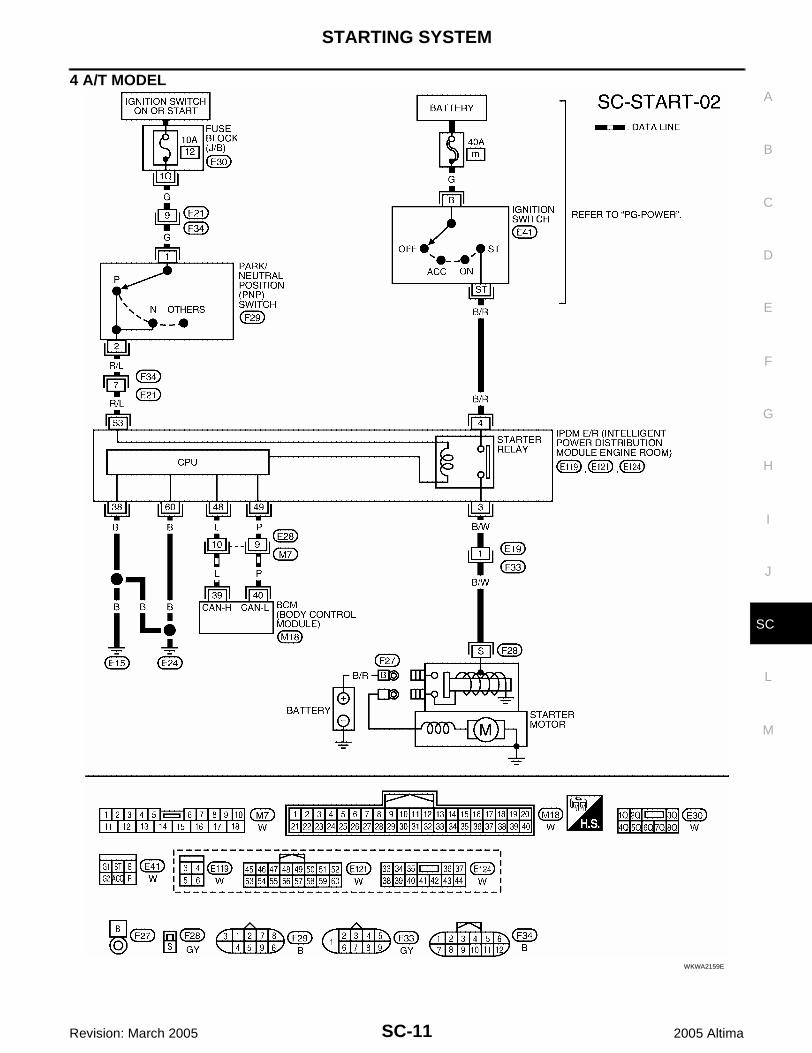
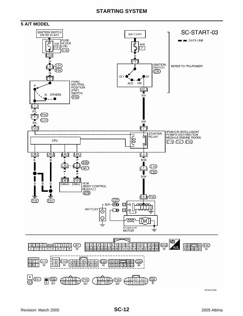
A/T MODELSPower is supplied at all times:● through 40A fusible link (letter m , located in the fuse and fusible link box)● to ignition switch terminal B.With the ignition switch in the START position, power is supplied:● from ignition switch terminal ST● to IPDM E/R terminal 4.With the ignition switch in the ON or START position, power is supplied:● through 10A fuse [No. 12, located in the fuse block (J/B)]● to park/neutral (PNP) switch terminal 1 (with 4 A/T) or terminal 5 (with 5 A/T).With the selector lever in P or N position, power is supplied:● through PNP switch terminal 2 (with 4 A/T) or terminal 1 (with 5 A/T)● to IPDM E/R terminal 53.Provided the IPDM E/R receives a starter relay request ON signal from the BCM over the CAN lines, the IPDME/R grounds the starter relay and power is supplied:● from terminal 3 of the IPDM E/R ● to terminal S of the starter motor windings.The starter motor plunger closes and provides a closed circuit between the battery and the starter motor. Thestarter motor is grounded to the cylinder block. With power and ground supplied, the starter motor operates.In the event that the CAN communication line fails between the IPDM E/R and the BCM, the IPDM E/R willdefault to a starter relay request ON signal as long as the ignition switch remains in the START or ON position.
CAN Communication System Description EKS008L1
Refer to LAN-21, "CAN COMMUNICATION" .

SC-10
STARTING SYSTEM
Revision: March 2005 2005 Altima
Wiring Diagram — START — EKS008L2
M/T MODELS
WKWA2905E
STARTING SYSTEM
SC-11
C
D
E
F
G
H
I
J
L
M
A
B
SC
Revision: March 2005 2005 Altima
4 A/T MODEL
WKWA2159E
SC-12
STARTING SYSTEM
Revision: March 2005 2005 Altima
5 A/T MODEL
WKWA2160E

STARTING SYSTEM
SC-13
C
D
E
F
G
H
I
J
L
M
A
B
SC
Revision: March 2005 2005 Altima
Trouble Diagnoses with Battery/Starting/Charging System Tester EKS008L3
NOTE:To ensure a complete and thorough diagnosis, the battery, starter and generator test segments must be doneas a set from start to finish.1. Turn off all loads on the vehicle electrical system.2. Perform battery test with Battery/Starting/Charging system
tester. Refer to SC-6, "Trouble Diagnoses with Battery/Starting/Charging System Tester" .
3. Press “ENTER” to begin the starting system test.
4. Start the engine.
5. Diagnosis result is displayed on the tester. Refer to SC-13,"DIAGNOSTIC RESULT ITEM CHART" .NOTE:● If the starter performs normally but the engine does not start,
perform engine diagnosis.● For intermittent “NO CRANK” or “NO STARTER OPERA-
TION” incidents, refer to SC-16, "DIAGNOSTIC PROCE-DURE 2" .
DIAGNOSTIC RESULT ITEM CHART
SEL408X
SEL409X
SEL410X
Diagnostic item Service procedure
CRANKING VOLTAGE NORMAL Go to “WORK FLOW”, SC-14, "WORK FLOW" .
CRANKING VOLTAGE LOW Go to “WORK FLOW”, SC-14, "WORK FLOW" .
CHARGE BATTERYPerform the slow battery charging procedure. (Initial rate of charge is 10A for 12 hours.) Per-form battery test again with Battery/Starting/Charging system tester. Refer to SC-6, "Trouble Diagnoses with Battery/Starting/Charging System Tester" .
REPLACE BATTERY
Before replacing battery, clean the battery cable clamps and battery posts. Perform battery test again with Battery/Starting/Charging system tester. Refer to SC-6, "Trouble Diagnoses with Battery/Starting/Charging System Tester" . If second test result is “REPLACE BAT-TERY”, then do so. Perform battery test again to confirm repair.
SC-14
STARTING SYSTEM
Revision: March 2005 2005 Altima
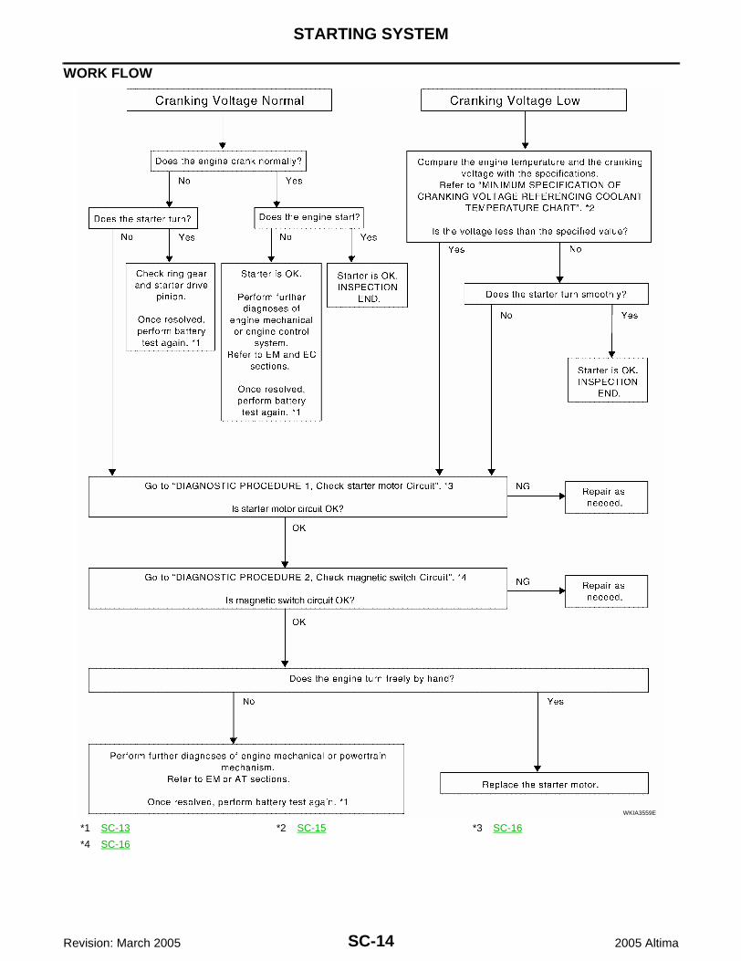
WORK FLOW
*1 SC-13 *2 SC-15 *3 SC-16
*4 SC-16
WKIA3559E

STARTING SYSTEM
SC-15
C
D
E
F
G
H
I
J
L
M
A
B
SC
Revision: March 2005 2005 Altima
DIAGNOSTIC PROCEDURE 1Check Starter Motor Circuit
1. CHECK POWER SUPPLY TO STARTER MOTOR
1. Remove the fuel pump fuse.2. Crank or start the engine (where possible) until the fuel pressure is released.3. Turn the ignition switch OFF.4. Check that the starter motor connector F27 terminal B (B/R) connection is clean and tight.5. Check voltage between starter motor connector F27 terminal B
(B/R) and ground using a digital circuit tester.
OK or NGOK >> GO TO 2.NG >> Check harness between the battery and the starter
motor for open circuit.
2. CHECK VOLTAGE DROP ON STARTER MOTOR CIRCUIT
1. Turn the ignition switch to START.2. Check voltage between starter motor connector F27 terminal B
(B/R) and battery positive terminal using a digital circuit tester.
OK or NGOK >> GO TO 3.NG >> Check harness between the battery and the starter
motor for poor continuity.
3. CHECK VOLTAGE DROP ON STARTER MOTOR GROUND CIRCUIT
1. Turn the ignition switch to START.2. Check voltage between starter motor case and battery negative
terminal using a digital circuit tester.
OK or NGOK >> Starter motor ground circuit is OK. Further inspection is
necessary. Refer to SC-14, "WORK FLOW" .NG >> Check for poor continuity between the starter motor
case and battery negative terminal.
Battery voltage should exist.
WKIA0137E
Ignition switch in START.
: Less than 0.5V
WKIA0138E
Ignition switch in START.
: Less than 0.2V
WKIA0139E

SC-16
STARTING SYSTEM
Revision: March 2005 2005 Altima
DIAGNOSTIC PROCEDURE 2Check Magnetic Switch Circuit
1. CHECK POWER SUPPLY FOR MAGNETIC SWITCH
1. Remove the fuel pump fuse.2. Crank or start the engine (where possible) until the fuel pressure is released.3. Turn the ignition switch OFF.4. Disconnect starter motor connector F28.5. Check voltage between starter motor connector F28 terminal S
(B/W) and ground using a digital circuit tester.
OK or NGOK >> GO TO 2.NG >> Check the following.
● 40A fusible link (letter m , located in fuse and fusiblelink box)
● Starter relay [within the intelligent power distributionmodule engine room (IPDM E/R)]
● Harness for open or short
2. CHECK VOLTAGE DROP ON MAGNETIC SWITCH CIRCUIT
1. Connect starter motor connector F28.2. Check voltage between starter motor connector F28 terminal S
(B/W) and battery positive terminal using a digital tester.
OK or NGOK >> Magnetic switch circuit is OK. Further inspection is nec-
essary. Refer to SC-14, "WORK FLOW" .NG >> Check harness between the battery and the magnetic
switch for poor continuity.
Ignition switch in START.
: Battery voltage
WKIA1549E
Ignition switch in START.
: Less than 1V
WKIA1550E

STARTING SYSTEM
SC-17
C
D
E
F
G
H
I
J
L
M
A
B
SC
Revision: March 2005 2005 Altima
MINIMUM SPECIFICATION OF CRANKING VOLTAGE REFERENCING COOLANT TEMPERA-TURE
Removal and Installation EKS008L4
M/T MODELSREMOVAL1. Disconnect the negative battery terminal.2. Remove the air cleaner cover and the air cleaner to intake man-
ifold collector duct.3. Remove the harness protector from the starter motor engine
room harness.4. Disconnect the starter motor harness connectors.5. Remove the two starter motor bolts, using power tools.6. Remove the starter motor.
INSTALLATIONInstallation is in the reverse order of removal.
Removal and Installation EKS00C2R
4-SPEED A/T MODELSREMOVAL1. Disconnect the negative battery terminal.2. Remove the air cleaner case (upper) and the air cleaner to electric throttle control actuator tube.3. Remove the harness protector from the starter engine room harness.4. Disconnect the starter harness connectors.
Engine coolant temperatureVoltage V
QR25DE VQ35DE
−30°C to −20°C (−22°F to −4°F) 8.7 8.4
−19°C to −10°C (−2°F to 14°F) 9.2 8.9
−9°C to 0°C (16°F to 32°F) 9.6 9.3
More than 1°C (More than 34°F) 10.0 9.7
WKWA0065E
WKIA0394E

SC-18
STARTING SYSTEM
Revision: March 2005 2005 Altima
5. Remove the two starter bolts, using power tools.6. Remove the starter.
INSTALLATIONInstallation is in the reverse order of removal.
Removal and Installation EKS00C2Q
5-SPEED A/T MODELSREMOVAL1. Disconnect the negative battery terminal.2. Remove the starter insulator.
3. Remove the harness bracket and harness protector from the starter engine room harness.4. Disconnect the starter harness connectors.
WKIA2058E
WKIA0400E

STARTING SYSTEM
SC-19
C
D
E
F
G
H
I
J
L
M
A
B
SC
Revision: March 2005 2005 Altima
5. Remove the two starter bolts, using power tools.6. Remove the starter.
INSTALLATIONInstallation is in the reverse order of removal.
WKIA0397E

SC-20
STARTING SYSTEM
Revision: March 2005 2005 Altima
Pinion/Clutch Check EKS008L5
1. Inspect pinion assembly teeth.● Replace pinion assembly if teeth are worn or damaged. (Also check condition of ring gear teeth.)
2. Inspect planetary gears/planetary gear teeth.● Replace planetary gears/planet gears if teeth are worn or damaged. (Also check condition of pinion
shaft/drive shaft gear teeth.)3. Check to see if pinion assembly locks in one direction and rotates smoothly in the opposite direction.
● If it locks or rotates in both directions, or if unusual resistance is evident, replace.

CHARGING SYSTEM
SC-21
C
D
E
F
G
H
I
J
L
M
A
B
SC
Revision: March 2005 2005 Altima
CHARGING SYSTEM PFP:23100
System Description EKS008L6
The generator provides DC voltage to operate the vehicle's electrical system and to keep the battery charged.The voltage output is controlled by the IC regulator.Power is supplied at all times to generator terminal B through:● 120A fusible link (letter a , located in the fusible link box).Power is supplied at all times to generator terminal S through:● 10A fuse (No. 26, located in the fuse and fusible link box).Terminal B supplies power to charge the battery and operate the vehicle's electrical system. Output voltage iscontrolled by the IC regulator at terminal S detecting the input voltage. The charging circuit is protected by the120A fusible link.The generator is grounded to the engine block.With the ignition switch in the ON or START position, power is supplied:● through 10A fuse [No. 14, located in the fuse block (J/B)]● to combination meter terminal 22 for the charge warning lamp.Ground is supplied to terminal 14 of the combination meter through terminal L of the generator. With powerand ground supplied, the charge warning lamp will illuminate. When the generator is providing sufficient volt-age with the engine running, the ground is opened and the charge warning lamp will go off.If the charge warning lamp illuminates with the engine running, a fault is indicated.

SC-22
CHARGING SYSTEM
Revision: March 2005 2005 Altima
Wiring Diagram — CHARGE — EKS008L7
WKWA1355E

CHARGING SYSTEM
SC-23
C
D
E
F
G
H
I
J
L
M
A
B
SC
Revision: March 2005 2005 Altima
Trouble Diagnoses with Battery/Starting/Charging System Tester EKS008L8
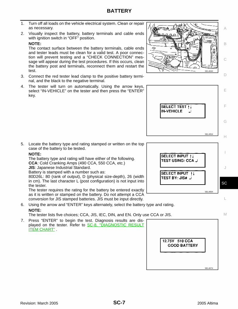
NOTE:To ensure a complete and thorough diagnosis, the battery, starter and generator test segments must be doneas a set from start to finish.1. Turn off all loads on the vehicle electrical system.2. Perform battery and starting system test with Battery/Starting/
Charging system tester.3. Press “ENTER” to begin the charging system test.4. Start engine.
5. Press “ENTER” until “LOADS OFF REV ENGINE 5 SEC” is dis-played.
6. Raise and hold the engine speed at 1,500 to 2,000 rpm for about5 seconds, then return the engine to idle.Once the increase in engine rpm is detected, press “ENTER” tocontinue.NOTE:● If after 30 seconds an increase in engine idle speed is not
detected, “RPM NOT DETECTED” will display.● Some engines may have a higher idle initially after starting,
particularly when the engine is cold. The tester may detectthis without any other action being taken. If this occurs, con-tinue on with the testing process. The final results will not be affected.
7. The tester now checks the engine at idle and performs theDIODE/RIPPLE check.
8. When complete, the tester will prompt you to turn on the follow-ing electrical loads.● Heater fan set to highest speed. Do not run the A/C or wind-
shield defroster.● Headlamp high beam● Rear window defoggerNOTE:Do not run the windshield wipers or any other cyclical loads.
9. Press “ENTER” to continue.
SEL417X
SEL418X
SEL419X
SEL420X
SC-24
CHARGING SYSTEM
Revision: March 2005 2005 Altima
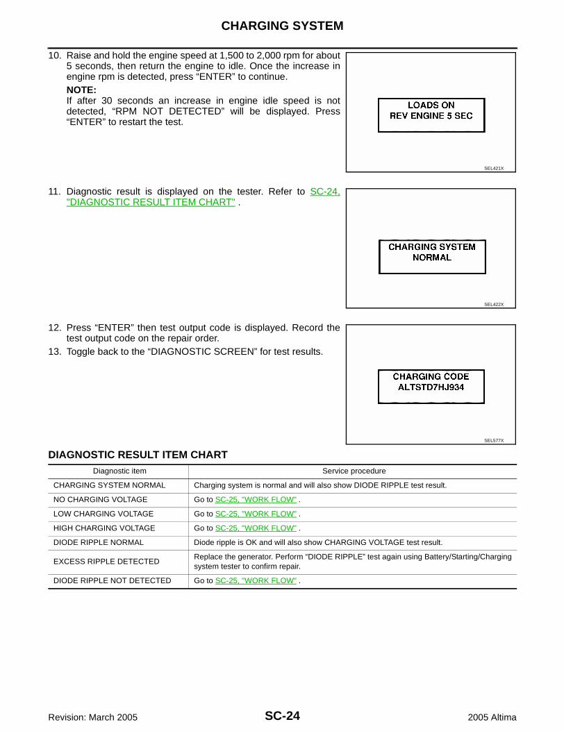
10. Raise and hold the engine speed at 1,500 to 2,000 rpm for about5 seconds, then return the engine to idle. Once the increase inengine rpm is detected, press “ENTER” to continue.NOTE:If after 30 seconds an increase in engine idle speed is notdetected, “RPM NOT DETECTED” will be displayed. Press“ENTER” to restart the test.
11. Diagnostic result is displayed on the tester. Refer to SC-24,"DIAGNOSTIC RESULT ITEM CHART" .
12. Press “ENTER” then test output code is displayed. Record thetest output code on the repair order.
13. Toggle back to the “DIAGNOSTIC SCREEN” for test results.
DIAGNOSTIC RESULT ITEM CHART
SEL421X
SEL422X
SEL577X
Diagnostic item Service procedure
CHARGING SYSTEM NORMAL Charging system is normal and will also show DIODE RIPPLE test result.
NO CHARGING VOLTAGE Go to SC-25, "WORK FLOW" .
LOW CHARGING VOLTAGE Go to SC-25, "WORK FLOW" .
HIGH CHARGING VOLTAGE Go to SC-25, "WORK FLOW" .
DIODE RIPPLE NORMAL Diode ripple is OK and will also show CHARGING VOLTAGE test result.
EXCESS RIPPLE DETECTEDReplace the generator. Perform “DIODE RIPPLE” test again using Battery/Starting/Charging system tester to confirm repair.
DIODE RIPPLE NOT DETECTED Go to SC-25, "WORK FLOW" .

CHARGING SYSTEM
SC-25
C
D
E
F
G
H
I
J
L
M
A
B
SC
Revision: March 2005 2005 Altima
WORK FLOW
WKIA4022E

SC-26
CHARGING SYSTEM
Revision: March 2005 2005 Altima
DIAGNOSTIC PROCEDURE 1Check Charge Warning Lamp Circuit
1. CHECK CHARGE WARNING LAMP CIRCUIT CONNECTION
Check to see if terminal "L" is clean and tight.OK or NGOK >> GO TO 2.NG >> Repair terminal "L" connection. Confirm repair by performing complete Battery/Starting/Charging
system test.
2. CHECK CHARGE WARNING LAMP CIRCUIT
1. Disconnect F1 connector from generator.2. Apply ground to connector F1 terminal L (BR/Y) with the ignition
switch in the ON position.
OK or NGOK >> Replace the generator. Confirm repair by performing
complete Battery/Starting/Charging system test.NG >> Check the following.
● 10A fuse [No. 14, located in fuse block (J/B)]● CHARGE lamp● Harness for open or short between combination
meter and fuse● Harness for open or short between combination meter and generator
CHARGE lamp should light up.
WKIA0142E
CHARGING SYSTEM
SC-27
C
D
E
F
G
H
I
J
L
M
A
B
SC
Revision: March 2005 2005 Altima
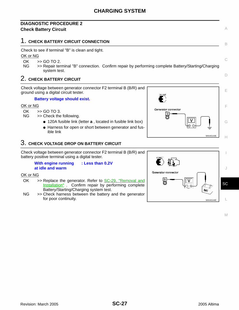
DIAGNOSTIC PROCEDURE 2Check Battery Circuit
1. CHECK BATTERY CIRCUIT CONNECTION
Check to see if terminal "B" is clean and tight.OK or NGOK >> GO TO 2.NG >> Repair terminal "B" connection. Confirm repair by performing complete Battery/Starting/Charging
system test.
2. CHECK BATTERY CIRCUIT
Check voltage between generator connector F2 terminal B (B/R) andground using a digital circuit tester.
OK or NGOK >> GO TO 3.NG >> Check the following.
● 120A fusible link (letter a , located in fusible link box)● Harness for open or short between generator and fus-
ible link
3. CHECK VOLTAGE DROP ON BATTERY CIRCUIT
Check voltage between generator connector F2 terminal B (B/R) andbattery positive terminal using a digital tester.
OK or NGOK >> Replace the generator. Refer to SC-29, "Removal and
Installation" . Confirm repair by performing completeBattery/Starting/Charging system test.
NG >> Check harness between the battery and the generatorfor poor continuity.
Battery voltage should exist.
WKIA0143E
With engine running at idle and warm
: Less than 0.2V
WKIA0144E

SC-28
CHARGING SYSTEM
Revision: March 2005 2005 Altima
DIAGNOSTIC PROCEDURE 3Check Voltage Regulator Circuit
1. CHECK VOLTAGE REGULATOR CIRCUIT CONNECTION
Check to see if terminal "S" is clean and tight.OK or NGOK >> GO TO 2.NG >> Repair terminal "S" connection. Confirm repair by performing complete Battery/Starting/Charging
system test.
2. CHECK VOLTAGE REGULATOR CIRCUIT
Check voltage between generator connector F1 terminal S (Y/B) andground using a digital circuit tester.
OK or NGOK >> GO TO 3.NG >> Check the following.
● 10A fuse (No. 26, located in fuse and fusible link box)● Harness for open or short between generator and
fuse
3. CHECK VOLTAGE DROP ON VOLTAGE REGULATOR CIRCUIT
Check voltage between generator connector F1 terminal S (Y/B) andbattery positive terminal using a digital tester.
OK or NGOK >> Replace the generator. Refer to SC-29, "Removal and
Installation" . Confirm repair by performing completeBattery/Starting/Charging system test.
NG >> Check harness between the battery and the generatorfor poor continuity.
Battery voltage should exist.
WKIA0145E
With engine running at idle and warm.
: Less than 0.2V
WKIA0146E
CHARGING SYSTEM
SC-29
C
D
E
F
G
H
I
J
L
M
A
B
SC
Revision: March 2005 2005 Altima
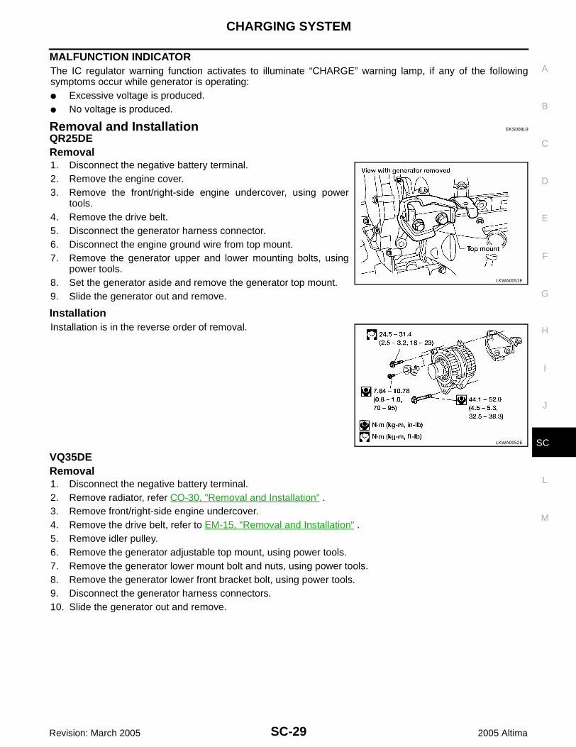
MALFUNCTION INDICATORThe IC regulator warning function activates to illuminate “CHARGE” warning lamp, if any of the followingsymptoms occur while generator is operating:● Excessive voltage is produced.● No voltage is produced.
Removal and Installation EKS008L9
QR25DERemoval1. Disconnect the negative battery terminal.2. Remove the engine cover.3. Remove the front/right-side engine undercover, using power
tools.4. Remove the drive belt.5. Disconnect the generator harness connector.6. Disconnect the engine ground wire from top mount.7. Remove the generator upper and lower mounting bolts, using
power tools.8. Set the generator aside and remove the generator top mount.9. Slide the generator out and remove.
InstallationInstallation is in the reverse order of removal.
VQ35DERemoval1. Disconnect the negative battery terminal.2. Remove radiator, refer CO-30, "Removal and Installation" .3. Remove front/right-side engine undercover.4. Remove the drive belt, refer to EM-15, "Removal and Installation" .5. Remove idler pulley. 6. Remove the generator adjustable top mount, using power tools.7. Remove the generator lower mount bolt and nuts, using power tools.8. Remove the generator lower front bracket bolt, using power tools.9. Disconnect the generator harness connectors.10. Slide the generator out and remove.
LKWA0051E
LKWA0052E
SC-30
CHARGING SYSTEM
Revision: March 2005 2005 Altima
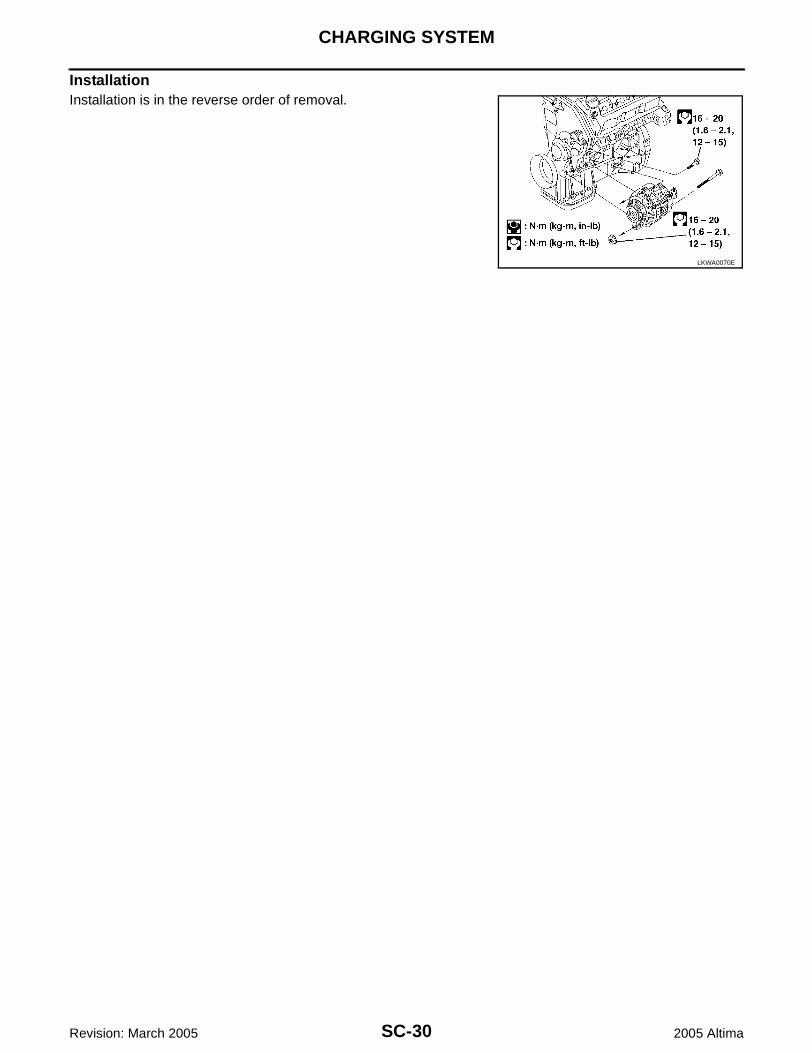
InstallationInstallation is in the reverse order of removal.
LKWA0070E
SERVICE DATA AND SPECIFICATIONS (SDS)
SC-31
C
D
E
F
G
H
I
J
L
M
A
B
SC
Revision: March 2005 2005 Altima
SERVICE DATA AND SPECIFICATIONS (SDS) PFP:00030
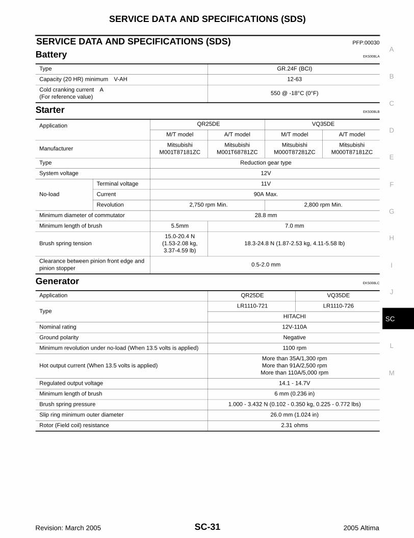
Battery EKS008LA
Starter EKS008LB
Generator EKS008LC
Type GR.24F (BCI)
Capacity (20 HR) minimum V-AH 12-63
Cold cranking current A(For reference value)
550 @ -18°C (0°F)
Application QR25DE VQ35DE
M/T model A/T model M/T model A/T model
ManufacturerMitsubishi
M001T87181ZCMitsubishi
M001T68781ZCMitsubishi
M000T87281ZCMitsubishi
M000T87181ZC
Type Reduction gear type
System voltage 12V
No-load
Terminal voltage 11V
Current 90A Max.
Revolution 2,750 rpm Min. 2,800 rpm Min.
Minimum diameter of commutator 28.8 mm
Minimum length of brush 5.5mm 7.0 mm
Brush spring tension15.0-20.4 N
(1.53-2.08 kg,3.37-4.59 lb)
18.3-24.8 N (1.87-2.53 kg, 4.11-5.58 lb)
Clearance between pinion front edge and pinion stopper
0.5-2.0 mm
Application QR25DE VQ35DE
TypeLR1110-721 LR1110-726
HITACHI
Nominal rating 12V-110A
Ground polarity Negative
Minimum revolution under no-load (When 13.5 volts is applied) 1100 rpm
Hot output current (When 13.5 volts is applied)More than 35A/1,300 rpmMore than 91A/2,500 rpmMore than 110A/5,000 rpm
Regulated output voltage 14.1 - 14.7V
Minimum length of brush 6 mm (0.236 in)
Brush spring pressure 1.000 - 3.432 N (0.102 - 0.350 kg, 0.225 - 0.772 lbs)
Slip ring minimum outer diameter 26.0 mm (1.024 in)
Rotor (Field coil) resistance 2.31 ohms

SC-32
SERVICE DATA AND SPECIFICATIONS (SDS)
Revision: March 2005 2005 Altima
Copyright © 2022 FDOKUMEN