Design of an epicycloidal geartrain for a four-wheel drive ...
223
POLITECNICO DI TORINO Master degree course in Automotive engineering Master Degree Thesis Design of an epicycloidal geartrain for a four-wheel drive Formula Student electric vehicle Supervisors prof. Andrea Tonoli Candidates Marco Cova S 253438 Academic year 2019-2020
-
Upload
khangminh22 -
Category
Documents
-
view
1 -
download
0
Transcript of Design of an epicycloidal geartrain for a four-wheel drive ...

POLITECNICO DI TORINOMaster degree course in Automotive engineering
Master Degree Thesis
Design of an epicycloidalgeartrain for a four-wheel drive
Formula Student electricvehicle
Supervisorsprof. Andrea Tonoli
Candidates
Marco CovaS 253438
Academic year 2019-2020

This work is subject to the Creative Commons Licence

Abstract
Formula Student or Formula SAE is a competition between student teamsin charge of designing, building and testing a new formula-style race car pereach season. Those vehicles are divided into three classes: Combustion, Elec-tric and Driverless. The competition consists in both a static part where thedesign, the cost-performance relationship and the marketing aspects of theproject are evaluated by the judges and a dynamic part where the vehiclemust race in four different type of events. Each dynamic event highlights dif-ferent aspects of the car performance, from standstill acceleration to lateralgrip, reliability and energy efficiency.
In 2005 Politecnico di Torino’s Formula Student team called Squadra CorsePoliTo was founded and since then fifteen cars have been built. Seven of themare powered by an Internal Combustion Engine, one is a Hybrid Electric Ve-hicle, while the last six cars built are Battery Electric Vehicles.
SC18integrale is the vehicle presented by Squadra Corse PoliTo for the2018/2019 racing season. It is a four-wheel drive Battery Electric Vehiclewith four independent in-wheel motors. The motors need a devoted gearboxin order to match the vehicle’s traction requirement. Due to the in-wheelposition both the weight and the volume of the gearbox are critical param-eters. The weight impacts on the unsprung masses, while a small volume isbeneficial for suspension hardpoints package.
In this thesis the project of the SC18integrale epicycloidal transmission ispresented in all its aspects, from the concept design until the track validation.The first phase of the design after the target has been set is the development

of the transmission model and of the gear life calculation, carried by KISS-soft and KISSsys software tools, then the integration of the gearbox with thewheel assembly is studied. Finally the mechanical design of each componentand of the assembly is detailed.
Catia V5 is the software used for the development of CAD models whileAltair Hyperworks the software used to carry the structural FEA. The ex-perimental validation is done on track during the pre-season tests, the racingevents and the post-season test phase.
2

Acknowledgements
Alla fine di questo percorso che, malgrado la grande soddisfazione, per qualchemotivo mi è sembrato più lungo di quanto effettivamente sia stato, ci tengo ascrivere qualche parola di ringraziamento rivolta a quelle persone che hannoreso il raggiungimento di questo traguardo possibile e più semplice.
Prima di tutto e di tutti vorrei ringraziare i miei genitori, Paolo e Mar-iangela, che da sempre mi supportano in ogni modo possibile, senza il lorocostante aiuto ed i loro sacrifici tutto ciò sarebbe stato certamente irrealiz-zabile. Un ringraziamento particolare va a mia sorella, Francesca, una dellepersone più importanti della mia vita, nonché una delle prime che mi abbiasopportato e che mi sia stata vicina; malgrado l’attualmente maggiore dis-tanza geografica continua a fare entrambe le cose.
Vorrei anche ringraziare le mie nonne, Angela e Lena, sempre presentinella mia vita e probabilmente il massimo esempio di gentilezza e disponi-biltà che una persona possa pensare di raggiungere. Sono sicuro che questotraguardo le renda felici e fiere di me.
Desidero ringraziare i miei zii, Stefano e Antonella, e con loro i miei cugini,Pietro, Marta e Giacomo. Mai distanti, ho sempre potuto contare su di loroin questi anni e sono certo di poter continuare a farlo.
3

Doveroso ringraziare il Team Squadra Corse, palestra di vita e di Motor-sport, per me grande fattore di crescita personale e professionale. In parti-colare il Professor Andrea Tonoli che da oramai quindici anni crede in noi efa sì che sempre più studenti conoscano questa realtà, Stefano e Marco con iquali ho condiviso moltissimo tempo, prima in Squadra e poi come colleghi,Edoardo che ha lavorato con me su questo progetto, diventandone parte in-tegrante e contribuendo in modo sostanziale alla sua riuscita, e Giovanni cheun po’ di anni fa mi mise una “pulce nell’orecchio”. Grazie anche a tutte lealtre persone che con me non si sono mai risparmiate e hanno investito tuttele loro energie nel progetto, colleghi, ma soprattutto amici.
Lascio per ultimo un ringraziamento per me molto importante, a Giulia,che da più di due anni mi sostiene, mi sopporta, mi incoraggia e rende miglioreogni istante trascorso. Insieme siamo cresciuti in molti aspetti delle nostrevite e continueremo a farlo, non potrei immaginare una persona migliore almio fianco.
4

Contents
List of Figures 10
List of Tables 17
I First part 19
1 Introduction 211.1 Formula Student . . . . . . . . . . . . . . . . . . . . . . . . . 211.2 Squadra Corse PoliTo . . . . . . . . . . . . . . . . . . . . . . . 231.3 SC18integrale project . . . . . . . . . . . . . . . . . . . . . . . 23
2 Gear trains for Formula Student Electric cars 252.1 Solutions designed by Squadra Corse . . . . . . . . . . . . . . 25
2.1.1 Before planetary gear trains . . . . . . . . . . . . . . . 252.1.2 SCXV and SCXV Evo . . . . . . . . . . . . . . . . . . 262.1.3 SCdiciassette . . . . . . . . . . . . . . . . . . . . . . . 27
2.2 Benchmark . . . . . . . . . . . . . . . . . . . . . . . . . . . . 282.2.1 University Racing Eindhoven . . . . . . . . . . . . . . 282.2.2 AMZ Racing Team . . . . . . . . . . . . . . . . . . . . 292.2.3 DHBW Engineering Stuttgart e.V. . . . . . . . . . . . 302.2.4 KA-RaceIng . . . . . . . . . . . . . . . . . . . . . . . . 31
5

3 Project Set-Up 333.1 SC18integrale wheel assembly . . . . . . . . . . . . . . . . . . 333.2 Target setting . . . . . . . . . . . . . . . . . . . . . . . . . . . 343.3 Gear train integration with the vehicle . . . . . . . . . . . . . 35
3.3.1 Motors . . . . . . . . . . . . . . . . . . . . . . . . . . . 353.3.2 Wheel integration . . . . . . . . . . . . . . . . . . . . . 36
3.4 Transmission ratio choice . . . . . . . . . . . . . . . . . . . . . 373.5 Layout choice . . . . . . . . . . . . . . . . . . . . . . . . . . . 383.6 Meshing rule . . . . . . . . . . . . . . . . . . . . . . . . . . . . 403.7 Load spectrum and required service life . . . . . . . . . . . . . 413.8 Design flow . . . . . . . . . . . . . . . . . . . . . . . . . . . . 44
4 Transmission model 474.1 Introduction to KISSsys . . . . . . . . . . . . . . . . . . . . . 474.2 SC18integrale transmission model . . . . . . . . . . . . . . . . 48
4.2.1 Elements involved . . . . . . . . . . . . . . . . . . . . . 484.2.2 Model build . . . . . . . . . . . . . . . . . . . . . . . . 49
4.3 Calculation modules . . . . . . . . . . . . . . . . . . . . . . . 544.3.1 Coaxial shafts calculation . . . . . . . . . . . . . . . . 544.3.2 Gear pair calculation module . . . . . . . . . . . . . . 56
5 Gear life calculation 575.1 Introduction to KISSsoft . . . . . . . . . . . . . . . . . . . . . 57
5.1.1 Basic data . . . . . . . . . . . . . . . . . . . . . . . . . 585.1.2 Reference profile . . . . . . . . . . . . . . . . . . . . . 585.1.3 Tolerances . . . . . . . . . . . . . . . . . . . . . . . . . 595.1.4 Rating . . . . . . . . . . . . . . . . . . . . . . . . . . . 595.1.5 Factors . . . . . . . . . . . . . . . . . . . . . . . . . . . 595.1.6 Output plots . . . . . . . . . . . . . . . . . . . . . . . 60
5.2 ISO 6336:2006 Standard . . . . . . . . . . . . . . . . . . . . . 60
6

5.2.1 Pitting load capacity . . . . . . . . . . . . . . . . . . . 625.2.2 Fracture load capacity . . . . . . . . . . . . . . . . . . 63
5.3 Material choice . . . . . . . . . . . . . . . . . . . . . . . . . . 635.4 Calculation set-up . . . . . . . . . . . . . . . . . . . . . . . . . 695.5 Results . . . . . . . . . . . . . . . . . . . . . . . . . . . . . . . 74
5.5.1 Final geometry definition . . . . . . . . . . . . . . . . . 745.5.2 Life calculation results . . . . . . . . . . . . . . . . . . 78
6 Wheel bearings 836.1 Layout and bearing choice . . . . . . . . . . . . . . . . . . . . 836.2 Bearings life calculation . . . . . . . . . . . . . . . . . . . . . 86
6.2.1 Load spectrum . . . . . . . . . . . . . . . . . . . . . . 866.2.2 Life calculation results . . . . . . . . . . . . . . . . . . 88
6.3 Axial preload . . . . . . . . . . . . . . . . . . . . . . . . . . . 90
7 Mechanical design of gear train components 957.1 Sun gear . . . . . . . . . . . . . . . . . . . . . . . . . . . . . . 95
7.1.1 Component engineering . . . . . . . . . . . . . . . . . . 957.1.2 Geometric oscillations of the motor output shaft . . . . 997.1.3 Analysis of the motor output shaft under load . . . . . 1017.1.4 Manufacturing . . . . . . . . . . . . . . . . . . . . . . 103
7.2 Ring gear . . . . . . . . . . . . . . . . . . . . . . . . . . . . . 1057.2.1 Component engineering . . . . . . . . . . . . . . . . . . 1057.2.2 Structural analysis . . . . . . . . . . . . . . . . . . . . 1087.2.3 Manufacturing . . . . . . . . . . . . . . . . . . . . . . 109
7.3 Planetary gears assembly . . . . . . . . . . . . . . . . . . . . . 1107.3.1 Components engineering . . . . . . . . . . . . . . . . . 1107.3.2 Torque transmission . . . . . . . . . . . . . . . . . . . 1147.3.3 Pin shaft structural analysis . . . . . . . . . . . . . . . 1167.3.4 Planet gear structural analysis . . . . . . . . . . . . . . 117
7

7.3.5 Assembly tolerances . . . . . . . . . . . . . . . . . . . 1207.3.6 Manufacturing . . . . . . . . . . . . . . . . . . . . . . 123
8 Planetary carrier mechanical design 1258.1 Layout . . . . . . . . . . . . . . . . . . . . . . . . . . . . . . . 1258.2 Wheel locknut . . . . . . . . . . . . . . . . . . . . . . . . . . . 1268.3 Materials choice . . . . . . . . . . . . . . . . . . . . . . . . . . 1278.4 FEM analysis and optimization . . . . . . . . . . . . . . . . . 129
8.4.1 Loads . . . . . . . . . . . . . . . . . . . . . . . . . . . 1298.4.2 Optimization . . . . . . . . . . . . . . . . . . . . . . . 1318.4.3 Final FEM model . . . . . . . . . . . . . . . . . . . . . 135
8.5 Manufacturing and tolerances . . . . . . . . . . . . . . . . . . 145
9 Lubrication 1479.1 Lubricant choice . . . . . . . . . . . . . . . . . . . . . . . . . . 1479.2 Seals . . . . . . . . . . . . . . . . . . . . . . . . . . . . . . . . 149
9.2.1 Radial shaft seal . . . . . . . . . . . . . . . . . . . . . 1509.2.2 O-Ring . . . . . . . . . . . . . . . . . . . . . . . . . . . 152
9.3 Lubricant level . . . . . . . . . . . . . . . . . . . . . . . . . . 153
10 Efficiency analysis 15510.1 Power losses . . . . . . . . . . . . . . . . . . . . . . . . . . . . 15510.2 Gearbox efficiency model . . . . . . . . . . . . . . . . . . . . . 15710.3 Results . . . . . . . . . . . . . . . . . . . . . . . . . . . . . . . 159
11 Assembly 16311.1 Upright group assembly . . . . . . . . . . . . . . . . . . . . . 16311.2 Motor group assembly . . . . . . . . . . . . . . . . . . . . . . 169
12 Final transmission assembly 17112.1 Transmission assembly . . . . . . . . . . . . . . . . . . . . . . 171
8

12.2 Transmission integration . . . . . . . . . . . . . . . . . . . . . 173
II Second part 175
13 Results obtained 17713.1 Weight reduction . . . . . . . . . . . . . . . . . . . . . . . . . 17713.2 Volume reduction . . . . . . . . . . . . . . . . . . . . . . . . . 17913.3 Assembly process . . . . . . . . . . . . . . . . . . . . . . . . . 18013.4 Formula Student Spain failure . . . . . . . . . . . . . . . . . . 18313.5 Gearbox life . . . . . . . . . . . . . . . . . . . . . . . . . . . . 18413.6 Motor working points . . . . . . . . . . . . . . . . . . . . . . . 185
14 Conclusions and future perspectives 18914.1 Conclusions . . . . . . . . . . . . . . . . . . . . . . . . . . . . 18914.2 Future perspectives . . . . . . . . . . . . . . . . . . . . . . . . 190
APPENDICES 190
A AMK motor datasheet 191
B Double stage epicycloidal gearboxes layouts 195
C Wheel locknut tightening torque computation 197
D Gear train technical drawings 201
E Planetary carrier assembly technical drawings 211
F Lubricant datasheet 217
Bibliography 219
9

List of Figures
1.1 SC18integrale . . . . . . . . . . . . . . . . . . . . . . . . . . . 242.1 SC12e with its gear train [19] . . . . . . . . . . . . . . . . . . 262.2 SCR with its geartrain [19] . . . . . . . . . . . . . . . . . . . . 262.3 SCXV with its gear train [19] . . . . . . . . . . . . . . . . . . 272.4 SCdiciassette with its gear train . . . . . . . . . . . . . . . . . 282.5 University Racing Eindhoven transmission . . . . . . . . . . . 292.6 University Racing Eindhoven transmission . . . . . . . . . . . 292.7 AMZ Racing Team transmission . . . . . . . . . . . . . . . . . 302.8 DHBW Engineering Stuttgart e.V. . . . . . . . . . . . . . . . 302.9 KA-RaceIng wheel assembly . . . . . . . . . . . . . . . . . . . 313.1 SC18integrale view . . . . . . . . . . . . . . . . . . . . . . . . 343.2 Characteristic curves of the AMK DD5-14-10-POW motor . . 363.3 Section view of the wheel assembly . . . . . . . . . . . . . . . 373.4 Dual stage planetary gearbox . . . . . . . . . . . . . . . . . . 393.5 Schematic of the SC18integrale transmission . . . . . . . . . . 393.6 Example of load spectrum, showing both the front and the
rear requested motor torque . . . . . . . . . . . . . . . . . . . 413.7 Front transmission load spectrum . . . . . . . . . . . . . . . . 433.8 Rear transmission load spectrum . . . . . . . . . . . . . . . . 433.9 Design flow . . . . . . . . . . . . . . . . . . . . . . . . . . . . 454.1 KISSsys model 3D view . . . . . . . . . . . . . . . . . . . . . 48
10

4.2 KISSsys model tree . . . . . . . . . . . . . . . . . . . . . . . . 504.3 Diagram of the transmission model . . . . . . . . . . . . . . . 544.4 Main line calculation module . . . . . . . . . . . . . . . . . . . 555.1 Reference profile . . . . . . . . . . . . . . . . . . . . . . . . . 595.2 Length of path of contact for a cylindrical gear . . . . . . . . . 605.3 Solutions for aluminum gears scattered as a function of the
normal module . . . . . . . . . . . . . . . . . . . . . . . . . . 655.4 Solutions for aluminum gears scattered as a function of the
centre distance . . . . . . . . . . . . . . . . . . . . . . . . . . 655.5 Properties comparison of case-hardening steels commonly used
for gears manufacturing . . . . . . . . . . . . . . . . . . . . . 665.6 Nominal time and temperature requirements for different case
depths . . . . . . . . . . . . . . . . . . . . . . . . . . . . . . . 675.7 Type of pinion shaft according to ISO 6336 Picture 13e . . . . 725.8 Tooth trace modification . . . . . . . . . . . . . . . . . . . . . 725.9 Alternate load factor determination . . . . . . . . . . . . . . . 735.10 Tip and root relief . . . . . . . . . . . . . . . . . . . . . . . . 755.11 First stage without (left) and with (right) tip relief modification 755.12 Fist stage meshing gears . . . . . . . . . . . . . . . . . . . . . 765.13 Second stage without (left) and with (right) end relief modifi-
cation . . . . . . . . . . . . . . . . . . . . . . . . . . . . . . . 775.14 Second stage meshing gears . . . . . . . . . . . . . . . . . . . 775.15 First stage specific sliding . . . . . . . . . . . . . . . . . . . . 785.16 Root stresses for the sun gear (left) and for the first planet
gear (right) under maximum torque . . . . . . . . . . . . . . . 795.17 First stage hardness curve recommendation . . . . . . . . . . . 795.18 Second stage specific sliding . . . . . . . . . . . . . . . . . . . 805.19 Root stresses for the second planet gear (left) and for the ring
gear (right) under maximum torque . . . . . . . . . . . . . . . 81
11

5.20 Second stage hardness curve recommendation . . . . . . . . . 816.1 SC18integrale wheel bearings layout . . . . . . . . . . . . . . . 846.2 Main dimensions for bearings of the type ACD,CD . . . . . . 846.3 Fx load spectrum where Fx >= 20 N . . . . . . . . . . . . . . 876.4 Fx load spectrum where Fy >= 20 N . . . . . . . . . . . . . . 876.5 Fz load spectrum . . . . . . . . . . . . . . . . . . . . . . . . . 886.6 Wheel bearings life as a function of axial preload . . . . . . . 896.7 Front peak contact loads on the external bearing (left) and on
the internal bearing (right) [14] . . . . . . . . . . . . . . . . . 906.8 Rear peak contact loads on the external bearing (left) and on
the internal bearing (right) [14] . . . . . . . . . . . . . . . . . 906.9 SC17 wheel assembly section . . . . . . . . . . . . . . . . . . . 916.10 SC18 wheel bearings preload . . . . . . . . . . . . . . . . . . . 927.1 SC17 sun shaft . . . . . . . . . . . . . . . . . . . . . . . . . . 957.2 Comparison between the sun gear assembly of the SCdicias-
sette (left) and the sun gear assembly of the SC18integrale(right) . . . . . . . . . . . . . . . . . . . . . . . . . . . . . . . 96
7.3 Motor mounting flange detail . . . . . . . . . . . . . . . . . . 977.4 Motor output spline . . . . . . . . . . . . . . . . . . . . . . . . 987.5 Motor output spline section view . . . . . . . . . . . . . . . . 987.6 Sun gear . . . . . . . . . . . . . . . . . . . . . . . . . . . . . . 997.7 Measurement set-up . . . . . . . . . . . . . . . . . . . . . . . 1007.8 Oscillation of the motor output spline top and root diameters
from their nominal value . . . . . . . . . . . . . . . . . . . . . 1007.9 Maximum oscillation of the motor output shaft non-splined
section . . . . . . . . . . . . . . . . . . . . . . . . . . . . . . . 1017.10 Radial forces due to meshing gear pairs acting on the sun gear 1027.11 Model of the motor output shaft in KISSsoft . . . . . . . . . . 1037.12 Motor shaft deflection . . . . . . . . . . . . . . . . . . . . . . 103
12

7.13 Carburized case pattern . . . . . . . . . . . . . . . . . . . . . 1047.14 SCdiciassette ring gear retention system . . . . . . . . . . . . 1057.15 Curved flank teeth solution . . . . . . . . . . . . . . . . . . . 1067.16 SC18 integrale ring gear retention system . . . . . . . . . . . . 1077.17 Ring gear . . . . . . . . . . . . . . . . . . . . . . . . . . . . . 1077.18 Ring gear FEM model . . . . . . . . . . . . . . . . . . . . . . 1087.19 Ring gear stress contour plot . . . . . . . . . . . . . . . . . . . 1097.20 Nominal times required for different nitride case depths . . . . 1107.21 Planetary gears assembly . . . . . . . . . . . . . . . . . . . . . 1117.22 Anti-rotation pin in the carrier (left) and spacer (right) . . . . 1137.23 Planet pin shaft . . . . . . . . . . . . . . . . . . . . . . . . . . 1137.24 Planet pin shaft rotational constrain . . . . . . . . . . . . . . 1147.25 Left display: tolerance field only takes allowances into account,
centre display: tolerance field takes into account temperatureand centrifugal force (without pressure), right display: tol-erance field takes into account temperature, centrifugal forceand pressure . . . . . . . . . . . . . . . . . . . . . . . . . . . . 115
7.26 Plot of the stresses of the press fit in the shaft and in the hub 1157.27 Planetary gear assembly model in KISSsoft . . . . . . . . . . . 1167.28 Planet pin shaft displacement (left) and stresses (right) . . . . 1177.29 Planetary gear FEM model . . . . . . . . . . . . . . . . . . . 1187.30 Planetary gear displacement . . . . . . . . . . . . . . . . . . . 1197.31 Planetary gear stress on a mid-plane section . . . . . . . . . . 1197.32 First stage meshing profiles with 33.6 centre distance . . . . . 1208.1 Planetary carrier . . . . . . . . . . . . . . . . . . . . . . . . . 1268.2 Maximum stress vs fatigue life for 7068-T6511 aluminum alloy 1288.3 Autocross g-g diagram . . . . . . . . . . . . . . . . . . . . . . 1308.4 Hub-carrier assembly before optimization . . . . . . . . . . . . 1318.5 Optimization design and non-design spaces . . . . . . . . . . . 132
13

8.6 Element density contour, rear view . . . . . . . . . . . . . . . 1338.7 Element density contour, isometric view . . . . . . . . . . . . 1338.8 Element density contour, section view . . . . . . . . . . . . . . 1338.9 Hub before (left) and after optimization (right) . . . . . . . . 1348.10 Planetary carrier before (left) and after optimization (right) . 1348.11 Components meshed in the model . . . . . . . . . . . . . . . . 1358.12 Particular showing the mesh size variation in the hub . . . . . 1368.13 View of the contact interfaces between the hub-carrier and the
bearings inner rings . . . . . . . . . . . . . . . . . . . . . . . . 1378.14 Pin shaft constraints . . . . . . . . . . . . . . . . . . . . . . . 1378.15 Wheel bearings constraints . . . . . . . . . . . . . . . . . . . . 1388.16 Loads application . . . . . . . . . . . . . . . . . . . . . . . . . 1398.17 Von Mises average stress contour plot - Hub . . . . . . . . . . 1408.18 Von Mises average stress contour plot - Hub . . . . . . . . . . 1408.19 Signed Von Mises average stress contour plot - Hub . . . . . . 1408.20 Signed Von Mises average stress contour plot - Hub . . . . . . 1418.21 Von Mises alternate stress contour plot - Hub . . . . . . . . . 1418.22 Signed Von Mises alternate stress contour plot - Hub . . . . . 1428.23 Haigh diagram example . . . . . . . . . . . . . . . . . . . . . . 1428.24 Haigh diagram of the most stressed section of the wheel hub . 1438.25 Von Mises stress contour plot - Planetary carrier . . . . . . . . 1448.26 Von Mises stress contour plot - Planetary carrier . . . . . . . . 1448.27 Displacement contour plot . . . . . . . . . . . . . . . . . . . . 1458.28 View of the technical drawing about the machining process
with mating hub and planetary carrier . . . . . . . . . . . . . 1469.1 Section view of the transmission inside the upright . . . . . . . 1499.2 CRW1 type seal (left and HMS5 type seal (right) [13] . . . . . 1509.3 Permissible speeds for spring-loaded sealing lips when no pres-
sure differential exists across the seal in operation . . . . . . . 151
14

9.4 O-Ring groove . . . . . . . . . . . . . . . . . . . . . . . . . . . 1529.5 CAD determined oil level . . . . . . . . . . . . . . . . . . . . . 1539.6 Tested oil level . . . . . . . . . . . . . . . . . . . . . . . . . . 15410.1 Gearbox efficiency example . . . . . . . . . . . . . . . . . . . . 15610.2 Transmission case model for efficiency analysis . . . . . . . . . 15810.3 Side view of the transmission model in its case . . . . . . . . . 15910.4 SC18integrale direct efficiency (traction conditions) . . . . . . 15910.5 SC18integrale inverse efficiency (regenerative braking condi-
tions) . . . . . . . . . . . . . . . . . . . . . . . . . . . . . . . . 16010.6 SCdiciassette direct efficiency (traction conditions) . . . . . . 16010.7 SCdiciassette inverse efficiency (regenerative braking conditions)16111.1 Transmission assembly . . . . . . . . . . . . . . . . . . . . . . 16411.2 Fit of the bearing and of the seal onto the hub . . . . . . . . . 16611.3 Ring gear installation . . . . . . . . . . . . . . . . . . . . . . . 16711.4 Fit of the hub into the upright . . . . . . . . . . . . . . . . . . 16711.5 Satellites phase . . . . . . . . . . . . . . . . . . . . . . . . . . 16811.6 Needle roller bearings assembly . . . . . . . . . . . . . . . . . 16811.7 Planet pin shaft correct position . . . . . . . . . . . . . . . . . 16912.1 Final gears assembly . . . . . . . . . . . . . . . . . . . . . . . 17112.2 Final gearbox assembly . . . . . . . . . . . . . . . . . . . . . . 17212.3 Final gearbox assembly . . . . . . . . . . . . . . . . . . . . . . 17212.4 Final gearbox assembly . . . . . . . . . . . . . . . . . . . . . . 17312.5 SC18integrale transmission assembled . . . . . . . . . . . . . . 17313.1 Comparison between the SCdiciassette ring gear (left) and the
SC18integrale one (right) . . . . . . . . . . . . . . . . . . . . . 17813.2 Comparison between the SCdiciassette planet gears assembly
(left) and the SC18integrale one (right) . . . . . . . . . . . . . 17913.3 Transmission parts before assembly . . . . . . . . . . . . . . . 18013.4 Hardness check on the ring gear . . . . . . . . . . . . . . . . . 181
15

13.5 Ring gear mounted into the upright . . . . . . . . . . . . . . . 18213.6 SC18itegrale transmission assembled . . . . . . . . . . . . . . 18313.7 Formula Student Spain Failure . . . . . . . . . . . . . . . . . . 18413.8 SC18itegrale gears inspection after 25 h . . . . . . . . . . . . . 18513.9 Rear motor working points . . . . . . . . . . . . . . . . . . . . 18613.10Rear motor working points in regenerative braking . . . . . . . 18613.11Front motor working points in traction . . . . . . . . . . . . . 18713.12Front motor working points in regenerative braking . . . . . . 187A.1 AMK motor datasheet [20] . . . . . . . . . . . . . . . . . . . . 192A.2 AMK motor datasheet [20] . . . . . . . . . . . . . . . . . . . . 193B.1 ANSI/AGMA 6123-B06 [1] . . . . . . . . . . . . . . . . . . . . 196C.1 Section view of the clamped parts between the hub and the
wheel locknut . . . . . . . . . . . . . . . . . . . . . . . . . . . 198C.2 Measures on the wheel hub . . . . . . . . . . . . . . . . . . . . 199D.1 Sun gear drawing [28] . . . . . . . . . . . . . . . . . . . . . . . 202D.2 First stage planet gear drawing [28] . . . . . . . . . . . . . . . 203D.3 Second stage planet gear drawing [28] . . . . . . . . . . . . . . 204D.4 Planet gears assembly drawing [28] . . . . . . . . . . . . . . . 205D.5 Planet pin shaft drawing [28] . . . . . . . . . . . . . . . . . . . 206D.6 Planet gears spacer drawing . . . . . . . . . . . . . . . . . . . 207D.7 Ring gear drawing . . . . . . . . . . . . . . . . . . . . . . . . 208D.8 Ring gear drawing . . . . . . . . . . . . . . . . . . . . . . . . 209D.9 Ring gear screws drawing . . . . . . . . . . . . . . . . . . . . . 210E.1 Hub drawing . . . . . . . . . . . . . . . . . . . . . . . . . . . 212E.2 Planetary carrier drawing . . . . . . . . . . . . . . . . . . . . 213E.3 Planetary carrier assembly drawing . . . . . . . . . . . . . . . 214E.4 H-shaped bushing drawing . . . . . . . . . . . . . . . . . . . . 215E.5 Wheel locknut drawing . . . . . . . . . . . . . . . . . . . . . . 216F.1 Motul Gear 300 75w90 dataheet [27] . . . . . . . . . . . . . . 218
16

List of Tables
5.1 EN AW AlSi1MgMnT4 properties [2] . . . . . . . . . . . . . . 645.2 17NiCrMo6-4 properties [2] . . . . . . . . . . . . . . . . . . . 675.3 Nominal temperatures used in nitriding and hardness obtained
[3] . . . . . . . . . . . . . . . . . . . . . . . . . . . . . . . . . 685.4 34CrAlNi7-10 properties [2] . . . . . . . . . . . . . . . . . . . 695.5 42CrMo4 properties [2] . . . . . . . . . . . . . . . . . . . . . . 695.6 First stage data . . . . . . . . . . . . . . . . . . . . . . . . . . 745.7 Second stage data . . . . . . . . . . . . . . . . . . . . . . . . . 765.8 First stage safety factors . . . . . . . . . . . . . . . . . . . . . 785.9 Second stage safety factors . . . . . . . . . . . . . . . . . . . . 80
8.1 Titanium Ti-6Al-4V (Grade 5), Annealed properties [24] . . . 1288.2 Aluminum 7075-T6 properties [26] . . . . . . . . . . . . . . . . 129
9.1 ISO grade per ambient temperature, mineral oil [4] . . . . . . 148
10.1 SC18integrale recorded running time and distances . . . . . . 161
13.1 Weight comparison . . . . . . . . . . . . . . . . . . . . . . . . 17713.2 Main dimensions comparison . . . . . . . . . . . . . . . . . . . 17913.3 SC18integrale recorded running time and distances . . . . . . 184
17

18

Part I
First part
19


Chapter 1
Introduction
1.1 Formula Student
Formula Student or Formula SAE (FASE), depending on the event organizer,is a competition between student teams in charge of designing, building andtesting a new formula-style race car per each season. In Formula SAE twoclasses exists, Class 1 is for cars both racing and judged in static events andClass 2 is for cars that are only judged during static events.
Formula Student vehicles are divided into three categories: "Combustion"for vehicles powered by and Internal Combustion Engine, "Electric" for Bat-tery Electric vehicles independently by their powertrain layout and since2017/2018 season also "Driverless" where self-driving control strategies sub-stitutes totally the driver. For few years in the past also a category for HybridElectric Vehicle was racing, but today it is abandoned.
A Formula Student event has both a static and a dynamic part. The eventscomposing the static part are: "Cost event" where the cost-performancetrade-off is judged, "Design Presentation" where the engineering and design
21

1 – Introduction
aspects of the car are evaluated and the "Business Case Presentation" wherethe Team is in charge to develop a marketing analysis on their vehicle plan-ning to sell small batch production of race cars and the business case de-veloped is evaluated. Instead, the events composing the dynamic part are:"Acceleration" where the winner is the faster to complete a 75 m straighttrack starting from standstill, "Skidpad" where a circular track has to becompleted in the shortest time, the "Autocross" or "AutoX" that is a quicklap where the winner is the faster to complete it, the "Endurance" wherethe car is requested to complete around 20-22 laps (25-30 km) with a driverchange and without reporting any failures, finally the "Efficiency" where theenergy consumption compared to the event race time is evaluated on theEndurance track. The dynamic events are the most valuable from a scoringpoint of view, in particular the efficiency.
Formula Student has a devoted rulebook, aimed mainly to give limitationsto the power achievable and to impose safety rules. The compliance to thisrulebook is checked before any race and it may be checked in every momentof the race.
Formula Student cars have no minimum weight and they have quite im-pressive performances, like more than 1 g of longitudinal acceleration duringtraction and more than 1.5 g during braking, also more than 2 g of lateralacceleration are recorded often. The vehicles changes every year with a lot ofengineering and testing effort by all the teams, creating a very competitiveenvironment.
22

1.2 – Squadra Corse PoliTo
1.2 Squadra Corse PoliTo
Politecnico di Torino has its own Team since 2005, called Squadra CorsePoliTo. Since its foundation, Squadra Corse designed and built almost onevehicle every year, seven of them are powered by an Internal CombustionEngine, one is a Hybrid Electric Vehicle, while the last six cars built areBattery Electric Vehicles. At the time of writing the Team is also designinga Driverless vehicle.
Amongst all those year plenty of different solution have been engineeredby the students, bringing to a lot of success and victories.
1.3 SC18integrale project
SC18integrale is the vehicle presented by Squadra Corse PoliTo for the 2018/2019racing season. It is a four-wheel drive Battery Electric Vehicle with four in-dependent in-wheel motors.
The previous season was the first successful season for an electric vehicledesigned and manufactured by Squadra Corse PoliTo, the car raced in threeevents all around the Europe, finishing all the Endurance events in every raceand it also achieved the third place during the first race of the year, FormulaSAE Italy held in Varano de’ Melegari (PR).
The task of the 2018/2019 season was to further improve the results al-ready obtained, trying to bring on track an even more performant car withoutlosing the reliability achieved during the previous season.
SC18integrale is a four wheel drive Battery Electric Vehicle featuring a
23

1 – Introduction
carbon fiber monocoque, a high downforce aerodynamic package, a 600 V7.8 kWh team developed battery pack capable of large discharge and chargecurrents. The motor are installed in-wheel and they are controlled by a teamdeveloped software. The peak power of the vehicle is 80 kW and it is limitedby the rules.
Figure 1.1. SC18integrale
24

Chapter 2
Gear trains for FormulaStudent Electric cars
2.1 Solutions designed by Squadra Corse
2.1.1 Before planetary gear trains
The SC12e is the first electric car designed by Squadra Corse. It is a 2 rearwheels drive with two Magneti Marelli TMG Small Size electric motors, thetransmission is a twin chain drive with adjustable gear ratio from 4:1 to 6:1[19].
25

2 – Gear trains for Formula Student Electric cars
Figure 2.1. SC12e with its gear train [19]
The SCR (as the following SCRevo) is again a two rear wheels drive againpowered by with two Magneti Marelli TMG Small Size electric motors in-stalled transversally. This car had two twin gearboxes with double stagegears, the first of which is a bevel stage and 9:1 gear ratio [19].
Figure 2.2. SCR with its geartrain [19]
2.1.2 SCXV and SCXV Evo
The SCXV Evo is the upgraded version of the SCXV, those cars share indeedthe same powertain layout and the same transmission.
The SCXV is the first four-wheel drive electric power vehicle designed by
26

2.1 – Solutions designed by Squadra Corse
Squadra Corse. The electric motor are installed in-wheel and the transmis-sion is a dual-stage planetary one, with the input on the sun shaft, the ringgear fixed to the case and the output on the planetary carrier. The gear ratiois 16:1 [19].
This layout with the new concept of powertrain architecture was successfuland a bit step forward for the team but it was quite heavy with respect tothe other competitors, as the overall vehicle was.
Figure 2.3. SCXV with its gear train [19]
Regarding the gears data, this car featured gears with 1.25 mm normalmodule and 25° of pressure angle [19].
2.1.3 SCdiciassette
SCdiciassette is the vehicle that followed SCXV EVO. Giving the success ofthe powertrain architecture, it was not changed.
The basic concept of the transmission remained also the same: the trans-mission ratio was not changed and so the gear geometry. That year jobwas instead focused in solving some issues that the SCXV transmission had,achieving a good reliability, without any needs of service along the whole
27

2 – Gear trains for Formula Student Electric cars
season and it reducing the overall weight of the gearbox by working on FEAoptimization of metallic components.
Figure 2.4. SCdiciassette with its gear train
2.2 Benchmark
Amongst the top teams the most widespread layout is the one with in-wheelmotors with the gearbox in series to the motor and so adopting an epicy-cloidal layout. Only one team amongst them uses in-board motors.
In what follows a quick description of some of the world’s top teams (before2017/2018 season) powertrain and gearbox layouts is presented.
2.2.1 University Racing Eindhoven
URE is a Dutch team that has showed important innovations in the gearboxfield for years. Their work was really inspiring for this project.
The interesting aspects of this transmission are numerous: the extremelythin normal module (0.7 mm), the weight reduction of the planet gears thatevolves every year, the coupling between the two planet gears that is donethrough an involute profile and the asymmetrical wheel bearings.
28

2.2 – Benchmark
Figure 2.5. University Racing Eindhoven transmission
Source: University Racing Eindhoven’s Facebook page
The gears are manufactured through EDM so the gear profiles can bedesigned with large freedom and low manufacturing constrains.
Figure 2.6. University Racing Eindhoven transmission
Source: University Racing Eindhoven’s Facebook page
2.2.2 AMZ Racing Team
AMZ Racing Team is a Swiss team and in 2017/2018 racing season led theWorld Ranking. The planetary carrier layout is very similar to the alreadydescribed SCXV one, it is anyway lighter and more optimized.
29

2 – Gear trains for Formula Student Electric cars
It is worth noticing the team features custom design electric motors sofrom a gearbox point of view there is more freedom for the sun shaft design.
Figure 2.7. AMZ Racing Team transmission
Source: AMZ Racing Team’s Facebook page
2.2.3 DHBW Engineering Stuttgart e.V.
DHBW Engineering Stuttgart e.V. is another German team the features theepicycloidal gear train layout that is similar to SCXV one and very commonamong Formula Student Electric teams.
The optimization of the planet gears and the integration with the uprightare interesting aspects.
Figure 2.8. DHBW Engineering Stuttgart e.V. transmission
Source: DHBW Engineering Stuttgart e.V.’s Facebook page
30

2.2 – Benchmark
2.2.4 KA-RaceIng
KA-RaceIng is German team worthy to be mentioned because it lead theWorld Ranking for a lot of years until 2016/2017 racing season. This isthe only car amongst top teams with on-board motors, the latter being anadvantage for wheel package and unsprung mass reduction but being a seriousissue of monocoque package and for suspension design due to the presenceof drive shafts both at the front and at the rear axis.
Figure 2.9. KA-RaceIng wheel assembly
Source: KA-RaceIng’s Facebook page
31

32

Chapter 3
Project Set-Up
3.1 SC18integrale wheel assembly
SC18integrale is the electric car built by Squadra Corse for the 2017/2018racing season and the fourth four-wheel drive with in-wheel motors. Thislayout has been maintained since 2015 because it offers different advantages.The four-wheel drive allows to exploit at best the available traction forceand it offers the best potential for the implementation of the torque vector-ing control system.
The in-wheel motors offer a compact solution and avoid the motors vol-ume to be subtracted to the internal volume of the monocoque and avoidsa complex system as the drive shaft or a differential to be implemented.Those advantages come at the expense of a more complex wheel package andthe necessity to route the motor cooling hoses and the motor power cablestowards the wheel, mostly critical for the front steering wheels.
33

3 – Project Set-Up
Figure 3.1. SC18integrale view
3.2 Target setting
The competitor teams of 2017/2018 had far lighter cars, the weight reductionof the vehicle is indeed one of the main targets of the SC18integrale project.The previous season gear train is an outdated project slightly modified andupdated from its first release of 2015/2016 racing season; the competitors’transmissions were significantly lighter the Squadra Corse one. Moreover,since the vehicle features in-wheel motors with the transmission in series tothe motor, a weight loss on the gear train means a weight loss in the un-sprung masses that is further valuable. A weight reduction target of 30 %was set.
Along with the weight loss comes the reduction of the total volume of the
34

3.3 – Gear train integration with the vehicle
gear train in order to improve the integration with the vehicle. As already ex-perienced with previous year’s vehicles, in wheel motors represent a challengein terms of packaging of the wheel assembly. A small package means morefreedom for the suspension design (i.e. more room for the position of suspen-sion hard points) and for the package of the caliper. A reduction target of 15% was set for both the outer diameter of the transmission and its axial length.
The assembly of the SCdiciassette transmission was very demanding interms of time. The procedure was also complicated so the risk of committingassembly mistakes were high. The serviceability role is even more relevantduring testing and racing periods were the risk of having failures is high andthe timeline is tight.
3.3 Gear train integration with the vehicle
3.3.1 Motors
The motors chosen are DD5-14-10-POW, supplied by AMK inside a kit devel-oped for Formula Student applications that includes also the inverters. Thosemotors are synchronous three-phased machines, providing an extremely highpower density. The peak power is 20 kW, the peak torque 21 Nm and themotor can reach the maximum rotational velocity of 20 000 rpm. The com-ponent weight is only 3.55 kg [20].
Below the characteristic curves of the motors are shown.
35

3 – Project Set-Up
Figure 3.2. Characteristic curves of the AMK DD5-14-10-POW motor [20]
3.3.2 Wheel integration
As already mentioned, the motors are mounted in-wheel in the vehicle, withthe output shaft coaxial with the gear train input one and of course of thewheel one. In order to achieve those results, the gear train must be integratedin the upright. The motor also is mounted on the upright by mean of a flange.
Anticipating some topics that will be dealt in more detail in the followingsections, the planetary carrier is the output shaft of the gearbox, for this rea-son the planetary carrier is also the wheel hub. The wheel must be retainedto the wheel hub and this is achieved by mean of a single locknut.
36

3.4 – Transmission ratio choice
Figure 3.3. Section view of the wheel assembly
A more extensive description of how the transmission is integrated in theupright and how the latter component is designed can be found in [23].
3.4 Transmission ratio choice
Between SCdiciassette and SC18integrale the wheel radius is reduced from265 mm to 245 mm due to tire model change. For this reason the optimaltransmission ratio for the gearbox has to be re-evaluated.
The choice of the optimal transmission ratio is done using a lap time sim-ulator and using a script that simulates the Acceleration test. The lap timesimulator can evaluate both the performance and the energy consumption ofthe car.
37

3 – Project Set-Up
The optimal transmission ratio resulted to be 15:1, which is lower withrespect to SCdiciassette one that was 16:1. The simulated vehicle featuring16:1 transmission ratio resulted to be slower on the lap time, while the vehicleequipped with 14:1 transmission ratio resulted slightly faster on the lap timebut the acceleration performance was excessively impaired. 15:1 revealed tobe the best trade off.
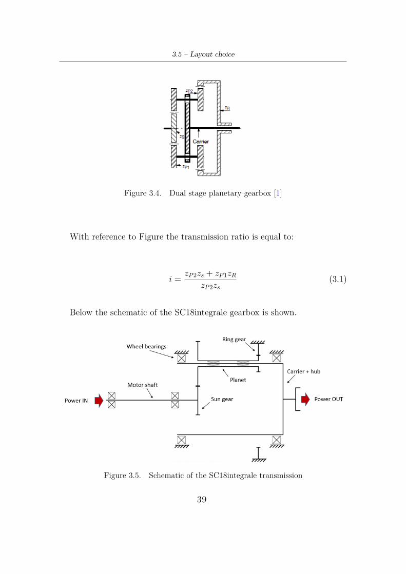
3.5 Layout choice
Aiming to reduce as much as possible the volume hence the weight of thegearbox it is apparent the advantage of the choice of a planetary gearbox.Anyway, by using a single stage planetary gearbox the volume of the trans-mission remains unacceptable for this project’s purpose.
In order to minimize the volume of the gearbox it was chosen to use adual stage planetary layout, with the input on the sun shaft, the output onthe planetary carrier and the ring gear fixed to the case. Basically the sungear transmits the motion to the first stage planet gears that are on the sameshaft of the second stage planet gears, the latter meshing with the ring gearthat is fixed to the case. The output of the gearbox is the planetary carrier.
38
3.5 – Layout choice
Figure 3.4. Dual stage planetary gearbox [1]
With reference to Figure the transmission ratio is equal to:
i = zP2zs + zP1zRzP2zs
(3.1)
Below the schematic of the SC18integrale gearbox is shown.
Figure 3.5. Schematic of the SC18integrale transmission
39

3 – Project Set-Up
3.6 Meshing rule
When evaluating the various gears combination that satisfy the transmissionratio it must be taken into account that not every combination of gears canbe assembled, especially for what concerns a double stage layout.
In order to guarantee the proper assembly, the number of teeth of all thefour gears must respect the following rule:
zSzP2 − zRzP1
Pη= k (3.2)
Where:
• z the number of teeth are already defined in Section 3.5;
• P is the maximum common divisor between zp1 and zp2;
• η = 3 is the number of planet gears;
• k is an integer number.
It must be noticed that it can physically impossible to assemble the gearseteven though the meshing rule is not respected, in particular if the teeth havelarge backlash. This is anyway not desirable because it brings to a wrongmeshing condition, strongly impairing the load sharing between the gears,thus causing high reaction forces.
Finally, in order to guarantee the proper meshing, the three planetarygears couples must be phased equally.
40

3.7 – Load spectrum and required service life
3.7 Load spectrum and required service life
The power and torque demand of a Formula Student vehicle is very irregularduring its duty life, for this reason sizing the mechanical components and inparticular the gear wheels on the maximum load condition can bring to anunnecessary weight on the parts. Also, the torque can be either positive andnegative due to the regenerative braking implementation.
For the abovementioned reasons is important to implement the calcula-tions based on a reference load spectrum, that is iterated through the servicelife. The load spectrum used to develop the calculations regarding the gearlife is extracted from an Autocross event, that is the most demanding workingcondition for the vehicle.
Figure 3.6. Example of load spectrum, showing both the front and therear requested motor torque
41
3 – Project Set-Up
From the graph shown is clear that the most stressed axle is the rear one(statistically the stress between the wheels of the same axle is equally dis-tributed). This difference is mainly due to the fact that the vertical load onthe front wheels is never enough to allow them to transfer the whole torqueavailable to the ground. The scenario just described is clearly more appar-ent in traction conditions, where the overall weight balance that is slightlytowards the rear axle and the load transfer brings to a large difference in thevertical load during acceleration.
During braking condition the weight transfer is towards the front axle andespecially during hard braking, it allows the wheels to transfer a significanttorque to the ground, however this condition doesn’t make the front axle themost critical for gears sizing because the hydraulic brake torque is the maincontributor to the overall brake torque (not the regenerative one), also inorder not to impair too much the driver pedal feedback, the setting of theregenerative braking most of the times doesn’t exploit the full capabilities ofthe electric motor.
Even though it could be possible to adopt two different transmission sizingbetween the front and the rear axis by downsizing the front ones, it was de-cided to realize only one type of gearbox for all the wheels is order to reducethe complexity of the project, given also the tight timeline of a project likethat. Also the spare parts management is far easier by having only one typeof gearbox.
42

3.7 – Load spectrum and required service life
Figure 3.7. Front transmission load spectrum
Figure 3.8. Rear transmission load spectrum
43

3 – Project Set-Up
The required service life is estimated due to the unavailability of some logfiles of the SCdiciassette. Based on previous experiences and estimations aFormula Student vehicle life is subdivided in the following way.
• Races: 105 km (3 races each season, with an average of 35 km)
• Pre-seasonal test: 400 km;
• Mid-seasonal test: 300 km;
• Post-seasonal test: 600 km.
This results in an expected life that can be approximated to 1 500 km.Due to the fact that the average velocity of a Formula Student vehicle isaround 40 km/h the required duty life expressed in hours is 37.5 h, beingrounded up to 40 h for this project’s purpose.
In conclusion, the whole gear set is sized on the iteration of a rear wheelload spectrum for 40 h.
3.8 Design flow
After the targets are set, the transmission ration and the layout are chosenand the duty life with the load requirements are defined, the design of thegearbox can start. The process follows the logical path defined in the figurebelow.
44

3.8 – Design flow
Figure 3.9. Design flow
45

46

Chapter 4
Transmission model
4.1 Introduction to KISSsys
The software used to model the transmission is KISSsys, that is a moduleof the software KISSsoft. KISSsoft is a popular software used for the sizingand the design of various mechanical components, from the a pair of meshinggears to shafts, bearings, springs and a lot of other components.
KISSsys is used to model more complex systems for example completetransmissions. In practice the full system is modelled into the KISSsys suite,while the calculations are performed by different KISSsoft sub-models re-called by the main KISSsys model. The common planetary geartrain has adevoted module in the KISSsoft suite with the characteristics of the gearboxare effectively modelled. A dual stage layout like the one described in theprevious section should be then modelled in the KISSsys suite.
47

4 – Transmission model
Figure 4.1. KISSsys model 3D view
4.2 SC18integrale transmission model
As already described in the previous section, the transmission layout is dualstage, with input on the pinion shaft, output on the planetary carrier andthe ring gear fixed.
Below is described how this sort of gearbox is modelled in KISSsys suite.
4.2.1 Elements involved
In this section all the elements involved in the SC18integrale gearbox modelare described briefly. In the following section the model build with all thespecifications will be described in detail.
• Coaxial shafts: assembly of shafts sharing the same rotation axis;
• Shaft: general shaft, can be the support for different elements;
48

4.2 – SC18integrale transmission model
• Helical gear: representing a meshing gear (not bevel);
• Support: general support, constrains one of more degrees of freedom;
• Coupling: general coupling between different elements;
• Planet carrier coupling: coupling devoted to planetary gears;
• Speed or force constraints: constrains the speed, the torque or both ofan element;
• Carrier-pin connection: connection between the planetary carrier andthe planet pin shaft of an epicycloidal gear system;
• Connection roller bearing: bearing connecting two elements involved inthe model, two parameters must be specified as an input, the inner andthe outer race of the bearing;
• Coaxial shaft calculation module: sub-module in KISSsoft suite thatcarries the shaft calculation in terms of resistance, deformation, etc. . . ;
• Gear pair calculation module: sub-module in KISSsoft suite that carriesthe gear pair calculation.
4.2.2 Model build
First of all, the main gearbox folder is created, named “GB” in the tree [10].After the main group is created, all the shafts needs to be added to it beforeadding bearings and cylindrical gears.
49

4 – Transmission model
Figure 4.2. KISSsys model tree
50

4.2 – SC18integrale transmission model
The first coaxial shafts to be created are: the sun shaft (“SunShaft”), thecarrier shaft (“CarrierShaft”) and the ring gear shaft (“RingShaft”). Thesubgroup “Planet” containing the model of the planet shaft needs then to becreated and contained in it the two coaxial shaft representing the pin shaft(“PinShaft”) and the two planetary gears (“PlanetGearBody”).
At this point the various sub-elements must be added to each coaxial shaft.
Starting from “SunShaft” coaxial shaft the following machine elementsmust be added:
• One coupling (“CouplingSun”);
• Two supports (“SunSupport1”, “SunSupport2”);
• One helical gear (“SunGear”).
“RingShaft” coaxial shaft:
• One coupling (“CouplingRing”);
• One support (“RingSupport”);
• One helical gear (“RingGear”).
The coupling between the pin shafts and the planetary carrier occurs with-out velocity slipping and has a devoted type of element in KISSsys suite, the“planet carrier coupling”.
“CarrierShaft” coaxial shaft:
• One coupling (“CarrierCoupling”);
• One planet carrier coupling (“CarrierElement”);
51
4 – Transmission model
• Two supports (“CarrierSupport1”, “CarrierSupport2”).
“PinShaft” coaxial shaft:
• One planet carrier coupling (“CouplingPin”);
• Two carrier-pin connection (“PinShaftSupport1”, “PinShaftSupport2”).
“PlanetGearBody” coaxial shaft:
• Two “helical gears” (“PlanetGear1”, “PlanetGear2”).
After all the elements have been created, the next step is to define theconstraints between those elements:
• Gear meshing constraints between the sun and the first stage planet gearand the second stage planet gear and the ring gear;
• Needle roller bearings connecting the pin shaft to the planet gears;
• Coupling between the planetary carrier and the planet pin shaft.
The element involved in the gear meshing constraint is the “planetary gearpair constraint”. It is important to use it instead of the normal “gear pairconstraint” because it considers the fact that the sun gear and the ring gearsustain three load cycle per each load cycle of a planet gear. In the three thefirst stage “planetary gear pair constraint” between the sun and the planet iscalled “SunPlanet1” while the second stage one is called “Planet2Ring”. Inthe coupling interface the user can choose the configuration of the coupling(sun/planet, planet/ring and planet/planet), gears involved in the coupling,the number of planets and the efficiency of the coupling.
The element used to represent the needle roller bearings between the pinshaft and the planet gears shaft is called “connection roller bearings” and it
52

4.2 – SC18integrale transmission model
allows to choose the two elements to be connected (“CB1” and CB2” in themodel tree).
Finally, the coupling between the planetary carrier and the planet pinshaft is modelled with the coupling constraint. The latter allows to connectwithout slip the in shaft with the planetary carrier.
In order to define the kinematics of the gearbox, it is needed to define theinput element, the output element the element fixed to the case. For all ofthem the element to be selected is the “speed or force input”. This elementallows to choose an element belonging to a coupling a constraining its speed,its torque, or both to a certain amount and it allows to precise if the elementis an input one (driving) or an output one (driven).
In this transmission’s case the input is via the sun shaft that is so con-strained in speed and in torque. It is important to precise that the speed andthe torque entity must be the peak ones, they will be scaled in the calculationmodule according to the load spectrum. Clearly the sun shaft is the drivingelement.
The ring gear is fixed, so its speed must be constrained to 0 rpm. Finally,the output is on the planetary carrier shaft so it must be a non-constraineddriven element.
Below is shown how the diagram appears at this stage of the model, withall the element and constraints described up to now that can be visualized.
53

4 – Transmission model
Figure 4.3. Diagram of the transmission model
4.3 Calculation modules
Different calculation modules can be linked to KISSsys transmission model.For this project the ones involved are described below.
4.3.1 Coaxial shafts calculation
This module offers an interface to model a system of coaxial shafts. Ge-ometrical parameters, materials and load cases can be defined here. It isassociated to each coaxial shafts system present in KISSsys model.
54

4.3 – Calculation modules
Figure 4.4. Main line calculation module
After running the calculation the maximum deflection and the maximumequivalent stress can be visualized along with the bearing data like the staticsafety factor, the minimum service life and the reaction forces. A more de-tailed post-process interface is also present in order to have a more completeoverlook on the results both for the shafts and the bearings. Here differentplots are generated: displacement, bending angle, equivalent stress and soon.
In this model, two systems of coaxial shafts are present:
• Main line: including the sun gear, the planetary carrier and the ringgear
• Planet shaft: including the planetary gears and the pin shaft
55

4 – Transmission model
4.3.2 Gear pair calculation module
The shaft calculation module offers a tool to model a meshing gear pair bymean of its geometry, the production tolerances and the load ratings.
It is associated to the Gear Pair Constraint present in the KISSsys suite.It carries the constraints and the boundary conditions present in the overalltransmission model, for example the number of load cycles per each gear.
Further detail will be discussed in the following section, dedicated entirelyto the gear calculation.
56

Chapter 5
Gear life calculation
5.1 Introduction to KISSsoft
KISSsoft is a software tool able to perform different kinds of calculationsregarding various mechanical components. Just to mention some of them:cylindrical gear pairs, bevel gear pairs, planetary gears, shafts, bearings,splines, etc. All the calculations are carried in an analytical way.
The "cylindrical gear pair" module allows to determine the geometry andverify the resistance to loads of a gear given as an input some geometricalparameters like the centre distance, the number of teeth (so the transmissionratio) and so on. Through different sections of the interface, all the neededinput parameters can be specified.
KISSsoft allows also to find a solution of gear pair size given the loadrating as an input and geometrical boundary constraints. For example therange of normal module or the range of centre distances amongst which thesolution must lie.
57

5 – Gear life calculation
Below the main sections of the "cylindrical gear pair" calculation modelare explained in better.
5.1.1 Basic data
In the “Basic data” section the gear geometrical parameters are given as aninput or they are calculated by the software. Here the normal module, thehelix angle (if any), the centre distance, the number of teeth, the facewidthand the profile shift coefficients can be partially an input for the user andpartially they can be determined by the calculations performed by the soft-ware to match the user requirement.
Other parameters that must be given as input in this section are the gearquality according to ISO 1328:1995, the gears material, the lubricant and thetype of lubrication and are used by the software to perform the calculation.
In general in this section all the main parameters that define the gear arepresent.
5.1.2 Reference profile
In the “Reference profile” sections, as the name suggests, the parametersdefining the reference profile are present. The reference profile can be chosenamongst different norms, one of the most common is the ISO 53:1998 ProfileA, where the dedendum coefficient is set to 1.25, the addendum coefficient isset to 1.00 and the root radius coefficient is set to 0.38. From a manufacturingpoint of view, the “Reference profile section” allows also to generate theprofile of the tool (hobbing cutter or pinion cutter) to be used.
58

5.1 – Introduction to KISSsoft
Figure 5.1. Reference profile [9]
5.1.3 Tolerances
In the “Tolerances” section, the tolerance class of the gears can be chosenamongst different norms and the centre distance tolerance can be specified.Care must be taken because the tolerance class impacts the calculation.
5.1.4 Rating
In the “Rating” section all the data regarding the load cases of the gear pairis present. Power, torque, speed, required service life and application factorKa can be given as input. There is also the possibility to select a load spec-trum or to insert a custom load spectrum.
The calculation method can be selected between ISO, DIN, AGMA stan-dards and so on.
5.1.5 Factors
Finally, in the “Factors” section the user can modify the factors involved intothe calculation. Just to mention some: KA, KHβ, KHα, Z,Y factors.
59
5 – Gear life calculation
5.1.6 Output plots
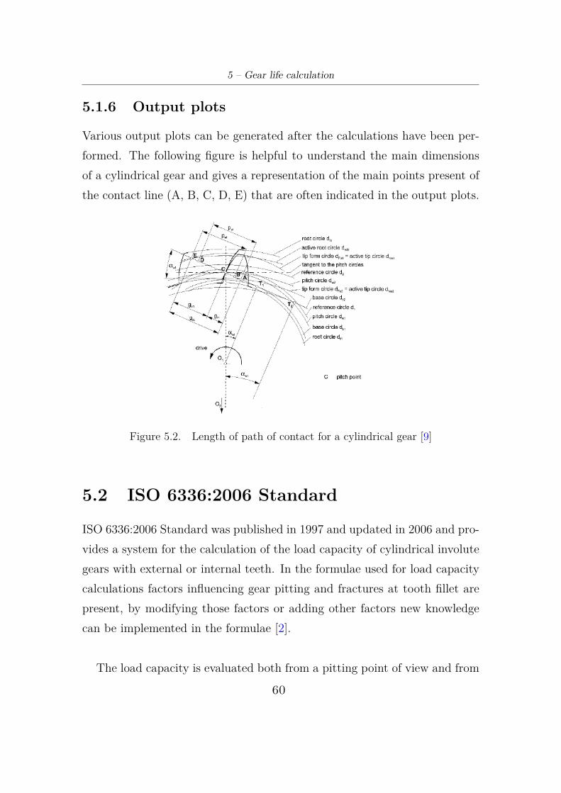
Various output plots can be generated after the calculations have been per-formed. The following figure is helpful to understand the main dimensionsof a cylindrical gear and gives a representation of the main points present ofthe contact line (A, B, C, D, E) that are often indicated in the output plots.
Figure 5.2. Length of path of contact for a cylindrical gear [9]
5.2 ISO 6336:2006 Standard
ISO 6336:2006 Standard was published in 1997 and updated in 2006 and pro-vides a system for the calculation of the load capacity of cylindrical involutegears with external or internal teeth. In the formulae used for load capacitycalculations factors influencing gear pitting and fractures at tooth fillet arepresent, by modifying those factors or adding other factors new knowledgecan be implemented in the formulae [2].
The load capacity is evaluated both from a pitting point of view and from
60

5.2 – ISO 6336:2006 Standard
a tooth breakage point of view. Consequently two different safety factors areconsidered: SH is the one relative to pitting and SF the one relative to toothbreakage. The safety factor is defined as:
Safetyfactor = Modified allowable stress number
Calculated stress(5.1)
The allowable stress number is "modified" due to the corrective factorsdiscussed before.
Three different calculation methods are considered by this standard [2]:
• Method A: factors involved in the calculations are derived from full-scale load tests, precise measurements or comprehensive mathematicalanalysis of the transmission system on the basis of proven operatingexperience, or any combination of these. This method can be the mostaccurate one but it is seldom used due to less research with respect tomethods B and C and a large and costly experimental plan is required;
• Method B: factors are derived with sufficient accuracy for most appli-cations, assumptions involved in their determination are listed. In eachcase, it is necessary to assess whether or not these assumptions apply tothe conditions of interest. This is the most commonly used method;
• Method C: calculation based on simplified assumptions for some fac-tors, assumptions under which they are determined are listed. On eachoccasion an assessment should be made as to whether or not these as-sumptions apply to the existing conditions. Its accuracy is lower withrespect to method B.
"Experimental investigations ([5] and [6]) has proven that ISO 6336 stan-dard is not accurate for modules below 5mm because it tends to underesti-mate the strength of the tooth as the module is reduced. The calculation
61

5 – Gear life calculation
method involves factors which purpose is to take into account the size ofgears only if the module is increased, but no standard rules are defined formodule decrease. Cited research have proven that teeth in gears with finemodule may be even 30% stronger than predicted by the calculation andeven a correction factor of 1.29 has been proposed in [6] for carburized gearswith mn=1.0 mm" [21].
The standards is not updated at the moment of writing and since thecalculation is based on it, the results obtained can be considered rather con-servative.
5.2.1 Pitting load capacity
The pitting stress is in general given by [2]:
σH = A1
óFtd b
u+ 1u
(5.2)
From this, the permissible contact stress can be computed:
σHP = A2σHlimσHmin
(5.3)
Where:
• A1, A2 are products of various factors;
• u is the gear ratio;
• b is the facewidth;
• d is the gear reference diameter;
• Ft is the nominal tangential load;
• σHlim is the maximum allowable pitting stress;
• σHmin is the minimum required pitting safety factor.
62

5.3 – Material choice
5.2.2 Fracture load capacity
The fracture stress is in general given by [2]:
σH = B1Ftb mn
(5.4)
From this, the permissible fracture stress can be computed:
σFP = B2σFlimσFmin
(5.5)
Where:
• B1, B2 are products of various factors;
• mn is the normal module;
• b is the facewidth;
• Ft is the nominal tangential load;
• σFlim is the maximum allowable fracture stress;
• σFmin is the minimum required fracture safety factor.
5.3 Material choice
The main target of this project is to reduce the weight and the volume ofthe gearbox. One way to drastically reduce the weight is to change materialwith respect to SCdiciassette transmission so switching from steel alloys toaluminium or titanium alloys or even to plastic gears.
An analysis regarding the usage if aluminum alloys was performed on thefirst stage gears (meshing between the sun gear and the first planet gear)
63
5 – Gear life calculation
giving the load rating conditions as an input and evaluating the various so-lutions proposed.
The material chosen for this analysis is the only aluminum alloy present inthe software database, whose main properties are listed in the table below.
EN AW AlSi1MgMnT4Material type Wrought aluminum
Type of treatment UntreatedSurface hardness 65.0 HBWCore hardness 65.0 HBW
Rm 205.0 MPaRp 205.0 MPaE 80000.0 MPa
σFlim 160.0 MPaσHlim 260.0 MPa
Table 5.1. EN AW AlSi1MgMnT4 properties [2]
Below two scatter plots are shown: on both plots SHmin (minimum rootsafety between the two gears) is represented on the X axis and SHmin (mini-mum flank safety between the two gears) is represented, while in the first plotthe normal module is color scaled and in the second plot the centre distanceis color scaled.
64

5.3 – Material choice
Figure 5.3. Solutions for aluminum gears scattered as a function ofthe normal module
Figure 5.4. Solutions for aluminum gears scattered as a functionof the centre distance
In order to achieve both SHmin and SHmin close or equal to 1 it is ap-parent that the volume of the transmission resulted even larger with respectto SCdiciassette one, becoming unacceptable for the project. Clearly withplastic gears, this situation is even worse.
65

5 – Gear life calculation
Moreover, the gear manufacturer involved in the project has a large expe-rience with steel alloy gears and heat treatments thus driving the materialchoice amongst steel alloys.
Having chosen to use steel alloys to produce the gears, it is beneficial touse the most performing alloy available in order to maximize the resistanceof the components and consequently to minimize the material in the gear.
Figure 5.5. Properties comparison of case-hardening steels commonlyused for gears manufacturing
EN 17NiCrMo6-4 (UNI 18NiCrMo5) carburized is chosen for all the ex-ternal gears (pinion, planet gears) because of its properties and because islargely available between gears suppliers. In the table below its propertiesare shown.
66

5.3 – Material choice
17NiCrMo6-4Material type Case-hardening steel
Type of treatment Case-hardenedSurface hardness 61.0 HRCCore hardness 325.0 HBW
Rm 1200.0 MPaRp 850.0 MPaE 206000.0 MPa
σFlim 460.0 MPaσHlim 1500.0 MPa
Table 5.2. 17NiCrMo6-4 properties [2]
As shown in the graph reported below, the temperature at which the exter-nal gears are case-hardened is elevated (around 870 °C in this example), thuscausing substantial distortions of the material and requiring consequently tobe grinded after the heat treatment in order to make to tooth profile respectthe tolerances imposed.
Figure 5.6. Nominal time and temperature requirements fordifferent case depths [3]
67

5 – Gear life calculation
It is apparent that in order to have a uniform durability of the gears interms of pitting safety factor, it is necessary to have all the gears with a sim-ilar surface hardness. Not all the manufacturers are indeed capable to grindan internal gear, in this case, this process was impossible to be executed onthe ring gear.
Nitridation instead is a process that occurs at lower temperatures, avoidingthe gear to be grinded after the heat treatment. As a reference in the tablebelow the parameters regarding AISI 4140 steel (EN 42CrMo4) are shown,the nitriding temperature (around 524 °C) is substantially lower with respectto the carburizing temperature.
Steel Nitriding temperature Case hardness Core hardnessAISI 4140 975 °F 49-54 HRC 27-35 HRC
Table 5.3. Nominal temperatures used in nitriding and hardness obtained [3]
For the reasons mentioned above, the ring gear is decided to be nitrided af-ter cutting without being grinded after the heat treatment. Clearly the samequality and the same tolerances of the grinded gears cannot be achieved forthe ring gear.
Initially 34CrAlNi7-10 was chosen because the surface hardness reachableafter the heat treatment is very high and it is really similar to the othergears. Below the properties of the mentioned material are shown.
68

5.4 – Calculation set-up
34CrAlNi7-10Material type Nitriding steel
Type of treatment Gas-nitridedSurface hardness 950.0 HVCore hardness 950.0 HV
Rm 800.0 MPaRp 600.0 MPaE 206000.0 MPa
σFlim 425.0 MPaσHlim 1250.0 MPa
Table 5.4. 34CrAlNi7-10 properties [2]
Although optimal for the calculations carried, this material was unavail-able for the manufacturer of the gears so the choice was forced on 42CrMo4steel nitrided. In the table below its properties are shown.
42CrMo4Material type Through hardening steel
Type of treatment NitridedSurface hardness 550.0 HVCore hardness 210.0 HBW
Rm 1100.0 MPaRp 900.0 MPaE 206000.0 MPa
σFlim 370.0 MPaσHlim 1000.0 MPa
Table 5.5. 42CrMo4 properties [2]
5.4 Calculation set-up
As seen in 5.3, the material chosen is 17NiCrMo6-4 carburized for all theexternal gears and 42CrMo4 nitrided for the ring gear.
69

5 – Gear life calculation
It was chosen to have a pressure angle of 20° (SCdiciassette gears had apressure angle of 25°) because it is beneficial both for efficiency and manu-facturing reasons. It must be noticed that it was decided to increase by thefacewidth of the driving wheels (and also the smaller ones), i.e. the sun gearand the second stage planet gears, with respect to the driven gears. Thisaiming to ensure that the minimum facewidth computed is always in contactin order to avoid a reduction of the contact surface under load.
The quality level according ISO 1328:1995 is set to 5 for all the externalgears, having discussed with the manufacturer that is possible to achieve thislevel of quality for grinded gears. The ring gear cannot be grinded with themanufacturer’s equipment, so its quality level is set to 7. This parametermust be chosen carefully after knowing what the capabilities of the manu-facturer are because its impact on the calculation is significant.
The oil chosen is the ISO-VG 68 (the lubrication topic will be dealt inmore detail in Section 9) and the lubrication is set to be “oil bath lubrica-tion” according to the real working condition of the gearbox.
The reference profile chosen is the ISO 53:1998 Profile A, where the de-dendum coefficient is set to 1.25, the addendum coefficient is set to 1.00 andthe root radius coefficient is set to 0.38.
The tooth thickness tolerance is set according to the class 3967 cd25, thataccording to Niemann proposal is suitable for standard machine parts witha module 0.5 mm < 3 mm.
For this project the load condition is given by the load spectrum discussedin Section 3.7 that scales the peak input values of 21 Nm torque and 20000rpm speed per each time step. The required service life has been set to 40 h.
70

5.4 – Calculation set-up
Moreover, due to the detailed knowledge of the load history of the gearboxand due to its low possibility to vary from those conditions, the applicationfactor KA has been set to 1.0.
Finally, the following considerations has been made regarding the correc-tive coefficients:
• Dynamic factor KV : calculated by the software through the load spec-trum data per each voice of the latter;
• Transverse load factor KHα: calculated by the software through the loadspectrum data per each voice of the latter;
• Face load factor KHβ: calculated according to ISO 6336 by the softwaregiving as input the type of pinion shaft and the tooth trace modification(if any);
• Alternating bending factor (mean stress influence coefficient) YM : cal-culated for an oscillating stress.
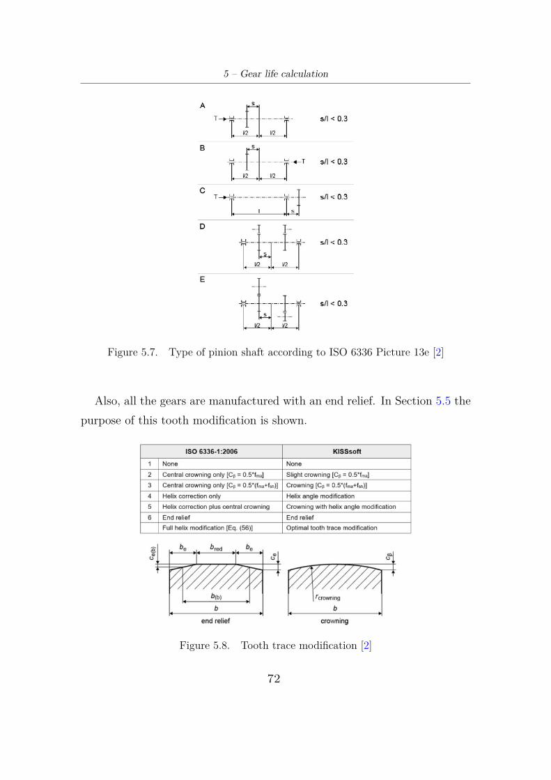
Regarding KHβ coefficient calculation, the pinion type is different betweenthe two stages. In particular, according to Figure 5.7:
• 1st stage: C;
• 2nd stage: E.
71
5 – Gear life calculation
Figure 5.7. Type of pinion shaft according to ISO 6336 Picture 13e [2]
Also, all the gears are manufactured with an end relief. In Section 5.5 thepurpose of this tooth modification is shown.
Figure 5.8. Tooth trace modification [2]
72

5.4 – Calculation set-up
Regarding the alternating bending factor calculation YM , with referenceto Figure 5.9 and considering and average oscillating cycles number of 210per the sun gear and of 70 for the second planet gear the following equationis used [7].
YM = 0.85 − 0.20 log(Nrev)6 (5.6)
Giving the following results:
• YM = 0.773 for the first stage;
• YM = 0.788 for the second stage.
Figure 5.9. Alternate load factor determination [9]
73

5 – Gear life calculation
5.5 Results
5.5.1 Final geometry definition
After some calculation loops, the following solution resulted to be the onethat matched more all the targets imposed.
First stageNormal module mn 0.8 mm
Pressure angle at normal section αn 20°Centre distance a 33.8 mm
Gear 1 Gear 2Number of teeth z 21 63
Facewidth b 11.0 mm 10.0 mmProfile shift coefficient x∗ 0.3500 -0.0945Quality (ISO 1328:1995) Q 5 5
Material 17NiCrMo6-4 17NiCrMo6-4
Table 5.6. First stage data
Under load the tooth is deformed and its profile is not an involute anymore,also the profile is changed from the ideal one due to manufacturing errorsand the teeth in contact can be one or two (the latter for most of the time) [8].
Profile modifications tip relief aims to reduce the irregularity of the loadsacting on the gear during meshing (i.e. the transmission errors), achievinga more regular meshing is beneficial both from noise and resistance point ofview. One possible profile modification is the tip relief. Tip relief on thedriven gear reduces the entry impact, whereas tip relief on the driving gearreduces the exit impact. Tip relief is therefore usually applied to both gears[9].
74

5.5 – Results
Figure 5.10. Tip and root relief [8]
The optimal tip relief can be computed by KISSsoft according to variousmethods, in this case the linear method has been chosen and the a tip reliefof 8µm (Ca in Figure 5.10) with a length of 7µm (LCa in Figure 5.10) isobtained for the first stage gears, also a 0.2 mm chamfering of the tooth endis proposed. Below the plot of the normal forces acting on the tooth flankon the first stage gears both with and without end relief modification areshown, the smoothness difference is apparent.
Figure 5.11. First stage without (left) and with (right) tip relief modification
75

5 – Gear life calculation
Figure 5.12. Fist stage meshing gears
Second stageNormal module mn 0.8 mm
Pressure angle at normal section αn 20°Centre distance a -33.8 mm
Gear 1 Gear 2Number of teeth z 24 -108
Facewidth b 17.0 mm 16.0 mmProfile shift coefficient x∗ 0.4976 -0.7531Quality (ISO 1328:1995) Q 5 7
Material 17NiCrMo6-4 42CrMo4
Table 5.7. Second stage data
Also for the second stage the linear method has been chosen and the a tiprelief of 11µm (Ca in Figure 5.10) with a length of 10µm (LCa in Figure 5.10)is obtained, also a 0.2 mm chamfering of the tooth end is proposed. In thefollowing, as for first the first stage, also for the second stage are shown theplots of the normal forces acting on the tooth flank both with and withoutend relief modification are shown.
76

5.5 – Results
Figure 5.13. Second stage without (left) and with (right) end relief modification
Figure 5.14. Second stage meshing gears
The transmission ratio obtained is 14.8:1, that is close to the target oneof 15:1.
77

5 – Gear life calculation
5.5.2 Life calculation results
First stage
Below the safety factors for the first stage are shown. Even though in Section5.2 it was explained that for small module gears ISO 6336:2006 calculationmethod is conservative, a safety factor above one is considered acceptable.
First stage safety factorsGear 1 Gear 2
Root safety 2.7 2.3Flank safety 1.5 1.8
Table 5.8. First stage safety factors
Below the specific sliding for the first stage is shown.
Figure 5.15. First stage specific sliding
Also the root stress plots under maximum torque are shown below for thefirst stage gears.
78

5.5 – Results
Figure 5.16. Root stresses for the sun gear (left) and for the first planet gear(right) under maximum torque
Finally, the hardness curve recommendation along the distance from thesurface is shown.
Figure 5.17. First stage hardness curve recommendation
Second stage
Below the safety factors for the second stage are shown. The target was tohave all the safety factors above 1 and the only gear that doesn’t respectthat condition is the ring gear, but due to the fact that its safety factor isquite close to 1 (0.9) and having said in Section 5.2 that the the normativeis quite conservative, the result is anyway acceptable.
79

5 – Gear life calculation
Second stage safety factorsGear 1 Gear 2
Root safety 1.9 1.6Flank safety 1.7 0.9
Table 5.9. Second stage safety factors
Below also the specific sliding for the second stage is shown. The conditionis clearly less favourable with respect to the first stage one because beingforced to maintain the same centre distance between the two stages doesn’tallow to optimize the specific sliding for both the stages.
Figure 5.18. Second stage specific sliding
The root stress plots under maximum torque are shown below for thesecond stage gears.
80

5.5 – Results
Figure 5.19. Root stresses for the second planet gear (left) and for the ringgear (right) under maximum torque
Finally, the hardness curve recommendation along the distance from thesurface is shown.
Figure 5.20. Second stage hardness curve recommendation
81

82

Chapter 6
Wheel bearings
6.1 Layout and bearing choice
As seen in Section 3.5 the planetary carrier and output shaft of the geartrain is also the wheel hub. For this reason, the bearings connecting theplanetary carrier to the upright (i.e. the transmission case) are indeed thewheel bearings. Obviously, a stiff assembly is ideal for the wheel operation,both in the radial direction and the axial direction.
As in most of wheel bearings application, two oblique bearings in the “O”mount configuration have been chosen. Oblique bearings can sustain largeaxial loads along with the radial loads. Moreover, due to the oblique ballraceways, the reaction points on the wheel axis are shifted with respect tothe bearing mid plane. “O” mount bearings offers the stiffest mount becausethe reaction point on the wheel axis are more spaced with respect as if thebearings were common radial bearings.
83

6 – Wheel bearings
Figure 6.1. SC18integrale wheel bearings layout
SC17 also features “O” mount oblique wheel bearings are 71820 CD/HCP4,manufactured by SKF. Below the characteristics can be seen with referenceto Figure 6.2.
Figure 6.2. Main dimensions for bearings of the type ACD,CD [11]
84

6.1 – Layout and bearing choice
Main dimensions Load coefficients Maximum velocity Massd A B C C0 Oil-air lubrication
mm kN rpm kg100 125 22.5 29 11 17 000 0.28
SKF 71820 CD/HCP4 bearing characteristics [11]
The bearings have a ceramic spheres that brings to a weight reduction of30 g per each bearing with respect to the same bearing with steel spheres(71820 CD/P4). The ceramic spheres solution offers the possibility to oper-ate at higher rotational speeds.
In the transmission discussed in this work the centre distance is 33.8 mm(as determined in Section 5.5) so the bearings external diameter can be signif-icantly reduced from a package point of view. Dimensions-wise the smallestbearings compatible with this assembly is SKF 71816 ACD/P4. This bearingis taken from the Super-precision catalogue because in the common obliquebearings catalogue all the bearings have larger dimensions.
Main dimensions Load coefficients Max velocity Massd A B C C0 Oil-air lubric.
mm kN rpm kg80 100 10 13.8 17 17 000 0.15
SKF 71816 ACD/P4 bearing characteristics [11]
The same bearing with the ceramic spheres instead of the steel ones iscalled SKF 71816 ACD/HCP4 and it has the same load rating but a max-imum admissible velocity of 20 000 rpm with oil-air lubrication and a massof 0.14 kg.
85

6 – Wheel bearings
For the SC18intergale project it was decided not to use the bearing withceramic spheres because the hub peak rotational speed is around 1 350 rpm,so the steel spheres offers a speed rating that is more than enough and theweight reduction (10 g) is not significant for this application. The bearingwith the steel spheres is available from the manufacturer with a much lowerlead time.
With respect to SCdiciassette wheel bearings a weight saving of 0.13 kgper each bearing so 0.26 kg per vehicle corner is achieved.
6.2 Bearings life calculation
The wheel bearings sizing has been done in collaboration with SquadraCorse’s long partner and supplier SKF. The load spectrum at the tire contactpatch has been supplied by Squadra Corse to SKF, that carried the bearingslike calculation.
6.2.1 Load spectrum
Below the load spectrum of the forces in all the three directions is shown.This load spectrum is extracted from a log file relative to an Autocross event,the most demanding in terms of required power and peak accelerations.
86

6.2 – Bearings life calculation
Figure 6.3. Fx load spectrum where Fx >= 20 N
Figure 6.4. Fx load spectrum where Fy >= 20 N
87

6 – Wheel bearings
Figure 6.5. Fz load spectrum
6.2.2 Life calculation results
The purpose of the calculation carried is to determine the life of the bearingsassembly and to determine which is the axial preload that maximizes thebearings’ life. Obviously, the details of the calculation are not disclosed bySKF, for this reason below only the results are reported.
88

6.2 – Bearings life calculation
Figure 6.6. Wheel bearings life as a function of axial preload [14]
In the first plot the fatigue life versus the preload values is plotted. Themost stressed wheel resulted to be the rear one with a life of around 4 300Mrevs, while the predicted life of the front wheel is 6 500 Mrev. Consideringthe estimated life of 1 500 km (Section 3.7) and the loaded rolling radius of236.5 mm, the required life for the wheel bearings is around 1 MRev, thusthe predicted life of the wheel bearings is acceptable.
This plot underlines the importance that a proper preload has on the bear-ing’s life. For this application a value of 15 µm is chosen.
In the following plots the peak contact load is plotted for the internal andexternal bearings for both the front and the rear wheels, with 15µm preload.
89

6 – Wheel bearings
Figure 6.7. Front peak contact loads on the external bearing (left) and onthe internal bearing (right) [14]
Figure 6.8. Rear peak contact loads on the external bearing (left) and onthe internal bearing (right) [14]
6.3 Axial preload
In the previous section the large influence that the axial preload of a bearingassembly has on the bearings life has been showed quantitatively. It must bethen carefully regulated because it can impact significantly on the bearinglife.
90
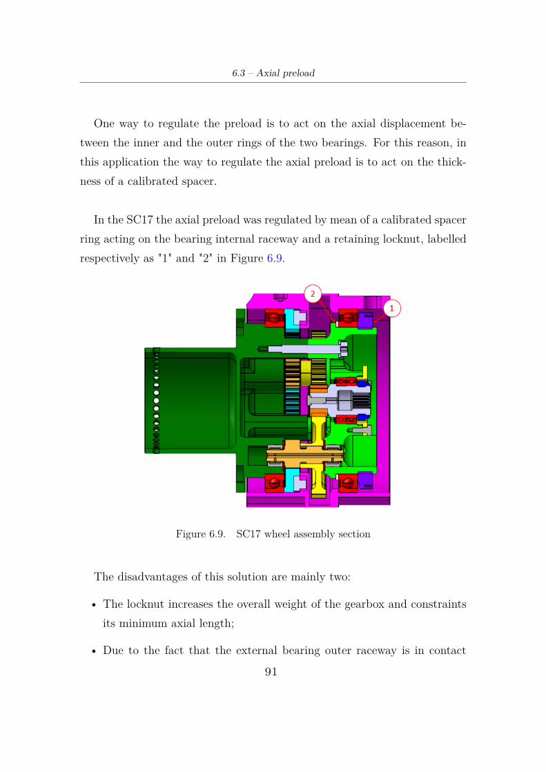
6.3 – Axial preload
One way to regulate the preload is to act on the axial displacement be-tween the inner and the outer rings of the two bearings. For this reason, inthis application the way to regulate the axial preload is to act on the thick-ness of a calibrated spacer.
In the SC17 the axial preload was regulated by mean of a calibrated spacerring acting on the bearing internal raceway and a retaining locknut, labelledrespectively as "1" and "2" in Figure 6.9.
Figure 6.9. SC17 wheel assembly section
The disadvantages of this solution are mainly two:
• The locknut increases the overall weight of the gearbox and constraintsits minimum axial length;
• Due to the fact that the external bearing outer raceway is in contact
91

6 – Wheel bearings
with the ring gear, preloading the bearing assembly also gives an axialpreload to the ring gear, thus fixing it and avoiding it to float. Thisis not beneficial for the meshing with the planetary gears, as it will bebetter discussed in Section 7.2.
In the SC18integrale layout, the locknut has been removed and the bear-ing is kept in position by the screws that retain also the planetary carrier tothe hub, as shown in Figure 6.10. The preload ring is the one highlighted inorange in the same picture.
Figure 6.10. SC18 wheel bearings preload
The preload ring must be calibrated during the assembly of each cornerbecause the bearing life is so sensitive to the variations in preload that any
92

6.3 – Axial preload
chain of tolerances developed will result to be inadequate. In particular,referencing again Figure 6.10, the thickness of the preload ring is given bythe following equation.
s = B − A− p (6.1)
Where:
• B, A are measured during the assembly
• p is the target preload, determined in Section 6.2
93

94

Chapter 7
Mechanical design of geartrain components
7.1 Sun gear
7.1.1 Component engineering
Below a section view of the SCdiciassette geartrain pinion shaft.
Figure 7.1. SC17 sun shaft
95
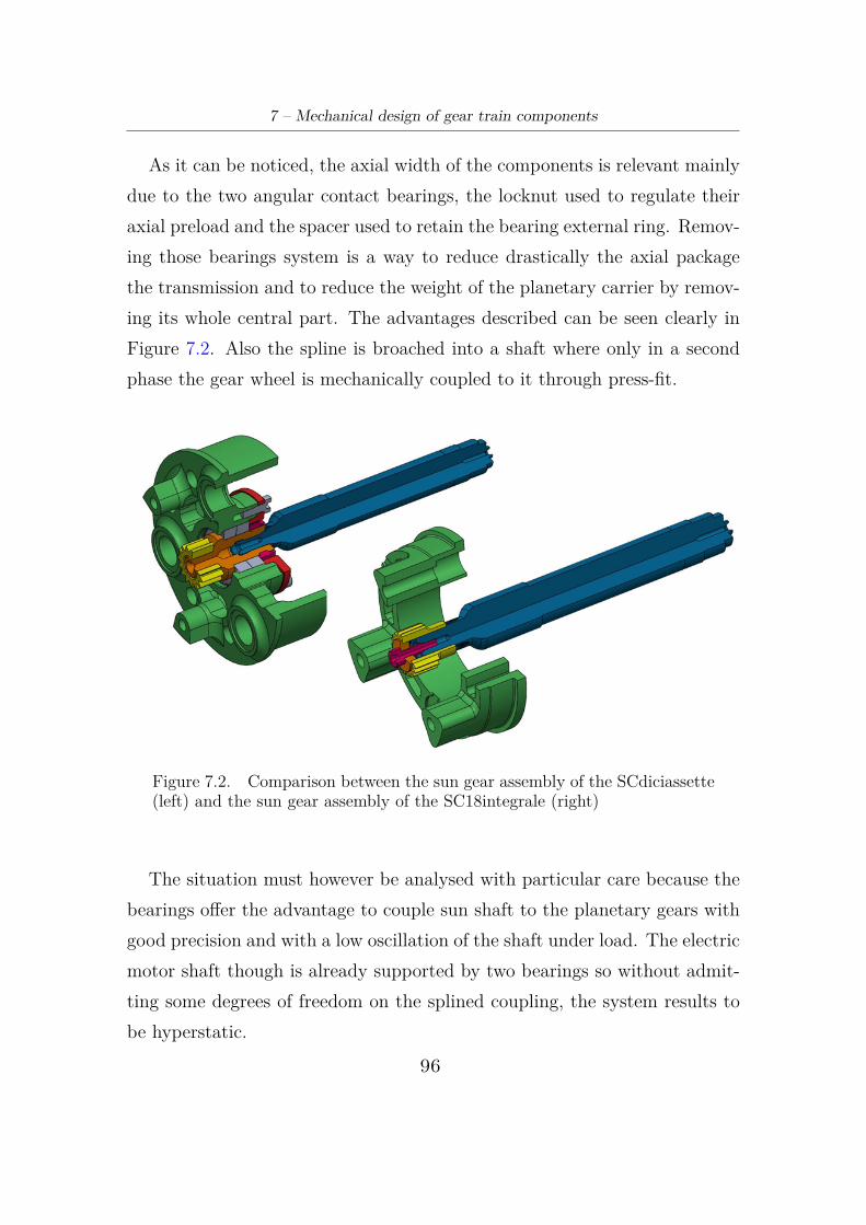
7 – Mechanical design of gear train components
As it can be noticed, the axial width of the components is relevant mainlydue to the two angular contact bearings, the locknut used to regulate theiraxial preload and the spacer used to retain the bearing external ring. Remov-ing those bearings system is a way to reduce drastically the axial packagethe transmission and to reduce the weight of the planetary carrier by remov-ing its whole central part. The advantages described can be seen clearly inFigure 7.2. Also the spline is broached into a shaft where only in a secondphase the gear wheel is mechanically coupled to it through press-fit.
Figure 7.2. Comparison between the sun gear assembly of the SCdiciassette(left) and the sun gear assembly of the SC18integrale (right)
The situation must however be analysed with particular care because thebearings offer the advantage to couple sun shaft to the planetary gears withgood precision and with a low oscillation of the shaft under load. The electricmotor shaft though is already supported by two bearings so without admit-ting some degrees of freedom on the splined coupling, the system results tobe hyperstatic.
96

7.1 – Sun gear
In order to decide whether to maintain the bearings or not, a detailedanalysis of the geometric oscillations of the motor output shaft due to pro-duction tolerances and an analysis of the oscillations under load has to becarried. Those aspects will be dealt in detail in Sections 7.1.2 and 7.1.3.
Removing the bearings means also to have the planetary carrier and thesun wheel closer to the motor mounting flange. Due to the proximity of theplanetary carrier to the motor mounting flange, countersunk screws needsto be used to retain the motor to its mounting flange in order to avoidinterferences.
Figure 7.3. Motor mounting flange detail
The output of the electric motor shaft is a male spline (DIN 5480 - W11x 0,8 x 30° x h8), schematically shown Figure 7.4. In order to reduce thevolume of the component and consequently its weight the female spline inthe SC18integrale layout is broached directly into the sun gear (differentlyfrom what shown in Figure 7.2 for the SCdiciassette layout).
97

7 – Mechanical design of gear train components
Figure 7.4. Motor output spline
Finally a retention model for the sun gear to the motor output shaft hasto be found. This can be done in two ways: through a circlip (see Figure7.4) or through a screw (see Figure 7.5).
Figure 7.5. Motor output spline section view
In this application it was impossible to use a circlip due to excessive over-hang of the sun gear, consequently a turned plug and a screw have beenemployed to this purpose, as shown in Figure 7.6. Due to the fact that allthe torque in input and in output of the gearbox is carried by the spline,the screw tightening torque doesn’t have to be sized to carry the transmittedtorque but in any case it is tightened to the maximum sustainable axial load
98

7.1 – Sun gear
for an M4 screw and some threadlocker is used.
Figure 7.6. Sun gear
7.1.2 Geometric oscillations of the motor output shaft
In order to evaluate the precision with which the motor output shaft is manu-factured, two type of measures have been performed: oscillation of the splineroot radius and of the spline top radius from the nominal one, maximumoscillation of the non-splined section.
The measures have been carried using a centesimal dial gauge in a temperature-controlled chamber (Figure 7.7). The gauge is set on the first tip (or the firstroot), whose diameter has been previously measured and the motor shaft isrotated in order to measure the oscillation of all the other tips (or roots)with respect to the reference one. This process is repeated three times andthe measured dimensions are averaged in order to minimize the errors in thereading of the measure.
99
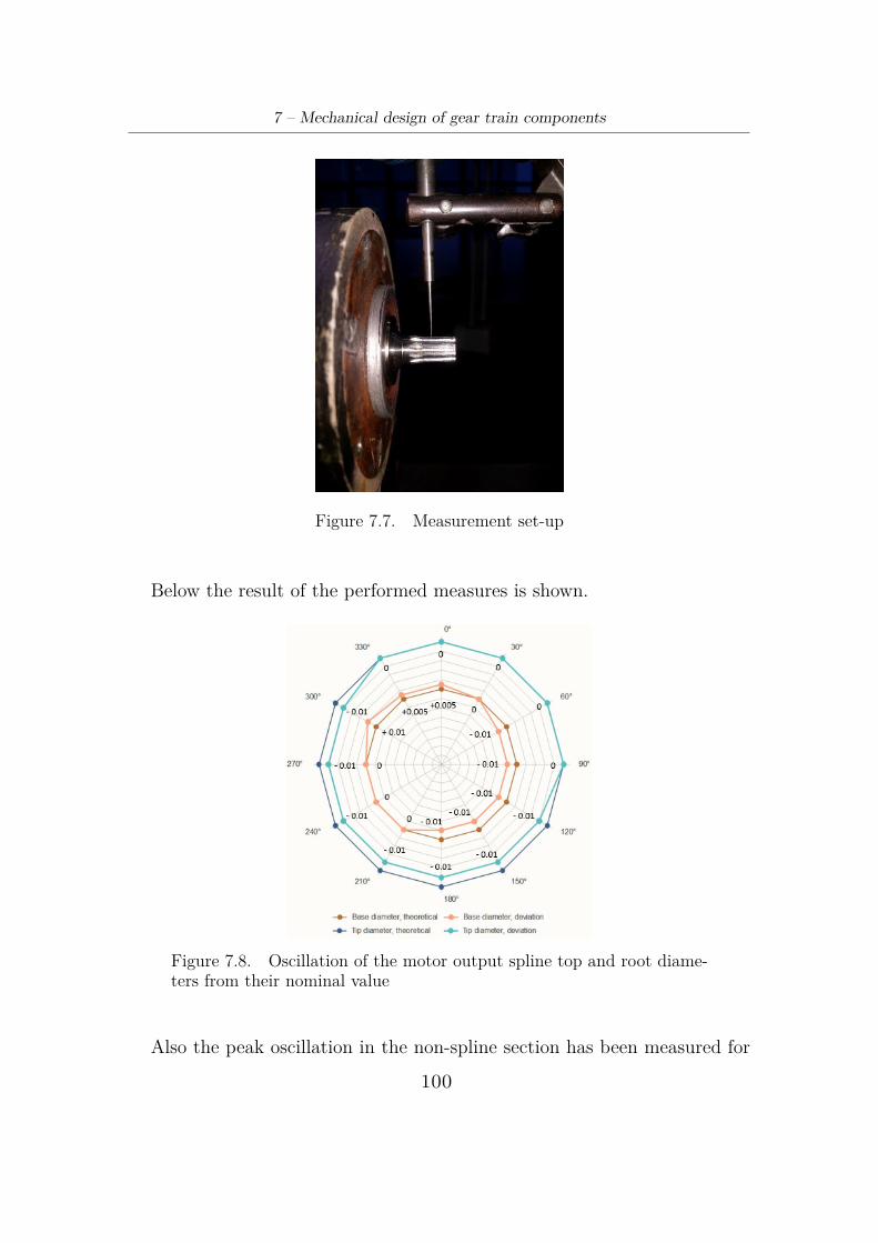
7 – Mechanical design of gear train components
Figure 7.7. Measurement set-up
Below the result of the performed measures is shown.
Figure 7.8. Oscillation of the motor output spline top and root diame-ters from their nominal value
Also the peak oscillation in the non-spline section has been measured for
100

7.1 – Sun gear
reference, resulting to be equal to 0.012 mm.
Figure 7.9. Maximum oscillation of the motor output shaft non-splined section
7.1.3 Analysis of the motor output shaft under load
Theoretically there are not any forces that stress the sun gear shaft (and sothe motor output shaft), this because in the layout with three planetary gearsthe three radial components of the contact forces should balance between eachother and the center of mass of the sun gear lies exactly of the motor outputshaft.
101

7 – Mechanical design of gear train components
Figure 7.10. Radial forces due to meshing gear pairs acting on the sun gear
In the real application those two conditions are not necessarily guaranteed,so to verify the peak deflection of the motor shaft it was assumed that theradial force coming from one meshing pair is totally sustained by the sunshaft and that the centre of mass of the sun shaft has a radius of 0.5 mmwith respect to the motor axis, the latter assumption being conservativebecause the sun gear is balanced after being manufactured. Due to the factthat, as shown in Figure 3.2, at the maximum motor speed of 20 000 rpmthe torque available is around 14 Nm and that the peak torque of 21 Nm isavailable up to 13 000 rpm, the worst between the following two cases mustbe analyzed:
• Maximum motor speed: 134 N of radial force;
• Maximum motor torque: 388 N of radial force.
The worst case scenario is the one at maximum radial torque, so 388 Nis the load against which the motor shaft has to be verified. The system ismodeled in KISSsoft suite.
102

7.1 – Sun gear
Figure 7.11. Model of the motor output shaft in KISSsoft
The resulting peak deflection is 0.036 mm. The deflection plot along theshaft length is shown below.
Figure 7.12. Motor shaft deflection
7.1.4 Manufacturing
The material chosen for the sun gear is 18CrNiMo5 (Section 5.3).
After the rough shape of the component has been turned, the sun gear ishobbed, then the part is carburized. Finally the the gear is finished throughgrinding.
103

7 – Mechanical design of gear train components
Figure 7.13. Carburized case pattern
The case hardening depth is set to 0.3-0.4 mm, this being larger than theminimum one given by the output of the calculation (0.15 - 0.18 mm) andlower with respect to the maximum one given by Equation 7.1. Some extra-material is added in order to take into account the material removed duringgrinding, that is expected to be 0.05-0.1 mm.
hem = 0.40 ∗mn = 0.40 ∗ 0.8mm = 0.32mm (7.1)
Where:
• hem is the maximum case hardening depth;
• mn is the gear normal module.
The latter equation refers to the maximum allowable case depth in theregion C of Figure 7.13 because a too deep case in this region may cause thewhole top of the tooth to break off.
104

7.2 – Ring gear
7.2 Ring gear
7.2.1 Component engineering
In the planetary gear train studied the ring gear is fixed to the case (i.e. theupright) in order to be able to work as a reducer.
The SCdiciassette ring gear is retained to the fixed case by mean of a cam.In order to fit the cam the external ring gear diameter needs to be significantlylarger with respect to the gear pitch diameter (as shown in Figure 7.14) thusimplying the ring gear to be heavy and to require large radial room to beinstalled.
Figure 7.14. SCdiciassette ring gear retention system [22]
In order to avoid those issues, the solution adopted is to machine externalteeth on the ring gear external profile. Two different kinds of tooth profileshave been investigated: curved flank teeth (Figure 7.15, straight flank teeth(Figure 7.17).
105

7 – Mechanical design of gear train components
Figure 7.15. Curved flank teeth solution
In order to guarantee a better contact, the curved flank tooth profile needsrelief grooves to be machined at the tooth root. After some preliminary FEAanalysis it is apparent that this solution causes the external profile stressesto be significantly high.
Therefore, the straight flank teeth solution has been chosen. The straightflank offers a better contact area with the upright. Moreover, there is no moreneed for a relief groove since the contact can occur on the straight flank soat the tooth base a fillet can be present. Obviously, the stresses observed asoutput of the FEA analysis are drastically lower, the teeth number was alsoincreased to reduce further the peak stresses.
Finally, three radial screws with custom calibrated end diameter constrainthe ring gear axially to the upright (Figure 7.16).
106

7.2 – Ring gear
Figure 7.16. SC18 integrale ring gear retention system
The external diameter of the ring gear (not the teeth external diameterhas a nominal value of 96 mm (as the mating bore in the upright) and thecoupling between it and the mating bore is d7-H7, thus a significant radialbacklash exists. This is made to keep the ring gear slightly floating thusaccommodating better production tolerances.
Figure 7.17. Ring gear
107

7 – Mechanical design of gear train components
7.2.2 Structural analysis
Along with the ring gear, also the bore in which the ring gear is modeled andmeshed for this analysis in order to check for potential strains in the upright.A simplified version of the ring gear with only the teeth where the force isapplied is meshed, in order to reduce the computational times.
The bore in which the ring gear fits is fixed in all its degrees of freedom,while the ring gear is allowed to rotate only on its axis. The load transmittedby each gear in peak torque condition is applied to three teeth meshed.Contact surfaces without slip are defined at the contact point between thering gear and the upright in the direction opposing to the load applied.
Figure 7.18. Ring gear FEM model
The most stressed point resulted to be the fillet of a tooth near the loadapplication. Below its contour plot is shown.
108

7.2 – Ring gear
Figure 7.19. Ring gear stress contour plot
The static safety factor against strain is given by the following expression.
SF = Rpσmax
= 900MPa
371.2MPa= 2.4 (7.2)
The latter being acceptable for this purpose.
7.2.3 Manufacturing
The gear toothing is the first machining process to be performed on the ringgear, the outer profile is kept circular from the raw material.
After gear cutting, the ring gear external profile (the one used to con-strain its rotation to the case) is machined. The ring gear in this stage isconstrained to the mill plate through four cylindrical rollers that lies on thegear teeth. The phase that the external teeth have with respect to the inter-nal ones is not relevant but it is fundamental that the external diameter isconcentric with respect to the pitch diameter.
109

7 – Mechanical design of gear train components
Finally, the ring gear is case hardened. As already mentioned, the ringgear is case hardened through nitridation with a case depth of 0.15 mm.The latter case depth being the minimum one imposed by the calculationbecause keeping the depth minimum reduces the heat treatment time asshown in Figure 7.20.
Figure 7.20. Nominal times required for different nitride case depths [3]
Reducing the heat treatment time is helpful to minimize the distortion ofthe component because the ring gear is not reworked after case hardening.
7.3 Planetary gears assembly
7.3.1 Components engineering
In the picture below, a section view of the planet gear assembly can be seen.
110

7.3 – Planetary gears assembly
Figure 7.21. Planetary gears assembly
The two planetary gears (light blue and pink in Figure 7.21) are sepa-rately cutted and then assembled together.This solution is adopted becauseit allows to minimize the axial dimension of the planetary gears. By makingthem from a single piece the room taken by the component would be signifi-cantly higher because the smaller wheel would need some axial relief in orderto allow the tool passage during the gear cutting and the grinding.
In order to have a proper meshing of the gears, the assembly needs allthe planetary gears to be equal to each other, the latter condition comingfrom the meshing requirements discussed in Section 3.6. If not one or twogears may not have a proper meshing or worse, they cannot be assembled,the tight axial backlash between the teeth makes this situation even morecritical and requires more precision in the assembly. The assembly procedurewill be explained better in Section 7.3.6.
111

7 – Mechanical design of gear train components
The purpose of the keyway (grey in Figure 7.21) is not to transmit torquebut to locate one gear with respect to the other, in fact its size is not suitableto transmit the torques involved. Therefore, all the torque transmitted bythe planetary gears is transferred from one gear to the other by means offriction. This topic will be better investigated in Section 7.3.2.
The two planetary gears assembled are connected to the planetary carrierby mean of a shaft (yellow in 7.21) and they are supported onto this shaftthrough two needle roller bearings, axially located by mean of a plastic ring(dark green in 7.21).
The spacers coloured in black in Figure 7.21 are used to avoid that thecarburized gears spin during operation against the planetary carrier and thehub surfaces, damaging them. To this purpose the spacers are retained withan anti-rotation pin (Figure 7.22) to the hub and the planetary carrier byone side, while from the other side they slide against the planetary gears. Inorder to avoid the spacers to damage during operation, their material andthe heat treatment has been properly chosen and some oil passages have beenworked onto their surface. The latter aspect is useful also for needle bearingslubrication purposes.
112

7.3 – Planetary gears assembly
Figure 7.22. Anti-rotation pin in the carrier (left) and spacer (right)
One axial hole and two rows of radial holes are drilled into the planet pinshaft in correspondence of the needle roller bearings midplane. This solutionis aimed to guarantee and oil flow from the case to the bearings along withthe previously described spacers.
Figure 7.23. Planet pin shaft
Finally the planet pin shaft rotation is prevented by the fact that thegroove into the pin shaft visible in Figure 7.23, couples with an H-shapedbushing that is press fitted into the planetary carrier and axially retained bya circlip.
113

7 – Mechanical design of gear train components
Figure 7.24. Planet pin shaft rotational constrain
7.3.2 Torque transmission
The torque transmission between one gear and the other as already mentionedoccurs by friction. This solution has been already successfully adopted in theprevious year’s transmission and it avoids using a keyway that takes a lotmore space. Also, it avoids using splines or other profiles that are difficultto manufacture.
The type of pressure fit has been studies by mean of a devoted KISSsoftsub-module. Giving as an input the dimensions of the two components, thejoint diameter, the length of the fit, the materials of the coupled components,the operational torque and rotational velocity, the friction coefficients, theservice temperatures, the surface finish and the tolerances of the both theshaft and the hub, the software is able to calculate the safety against slidingand the safety against the fracture of both the shaft and the hub.
The diameters with their tolerances of the components involved are:
• Shaft: 17.5 (+0.030/0.035 mm);
• Hub: 17.5 H6 (0/+0.011 mm).
Below the allowances are shown.
114

7.3 – Planetary gears assembly
Figure 7.25. Left display: tolerance field only takes allowances into account,centre display: tolerance field takes into account temperature and centrifugalforce (without pressure), right display: tolerance field takes into accounttemperature, centrifugal force and pressure
Below is shown also the plot of the stresses involved into the press fit.
Figure 7.26. Plot of the stresses of the press fit in the shaft and in the hub
115

7 – Mechanical design of gear train components
7.3.3 Pin shaft structural analysis
KISSsoft model
The deflection and the stresses on the pin shaft have been evaluated in a firststage using the KISSsoft suite. A coaxial shafts model has been developedin KISSsys suite as a part of the main transmission model, where the pinshaft is modelled with two supports in the contact points with the planetarycarrier and the hub.
In this case the two assembled gears were modelled as it was single shafts.As a connecting element between the two shafts, rolling bearings has beenused in order to minimize the radial dimension.
Figure 7.27. Planetary gear assembly model in KISSsoft
The two connecting needle roller bearings are K 8x11x13 TN supplied bySKF. They have 1.5 mm diameter needle rollers and a length of 13 mm [12].The model of those bearings can be found in KISSsoft database so they areeasily added to the calculation.
116

7.3 – Planetary gears assembly
The calculation is performed under maximum torque conditions, belowthe results in terms of displacement and stresses are shown.
Figure 7.28. Planet pin shaft displacement (left) and stresses (right)
The peak deflection resulted to be 0.037 mm and the peak stress 331 MPa,both acceptable for this purpose.
The minimum static safety for the two needle roller bearings is S0 = 3.4with an expected service life of Lnh = 87h. Those values are acceptable forthe application.
7.3.4 Planet gear structural analysis
A proposal with 10 circumferential holes have been model aiming to reducethe weight of the second stage planetary gears. Care has been taken to leave a
117

7 – Mechanical design of gear train components
minimum of 3/4 mm of material everywhere, the latter being a rule of thumbin order to avoid too large distortions during the case hardening, even if thestresses and displacement calculated through the FEM model are acceptable.A FEM model was developed in order to evaluate the feasibility of the drilledcircumferential holes.
In this model, the rotations and the translations of the planet gear whereconstrained, while on the tooth flank through RBE3 elements, the a force ofaround 2 540 N is applied, corresponding to the peak torque condition. Theanalysis performed is linear static.
Figure 7.29. Planetary gear FEM model
It must be stressed that the purpose of this model is to evaluate the con-sistency of the weight reduction and not to simulate the details of the toothstress and of the tooth resistance, that were already calculated with KISSsofttool.
Apart from the teeth closest to the one where the load application occurs,all the displacements are lower than 0.22 mm, the latter being an acceptablevalue.
118

7.3 – Planetary gears assembly
Figure 7.30. Planetary gear displacement
The stress contour plot is shown for a section of the mesh, this to showthe stress along the whole section of the gear and not only on its surface. It’simportant to evaluate stresses also far from the surface because the strengthof the material decreases progressively when the distance from the surfaceincreases.
Figure 7.31. Planetary gear stress on a mid-plane section
Given the mesh size of 0.5 mm, all the elements deeper than 0.5 mm fromthe surface are characterized by a stress lower than 240 MPa.
119

7 – Mechanical design of gear train components
Considering the peak stress of 318 MPa in an area that is not the toothone, the following safety factor is obtained.
SF = Rpσmax
= 850MPa
240MPa= 3.5 (7.3)
The latter being acceptable.
The holes in the planetary gear allow a reduction of 10 g per gear, so 30g per each transmission.
7.3.5 Assembly tolerances
In KISSsoft suite is possible to change manually the centre distance betweenthe gear in order to input different values with respect to the calculated oneand check for interferences during meshing. The meshing of the first withthe correct centre distance of 33.8 mm is shown in Figure 5.5.1.
Figure 7.32. First stage meshing profiles with 33.6 centre distance
In Figure 7.32 the meshing gear pair with the centre distance reduced by
120

7.3 – Planetary gears assembly
0.2 mm is shown. In this condition the contact starts to occur on a line in-stead of on a single point, clearly indicating and interference between the twoprofiles. Moreover the tip of the first stage planet gear is very close to theroot of the sun gear. For the reasons listed, thus condition will be consideredthe lowest boundary of the centre distance.
It must be assured that this condition is never reached during the gearboxoperation. The factors influencing the centre distance are both static anddynamic and they listed below.
• Centre distance tolerance on the pin shaft position;
• Precision of the coupling between the pin shaft and the planetary gears;
• Sun gear addendum radius tolerance;
• First stage planet gear addendum radius tolerance
• Peak deflection of the motor output shaft;
• Peak deflection of the pin shaft in the first stage planet gear area.
The following tolerances hold for the addendum diameters:
• Sun gear addendum diameter: φ 18.92 mm h9 (0/-0.052 mm);
• First stage planet gear addendum diameter: φ 51.84 mm h8 (0/-0.046mm).
The needle roller bearings diameter tolerance is -1/-3 µm and the sug-gested tolerances for the internal and external raceways are H6 for the 11mm bore into the planetary gears (0/+0.011 mm) and g5 for the 8 mm pinshaft (-0.005/-0.011 mm) [12]. The maximum allowance permitted by thiscoupling is given by:
121

7 – Mechanical design of gear train components
amax−pin = 0.011mm+ 0.011mm+ 0.003mm = 0.025mm (7.4)
The position tolerance of the pin shaft with respect to the planetary carrieris 0.01 mm, while the coupling between the pin shaft and the bore in theplanetary carrier is φ8 mm H6 (0/+0.009 mm)/g5 (-0.005/-0.011 mm). Themaximum allowance permitted by this coupling is given by:
amax−carr = 0.01mm+ 0.011mm+ 0.009mm = 0.03mm (7.5)
The following deflections exists:
Pin shaft deflection fpin: 0.035 mm;
• Motor output shaft fmot: 0.036 mm.
The following relation must hold:
a− amax−pin − amax−carr − fpin − fmot > 33.6mm (7.6)
The sun gear and planet gear addendum diameters have respectively thetolerances classes h9 and h8, for this reason in the worst case scenario for thisanalysis their diameter is equal to to the nominal one, so their contributionis equal to zero in the current calculation (this is the reason why they do notappear in the abovementioned relation).
Substituting the values previously obtained:
33.71mm > 33.6mm (7.7)
It can be concluded that all the deflections are acceptable with the speci-fied tolerances.
122

7.3 – Planetary gears assembly
7.3.6 Manufacturing
In order to be able to assemble the gearbox the three planetary gears mustbe as equal to each other as possible. The easiest way to translate this re-quirement into manufacturing indications is to specify that one tooth of thesmaller and one of the larger gear must be precisely in phase (the same con-sideration can obviously be made about two vanes).
In order to obtain the tightest manufacturing tolerances through this pro-cess, the solution developed follows those steps:
1. The smaller gear is toothed and grinded alone;
2. The second gear is toothed;
3. Through a locating keyway (smaller with respect to a keyway sized totransmit torque) the second gear is assembled to the first one in a properposition;
4. The larger gear is grinded after the assembly in order to correct theerrors in the assembly.
This manufacturing process is difficult to achieve, so all the parts wereverified through coordinate measurement machine inspection.
Also, due to the fact that the three planetary gear couples must be phasedequally (as discussed in Section 3.6), the phased tooth is marked in order tofacilitate the assembly.
The two gears are manufactured in 18CrNiMo5 (Section 5.3) carburizedwith a case depth of 0.3 mm - 0.4 mm, higher than the minimum prescribedby the calculation output (0.15 - 0.18 mm) and lower than the maximum one
123

7 – Mechanical design of gear train components
imposed by Equation 7.1.
Moreover, this material permits to reach surface hardness of 60 HRC thusrespecting also the requirement coming from the SKF catalogue to have anhardness of 58-64 HRC [12] in order fully exploit the load carrying of theneedle roller bearing.
Also the pin shaft has been manufactured in 18NiCrMo5 in order to havea great strength and a proper hardness onto its surface, while maintaining inthe core a behaviour suitable to sustain bending loads for long cycles withoutthe risk of breaking.
The spacers are manufactured in 100Cr6 and they are milled with thematerial not heat treated. After the first machining process the spacers areheat treated and finally they are honed in order to maintain the thicknesstolerances.
124

Chapter 8
Planetary carriermechanical design
8.1 Layout
Once the bearings (Section 6), the shaft seal (Section 9) are chosen and thegears geometry is defined (Section 5), the definition of the carrier assemblycan start along with the already described mechanical design of the gear traincomponents (Section 7).
The assembly procedure is already explained in detail in Section 11. An-ticipating the topics dealt in the section dedicated to the assembly, the plane-tary carrier of the gearbox is composed by two separate parts bolted togheterin order to allow the assembly of the gearbox. With reference to Figure 8.1the two parts bolted together are called in this work "hub" (A) "carrier" (B).Although it is always the same component but this distinction can be usefulbecause the part called “hub” is actually where the wheel is coupled. Thehub and the carrier are coupled together with three calibrated screws (UNIISO 7379).
125

8 – Planetary carrier mechanical design
Figure 8.1. Planetary carrier
The carrier is a crucial part of this transmission because it integrates theupright, all the gears and the wheel. The raw parts are firstly modelled re-specting all the interfaces and the dimensional constraints. Those geometriesare then optimized and once obtained the final model it is checked throughFEA analysis.
8.2 Wheel locknut
The tightening torque is a crucial parameter to be sized because it is the ma-jor contributor to the the axial load on the hub. As already seen is Section3.3.2 the wheel is retained to the wheel hub by mean of a single locknut.
Aiming to minimize the wheel tightening torque a first analysis has beendone in order to investigate the possibility to carry the wheel torque by meanof pins machined onto the wheel coupling flange of the hub. This would haverequired to impose severe production tolerances in order to assure that the
126

8.3 – Materials choice
wheel would not loose during the vehicle operation. The tighter are thecoupling tolerances the harder is to install the wheel. Unfortunately thetolerance on the diameter of the holes in the rim is loose for this purpose(0/+0.1 mm) and the rim is a standard part so it was impossible to changethat tolerance.
For all those reasons, the idea to have the torque carried by the pins wasabandoned in favour of transmitting it totally by friction to the hub throughthe threaded coupling.
As shown in Figure 8.3 the highest accelerations are negative, thus themaximum force in X direction applied at the tire contact patch is due tobraking on the front wheels. For this reason it was decided to size the tight-ening torque on the maximum force in X direction due to traction, conse-quently to have the tractive torque that works as an "unscrewing" torque andthe opposite for the breaking torque. For this reason the left locknuts haveleft-handed thread and the right locknuts have right-hand thread.
In Appendix C the wheel locknut tightening torque calculation is discussedin detail.
8.3 Materials choice
The initial idea was to manufacture both the planetary carrier and the hubin an aluminum alloy like 7068-T6511 or 7075-T6, but after the first FEManalysis were performed the average stress (around 200 MPa) caused by thewheel locknut tightening on the hub-rim coupling flange raised large concernsregarding a potential fatigue failure of the hub itself.
127

8 – Planetary carrier mechanical design
Figure 8.2. Maximum stress vs fatigue life for 7068-T6511 aluminum alloy [25]
In order to be able to sustain larger stresses and to minimize the weight,a titanium alloy is chosen for the hub: Ti6Al4V, Grade 5. In the table belowits properties are shown.
Titanium Ti-6Al-4V (Grade 5), AnnealedDensity 4430 kg/m3
Hardness 36 HRCUltimate tensile strength 950 MPaYield tensile strength 880 MPa
Compressive yield strength 970 MPaModule of Elasticity 113 800 MPaElongation at break 14%
Fatigue strenght (unnotched 107 cycles) 510 MPaFatigue strenght (Kt=3.3 107 cycles) 240 MPa
Table 8.1. Titanium Ti-6Al-4V (Grade 5), Annealed properties [24]
The planetary carrier instead, resulted to be far less loaded as it will beshown in Section 8.4.3 so it was possible to manufacture the component in
128

8.4 – FEM analysis and optimization
7075-T6 aluminum alloy. This solution was preferred with respect to 7068-T6511 although the latter has a higher yield strength because the stressesobserved are acceptable also for 7075-T6 alloy and because the latter alloyis available in less time for the supplier that machines the planetary carrier.
Aluminum 7075-T6Density 2810 kg/m3
Hardness 150 HBUltimate tensile strength 572 MPaYield tensile strength 503 MPa
Table 8.2. Aluminum 7075-T6 properties [26]
8.4 FEM analysis and optimization
In the first stage the raw (i.e. not optimized) CAD model is designed basedon package constraints, assembly procedure and gears characteristics andsize. Obviously from this stage this component’s weight can be significantlyreduced so this geometry has been optimized through a topological optimiza-tion. The output of the optimization shows the areas where the material isneeded to achieve the target imposed. Based on that the final CAD modelis then developed and verified through a final FEM analysis.
8.4.1 Loads
In the g-g diagram shown below (extracted always from log files of Autocrossevents) it can be observed that the worst case for combined accelerationsis during an acc-in-turn manoeuvre. Due to the load transfer towards therear axle during acceleration and the static weight balance slightly towardsthe rear axle too, the rear wheels turns out to be the most stressed, thestructural verification is thus performed on the loads coming from an acc-in-turn manoeuvre on a rear wheel tire contact patch.
129

8 – Planetary carrier mechanical design
Figure 8.3. Autocross g-g diagram
The peak combined accelerations are 2 g in Y direction and 0.75 g in Xdirection. In addition to the tire contact patch loads, the axial load due tothe locknut tightening must be added.
The loads used in the simulation are:
• Axial load due to tightening: 27 000 N;
• Tire contact patch X load: 1 150 N;
• Tire contact patch Y load: 3 075 N;
• Tire contact patch Z load: 1 540 N.
130

8.4 – FEM analysis and optimization
8.4.2 Optimization
Below is shown the 3D model of the planetary carrier and hub assemblybefore any optimization has been performed.
Figure 8.4. Hub-carrier assembly before optimization
The weight of the components is:
• Planetary carrier in aluminium: 192 kg
• Hub in aluminum: 0.560 kg
• Hub in titanium: 0.921 kg
Optimization set-up
The model build in Hyperworks will be explained in detail in Section 8.4.3where the whole model generation starting from the final geometry is de-tailed. In this section only the optimization set-up along with its targets andconstraints is explained.
The most external elements constituting the hub-carrier group includingthe hub-rim coupling flange and the surfaces is contact with the bearings
131

8 – Planetary carrier mechanical design
raceways are set as non-design space (light blue in Figure 8.5), i.e. theelements density in those area is not modified during optimization. All theother elements are set as design space so during the optimization process,the solver will iteratively vary the density of the elements in those areas inorder to match the targets and constraints imposed by the user.
Figure 8.5. Optimization design and non-design spaces
A topological optimization is performed on the design space with the fol-lowing parameters imposed.
• Constraint: maximum allowable stress 200 MPa
• Constraint: minimum volume 50% of the original one
• Target: minimize compliance (maximize stiffness)
Optimization results
In what follows the contour plots of the required element densities computedby the solver is shown. Only the elements with density equal to at least 50%of the original one are shown.
132

8.4 – FEM analysis and optimization
Figure 8.6. Element density contour, rear view
Figure 8.7. Element density contour, isometric view
Figure 8.8. Element density contour, section view
133

8 – Planetary carrier mechanical design
CAD post process
The geometry that is generated as an output from the optimization is obvi-ously very rough because it is generated starting from the elements composingthe mesh of the optimized component. Therefore, through CAD modelling,the material should be removed from the original raw component in order toideally match the solver’s output.
Below the raw 3D model of the planetary carrier and the hub is comparedto the final one, generated basing on the optimization’s output.
Figure 8.9. Hub before (left) and after optimization (right)
Figure 8.10. Planetary carrier before (left) and after optimization (right)
The weight of the optimized parts resulted to be:
• Hub (aluminum): 0.612 kg
• Planetary carrier (aluminum): 0.141 kg
134

8.4 – FEM analysis and optimization
8.4.3 Final FEM model
Model set-up
In this model also the wheel bearings inner rings are meshed along with theplanetary carrier and the hub in order to better represent the constrain ofthe hub-carrier assembly.
Figure 8.11. Components meshed in the model
All the components are meshed separately, before the surface is meshedand then the 3D mesh is generated starting from the surface mesh. This per-mits to tune and refine the surface mesh before generating the 3D mesh andconsequently to be able to control the quality of the solid mesh. In order tooptimize the computational times, the mesh is automatically refined in prox-imity of the geometrical irregularities (fillets, holes, etc...) and it becomesprogressively coarser where the geometry is more regular. The elements sizespans from 0.5 mm in the finest areas to 2 mm in the coarser ones. Finallythe solid mesh is also finer near the surface and coarser
135

8 – Planetary carrier mechanical design
Figure 8.12. Particular showing the mesh size variation in the hub
The various elements are connected between each other according to thefollowing interfaces (or contact surfaces):
• Hub-carrier
• Hub-bearing inner ring 1
• Carrier-bearing inner ring 2
All those contact surfaces are of the "stick" type, i.e. the slip is preventedfor all the mating surfaces with respect to each other. This implies thefollowing hypothesis: the threaded coupling between the hub and the carrierworks in design condition and all the loads are transmitted by friction, thereis no slip of the inner ring of the bearing with respect to the supportedelements.
• Case
• Planet gears
136

8.4 – FEM analysis and optimization
Figure 8.13. View of the contact interfaces between the hub-carrierand the bearings inner rings
The reaction of the planet gears avoids the hub to rotate around its axis.For this reason, the surfaces where the hub and the planetary carrier arecoupled with the pin shafts are constrained via RBE2 rigid elements to amaster node whose translations are locked.
Figure 8.14. Pin shaft constraints
The case (upright) supports the hub-carrier assembly through the twowheel bearings. For this reason, the bearing inner races are constrained viaRBE2 elements to two master nodes whose translational degrees of freedom
137

8 – Planetary carrier mechanical design
are constrained. Those master nodes are positioned in each bearing’s centre.
Figure 8.15. Wheel bearings constraints
The loads applied at the tire contact patch are brought to the hub bymean of RBE3 elements. This is a conservative model because all the loadsare supposed to be sustained by the hub.
The axial force resulting from the locknut tightening is applied via RBE3elements:
• As a tractive force on the hub threaded section on an area correspondingto the locknut one;
• As a compressive force on the hub flange.
Again, this representation is conservative because all the force is supposedto be sustained by the hub and not by the other parts between the hub andthe locknut (rim, wheel spacer and brake carrier).
138

8.4 – FEM analysis and optimization
Figure 8.16. Loads application
The load step chosen is the acceleration turn because it resulted to be themost critical. The analysis performed is linear static.
Results
Below is shown the contour plot of the mean stresses (the ones due to thelocknut tightening) on the hub are shown, both in the Von Mises and inthe Signed Von Mises form, the latter being useful to identify where the thestress in a compressive or a tensile one.
139

8 – Planetary carrier mechanical design
Figure 8.17. Von Mises average stress contour plot - Hub
Figure 8.18. Von Mises average stress contour plot - Hub
Figure 8.19. Signed Von Mises average stress contour plot - Hub
140

8.4 – FEM analysis and optimization
Figure 8.20. Signed Von Mises average stress contour plot - Hub
It can be noticed that the peak tensile stress due to the axial force pro-duced by the locknut tightening is located on the hub flange facing the rim,this area is defined as the most critical one for the hub resistance. Clearlyon the other side of the flange an high compressive stress is found. A slightstress concentration is presenet at the bearing interface with the hub.
Below is shown the contour plot of the mean stresses (the ones due to theloads at the tire contact patch) on the hub are shown, both in the Von Misesand in the Signed Von Mises form, focusing of the most critical are of thehub.
Figure 8.21. Von Mises alternate stress contour plot - Hub
141

8 – Planetary carrier mechanical design
Figure 8.22. Signed Von Mises alternate stress contour plot - Hub
The Haigh diagram for the most stressed section of the hub is used todetermine the its safety factor over infinite life, thus at 107 cycles accordingto the material datasheet.
Figure 8.23. Haigh diagram example
The fatigue limit of the titanium alloy is taken as for a notched specimenin order to stay on the safe side. Also this analysis is carried only on thepeak load sustained by the hub and not on a load spectrum so it is surelyconservative.
142

8.4 – FEM analysis and optimization
Figure 8.24. Haigh diagram of the most stressed section of the wheel hub
Given the fact that the average stress in constant, the safety factor forinfinite life is given by the following equation:
SF = σlimDσPa
= 196.2118.3 = 1.65 (8.1)
The safety factor computed above is totally acceptable for this purpose.
Due to the fact that is far less stressed, for the planetary carrier only astatic verification is performed. Below the overall Von Mises contour plotsare shown.
143

8 – Planetary carrier mechanical design
Figure 8.25. Von Mises stress contour plot - Planetary carrier
Figure 8.26. Von Mises stress contour plot - Planetary carrier
SF = Rpσmax
= 503MPa
214MPa= 2.35 (8.2)
Finally, the displacement are shown.
144

8.5 – Manufacturing and tolerances
Figure 8.27. Displacement contour plot
Being all the displacements, apart from the hub flange, lower than 0.09mm, they acceptable for this purpose.
8.5 Manufacturing and tolerances
Both the planetary carrier and the hub are thought to be produced throughturning and milling. Turning process is used for the first machining processon the raw bar, the diameters with tolerances and the threads, while millingprocess is used to machine the weight reduction pockets, all those profilesthat cannot be turned and, in general, to finish the parts.
Tight tolerances must be kept on both planetary carrier and hub becausethose parts give the position to the planet pin shafts and also the wheel bear-ings must be fitted onto them.
The process starts with the machining of the hub and the planetary carrierseparately. Particular care must be taken when machining the bores wherethe three calibrated screws couples with the hub and the planetary carrier.Also, both the components are not finished at this stage: the bores for the
145

8 – Planetary carrier mechanical design
pin shafts are not machined and the coupling surfaces with the wheel bear-ings are left with some oversize.
After that preliminary phase, the planetary carrier and the hub are boltedtogether with the three calibrated screws, then the machining of the bearingscoupling surfaces and the machining of the bores that house the pin shafts isperformed. The machining with hub and carrier mating is useful to guaranteethe best coaxiality between the pin shaft bore in the hub an the one inthe planetary carrier, also it allows the best coaxiality between the bearingmating diameters.
Figure 8.28. View of the technical drawing about the machining processwith mating hub and planetary carrier
146

Chapter 9
Lubrication
9.1 Lubricant choice
The gearbox oil in this application carries the following duties:
• Gears lubrication;
• Bearings lubrication;
• Protect metal parts from corrosion;
• Dirt removal.
Due to the numerous tasks that the lubricant can perform, its choice isindeed really important, in particular because it needs to lubricate both thegears and the bearings. At the same time is difficult to find a method ofchoice that is not empirical.
The lubricant film thickness between the teeth is adequate when it is largerthan the average surface roughness of the flank, a high viscosity of the oilhelps to have an adequate film thickness even at low rotational speeds. Thegear resistance to scuffing and pitting improves with the increase of viscosity
147

9 – Lubrication
of the oil. A too high viscosity has however also negative aspects, as theincrease of the friction losses of the gearbox and so its efficiency.
For all the reasons mentioned above the lubricant choice is often a com-promise. In the following table an empirical suggestion is made as a functionof the ambient temperature and of the peripheral velocity.
Peripheral velocity [m/s] 10-20 °C 10-50 °CUp to 10 150 32010-20 68 15020-35 32 68
Table 9.1. ISO grade per ambient temperature, mineral oil [4]
The peripheral velocities are:
• Sun gear = 38.0 m/s;
• Planet gear first stage = 35.6 m/s;
• Planet gear second stage = 14.5 m/s.
Considering an ambient temperature of around 60 °C, the suggestion fromthe above table regarding a mineral oil is ISO 68 so with an average kinematicviscosity of 68 mm2/s. Due to the fact that for this application a syntheticoil is used, even if the peripheral velocity of the sun gear is slightly higherthan 35 m/s, it is not a critical condition.
A viscosity value between 40 and 100 mm2/s at 40 °C is also suitable forbearings lubrication, ISO 68 in included in this interval.
Motul Gear 300 75w90 is chosen, a fully synthetic lubricant whose viscosityat the 40 °C reference temperature is 72.6 mm2/s [27]. This oil is very
148

9.2 – Seals
common amongst gearboxes and it was already successfully employed in theSCdiciassette’s transmission.
9.2 Seals
The transmission case (i.e. the upright) must be sealed in order to preventthe oil to exit the case itself. A section view of the transmission inside theupright is shown in Figure 9.1.
Figure 9.1. Section view of the transmission inside the upright
On the wheel side the sealing is provided by a radial shaft seal, while onthe motor side the sealing is provided by an O-Ring.
149

9 – Lubrication
9.2.1 Radial shaft seal
Due to the fact that the seal on the motor side must provide sealing betweena rotating part (the hub) and a static one (the upright), a radial shaft sealis mandatory. Moreover, the element to be retained is oil so a spring loadedradial radial shaft seal is mandatory.
In the SCdiciassette gearbox, the shaft seal was supplied by SKF and itwas of the type CRW1, with reference to Figure 9.2.
Figure 9.2. CRW1 type seal (left and HMS5 type seal (right) [13]
With the abovementioned type of seal some issues related to reliabilityemerged, the steel outer layer is poorly tolerant to the surface finish of theupright, making the manufacturing more complex and impairing the service-ability of the component: particular care must be taken during assembly andwhen disassembling because even minimal scratches of the surface prevent
150

9.2 – Seals
the seal to be effective.
For the present project it was decided to switch to a seal of the type HMS5(Figure 9.2). The rubber coating of the outer layer make the seal by far moretolerant to the surface finish.
According to the installation dimensions available, the final choice was onHMS5 85x100x9 RG, the suffix RG indicating that the nitrile rubber worksas a sealant. Due to the fact that the rotating part to be sealed is the wheelhub, the following working conditions hold for the radial shaft seal:
• Circumferential speed: 6.0 m/s;
• Rotational speed: 1350 rpm;
• Shaft diameter: 85 mm.
Figure 9.3. Permissible speeds for spring-loaded sealing lips when no pres-sure differential exists across the seal in operation [13]
151

9 – Lubrication
Given the working conditions of the radial shaft seal and the graph shownin Figure 9.3 it is easy to verify that the nitrile rubber can be used for thisapplication. Also the allowable temperature ranges from -40 °C to 100 °C,expecting a 60 °C temperature of the oil in the case, the proper workingconditions are assured.
Finally the following tolerances must be guaranteed for the shaft: h11 forthe diameter and 1.2 µm as surface roughness, for the bore: +0.10/+0.25mm for the diameter [13].
9.2.2 O-Ring
On the motor side, the two parts to be sealed are both static (the uprightand the motor flange), making appropriate the usage of an O-Ring.
Apart from the assembly operation, the O-Ring always work in static axialand radial condition.
Figure 9.4. O-Ring groove [15]
According to the working condition of the O-Ring, choosing a ring witha diameter of 1.78 mm, the groove must have the following dimensions [15],with reference to Figure 9.4:
152

9.3 – Lubricant level
• D = 1.3 mm;
• C = 2.5 +/- 0.1 mm;
• R1 = 0.1 mm;
• R2 = 0.25 mm.
9.3 Lubricant level
An excessive lubricant quantity can cause higher temperature inside the gear-box and also impair its performance, increasing the work done by the gearsagainst the oil during splashing, at the expense of the efficiency.
A rule of thumb commonly used for planetary gearboxes with splashinglubrication is to have the oil level slightly above the planet pin shaft whenthe latter is in the lowermost position. With this oil level, a large number ofspheres of the bearing is also cyclically in the oil bath.
Figure 9.5. CAD determined oil level
153

9 – Lubrication
The correctness of the assumption previously described has been verifiedempirically: a policarbonate sheet seals the gearbox on the motor side andmakes the oil level visible, the gearbox is then operated manually by rotatingthe hub and it is checked whether the oil level poured is sufficient or not tolubricate all the meshing gears during the operation.
Figure 9.6. Tested oil level
This process allows to determine the optimal lubricant volume, resultedto be 100 ml. It is a significant weight reduction with respect to the SCdici-assette gearbox, that due to its higher case volume, used to run with 200 mlof poured oil.
154

Chapter 10
Efficiency analysis
10.1 Power losses
The losses of a gearbox can be due to different factors. The main contributorsto the total losses of a gearbox of the type discussed in this work are shownbelow [17].
• Gear losses: generated by friction between engaging teet flanks (torqueand speed dependent) and by friction of wheels rotating in the air andin the oil (only speed dependent)
• Bearing losses: generated by the extension of the contact area of rollingbodies and by their deformation (partly dependent and partly indepen-dent on power) and by their rotation in the air and in the oil (only speeddependent);
• Sealing losses: generated by friction between seals and rotating shafts(only speed dependent).
In this type of gearbox some losses that are commonly present in commonautomotive transmissions, for example the losses due to synchronizers andthe losses due to the lubrication pump are not present.
155

10 – Efficiency analysis
Figure 10.1. Gearbox efficiency example [17]
The best way to evaluate the efficiency of a gearbox is clearly to measure it.However the set-up of a proper test bench is very costly and time-demanding,for those reason there are no possibilities to perform it during the racing sea-son.
Alternatively the efficiency can be calculated in an analytical way, thiscalculation can be carried in KISSsys where the gear meshing losses are cal-culated according to Niemann/Winter method, the bearing losses are calcu-lated by mean of the formulas suggested by the catalogue, the gear churninglosses (i.e. the losses caused by gear striking, pumping or otherwise movingthe lubricant around in the gearbox) are calculated according to the methodproposed by ISO TR 14179, finally also to seal losses are calcualted accordingto ISO TR 14179 [18].
The losses of the gearbox can be expressed as:
156

10.2 – Gearbox efficiency model
PV = PV Z0 + PV Z + PV L0 + PV L + PV D (10.1)
Where:
• PV Z0 are the gear churning losses;
• PV Z are the gear meshing losses;
• PV L0 and PV L are the bearings losses;
• PV D are the seal losses.
10.2 Gearbox efficiency model
The efficiency model is developed starting from the gearbox model explainedin Section 4, already used for the gears sizing and life calculation. A devotedtemplate in KISSsys suite is used for this purpose.
The transmission case geometry is modeled in a simplified way becausein this suite only rectangular and cylindrical cases can be modeled and theoil level is given as an input. Further settings may allow also to model anoil cooler, obviously not present in this case. The oil specification and itsworking temperature are taken from the gear calculation (ISO-VG 68, 60 °Cworking temperature).
157

10 – Efficiency analysis
Figure 10.2. Transmission case model for efficiency analysis
The bearing model is taken from the software’s library and reflects most ofthe characteristics that the bearing used for this application has (SKF SuperPrecision bearings are not present in the software library).
A radial shaft seal is automatically added by the software because theplanetary carrier is not fully enclosed in the case volume modeled (Figure10.3) with the characteristics of a "general oil seal" described by ISO TR14179-2 (Eq. 31) [18].
158

10.3 – Results
Figure 10.3. Side view of the transmission model in its case
10.3 Results
Below the efficiency contour plots both in traction conditions and in regen-erative braking conditions are shown.
Figure 10.4. SC18integrale direct efficiency (traction conditions)
159

10 – Efficiency analysis
Figure 10.5. SC18integrale inverse efficiency (regenerative braking conditions)
As a comparison, below also the SCdiciassette efficiency contour plot areshown.
Figure 10.6. SCdiciassette direct efficiency (traction conditions) [22]
160

10.3 – Results
Figure 10.7. SCdiciassette inverse efficiency (regenerative braking conditions) [22]
An improvement of both the minimum and the maximum efficiency isobserved, both in traction and in regenerative braking, with respect to theSCdiciassette gearbox. The efficiencies in traction and regenerative brakingresulted to be almost equal.
Minimum efficiency Minimum efficiencySCdiciassette 90 96.5SC18integrale 93 97.6
Table 10.1. SC18integrale recorded running time and distances
It must be noted that not all the points present in the efficiency map areactually reachable because the motor power is limited to 20 kW.
161

162

Chapter 11
Assembly
In this chapter the designed assembly procedure is described in detail. Know-ing the assembly procedure will allow to understand better all the solutionsdescribed in the previous sections.
11.1 Upright group assembly
With reference to the Figure 11.1.
1. Insert the radial shaft seal (22) into the hub (24).
2. Mount the wheel bearing (21) onto the hub (24) paying attention toorient the spheres into the proper way, respecting the “O” mount (Figure11.2. Press fit.
3. Insert the ring gear (20) into the proper groove into the upright (18)(Figure 11.3).
4. Retain the ring gear (20) to the upright by mean of the special screws(19). Pay attention that the ring gear maintain some backlash even afterthe screws are positioned (Figure 11.3).
163

11 – Assembly
Figure 11.1. Transmission assembly164

11.1 – Upright group assembly
5. Insert the hub + bearing + shaft seal assembled at point 2 into theupright (18). Care must be taken to fit properly the shaft seal into theupright bore (Figure 11.4).
6. Insert the shims (23) into the proper locations of the hub (24).
7. Insert the three planet gears (15) into the upright (18) and align thebores in the planet gears with those in the hub (24). Care must betaken to the phase of the teeth of the planet gears (11.5).
8. In the planet gears (15) bores insert: a needle bearing (17), a spacer ring(16) and a second needle bearing (17). Lubricate all parts with 75W90oil (Figure 11.6).
9. Insert the planet pin shaft (9) into the planet gears, making sure thatthe component fits the needle bearings (17) and the spacer ring (16) andthat touches the bottom of the bore in the hub location (24) (Figure11.7).
10. Insert the H-shaped bushings (7) in the proper locations in the planetarycarrier (11). If necessary warm up the planetary carrier (11) in order toease the procedure.
11. Mount the elastic rings (4) in the proper locations inside the planetarycarrier.
12. Fit the ball bearing (13) in the proper location on the planetay carrier(11) (80mm diameter), making sure the orientation of the spheres iscorrect.
13. Mount the spacers (12) in the proper locations on the planetary carrier.If necessary, glue the spacers to the planetary carrier.
14. Insert the preload spacer (25) of the ball bearing (13) into the upright.
165

11 – Assembly
15. Insert the planetary carrier + bearing group into the upright (18). Inorder to allow the mounting process, phase the pin shafts (9) so that thegroove is aligned with the notches of the bushings.Observe the orientation of the planetary carrier with respect to the hub(marks are present).
16. Insert calibrated screws (10) in the proper locations and tightening themwith a 10 Nm torque.
Figure 11.2. Fit of the bearing and of the seal onto the hub
166

11.1 – Upright group assembly
Figure 11.3. Ring gear installation
Figure 11.4. Fit of the hub into the upright
167

11 – Assembly
Figure 11.5. Satellites phase
Figure 11.6. Needle roller bearings assembly
168

11.2 – Motor group assembly
Figure 11.7. Planet pin shaft correct position
11.2 Motor group assembly
1. Mount the flange (1) on the motor, sealing the interface with sealantpaste (3), tightening them with a 4 Nm torque.
2. Fit the sun gear (4) on the splined section of the motor output shaft (1).
3. Insert the bushing (6) into the sun gear (4) bore.
4. Insert the screw (8) in the bushing bore (4) and tighten it onto the motoroutput shaft with a 4 Nm torque. During this step constrain the motorshaft by means of the proper splined tool.
169

170
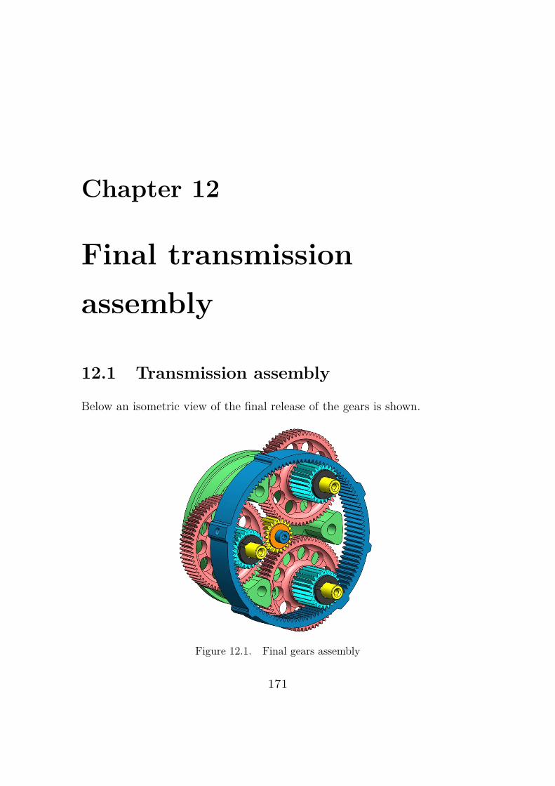
Chapter 12
Final transmissionassembly
12.1 Transmission assembly
Below an isometric view of the final release of the gears is shown.
Figure 12.1. Final gears assembly
171

12 – Final transmission assembly
Also, below the full final transmission assembly is shown. also the wheelbearings and the hub are shown.
Figure 12.2. Final gearbox assembly
Figure 12.3. Final gearbox assembly
172

12.2 – Transmission integration
12.2 Transmission integration
Below a view of the transmission and the motor assembled is shown. Alsothe motor mounting flange can be seen.
Figure 12.4. Final gearbox assembly
Finally the integration of the gearbox into the wheel assembly is shown.It is then clear that the package in this area is critical and how reducing thevolume of the transmission is beneficial for the freedom in suspension design.
Figure 12.5. SC18integrale transmission assembled
173

174

Part II
Second part
175


Chapter 13
Results obtained
13.1 Weight reduction
Below a table with the weight reduction per each components with respectto SCdiciassette upright is shown.
Component N Weight 2017 [kg] Weight 2018 [kg]Sun gear assembly 1 0.141 0.024
Planet gears assembly 3 0.192 0.138Ring gear assembly 1 0.412 0.157Planetary carrier 1 0.278 0.141
Hub 1 0.771 0.612Wheel bearings 2 0.28 0.15
Wheel bearings locknut 1 0.053 -Screws 3 0.02 0.011Oil 1 0.18 0.09Total - 2.871 1.693
Table 13.1. Weight comparison
Total weight reduction: - 1.178 kg, - 41 %, overtaking the 30 % target atthe beginning of the project. It must be noticed that the reduction in volumeand in weight of the transmission impacts largely also on the weight of the
177

13 – Results obtained
upright and of the motor flange, thus increasing even more the advantagescoming from its volume reduction.
Note:
• The planet gears assembly includes the needle roller bearings and thepin shaft (if any)
• The SCdiciassette sun gear assembly includes its bearings and the bear-ings preload locknut
• The ring gear assembly includes its retention system
Figure 13.1. Comparison between the SCdiciassette ring gear (left) andthe SC18integrale one (right)
178

13.2 – Volume reduction
Figure 13.2. Comparison between the SCdiciassette planet gears assembly(left) and the SC18integrale one (right)
13.2 Volume reduction
Below a comparison between the SCdiciassette and SC18integrale transmis-sion main dimensions is shown.
Dimension Size 2017 [mm] Size 2018 [mm]Overall length 89.5 72
Bearings outer diameter 125 100Planet gears maximum diameter 133 120
Table 13.2. Main dimensions comparison
The "Planet gear maximum diameter" is in absolute terms the maximumdiameter of the gearbox. It impacts into the upright because the higher thisdiameter is with respect to the bearings diameter, the deeper the groove intothe upright to allow the planetary gear movement should be. Its impact onthe overall volume is however limited due to the fact that the groove axiallength is just slightly higher than the second stage planetary gear facewidth.
179

13 – Results obtained
The main contributors to the overall size of the transmission are indeedthe bearings outer diameter and the overall length. For this reasons thosetwo parameters are used to compare the volume reduction: both the diameterand the overall length have been reduced by 20 %, overtaking the 15 % target.
13.3 Assembly process
Figure 13.3. Transmission parts before assembly
Due to tight tolerances imposed and good material properties required, allthe components have been checked before assembly. The teeth have beenverified according to their Wildhaber dimension specified in the technicaldrawing and the phase between the teeth in the planetary gear have beenmeasured with a coordinate measurement machine. The surface hardnessof all the components has been also checked, in particular the one of thering gear that was the most critical components in terms of safety factors
180

13.3 – Assembly process
according to the calculations.
Figure 13.4. Hardness check on the ring gear
The grooves machined into the upright to house the ring gear revealedto be difficult to be realized during manufacturing due to low fillet radiusand large tool overhang. This forced the manufacturer to test the ring gearfit while machining a progressively removing material from the upright untilthe required fit was guaranteed, resulting in having to fit each ring gear inthe proper upright (both those two components were punched with the sameletter in order to avoid assembly errors).
181

13 – Results obtained
Figure 13.5. Ring gear mounted into the upright
With a coordinate measurement machine the measures needed to deter-mine the thickness of the wheel bearings preload ring (as shown in Section6.3) are taken.
The whole transmission assembly process takes 2 hours per each groupfor the first it is performed, for this reason it was possible to speed up theassembly of the car. Performing a gear maintenance without removing thebearings is really quick, it lasts less than an hour, this assembly times arereally a progress with respect to the previous year’s one, SCdiciassette trans-mission assembly for the first time took around four/five hours.
The transmission assembled is shown below.
182

13.4 – Formula Student Spain failure
Figure 13.6. SC18itegrale transmission assembled
13.4 Formula Student Spain failure
During the practice session of Formula Student Spain a failure is reportedbecause the retaining screw of one of the sun gears got loose and caused thesun gear to move from its design position.
This failure was repaired quickly due to the easiness of assembly of thegearbox and the car was ready to be back on track in less than an hour.Anyway, this failure raise concern regarding the necessity of a preveilingmechanism for the retaining screw of the sun gear.
Below some pictures of the failure are shown.
183

13 – Results obtained
Figure 13.7. Formula Student Spain Failure
13.5 Gearbox life
Through log files post-processing the overall vehicle and so the gearbox lifecould be exactly determined.
Event Working time [h] Distance [km]June 2018 pre-season testing 1.9 62July 2018 mid-season testing 3.1 121
August 2018 mid-season testing 3.8 150October 2018 post-season testing 0.4 21November 2018 post-season testing 1.4 63
April 2019 post-season testing 1.7 73May 2019 post-season testing 5.4 212June 2019 post-season testing 6.0 257
FSAE Italy 0.9 29Formula Student Spain 1.1 36
Total 25.7 1024
Table 13.3. SC18integrale recorded running time and distances
184

13.6 – Motor working points
The life of the vehicle and so of the transmission resulted to be lower withrespect to what was predicted at the beginning of the project. This is dueto the fact that the predicted life was an estimation and most of all thatimportant delays is the production conditioned the pre-season tests, forcingthem to be far less with respect to what was predicted.
Figure 13.8. SC18itegrale gears inspection after 25 h
13.6 Motor working points
In this section the motor working points logged during a track test are su-perimposed to the efficiency map, both for a rear and a front motor and bothin traction and in regenerative braking.
185

13 – Results obtained
Figure 13.9. Rear motor working points in traction
Figure 13.10. Rear motor working points in regenerative braking
As anticipated in Section 10.3 not all the points of the efficiency map are
186

13.6 – Motor working points
reachable due to the power limit of the motor (20 kW). The power limit curveis clearly visible in Figure 13.9.
Figure 13.11. Front motor working points in traction
Figure 13.12. Front motor working points in regenerative braking
187

13 – Results obtained
It can be also noticed that the regenerative braking is the regenerativebraking torque is demanded mostly to the front motors rather than the rearones.
Finally it can be noticed that during acceleration the front wheels aretraction-limited rather than power-limited.
188

Chapter 14
Conclusions and futureperspectives
14.1 Conclusions
Both the weight reduction and the volume reduction targets were overtaken,bringing to a really satisfactory result.
As seen, also the assembly time was considerably reduced, permitting torecover part of the delay coming from manufacturing and saving fundamentaltime for testing. The easiness of assembly and rebuild was also seen duringthe accident in Formula Student Spain, where in less than an hour the carwas ready to be back on the race track.
Unfortunately due to production delays the life of the car resulted to besignificantly lower than expected so correctness of the gear life calculationwas not tested properly. However, apart from the little accident during For-mula Student Spain, the gearbox operated in a satisfactory way for the wholeseason and also post-season testing, without the need of further maintenance.
189

14 – Conclusions and future perspectives
In general, all the vehicle’s project was really successful both from a designand performances point of view. Important improvements in terms of overallvehicle mass, battery pack performance and reliability and controls systemshave been implemented during the season.
Unfortunately the lack of time in pre-season tests prevented SC18integraleto express its full potential during races. An important third place duringFormula SAE Italy was achieved by the Team.
14.2 Future perspectives
The present work showed that even reducing significantly the normal mod-ule and the size of the gears, large safety factors can be achieved and a goodreliability is obtained. Ideally the size of those gears can be reduced evenmore, clearly the manufacturing aspect must be kept in mind when choosingan extremely small normal module.
Also, further investigation on the fatigue behaviour is worthy to be carriedin order to design properly an aluminum hub and reducing even more theweight of the component.
In conclusion, it will be really interesting to be able to effectively testbench the transmission, in order to validate properly both the expected lifeand the efficiency of the gear train.
190

Appendix A
AMK motor datasheet
191

A – AMK motor datasheet
Figure A.1. AMK motor datasheet [20]192

A – AMK motor datasheet
Figure A.2. AMK motor datasheet [20]193

194

Appendix B
Double stage epicycloidalgearboxes layouts
195

B – Double stage epicycloidal gearboxes layouts
Figure B.1. ANSI/AGMA 6123-B06 [1]196

Appendix C
Wheel locknut tighteningtorque computation
As discussed in Section 8.2 it is decided to size the wheel locknut tighteningtorque in order to be able to transmit entirely by friction the tangential loadsduring traction. The maximum torque available at the wheel during traction(Tmax) is given by:
Tmax = Tm ∗ τ = 21 ∗ 14.8 = 311Nm (C.1)
Where:
• Tm is the maximum torque supplied by the motor
• τ is the transmission ratio
The axial force (Fa) required to transmit all the loads by friction is equalto:
Fa = Tmaxf ∗Rf
(C.2)
Where:
197

C – Wheel locknut tightening torque computation
• Rf is the friction radius
• SF is the required safety factor
• f is the friction coefficient
Figure C.1. Section view of the clamped parts between the hub andthe wheel locknut
As shown in Figure C.1 various components are clamped between thelocknut and the hub flange (rim, wheel spacer and brake disc carrier). Inthis computation the effect on the load distribution between the clampedparts have been neglected. Also, it was not possible to find the magnesium-aluminum and aluminum-titanium friction coefficients in literature. For thementioned reason friction coefficient f is set to 0.4, arbitrarily low in orderto stay on the safe side for this analysis.
The required safety factor is set to 1.5 due to the fact that the locknut istightened every time with a certified torque wrench.
198

C – Wheel locknut tightening torque computation
The friction radius Rf is the average radius of the surface involved inthe shear forces transmission by friction, assuming the axial force evenlydistributed on the surface, i.e. constant pressure exerted by the axial forcedue to tightening. Defining as Ri the inner radius of the surface At involvedin the threaded coupling (the one where the shear forces are transmitted byfriction) and as Ro the outer radius that the surface At would have if it wasring-shaped, the following expression can be written:
At = π(R2f −R2
i ) = 3436mm2 (C.3)
The outer radius Ro can be then computed.
Rf =ó
(Atπ
+R2i ) = 49.6mm (C.4)
Figure C.2. Measures on the wheel hub
At and Ri are measured from the hub CAD model, as shown in Figure ??.At this stage the average friction radius Rf can be computed as:
199

C – Wheel locknut tightening torque computation
Rf = Ri +Ro2 = 43.3mm (C.5)
The axial load need to ensure that all the shear loads are transmitted byfriction can be now calculated, resulting to be:
Fa = 26909N (C.6)
The thread is of the metric type, M72x1.5, below its characteristic dimen-sions are reported.
• d = 72mm (nominal diameter)
• dm = 71.026mm (mean diameter)
• p = 1.5mm (pitch)
• β = 30ř (thread angle)
Knowing the characteristics of the thread, the tightening torque needed toguarantee the axial force Fa previously determined can be finally computed[16].
MT = Fa2 (p
π+ dm ∗ tanφ
cosβ+ dt ∗ tanφs) = 242.7Nm Ä 250Nm (C.7)
Where:
• tanφ = tanφs = 0.4
• dt = 1.3 ∗ d (average locknut diameter)
200

Appendix D
Gear train technicaldrawings
201

D – Gear train technical drawings
Figure D.1. Sun gear drawing [28]202

D – Gear train technical drawings
Figure D.2. First stage planet gear drawing [28]203

D – Gear train technical drawings
Figure D.3. Second stage planet gear drawing [28]204

D – Gear train technical drawings
Figure D.4. Planet gears assembly drawing [28]205
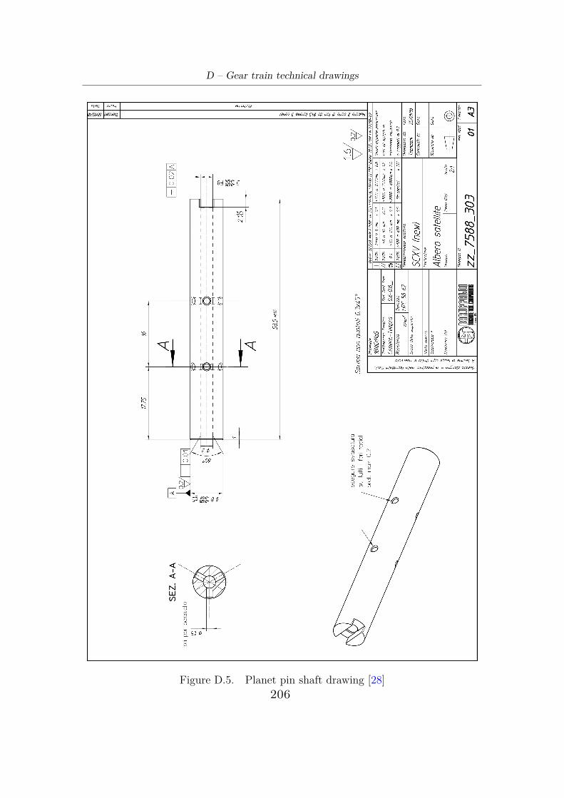
D – Gear train technical drawings
Figure D.5. Planet pin shaft drawing [28]206

D – Gear train technical drawings
Figure D.6. Planet gears spacer drawing207

D – Gear train technical drawings
Figure D.7. Ring gear drawing208

D – Gear train technical drawings
Figure D.8. Ring gear drawing209

D – Gear train technical drawings
Figure D.9. Ring gear screws drawing210

Appendix E
Planetary carrierassembly technicaldrawings
211

E – Planetary carrier assembly technical drawings
Figure E.1. Hub drawing212

E – Planetary carrier assembly technical drawings
Figure E.2. Planetary carrier drawing213

E – Planetary carrier assembly technical drawings
Figure E.3. Planetary carrier assembly drawing214

E – Planetary carrier assembly technical drawings
Figure E.4. H-shaped bushing drawing215

E – Planetary carrier assembly technical drawings
Figure E.5. Wheel locknut drawing216

Appendix F
Lubricant datasheet
217

F – Lubricant datasheet
Figure F.1. Motul Gear 300 75w90 dataheet [27]218

Bibliography
[1] ANSI/AGMA 6123-B06, Design Manual for Enclosed Epicyclic GearDrives, American Gear Manufacturers Association, 2006.
[2] ISO 6336:2006, Calculation of load capacity of spur and helical gears,International Organization for Standardization, 2006.
[3] Stephen P. Radzevich, Dudley’s Handbook of Practical Gear Design andManufacture, CRC Press, 2016.
[4] D.W. Dudley, J. Sprengers, D. Schröder, H. Yamashina Manuale delMotoriduttore - Bonfiglioli, Springer, 1997.
[5] A. Dobler, M. Hergessel, T. Tobie, K. Stahl, Increased Tooth BendingStrength and Pitting Load Capacity of Fine Module Gears, Geartechnol-ogy (September/October 2016), 48-53, 2016.
[6] B. Jeong, M. Kato, K. Inoue, N. Takatsu, The Bending Strength ofCarburized Fine Module Gear Teeth, JSME International Journal (Vol.35, No. 1, 1992), 136-141, 1992.
[7] Heinz Linke, Cylindrical Gears: Calculation, Materials, Manufacturing,
219

Bibliography
Carl Hanser Verlag, 2010.
[8] Massimiliano Turci, Errore di trasmissione e modifiche di ingranaggi,2019.
[9] KISSsoft AG, Help manual.
[10] KISSsoft AG, KISSsys 03/2014 – Tutorial 2: One Stage PlanetaryGearbox, 2014.
[11] SKF, Super-precision bearings catalogue, 2015.
[12] SKF, Needle roller bearings catalogue, 2015.
[13] SKF, Industrial shaft seals catalogue, 2013.
[14] Fabrizio Mandrile, Squadra Corse calculations report, 2018.
[15] Angst+Pfister, Basic catalogue, 2007.
[16] Giovanni Belingardi, Slides from the "Machine Design" course, Politec-nico di Torino, 2016.
[17] Carlo Emilio Baret, Enrico Galvagno, Slides from the "PowertrainComponents Design: Transmission" course, Politecnico di Torino, 2018.
[18] ISO Technical Report 1417, Gears - Thermal capacity, InternationalOrganization for Standardization, 2001.
220

Bibliography
[19] Squadra Corse PoliTO, Gear train design presentation, 2015.
[20] AMK, DD5-14-10 POW Motor-Datenblatt, 2015.
[21] Edoardo Zo’, Design of a Planetary Gear Train for a FSAE Full ElectricVehicle, 2019.
[22] Mattia Viteritti, Drivetrain optimization of a Formula SAE racingprototype, 2017.
[23] Luis Daniel Medina Querecuto, Design and Validation of the UnsprungMasses of a Formula SAE vehicle, 2020.
[24] R. Boyer, G. Welsch, E. W. Collings, Materials Properties Handbook:Titanium Alloys, ASM International, Materials Park, OH, 1994.
[25] Kaiser Aluminum, Aluminum alloy 7068 brochure.
[26] Kaiser Aluminum, Aluminum alloy 7075 technical data.
[27] Motul, Gear 300 75W90 technical datasheet.
[28] Thomas Tronconi, Tavole riduttore per Squadra Corse PoliTo, BaruffaldiS.p.A., 2018
221