ENHANCEMENT OF ENERGY EFFICIENCY, VEHICLE SAFETY AND RIDE COMFORT FOR ALL-WHEEL DRIVE FULL ELECTRIC...
18
EB2014-BA-007 ENHANCEMENT OF ENERGY EFFICIENCY, VEHICLE SAFETY AND RIDE COMFORT FOR ALL-WHEEL DRIVE FULL ELECTRIC VEHICLES 1 Savitski, Dzmitry*, 1 Augsburg, Klaus, 1 Ivanov, Valentin 1 Ilmenau University of Technology, Germany KEYWORDS – brake force distribution, brake blending, optimization, regenerative braking, electric vehicle ABSTRACT The optimal brake control in the case of a full electric vehicle must not only guarantee high brake performance but also aim at maximum possible level of energy regenerated during the manoeuvre. Targeting integrated electric vehicle control, the driving comfort should be also considered as a component requiring optimization. These factors have motivated the presented study and allowed to formulate the main objective: Development of optimal brake control strategy based on three criteria – brake performance, energy efficiency, and ride comfort. The research is subjected to a full electric passenger vehicle equipped with four in-wheel motors and an electro-hydraulic brake system. On the first stage of the research, the optimization procedure is proposed for the brake torque distribution. Three domains are chosen for the shaping of the corresponding optimization cost function: the brake performance is being estimated by deceleration tracking during the manoeuvre; the energy consumption is quantified through regenerative energy and tyre dissipation energy; the indicator for the ride comfort (in the case of straight-line braking) is the pitch angle. The verification of the developed brake control functions is carried out using the vehicle simulator in IPG CarMaker and hardware-in-the-loop platform with installed electro-hydraulic brake system. The straight-line braking manoeuvre has been investigated as the case study. The proposed technique allowed to reach an optimal brake force distribution with high level of brake energy recuperation and simultaneous keeping of required safety level. The pitch oscillations caused by the vehicle behaviour at emergency braking have been also reduced as compared with the brake manoeuvre without brake distribution / blending control. The experiments were done on the basis of model- and hardware-in-the-loop simulations. The characteristics of electric motors are deduced from experimental data. The real hardware components of the brake system are used including the hydraulic control unit. The controller is emulated in real-time mode using dSPACE tools. The results of the presented study have showed that an optimal brake control in the case of the electric vehicle allows to achieve a multilateral effect in reduction of the brake distance, increase of brake energy regeneration and improvement of the ride comfort at braking.
-
Upload
tu-ilmenau -
Category
Documents
-
view
4 -
download
0
Transcript of ENHANCEMENT OF ENERGY EFFICIENCY, VEHICLE SAFETY AND RIDE COMFORT FOR ALL-WHEEL DRIVE FULL ELECTRIC...

EB2014-BA-007
ENHANCEMENT OF ENERGY EFFICIENCY, VEHICLE SAFETY AND
RIDE COMFORT FOR ALL-WHEEL DRIVE FULL ELECTRIC
VEHICLES 1Savitski, Dzmitry*,
1Augsburg, Klaus,
1Ivanov, Valentin
1Ilmenau University of Technology, Germany
KEYWORDS – brake force distribution, brake blending, optimization, regenerative braking,
electric vehicle
ABSTRACT
The optimal brake control in the case of a full electric vehicle must not only guarantee high
brake performance but also aim at maximum possible level of energy regenerated during the
manoeuvre. Targeting integrated electric vehicle control, the driving comfort should be also
considered as a component requiring optimization. These factors have motivated the
presented study and allowed to formulate the main objective: Development of optimal brake
control strategy based on three criteria – brake performance, energy efficiency, and ride
comfort.
The research is subjected to a full electric passenger vehicle equipped with four in-wheel
motors and an electro-hydraulic brake system. On the first stage of the research, the
optimization procedure is proposed for the brake torque distribution. Three domains are
chosen for the shaping of the corresponding optimization cost function: the brake
performance is being estimated by deceleration tracking during the manoeuvre; the energy
consumption is quantified through regenerative energy and tyre dissipation energy; the
indicator for the ride comfort (in the case of straight-line braking) is the pitch angle. The
verification of the developed brake control functions is carried out using the vehicle simulator
in IPG CarMaker and hardware-in-the-loop platform with installed electro-hydraulic brake
system.
The straight-line braking manoeuvre has been investigated as the case study. The proposed
technique allowed to reach an optimal brake force distribution with high level of brake energy
recuperation and simultaneous keeping of required safety level. The pitch oscillations caused
by the vehicle behaviour at emergency braking have been also reduced as compared with the
brake manoeuvre without brake distribution / blending control. The experiments were done on
the basis of model- and hardware-in-the-loop simulations. The characteristics of electric
motors are deduced from experimental data. The real hardware components of the brake
system are used including the hydraulic control unit. The controller is emulated in real-time
mode using dSPACE tools.
The results of the presented study have showed that an optimal brake control in the case of the
electric vehicle allows to achieve a multilateral effect in reduction of the brake distance,
increase of brake energy regeneration and improvement of the ride comfort at braking.

TECHNICAL PAPER
INTRODUCTION
New variants of powertrain and chassis architecture are continuously addressed in recent
studies in electric vehicle engineering. In particular, many trends in powertrain development
aim to reduce the complexity of transmission elements and size of electric motors with
simultaneous improvement of their performance. In this context, one of the promising
solutions is an on-board architecture with individually controlled motors on each wheel. Such
kind of architecture reduces the power losses due to absence of the central or axle differential,
improves compactness and proposes more flexible wheel torque control. Nevertheless the
half-shafts and reduction gears in this type of powertrain still exist. They can be eliminated
using the compact in-wheel motors transferring the power directly to the wheel without any
transmission elements. In general such powertrain composition provides much better response
time, extends the operational frequency and reduces power losses.
Modern electric vehicles are also using new brake architecture and, first of all, brake-by-wire
concepts represented by electro-mechanical (EMB) and electro-hydraulic (EHB) brake
systems. Nowadays EHB systems with hydraulically decoupled brake pedal and callipers are
gaining more and more acceptance due to benefits in fast response time and individual control
on each wheel in comparison to the conventional brake systems. In the case of electric fail the
EHB system maintains the functionality of the hydraulic brake system, but without boost
control.
Thus, a combined use of electric powertrain with the individually controlled motors and the
decoupled brake system can benefit energy efficiency, brake performance, fun-to-drive,
vehicle stability and handling, emissions reduction and other operational characteristics of the
vehicle. In the same time, several other characteristics, which can be also improved by using
of combined actuators of an electric vehicle, are still rarely investigated. In particular, it
concerns the ride comfort, which can be also potentially improved using the brake control.
Several preliminary solutions in this area are known from research literature. Fujimoto and
Sato propose in (1) and (2) the control of the pitch angle both through advancement of
conventional wheel slip control functions and electric motors. However, the proposed method
is applicable only at the low vehicle velocities. Morita and Matsukawa introduce the method
for pitch reduction by increasing of the rear brake force (3). This approach represents only a
particular case of brake force distribution and requires specific suspension adjustments.
In the proposed research the particular task of pitch angle reduction and improvement of ride
comfort is related to the optimal brake force distribution. The potential of such optimization is
mostly investigated in scope of energy efficiency and vehicle safety (4-5). Authors propose to
consider the correlation between all three vehicle characteristics and find optimal solution for
the different driving modes. This solution can be additionally used with brake blending
algorithms to gain their efficiency in any driving mode.
Since the most of optimization procedures are carried out without considering external
disturbances, the strategy of their compensation is proposed basing on approach proposed in
(6). This control strategy demonstrates its efficiency, when the long-term processes such as
wear of tires or brake pads influence on the braking efficiency.
Special attention in this paper is addressed to the testing procedure of control algorithms for
electric vehicles. Except of the spread used hardware-in-the-loop (10) technique the test rig
in-the-loop (TRIL) approach proposed by Augsburg et. al (7) realized particularly for the

EHB system and disc brakes. This testing method directly uses the information from other test
benches shorting the step between test bench experiments and the road tests.
Scanty exploration of integrated brake performance and ride control for electric vehicles has
motivated the presented study and allowed to formulate next objectives:
Development of optimization procedures allowing tuning of the base brake control
functions by criteria of vehicle safety, energy efficiency and ride comfort;
Realization of the developed optimization tools for specific electric vehicle
configuration with individually controlled in-wheel motors and decoupled electro-
hydraulic brake system;
Improvement of vehicle safety the developed brake controller through embedding of
correction mechanisms compensating external disturbances.
Experimental validation of the brake controller using hardware-in-the-loop (HIL)
platform and advanced with use dynamometric test bench.
The results of works performed in accordance with the proposed objectives are being
presented in next chapters of the paper.
MODEL OF ELECTRIC VEHICLE AND SUBSYSTEMS
The vehicle under investigation is the sport-utility vehicle (SUV) with overall mass of 2045
kg. The vehicle is equipped with an electro-hydraulic brake system and powertrain with
individual in-wheel electric motors, Figure 1.
Figure 1: Electric vehicle configuration
For the steady-state operation of electric motors the torque maps represented Figure 2 are
used. The transient operation of motors is described through the first-order transfer function
(13):
, 0.002
,
1
0.0022 1
em i s
ss
em i
Te
T s
. (1)

The suspension system is represented by (i) springs with constant stiffness of 26700 and
23000 N/m for front and rear axle respectively, (ii) stabilizers with stiffness of 8251.4 and
6833.5 N/m for front and rear axle correspondingly, and (iii) shock absorbers with
characteristics shown in Figure 3.
Figure 2: Torque-speed and efficiency characteristics of the in-wheel electric motor
Figure 3: Shock absorber characteristics
For the simulation and optimization procedures the behaviour of the brake system is
represented by the validated first-order transfer function:
0.0251
0.02 1
actsi
ref
i
pe
p s
. (2)
The vehicle is equipped with tyres 235/60 R18. Tyre parameters in the brake controller are
deduced with the use of Pacejka model.
CRITERIA FOR INTEGRATED ASSESSMENT OF VEHICLE DYNAMICS
A set of the assessment criteria require formulation to evaluate ride comfort, vehicle safety
and energy efficiency. These criteria can be further used for the purposes of optimization
related to the longitudinal brake events at any appropriate part of the vehicle controller.

The vehicle safety is characterized in the proposed optimization procedures through the error
between actual and reference vehicle deceleration. This criterion is covering in particular
some special cases as driving in platoon: underestimated braking distance can provoke an
accident. It is proposed to use integral of time-multiplied absolute value of deceleration
tracking error:
0
T
ITAE act ref
x x xa a a dt . (3)
The reference value of the vehicle deceleration is calculated from “brake pedal travel-
deceleration” characteristic implemented in the base-brake control algorithm and described
further.
Energy characteristics are estimated with two criteria. The most important and valuable of
them is the recuperated energy, which can be harvested using operation of electric motors in
the generator mode. This energy can be expressed through the electric motor power:
4
,
1 0
T
brake
em em i
i
E P dt
. (4)
Another parameter related to energy efficiency in the case of the longitudinal motion of the
vehicle is the tyre energy dissipation, which can be derived from the longitudinal tyre forces
and wheel slip speeds:
4
, ,
1 0
T
slip
tyre xw i xw i
i
E F V dt
. (5)
For the cases of vehicle braking on the flat road, ride comfort can be characterized by the
dynamics of the pitch angle both in steady-state and transient conditions. For this purpose the
integral value of the pitch angle error is proposed:
0
T
ITAE act ref dt , (6)
As soon as any vertical oscillations are negatively influence ride comfort, the reference value
of the pitch angle θref
(an ideal case) can be set to zero.
OVERALL CONTROL STRUCTURE
General Description
The brake controller of electric motors and electro-hydraulic brake subsystem consist of next
main functional parts,
Figure 4: (i) state and parameter estimation; (ii) base-brake controller; (iii) disturbances
compensator; (iv) brake force distribution; (v) brake blending.

Figure 4: Controller structure
The input from the driver is the brake pedal displacement acquired by corresponding sensor.
This signal is addressed to the base-brake controller calculating the total torque demand for
required level of deceleration. The demanded torque is corrected in accordance to the external
disturbances and addressed to the brake torque distribution block, where the demand is
separated to the front and rear axles according to the predefined algorithm. The brake
blending block allocates these torques individually to each wheel. The final torques are
realized by the corresponding vehicle subsystem: friction brake system or electric motors. The
state observer supplies the functional block with data which can be obtained only by indirect
methods. This state observer has a multiple-model structure with combined several
observation methods working in parallel. On the output there are tire forces, vehicle actual
mass, road grade, rolling resistance and air drag forces. The detailed description of the state
observer is skipped in the framework of the proposed research.
Base-brake Controller
The base-brake controller generates total torque demand for requested vehicle deceleration
and works in an open-loop mode. The reference deceleration value is calculated from the
relation between the brake pedal displacement and the vehicle deceleration,
Figure 5.
Figure 5: Reference deceleration level in accordance to brake pedal displacement
The total torque demand produced by base-brake controller can be formulated as follows:
ref
demand a x wT m a r , (7)

where m is the vehicle mass, rw is the wheel radius.
The torque demand from Eq. (7) does not consider external disturbances occurring during the
vehicle motion. A particular case with disturbances and their compensation will be discussed
in next chapters.
Brake Blending
The brake blending algorithm has individual wheel torque demands as the inputs and
separates them between the electric motors and the hydraulic brake system. The algorithm
takes into consideration the motor torque constraints determined by the battery limitation and
the motor operation mode. The presented brake blending strategy aims to the maximum
energy recuperation and maximum use of electric motors functionality on the high-frequent
operation modes. In general the brake blending algorithm logic is based on the set of rules and
limitations:
The torque of electric motor is used at maximum possible level in relation to the
hydraulic brake system to ensure the energy-efficient braking;
On low vehicle velocities only friction brake system is used due to the low efficiency
of electric motors in energy recuperation;
Torque demands of higher frequencies are realized through electric motors.
The calculated torque is sent to the low-level actuator controllers, which are responsible for
the realization of appropriate torque requests.
Brake Torque Distribution
The brake torque distribution block is responsible for the separation of the total torque
between the front and rear axle in accordance to the predefined rules. In contrast to the widely
used distribution strategies focused only on the vehicle safety, the influence of the brake force
distribution on some particular characteristics should be evaluated in the case of the electric
vehicle. Within this context, the presented work has studied the influence of the brake
distribution strategy on the assessment criteria from Eqs. (3)-(6) to estimate the feasibility of
the brake force distribution optimization in relation to integrated criteria of safety, energy
efficiency and ride comfort.
To show the potential benefits from optimization of brake force distribution, a set of typical
distributions has been analysed: (i) constant and (ii) bilinear distribution. The represented
distributions are investigated in several variations.
The brake force distributions operate with the ratio between the rear brake force and total
brake force:
br br
rear totalF F . (8)
This ratio can be both constant and variable in accordance to the current deceleration level Zi.
Constant Brake Force Distribution
The brake force distribution from Figure 6 is represented by the constant -ratio, i.e. the
front and rear brake forces have a linear relation. The -ratio is varied in range from 0.03,

which is close to the ECE limitations line, and up to 0.5. Some of corresponding distributions
are shown in Figure 6 as dashed lines.
Figure 6: Variations of constant brake force distribution
The distribution ratio influence on the pitch transient characteristics can be seen on Figure 7:
Pitch angle responseFigure 7, where the difference in the oscillations amplitude can reach up to 0.6
degree depending on the -value. It can be concluded that the increase of the brake force on
the rear axle can lead to the reduction of pitch angle. This effect is also discussed in studies of
other authors (3). Figure 8 shows a tendency of deceleration error decrease up to =0.18 and
then the ITAE-value raises again. Hence, with this brake distribution variant, the
improvement of vehicle safety criteria does not lead to a noticeably better ride comfort.
Figure 7: Pitch angle response
Figure 8: Deceleration ITAE
It is important to mention the correlation between the recuperated energy and tyre energy
dissipation in relation to the brake force distribution ratio, Figures 9 and 10. Minimum levels
of the tyre energy dissipation and the recuperated energy are observed for the same range of
the -ratio. On the other hand, the highest potential for the brake energy regeneration takes
place within the range the -ratio, where the tyre energy dissipation is increased. Hence, the
constant brake force distribution is characterized by a conflict between both criteria of energy
efficiency.

Figure 9: Recuperated energy
Figure 10: Tyre energy dissipation
Ideal (Bilinear) Brake Force Distribution
An ideal distribution in particular case is represented by a set of bilinear distributions. It
consists of two lines connected in the switch point. Figure 11 shows how they are being
changed in respect to the shifting of switch deceleration from 0.05 to 0.95 g with the step of
0.05 g. It can be seen, that the pitch angle represented in Figure 12 has actually no strong
dependence on switch point position. It means that the ideal brake force distribution has less
potential to an essential improvement of the ride comfort as compared with the case of the
constant distribution.
Figure 11: Variations of bilinear brake force distribution
Figure 12: Pitch angle response
Figure 13: Deceleration ITAE

The conflict between criteria of the tyre energy dissipation and energy regeneration, described
in previous section of the paper, takes place also at the ideal brake force distribution, Figures
14 and 15. However, it can be noted that more important criterion - recuperated energy - has
a good correlation with the deceleration error, Figures 13. It can guarantee maintenance of
high safety level for the energy efficient algorithms.
Figure 14: Recuperated energy
Figure 15: Tyre energy dissipation
As it can be seen from the aforementioned analysis, simultaneous improvement of ride
comfort, vehicle safety and energy efficiency is potentially feasible and can be realized
through the procedures of brake forces optimization, which are described in next chapter.
BRAKE FORCE DISTRIBUTION OPTIMIZATION
Previous chapter has indicated certain conflict between ride comfort, vehicle safety and
energy efficiency in the case of conventional variants of brake force distributions. To resolve
this task, optimization of the brake force distribution should be carried out. Since the
optimization procedure operate with different vehicle characteristics, a corresponding cost-
function has to be composed. For this purpose the criteria from Eqs. (3)-(6) can be used as
follows:
1 2 3 4
max( ) max maxmax
ITAE ITAE
x em tire
ITAE ITAEx em tire
f a f f E f EJ w w w w
a E E
. (9)
Weight coefficients wi are represented by three cases to cover three different driving modes
aimed to (i) pitch angle reduction, (ii) normal mode with approximately equivalent weights
for each parameter, and (iii) maximum energy recuperation respectively. The parameters to be
optimized are ratios Φi for the predefined decelerations Zi. In the proposed solution eight
points from 0.1 to 0.8 g with step of 0.1 g are used. Constraints imposed on the Φ-ratio are
represented by the two typical curves: ECE regulation curve and ideal distribution curve
(prevention of earlier lock of the rear axle).
The thermal constrains of brake discs and electric motors are neglected due to the complexity
of its estimation in the investigated wheel hub architecture.
The approach selected to solve the optimization procedure is based on the interior-point method. The output
vector consists of the eight Φi distribution ratios depicted as the red dots in

Figure 16.
Figure 16: Example of optimization procedure with found optimal points
The efficiency evaluation of the optimized distributions is done by means of the hardware-in-
the-loop technique and using the real electro-hydraulic brake system TRW SCB (8) and will
be further introduced.
It should be mentioned that the presented study has used a more complex vehicle model for
the offline optimization procedure in comparison to known approaches. In particular, the
computation of brake torques in accordance with optimized -ratio is advanced with the
correction mechanisms compensating the influence of external disturbances on the brake
dynamics. This aspect is rarely presented in the brake controller variants known from the
research literature. The basic information of the proposed compensators is presented in next
chapter.
DISTURBANCES COMPENSATOR
In the previous chapters the tracking of the longitudinal deceleration as the assessment
criterion of vehicle safety was investigated in scope of the absence of external disturbances. In
the reality the deceleration tracking can be worsen by resistance forces and degradation of
tyre and brake friction characteristics. Such decrease in tracking precision can be occurred in
the case of brake lining friction coefficient fluctuations that have been investigated within the
framework of the presented research. To improve tracking of the deceleration minimizing the
error in Eq. (3) and to enhance vehicle safety, an original disturbance compensation algorithm
is proposed. This compensation algorithm is based on the evaluation of correction factor used
to produce the compensation torque demand.
The longitudinal vehicle motion and rotational wheel dynamics neglecting the losses and
resistance of propulsion system can be written as follows (5):
4
1i
act act
a x x aero roll grade
i
m a F F F F
, (10)
w w w x wI T F r , (11)

Assuming that the component i iw wI is insignificant in comparison with the wheel torque
iwT
the Eq. (11) can be formulated as:
4
1
i
i
act
wact act
a x aero roll grade x aero roll grade
i w
Tm a F F F F F F F
r
. (12)
The actual torque i
act
wT can be distorted in comparison to the demand i
dem
wT due to the several
reasons such as tyre pressure inflection/deflection, tyre wear, brakes overheating, etc. To
compensate this difference, the correction factor fcor is proposed:
ref act
a x cor x aero roll gradem a f F F F F . (13)
The demanded deceleration can be expressed through the demanded brake force:
ref dem
a x x aero roll gradem a F F F F . (14)
Assuming precise estimation of the aerodynamic drag force, rolling resistance and road grade,
the following equation can be proposed:
ref ref act dem
a x cor a x x x compm a f m a F F F . (15)
Therefore the compensation torque compT required to minimize error between actual and
reference deceleration in relation to the correction factor can be expressed as follows:
1cor demand compf T T . (16)
To estimate the correction factor, the recursive least squares method is used with the
following formulation:
1ˆ ; ; act act
a x x aero roll grade
cor
y m a F F F Ff
. (17)
The correction factor can be applied for the case of lining friction coefficient deviation
between the value stored in the controller and the real value. Lining friction coefficient is used
in the calculation procedure for the conversion of the brake torque demand to the pressure
demand, which should be sent to the EHB system:
2
friction
actuali out
wc eff L
TP P
A r , (18)
where L is lining friction coefficient; friction
totalT is the friction brake system torque demand.
Due to the open-loop pressure control, the difference in the friction coefficient value stored in
the controller and the real value can cause the brake torque distortion. To avoid such a
situation, the mentioned compensation procedure is required. Its implementation will be also
presented in next chapter for the case of fading effect.
EXPERIMENTAL PLATFORM AND RESULTS
Experimental platform description
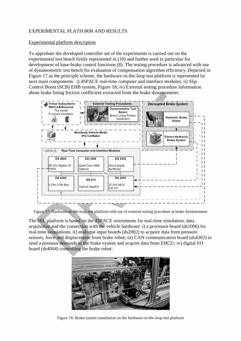
To approbate the developed controller set of the experiments is carried out on the
experimental test bench firstly represented in (10) and further used in particular for
development of base-brake control functions (8). The testing procedure is advanced with use
of dynamometric test bench for evaluation of compensation algorithm efficiency. Depicted in
Figure 17 as the principle scheme, the hardware-in-the-loop test platform is represented by
next main components: i) dSPACE real-time computer and interface modules; ii) Slip
Control Boost (SCB) EHB system, Figure 18; iv) External testing procedure information
about brake lining friction coefficient extracted from the brake dynamometer.
Figure 17: Hardware-in-the-loop test platform with use of external testing procedure at brake dynamometer
The HIL platform is based on the dSPACE instruments for real-time simulation, data
acquisition and the connection with the vehicle hardware: i) a processor board (ds1006) for
real-time simulations; ii) analogue input boards (ds2002) to acquire data from pressure
sensors, force and displacement from brake robot; iii) CAN communication board (ds4302) to
send a pressure demands to the brake system and acquire data from EHCU; iv) digital I/O
board (ds4004) controlling the brake robot.
Figure 18: Brake system installation on the hardware-in-the-loop test platform
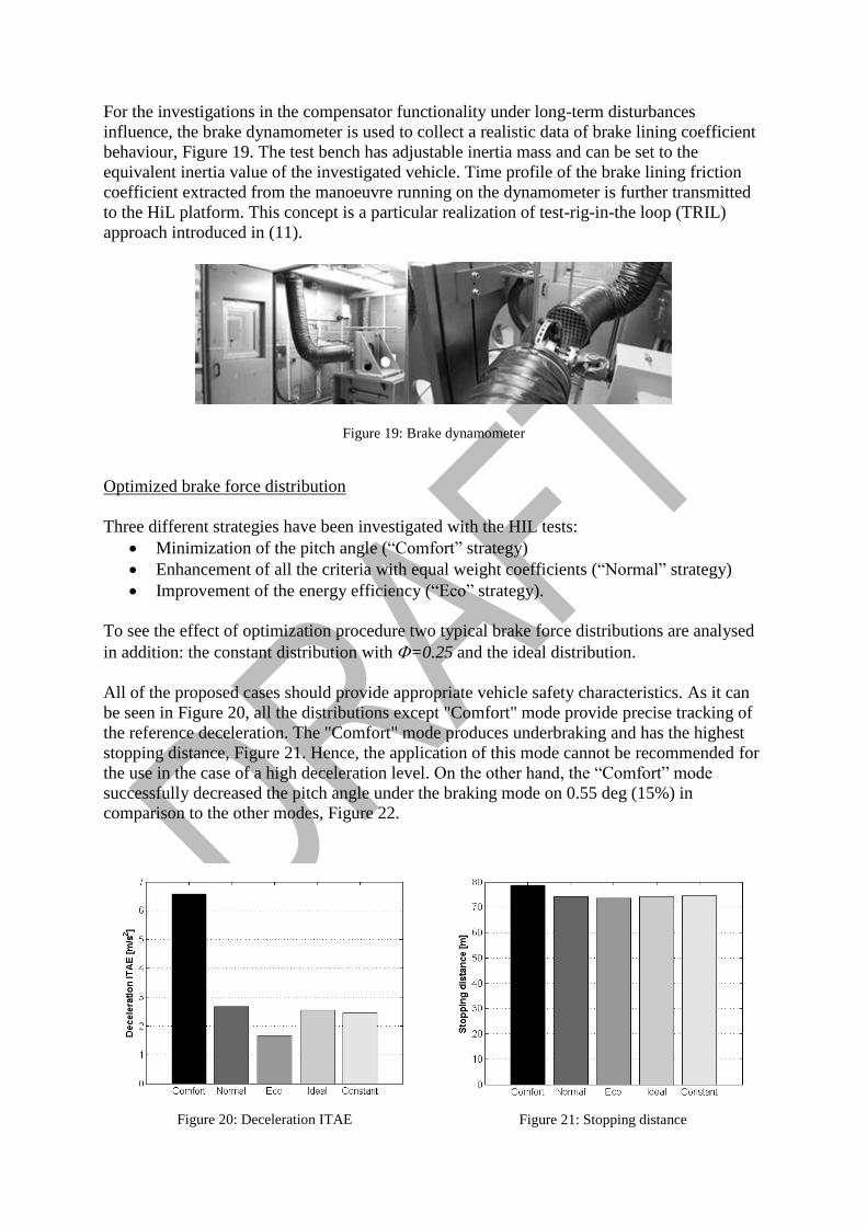
For the investigations in the compensator functionality under long-term disturbances
influence, the brake dynamometer is used to collect a realistic data of brake lining coefficient
behaviour, Figure 19. The test bench has adjustable inertia mass and can be set to the
equivalent inertia value of the investigated vehicle. Time profile of the brake lining friction
coefficient extracted from the manoeuvre running on the dynamometer is further transmitted
to the HiL platform. This concept is a particular realization of test-rig-in-the loop (TRIL)
approach introduced in (11).
Figure 19: Brake dynamometer
Optimized brake force distribution
Three different strategies have been investigated with the HIL tests:
Minimization of the pitch angle (“Comfort” strategy)
Enhancement of all the criteria with equal weight coefficients (“Normal” strategy)
Improvement of the energy efficiency (“Eco” strategy).
To see the effect of optimization procedure two typical brake force distributions are analysed
in addition: the constant distribution with =0.25 and the ideal distribution.
All of the proposed cases should provide appropriate vehicle safety characteristics. As it can
be seen in Figure 20, all the distributions except "Comfort" mode provide precise tracking of
the reference deceleration. The "Comfort" mode produces underbraking and has the highest
stopping distance, Figure 21. Hence, the application of this mode cannot be recommended for
the use in the case of a high deceleration level. On the other hand, the “Comfort” mode
successfully decreased the pitch angle under the braking mode on 0.55 deg (15%) in
comparison to the other modes, Figure 22.
Figure 20: Deceleration ITAE
Figure 21: Stopping distance

Figure 22: Pitch angle
Analysis of the energy efficiency criteria shows that the target of the "Eco" mode in
increasing recuperated energy is successfully achieved, Figure 23. The worst results in this
respect are observed for the "Comfort" mode. It should be especially noted that the conflict
between minimization of the tyre energy dissipation, Figure 24, and improvement of the brake
energy recuperation has been observed for all the modes. Thus, enhancement in energy
harvesting with simultaneous reduction of tyre friction losses could not be achieved by means
of the optimization of brake force distribution.
Figure 23: Recuperated energy
Figure 24: Tyre energy dissipation
The represented strategies according to the represented results can be described and used as
follows:
The “Eco” drive mode should be used as the strategy with maximal energy
recuperation, but does not supply minimization of the tyre energy dissipation due to
the criteria conflict;
The “Comfort” strategy has more limited application and can be applied during the
service braking;
The use of “Comfort” strategy on the high deceleration level is impossible and
optimization weights should be redistributed to achieve more vehicle safety;
The “Normal” strategy is represented as balanced compromise between all three
characteristics (ride comfort, energy efficiency and vehicle safety) and can be used
with any further controller composition as the basis configuration.

Disturbances Compensation
In addition to the represented brake force distribution strategies the compensation algorithm
dedicated to improve the tracking of deceleration and improve vehicle safety is approbated
using the HIL and brake dynamometer testing facilities. At the first stage the behaviour of the
brake lining friction coefficient was investigated considering the full load of hydraulic brake
system, Figure 25. In such conditions the coefficient of friction shows the maximal influence
on the brake performance. The testing procedure is carried out in accordance with standard
ISO26867 (12). It consists of 15 braking applications with deceleration of 0.4 g from the
initial velocity of 100 km/h in each case.
Figure 25: Fading effect
For the efficiency assessment of the proposed control strategy case of controller without
compensation mechanism is represented. In the both compensated and non-compensated
cases the friction coefficient is changing as in abovementioned testing procedure. The
manoeuvre is the same as in (12) and both vehicles have enough precise tracking of the
vehicle velocity to produce deceleration of 0.4 g. As it can be seen in the Figure 26 in non-
compensated case deviation of the actual deceleration from reference signal characterized by
ITAE is increasing with the friction coefficient degradation. The proposed compensation
mechanism successfully evaluates the correction factor represented in Figure 27 filtering it
from the other disturbances as rolling resistance and air drag force. At the end of the
manoeuvre according to the set of proposed rules for stepwise change of the correction factor
it reaches a four times better results than in the non-compensated case.
Figure 26: Deceleration ITAE
Figure 27: Correction factor

Hence, the proposed disturbance compensation algorithm successfully evaluates the
correction factor to avoid the loss of brake efficiency during long-term processes in particular
in case of fading. This control strategy working in parallel with the proposed distribution
strategies and has been tested with the real EHB system and brake prototype to gain further
improvements in vehicle safety
CONCLUSIONS
The presented study has introduced procedures of multi-criteria optimization of the brake
control of the electric vehicle in terms of safety, energy efficiency and ride comfort. It was
shown that the selective optimization of the brake force distribution can result either in
achieving of high level of brake energy regeneration of in reduction of the pitch angle during
the straight-line braking with simultaneous keeping of required vehicle deceleration. The
proposed optimization procedure was implemented in the base brake controller of electro-
hydraulic brake system advanced with external disturbances compensator. The functionality
of the developed controller was investigated using HIL technique in combination with brake
dynamometer. The obtained results can be used by for development of the integrated chassis
control systems of electric vehicles.
ACKNOWLEDGEMENTS
The research relates to the research group PORT at Ilmenau University of Technology funded
by the European Social Fund ESF (project No. 2011 FGR 0120). The electro-hydraulic brake
system and kind support in its tuning is provided by the TRW Automotive, Koblenz.
REFERENCES
(1) H. Fujimoto and S. Sato, "Pitching control method based on quick torque response for
electric vehicle," in Power Electronics Conference (IPEC), 2010 International, Sapporo,
2010, pp. 801-806.
(2) S. Sato and H. Fujimoto, "Proposal of pitching control method based on slip-ratio control
for electric vehicle," in Industrial Electronics, 2008. IECON 2008. 34th Annual
Conference of IEEE , Orlando, FL, 2008, pp. 2823-2828.
(3) T. Morita and T. Matsukawa, "Improvement of Vehicle Dynamics by Rear Braking Force
Control," Vehicle System Dynamics, vol. 24:4-5, pp. 401-412, 1995.
(4) Guo, J., Wang, J. and Cao, B. (2009) ‘Study on braking force distribution of electric
vehicles’, Proc. of Asia-Pacific Power and Energy Engineering Conference, APPEEC
2009, art. no. 4918806.
(5) N. Mutoh "Driving and braking torque distribution methods for front- and rear-wheel-
independent drive-type electric vehicles on roads with low friction coefficient", IEEE
Trans. Ind. Electron., vol. 59, no. 10, pp.3919 -3933 2012
(6) D. Savitski, B. Shyrokau, V. Ivanov. " Development of Base-Brake Controller with
Disturbances Compensation for Decoupled Electro-Hydraulic Brake System of Electric
Vehicle," International Journal of Mechatronics, 2014 (submitted)
(7) K. Augsburg, et al., "Test-rig-in-the-loop (TRIL) application to controllable brake
processes," in Proc. of Eurobrake Conference, Dresden, Germany, 2012.
(8) D. Savitski, V. Ivanov, L. Heidrich, K. Augsburg, and T. Pütz, "Experimental
investigations of braking dynamics of electric vehicles," in Proc. of Eurobrake 2013
Conference, Dresden, Germany, 2013.
(9) R. Rajamani, Vehicle dynamics and control. New York: Springer, 2006.
(10) L. Heidrich, B. Shyrokau, D. Savitski, V. Ivanov, K. Augsburg and D. Wang,
“Hardware-In-The-Loop test rig for integrated vehicle control systems,” Proc. 7th IFAC
Symposium on Advances in Automotive Control, Tokyo, Japan, 2013.
(11) K. Augsburg, et al., "Investigation of Brake Control Using Test Rig-in-the-Loop
Technique," SAE Technical Paper Series 2011-01-2372, 2011, doi:10.4271/2011-01-
2372.
(12) ISO26867, Friction behaviour assessment for automotive brake systems, 2008.
(13) F. Bottiglione, A. Sorniotti, and L. Shead, "The effect of half-shaft torsion dynamics
on the performance of a traction control system for electric vehicles," Proc IMechE Part
D: J Auto. Eng., 226 (9), pp. 1145-1159, 2012.