Design and Manufacturing of Gearbox for Four-Wheel Steering
11
International Research Journal of Engineering and Technology (IRJET) e-ISSN: 2395-0056 Volume: 09 Issue: 01 | Jan 2022 www.irjet.net p-ISSN: 2395-0072 © 2022, IRJET | Impact Factor value: 7.529 | ISO 9001:2008 Certified Journal | Page 356 Design and Manufacturing of Gearbox for Four-Wheel Steering Bhavesh Nandpure 1 B.Tech- Mechanical Engineering, MPSTME, Maharashtra, India ---------------------------------------------------------------------***---------------------------------------------------------------------- Abstract – The paper discusses about the design and production process of 4-Wheel Steering system. The basic motive behind this research is to improve the steering ability and effort required while turning the vehicle. This prototype of gearbox will reduce the turning radius of vehicle, manoeuvre in different terrains easily, and increase the stability of steering wheel while driving vehicles at high speeds. In this paper we have designed and discussed the manufacturing techniques of designed gearbox through which 4-Wheel Steer can be achieved. By using this system, it is possible for driver to control angles of four wheels. In this steering mechanism rear wheels turns in opposite direction with respect to front wheels at slow speed conditions while turning. This will result in low turning radius and prevent sliding on slippery terrains such as snow and rain covered roads. Similarly, at high speeds another gear system will get engaged, which will turn the rear wheel in the same direction as of front wheel providing a smooth turn at high speeds. An attempt is made to formulate this gear box by using rack and pinion steering system with certain controllers and actuators to automate the gear engaging process. The paper shows a methodology to achieve a suitable manufactured prototype of four-wheel steered gearbox and discuss the benefits of this system. Key Words: Turning Radius, Spur Gear, Bevel Gear, Gear box, Rack and Pinion, Wheelbase, and Track width. 1.INTRODUCTION 1.1. What is a steering system? Steering system is a group of linkages between components that turn the rotary motion of steering wheel into a linear motion, accompanying the wheels of the vehicle to turn at different angles either on right or left side. The steering system includes a driver controlled steering wheel, motion conversion steering gear to translate rotary motion to linear motion, and the steering linkages that transmit motion from steering wheel to wheels. The most commonly used steering system types are rack and pinion and recirculating ball type. These systems used to be manual type earlier but nowadays almost all vehicles have power steering, which is convenient to reduce the steering effort of driver. The basic components of power steering system include steering wheel, steering angle sensor, speed sensor, input shaft, intermediate shaft, tie rods, knuckle, steering gear assembly, steering shaft electronic control unit (ECU), solenoid valve, oil pump, tank etc. The good steering system has good accuracy, light and easy to handle, directional stability, minimum turning effort, less or no shock transmission from road surface to driver’s hand. The general arrangement of every steering system contains steering wheel, steering column, steering shaft, steering gear box, drop arm, pull and push rod or drag link, knuckle arm, Tie rod. 1.2. Working of front wheel Steering system The steering wheel is used to rotate the steering column which later rotates the gears in gearbox at the end of column. The cross shaft in gearbox is connected to drop arm and it is connected to steering arms by means of drag link. The arms operate the tie rods which are joined to knuckle that moves the wheel left and right. A ball socket joint is used to join tie rod and drop arm. In case of vibrations while travelling drop arm vibrates and therefore springs are used in ball sockets to damp vibrations from the surface of roads to steering wheel. 1.3. Types of Steering Mechanism The steering mechanisms are classified based on their geometry. They are Davis steering mechanism and Ackermann steering mechanism. Davis steering system consists of sliding pairs which wears out due to friction and hence changes the accuracy with time. Ackermann steering system consists of turning pairs hence it has better life as it does not wear easily. Therefore, Ackermann is most preferred mechanism for steering. In Ackermann steering system the end of the axle has a spindle that attaches to kingpin. The linkages form a shape of trapezoid after connecting spindle. When the front and rear wheels get parallel, they are in straight line. However, when wheels are turned, inner wheel turns by greater angle than external causing external wheel to cover a greater distance than inner wheel. The amount of steer angle is dependent on the ratio of trackwidth and wheelbase in Ackermann based steering system. The system holds true for left, right and straight position but consists of small error in other positions. 1.4. Problems with Front Wheel or 2WS system: There are various automatic controlled systems in modern vehicles to reduce the efforts of driver. But the automation found in steering control is less while it plays a major role in safety of passengers. Almost majority of people in the world still have vehicles having front wheel steering system which causes several problems such as, when it comes to turning of vehicle for parking in narrow spaces or in parallel parking condition. The most of the drivers find it quite cumbersome and difficult to park as they require to steer the wheels frequently. As they steer to turn, they move the wheels at various angles too often, but could only achieve a small turn as the rear wheels are always straight. Hence, most of the
-
Upload
khangminh22 -
Category
Documents
-
view
0 -
download
0
Transcript of Design and Manufacturing of Gearbox for Four-Wheel Steering

International Research Journal of Engineering and Technology (IRJET) e-ISSN: 2395-0056
Volume: 09 Issue: 01 | Jan 2022 www.irjet.net p-ISSN: 2395-0072
© 2022, IRJET | Impact Factor value: 7.529 | ISO 9001:2008 Certified Journal | Page 356
Design and Manufacturing of Gearbox for Four-Wheel Steering
Bhavesh Nandpure1
B.Tech- Mechanical Engineering, MPSTME, Maharashtra, India ---------------------------------------------------------------------***----------------------------------------------------------------------Abstract – The paper discusses about the design and production process of 4-Wheel Steering system. The basic motive behind this research is to improve the steering ability and effort required while turning the vehicle. This prototype of gearbox will reduce the turning radius of vehicle, manoeuvre in different terrains easily, and increase the stability of steering wheel while driving vehicles at high speeds. In this paper we have designed and discussed the manufacturing techniques of designed gearbox through which 4-Wheel Steer can be achieved. By using this system, it is possible for driver to control angles of four wheels. In this steering mechanism rear wheels turns in opposite direction with respect to front wheels at slow speed conditions while turning. This will result in low turning radius and prevent sliding on slippery terrains such as snow and rain covered roads. Similarly, at high speeds another gear system will get engaged, which will turn the rear wheel in the same direction as of front wheel providing a smooth turn at high speeds. An attempt is made to formulate this gear box by using rack and pinion steering system with certain controllers and actuators to automate the gear engaging process. The paper shows a methodology to achieve a suitable manufactured prototype of four-wheel steered gearbox and discuss the benefits of this system.
Key Words: Turning Radius, Spur Gear, Bevel Gear, Gear box, Rack and Pinion, Wheelbase, and Track width.
1.INTRODUCTION
1.1. What is a steering system?
Steering system is a group of linkages between components that turn the rotary motion of steering wheel into a linear motion, accompanying the wheels of the vehicle to turn at different angles either on right or left side. The steering system includes a driver controlled steering wheel, motion conversion steering gear to translate rotary motion to linear motion, and the steering linkages that transmit motion from steering wheel to wheels. The most commonly used steering system types are rack and pinion and recirculating ball type. These systems used to be manual type earlier but nowadays almost all vehicles have power steering, which is convenient to reduce the steering effort of driver. The basic components of power steering system include steering wheel, steering angle sensor, speed sensor, input shaft, intermediate shaft, tie rods, knuckle, steering gear assembly, steering shaft electronic control unit (ECU), solenoid valve, oil pump, tank etc. The good steering system has good accuracy, light and easy to handle, directional stability, minimum turning effort, less or no shock transmission from road surface to driver’s hand. The general arrangement of every steering system contains steering wheel, steering column, steering shaft,
steering gear box, drop arm, pull and push rod or drag link, knuckle arm, Tie rod.
1.2. Working of front wheel Steering system
The steering wheel is used to rotate the steering column which later rotates the gears in gearbox at the end of column. The cross shaft in gearbox is connected to drop arm and it is connected to steering arms by means of drag link. The arms operate the tie rods which are joined to knuckle that moves the wheel left and right. A ball socket joint is used to join tie rod and drop arm. In case of vibrations while travelling drop arm vibrates and therefore springs are used in ball sockets to damp vibrations from the surface of roads to steering wheel.
1.3. Types of Steering Mechanism
The steering mechanisms are classified based on their geometry. They are Davis steering mechanism and Ackermann steering mechanism. Davis steering system consists of sliding pairs which wears out due to friction and hence changes the accuracy with time. Ackermann steering system consists of turning pairs hence it has better life as it does not wear easily. Therefore, Ackermann is most preferred mechanism for steering. In Ackermann steering system the end of the axle has a spindle that attaches to kingpin. The linkages form a shape of trapezoid after connecting spindle. When the front and rear wheels get parallel, they are in straight line. However, when wheels are turned, inner wheel turns by greater angle than external causing external wheel to cover a greater distance than inner wheel. The amount of steer angle is dependent on the ratio of trackwidth and wheelbase in Ackermann based steering system. The system holds true for left, right and straight position but consists of small error in other positions.
1.4. Problems with Front Wheel or 2WS system:
There are various automatic controlled systems in modern vehicles to reduce the efforts of driver. But the automation found in steering control is less while it plays a major role in safety of passengers. Almost majority of people in the world still have vehicles having front wheel steering system which causes several problems such as, when it comes to turning of vehicle for parking in narrow spaces or in parallel parking condition. The most of the drivers find it quite cumbersome and difficult to park as they require to steer the wheels frequently. As they steer to turn, they move the wheels at various angles too often, but could only achieve a small turn as the rear wheels are always straight. Hence, most of the

International Research Journal of Engineering and Technology (IRJET) e-ISSN: 2395-0056
Volume: 09 Issue: 01 | Jan 2022 www.irjet.net p-ISSN: 2395-0072
© 2022, IRJET | Impact Factor value: 7.529 | ISO 9001:2008 Certified Journal | Page 357
drivers feel parking tiresome activity despite having parking assistance, 360˚ vehicle view, front and back sensors.
Another common scenario where front wheel system fall short is during turning of vehicles at high speeds. At high speeds driver have to reduce the speed of vehicle to take a turn so that they maintain stability of vehicle and vehicle does not get skid off the track. This scenario has remained a disadvantage for racing drivers for years who need to constantly decelerate and accelerate the vehicle at turns or while switching lanes on tracks. The turning radius has always remain large for the front wheel steering system and so now there is a need of replacement of this system with new all wheel steering system.
The above problems can be solved by using a 4-Wheel steering system, where the angles of all wheels can be adjusted automatically or manually using a special gear arrangement.
1.5. What is 4-Wheel Steering (4WS) system?
A 4WS system consists of front steering controlled by power steering system which can be either hydraulic or electronic and at rear there is a rear steering mechanism which is controlled by means of gearbox or gear arrangement depending on the speed of vehicle and steering angle of wheel. The electronic form of transmitting motion through hydraulics can also be done in rear steering mechanism which is termed as rear power steering. In this system at rear a gear used for reciprocating rack, consists of spring which always return to its initial position after turning. This assures that the rear wheels remain straight after turning is completed, the spring used here is termed as self-centering spring which plays a crucial role when there is a failure of hydraulic system of rear power steering. As the self-centering spring brings back the pinion to initial position making the rear wheel straights after turning, the failure of hydraulics will not have significant effect while turning as the front wheel can be easily steered or get transformed to 2-Wheel Steering (2WS) system after failure of 4WS.
Our designed 4WS mechanism consists of rack and pinion mechanism at front and rear, where front rack is controlled by driver and the rear rack is controlled by a gear arrangement consisting 4 spur gears and 3 bevel gears which is connected to electronic control unit, actuators and sensors to operate itself depending on the speed of vehicle and angle of front steer. The rear wheels turn in opposite direction with respect to front wheels in slow speed conditions while making a turn. This will result in low turning radius and prevent sliding or skidding of vehicle off the track. In addition, when they turn in opposite direction at slow speeds, they could achieve a good grip between road surface and tires resulting no slip in snowy terrains. Also, it will be beneficial while driving on hilly areas where turns are quite sharp and in cities or congested areas while taking U-turn. Similarly, at high speeds another gear arrangement will be used, where rear wheels will turn in same direction as of
front wheel, providing a smooth turn at higher speeds. This turning of 4WS system is also termed as ‘In-phase’ (at higher speeds) and ‘Counter-phase’ (at slow speeds) as shown in figure 1.1 and 1.2.
Fig.1.1 Counter-phase steering (at slow speed)
Fig.1.2 In-phase steering (at high speed)
The basic motive behind 4-Wheel Steering system is to improve the steering ability and decrease effort required while turning vehicle. The designed all wheel steering gearbox will reduce the turning radius of vehicle, manoeuvre in different terrains easily and increase the stability of steering wheel while driving at high speeds. We have designed and manufactured an automated gear arrangement or gearbox through which four wheels can be steered. By using this system, it is possible for driver to control angles of all four wheels.

International Research Journal of Engineering and Technology (IRJET) e-ISSN: 2395-0056
Volume: 09 Issue: 01 | Jan 2022 www.irjet.net p-ISSN: 2395-0072
© 2022, IRJET | Impact Factor value: 7.529 | ISO 9001:2008 Certified Journal | Page 358
1.6. Benefits and need for 4-Wheel Steering System
1.6.1 Low Turning Speeds
Fig.1.3 Difference in turning radius of 2-Wheel or front Wheel steering and 4-Wheel steering system [4]
For 2WS the turning radius can be seen to be large when compared with 4WS. The significant change is seen in position of point ‘O’ in the figure which is also Instantaneous center of rotation (ICR). The point ‘O’ remained on the axis of rear wheels in 2WS which resulted in more turning radius and greater width to take turn. While in 4WS the rear wheel turned in opposite direction with respect to front wheel, changing the position of ICR to middle. Hence, from geometry it can be seen that the turning radius and the width to take turn is reduced. This condition holds true for slow speeds to take turn on narrow passes and U-turns.
1.6.2 High-speed Turning
Vehicles require more cornering force (C) at high speeds to balance centrifugal force, which is more for vehicle at higher speed taking a turn. As the cornering force increases the side slip angle also increases for 2WS system. But in 4WS system as rear wheels gets steered on same curve with front wheels at high speeds, it reduces yawing of vehicle and prevent it from moving outside the curve. This results in reduced yawing time or time to get stabilized and reduction in slip angle. The side-slip angle is greater for 2WS system than 4WS system.
Fig.1.4 Difference in centrifugal and cornering force acting in 2WS and 4WS at high speeds [4]
1.6.3 Lane change
Fig.1.5. Lane change scenario for 2WS vs 4WS [4]
The length of time required by 2WS system to stabilize rear wheel is more than 4WS system. As the 2WS system goes yawing while changing lane it needs to be steered in opposite direction so that rear wheels get aligned quickly. In case of 4WS system it has good balance while changing lanes and has a precise steering at corners, as the rear wheels also gets steered independently with respect to front wheels decreasing the chances of stumbling.
2. DESIGN AND CALCULATIONS
The designing and manufacturing of gear box is implemented for the standard hatchback vehicle with the dimensions given below. In the paper I have taken into consideration the standard dimensions of Maruti Suzuki Alto. However, a similar prototype was designed with same gear arrangement, dimensions and is tested for the four-
International Research Journal of Engineering and Technology (IRJET) e-ISSN: 2395-0056
Volume: 09 Issue: 01 | Jan 2022 www.irjet.net p-ISSN: 2395-0072
© 2022, IRJET | Impact Factor value: 7.529 | ISO 9001:2008 Certified Journal | Page 359
wheel drive system for its implementation. It was later found to be successful and below are the calculations shown for the prototype.
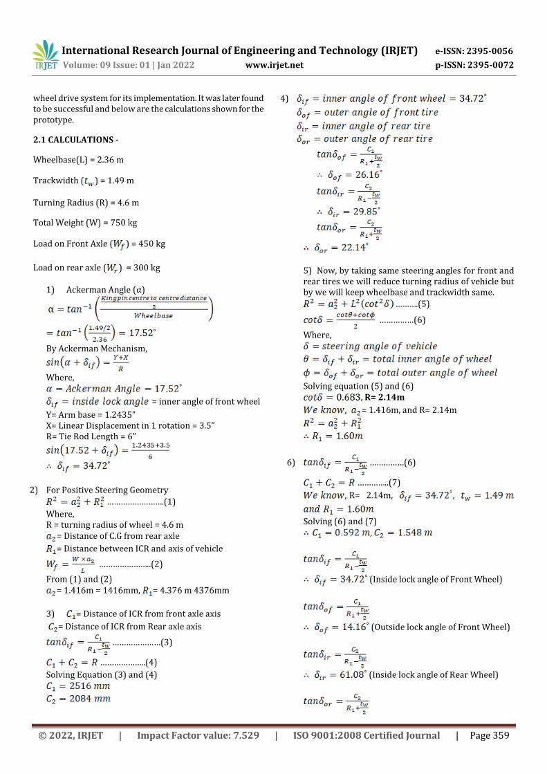
2.1 CALCULATIONS -
Wheelbase(L) = 2.36 m
Trackwidth ( ) = 1.49 m
Turning Radius (R) = 4.6 m
Total Weight (W) = 750 kg
Load on Front Axle ( ) = 450 kg
Load on rear axle ( ) = 300 kg
1) Ackerman Angle (α)
˚
By Ackerman Mechanism,
Where,
= inner angle of front wheel
Y= Arm base = 1.2435” X= Linear Displacement in 1 rotation = 3.5” R= Tie Rod Length = 6”
2) For Positive Steering Geometry
…………………….(1)
Where, R = turning radius of wheel = 4.6 m
= Distance of C.G from rear axle
= Distance between ICR and axis of vehicle
…………………..(2)
From (1) and (2) = 1.416m = 1416mm, = 4.376 m 4376mm
3) = Distance of ICR from front axle axis
= Distance of ICR from Rear axle axis
…………………(3)
………………..(4)
Solving Equation (3) and (4)
4)
5) Now, by taking same steering angles for front and rear tires we will reduce turning radius of vehicle but by we will keep wheelbase and trackwidth same.
……….(5)
……………(6)
Where,
Solving equation (5) and (6) , R= 2.14m
= 1.416m, and R= 2.14m
6) ……………(6)
…………..(7)
R= 2.14m, ,
Solving (6) and (7)
(Inside lock angle of Front Wheel)
(Outside lock angle of Front Wheel)
(Inside lock angle of Rear Wheel)

International Research Journal of Engineering and Technology (IRJET) e-ISSN: 2395-0056
Volume: 09 Issue: 01 | Jan 2022 www.irjet.net p-ISSN: 2395-0072
© 2022, IRJET | Impact Factor value: 7.529 | ISO 9001:2008 Certified Journal | Page 360
(Outside lock angle of (Rear Wheel)
= 95.8˚ (Total inner angle of vehicle)
(Total outer angle of
vehicle)
……….(8)
……………(9)
Solving equation (8)
Solving equation (9) R= 1.70 m
The figure 2.1 shows the angles of the front wheels which will be the input parameters in our steering system. To locate Instantaneous Centre of Rotation (ICR), we have drawn a perpendicular line from centre of front axle. Then similarly the steer angle of rear wheels was checked where they come out to be approximately the
same. For example, , and
, but in Figure it
was found and which are
nearly the same. In the same way, the distance of CG from
rear axle ( is located and verified for turning radius it
is equal to 1.64 (from figure) and 1.70 (from calculations)
Fig.2.1. Line Diagram for calculated values of 4WS
7) Steering ratio (n)
a = Steering wheel angle = 360˚ (for one rotation of steering wheel)
8) Rack and Pinion Calculation
For Pinion,
α= Pressure Angle = 20˚ = fraction to multiply addendum of wheel = 1
= 1.66
= 1.5
(T)
14 teeths
For Rack,
Linear Displacement of rack for 1 Rotation of
pinion= = 141.37 mm
PCD= Pitch Circle Diameter = m = 45 mm
Mounting Distance = 55 mm (from Design) H= Rack height We Know,
9) Bevel Gear Calculation
= 70
= = 90
= Pitch Circle Diameter of Pinion
= Pitch Circle Diameter of Gear
α= Pressure Angle = 20˚ = Ultimate Tensile Strength = 700 MPa
= 1.5
Y= Lewis Form factor
= Wear Strength

International Research Journal of Engineering and Technology (IRJET) e-ISSN: 2395-0056
Volume: 09 Issue: 01 | Jan 2022 www.irjet.net p-ISSN: 2395-0072
© 2022, IRJET | Impact Factor value: 7.529 | ISO 9001:2008 Certified Journal | Page 361
BHN = Brinell hardness number k= Load stress factor
= 88.67
= 0.4412
= 233.33
= m = 105 mm
= m = 135 mm
= 85.51 mm
= 1909.95
Wear Strength
= 1.246
= 2.6896
= 6686.3 N
10) Spur Gears
= 700 Mpa
= m = 75 mm
= m = 87.5 mm
= 12.5 mm
= 233.33
= 1534.87 N
= 1.077
k = 2715.65 N
KW= Power transmitted by gears = 0.05KW = 50 Watts n = number of revolutions = 10 rpm (Assumed)
by gears
= Tangential component of tooth force
= Radial component of tooth force
= 47746.48 N-mm
= 1273.24 N
= tanα = 463.42 N
= 1273.24 N
= 463.42 N
a)
b) × 120 + × 300 = × 180
= +
2.2 DESIGN –
The prototype is designed using Dassult Systems-SolidWorks.
Fig.2.2. Assembled 4WS in Solidworks Rendering

International Research Journal of Engineering and Technology (IRJET) e-ISSN: 2395-0056
Volume: 09 Issue: 01 | Jan 2022 www.irjet.net p-ISSN: 2395-0072
© 2022, IRJET | Impact Factor value: 7.529 | ISO 9001:2008 Certified Journal | Page 362
Fig.2.3. Arrangement of gear for In-phase Steer
Fig.2.4. Arrangement of gear for Counter-Phase
Fig.2.5. Gear Box Design in Solidworks Rendering
Fig.2.6. Technique to Implement 4WS Gear Box in an Automobile with Sensor positions
After studying the Circuit Diagram of Alto 800, I came to know that C02-4-40 was the module responsible for power steering unit in Maruti Suzuki Alto. So, if the changes in circuit have to be done in future this module needs to be replaced. This module carries function of VSS (Vehicle speed sensor) and measures the transaxle output of speed of the wheel. By using speed of vehicle as input the functions such as ignition timing, air-fuel ratio, transmission shift, actuating steering for 4WS can be adjusted.
3. MANUFACTURING PROCESS INVOLVED
3.1Manufacturing processes used for Steering Components
Steering wheel is manufactured using steel ring that is welded on hub with certain spokes. The ebonite is moulded after welding the wheel to enhance look and provide grip to hands. Then splines and groove are created at bottom to attach to shaft.
Steering column is a hollow steel pipe of mild steel which is housed with outer casing. One end of pipe is attached to gear box of steering and another to bracket.
Steering shaft is manufactured using good quality steel, where one end is inside steering wheel and the other has splines or key-lock arrangement to keep it attached by worm or bevel gear of gear box.
Steering gearbox consists of casing made of aluminium and gears are either bevel, spur, rack and pinion type made of high strength steel or cast iron. Its function is to convert rotary motion to linear motion and is connected to drop arm.
Drop arm is manufactured using forged steel. It has splines which attaches sector-shaft by nut and other end with ball joints and nut.
Following production methods are used for making Steering Components

International Research Journal of Engineering and Technology (IRJET) e-ISSN: 2395-0056
Volume: 09 Issue: 01 | Jan 2022 www.irjet.net p-ISSN: 2395-0072
© 2022, IRJET | Impact Factor value: 7.529 | ISO 9001:2008 Certified Journal | Page 363
3.1.1. Broaching It is a metal cutting process, where metal is removed by slender rod having series of cutting edges. It has increasing protrusion containing number of cutting and finishing teeths. Broaching makes it feasible to remove the entire non-required material in a single stroke, as it has increasing height from bottom to top. Straight thorough holes can be created using this tool. The broaching is used in creating external and internal teeths of spur gears. The two types of broaches used dominantly are of push and pull types, they are made of various cross sections and rising heights of teeths. Push type broaches are usually short in length to prevent them from buckling due to compressive force on it. The materials used to make broaches have good strength, wear resistance, toughness, and hardness. The most of the typical material used to make broaching tools are high speed steel (HSS), cemented carbide, and TiN coated carbides. Nowadays, replaceable inserts are used to increase the life of tool. Further, broaches are classified on basis of internal, external, pull type, push type, and ordinary or progressive type.
Fig.3.1. Broaching Tools 3.1.2. Heat Treatment This is type of metalworking process for changing properties of metal. It involves heating and cooling of material to extreme temperatures to achieve results of hardening or softening. The basic processes involved are annealing, case hardening, tempering, carburizing, normalizing and quenching. After the required dimensions of gear material are cut, it will be sent for heat treatment to increase its strength and to optimize the characteristics of metal.
Fig.3.2. Vacuum Heat Treatment Machine[6]
3.1.3. Milling A significant number of metals can be cut using milling operation. Most of the designed parts can be manufactured using milling techniques. The most milling operations carried these days can be done using Vertical machining centre (VMC). The two types of milling machine which were used were Horizontal milling machine and Vertical milling machine. They required lots of effort by operator to move spindle in opposite direction of the rotation of cutting wheel. The shaping and planning operations can be also done using milling machine. Various cutting tools are used in milling machine for various purposes such as Slab mills, Side and face cutters, Slitting saws, End Mills, Slot drills, Involute gear cutter, Hobbing cutter etc. Before sending our gears for heat treatment we will be machining them roughly and generate teeths using Hobbing cutter. This process will be carried on milling machine. Milling types Tools used Application Horizontal Milling
Slab Mills Requiring large cutting of flat surfaces
Side and Face Cutters
Cutting of shoulders and slots
Slitting Saws Generating deep slots and parting off surfaces
Vertical Milling
End Mills Facing, Slotting, Profile Milling
Rough cut end Mills
Rapid material removal rate
Slot Drills Producing pocket for drilling holes
Face milling cutters
Heavy cutting
Gear Cutters Involute gear cutter
Generating involute profiles
Hobbing Cutter
It has a cross section with milling teeths used to create desired shape. Also known as specialised milling machine
Table.1 Types of tools used in Milling operation 3.1.4. Turning These operations are carried on lathe machine where the job or workpiece rotates and the tool moves linearly on axis of rotation. The basic operations carried on lathe machine are turning, drilling, facing, grooving, threading, knurling, parting, chamfering and taper turning. In turning operation, the excess material is removed to reduce the diameter of workpiece. While, in facing the face of workpiece is made flat or it’s done to reduce length of circular workpiece. Knurling is done to generate rough textured surface for functional or decorative purpose. Grooving is done to generate groove on workpiece. Parting is done to cut the workpiece. Various tools used for different turning operations they are Single point cutting and turning tool, Knurling tool, Form tool, Parting tool, Chamfering tool, Form tool, Drill Bits etc. On the

International Research Journal of Engineering and Technology (IRJET) e-ISSN: 2395-0056
Volume: 09 Issue: 01 | Jan 2022 www.irjet.net p-ISSN: 2395-0072
© 2022, IRJET | Impact Factor value: 7.529 | ISO 9001:2008 Certified Journal | Page 364
lathe machine we will be performing facing and turning operation to make the faces of gears flat and to make them dimensionally accurate. Boring is also done using Lathe machine to fix gear on shafts. Turning Operations Tools used Facing + Turning Single point turning tool Knurling Knurling tool Grooving Form tool Parting Parting tool Chamfering Chamfering tool 45˚ Taper Turning Form tool Drilling Drill bits
Table.2 Types of tools used in Turning Operation
Fig.3.3. Lathe Machine
3.1.5. TIG (Tungsten Inert Gas) welding It is a type of electric arc welding process, the fusion occurs between workpiece and tungsten electrode. The inert gas from nozzle is continuously sprayed on welding area to protect it against atmospheric air and prevent it from oxidation. In this process the electrode used does not get consumed as in MIG (Metal Inert Gas Welding) process. The tungsten electrode is connected to the negative terminal and workpiece to the positive. The principal of TIG states that negatively charged electrons will move towards positive pole and ions to negative pole. As a result, there will be collision between electrons and ions, which will generate heat and cause fusion of particles. As the speed of electrons and ions is very high, substantial amount of heat is generated. Metals like stainless steel, aluminium, nickel and its alloys can be easily welded by TIG. We will use TIG welding to weld our chassis on which the all the components will be welded 3.1.6. Grinding It is a type of material removal process, but the material removal is comparatively smaller in volume. The tool used has many small cutting edges, which cut metal with high dimensional accuracy and generate good surface finish. The two types of grinding machines used are rough grinding and precision grinding machine.
Rough Grinding- is used to remove stock which is excess. It is carried out randomly and has little or no accuracy. For example: in casted parts, welded joints, etc. The types of rough grinders used are hand grinder, bench grinder, floor grinder, swing frame grinder and abrasive belt grinder. Precision Grinder- it is used to obtain good surface finish with high accuracy. The type of precision grinders used are cylindrical grinders, internal grinders, surface grinders, tool and cutter grinders. In Gear grinding, teeths of gear are grinded using a form grinding wheel having a shape of wheel saucer and it is used to grind two successive faces of the teeth.
Fig.3.4. Bench Grinder
3.1.7. Splines generation Both external and internal splines can be generated on shafts, gears and on other parts. Splines are generated to transmit power from one component to another. They act as a keyways which are machined to mate parts. The process involved in manufacturing of splines are Broaching, Hobbing, Milling and shaping. The internal splines will be generated on our gears and on the external face of shafts to hold the gears. Manufacturing of Gears Operations needed Gear cutting process Hobbing, Shaping, Planing,
Milling Gear finishing process Grinding, Shortblasting,
Phosphate coating Gear forming (non-cutting) process
Extrusion, Powder Metallurgy, Stamping, Casting
Table.3 Manufacturing techniques of gears
Sheet Metal Operations The different types of sheet metal operations involved are shown in the table given below. For manufacturing of gear housing, we have used the operations like shearing, bending and embossing. Blanking will be done on faces which will pass through shafts and bearings.

International Research Journal of Engineering and Technology (IRJET) e-ISSN: 2395-0056
Volume: 09 Issue: 01 | Jan 2022 www.irjet.net p-ISSN: 2395-0072
© 2022, IRJET | Impact Factor value: 7.529 | ISO 9001:2008 Certified Journal | Page 365
Table.4 Sheet metal operations based on induced stresses
4. Assembly of components
Firstly, the carriage or the buggy is made of the required dimensions mentioned in design section. It is made from square tubes of mild steel. The tubes are welded using TIG welding method. Later the rack and pinion is mounted in the holes made on square tube. The racks and pinion assemblies are made of EN 26 HSS, Similarly, another rack and pinion assembly is mounted on the rear end of buggy. The tie rods are attached at two ends of rack, which are made from EN 19 Steel. The frontal rack consists of teeths on two faces. On one face the pinion which is welded at end of steering column rotates and on another the spur gear attached to shaft rotates. This spur gears are made of cast iron. The shaft or mild steel rod has 2 spur gears fastened on both the ends. They are attached by using internal spline on gears and external splines on shaft. Behind the spur gear at other end of shaft there is bevel gear attached in a similar way to shaft. At the rear end the rack has teeths only on one face on which spur gear (pinion) rotates when gears are engaged. In the same way another spur gear is at the end of the shaft followed by a bevel gear. The gear arrangement is shown in figure above. The wheel assembly is attached to tie rods to allow them to turn. The pedestal bearing is used to hold this main shaft in the locations between front and back steering. Another shaft which is parallel to main shaft contains 2 spur gears which are inline with the spur gears on main shaft. Other shaft on other side is perpendicular and holds the large bevel gear which can engage with other two bevel gears on main shaft. Behind the large bevel gear there is a disc attachment, while the gears on parallel shaft is hold in fixture which is made using mild steel. All this assembly is covered using housing made of aluminium sheet that is bended to make housing. Bearings are attached in housing through which all these shafts will pass. Then, the fixture and disc is attached by electro-mechanical actuators attached to housing, this will ensure engagement and disengagement of gears. The actuators are connected to ECU which further controls relay and timer circuit to allow switching action. ECU is further connected to speed sensors which are placed on four wheels and near steering column. The input rpm is sent to ECU to decide the switching action of actuators. The whole circuit is connected by means of 12 V lead-acid battery. The rear pinion is attached to a spring, so that the initial position of it always remain to centre after turning. Initially, the position of gears is disengaged, where it acts as a 2WS. In the 2WS all the gears are in disengaged position.
When the vehicles start moving slowly first switching takes place wherein the spur gears on parallel shaft gets engaged with the spur gears on main shaft. When the vehicle moves at speed above 60 Km/hr the second switching action takes place where the spur gears in gearbox are disengaged and the bevel gears get engaged. This action of switching gears at different speeds completes the assembly of automated steering gearbox for 4WS.
5. Prototype Cost Estimation
Component Name
Specifications Quantity
Cost
Rack 1.5M 50T 20PA 20FW 32.5PH
2 4000
Pinion 1.5M 30T 20PA 20FW
2
Spur gear 1 1.25M 60T 20PA 12.5FW
4 1200
Spur Gear 2 1.25M 70T 20PA 12.5FW
2 700
Bevel Gear 1 1.5M 70GT 90PT 20PA 15FW
2 700
Bevel gear 2 1.5M 90GT 70PT 20PA 15FW
1 900
Ball Bearing 1 ISO 15 ABB-4820-Full
5 2200
Ball Bearing 2 ISO 15 ABB-4912-Full
8 2500
Roller Bearing ISO 15 RCR-6920-Full
4 4800
Pedestal Bearing
SKF P 20 FM 3 1500
Aluminium Plate
1m X 1m X 1mm 1 1700
Tyres (Used) 145/ 80R 12 4 5000
Rims (Used) 4J x 12 ET 45 4 5200
Mild Steel Circular Rod
20 x 20 ft. 1 2200
Mild Steel Square tube
27.5mm x 20ft. t=2mm
4 2800
Table.5 Estimated Mechanical Components cost
Estimated Mechanical Components Costs = 36,600 Rs Component Name
Specifications Quantity Cost
Electronic Control Unit (ECU)
- 1 8500
Speed Sensors 10V-14V, 1Hz-400Hz, 2 p/rot.
5 1000
Relay 12V Switch Delay Module
1 200
Timer Circuit 12V Switch Digital Module
1 600
Actuator 12 V Push Pull 2 2400
Types of Stress Operations Shear Shearing, Blanking, Piercing,
and trimming Tension Stretch forming Compression Coining, Sizing Tension and Compression
Drawing, Bending and Forming

International Research Journal of Engineering and Technology (IRJET) e-ISSN: 2395-0056
Volume: 09 Issue: 01 | Jan 2022 www.irjet.net p-ISSN: 2395-0072
© 2022, IRJET | Impact Factor value: 7.529 | ISO 9001:2008 Certified Journal | Page 366
Solenoid
Battery (Used) 12V Exide 1 8000
Table.6 Estimated Electrical Components cost
Estimated Electronic Components Cost - 20,700 Rs.
Estimated Total Prototype Cost – 57,300 Rs.
6. CONCLUSIONS
In conclusion, the research paper has shown a methodology for manufacturing and designing of gear box for four-wheel steering system. The new steering gear-box is also automated with the help of various sensors, electronic control unit and actuators making the steering system a semi-automatic one. The turning radius of the vehicle was reduced from 2.14m to 1.64m, decreasing nearly 20% of turning radius of vehicle. Manufacturing processes discussed above can be implemented to manufacture such type of gearboxes in automotive industries. The prototype cost estimation shown concludes with the minimum estimated rise in prices of cars having 2WS system when replaced with 4WS system. The minimum difference between 4WS cars and 2WS cars will be around 23,000 Rs. This new vehicle technology of implementing steering gear box will help the drivers of vehicle to drive comfortably and turn their vehicles in less radius, that means the vehicle will be easy to park in narrow areas, and take a turns at high speeds. The designed prototype gearbox can be successfully implemented in commercial vehicles and other automobiles making steering system more user friendly.
7. REFERENCES
Websites
[1]https://mojocommerce-digital-files-production.com
[2] https://www.snnemabroach.com/broaching-tool.html
[3] igitsarang.com
[4] Steering system-manuals.wibla.net
[5] https://autotech786.myinstamojo.com/
[6] indiamart.com
[7] https://www.custompartnet.com/
[8] https://www.youtube.com/watch?v=Z7zNcDj_YeA
Books and Educational Resources
[9] V.B Bhandari-Mc Graw Hill Education, “Design of Machine Elements-fourth edition” ISBN 978-93-392-2112-6
[10] R.S Khurmi, J.K Gupta- S.Chand ,“Theory of Machines”, ISBN 978-81-219-2524-2
[11] https://nptel.ac.in/
Research papers and projects
[12] Rajiv Chaudhary, R.C. Singh, “Study of 4 Wheel Systems to reduce turning radius and increase stability”, ICARI- January 2014, ISBN 978-93-5156-328-0
[13] Afthab P Shamsudheen, Hijas B S, “Four mode steering system for a four wheel vehicle”, IJARIIE-Vol 6 Issue-3 2020, ISSN-2395-4396
[14] Nitish Laad, Pranav Agrawal, “Design of four wheel active steering”, IJRAME-Vol.4 Issue 6, June 2016, ISSN 2321-3051
[15] Subramanyam B, P. Bridjesh, “Manufacturing of Steering components for race car”, IJMET-Vol.8, Issue 6, June 2017, ISSN 0976-6359
[16] Yonas Mitiku Degu, Defaru Thomas,“Design and manufacturing of mechanical steering system for parallel parking, zero turning radius, minimum turning radius with traditional turning’, STAR-Jan-March 2016, ISSN 2226-7522
[17] Suraj Bobade, Rushab Kumat, “Design and fabrication of Mechanical Car with the help of internal gear to obtain zero degree rotation and straight line stability”, GRD Journal- Vol. 2, Issue 3, ISSN 2455-5703
[18] Anurag Singh, Aman Kumar Sharma, “Mechanically actuated four wheel steering system”, ICSTM-May 2016, ISBN 978-81-932074-8-2
[19] Saket Bhishikar, Vatsal Gudhka, “Design and Simulation of 4 Wheel Steering System”, IJEIT-Vol.3, Issue 12, June 2014, ISSN 2277-3754
[20] Nilesh G. Joshi, Hardik B., “Optimization of steering system for four wheel vehicle”, IJMPE-Vol.6, Issue-8, Aug-2018, ISSN 2320-2092
[21] Dishank Bari, Ankitkumar Wahane, “Design and manufacturing of a system to measure the turning radius of vehicle”, IJESAT-Vol.4, Issue-6, ISSN 2250-3676