4090 Steering system - hydraulic steering unit .pdf - New Page 1
234
Werkstatthandbuch Workshopmanual Manuel d'atelier Manual de taller Manuale per l'officina We rkplaatshandboek FENDT 900 Vario COM lll x 9q).005.o57.012 i-j.,lrlJ FENIIT tr a n LJ
-
Upload
khangminh22 -
Category
Documents
-
view
1 -
download
0
Transcript of 4090 Steering system - hydraulic steering unit .pdf - New Page 1

WerkstatthandbuchWorkshopmanualManuel d'atelierManual de tallerManuale per l'officinaWe rkplaatshandboek
FENDT 900 Vario COM lll
x 9q).005.o57.012
i-j.,lrlJ
FENIITtr
a
nLJ

cn.+oo-raJ
GI.o
tht+oJ)
-JCL-o?
=oø,+oo-I')
GIFJ-a.+
5o(0o
]run Ouueols orlnetp^q / tuols^s Ouueelg
060v
o+ul- ocrruosH
rredegI
uorlerqrle3 pue 6urpegJ
6ur1se1l
uorlecol lueuodu-ro3o
suer0er6 pue sluoLuncocc
sllnelg
lerouo9V

iA )TJ FENDT 900 Vario - COM lllTable of contents
I FENDT 9OO Vario - COM lll
Volume 1
OOOO Overall system/tractor1OO5 Overall system/transmission1O1O Transmission/differential1015 Transmission/axle drive1O5O Transmission/housing1O7O Transmission / Brake system1O8O Transmission/drive train12OO Transmission/front PTO122fJ Transmission / Live PTO132(J Transmission/front wheel driver*" 2OOO Overall system/engine2O1O Engine/cylinder head2O5O Engine/cooling2060 Engine/fuel system2210 Engine/crankcase2312 Engine/lubrication24OO Engine/exhaust system2712 Engine/injectorsSOOO Overall system/front axle312o Front axle/steering cylinder3180 Front axle/cardan shaft
Volume 24OOO Overall system/steering4O9O Steering system / hydraulic steering unit5O3O Vehicle layouUoperator's seat55OO Overall system/air conditioning system81OO Overall system lcab861O Power Iift/EPC electro-hydraulic control8631 Power lifUhydraulic lift88OO Overall system/compressed air system
Volume 39OOO Overall system/electrical system9O15 Electrical system/starter lockout
3

FENDT 900 Vario - COM lllTable of contents i i) 1!J
Volume94109430953496009605961 0
9620970099209975
FENDT 9OO Vario - COM ilt
4Hydraulic pump installation/LS pumpHydraulic pump installation/steering pumpHydrau Iic piping/"Riifa " reverse operationOverall system/hydraulic equipmentHydraulic equipment/hydrau lic connectionsHydraulic equipmenUcentral control block(zsB)Hydraulic equipmenUvalve fittingOvera I I system/electron icsService/specia! toolsService/SERDIA - Deutz engine diagnosticsprogram
t
e
{--
4

] 't -iJJ J'4090 - Steering system / hydraulic steering unit
Table of contents
A
B
E
4O9O Steering system / hydraulic steering unit
General... ......sFaults 163
Measuring and testing . . .223
(_
qI
3
)

4090 - Steering system / hydraulic steering unitTable of contents JJ I..JJ:il )JJJ
4

i ::, ):JJ4090 - Steering system / hydraulic steering unit
Table of contents
1
2
4567
I
A General
Auto-Guidesystemdiagram ........7Test report (checklist): Starting up a tractor with OmniStar correction signal "faxtemplate" ......11Working with the Auto-Guide system . . . . .12Auto-Guide: Adjusting the ISO BUS on the tractor . . . . . 17Auto-Guide: Switching standby mode/automatic track guidance on and off . . 19Setting the Auto-Guide standby time on the 4059 Auto-Guide terminal . . .21Auto-Guidefunctiontest(brief instructions) .... ....25Reading serial numbers and authorisation codes using the 4059 Auto-Guide ter-minal. . . . . .39Reading serial numbers and authorisation codes using the Auto-Guide servicetool .. .. .45General information on the Auto-Guide correction signal - OmniStar VBS, Omni-SIaTHP,WAAS/EGNOS... ...50Ordering the OmniStar correction signal (VBS or HP) . . . . . .54Activating the OmniStar correction signal (VBS or HP) . . . . . . 59"Upgrade" from OmniStar VBS standard system to OmniStar HP precision ("up-grade") ....64Testreport(checklist): Starting upa basestation"faxtemplate". .......71Auto-Guidecorrectionsignal (basestation) ... ...72Ordering the base station and the Auto-Guide software upgrade to BS base sta-tion.. ........76Orderinga radiolicenceforthebasestation.... .....83lnstalling the radio module on the 4058 Auto-Guide TopDock (tractor) . . . . . 95lnstallingthebasestation. ......98Setting the frequency and channel of the radio module (tractor and base station) . . . . . .102Start-up: Tractor and base station . . .112Test report (checklist): Auto-Guide programming "fax template" . . .120Downloading Auto-Guide software from AGCO NET. . . . . . .122Programming the 4059 Auto-Guide terminal (software update) 135Programming the 4058 Auto-Guide TopDock (software update) using the A059Auto-Guide terminal .140Programming the 4058 Auto-Guide TopDock (software update) (using the Auto-GuideServiceTool) . ......149
9
10
11
12
13
141516
17
1B
192021
22232425
26
5

4090 - Steering system / hydraulic steering unitTable of contents J J I;, )J:il JJJJ
6

.F,.å:§ J
4090 - Steering system
/ hydraulic steering unitA
- General
1 A
uto-Guide system
diagram
:Cq)I -r-
oE -
(§ dr F-
+ å;
(Occ
€{D6)
9,:-
oIDÅ
&;
qEF- la
(oq(){}dJ
(:,ETg
E..E
b Ec
> E
o)
å §'3 s6'd E
.tsE
fi(U
J
{-år ot
m oX
O
Ø
tt.y E
Fåil<
GJ(C$.J
r.].hro{hæf0
(l)§§'§ot§'6g(å
sdt/, o>
'<g)
æ.
cl:p^6:1
i§lclco§åY
I
li{l}.c
'"6{U
f/}E
§åso(}.d( lll
3
"*§psc "g$=
EE
E:
ES
CC
§CE
EC
fr姧HE
fi**$§fi fifigu§§E
q§T
TI]§ 5§
.- §§§§$ §§
rJ):}dI§ott!
{n3c0I(»-o.qr!(u
L'{Yå,d
ogJ
Fr0
OJ
Ltro(6EoofVo*
,-=j,cr
,iJ <
{,!
3§
Io.:l (§
ots:-o<
f-6EL#oflJ
=E§$o(§
(3C}
(Ȥc0)lJ-fo+.(r)
tf)6)
"5§l()J<(hiE0)
$)
? -v.
li dl
tLtu(rT
F
Ltj ltJll
ot-F
. F-
(3 C]a ,9'6
LJ (N
.Co *c<
§'6{§(i,(,,tso)O
d)å,
trt
(,E3vtclt§q6<
VF
ig. 1
919..0101-1000 925.. 1001-
934. 0101-1000919 .. 1001-
928 . 0101-1000 934. 1001-
922 ..0101-1000 928. 1001-
922..1001- 931 . 0101-1000
925..0101-1000 931 1001-
TO
O2A
74 7
Version 1
-
21-04-2009
o0u)et

4090 - Steering system
/ hydraulic steering unitA
- General
r!1.-):'ls-l
! I I
l-l+:_i
3l lelsoruaslual
-rl-lFl
-ll5 r+-
>
t!{
--&
III
Åo-.yl_ r'I
. rl.
r >t<l.I(
_)
rtrjIC
.
nil1
§L
LIJLJ
JNLo:=N.)<CoJ
=Eg=aåUrQ
88'5 l-o)n92;=
tU
;;i
-vECoaE0-I
,ru=
L <s-
Ir5r]L:t-rJ__l0_<
r-
-= '; o)
cco'=,
Cot
r.- I .9
æi:l
O.Y
d). (/) =
-
t-.,1, I/l\ YIIt-'l-_=
11
8T
OO
aa74V
ersion 1
21-04-2009
919 .0101-1000919 .1001-922 0101-1000922 1001-925 .0101-1000
1001-01 01-1 0001001-01 01 -1 0001001-
934..0101-1000934..1001-
925928928931931
iII
ri
IIIIiII
--: I
col>
l

t''-,,)rr-t4090 - S
teering system / hydraulic steering unit
A - G
eneral
(ne{ cf)§l
rf)Q
oB
P).
-l
cQ§t c? c{
ca§t o?N
C{
rroH
§
c1)c! (§Gl
$ol5E>
J
cr)§l coc{
lc(,{t):rI
tr:rIU
cqc! (f) (\
rfco o:B
E>
-J
cQe{ cf) c{
co(o
<ur
BE
>J
r$ r$
opJ
|-PO
:]
C{C
O N
Cq
coLIJ.,O
*bT>
uI
c{ cD cD
C{
l'*robE>
J
ce c! (9N
c0c{o5E>
J
Fig. 3.
925924924931931
919919922922925
01 01-1 0001001-0
1 01-1 000't001-
01 01-1 000
1001-0101-',r0001 001-01 01-1 0001 001-
934..0101-1000934.. 1001-
TO
Oaa74
Version
1
21-04-2009
9

4090 - Steering system
/ hydraulic steering unitA
- General
rr )..1
\' ::, 1 l:
l t
h,-lgLInI;
-: 'åoct,O
'=, e6
r.- 9.900x:o.lc<>
(/):'
: ;^,fi-l. e i,l [,cot.- =
*g;-
--*f-r--1,,r=
l1i-j
3-] lElso^Jaslue-l
--:,--:=t
_ cr5r L
I-lt;urlrI:L--w
tr-o*,yr_ r"II
( >i<
{J+-
>t<I1{I(
-:
rI
U-J
-Jn-
^i uJll1
eL
i--i'IIIiIIr L-l;lI r:-I L-l
ir
JNoC:NldcoJ
r=Eg=å8rO8ts'5F(,)o92
,--5
LU
i'j
t-r)l( +tt1-',r*_;t!
'I 001-01 01-1 0001001-01 01-1 0001001-
TO
O2a74
Version
1
21-04-2009
919. 0101-1000919
r001-922 0101-1000922 ..1001-925 0r01-1000
925924924931931
934..0101-1000934 1001-
10
EK
r0SS
tl
iItIiII
-:lm
l>
l

4090 - Steering system / hydraulic steering unitA - General
Test report (checklist): Starting up a tractor with OmniStar correctionsignal "fax template"
Tractor chassis number:
The following steps must be carried out for ordering andactivating the correction signal from OmniStar (OmniStarVBS;OmniStar HP) (see checklist)
Fig. 5.
Customer number:
D"b,SIS*t*t
General information on the Auto-Guide correctionsignal (OmniStar VBS; OmniStar HP)
see §10
Ordering the OmniStar correction signal (OmniStarVBS; OmniStar HP)
see §11
Activating the OmniStar correction signal (OmniStarVBS, OmniStar HP)
see §12
Setting the Auto-Guide standby time on the A059Auto-Guide terminal
see §6
Calibrating the 8067 steering angle sensorCalibration code'. 2401
see §7
Calibrating the Y0B7 Auto-Guide control valveCalibration code: 2403
see §8
Calibrating roll bias of the DMU "gyro compass"(only required for OmniStar HP or base station)
see §20
Carrying out the Auto-Guide function test see §7
"Upgrade" from OmniStar VBS standard system toOmniStar HP precision
see §13
919919922922925
01 01-1 0001 001-01 01-1 0001001-0101-1000
925 ..ora928 ..
931 ..
931 ..
1001-01 01 -1 0001001-01 01 -1 0001001-
0101-10001001-
934934
TOO1346Version 1
06-05-2008
11
-ta
-""{
-Tt

4090 - Steering system / hydraulic steering unitA - General ; -,r lt J I
Working with the Auto-Guide system
Working with the Auto-Guide automatic track guidance
4058
Empfångereinheit "ToPDock"
§{xditl-Åntrnn*Iilrllarisslxtir;*
(auf Wunsch)
AutoguideBlockschaltbild
FENDT 9OO COM
ISO.BUS
Basissteuereinheit
Dach
Kabine
Autoguide - Terminal
Rumpf
Y086-Mag netventil, Trennventil Lenkung
Y085-Magnetventil, Abschaltung Lenkung
8081-$ensor, Lenkrad
8067-Sensor, Lenkwinkel
U):)m
I
Steuerventil, Autoguide
§cu, §ps
cPs-Kr:rtrtller
12 01 01,1 0001001-01 01 -1 000't001-
01 01 -1 000
1001-01 01-1 0001001-01 01-1 0001001-
01 01 -1 0001 001-
TOO1172Version 1
04-09-2009
925924924931931
919919922922925
934934
l;;Æ

4050 ECU, basic control unit - Receives steering signals from the 4058Auto-Guide TopDock (GPS ECU)The 4050 ECU, basic control unit actuates thetractor's steering with help from the Y087Auto.G uide control valve.Note: The dynamic behaviour of the steer-ing is stored in the A050 ECU, basic controlunit (Tune Set).- Sends the current steering angle (actualvalue) to the A058 Auto-Guide TopDock (GPS
ECU)
- Switches off automatic track guidance ifthere is a manual intervention on the steeringwheel
- Disconnects the Y087 Auto-Guide controlvalve from the steering servo unit
4058 Auto-Guide TopDock
GPS aerial (not replaceable) - Receives the signals from the satellite (posi-tion signal and OmniStar correction signal)
GPS ECU {not replaceable) - Processes the signals from the satellite(position signal and correction signal)
- Calculates the track deviation
- Sends steering signals (target value) to the4050 ECU, basic control unit
DMU gyro compass (replaceable) - Records the tractor's incline
- Calculates the accelerations around the co-ordinate axes
Radio module and aerial (replaceable) - Receives the correction signal (radio signal)from the base stationNote: The base station (optional) calculates a
correction signal.
4059 Auto-Guide terminal - Carry out settings for the operation (e.gimplement width)
- Fault code output
- Programming the Auto-Guide system
B067 Sensor, steering angle Records the current steering angle (actualvalue)
8081 Steering wheel sensor Records any manual interventron on the steer-ing wheel
Y085 Steering switch-off solenoid valve Switches off automatic track guidance
Y086 Steering disconnect solenoid valve Disconnects the Y087 Auto-Guide controlvalve from the steering servo unrt(The steering wheel remains still during auto-matic track guidance.)
Y087 Auto-Guide control valve Controls the flow of hydraulic fluid to thesteering cylinder
ISO bus ISO bus Connection between Auto-G u ide components
V bus Valve bus Connection between Auto4uide components
i :.:t ):;i4090 - Steering system / hydraulic steering unit
A - General
919 0101-1000 925. 1001- 934..0101-1000 TOO1172 /|1'919 1001- 928 0101-1000 934.. 1001- . /ersion 1 ! .,922..0101-1000 928..1001- v
9zz.. tool- 931 0101-1000 04-09-2009925..0101-1000 931 1001-

4090 - Steering system / hydraulic steering unitA - General JJt--)Jlt -1)JJ
A058 Auto-Guide TopDock (receiver unit)XlGl3 separation pointThe 4058 Auto.Guide TopDock receives and processesthe position signals (GPS satellites).The 4058 AutoGuide TopDock receives and processesthe correction signal (OmniStar satellite).The 4058 Auto-Guide TopDock receives and processesthe base station's correction signal (radio wave).
NOre: A correction signal is necessary to operate theAuto-Guide automatic track guidance system.Correction signal from OmniStar (VBS or HP) or the cor-rection signal from the base station
f- o* I Above in the ceiling compartmentI 'ffi6i I
t-----:1_-_-_J
GPS aerialThe GPS aerial is securely attached to the 4058 AutoGuide TopDock (receiver unit) and cannot be removed.
Remove protective cover.tnlNOTE: Semoval of the GPS aerial during the warranty pe-riod is not permitted!!
DMU (gyro compasslThe DMU can be removed.
NorE: See a/so:Chapter 9000 Reg. E - Measuring and testing 4058 Auto-Guide TopDock.
Remove cover.
Radio module (installed when operating a base sta-tion)The radio module receives the correction signal from thebase station (radio waves).The radio module can be removed.
NorE: See a/so;Chapter 9000 Reg. E - Measuring and testing 4058 Auto-Guide TopDock.
Remove cover
Fig 10.
14 01 01 -1 0001001-01 01 -1 0001001-01 01 -1 000
1001-01 01-1 0001001-01 01-1 0001 001-
01 01 -1 0001001-
TOO1172Version 1
04-09-2009
925928928931931
919919922922925
934 .
934 .
Fig. 7.
Fig. B.
Fig. 9.

r i liJ I4090 - Steering system / hydraulic steering unit
A - General
A059 Auto-Guide terminalThe purpose of the A059 Auto-Guide terminal is- To operate the Auto.Guide system- To display the satellites- To display fault codes- To program the Auto-Guide system (software)
4050 ECU, basic control unitThe purpose of the A050 ECU, basic control unit is tocontrol:- Y087 Auto-Guide control valve (hydr. steering)- Y086 steering disconnect solenoid valve- Y085 solenoid valve for automatic track guidance switch-off
The A050 ECU, basic control unit detects:- 8081 steering wheel sensor- 8087 steering angle sensor
8067 - Sensor, steering angleXl508 - Separation point on 8067
Front axle, right
Detach cover
8081 - Steering wheel sensor (360')
ln the intermediate piece on the steeringservo unit.
Access to the 8081 sensor via the cab.Remove the steering column cover.
Fiq. 12.
@H
r-.:\t#ll-fit
1aFig.
919..0101-1000919 1001-922..0101-1000922 ..1001-925..010'1-1000
1001-0101 10001001-01 01 -1 0001 00'1-
01 01 -1 0001001-
TOO1172Version 1
04-09-2009
ort924928931931
934934 15
ffiFig. 11.
Fig

4090 - Steering system / hydraulic steering unitA - General JJt-_):'-:')r M I
@E
@r---r---ttFl
@[il
Y085 - Pilot pressure/switch-off solenoid valve (Auto-
Guide)Xl513 - Separation point on Y085
Right side of transmission.
Bemove right rear wheel and panel.
Y086 - Solenoid valve, steering disconnect (Auto-Guide)Xl514 - Separation point on Y086
Right side of transmission.
Remove right rear wheel and panel.
Y087 - Steering valve block, Auto-GuideXl588 - Separation point on Y087Xl589 - Separation point on Y087
Right side of transmission.
Remove right rear wheel and panel
Loca! base station (optional)The GPS aerial (receiver unit) receives G PS position sig-nals and calculates the correction signal.The radio module (transmitter) sends the correctionsignal (radio wave) to the A058 Auto-Guide TopDock.The radio aerial boosts the correction signal.
Fiq. 17
18.Fig
16 'r 001-01 01 -1 000'1001-
01 0 r-1 0001001-
01 01 -1 0001001-
TOO1172Version 1
04-09-2009
919..0101-1000919.. 1001-922..0101-1000922 ..1001-925..0101-1000
315928928931931
934934
Fig. 15.
(

S ErlgJ4090 - Steering system / hydraulic steering unit
A - General
4 Auto-Guide: Adjusting the ISO BUS on the tractor
Attach the short-circuit connector E to the ISO BUSsocket.
or
Connect the ISO BUS implement.
For operation of the Auto-Guide system, it is necessarythat the ISO BUS tractor data is set to active.Press F6.
The sub-menu is displayed.Press F5.
The sub-menu is displayedPress F5.
10Fig
20.Fis
Fig 21 loo2751
Fig. 22.
17925924924931931
919919922922925
01 01-1 0001001-
.0101-1000
. 't 001-
. 01 01 -1 000
1001-01 01 -1 0001 001-01 01 -1 0001001-
01 01-'10001 001-
934934
TOO121aVersion 1
06-05-2008

4090 - Steering system / hydraulic steering unitA - General j' :t, ):-r fThe suFmenu is displayed.
For operation of the Auto.Guide system, rt is necessarythat the ISO BUS tractor data is set to active.
Continue pressing the F5 key until the dis-play joystick and tractor data active is dis-played i Auto-Guide operation ispossibleDeactivation of ISO BUS
Vario terminal and joystick not active, an
external ISO terminal can be used. Tractordata active / Auto-Guide operation pos-sibleVario terminal not active. Joystick and trac-tor data active / Auto-Guide operationpossible
NOTE: REIUTN WiIh "ESC'.
Settings are active after exiting the sub-menu.
ffi*?;1F,SL--+l
Wrffitl-Jiro*-)l
""l'-,1i,1"+l
#j ,-Wi iHs
"D:*H.4ir
mh -lllJ måx.
-
18 TOO121aVersion 1
06-05-2008
919919922922925
01 01-1 0001001-01 01 -1 000'1001-
01 01 -1 000
1001-0101-1 0001001-01 01-1 0001001-
01 01 -1 0001001-
934934
925928924931931
Fig. 23.

ii,lrrf4090 - Steering system / hydraulic steering unit
A - General
Auto-Guide: Switching standby mode/automatic track guidance on andoff
B = Auto-Guide standby buttonA= automatic track guidance on/off button tuqes
qn$
B Switching the Auto-Guide "automatic track guidance" system to standby modeSwitch ignition on and start engine.NOte: After the ignition has been switched off and on again (Reset), the Auto-Guide systemreturns to the last state selected:Standby mode Off (LED Off)orStandby mode On (LED flashing)
Standby mode Off (LED Off)Press button B onceStandby mode On "partially active state" = LED flashingMaximum speed possibleA05B Auto-Guide TopDock (receiver unit) searches for or maintains connection with the GPS
satellitesAutomatic track guidance (button A) cannot be activatedStandby mode On (LED flashing).Press button B onceStandby mode On "fully active state" (LED !it)Maximum speed is limited to 25 km/hA058 Auto-Guide TopDock (receiver unit) searches for or maintains connection with the GPSsatellitesAutomatic track guidance (button A) can be activatedPress and hold button B (LED goes out)Standby mode Off = LED is offThe Auto-Guide system is switched off.The A058 Auto-Guide TopDock (receiver unit) loses the GPS satellitesAutomatic track guidance (button A) cannot be activatedMaximum speed possible
A Switch on the Auto-Guide "automatic track guidance" systemAutomatic track guidance disengages = LED is off
Automatic track guidance engages = LED is Iit (The tractor is guided along the track auto-matically)
934934
919919922o))925
01 01-1 0001 001-01 01-1 0001001-01 01 -1 000
925..1001-928. 0101-1000928 1001-931 0101-1000931 ..1001-
01 01-1 000100r-
TOO1219Version 1
06-05-2008
19
. §ruitching the &r$ ide ta *trldby mode- Switching automatic trad< guidanoe on and offIgnition ON,Engine is running.

4090 - Steering system / hydraulic steering unitA - General
:)t--::' L' 1! J I
Alternatively, automatic track guidance can also be en-gaged and disengaged using the button (arrow) on the059 Auto-Guide terminal.When automatic track guidance is active, the display onthe A059 Auto-Guide terminal is highlighted in green.
25.Fis
20 01 01 -1 0001 00101 01-1 0001 001-0101 1000
1001-01 01-1 0001001-01 01 -1 0001001-
01 01 -1 0001001-
TOO1219Version 1
06-05-2008
919919922922925
928oro931931
93401Å

r-''1 irl/\' ::::\) I I J I
4090 - Steering system / hydraulic steering unitA - General
6 Setting the Auto-Guide standby time on the 4059 Auto-Guide terminal
NoTE: Standby time:The time for which the A058 Auto-Guide TopDock re-mains energised after the ignition is switched off is re-ferred to as the standby time.The connection to the GPS satellites is maintained for aslong as the 4058 Auto-Guide TopDock is energised.This reduces the startup time for the system when auto-matic track guidance is activated again. As a result,greater accuracy is achieved more quickly.
The red LED (arrow) indicates that the A058 Auto-GuideTopDock is energised.
The green LED indicates that the 4058 Auto-Guide Top-Dock is receiving GPS satellites.
inalto ISO BUS operation
Plug shortcircuit connector (E) into the X028 ISO BUSsocket
Switch on ignition.The 4059 Auto-Guide terminal starts up (takes approxminutes)Confirm language selection by pressing Enter
26.Fig
mSet Vario term
1003338
Fis 29
21orÅ924928931931
919919922922925
01 0 r-1 0001001-01 01-1 0001001-0101-1 000
1001-01 01 -1 0001001-0101-10001001-
0 r 01-1 0001 001-
TOO1216Version 1
06-05-2008
934934
Fig. 27
Fig. 28.
I
*m*då#e#&&*så&*.fn
il*ql
*a
ffiffiiryffi .d#

4090 - Steering system / hydraulic steering unitA - General
JJ )--)l:l,rl!11
Confirm warning message (DISCLAIMER) by pressing
OK
Scroll with the arrow key
Continue to the settings menu with the spanner key.
The settings menu appears.
Press the arrow button to continue
3tFig
Fig. 32.
22 1001-01 01-1 0001001-01 01 -1 0001001-
01 01-1 0001 001-
TOO1216Version 1
06-05-2008
91 9 .. 01 0 r-r 000919.. 1001-922 0101-1000922 ..1001-925..0101-1000
934934
925928928931931
Fig 30.
Fig. 33.
6!i
I
I
l
EKr04410
,;;:: :. -'
,\'').;,:;, ;.;. fu: ::;
1, 1.,!s,iIW,.W?ttl .,{..,,,§
e4_
,'
§ W"TNW
ffi *:= H
i!§§\,
,iffi,fiilLlllitliffi"r ffi"'::' . :a::=::a::,;::=
W..: ':..::::,,::::::::].:.:].:]].:
I:r
ffiD-7ffi

"Få , i/4090 - Steering system / hydraulic steering unit
A - General
The second screen is displayed.
Press the Stand-By button to continue to standby mode
The setting for the standby time appears
:Wf Select hours, minutes and seconds withrflM4l the arrow buttons.
ffiffiffi Note: The current selection is highlighted
W inbtue.
Enter the desired standby time (max. 48hours) using the alphanumeric keypad.
Press "Return" to confirm settings.
-_..,,,,,,,,1€tj!$:t
NOTE: Standby time:The time for which the 4058 Auto-Guide TopDock re-mains energised after the ignition is switched off is re-ferred to as the standby time.The connection to the GPS sateilites is maintained for aslong as the 4058 Auto-Guide TopDock is energised.This reduces the startup time for the system when auto-matic track guidance is activated again. As a result,greater accuracy is achieved more quickly.
The red LED (arrow) indicates that the A058 Auto-GuideTopDock is energised.
The green LED indicates that the 4058 AutoGuide Top-Dock is receiving GPS satellites.
Fig. 36
925 .
928 .
924.931 .
931
919919922922925
0101-'10001001-01 01-1 0001001-0101-1000
1001-01 01 -1 0001001-0 r01-1 0001001-
934934
01 01 -1 000'1001-
TOO1216Version 1
06-05-2008
23
Fig. 34.
Fig 35
,N{æ
1ry,i:,Ttt11"
W\W
,,,_
@
ffi§

4090 - Steering system / hydraulic steering unitA - General !-- )\ t, I t i !rl 1 ) I
The set time can be reset to zero by pressing the "Delete"
button.
Fig 37.
24 1001-01 01-1 0001001-01 01-1 0001001-
TOO1216Version 1
06-05-2008
91L.0101-1000919.. 1001-922..0101-1000922 ..1001-925..0101-1000
oaa
924928931931
934..0101-1000934 1 001-
f,:::.=19

i i' S:;i4090 - Steering system / hydraulic steering unit
A - General
Auto-Guide function test (brief instructions)
NOTE: tZ'Ve recommend function testing after the installation or new delivery of Auto-Guide.
NOte: A/so refer to the operator's manual for operating Auto-Guide.
lf necessary: Order and activate the OmniStar correction signalOrder and activate the OmniStar correction signal(VBS or HP)
NorE: See a/so:Chapter 4090 Reg. A - Ordering the OmniStar correctionsignal(VBS or HP)Chapter 4090 Reg. A - Activating the OmniStar correctionsignal (VBS or HP)
Checking the subscription status of the OmniStar cor-rection signal (HP or VBS)
Scroll with the arrow key.
Continue to the settings menu with the spanner key.
of(DoT
=o)ø(r_(tu(»:l
q
919922925924931
'1 00 1-
1001-1001-1001-1001-
TOO1 197Version 1
06-05-2008
934 .. 100'1 25
Fig. 38.
&&iffiwåffiGGffiære
ffiB
Fig 39
Fig 40.
ffi -W-
H
E
ffi
ffiffiÆrc

4090 - Steering system / hydraulic steering unitA - General :lJ t--)J:7t )JJ J
The Correction "Signal Sources" screen is displayed.
3!WS:ffiilffiI1w B-l'!§wr.mæW姧ffiFKroi$?&
- Select the desired correction signal using the arrowkeys.
Press the Correction Signa! key
I#
tr:+s16
- Confirm the selection with the Enter key
selection screen appears.
the desired region using the arrow keys
--_Js*ss1+
- Confirm the selection with the Enter key
Press the Details key.
Fig 41
Fig. 44
The region
's###wffid";Mffiårffi'Wffi- Select
(,o)C(oEU)'aa§-c
-v.oo)
_c
ffi
26 934..1001-1001-100'1-1 001-1 001-1001-
TOO1 197Version 1
06-05-2008
9'19922925924931
r'ffi-:æ i
r.HK3rere
Fig 42
ffiw ;;"
" r 6åå*,1::t .& ** :,'-ffi eÅ,
.:- - -l *,t V"Å
Fig. 43
ffi
øre?-§
F iåy, rlw
ffi&

JJI-,J.].l) ) :JJ
Once activation is completed, the correction signal sub-scription appears.
- Expiry Date
- Subscription Status
NoTE: When a valid correction signal is received, the re-ception status /s shown.The Auto-Guide system requires at least 3 bars to operateproperly.Additional bars indicate a higher level of accuracy.
4090 - Steering system / hydraulic steering unitA - General
Fig 45
Ordering the base station and putting it into operation
The base station supplies the "Local Base" correction sig-nal.
Fig 46.
NorE: See a/so:Chapter 4090 Reg. A - Ordering a base station and the Auto-Guide software upgradeChapter 4090 Beg. A - Ordering a radio licence for the base stationChapter 4090 Reg. A - lnstalling the radio module on the A058 Auto-Guide TopDock (tractor)
Chapter 4090 Reg. A - lnstalling the base stationChapter 4090 Reg. A - Setting the frequency and channel of the radio module (tractor and base station)Chapter 4090 Reg. A - Tractor and base station
C)=(DoTc)=(»U'9..(,a§)f(oI
919 - 1oO1-922..1001-925 1001-928.. 100',1-
931 ..1001-
TOO1 197Version 1
06-05-2008
No correction signal subscription available
Correction signal subscription availableThe expiry date of the correction signal subscription is dis-played.
934..1001- 27
-lT
*-a
^at
N/A
25 Mar 20(14
No.. No correction signal subscription available
Expired Correction signal subscription has expired
Good Correction signal subscription is available

4090 - Steering system / hydraulic steering unitA - General - År )'il'Selecting the correction signal on the 4059 Auto-Guide terminal
Attach the short-circuit connector E to the lso BUS
socket.
or
Connect the ISO BUS implement.
For operation of the Auto-Guide system, it is necessarythat the ISO BUS tractor data is set to active.Press F6.
The sub-menu is displayed.Press F6.
The suFmenu is displayed.Press F5.
Fig. 50
47Fig.
48.Fis
o)o)C«,E.U)'aID(u
IO-v.oo-CO
28 934.. 1001-TOO1 197Version 1
06-05-2008
919922925928931
1001-1001-1001-1001-1001-
§d

4090 - Steering system / hydraulic steering unitA - General
The sub-menu is displayed.
For operation of the Auto-Guide system, it is necessarythat the ISO BUS tractor data is set to active.
Continue pressing the F5 key until the dis-play joystick and tractor data active is dis-played / Auto-Guide operation ispossibleDeactivation of ISO BUS
fry1 Vario terminal and joystick not active, an
I tIffi I external ISO terminal can be used. Tractorl5æl data active / Auto-Guide operation pos-$i!3r5
sible
ffiA; Vario terminal not active. Joystick and trac-ffi ' -l tor data active / Auto-Guide operationl'-Ji,"dfj possibte
NoTE: freturn with'ESC',.Settings are active after exiting the sub-menu.
Switch the Auto-Guide system to standby mode "partiallyactive" (4058 Auto-Guide TopDock is energised).Actuate the standby switch (B).
The LED on the standby switch (B)flashes
Selecting the correction signal on the 4059 Auto-Guide terminal.
Scroll with the arrow key.
Fig. 51
#W,'tl:Æ.
-4irrifl 'n ry max.
,.-.*
sJ[>..\;\ffiffik>
C)=(Dc)-c)f(»(ta.(,ao)l(oI
919922925928931
1001-1001-1001-1001-1 001-
TOO1 197Version 1
06-05-2008
934.. 1001- 29
Fiq. 52.
Fig. 53.
{*&*&&sd&&dw#,v

4090 - Steering system / hydraulic steering unitA - General -;;::t,)t"s1'Continue to the settings menu with the spanner key
Press the Correction Signa! key
- VBS correction signal (OmniStar)- HP correction signal (OmniStar)- Local Base correction signal (base station)
Nore: Ihe signal highlighted in blue is selected
.lf413;!6
- Confirm the selection with the Enter key
54Fig.
o;O)c(UE..u)oao-c.Ooo-cO
6qFig
The Gorrection "Signal Sources" screen is displayed
rcSelect a correction signal
Fis 56.
30 934 1001-1001-1001-1001-1001-1001-
TOO1 197Version 1
06-05-2008
919922925928931
:wfrEffiG
ffiBG
wiW
HHU
ffit ffi-t B-' Å

) J .l r ts rr4090 - Steering system / hydraulic steering unit
A - General
The region
,,;'ffi
t,ffi- Select
selection screen appears
the desired region using the arrow keys.
I
<----JL{df 16
- Confirm the selection with the Enter key
E7Fig
Balken 0 1 2 3 4 tr
1U:'*ii,. ''Grafik åffitr
58.Fis.
GPS signalexists, but nocorrection sig-nal (DGPS) is
available
C)fooX
=o(,(t.a:D(»f(oqSetting the implement on the 4059 Auto-Guide terminal
Press the "lmplement" key.
919..1001-922 ..1001-925..1001-928..1001-931 ..1001-
TOO1 197Version 1
06-05-2008
934.. 1001- 31
Fig. 59.
giuni${eS
*..:å.1:1»ex : :
§awr :'ffie§s&æ**&&&:
{.}:::'f
V*' nf:§ i#jffiJ
Wft'mffil?#"iffi_.å
WM1 *,#ffiTs@-mffi§
F;'B
Designation No GPS signal Patch avail-able, but pooraccuracy
adequateaccuracy
good accuracy best accuracy
SteeringAssist
No No No Yes Yes Yes

4090 - Steering system / hydraulic steering unitA - General j.1:)rri
1: .. '. ...- . , -.
tl.': ,lilt,r ,''.'L
cio)coE..aU)u)(g
-COvooI
The sub-menu is displayed.!mplement
Select the Width using the arrow keys(Note: The current selection is highlightedin blue).
Press "Reset" to reset implement width tozeto
Enter the implement width using thealphanumeric keypad. Note: To insert a
comma, press and hold key 1.
Call up offset using the arrow keys.
setting appears.
Press "Reset" to reset track offset to zero.
Choose right or left offset with the arrowkeys.
Use the alphanumeric keypad to enter theoffset. Note: To insert a comma, press andhold key 1.
Press "CLR" to delete the last character.
Confirm the width and offset with the. "Return" key.I
<.J
I4)*:6
The track offset entered forthe implement is displayed onthe 4059 Auto-Guide terminal with a coloured arrow.
61Fig
Fig. 62.
32 934..1001
t003031
.1001-
.1001-
.1001-
. 1001-
.1001-
TOO1 197Version 1
06-05-2008
919922925924931
Fig. 60.
?,.
s§&æ
d.. /: f;,
{:, f': t ,
ft. ,/.:: t:
.æ,
1#
.n

)). lrl/iitMI4090 - Steering system / hydraulic steering unit
A - General
I ir.t';Ltlr ir; tr u "lmplement Name" is displayed.
Delete the implement name with the"Reset" key.
Enter the implement name using thealphanumeric keypad (Note: Press andhold down key until the desired digit is
set).
Press "CLR" to delete the last character.
Confirm the implement name with the. "Retum" key.
.l
ft.n irnpf"."nt name is entered that is already in use, an
error message appears.Press "OK" to return to the "lmplement Name" screen, toenter a new name.
Press the "Recall" key in the "lmplement" suFmenu.
ofoox-C)=r(»ø(1.(,a(»l(og
919..1001-922 ..1001-925 1001-928 1001-931 ..1001-
TOO1 197Version 1
06-05-2008
934.. 1001- 33
Fig. 63
Fig. 64.
Fig. 65
1
,:§
æ
€*
1 .1,
?3
.@ {rE:
ø,rf ,+
w§*}§
{y
'tl
'ffi

4090 - Steering system / hydraulic steering unitA - General ].i, ) r rJ
0,o)C(§E.ID
' tt)U)(E!O-:zoo-C(_)
The "Recall lmplement" sub-menu is displayed.
Select the desired implement with thearrow keys.
Confirm the selection with the "Return"keyt.
Fig. 66.
Defining the waylineA wayline is a straight line between two waypoints (reference points).The wayline is used as a reference for further field runs (see diagram).
Fig 67.
100302i
Feld mit parallelsn &ilrs§
:ir:r iiliiliis
%Æ
ffiffiffiffiMMffiffi
:r 7: :-r
:,=::,,,'.hxWw
ffiffi
"a{
::r-I-
x4
w#ffi
ffi
ffi
6
§3
u
§
IWM
lllegpunkt S
Leitlinie
lUegpunkt Å
ITI'X'
34 934. 1001-1 001-1 001-1 001-1 001-1001-
TOO1 197Version 1
06-05-2008
919922925924931
l:
W - '',li'

J ! i.. ):. :. I 11 J J
4090 - Steering system / hydraulic steering unitA - General
Drive the tractor to the desired wayline starting point(Waypoint A).Press the "Waypoint" key.
The waypoints sub-menu is displayed.
Nore: Ihe bar indicator must show at least 3 bars.More bars indicate higher satellite signal strength.
Confirm waypoint A.lf waypoint A is recognised by the A058 Auto-Guide Top-Dock, it is highlighted in green.
Drive tractor to the second desired waypoint - waypointB.
Waypoint B must be at least 10m from waypoint A.
NOff : Ihe further the waypoints are from each other,the more accurate the wayline will be.
Confirm waypoint B.
lf waypoint B is recognrsed by the 4058 Auto-Guide Top-Dock, it is highlighted in green.
Fig. 68.
Fig. 70.
C)foo-c):'o)o)9..U)
ao)l(oq
919922925oro931
1001-1001-1001-1 001-1 001-
TOO1 197Version 1
06-05-2008
934.. 1001- 35
å-
E.
ffi
I

4090 - Steering system / hydraulic steering unitA - General ;1t):-rJ'The sub-menu "Field Name" is displayed.
E% Delete the field name with the "Reset" kev
ffiEnter the field name using the alphanu-meric keypad (Note: Press and hold downkey until the desired digit is set).
Press "CLR" to delete the last character.
Confirm the field name with the "Retum"
, key.l
,n" .n.01,"* appears.
Nofe: Ihe bar indicator must show at least 3 bars.More bars indicate higher satellite signal strength.
The wayline and lines parallel to the wayline are displayedon the screen.
From this point, the Auto-Guide (automatic trackguidance system) is operational.
Button B = standby buttonButton A = Activate automatic track guidance
Fig 71.
72.Fig
q;O)c(§
(E
.9U'U'(§.C(J-Voo.CO
GPS position signalreceivedCorrection signal received
q&»\q-oi
\P-,\
36 934.. 10011001-1001-1001-1001-1001-
TOO1 197Version 1
06-05-2008
919922925924931
ffiI
1 GPS position signalreceived
2
3-5 Accuracy
t

*,i,t).JJJ4090 - Steering system / hydraulic steering unit
A - General
Button B (standby switch) (LED off)
Press button B (standby switch) (LED flashes) "par-tially active"Note: Automatic track guidance cannot be activated fromthis state.
Standby mode on "partially astive"- GPS satellites are being received- No speed restrictionNote:We rccommend already engaging the switeh positionduring the drive to the field, since depending on cor-reetion signal, highest accuracy is available after 50 to60 minutes.
Press button B (stand by switch) (LED litl "fullyactive".Note: Automatic track guidance can be activated fromthis state.
Standby mode on "fully active"- GPS satellites are being received- Max. speed is restricted to 25 km/h.
Automatic track guidance switches onPress button A (LED lights up)
Alternatively, automatic track guidance can be switchedon by pressing the "steering wheel" button on the 4059Auto-Gurde terminal.
oJoo-C)=o)CU(t.aao):,(oq
919922925928931
1 001-1 001-1001-1001-1001-
TOO1 197Version 1
06-05-2008
934 1001 37
Standby mode off
Fig. 74.

4090 - Steering system / hydraulic steering unitA - General
I - e ,!., r I i i I, .\ i " 1
Switch-on and switch-off conditions for automatic track guidance
Fig. 75
o,o)C(UE.a'aa(o
O-v.o(l)
-CThe approach angle in relation to the wayline is less than 60o.
Forward speed is greater than 0.4 km/h and less than 25 km/h.Reverse speed may not exceed 25 km/h.
The cross track must be less than 3.2 m on either side of the wayline.
The signal strength must display a minimum of 3 bars.More bars indicate a higher level of accuracy.
lf the steering wheel is moved (8081 steering wheel sensor), automatic track guidanceswitches off.
Ghanging the direction of travel causes automatic track guidance to switch off.
38 1001-1001-100'1-1001-1001-
TOO1 197Version 1
06-05-2008
919922925928931
Leitlinie
Angle to wayline
Travel speed
Cross track
GPS satellite
Tractor steering wheel
Direction of travel

r.:ii IIJ I
4090 - Steering system / hydraulic steering unitA - General
8 Reading serial numbers and authorisation codes using the A059 Auto-Guide terminal
4058
Empfångereinheit "TopDock"
ft*diu-Ånt*nneflirBnsirrilatit*
(auf Wunsch)
AutoguideBlockschaltbild
FENDT 9OO COM III
Dach
Kabine
ISO-BU§
Sasissteuereinheita300
I Autoguide - Terminal
Steuerventil, Autoguide
Rumpf
Y086-Magnetventil, Tren nventil Lenkung
Y085-Magnetuentil, Abschallung Lenkung
8081-Sensor. Lenkrad
8067-Sensor, Lenkwinkel
EEU, GP§
ep§-I{r>ntr*11*r
Fig. 76.
Auto-Guide serial numbers and authorisations are stored in the GPS ECU (also known as the BSAC receiver).The GPS ECU can be read using the 4059 Auto-Guide terminal.The GPS ECU is securely attached to the A058 AutoGuide TopDock and cannot be removed.
Switch on ignition.Switch Auto-Guide to standby mode via button (B) (4058Auto-Guide TopDock is energised)The LED on the standby switch (B)flashes
..;-:.=_a=*_a-=l:..\** '*-{'t-
aqe$to..u§r*
q:flN
Fig 77.
39925924924931931
919919922922925
01 01-1 0001001-01 01-1 0001001-0101-1 000
1 001-01 01-1 0001 001-01 01 -1 0001001-
01 01 -1 0001 00'1-
934934
TOO1 1aOVersion 1
06-05-2008
T-----ffitr A05e wI @r__ffiffi

4090 - Steering system / hydraulic steering unitA - General -) 1../.' \t l:i I
The red LED (arrow) indicates that the A058 Auto-GuideTopDock is energised.
Reading serial numbers and authorisation codes us-ing the A059 Auto-Guide terminal
- Scroll with the arrow key
Switch to the status indicator with the measuringgauges
The "Status" screen is displayed.
This page displays the status of the Auto-Guide com-ponents.
A green tick means that the component is
operational.
A red cross means that the component is
not operational.
DMU = electronic gyro compass (in the 4058 TopDock)Correction = Correction signal receptionGPS = ECU, GPS (electronic box in the 4058 TopDock)Steer = A050 ECU, basic control unitComms = Connection between Auto-Guide components
80.Fig
Fig 81 .
Fig. 78.
40 01 01 -1 0001001-01 01-1 0001 001-01 01-r 000
1001-0101-1 0001001-01 01 -1 0001001-
01 01 -1 0001001-
TOO1 1AOVersion 1
06-05-2008
925924924021021
919919922922925
934934
Fig. 79.
ffi
ffiEiM-.-{
W{ W r§
$#*

i --',: )J,f-f4090 - Steering system / hydraulic steering unit
A - General
Press DETAILS in the "Status" screen
An overview with "GPS Details" system information aqpears
Scroll with the arrow keys
An overview with "Software Versions" system informa-tion appears
Scroll with the arrow keys
An overview with "Hardware Details" system informa-tion appears
Scroll with the arrow keys
Fig
Fig 82.
Fis B5
41orr928928931931
919919922922925
01 01 -1 000't 001-01 01-1 0001 001-01 01-1 000
1001-0101-10001001-01 01 -1 0001001-
934934
01 01-10001 001-
TOO1 18()Version 1
06-05-2008
,'*
Fig. 84.
ffi,iii,
!\,
rI

4090 - Steering system / hydraulic steering unitA - General ;:,:,,lrrr'
An overview with "General lnformation" system infor-mation appears
Scroll with the arrow keys
An overview with "Base Station Details" system infor-mation appears
Nore: Ihe 'Base Station Details" page only appears if thebase station is selected as a correction signal
Fig 86.
Reading serial numbers and authorisation codes
Display: WAASLBAAuthorisation for OmniStar VBSiOmniStar HPDisplay: WRT20LBA or RT2WLBAAuthorisation for OmniStar HP and base sta-tion
Auth Level
(Auto-Guide servicetool = cunent NovA-tel Auth Level)
Display of accuracy for which the Auto-Guide system is authorised (Authorization)Authorisation from NovAtel (manufacturer
of the hardware and software for determiningthe position)
Display of accuracy for whieh the Auto-Guide system is authorisedDisplay in cm / dm / smAuthorisation from Beeline (manufacturer
of the track guidance software)
OmniStar VBS - sm - accuracyOmniStar HP = dm - accuracyBase station = cm - accuracy
System Authcode(Auto-Guide servicetool = current Bee-line Auth Level)
42 01 01 -1 0001 001-01 01 -1 0001 001-01 01 -1 000
1001-01 01 -1 0001001-0101-1 0001001-
01 01 -r 0001001-
TOO1 1AOVersion 1
06-05-2008
925 .
924.924.931 .
93] .
ol o
919o11
922o?6
934934
m
Fig. 87.
R"§r ' lii:si§- )
*§$,+-\ffi§§fi$ssllffi§"N, X
$N).ffi§$s,rJ,**
A
sfi*ryidi§fifisffire
#s' ffi*& tH

iir)tlJ4090 - Steering system / hydraulic steering unit
A - General
Display of the current software version forA059 Auto-Guide terminal
AG 4.0.14 (version: July 2007)
Display of the current software version forA(88 Auto-Guide TopDock (GPS ECU)Note: This software (Beeline) is for automatictrack guidance
4.0.1.7 (version: July 2007)
Display of the current software version forA050 - ECU, basic control unit for automatictrack guidance
The 4050 ECU, basic control unit has beenprogrammed with EOLThe tune sets (vehicle-specific settings) arealso automatically installed thanks to theEOL program.Alternatively, the tune sets can be rnstalledwith the 4059 Auto-Guide terminal
Display of the current software version forA(88 Auto-Guide TopDock {GPS ECU)Note: The software (NovAtel) is for determin-ing the position
2.303 (version: July 2007)NovAtel FW BSAC(Auto-Guide servicetool = GPS firm-ware vension)
Example: Six Axis (6 axis compass)
Serial number of DMU {gyro compass) Example: 060 1000021
BSAC Radio Type Radio typeWhen operating a base station, a correctionsignal is sent with the help of a radio modulefrom the base station to the tractor (4058
TopDock).Radio on the base station = transmitterRadio on the tractor (4058) = receiver
Radio type = SATELRadio type (Australia, USA) = FREEWAVE
4058 Auto-Guide TopDock (GPS ECU) serialnumber
Example: SAS 053 691 60BSAC S/No.(Auto-Guide servicetool = GPS serialnumber)
Display of the curent tune set settangsversion
Tune set = vehicle-specific settingsVehicle-specific settings are found in the tuneset settings.ln other words, this is how the vehicle'ssteering reacts.Tune set data includes:- Vehicle dimensions- Dynamic behaviour of the steering- etc.
Example: 2006.2 (version: July 2OO7lTune Set Version
919..0101-1000919..1001-922 0101-100092? ..1001-92s ..0101-1000
925 1001-928 0101-1000928 1001-931 0101-1000931 ..1001-
01 01 -1 0001001-
934934
TOO1 laoVersion 1
06-05-2008
43
ruwwrIl
Terminal
Controller
VIU
DMU Type Type of DMU (gyro compass) in 4058 TopDock.
DMU S/No
BSAC Radio S/No. Radio module serial number Example: 1

4090 - Steering system / hydraulic steering unitA - General :J1--/
;'1t 1!J I
Nore: lf it is not possible to read the serial numbers andauthorisation codes with the A059 Auto-Guide terminal,the y',058 Auto-Guide TopDock (GPS ECU) can be read us-ing the Auto-Guide service tool.
See also:Chapter 4090 Reg. A - Reading serial numbers and autho-risation codes using the Auto-Guide service tool
88.Fis.
44 0101-10001 001-01 01-1 0001 001-01 01-1 000
1001-0101-10001 001-01 01-1 0001 001-
01 01-1 0001001-
TOO1 laoVersion 1
06-05-2008
325928928931931
9r9919922922925
934934
Base Station Details {this page is only displayed if a base station is used}
Serial No. GPS aerial serial number (base stationl Note: Display set to "Unknown"

i ir )JJJ4090 - Steering system / hydraulic steering unit
A - General
9 Reading serial numbers and authorisation codes using the Auto-Guideservice tool
AOSB
Empfåingereinheit "TopDock"
ISO-BUS
Basissteuereinheit
AutoguideBlockschaltbild
FENDT 9OO COM III
Dach
Kabine
hadio-AntrnneflirBrsisstatiuu
(auf Wunsch)
a:)mj Autoguide - Ierminal
Steuerventil, Autoguide
Rumpf
Y086-Magnetventil, Trennventil Lenkung
Y085-Magnetventil, Abschaltu ng Lenkung
8081€ensor, Lenkrad
8067-Sensor, Lenkwinkel
ECU, GPS
cp§-Kontltllcr
Fig. 89.
Auto-Guide serial numbers and authorisations are stored in the GPS ECU (also known as the BSAC receiver).The GPS ECU can be read using the Auto-Guide service tool.The GPS ECU is securely attached to the A058 Auto-Guide TopDock and cannot be removed.
The serial numbers and authorisation codes can beread directly off the A058 Auto-Guide TopDock (GPSECU) using the Auto-Guide service tool.Connect the serial cable to the PC.
934934
919919922922925
0 r01-1 0001001-0 r01-1 0001001-0101-1 000
1001-0101-1 0001001-01 01-1 0001001-
01 0 r-1 0001 001-
925928924o11
931
TOO1 179Version 1
06-05-2008
45
III,IIIIII
ii?illIr
m
&
Fig. 90

4090 - Steering system / hydraulic steering unitA - General
iJ1-,.,.t
;' :),t i: I !
Connect the serial cable to the A058 Auto-Guide Top-Dock.
Switch on ignition.Switch Auto-Guide to standby mode via button (B) (4058
Auto-Guide TopDock is energised)The LED on the standby switch (B) flashes
The red LED (arrow) indicates that the A058 Auto-GuideTopDock is energised.
o1Fig
Fig o,
_-.::::*>_-'''& =.*-
---\-.".%-'"{ ---\
€-i,ri"-,{_ffi-_qaffi,qAfL-\ :\t-rr:!-r\ffiilghlr;_tK4l, § $e),t*_=I\"*_IF*_\*
Å x=§§*
Fig. 93.
46 01 01-'1 0001001-01 01 -1 000100'1-01 01 -1 000
1001-01 01-1 0001001-01 01-1 0001001-
01 01 -1 0001001-
TOO1 179Version 1
06-05-2008
ol o
919922922925
934934924
928021
931

,s=i= / 4090 - Steering system / hydraulic steering unitA - General
Reading serial numbers and authorisation codes using the Auto-Guide service tool
Fig. 94.
Double-click the Auto.Guide service tool icon.The Auto-Guide service tool starts.
åKr)8965
Fig. 95.
Click the Connect button.
925928924931931
919919922922925
0 1 01-1 0001001-01 01-1 0001001-0101-1 000
1001-01 01 -1 0001001-01 01 -1 0001001-
934934
01 01 -1 0001001-
TOO1 179Version 1
06-05-2008
47
Verl,n0$ulrg*lit *ø.exe
w§,.:
§e*§JSun{r*tt s{rSss.*rr
,@ilr'V*rP!{iSufi{*n*:*"*
n'tønvsrl{-,
:: æH.,9
: .llt{?s61
6§s*(
:tyr*r,r*tt
f]:f,Uiilt
5EF.§Iå?§N*
H:-EillT.'jif'S?,§s
--ircbiq
* r*-iit
---6
§t?+r*årn
cJIiE"
6f5e1!t!Frt
'jfE'
-qP:*rLtit*4

4090 - Steering system / hydraulic steering unitA - General
A connection is established between the PC and the A058 Auto-Guide TopDock (GPS ECU)
r it ttl /
|hm,.."".Conr'e*tion $talueTypeGF§ §*rialFlumber0mni§TÅfi 5edål Nurdbår
§oflwar* Parl NumbrtF*dic §eriel HurnbaHadio Freqlency Keyf,utrer{ Beelin*,Aulh LevalCurrfi* H+"å!d,qdh Lsvdtdli§ÅSldu.r§P§ Firrr,war+ Versia*t todi$.se Nl'{EÅ
Connection Status A connection has been establishedbetween the PC and the 4058 Auto-Guide TopDock (GPS ECU).
Type Tractor
GPS Serial Number BSAC S/No. (page: details) A058 Auto-Guide TopDock (GPSECU) serial number
For example: SAS 053 691 60
OmniStar Serial Number OmniStar Serial # (page: correctionsignal)
Serial number from the AO58 Auto-Guide TopDock (GPS ECU) for theOmniStar correction signal
Example: 71 97 68
Software Part Number
Radio Serial Number
Radio Frequency Key
Current Beeline Auth Level System Authcode (page: details) Display of accuracy for which theAuto-Guide system is authorisedAuthorisation from Beeline(manufacturer of the track guidancesoftware)Example:OmniStar VBS = smOmniStar HP = dmBase station = cm
Fig 96
An overview of Auto-Guide serial numbers and authorisations appears
EK'0&9§7
t003359
TOO1 179Version 1
06-05-2008
010r-10001 001-01 01 -1 0001001-01 01 -1 000
'1001-
01 01-1 000'1 001-01 01-1 000100',I-
01 01 -1 ooo1001-
925924928931931
919919922922O'R
93493448
E3TEle (*nfi{,.:ra EelP
ffifiecrirtr lr{cnaliun
Come*tedT.åclor$ŧt5§å1S§7rs7§*2U*6112å
cmRTådLBÅnff?.?!]
Pr*gre+t
t}nnactfun established
' SL{tørra}ian CrrJe

i Å' )::J4090 - Steering system / hydraulic steering unit
A - General
Current Novatel Auth Level Auth Level (page: details) Display of accuracy for which theAuto-Guide system is authorisedAuthorisation f rom NovAtel(manufacturer of the hardware andsoftware for determrning the position)WAASLBA(OmniStar VBS/OmniStar H P)
WRT20LBA or RT2WLBA(OmniStar H P/base station)
Status for recording GPS dataoffon
GPS Firmware Version NovAtel FW BSAC (page: details) Display of the current software ver-sion for A058 Auto-Guide TopDock(GPS ECU}The software (NovAtel) is for deter-mining the position.Example: 2.303
919919922922925
01 01-1 0001001-01 01 -1 0001001-0101-1000
1 00',I-0r0r-10001001-0101-1 0001001-
934 0101-1000934..1001-
925928928931931
TOO1 179Version 1
06-05-2008
49
Designation in Auto-Guide ser-vice iool
Deslgnation in A859 Asto-Guide terminal
NMEA Status

4090 - Steering system / hydraulic steering unitA - General
t -- -.' , i I j Ii ,t I I
10 General information on the Auto-Guide correction signal - OmniStarVBS, OmniStar HP, WAAS/EGNOS
Correction signals via OmniStar (OmniStar VBS; OmniStar HP)
OmniStar BVPO Box 1132260 AC LeidschendamNetherlandsTelephone: +31 (0)70 31 70 900Fax: +31 (0)70 31 70 919E-mail: info@omnistar. nl
Internet: www.omnistar.nl
\\1 \/
\/\ zl\PosirionssiunalECUGPS
"Autoguide"
-*- GP$-Antenne
Korrekturdaten
Fig 97 10026l(
- GPS satellites send position signals (1)
- OmniStar's permanent base stations compare this data with its true position (2)
- Correction data is transmitted to the OmniStar satellite (3, 4, 5)
- Auto-Guide receives both signals (position signal 1 and correction signal 6) and uses both to calculate more accurateposition data (7)
Accuracy of different correction signals
fla
lcesI-***\- .t..-
\ \ \ .r --=- r-\ \\ r
\\\Positionssignal 6\--t \\ Konektursignal
(,O)C«,t(n
'u)U)§-cO-v.oo)
_cO
Correction signal
Correction signal:WAAS (North America)EGNOS (Europe)
Gorrection signal:OmniStar VBSStartup time unti! max.accuracy:approx. 1 minute
Correction signal:OmniStar HPStartup time until max.accuracy:approx. 30 to 60 minutes
+i- 80 to 100 cm +/- 60 to 80 cm +/- 10 cm
+/- 20 to 25 cm +/- 15 to 20 cm
Tillage, plant protection, fer-tilising
Tillage, plant protection, fer-tilising
Plant protection, fertilising,seed drilling
919.. 1001-922 1001-925.. 1001-928..1001-931 1001-
/
Basisstation
Public provider OmniStar OmniStar
Static accuracy
Dynamic accuracy +/- 5 cm
Application examples

i -.:. )J*lf4090 - Steering system / hydraulic steering unit
A - General
Accuracy shown is GPS accuracy (position signal + correction signal)
Accuracies that can actually be attained depend on:
- the ground conditions
- the terrain
- the implement
- the number of position satellites that can be received (reception can be influenced by forest edges, slopes etc.)
Definition of static accuracy
Fig. 98. lo(
Definition of static accuracy
The tractor is in a fixed position.The satellite does not always "see" the tractor in the same position but in various positions over a period of 24 hoursThe deviation from the true position is referred to as "static accuracy".
f(Do-c):t(»(,9..(taol(o9
919922925928931
1001-1001-1001-'t 001-1 001-
TOOOa2aVersion 1
06-05-2008
"Statische Genau ig keit"
\1H
rePSl-.-\-\ir\\\\\
\\
Positionssisnal
GPS-Antenne
tatsåchlichePosiiion
ECUGPS
71\
934..1001- 51
maximal Abweichungin 24 Stunden
qfGP-s-l
\) \*'*nssisnar
\\
1{{
\-*-'l EKros§.l
\\/

4090 - Steering system / hydraulic steering unitA - General i i, )triDefinition of dynamic accuracy
r\*tu
rl\r\)l .)^\ =\-**\ \ \ \ -\1\\ \\\
-\-,,\\ \ \\\Positionssisnar\\\ \ "\u\ \-. \
\ Positionssign"l \ \\\
GP
ECU .*,_-. *- GP$-AntenneGPS
"Autoguide"
\\
too2612
6O)c(uE.a'utØ(o.C(J(_)q)EO
Fis.99.
Dynamic accuracy (= pass-to-pass accuracy) indicates the accuracy that can be attained "in most cases" from pass to passwrthrn a period of 15 minutes.
Comparison of correction signals (WAAS/EGNOS; OmniStar VBS; OmniStar HP)
NOfg: Srnce the correct reception of correction signals depends on various factors (see below), we recommend that ademonstration of the Auto-Guide system is always carried out on the customer's fields before purchase, to ensure cor-rect operation of the Auto-Guide system.
Only available in Europe and the USA
Wide signal coverage in the USA, Western and CentralEurope
Availability is not guaranteed and is not yet stable inEurope.
The correction signal can be obstructed by obstacles tothe South (especially in Northern Europe)
Accurate positioning requires only a short amount of time
Accuracy is regained quickly after the signal has beenobstructed
The signal can shift, especially over a longer period oftime
Accurate positioning requires only a short amount of time
Wide signal coverage over 90% of the world's landmass The correction signal can be obstructed by obstacles tothe South (especially in Northern Europe)
Greater operational security than WAAS/EGNOS The signal can shift, especially over a longer period oftime
Less expensive subscriptions only allow a vehicle to workwithin a limited area ("farm subscription")
Accuracy is regained more quickly after the signal hasbeen obstructed
52 934.. 100'1-1 001-1001-1 001-1001-1 001-
TOOOS2AVersion 1
06-05-2008
919922925924931
Advantages Disadvantages
Free service
Advantages Disadvantages
Annua I subscription costs

l' :r: )iJ4090 - Steering system / hydraulic steering unit
A - General
High, repeatable accuracy Annual subscription fee, expensive hardware and soft-ware
Wide signal coverage over 90% of the world's landmass The correction signal can be obstructed by obstacles tothe South (especially in Northern Europe)
Greater operational security than WAAS/ECNOS When the GPS or correction signal has been lost for a pro-longed period or after the system is restarted, Auto-Guideneeds a few minutes before work can be begin andapprox l hour to attain specific accuracy (10 cm or 5 cm)*> Not suitable for small fields with many trees
Checklist (which correction signal is suitable)
Large trees that obstructthe signal from the South,especially in small fields
Small fields, single trees,only pass-to-pass accuracyis important
X
Large fields, repeatability ofaccuracy is important
X
Fields with hilly terrain rnnorthern countries
X
Large fields, open terrain X X X
Prices for OmniStar (the prices in the FENDT price list are authoritative)(A selection of correction signals from OmniStar)
NOte: P/ease contact your AGCO - FENDT factory representative for current prices and discounts!
c)f(DC)-fo)(t(t.U'
a(»f(oI
EUR 395EUR 595
EUR 1OO
EUR 150EUR 795EUR 1195
Auto-Guide precision(OmniStar HP)
EUB 650EUB 995
EUR 175
EUR 2OO
EUR 1195EUR 1595
up to 25 km radiusregional (country)
Minlmum reception time for correction signals: 3 months
Note: All prices aresubject to change
919922925924931
1001-1001-1001-'t 001-1 00'1-
TOOOa2AVersion 1
06-05-2008
934 .. 1 001- 53
Advantages Disadvantages
3-month subscription each additionalmonth
1-year subscription Area limitations
Standard Auto-Guide(OmniStar VBS)
up to 25 km radiusregional (country)

4090 - Steering system / hydraulic steering unitA - General i ir lrri11 Ordering the OmniStar correction signal (VBS or HP)
Procedure for ordering the OmniStar correction signal (VBS or HP)
Das Korrektursigna[ wird uber eine Lizenz zur Verfilgung gestellt
Bestellung einer Lizenz (Korrektursignal)
{HP oder VBS)Firma
OmniStarVertriebspartner
-{- *Freischaltung des Korrektursignals
EKr05512
o)o)C(gra'aao-c
JZooc(J
Fig. 100. 1003360
Nore:- The correction signal must be ordered from OmniStar for new machines with Auto-Guide and when machines are
retrofitted with Auto-Guide.
- The supplied package does not include a valid OmniStar (correction signal) subscription.
- The 4058 Auto-Guide TopDock (GPS ECU) has been configured to receive the OmniStar VBS correction signal asstandard
Your dealer orders a subscription (HP or VBS correction signal) from OmniStar directly. OmniStar then activatesthe correction signal.
The most important end user prices are listed in the FENDT PRICELIST. Please contact your AGCO - FENDT factory rep-resentative for further details such as discounts and dealer prices.
Gontact address for OmniStar:OmniStar BVPO Box 1132260 AC LeidschendamNetherlandsTelephone: +31 (0)70 31 70 900Fax: +31 (0)70 31 70 919E-mail: info@omnistar. nl
lnternet: www.omnistar.nl
Foreign-language assistance is available during core business hours (9:00 to 15:00 GMT+1)
Print out the order form for the OmniStar correction signal from AGCO - NET
Web address (order form for OmniStar correction signal subscription)https://net. agcocorp. comUser lD: (Dealer's user lD)
Password: (Dealer's password)Sales / Documents / Auto-Guide order form for OmniStar signal subscription
E A TOOOalg e'le 1001- e34 1001-rrrl 922. 1OO1-Version 1 925 .toot_
06-05-2008 e2s toor-931 ..1001-

i IÅJJJ4090 - Steering system / hydraulic steering unit
A - General
Sample order form
HANPLER-i.IÅ|{E / AN§CHRlfT: i OmniSTÅR B.V.
P"O. Box 1 1 3 - 2å$S ÅC Leidschendam - Niådårlandå
TeløfonlFax +31'70-3170900/-91P
Wobsite
info@omnislar,fil
rrrww.omn,§tår,nl
ar fiir Omni§TÅR §ignalabonnement
l{UNDENDATE}.I: und lfi 0rackbuch§labsn au
ZÅHLUNGStTtETHO§E!'I: (66wdinscåf6 Zånlrrtgsfiethdls bitle
Omni§TAR slglli dir$rantislle CPlxorr€kl{rdaten ltir §ie berelt, sotern §le atlen Bedingungen dsr Omni§TAR-Abonnemsn&erelnbarung arstimmen. lrrefin §is dån Sedingungan di€§rr VBrslnbarung nirha zr}*tlmm.n, ist Omnl§TÅR nicht g$willt,lhn6n differtntisll6 Korækuren zur Vsrtiisullg Eu 3tållen. Die Aboilfiemant\rerslnbalung lsi dl§:.ern Dskumont beigsf>, OurchUnterBchrEllen d€§ gesiolltormulaf3 fiir då3 §ianalåbond§r+Bnt stlmmt der Untcrraichn€r den §s$iBsangen derAbonnsrdsnivåråifi §arufi g zu.
llaine : Muslermann Oaium , ?J",J?-#Untsrschrifl :9999 Musterstadt
§ITTE SE'{NEil SIE OIESE§ BESTSLLTORMULAR FER FAX ÅT{ FOLGEil§g !{UMMER: +31.?&3170SI8Senden sie da$ Formular bitte mindeslens 24 Stundsn vor Cem gsw0nschten Aktivierungszeitpunht.
FltS? iRsv A, Sspt
8Kr05613
Fig. 101 t0026'14
Methods of paymentThe minimum subscription period for the correction signal is 3 months.Omnistar will not activate the correction signal until payment has hjeen received, so please orderthe (correction signal)subscription in good time
C)f(Do-Jo)a9..(,ao)l(oI
919922925928931
1001-1001-1001-1001-1001-
TOOOal9Version 1
06-05-2008
(t,
oC(§o.ao
ot)o
'tr.C,ou)c
Land : o_c_ylr9h_!3rr_ ......
ust.-ld6nt.-Nr. "DE1294"5,q7p"9-
Fax : +49 99gg g&98E-Måil-Adresso : [email protected] :
fu-l(und9n ap&crhåtb der Msd"rlsndc. diG k6ire Umshrt.wrldqntillhntlsnrnuBmlr frgeben, wkd dlG irshrylrtltcwa in Reihnsrg gsstellt.
OI€ ÅKTiVIERUHG §RFOLET ER§T NACH EÅHLU}IG§§INGANG
!4{ååien §s åir? ÅLL§ PHEISE VER§TEHEN §ICH IH EURO
VBS Fam Ucsncs Koord. (BlL)
V6§ Regional Lånd
v8§ Csnllneniat Konlinent
Jah(ellMonate'l Preis
Jahr{e}z'l,lonatetl Preie
HP Rogional Cdunty
HP Coolinentål Coriliflanl
1 Jahr Jahr{e},t onåte " Preis
't Nichr zuiraffanciø*st/eieåor. irrdesfår1* I lao*ø.
Startdatum: (TT1Mi\4!.JJ) 01"01,0S um 12:00 Enddålumi {ITIMMIJJ)
" Der Empf§ngør m,rss zur Akllvlerung eirgescrtårf€f sctn and fr"ie HimraeJss/clrl åaåenJ
Fehlar belm Empfan§Bn dsr Åktlvirrilns dnd lirlr-e_ilgj§Id§! vsm 0enånnt6n §t*fidåtu$l ft)llrktsilsn
wird åin Fchlsr balder nicht blnren /tr§ §tundea rrlltceteilt, ist dar Kund€ an digBe
Preis beim FENDT Werksbeauftragten
934.. 1001- 55

4090 - Steering system / hydraulic steering unitA - General
JJ l-*)J tt )-l-JJ
Please contact your AGCO - FENDT factory representative for prices and discounts for the OmniStar correction signals
NOTE: Ihe OmniStar general terms and conditions are attached to the order form.
Reading the OmniStar serial number
Reading the OmniStar serial number:
Scroll with the arrow key.
Continue to the settings menu with the spanner key.
Fis 1 03.
Press the Correction Signal key
102Fig
o)o,C6E.o'ao(g
-CO-\Zo(D
-C()
104Fis
56 934.. 10011001-1001-1001-1001-1001-
TOOOal9Version 1
06-05-2008
919922925924931
*æitrå*;
e&--r&;
".Wfr§;ffiG
ææ
!r{ !:,x-lrr.,.øra ri, -:..
-å ffi 8 *§.@
*"- # #.

i 1,, )'J-f4090 - Steering system / hydraulic steering unit
A - General
The correction signal screen is displayed
Press the Details key.
The OmniStar menu is displayed
- Tracking Statusdisplays the reception status of the correction signal(must be "green" when the subscription is received)
- OmniStar Serial #displays the serial number of the A058 Auto-GuideTopDock (GPS ECU)The serial number (arrow) is required for orderingthe OmniStar (correction signal) subscription
- Expiry Datedisplays the expiry date of the correction signal sub-scription
- Subscription Status"Good" = valid subscription for correction signal"Expired" = the subscription for the correction signalhas expired
We recommend writing the OmniStar serial numberon the A058 Auto-Guide TopDock
1 05.Fig
C):t(Dox-C)Joa9..<h
Io)l(og
106.Fig
107Fig
oto922925928931
1 001-100r-'t 001-1001-1001-
TOOO819Version 1
06-05-2008
934..1001- 57
§pMul
!Lr|åi*:::::::
:
I-l
a(t

4090 - Steering system / hydraulic steering unitA - General
:J !"-).,,,...,1' i l i ti !l , ) t
Return with "ESC'.
q,o)C«,
G.(I)'øID(§cO-v.(,)o-CO
58 934..1001TOOOal9Version 1
06-05-2008
919.. 1001-922 1001-925 1001-928 1001-931 1001-
i;a .Åffiarw3tffiIt:,:,:,.:?Effi
Fig 108

$=i= J4090 - Steering system / hydraulic steering unit
A - General
12 Activating the OmniStar correction signal (VBS or HP)
Activation data (activating the OmniStar correction signal)OmniStar correction signal activation is transmitted to the A058 Auto-Guide TopDock once via satellite.
A date and time when the satellite will begin transmitting the correction signal to the 4058 Auto-Guide TopDock will beindicated on the order form.
The tractor must have a clear view of the sky at the arranged time (see order form)
NorE: See a/so:Chapter 4090 Reg. A - Ordering the OmniStar correction signal (VBS or HP)
Fig. 109.
Attach the short-circuit connector E to the ISO BUSsocket.
or
Connect the ISO BUS implement.
Fig. 110.
For operation of the Auto-Guide system, it is necessarythat the ISO BUS tractor data is set to active.
Continue pressing the F5 key until the dis-play Joystick and tractor data active is dis-played / Auto-Guide operation ispossibleDeactivatron of ISO BUS
Vario terminal and joystick not active, anexternal ISO terminal can be used. Tractordata active / Auto-Guide operation pos-sibleVario terminal not active. Joystick and trac-tor data active / Auto-Guide operation
Fig. 111
fd4i;'-?l oossiblesa1317
NOTE: RCIUTN With,ESC'.Settings are active after exiting the sub-menu.
C)foox-c)f(»U'(r.anoa(oI
ffi1I+lFT:r;"+l
@I-MIl-J§,'r*)l
."l*JÅ;'-'+l
', Nl*ht trrlftffendås sf/§ici,ån. Mindestøn$ 3 tiofiat§.
§tartdat{§r: ilTlMMlJJ} -.f-.1,-0_J,}_5_ um 1210§ --. .- Uhr Ortcrelt* €nddatum: {TTIMMIJJ} 01.01.06
* Oer §mpfdingsr nlrrss zxr Åktivieru*g sinø§$€åarfef sein und åejie ffi*rnolssicir! habenl
Fehler beirn §rNpfar:gen d8r Aklivieruos sifid b-i$!on_$"§!u.-!!§S! ?§m geilatu1len Sta.{dåtiim miuutellen-
Wird sin F€hisr bei der Aktivieruns oicht b,nfiån 48 §t{ndsfi mitsst*ilt, iåt dår Kuods an die$e
Ånm*rkungr
Omni§TÅfi. $tellt diffsi§rrlisll€ &P$-Ksrrekturdat*n f0r §ie bsreit, rofarn Sis allsn Sedinguagen
å1T,'§;*-11y::ilbti1§,i:lY:"::'"y:1i.-§l: d-::3f§',H"".t'::3ll::11*3l9-11*1::11ir:n,i:f §I* en0$60§
*h\mrn. yt) mtx.
-
ol o
922925928931
1 001-1001-1001-1001-1001-
TOOO832Version 1
06-05-2008
934 .. 1 001- 59

4090 - Steering system / hydraulic steering unitA - General rJ 1..)Jlt)!J /
(,C(ur(/)
'(h(l>o-c
-v.
o-C
Switch on ignition.Switch the Auto-Guide system to standby mode "partiallyactive" (4058 Auto-Guide TopDock is energised).The LED on the standby switch (B)flashes
The red LED (arrow) indicates that the 4058 Auto-GuideTopDock is energised.
Scroll with the arrow key.
Continue to the settings menu with the spanner key
Fig. 112.
Fig. 713.
Fig. 1 14.
Fig. 115.
:=-.*---.*. -*. -Ft*-
æ/-'r* \ *%
E{rl&\qan*\---* \'-ll!L.y/
t E§&D\e:o-n
B -"*-{§
60 934.. 1001-1001-1 001-1001-1001-1001-
TOOOA32Version 1
06-05-2008
919922925924931
*&mffix
ffis#{

S,..*:J5-/4090 - Steering system / hydraulic steering unit
A - General
The Gorrection "Signa! Sources" screen is displayed.
HffiffiWWW:M§å:ffiffiJ*-EIæffii#li- Select the desired correction signal using the arrow
keys.
Press the Correction Signal key
.l!{,!$r&
- Confirm the selection with the Enter key
selection screen appears
the desired region using the arrow keys
-ltxlc»36
- Confirm the selection with the Enter key
Press the Details key.
Fig 116.
Fig 1 17.
Fig. 118.
The region
"ffi.:1W*tW,ffii ffir:Hr0s6?tr
- Select
of-oo-o=o)ø(1.aa(»l(oI
934 1 001-
Fig. 1 19.
61919922orÅoro931
1001-1 00',t-1001-1 001-1 001-
TOOOa32Version 1
06-05-2008
wffi
&iWwW
ffi ffir| "* @qlffi
ffiffi
ffiffit!E re#
mffi
ffiffi
q* ee&&&&*' ,e##
* ffie#w @#w
,lffitlqJ

4090 - Steering system / hydraulic steering unitA - General
:J1--),').tMI
ciO)C(§E..u)U)a«,E.LJ-VooO
The OmniStar suFmenu is displayed
The activation process begins at this point
The tractor must have a clear view of the sky at the ar-ranged time.
The displays for Tracking Status change from red to yel-low and then to greenThis process may take a few minutes.
lf the Subscription Status display has not changed af-ter 15 to 30 minutes, please contact OmniStar byphone and request a repeat transmission of the cor-rection signal.
Telephone (OmniStar): +31 (0)70 31 70 900
Nore: /t may be as much as an hour before these dis-plays appear.
Once activation is completed, the correction signal sub-scription appears.
- Expiry Date
- Subscription Status
Note: t4lhen a valid correction signal is received. the re-ception stafus is shown.The Auto-Guide system requires at least 3 bars to operateproperly.Additional bars indicate a higher level of accuracy.
Fig 122.
ffi#l w*e** @
Fig.
f r*{lrx$ §lds§ ,, .. ,æ
+ætri§TÅS §aid f ?BlS3
r002633
No correction signal subscription available
Conection signal subscription availableThe expiry date of the correction signal subscription is dis-played.
No correction signal subscription available
Correction signal subscription has expired
Correction signal subscription is available
62 934 .. 1 001 -1 0011 0011 0011 0011 001
TOOOa32Version 1
06-0s-2008
919922925924931
Fig. 120.
t*
rI
I-^l*-t'aa
#a*nffilÆt
f tr}*§1{S *rd$rlw*Xf&Il*qe*l* ?ir}t;'j
li sr!§ &+*, 'i,'g*}ar$er*+ 6ldl*E l;{. ir\
'.a'- ldtlr';"1' lla *'' j, li,rr!§.
*
*
*
-*
*
N/A
25 Mar 2004
::: .: .::.]
No...
Expired
Good

i 1' ):il4090 - Steering system / hydraulic steering unit
A - General
Designation No GPS signal GPS signalexists, but nocorrection sig-nal (DGPS) is
available
Patch avail-able, but pooraccuracy
adequateaccuracy
good accuracy best accuracy
SteeringAssist
No No No Yes Yes Yes
Extending the OmniStar correction signal subscription
The expiry date for the correction signal subscription isdisplayed in the OmniStar menu.Once this date has been reached, the subscription mustbe renewed.lf the correction signal subscription has expired, "Sub-
scription Status Expired" is displayed.The correction signal subscription can be renewed usingthe order form on AGCO NET
NorE: See a/so;Chapter 4090 Reg. A - Auto-Guide correction signal - Or-dering the OmniStar correction signal (VBS or HP)
c)l-oo-C)fo)U'Ø.U'
aof(oq124Fig
919922925928931
1001-1 00'1-1001-1 001-1001-
TOOO832Version 1
06-05-2008
934 1001- 63
w"*-6***"..'..?-
Balken 1 A 1 )?LV 4 5
Grafik w;*---rf*§ i
#"Jt-§J
qryEP ;
å#il wFig. 123
il illI.\

4090 - Steering system / hydraulic steering unitA - General
0,o)c(§E.U)'aID(U
-CO-v.o(l)
-C(_)
13 "Upgrade" from OmniStar VBS standard system to OmniStar HPprecision ("upgrade")
lf the VBS standard system is to be converted to the HP precision system, the A058 Auto-Guide TopDock (GPS
ECU) must be upgraded to the HP system - "Upgrade"
Fig. 125. 1003746
Print out the order form for the HP upgrade from AGCO NET
Web address (order form for upgrade to HP)
https://net. agcocorp. comUser lD: (Dealer's user lD)
Password: (Dealer's password)Path: Sales / FENDf / Documents / Find documents where ... For AND Title or Description or Document contains,enter Auto-Guide; for AND Modified in the last ........ Days, enter 9999
Sample order form for the HP upgrade
64 I9o9839 3l? 1331. e34 1001.
Version 1 gzs. 1oo1_06-05-2008 e28.. 1oo1-931 . 1001-
Aufrtstung der ECU,GPS von
Bestellung der Freischaltung
von VtsS auf HP - System
Bestellnummer:0 054 125 240
VBS auf HP - System ("Upgrade")
Genehmigung zurFreischaltung der ECU,GP§
von VBS auf HP-System
AuthOriSatiOng6ode iBerechtigungen)- Beeline ( Hersteller der Soflware zur Spurftlhrung)- NovAtel {Hersleller der Software und Hardware zur Positionsbe$timmung)
Bestellung eines HP oder VBS Korrektursignals
i{-
Freischaltung der ECU,GPS von VBS auf HPFreischaltung VBS oder HP Korreklursignal
OmniStar
AGCO - FENDT
Vertriebspartner
0-mail:
EKt0903s

i :t' ):;i4090 - Steering system / hydraulic steering unit
A - General
Auto-Guide Aufriistung (Upgrade)Bestellformular
A€Ec,
'* §ie Empfångcraeriennummer lst nsr belm Upgrade auf die Basissta{ion erfordarlich.Die Vorgehensweise zum Auslesen dor Seriennummcrn ist ln der Auto-GuldeBedienungranleltung und ln der Servicsanleitung bsschrieben.
Fig. 126.
NoTe: Fax the order form from AGCO NET to AGCO-FENDT
The 4058 Auto-Guide TopDock (GPS ECU) must be activated for continuous reception of the HP correction signal.Your dealer will use the HP "Upgrade" form (see above) to order spare part number 0 054 125 200 from AGCO / FENDT;you will also need to provide your OmniStar serial number (OmniStar Serial #) and the serial number of your AG58Auto-Guide TopDock "GPS receiver" (BSAC S/No).
h^
o=ooi§r)=(»(t(n.(ta(»f(oq
919922925928931
1001-1001-1001-1001-1001-
TOOOa36Version 1
06-05-2008
Håndlerdaten:Håndlernummer:
Håndlername: Telefon:
§tra§$s: Fax:
PIJ: E-Mall:
Ort: Land:
Kundendaten:Kundenname: Telefon:
$trasse: Fax:
PIZ: E-Mail:
Ort: Land:
itraschinendaten:met:
0mni§TAR §erlennummer* (7.....):
§eriennummer GPS Emplångef (SVA... odei SFA...l
kann nur mit ,AR
Bestellnummer: Artlkel:
il 0054.125.200 §oftware Upgrade zum Aufriisten von§tandard VB§ auf Pråzieion HP
T 0054.105.201 Soflware Upgrade zum Aufr0sten von§tandard VB§ aul Hochpråzision BS Basisstatiorr
Ll0054.r05.202 Sofhrare Upgrade zum Aufrtisten von
Pråzision HP auf Hochpråzision BS Basisstation
934.. 1001 65
Datum Unterschrifrl,rGs oa§ auag§tut[e rormuHr per Fix an lhr6 zu§tandlge Kundonbatrsuung sehiclsn,
Ansprechpartner:

4090 - Steering system / hydraulic steering unitA - General i'=..t),r-fReading the OmniStar serial number
Reading the OmniStar serial number:
Scroll with the arrow key.
Continue to the settings menu with the spanner key
Press the Correction Signa! key
The correction signal screen is displayed
Press the Details key.
Fig. 127.
GiO')c§E..u)aa(t,-c.O-Voo-c(-)
66 934..1001-919..1001-922 1001-925..1001-928.. 1001-931 '1001-
TOOOA36Version 1
06-05-2008
''-'-"! M rtt
AKfi TO*S U IDE ffi fl }$EET] Æhffiraffi## ,t§:s
Fig. 128.
ffiåll
-= WW
Fig. 129.
Fig. 130.
#, &.e,æffiw
*&#

i--)\ :,1 lll I4090 - Steering system / hydraulic steering unit
A - General
Read the OmniStar serial number
Fig. 131 .
Reading the serial number of the A058 Auto-Guide TopDock "GPS receiver"Reading the serial number of the A058 Auto-GuideTopDock "GPS receiver":
- Scroll with the arrow key
t Jz.
Switch to the status indicator with the measuringgauges
Fig 1 33.
Press DETAILS in the "Status" screen
o=oozic)fo)U>a.(,ao=(og
Fig.
r003311
934 1001-
Fig. 134.
67919922925924oal
1001-1001-1 001-1 0011 001-
TOOOA36Version 1
06-05-2008
,-Æt ,^*dfiffiI \JU@UU
-lt
**";
*-r-t
ffiwffiÅ
&&esÆ
M

4090 - Steering system / hydraulic steering unitA - General
rJt--)r'' :1 t M I
a)o)coE..aU'U'(o
-COvo(D-c.O
Use the arrow buttons to scroll until the "Hardware De-tails" system information appears.
BSAC S/No = Serial number of the A058 Auto-GuideTopDock (GPS ECU)Example: SAS 053 691 60
Fig. 135 1003341
The dealer faxes the HP upgrade order form (see above) to:AGCO / FENDT GmbHJohann-Georg-Fendt-StraBe 487616 MarktoberdorfFax: +49 (0)8342 177 -236orFax: +49 (0) 8342 I 77 - 498
NOTE: Exporf markets should contact their AGCO - FENDT spare parts service.
AGCO FENDT will send an email to OmniStar and will grant the release to switch activation of the 4058 Auto-Guide Top-Dock (GPS ECU) from VBS to HP.
AGCO FENDT will send an email with the authorisation codes to the dealer.Authorisation code (NovAtel)Authorisation for the level of accuracy for which the Auto-Guide system has been enabled.NovAtel (manufacturer of the hardware and software for determining the position)
Authorisation code (Beeline)Authorisation for the level of accuracy for which the Auto-Guide system has been enabled.Beeline (manufacturer of the track guidance software)
Entering the authorisation code at the A059 Auto-Guide terminal
Reading the OmniStar serial number:
Scroll with the arrow key.
Fig I Jb.
68 934 1001-TOOOa36Version 1
06-05-2008
919922925924oel
1001-1001-1001-1001-1001-

4090 - Steering system / hydraulic steering unitA - General
Continue to the settings menu with the spanner key.
Press the Correction Signal key
The correction signal screen is displayed
Press the Authcode key
Warning message T2607 appearslf an invalid authorisation code is entered, the AutoGuidesystem switches off.Auto-Guide can no longer be used.
Confirm the warning message with OK
Fig. 137.
(JJooxC)l-o(taa'no)l(og
Fig 1 38. 1003361
1 39.Fig
934 .1001-
Fig 140
69919922925924931
1001-1001-1001-1001-1 001-
TOOOa36Version 1
06-05-2008
ru
ffi
ffire&n
gPm§#,æs
ffi-:
ffiwffiffiær

4090 - Steering system / hydraulic steering unitA - General : :t ili I
ffi,. I
The window for entering the authorisation code ap-pears
NovAtel authorisation (manufacturer of the hardwareand software for determining the position)
Beeline authorisation (manufacturer of the automatictrack guidance software)
The authorisation codes are entered at the 4059Auto-Guide terminal and confirmed with the Enterbutton one after the other.
Enter the authorisation code using thealphanumeric keypad. Note: To insert a
comma, press and hold key 1.
Confirm the entry with the "Return" key.
NorE, ;; authorisation codes can also be entered withthe Auto-Guide Seruice Tool.
Activating the OmniStar HP correction signal
The dealer orders the HP correction signal from OmniStarusing the order form from AGCO - NET.
OmniStar activates the HP correction signal.
NorE: See a/so;Chapter 4090 Reg. A -Ordering the OmniStar correctionsignalChapter 4090 Beg. A - Activating the OmniStar correctionsignal
Fig. 141
o;O)C(oEa'aao-cOvo-cO
EK105617
Fig. 142. loo26s3
NOtr: Once the A058 Auto-Guide TopDock (GPS ECU) has been upgraded from VBS to the HP system, it is not possibleto go back to VBS from HP!The y'.058 Auto-Guide TopDock (GPS ECU) that has been upgraded to the HP system can process the VBS correctionsignal as well as the HP correction signal!
TOOOa36Version 1
06-05-2008
919922925928931
'1001
1 001-1 001-1 001-1 001-
70 934 1 001 -
{
I
't{t
t

i Å:)JJJ4090 - Steering system / hydraulic steering unit
A - General
14 Test report (checklist): Starting up a base station "fax template"
Tractor chassis number:
The following steps must be carried out in order to set upand start up a base station (see checklist)
Fig 143.
Customer number:
Date:
Signature:
General information on the Auto-Guide correctionsignal (base station)
see §15
Ordering the base station and the Auto-Gurde soft-ware upgrade to BS base station
see §16
Ordering a radio licence for the base stationNote: The correction signal is transmitted from thebase station to the tractor via radio
see §17
lnstalling the "radio receiver" module to the 4058Auto-G uide TopDock (tractor)
see § 78
lnstalling the base station ("radio transmitter" andGPS aerial radio module)
see §19
Setting the frequency and channel of the radio mod-ule (tractor and base station)
see §20
Start-up: Tractor and base station see §21
Calibrating the 8067 steering angle sensorCalibration code: 2401
see §7
Calibrating the Y087 Auto-Guide control valveCalibration code: 2403
see §8
Calibrating roll bias of the DMU "gyro compass" see §20
Setting the Auto-Guide standby time on the 4059Auto-Guide terminal
see §6
Ordering a new Auto.Guide operator's manual ifnecessary
see AGCO NET for this
Carrying out the Auto-Guide function test see §7
ol o
919922922ortr
01 01-1 0001001-0 r01-1 0001001-01 01-1 000
934934
925928928931931
1 001-01 01 -1 0001001-01 01 -1 0001 001-
01 01 -1 0001001-
TOO1342Version 1
06-05-2008
71
Radio4,ntenne

4090 - Steering system / hydraulic steering unitA - General -'t -: -l Li l'15 Auto-Guide correction signal (base station)
GPS-Antenne
\
Ecu å
il
-u_IGPSIL---a--l \
>1 \ -'"-'--\\\ 1 --'--
\) \t*n'"nssisnar\
\\ \\tl(Empfanger) \']t' ' K?[:*§"§'i,
GP§
"Autoguide" {{{0,5 Watt
3
{r ?/*tr--lLJJ +
Radio - Modul (sender)
GPS - Antenne
2
"Basisstation"
Fig. 144. loo2TBB
- GPS satellites send position signals (1)
- The base station (2) (FENDT) compares this data with its true position
- Correction signals (3) are transmitted f rom the base station (transmitter) to the tractor (receiver) using a radio module
- Auto-Guide receives both signals (position signal 1 and correction signal 3) and determines more exact position data
t7t
NorE: Ihe correction signal is transmitted to the tractor via a radio module.The transmitting power of the radio module is approx. 0.5 Watt (depending on country).An application for the assignment of a free transmission frequency must be filed with the respective network operator.
a, Too11a2 919 0101-1000 925 .. 1001- e34 .. 0101-1000, 1z 919.. 1001- 928 .. 0101-1000 934.. 1001-version 1 ,22.. o1o1-1ooo 928 . 1oo1-06-05-2008 szz looi- e3r 010r-1000
925. 0101-1000 931 1001-
Technical data: Radio module
Manufacturer SATEL
Operating voltage 9 to 30 VDC
Operating temperature - 25"C to + 55oC
Transmitting power approx. 0.5 to 1.0 Watt
Frequency range 380 to 470 MHz
Transmitting range (radius) approx. 5 km
1
Positionssignal

)i: ) r [J'4090 - Steering system / hydraulic steering unit
A - General
How does the base station determine its position?
'-.[l\\uLr lcpsllcPsl \^\--tr \--,r \\'
\\\ \ \)\)\1\
\]osirionssion,,\
Standortermittlung:
Nach Einschalten ca. 3 Minuten§tandortermittlung
Radio - Modul (Sender)
vr-t* **-"1
GPS - Antenne
I l-l r;.", I KorrekturI L-l ; '----T---r
"Basisstation"
gemittelte Position tatsåchliche Po$ition
Positionssignal
Fig. 145. roo2Teo
Switch on the base station.
ln the first 3 minutes or so, the GPS satellites do not always "see" the base station in the same position, but rather indifferent positions.
After approx. 3 minutes, the base station determines an average from the different positions.This average is defined as the "averaged position".The correction signal is calculated from this "averaged position".
Nore: A new average is calculated every time the base station is switched off then back on.This in turn means that the tractor drives with an offset.This offset can be compensated for by entering an'Offset" in the Auto-Guide terminal (see Auto-Guide f unction test (briefinstructions))
Accuracy of the correction signal
NOte: For the accuracy of other correction signals (OmniStarMAAS-EGNOS),see chapter 4090 Reg. A - Auto-Guide correction signal - OmniStar VBS, OmniStar HP, WAAS/EGNOS
Accuracy shown is GPS accuracy @osition signal + correction signafi.
Accuracies that can actually be attained depend on:
- ground conditions
- terrain
- implement
- number of position satellites that can be received (reception can be influenced by forest edges, slopes etc.)
919..0101-1000919 1001-922..0101-1000922 ..1001-925..0101-1000
925 1001-928..0101-1000928..1001-931 ..0101-1000931 ..1001-
01 01 -1 0001001-
934 .
934TOO1 182Version 1
06-05-2008
73
Base station
Static accuracy (approximate values) +/- 10 cm
Dynamic accuracy (approximate values) +/- 5 cm
Application examples Tillage, plant protection, fertilising, seed drilling

4090 - Steering system / hydraulic steering unitA - General
rJt--;,' ),t 1! i I
\r\
(\ \'\
\\ ---..
maximal Abweichung \ Positions§isnal
in 24 Stunden \
GPS* GPS-Antenne
"Autoguide"
PTqFENDT
't a\-t: r t 1
r-: -*1I t+'l!J
/ -r- a\
,rr -rr * --tn \I
Fig. 146. Definition of static accuracy loo:
Definition of static accuracyThe tractor is in a fixed position.The satellite does not always "see" the tractor in the same position but in various positrons over a period of 24 hours.The deviation from the true position is referred to as "static accuracy".
Fig. 147. Definition of dynamic accuracy
t\\_\-\
-
lcesl-**\- r---(\ \ ---,-.*\ \\ Positionssisnar
"\
\\\
nT
f ,GPSl*-----\-\
il\\§\\
\PositionssiSnal
74
1002612
01 01-1 0001001-01 01-1 0001001-01 01 -1 000
1001-0101-1 0001001-0101-1 0001001-
01 01 -1 0001001-
TOO1 1a2Version 1
06-05-2008
919919oaa
922925
925924924o?1
931
934934
"Statische Genaui g keit" fl
lclsl_.\.\ \
----"\\ \ \ --'--\ \ \ Positionseignal\ \\V-\
GPS-AntenneECUGPS
"Autoguide"
\\-t\
,--\

§.,t )JJJ4090 - Steering system / hydraulic steering unit
A - General
Dynamic accuracy (= pass-to-pass accuracy) indicates the accuracy that can be attained "in most cases" from pass to passwithin a period of 15 minutes.
919..0101-100091 9 1 001-922 01 01-1 000922 ..1001-925..0101-1000
925..1001-928 0101-1000928. 1001-931 ..0101-1000931 1001-
934..0101-1000934 .. 1001-
TOO1 1a2Version 1
06-05-2008
75

4090 - Steering system / hydraulic steering unitA - General
JJ I.;)J At )J-J J
16 Ordering the base station and the Auto-Guide software upgrade to BSbase station
Procedure for ordering a base station (FENDT)
Fig. 148.
Ordering a base station and the radio modules
Ordering the base station (stand, GPS aerial)
Ordering the radio modules ("transmitter" radio module onthe base station; "receiver" radio module on the tractor)
See also: "EPSILON" electronic spare parts catalogue
Ordering the Auto-Guide upgrade (software upgrade)Web address (order form for the base station)https://net. agcocorp. comUser lD: .......... (Dealer's user lD)Password: (Dealer's password)Sales / Fendt / Documents / Find documents where ...
Fig. 149.
Bestellung einer BasisstationBestellung der Radiomodule
Vertriebspartner
f insatzregion (Land) angebenAGCO. FENDT
Genehmigungr--------1Il
- Lieferung:Basis*tation und Hadiomodule
* Bestellung Autoguide Upgrade-l
- Freischaltung Autoguide UpgradAutharisierungscode (per e-mail)
Beeline (Herstelter der Software zur Spurfiihrung)
NgvAtel (Hersteller der Software und Hardware zur Positionsbestimmung)
Bestellung einer Funklizenz
Erteilung einer Funklizenz
Funknetz - Betreiber
( Bu ndes-Netzargentu r)
76 01 01-1 0001001-01 01 -1 0001 001-01 01 -1 000
1001-01 01-1 0001001-01 01-1 0001001-
01 01 -1 0001001-
TOOI 1A3Version 1
06-05-2008
925928928931931
919919922922orr
934934

4090 - Steering system / hydraulic steering unitA - General
A Auto-Guide Aufriistung (Upgrade)Bestellformular
Håndlernummer:
kann nur m" gic Empfångcrterleonummer Ist nur belm Upsråde auf die Basiaclslion erfordorlich.Dle Vorgehansweisi lum Auslasen dor §sri.flnummsrn lat ln darAuto€uldeBedienungsanleitung und ln der Ssryiceanleitung bæchricbcn,
Unterschrifi
Håndlerdaten:
Kundennamo: Telefon:
§trasse: Fax:
P&: E-Mail:
Ort: Land:
Maschinendaten:
rum Aufrlisten vonStandard VB§ auf Pråzirion HP
§ofhrare Upgrade zumPråzision HP auf Hochr B§ Basisstation
919919922922925
0101-1 0001 001-01 01 -1 0001001-0101-1 000
925..1001-928..0101-1000928..1001-931 ..0101-100093r . 1001-
934..0101-1000934.. 1001-
TOO1 143Version 1
06-05-2008
77
Ansprechpartner:
Håndlername: Telefon:
§tra§s6: Fax:
PlZ: E-tlall:
Ort: Land:
nummer: Artlkel:
u 0054.12t.200
U 0054.105.201 §oftwarc upgrado uum Aufrti§ten von§tandard VB§ au! Hochoråzision B§ Baslsstation
u 00sit.105.202
Fig. 150.

4090 - Steering system / hydraulic steering unitA - General JJ );.)JAt )lJJ
Reading the serial number of the A058 Auto-Guide TopDock "GPS receiver"
- Scroll with the arrow key
Switch to the status indicator with the measuringgauges
Fig. 1 52.
The "Status" screen is displayed
Fig 1 53.
Press DETAILS in the "Status" screen
Fig. 154
78 01 01 -1 0001001-01 01 -1 0001001-01 01-1 000
1 001-01 01-1 0001 001-01 01-1 0001 001-
0101-r0001001-
TOO1 1a3Version 1
06-05-2008
925924928931931
919919922922925
934934
Fig. 151 .

:,' \t llJ I4090 - Steering system / hydraulic steering unit
A - General
Use the arrow buttons to scroll until the "Hardware De-tails" system information appears.
BSAC S/No = Serial number of the A058 Auto-GuideTopDock (GPS ECU)Example: SAS 053 691 60
Use the arrow buttons to scroll until the "Software Ver-sions" system information appears
NovAtel FW BSAC "GPS Firmware Version" = Displayof the A058 Auto-Guide TopDock software version
NOre: Ihe software (NovAte| is for determining the po-sition
Example: 2.303 (version: July 2007)
Reading the OmniStar serial number
Scroll with the arrow key.
Continue to the settings menu with the spanner key.
1 55.Fis
1 56.Fis
Fig. 157.
Fig 1 58.
79919 0101-1000919 1001-922 010r-1000922 ..1001-925..0101-1000
925. r001-928..0101-1000928 .1001-931 .0101-1000931 .1001-
01 01-1 0001 001-
934934
TOO1 183Version 1
06-05-2008
I
I
I
I
I
I
I
I
I
{t
tC
iltiil(litt'Irt§* ;
#& #,åSs*åffiBEs&$

4090 - Steering system / hydraulic steering unitA - General
J J I .:, )J:1s )JJJ
Press the Correction Signal key
The correction signal screen is displayed
Press the Details key.
Read the OmniStar serial number
Return with 'ESC".
Fig. 161.
The dealer faxes the Auto-Guide software upgrade order form (see above) to:AGCO / FENDT GmbH876'1 6 MarktoberdorfJohann-Georg Fendt StraBeFax: +49 (0)8:142 I 77 - 236orFax: +49 (0)8342 I 77 -498
NOTE: Exporf marketsshould contact their AGCO - FENDT spare parts service.
159Fig
Fig 1 60.
80 .0101-1000.1001-.0101-1000.'1001-.0101-1000
1001-01 01-1 0001 001-01 01 -1 0001001-
01 01 -1 0001001-
TOO1 183Version 1
06-05-2008
925924924931931
919919922922925
934oan
ryHtr I
ffiffi
nr§1fiOmni§TÅfi
Trisurtsl*r§ I )i:@cry$3lå8§!$d# 7$?5631
frc.rU§r[c -,;,,;::;;, g§ H&
§&+irlsth{§tq[n} &ood
k*il tr:er:O @
T-t
taa

,$'=i= tJ4090 - Steering system / hydraulic steering unit
A - General
AGCO/Fendt sends two authorisation codes by email
- Beeline (manufacturer of the track guidance soft-ware)
- NovAtel (manufacturer of the hardware and soft-ware for determining the position)
These two authorisation codes must be entered in theA059 Auto-Guide terminal
These two authorisation codes are used to activate theAuto-G u ide software upgrade.
Activating the Auto-Guide software upgrade
Scroll with the arrow key
Contrnue to the settings menu with the spanner key
Press the Correction Signal key
1 63.Fig
Fig tb1
Fig 164
Fis. 1 65.
81O'A
928928931931
9'19919922922orÅ
0101 10001001-01 01-1 0001 00101 01 -1 000
1001-010'1-10001001-01 01 -1 0001001-
01A
9340101-10001001-
TOO1 183Version 1
06-05-2008
ir,3 wmfl*meffi
ffi i

4090 - Steering system / hydraulic steering unitA - General
r-i l..l:,'LtMI
Press the Authcode key
Warning T2607 appears
This operation may render the Auto-Guide inopera-ble.Refer to the Operator Manual before proceeding.Press OK to continue orpress ESC to cancel
The window for entering the authorisation code ap-pears
NovAtel authorisation (manufacturer of the hardwareand software for determining the position)
Beeline authorisation (manufacturer of the automatictrack guidance software)
The authorisation codes are entered at the 4(}59Auto-Guide terminal and confirmed with the Enterbutton one after the other.
Enter the authorisation code using thealphanumeric keypad. Note: To insert a
comma, press and hold key 1.
Confirm the entry with the "Return" key
I.#
Eqia$16
NoTe: Ihe authorisation codes can also be entered withthe Auto-Guide Service Tool.
1 66.Fis
I 06.Fig
82 010'1-10001 001010',]-10001001-01 01 -1 000
1 001-01 01-1 0001 001-01 01-1 0001001-
01 01 -1 0001001-
TOO1 143Version 1
06-05-2008
919919922922925
934934
925924924931931
Fig. 167.
:
ffi,,#--wj/ø/.t::'\ w @
* ' ;t-ffi*'i\i^[$iifi llll li | 1i.:
:::,:!:.: ::', ...:..,.- :
tiliå1ffi1f;1Æ&Ææ&*
W &#!e,W'-,, &'ffi& :
w wffiw

r, -
-. i.i I :.....i i
4090 - Steering system / hydraulic steering unitA - General
17 Ordering a radio licence for the base station
NOfe: A radio licence must be applied for from the relevant network operator.The user of the base station is responsible for applying for a radio licence (frequency assignment).The operation of a base station without a radio licence (frequency assignment) will result in a caution and may lead toprosecution.
The base station transmits the correctron signal to theAuto-Guide on the tractor via a radio module (transmit-ter)
A radio licence is required to operate a radio transmitter.
The radio module (receiver) on the 4058 Auto-Guide re-ceives the correction signal
1 69.Fis.
1 70.Fig
Responsible network operator (selection)
Belgium http://www. ibpt. be
Denmark http:/iwww.itst.dld
Germany http:iiwww. B u ndesnetzagentur.de
England http://wwur.open. gov. uldradiocom
Finland http:/iwww.f icora.f i/suom i/rad io/i ndex. htm
France http://www.arcep.frl
lreland http://www. com reg. iel
Italy http://wwwagcom.iV
Netherlands http://www. a gentschap-telecom. n l/
Austria http://www. rtr.aV
Portugal http://www.icp.pfl
Sweden http://www.pts.se/
Switzerland http://www. bakom.ch/en/index. html
Spain http://www2. setsi. mityc. es/Secciones/espectro/
919919922922orÅ
0101 10001001-010'1-10001 001-01 01 -1 000
934934
925924924931931
1 001-01 01-1 0001 001-01 01-1 000'1 001-
010r-10001 001-
TOO1 1A4Version 1
06-05-2008
83
1WIK
§*§ffi§B
§§LT

4090 - Steering system / hydraulic steering unitA - General
:)J::t--/Jlt JJJJ
Ordering a radio license (appliesto Germany)Nom: Ihe user of the base station is responsible for applying for a radio licence (frequency assignment).The operation of a base station without a radio licence (frequency assignment) will result in a caution and may lead toprosecution.
Radio modules (data transmitters) are used to transmit correction signals between the base station and the Auto-Guidetractor.
The radio modules (data transmitters) used in Germany are operated with power of 0.5 Watt and in thefrequencyrange of tlil0 MHz.
Every frequency used in Germany requires prior assignment by the Federal Network Agency under Section 55, Part 1, ofthe Telecommunications Act (TKG).
Fees must be paid for the assignment and use of frequencies.
Accessing the request for radio licence assignment on the lnternetwww. Bundesnetzagentur.de
e t
§xrdeanånåeåH§r
fijr Elektriaitåt, GaE, Telekrmrnunikatirn, F*st und Eisenhahnandeutsrhen §I*kt*i aifst:*, {§å*, Tel *k*mmur ikatis n s * undGrundlagen urlct ilhar wichtige Verbraurh*rrschts in diessr.l innnv[1. ]anuar Zllfi§ iibrrninrmt die Bundesnetzåsentur clie aufsi*ht ut:B e re i rh d * r § i r e r-r k a h*es-h-t.e-*px**"tqe.,
ånkilndigunq der Datsnerhebung :
Sc*shmitu*st!rel"f ahrflll..##.S $qf.h§?3* §nW§
§ckr$nkte au ?*i*e srerllus*v*rtu§.S_dæ 4nhiirunq
Fig. 171.
The home page appears.Click Sachgebiete (Areas)
Costs (as at 12.05)
approx. EUR 120 (one-time)
Fees per base station (transmitter) approx. EUB 20 (annually)
84 .l 001-
01 01 -1 0001001-0101-1 0001001-
01 01-1 0001 001-
TOO1 1a4Version 1
06-05-2008
919..0101-1000919..1001-922..0101-1000922 ..1001-925..0101-1000
928928931931
934934
Procedure
Frequency assignment
§nersicrssullerun§
V*iue orer IF
ijb*r di* ,{{Bntur
Åktuelle &nh*runuen
*eirat
Bes ch lu s s ka nr rnt rn
U,Jiss*rrrcheftlieher Årheitskreisfur Re,luherungtfre g*n
Amt;blatt,/ Publikatirnen
fi *§*tr* / ?erc'rdnurrg*n
Interrr*ti*n.:les
Linkl
I *rmrrts

. T"e.! eks,m.*.1§,rlikslin"nr Fgstr §isenbahnen
§achgebiete
Letzte Aktualisierung ; 3fi ,11.2005
i ),' )::J 4090 - Steering system / hydraulic steering unitA - General
Auf dieser §eitB stellen wir Ihnen einen Uberblick iiber die MBundssnetzarg*ntur tåtiq ist,
e I
surdesmtzasentur
Fig 172.
The Sachgebiete (Areas) sub-menu appears.Click Telekommunikation (Telecommun ications).
# t
Eurdssneaasen&r
TelekornmurikatiarrAuch nach der Liberalisierung des Telekammunikationsmarktes wirMonopnlunternehmen, die Deutsche Telekrm.a.§, norh lange IeitMarktstpllungen halten kcinn*n. Deshalb muss ss die eentrale &LrfRequlierung sein, diesa fularktmachtstsllung des dnminanten Anbiden neuen Wettbewerhern rur notwendigen Chåncengleichheit zgrundsåtzliche Regulierungsånsåta der Bundesr*gierunu g*ht dapost" Missbrauchsåufsicht hinaus. Di* mit der Regulierung verbuneine solche Spezialisierurrg auf, dass sie nicht nrit den lHi*eln desl&Iettbewerbsrechts zu losen sind, oeshalb ist eine sektorspezifisrsolange notwendig bis ein funktionsfåhiger Wettbewerb in dem lulder Telekornmunikation hergestellt ist,
^ nach nben
f -^L--Ll-$^ , ?-l-1,^**,,-L-l:^^
The Telekommunikation (Telecommunications) sub-menu appears.Click Regulierung Tr (Telecoms Regulation)
919..9199?2 .
922 ..
925
Fig. 173
0 r01-1 0001001-01 01 -1 0001001-0101-1 000
925 - 1oO1-928 0101-1000928 1001-931 0101-1000931 ..1001-
934. 010r-1000934 1001-
TOO1 1a4Version 1
06-05-2008
8s
Scchgehiete
P*xt
Eisenbahnen
Re gulierun g Telekonrmurikdti0n

4090 - Steering system / hydraulic steering unitA - General
t''1,1, tlll&{'i rf'!rn
I {'lr-"ils}l-t"1f,!*r Ufr ,L ':l;.1 fr
&n * ly{i s *h* i4 * st*r* ft"l***l l***trø ib s r{ l, x r} au * v",", * hl#rtxn*ta
trnt*r*orrr**rti**#rxnd,xrrq*h*tInt*r*ati*fiå1*rTarifv*rqi*i*trr
"ij
åralrtischaE Kastæn§*{ellS.nsshlussn*tu r nati*nal*E V*rhindun*te*l * rfi *ntb a si*rt* Zu x amrfi *xsshSaEis sines Zrnennnnd*llE&*refu]urslqåsqWssnBes*hluEskåmmsrvsrfåhr*n, åexchlu&*tt"sihsr{ $sr}ausil*ahl §rtEn*ta -Vsrnffentlichung eineE Frag*nkatal*Sitstrameu*rnøFr*gramm des tÅ/rrkrhrs§ ?sm 3fr.lånhiirunsstext und Stallungnahmæn
Mit dam nalren ?KG Eind åuch im SeOffsntlichæ Sich*rheit lrl*u*rungen siau*h fiir di* V*rhrauchsr rrun Bed*u
t, FregyeszsrdnuatAllg*meinsuteilun§*n, Di*italsE FBrn?fi 0S, FræquenrbædarfEaIP - Xura rn rna*s ch eltu*q
Fig. 174.
The Regulierung Telekommunikation (Telecoms Regulation) sub-menu appearsClick Frequenzordnung (Frequency Management).
# I §undesretragentur
fl
årralytis*h* K *Et*nri"rrrd*{l*
§etrtiL*r{ur':r}*t tsw*h! irr I
*rtsrr*tr&itstr*maurye*qDaterrs*hute
Fr**u*Rerut*ilu*q{årrtråq* r-:nd
Fig 175
The Frequenzordnung (Frequency Management) sub-menu appearsClick Frequenzzuteilung (Frequency Assignment).
Frcquenznrdnung
ålrtu*llss
eiEs frjr §etriebsfunk, FRichtfunk, Rundfunk, Lang-, ltlittel-, *nd KuravrslUersL"rchsfunk
* S{l§,p_melxzulæilGrundråtee firr Åll gemeinauteilunsen
86 1 001-01 01-1 0001 001-0101-'10001 001-
TOO1 1a4Version 1
06-05-2008
919..0101-1000919..1001-922..0101-1000922 1001-925 .0101-1000
934..0101-1000934 1 001-
925924924931931
R*gw*i*rsns T*lskammsnik*tic*

j.Å')JJJ4090 - Steering system / hydraulic steering unit
A - General
.4nal ytische K*sten mode I la
Betreibpr{vor}eusu+ahl imOft$net?
*it*ron'rzuqangDatensehuts
) Frequenrardnun) Fi'e{*efiåt*i*1k}fit
Fiir.lede Frequenznutzung bedarf es gemåB § 55 Abe , I TKG einer varherigen Zdurch die Bundesnetzagentur. Inhalt, Unrfang und Verfahren der Frequenzdurch die §§ 55 ff, TKG gereqelt. §ie Freguenzzuteilung edolgt durch Verwalentweder als Allgemeinzuteilung, die im Amtsblatt der Bundesnetzaqentur ywird oder auf Åntrag als Einzelgenehmigung an einen Antrågsteller. Sie erfolgtzwatk6ebunden, unter qenau festgelegt*n Bestimrnungår:, die aur $icherstellungst0rungsfreien und effizienten Frequenanutzung erfurderlich sind. Ein,{nspruch aluteilung ein*r oder mehrerer bestimmter Fr€quenzan besleht nicht. Oie BeEtimandBrer §e6åtre, a, &. deE GesåtzBs uber den Arrateu*unk ader des Gesetz8s iielektromEgnetische Vprtrågtichkåit, bleiben unberrihrt.
§ 55 ,Abs. 9 i,V.m, § 61 fKc eraffnet der Bundesnetzågentur die Miiglichkek,besonderen Fållen durch ein Versteigerungs- oder,Ausschreibungsverfahren zusolcher Fall ist gegeben, wenn die Nachfrage nach Frequenzen hciher ist als fLir diFunkanwendung vorgesehen.
FUr die quenzzuteilung und Frequenenulzung sind gemåB §§ 142 f. Tl(GBeitrågeFrequen,
entrichten, deren Håhe in der Frequenasebiihrenversrdnung bzw, inutebeitragsvernrdnunB gereqelt sind.
aben wir fUr Sie die F'unkanwendungen aufgelistet firr die §reÅntråg eise auf den §eiten der BundeEnetzågentur erhalten,
vigatorischer Ortungsfunk, Betriebsfunk,Repsrtagefunk. llar:uchsfunk
r Rirhffirnl
iAntråge ;-.rrrd
i\r"i;fu llir lrrtrei** )
n ichtt'ffe rrtlich erf.{obillunk
Varsuchsfunk
Richtfunk
§eefunkLang-, P{itt*tr- urrdKuraw*ll*nbereichl(uraaaitrutrr;nqenSatellitenfunk
ållgemein
Åmateurfunk inDeutschlandFrequerrbadarfsFre quen zr:uttilrr gspl a rr
Funkd ienst*iib erg r* ifendeÅngel*q*nh*it*n drrFr* qu*nzverlualtu ng
Fig 176.
The Frequenzzuteilung (Frequency Assignment) suFmenu appears.Cl ick nichtiiffentlicher Mobilf u nk ( Private Mobi I e Rad io).
& t
*"*n§na§§n&r
) Fre,iv*n;a*teilunq{Antråge undAr.lsf rlllhhrx,eis*iI ni*ht*fte*tlither**bilfunk
Ånalyti*eh* X*$enmodellø
B atreib*r{vor}ar.rs+rahl i nrOrtsnetz
åitsirr,rrrrussDat**sriluta
! Frequena*rd*ung
Fig. 177.
The nichtoffentlicher Mobilfunk (Private Mobile Badio) submenu appears.
§ee hq*bists
nichtiiffentlicher nrohiler Lan df unk
^ nach sben
§arhgebiete > Telekqmmunikatian > Re,orli*runEFreguenazuteilung {Åntråge und gusftlllhinweise}
Letate Åktualisierung : 09.12.e805
T*lekrnrmunikation > Freqi..råne> rrirhtdffentlicher Mrbilfunk
EK106513
r003387
919919922922925
0101-1 0001001-01 01 -1 000'r 001-01 01 -1 000
925..'1001-928 0101-1000928.. 1001-931 0101-1000931 r001-
01 01 -1 0001001-
TOO1 184Version 1
06-05-2008
934934 87
Die §und*silatzageotur

# t
""**tlå!stt$r
Anatytrs che (ost**rnodelia
Betr*iber{voria*srorahl im*rtsnet§&itrlr*ralåuqafi*laterr**huta
' fresrerrrardfiu*> Freqr:enllutei{r"l*g
iÅfitråg* *ndÅu*f*11hi*+reis*J: ni*ht*ff*ntlirher
lr{+hilfurrk
§i,:fitalferrtlich*rl"lr,bilfr:nk
4090 - Steering system / hydraulic steering unitA - General
J J l -t J.r.I) J:JJ
Click Antråge und Ausfiillhinweise des nichttiffentlichen Mobilfunks (Antråge ntimL) (Application forms and guid-
ance on the completion of application forms for private mobile radio).
§ntråge uad Ånlegen åuf Frequsn?auteilungen nichtiiffentli*htr mobiler Landf
§ie kcinnen diese Formblåtter auch in Papiedsn:n erhålten,
Båzu wendån sie sich bitte an die fOr Sie auståndige Åu8enstelle der Bundå;natzåq
Iu deo §l6ndo*sn der *u8enstslleo.
§l *ptrisbsfsnk {sdf. *}-$ih,}
Sl tetriebsf unk ln Btindo*funkt*chnik.*p.tl*....1,.*å. kh)
ffi|fiem*nrtratirnrfunk Iudf. 21 kbl
ffi psrSgn"e*r""u".f{U.nk. { ndf.,t $ kh}
§lwettqrhilfesfunt (edf. 2a kblfilGn ndstUcks-§srechfunk (odf, 38 kb)
å.-1,t1-* 14,!,*f** ffir*$ersr.ichsf$nlc
Fig 178
Click Fernwirkfunk (pdf,41 kb) (Remote control radio).
- Confirm any warnings that appear with OK.
- The radio licence application form will be opened in Adobe Reader.
Fill in the application form for radio licence assignmentThe application form includes:
- Application
- Appendices (A, B, C)
- lnformation on filling out form
lnstructions for completion:- Fill in the first page (see image)
Check Fernwirkfunks fiir gewerbliche und industrielle Zwecke (Bemote control radio for commercial and indus-trial purposes).
- For a new application, fill in Appendix A.Do not fill in Appendices B and C.
- Complete one application for each base station (transmitter). No frequency assignment is required for the "TopDock"(receiver) on the tractor
934934
TOO1 1a4Version 1
06-05-2008
919..0101-1000919..'1001-922 01 01-1 000922 ..1001-925..0101-1000
1001-0101-r000'r 001-01 01-1 0001001-
01 01 -1 0001001-928
924oct02l
88
Mffi

i.i., irr/4090 - Steering system / hydraulic steering unit
A - General
(1) &{ræslolbr:
Hans LandwirtMusterstraBe 99
9999 Musterhausen
t2) Anspfodpsrtno{ urB Hufi ummor t& Rookfrognn:
09999 I 54321
Geh,rbd6r.,Y,: t1i72 ^6
0 I
Musterstadt
Budsenåtragsnturfiir Elektrldtåt Gaa, Telekommunlkation.Po*t und ElssnbahnanAuSon*telle
Ort, Datum
amwirkfunks fiir gøwerbllchs und industrlelle l3necke
Fernwirlrtrnks rur §ftcuarung von Baustellenarnpoln
Femwirkfunkr zur 0bertragung yon KorrEkturdaten fiir GP3
Fcmurirlfirnks f{lr Rdtenwarnanlagen
Femwlrtfunks l0r ldsdlfieieruagsnrecke
E Oatentrrnt flir Fsrmdd(- und ålarmisrungearecke
i4 X8ss8nrdchHt {tl€nn bG{€nil}:
oder tlorg"s" a
§anrqecflgoo4rsfi3c»ar h6sk drPlan (Mdsbb r:r00.æo)
I antaorensagrar'fi (*] fir de ortrfEd4n] Fut{€Hlqn)
[*ft*ue.{"g"n,elhrÅ ?15, aiF.e nid tar.i*rfi{h fuie 0lÆ5
Td.
elner Funknatrso dos
,{
\ ->-lHr"r L*d*fi]
xnn
lllrlH.lr gem, Bund.3d.ldL(Iutr0tr3aE §§ 13, laOis Ehohrng von poaononbeogerBn Oabn srfolgt åussd{b8Ici run Zu/§c*§ dår Ettfllt lg dsr.dtc$ Gæ12 d€r 8un&§t}fi.9s{fir{8§eU.A} zug6n åså.rån Au&sben ufltdr *trlkter Wårung &r OateBs{irutrbestinml8E6r. lhr Anlrq ed ZutsitrrE von Frcqu§nrofi li€må§ § §5AtsaE 1 dBA Tald(ommudk8tionsgdåotrs fiKG) l& r$d{6fi0n{i$d1 mobilp,l låndur* (rdrnL} kann ilJr boo,ldlet t6rden, srfvt di€ ltnAnb-{o $i€rensl Ang@€n $dlstahdiq oøOoben $r6rd6o. Otsr. d3 ErbeLnBn Aflsab€n isl ain Erlohn der bea'tEgton FBgucruaxeillllg nl$l
'någlich. Dio f,l.tan wsr&n gqf, In srdomdsiorten fBsicn sotpclchsri, gul. au stadstiechst å^radton wr$.6rd€t^ Bi6 zuril åis€tc d§§ ,nks§§Ec
€rfor{løffifian §alan nærdan an dlo EødeskåsEe r&smisslt'
Ållgendne lllnwolmD|8 Zuf68rss wn Froquørzon ltr rdknL orh6t auf ds{ §rundas de8 Tde*ommunl€thfls$Eåetoa fftC}, dgs frBsrorEnrUung§d§!å§ tcu,t€kot*r€1ådc{rrd6a Vendur{iåvsrgcttlfl6n Austrrrtå gtår diå FrsquonI3d€{wE rvorgshtfiisn s.tg§rf, d. ÅuBåltiislkn dor Bwxrå8n€tz8gofttu..
Zurn Naqln s§ rler Erf{lllung ds, Frsql§ntzutGiltr{gvorersfiotllngEn kgn de Bl.rdo§rpbags&r dia V(,iå84 ah€* N!ts lrq8kofioploivorbr§gl. Sofum :1Å Sldrorurq skEr §!&1xlgrfrC6n wd offzirrtar Frcqoen2Iruuur€ e.totd«{ch, lwm d€ BordoBrlotr{årt'ur ardrHadniEba §b€r dåB yorllågan &r rrfurd§r&Xer siåjeldlv€n Vo.atE€dta,nger (Zu,r€rlåBslgk€il, Lci§lung§fam*eiq FacltqmOs) antordåm.
8§acf$sl Sb bitl€ & ALr§t0&r$M6a86. So,ltsn Sib §chilleridonsn Mm Au6f0usn habsfl, wg,defi §b skh biah an lhron F§olttE tdlor o&r flldh fih sla aJetåndg§ Au§€nddlB ø Blårdaenetrsg§&tur fik El€+drHBt, G{o. Tolokoft'nunikslim. Po§1{rnd Ei§enbdn€o.
åslrsE
[E!]"'*o
EK10651 5
Antfag aul Frequonzrutellung fiir nlcht$fienlllchon rnobilen Lanffsnk tnilml)
il ÅnCorung Ft*ran:t:ulolutlgrnummtr(Allla0o § bdttg..r)
Fig 179.
For a new application, fill in Appendix A.lnstructions for completing Appendix A
- Point (2) - enter desired frequencies æ3.475 / 183.500 I æ3.525 / 63.550 / 183.575 MHz
- Point (3) - Enter the number of base stations (transmitters). The base station is a mobile transmitter
- Point 5 - Enter Ubertragung von Vermessungsdaten (transmission of survey data).
919 0101-1000 925 .1001- 934 0101-1000919 1001- 928 0101-1000 934 1001-922 0101-1000 928 1001-922 ..1001- 931 ..0101-1000925 ..0101-1000 931 1001-
roo11a4 89Versron 1
06-05-2008

4090 - Steering system / hydraulic steering unitA - General : it, lJ-fi- Point (7) - Check Simplex and einseitige Ubertragung (unidirectional transmission)
Fig. 180.
Submitting the application to a regional office of the German Federal Network Agency (Bundesnetzagentur)The addresses and responsibilities of the regional offices are listed on the lnternet.Web address: www.Bundesnetzagentur.de
www. Bundesnetzagentur.de
qn TOO1184 s1e 0101-1000 s25 lool- s34 ..0101-1000YY Version 1 919.. 1001- 928. 0101-i000 934 1001-
922 ..0101-1000 92A 1001-06-05-2008 s22. too1- e31 .0l01-1ooo925 0101-1000 931 1001-
futlage A :um Antrag aut Frequonuutellung fiir nlcht§ffon{lchon mobilon Låndfunk
Hans Landwirt
gs'vtl,rlchLr Zdtrdrlltr (nur hd tlBtstfrrlk l& Fdnwirt und
(3) Aneahl dåI Frr*snla0€n im F1r1kr6E
§rnder
oltlM bareoDsr arålSordor/Emrårs€r
odar€Et b€{rqgbar ,fioHl
roLBEm§ångfr
ortrbar årlr0brr mobll
(4) bmflidr §Eshhlngeblgtum (eRD fiir bø*tgbsa und moblh Fur*rteåca:
verql&raazrtæct dd Fmqlårllrutlr,ngifl*.*Ubertragung von Vermessungsdaten
Neuel n rl chtung el nee Funknstlse deg Fernwlrkftrnkr
{9} A}8åffiie Angeb€n odot &8kdøtung§n:
EKt06516
{8) ffirdr Funlrtcll. (bd n€ttean ortsfesl€n F§l(6lofr€n bfit an§åtdictl
{8a} ArtrlsFur{trb,lor I Se.tU.. D Benosrsmøngor D r**.rrn6ttot{8!) SE rdod {6trBs uDd Hajsnl,ffnsr. ftZ, Ott}:
(Sd) loogrdkdtro Koordlna!ån då6 Anl€n,rlxt i.ndofl.r mci &n g€ode&dEn Dstgl dss WsH 66odoUc S!'ttåm å4 (WG§ S4)
s.klridon I o* Minuien S€lqrnde. I our usL I uua arrø
{8r) ArltlsAntema
I nrrrU"rr*,t* | fo"rntr.rn"qcrydnnuådhi$€m Få!åd.lnin'\firlurlfuarn Hl&røe0.rdFlbalogon.)
nO*,ro,* [eønutdcrXa#rturia*rrre , *@
| **
| Ztd0hrungBv€rlu3ts

!,4 lrl/\- ::::il I : I )
4090 - Steering system / hydraulic steering unitA - General
The home page appears.
Click Uber die Agentur (The Agency)
æ I Bundesnettagent'r
II
Fig. 181 .
The Uber die Agentur (The Agency) sub-menu appears.Click AuBenstellen (Federal Network Agency's Regional Offices)
Die Bundesnetzagentur fiir Elektrieitat, 6å5, Telekrmmueine selbståndige BundeEaberbehfirde im GeEchåftsbeWirtschaft und Teåhnolngie mit §itz in *onn. §eit dem 13Regulierungs[:ehcirde fur Telekommunikålirn und PoEtPost und Telekcmmunikation {BMPT} und dem Bunde{BAPT) hervorging, umbenånnt in Bundesnetzagentur. §inåch dem Signaturgesete.
Die &undesnetzag*ntur hat die Aufgah*, durch Liberalis$leitere Entwicklung åuf dem Elektrizitåts-, Gas-, Telekc81.lanuar 2806 åuch Euf dsm Eisenbahninfrastrukturder Regulierungsziele iEt sie mit wirksamen Verfahr*nworden, die auch Infornratiuns- und Untersuchung$anktionsmsglichkeiten einEchlieBen.
EKr065?1
t003388
925924924931931
919919922922925
01 01-1 0001001-01 01-1 0001001-0101-1 000
1001-01 01-1 0001001-01 01 -1 0001001-
01 01-10001001-
934934
TOO1 1a4Version 1
06-05-2008
91

4090 - Steering system / hydraulic steering unitA - General i t, it;-r
Suehbegrilt
) Kofttrl gr6nara
> kl*inere
§iållpBå
Hier firrderr Saktr.:ell*n
>ff§:rL*§;Ir
åur*rhreib
Åktu*lla(iar 8l.Jnd9
) m{-*r§dår8Ki06522
In dsn Åu8snstellen håit die &undesnetzagentur den (ontåkt zu den Verbrsuchern und derIndustria in der Flåche. Oies ersFålt weit*.Q*ahfien, wenn der l{utaer B. §.§eki*hsfunkanlagan, wie hei Y*xen, b*trerLrt sder jem*nd eine Åmateurfunkpr*funaablagen will.
aundesslnhaltlkdre Rufnumm:r der Fuakst6rungeaanahmer o lBo-32 aZ ?2 3
r *uosburg m[
e l-åsdshut6 §iinshååa B"*sås**f§,) Nss..sfihsjm
r serrie mir
o Uågdebgrq
. §qg[i3§ld mit
DetteuldXosselIte:ehedeMiinstsr
a+oo
Fiq.782.
A list of all the regional offices of the Federal Network Agency appears
Select the applicable regional office.
S la"'0""*t'uw*'*
§rehbegrrff
1 (§ntr.) qriJBers
> klein*re
'::+!?it
euståndig fiir die §tådte ufid Landkreise:
Acharhfriedber§, åussburg-Lånd, Auåsburq-.§tsdt, Dåchåu, Dillings*, Oonsu-Ris§,Eirhstått, Filr5tenfeldbru|k, §{:nzburg. Inqolstådt, Kaufbsuren, XBmpten, LåndrberA, Lindåu{Bodensea}, Memminqån, l'rsubur§-§chrobanhausen, Obsrållsåu, 0§tållgåu, Ffaffenh*fen a,d, Ilm, Unteråtlgåu
sdrGrrei§{orellstrålle 33S61§9 Aussburs
TPI: § g?1 ?577-0Fåx: 0 fi21 2577-18§
xss§ssshffibun-s
Fig. 183.
A list with the addresses for the regional offices appears.
92 01 01 -1 0001001-01 01 -1 0001001-01 01 -1 000
1 001-01 01-1 0001 001,01 01-1 0001001-
01 01 -1 0001001-
TOO1 1a4Version 1
06-05-2008
925924928931931
919919922922925
oaÅ
934
Bundeseinheillirh* P"^ufiiummer dpr Fr-inF:sl§rungsånn,3hme : 01803!32323

i''',t )JJf4090 - Steering system / hydraulic steering unit
A - General
Operating the base station outside of GermanyNOre: Ihe operation of radio systems is subject to the regulations of national authorities.Most of the responsible authorities in other European countries are listed on the website of the German Federal NetworkAgency B u ndesnetzage ntu r).
i : i t & * rr ri rr.. i: r'ri tu3&# flti ir*
fur flektrieitåt, fias, T*lekrmrrrunikatinn, Fost und §isenhadxutsrhen #,1*ktr,ix,i*i*§s*, §,*§-, §s,f mk*,m,m,ru.*ikpåian"+"* un dGrundlag*n und iib*r røichtigx Verbraucherrechfe in diss*nfi1, lanu*r *0ff* rih*rninnrnt die Bund*sft*taågsntur di*&eræirh dar §ifqnbahsse*i ,
r cktu$.k§*..e{ Y*i ce lye.f".å.R... UEd*uswrr"trås d*r Snhp"rurt
itrehr d§z§ q*§kr..$§§*
]l eKl0s524
Fig. 184
www.Bu ndesnetzagentur.de
The home page appears.Click Links (Useful Links).
919 - 0{0rr000919..1001-922 .. 0101-1 000922 1001-925..0101-1000
1001-01 01 -1 0001001-01 01-1 0001001-
01 01-1 0001001-
TOO1 184Version 1
06-05-2008
925924924931931
934934 93
# §
Eu'ue§tterra*§ftur
Vsir* av*r IP
El*ktrrnircho Signatur

4090 - Steering system / hydraulic steering unitA - General ij, -l:-r-l
ar Nationale Ministerien. Behiirden. Instit{te. Ye*åndæ. Orra*isrtlpqe*. Intrt:natisna1e- llerhåndr. Sruasisatia!]*8, §*{}rtiae
^ nrch qb*n
Sie Burdssnetaaqer,tur > Links
Leizte Aktualisi*rung; 14.11,?005
Fig. 185
A list of European and international regulation authorities appears.
Select either European or international regulation authorities.
§l ie å1,il * if ,)i t,rirr t,u r'tS**till'
å*lgl*n
(onrmissisn de Rdgulation de lEle*riritd et du 6sz (CRES)
Srtsl*.ffåa,.h§Institut Belo* dss services Flstaux etTeiecsmrnunication§ {BIpTiwwrar.åirt.be
Bulgarian
r Communirations E.erlulaticn tarni:sier (CIIC)r'*rrlr.crt.bo
Dånemark
Oanish §nerqy Resulatory Authority {OERA)lll *f ${. e,riarq!tilf y,{l*L r,l§Tales§relsen - National IT and Tslecom Aqency {HlIÅ}?llsirr#{"t,"{lsl
Fig 186
The addresses for the regulation authorities appear.
94 01 01 -1 000'1 001-01 01-1 0001001-01 0'1-1 000
1001-01 01-1 0001 001-01 01-1 0001 001-
01 01 -1 0001001-
TOO1 184Version 1
06-05-2008
orÅ9289?8931931
919919922922925
934oaA
lnf§r tlektrizitåt, §fi§, T*lEksmmunikatir*, Post und
Ydis:*n;ch.:ftlishEr,qrbå ;tshreisRequlirrrngsfr*gen
,qn-lts blått I PuLrhk atic,rr* rr
*åsttir 1 trar,:rdn,,.;n§*n
Int*rnati rr n.:l øs

4090 - Steering system / hydraulic steering unitA - General
18 lnstalling the radio module on the A058 Auto-Guide TopDock (tractor)
Fig. 187.
and remove 4058 Auto-Guide TopDock
aining plate.
of the radio module insert
lnstall the radio module (radio receiver)
HDisconnect
rclRemove ret
HOpen cover
1 BB,Fis.
189.Fig
1002356Fig 1 90.
95934934
919919922922925
01 01-1 0001001-01 01-1 0001001-01 01-1 000
925.. 1001-928..0101-1000928 1 001-931 0101-1000931 ..1001-
01 01-10001 001-
TOOI 186Version 2
30-04-2008
rrmtl
T
"qT:
"1,r. ,
r;:.
,ffi
-'\.:a;:a::::a::::,,aa=

4090 - Steering system / hydraulic steering unitA - General ;' :"1 lI i I
EConnect the
HScrew on the
radio aerial to the separation point (D)
aerial cable (arrow)
NoTE: Ensure there is suff icient clearance for the con-nection cable (Xl 633)!
Screw on the aerial.
Fig. 191
193.Fig
194Fig.
96 01 01-1 0001 001-01 01-1 0001001-01 01 -1 000
01 01-1 0001 001-
TOO1 146Version 230-04-2008
919919922922orÅ
925..1001-928..0101-1000928..1001-931 ..0101-1000931 ..1001-
934934
TcpDocku

i 'å"rJlJJ4090 - Steering system / hydraulic steering unit
A - General
The base station transmits the correction signal to theAuto-Guide on the tractor (4058 Auto-Guide TopDock) viaa radio module (transmitter)
A radio Iicence is required to operate a radio transmit-ter.
Fig. 195. too2lea
NOre: A radio licence must be applied for from the responsible network operatorThe operation of a base station (transmitter) without a radio licence (frequency assignment) will result in a caution andmay lead to prosecution.See also:Chapter 4090 Reg. A - Ordering a radio licence for the base station
Norr: Ihe frequency of the radio module must be programmed.See also:Chapter 4090 Reg. A - Setting the frequency of the radio module (tractor and base station)
01Å
01/919919922922925
925924928931931
01 01-1 0001 001-0101-10001 001-01 01 -1 000
.1001-01 01 -1 000
.1001-
.0101-1000
.1001-
01 01-1 0001 001-
TOO1 1a6Version 2
30-04-2008
97

4090 - Steering system / hydraulic steering unitA - General
19 lnstalling the base station
EKt0649§
Fig. 196.
GPS aerial (with +supply; 12 VDC / 5 A fuse) Adapter (radio module aerial)
Radio module (transmitter) (transmitting power
= 0.5 Watt)
Radio module aerial
Nore: tzllhen the GPS aerial and radio module are not being used:Store the GPS aerial and radio module in a dry place
- Level the stand with the aid of the spirit level
- Set the GPS aerial on the stand and screw on tight
197Fig
98 01 01 -1 0001001-01 01 -1 0001001-01 01 -1 000
1001-01 01 -1 0001001-01 01-1 0001001-
010'1-10001001-
TOOI 1a5Version 1
06-05-2008
92592892A931931
9199199229?2925
934
, ".t't'
\\Å
1 4
2 5 Box
3

, '1 lt { I4090 - Steering system / hydraulic steering unit
A - General
lnsert the radio module
Connect compact plug (arrowed)
Radio module pin assignment
Progra mming/data processing; pro-gramming (12 VDC); data reception(O VDC)
Work radio module into the guide
Lock radio module
Fig. 200.
99925928928931931
ol o
919922922925
01 01-1 0001001-01 01-1 0001001-01 01-1 000
1 001-01 01-1 0001 001-01 01-1 0001 001-
934..0101-1000934.. 1001-
TOOI 1a5Version 1
06-05-2008
Fig. 198.
Fig. 199 1002930
1 Hardware recognition
2 Hardware recognition
J Earth
4 Data - receipttr Data - transmission
6 BUS
7
o + supply (12 VDC)
r*
ffiadrl"""eiffi*sffi'

4090 - Steering system / hydraulic steering unitA - General
JJ}.,)J ls )-!J -J
- Screw on adapter
- Screw on radio module aerial
NOre: Only operate with the supplied aerial!Reason:
- lf the aerial is too short -> poor transmitting power
- lf the aerial is too long -> transmitting powertoo high(signal interference with other frequencies possible)
Connect + power supply
Red terminal (brown cable) = Battery + (12 VDC)
Black terminal (blue cable) = Battery - (earth)
Old version:
- Fit glass fuse
- Fuse (12 VDC / 5A)
Fig. 202.
Fis. 203.
Fig. 204.
wir+
1()0 TOO1 145Version 1
06-05-2008
01 01 -1 0001 001-01 01 -1 0001001-01 01 -1 000
1001-01 01-1 0001001-01 01-1 0001001-
01 01-1 0001 001-
925928924931931
919919922922925
934934
Fig. 201.
i,12 VDC I5 A
::.-

4090 - Steering system / hydraulic steering unitA - General
New version:
- Fit plug fuse
- Fuse (12 VDC / 5A)
Fig 205.
Connect + supply to battery
Power consumption of the base stationapprox. 500 to 600 mA
Fig. 206.
The base station transmits the correction signal to theAuto-Guide on the tractor (4058 Auto-Guide TopDock) viaa radio module (transmitter)
A radio licence is required to operate a radio transmit-ter.
Fi9.207. loo2Tse
NOre: A radio licence must be applied for from the responsible network operatorThe operation of a base station (transmitter) without a radio licence (frequency assignment) will result in a caution andmay lead to prosecution.See also:Chapter 4090 Reg. A - Ordering a radio licence for the base station
Noru: Ihe frequency of the radio module must be programmed.See also:Chapter 4090 Reg. A - Setting the frequency of the radio module (tractor and base station)
925924ora931931
9199199223ll925
01 01 -1 0001 001-01 01-1 0001 001-01 01 -1 000
1 00',t-01 01 -1 0001001-0'101-10001001-
01 01 -1 0001001-
TOO1 185Version 1
06-05-2008
934o1A 101

4090 - Steering system / hydraulic steering unitA - General !Jt--)J:it )-lJ J
20 Setting the frequency and channel of the radio module (tractor and basestation)
r1r§Lr' I ops I!,
I ols I _ -X \---=_L \\ \\\ 1 ----\\\
\ $\on*'r,"nssignar\\\1\ \
" \ eositionssigna\ \GPS-AnGn:i"koiT?o.1,lelptanse4 \ Korrektursignar
IYX=-G§,=HI i i | ("Funkwelle")(:r§ -*lY-j-i*l-* i
- Antenne
0,5 Watt
"Basisstation"
EKtO64å2
GPS satellites send position signals (1)
The base station (2) compares this data with the actual position
Correction signals (3) are transmitted from the base station (transmitter) to the tractor (receiver) using a radio module
Auto-Guide receives both signals (position signal 1 and correction signal 3) and determines more exact position datal7\
The base station transmits the correction signal to theAuto-Guide on the tractor via a radio module (transmit-ter)
A radio licence is required to operate a radio transmit-ter.
Fig 209.
r*--I-* \ / i 3"Autosuide"/ru[li , i(if,
Fig 208
1o.2 TOO1 187Version 206-05-2008
0101-'1 0001 001-0'101-10001 001-01 01 -1 000
1001-01 01-1 0001001-01 01-1 0001001-
010 r-1 0001001-
919919922922925
o1A
934
ortr
92892493102l
Radio - Modul(sender)
2
ca. 5 Kmr-l

i i, )Jil4090 - Steering system / hydraulic steering unit
A - General
The radio module (receiver) on the 4058 Auto-Guide re-ceives the correction signal
Fig. 210. 1002356
NOfe: A radio licence must be applied for from the relevant network operator.The user of the base station is responsible for applying for a radio licence (frequency assignment).The operation of a base station without a radio licence (frequency assignment) will result in a caution and may lead toprosecution.
NOm: fhe radio module on the tractor and the radio module on the base station must be programmed to the same fre-quency and the same channel in order for them to communicate with each other.
Programming the radio module on the tractor (A058 Auto-Guide TopDock - radio channel and frequency)Fit and connect the radio module
NorE: See a/so:Chapter 4090 Reg.G - lnstalling the radio module on the4058 Auto-Guide TopDock (tractor)
Fig. 211
to ISO BUS operation
Fig. 212.
t* I
'ffisælrTts", v.riå t"r.in.r
O'E
928928931931
919919922922925
01 01-1 0001 001-01 01 -1 0001001-01 01-1 000
1001-0101-10001001-01 01 -1 0001001-
01 01-10001 001-
934934 l:?J:i1 103
06-05-2008
.* s'§*'*

4090 - Steering system / hydraulic steering unitA - General ;''::r,)r;iPlug short-circuit connector (E) into the X028 ISO BUS
socket
Switch on ignrtion.Switch the Auto-Guide system to standby mode (4058Auto-Guide TopDock is energised)The LED on the standby switch (B) flashes
The red LED (arrow) indicates that the A058 Auto-GuideTopDock is energised.
Scroll with the arrow key.
Fi9.213.
Fig. 214
Fig. 216
.-I:F:.::..-''ffi=§:*r:=-_TID,*-*.ffi
Fi9. 27 5.
10,4 TOO1 147Version 206-05-2008
01 01 -1 0001 001-01 01 -1 0001001-01 01 -1 000
1 00'1-01 01 -1 0001001-01 01 -1 0001001-
01 01-10001 001-
925924928o2l
931
919919922922925
934934
ffiffi.,.. '3//t2,M«r v a
#M
ffiffi

$'*:1:l5J4090 - Steering system / hydraulic steering unit
A - General
Continue to the settings menu with the spanner key
Press the Correction Signal key
The screen is displayed0orrection Signal Sources
wffi§{ffirilffi- Select the Local Base correction signal using the ar-
row keys
Nore: Ihe signal highlighted in blue is selected
.l(rc4f$
- Confirm the selection with the Enter key
Fig.217
Fig.21B.
Fig. 219
919..0101-1000919 1001-922..0101-1000922 ..1001-925 .0101-1000
9259?8924931931
1001-01 01 -1 0001001-01 01 -1 0001001-
934934
01 01-1 0001001-
TOO1 1a7Version 2
06-05-2008
105
1003332
ffi
ffi& =
ffiffi

4090 - Steering system / hydraulic steering unitA - General
r! 1..r'-'t t t I I
Setting the radio channel
Nore: Radio frequencies and channels are listed in thetable below
+/-Select
- Enter the required radio channel using the alphanu-meric keypadNote: Press and hold down key untilthe desired digitis set.
*le(t:ri$
Confirm the entry with the Enter key
Fig 220.
106 TOO1 187Version 206-05-2008
01 01 -1 0001 001-01 01 -1 0001 001-01 01 -1 000
1 001-01 01-1 0001 001-01 01-1 0001 001-
01 01 -1 0001001-
925924924o21
931
919919922922O'E
934934
ffi

§.1*t)JJJ4090 - Steering system / hydraulic steering unit
A - General
Table: Radio frequencies and channels
lllll-40 442,5
-39 442,5125
-38 442,525
-37 442,5375
-36 442,55
-35 M2,5625
-34 442,575
-3:t 442,5875
-32 442,6
-31 442,6125
-30 442,625
-29 442,6375
-28 442,65
-27 442,6625
-26 442,675
-25 442,6875
-24 442,7
-23 442,7125
-22 442,725
-21 M2,7375
-20 442,75
-19 442,7625
-18 442,175
-17 433,1 442,7875
-16 433,125 442,8
-15 433,15 442,8125
-14 433,175 442,825
-13 433,2 444,8375 M2,8375
-12 433,225 442,85
-11 433,25 442,8625
-10 433,275 442,875
-9 433,3 442,8875
-8 433,325 406,425 442,9
-7 433,35 406,45 442,9125
-6 433,375 406,475 442,925
-5 433,4 406,5 442,9375
-4 433,425 406,525 442,95 458,525
-3 433,45 406,55 442,9625 458,55
-2 433,475 442,975 458,575
-1 433,5 444,9875 442,9875 458,6
0 433,525 439,8625 443 458,625
1 433,55 443,0125 458.65
2 433,515 443,025 458,675
3 433,6 443,0375 458,7
4 433,625 443,05 458,725
919 ..0101-1000 925 . 1001- 934 0101-1000 TOO11a7 4 ,:la919..1001- 928..0101-1000 934.. 1001- .rersion 2 av,922 ..0101-1000 928 . 1001- v922 .. ioot- 931 .. 010i-1000 06-05-2008925..010',t-1000 931 .. 1001-

4090 - Steering system / hydraulic steering unitA - General J J I.; )J:7s )J-J J
Iti5 433,65 443,0625 458,75
6 433,675 443,075 458,775
7 433,7 443,0875 458,8
8 433,125 443,1
I 433,75 443,1125
10 433,775 443,125
11 433,8 443,1375
12 433,825 443,15
13 433,85 443,1625
14 433,875 443,175
15 433,9 443,1875
16 433,925 443,2
17 433.95 443,2125
18 433,975 443,225
19 434 443,2375
20 434,O25 443,25
21 434,05 443,2625
22 434,075 443,275
23 434,1 443,2875
24 434,125 443,3
25 434,15 443,3125
26 434,175 443,325
27 434,2 443,3375
28 434,225 443,35
29 434,25 443,3625
30 434,275 443,375
31 434,3 443,3875
32 434,325 443,4
33 434,35 443,4125
34 434,375 443,425
35 434,4 443,4375
36 434,425 443,45
37 434,45 443,4625
38 434,475 443,415
39 434,5 443,4875
40 434,525 443,5
41 434,55 443,5125
42 434,575 443,525
43 434,6 443,5375
4 434,625 443,55
45 434,65 443,5625
46 434,675 443,575
47 434,7 443,5875
I 434,725 443,6
4!' 434.15 443,6125
{ ala Tool 1a7 919 .0101-1000 925.. 1001- 9s4 0101-1000r lr(J
Version 2 919 1001- 928..0101-1ooo 934 10or-922..0101-1000 928..1001-
06-05-2008 s2z 1oo1- 931 ..010i-1000925..0101-1000 931..1001-

,t'i:1-I / 4090 - Steering system / hydraulic steering unitA - General
Table: Radio frequencies and channels
-40
-39
-38
-37
-36 439
-35 439,025
-34 439,05
-33 439,075
-32 439,1
-31 439,125
-30 439,15
-29 439,175
-28 439,2
-27 439,225
-26 439,25
-25 439,275
-24 439,3
-23 439,325
-22 439,35
-21 439,375
-20 439,4
-19 439,425
-18 439,45
-17 439,475
-16 439,5
-15 439,525
-14 439,55
-13 439,575
-12 439,6
-11 439,625
-10 439,65
-9 439,675
-8
-7
-6
-5
-4
-3 458,1 125
-2 458,125
-1 458,'1375 443,95
0 458,1 5 434
1 434,O5
from 2to49
No radio frequencies available No radio frequencies available No radio frequencies available
313 ?å31,'ooo 333 å?31_,,* 33X ?å3]_',ooo r,r"?J::1 10g922 .0101-1000 928..1001- \92z 1oo1- 931 0101-1000 06-05-2008925..0101-1000 931 . 1001-

4090 - Steering system / hydraulic steering unitA - General ii:.r)rri
the base station on the radio module (radio channel and frequency)
Fig. 221
aerial and adapter
Fig. 222.
module
Fig 223.
module
Fig. 224.
Programming the base station on
f-- r----ltnlDisconnect + supply to base statron
r-ilrUnscrew radio
EUnlock radio
t-å-lRemove radio
TOO1 187Version 206-05-2008
01 01 -1 0001 001-01 01-1 0001 001-01 0',t-1 000
1 001-01 01-1 0001 001-01 01-1 0001 001-
01 01 -1 0001001-
925924928931931
9199r9922922925
934 .
oaA110
,,-tr

i :t ):il4090 - Steering system / hydraulic steering unit
A - General
Programming the radio module on the 4058 Auto-Guide TopDock (84)
lnstall the radio module of the base station on the 4058Auto-Guide TopDock with adapter cable X899.980.288.208.
Set the radio channel as described above
Fig 225.
Fig. 226.
t006171
o10
919922922925
01 01-1 0001001-01 01-1 0001001-0101-1 000
925 1001-928 .0'101-1000928..1001-931 ..0101-1000931 ..1001-
01 01-1 0001001-
TOO1 1a7Version 2
06-05-2008
934934 111
ffi

4090 - Steering system / hydraulic steering unitA - General :':)t llll
21 Start-up: Tractor and base station
The GPS signal reception and radio transmitter can be ob-structed by dense trees, copses, buildings, high-voltagepower lines etc.
When setting upthe base station on a slope, the GPS sat-ellites may lie outside of the visibility range of the GPS
aerial.
Note:. Remedy:Level the base station through vertical adjustment withthe aid of the tripod legs.
The maximum range of the radio signal (correction signal)is approx. 5 km
The tractor may lose the radio signal (correction signal) atdistances greater than 5 km.
The base station must have a clear view of the sky
Fig. 227.
Fig. 228.
Korrektursignal
"Funkwelle" Radiomodul(Sender)
EK109387
..*r,\|I nt J
".-..; ! ca. 5 Km I\ *.,i l{"------------ l/
Fig 229
Fig. 230.
Gv-# effi#wnry r'F?J *l' k*1,/II
\,i11r',\ i ..''
{(r'\i:''''
7l\
*li!r*-5ryei) '
E.*EI'E..-.
s9€i
9^.s
-r--,ff**
w,, w*h.. ifi-*
ir5
112 TOO1 laaVersion 1
06-05-2008
91L.0101-1000919 .1001-922..0101-1000922 ..1001-925..0101-1000
1001-01 01 -1 0001 001-01 01-1 0001001-
0101-1 0001001-
925924924931931
02n
934

+-i i.r/t' :;) l: J I
4090 - Steering system / hydraulic steering unitA - General
Connect + power supply
Red terminal (brown cable) =
Black terminal (blue cable) =
Battery + (12 VDC)
Battery - (earth)
OId version:
- Fit glass fuse
- Fuse (12 VDC / 5A)
New version:
- Fit plug fuse
- Fuse (12 VDC / 5A)
Fig. 237
Fig. 232
Fis 233.
Connect + supply to battery
Power consumption of the base stationapprox. 500 to 600 mA
Fig. 234
11391 9 01 01-1 000919 1001-922 01 01-1 000922. 1001-925 0101-1000
925..1001-928..0101-1000928..1001-931 ..0101-1000931 ..1001-
01 01 -1 0001001-
TOO1 1aaVersion 1
06-05-2008
934934

4090 - Steering system / hydraulic steering unitA - General ,,' .:tt i -l-{ .!'
lnstalling the A058 Auto-Guide TopDock on the trac-tor
Plug short-circuit connector (E) into the X028 ISO BUSsocket
For operation of the Auto-Guide system, rt is necessarythat the ISO BUS tractor data is set to active.
Fig 235.
Fig 236
ffi-n}l*Ji'"*-)l
wræ-tl-#f^+l
ffisåfi1 Vario terminal not active. Joystick and trac-l&§_ '-l tor data active / Auto-Guide operationh*dill:,"J possibte
NoTE: Return with'ESC'.Settings are active after exiting the sub-menu.
Continue pressing the F5 key until the dis-play joystick and tractor data active is dis-played / Auto-Guide operation ispossibleDeactivation of ISO BUS
Vario terminal and joystick not active, an
external ISO terminal can be used. Tractordata active / Auto-Guide operation pos-sible
Fig. 237
#j W r§,[im.
..'! r\min. \? måx.
114 TOO1 1aaVersion 1
06-05-2008
919 .0101-1000919 1001-922 0101-1000922 ..1001-925..0101-1000
1001-0101-.10001001-01 01-1 000'r 001-
01 01 -1 0001001-
orÅ924928931931
oan
934
§.

i :t )J-fJ4090 - Steering system / hydraulic steering unit
A - General
Switch on ignition.Switch the Auto-Guide system to standby mode (4058Auto-Guide TopDock is energised)The LED on the standby switch (B)flashes
The red LED (arrow) indicates that the 4058 Auto-GurdeTopDock is energised
Fig. 238.
Fig. 239.
(18\c7
ffi§
lndicator lights on the base station
Fig. 240.
919..0101-1000919..1001-922..0101-1000922 ..1001-925..0101-1000
925928924931931
1001-01 01 -1 0001001-01 01 -1 0001001-
934..0101-1000934 1001-
TOO1 18aVersion 1
06-05-2008
115
+FtF*F-
^d
,e{§*13

4090 - Steering system / hydraulic steering unitA - General ;,j:, ) r r-f
Function display RED GREEN YELLOW
No satellites available OFF GREEN YELLOW
Too few satellites available YELLOWflashing GREEN YELLOW
Sufficient number of satel-lites available
YELLOW GREEN YELLOW
Power supply too low OFF GREEN RED
Bluetooth connection active OFF BLUE OFF
Power supply intemrpted OFF OFF OFF
Calculating the correction signalAfter the base station is switched on, it calculates the position data for about 3 minutes.An average value is determined from this position data.
Note : tzllhen the base station is switched off and on again, the base station recalculates the position data (for about 3minutes) and generates an average value, i.e., it generates a new correction signal.This in turn means that the tractor drives with an offset.This offset can be compensated for by entering an'Offset" in the Auto-Guide terminal (see Auto-Guide f unction test (briefinstructions))
lndicator lights on the "transmitter" radio module (base station)
Fig. 241
Data transfer OK GREEN OFF GREEN/f lashing OFF
Data transfer fromanother transmitter
GREEN RED GREENIf lashing OFF
Battery power low GBEEN OFF GREEN/f lashing OFF
Battery power verylow
OFF OFF OFF OFF
116 TOOI 1aAVersion 1
06-05-2008
01 01-1 0001001-01 01 -1 0001001-01 01 -1 000
1001-0101-1 0001001-01 01-1 0001001-
01 01 -1 0001001-
925928924931931
919919922922925
934934
Gffi

)Lt)rf-{'4090 - Steering system / hydraulic steering unit
A - General
- For approximately the first 3 minutes, the indicatorlight (RVTX) is off (message transmission is beinggenerated)
After approx. 3 minutes, the indicator light (RVTX)f lashes
Correction signals (radro) are being transmitted to thetractor
Fig. 243
Testing the function of the base station at the A059 Auto-Guide terminalNorE: See a/so;Chapter 4090 Reg. A - Reading Auto-Guide system information "Details
- Scroll with the arrow key
Fig. 244.
919919922ar)925
01 01-1 0001 001-01 01-1 0001001-0101-1 000
'r 001-01 01 -1 0001001-0r0r-10001001-
01 01 -1 0001 001-
934934
925928924931931
roo!188 117Version 1
06-05-2008
Fig. 242
*
q,a
*rr§
ryre
$e
w
.
r -eeå &,t*å4å&x#&r#w
Wffiffi

4090 - Steering system / hydraulic steering unitA - General
fJt--JJ-it JJJJ
- Switch to the status indicator with the measuringgauges
- The "Status" screen is displayed.
Press DETAILS in the "Status" screen
An overview with system information appears,press the arrow button repeatedly until "Base StationDetails" appears
Fig. 245.
Fig. 247.
Fig. 248.
118 TOO1 188Version 1
06-05-2008
91 9 01 01-1 000919 1001-922 01 01-1 000922 ..1001-925..0101-1000
1 001-01 01 -1 0001001-01 01-1 0001001-
01 01 -1 0001001-
925928928931931
934934
KæMil
Fig. 246.
ffiffi
*
ffiffiffiM

r' :,t l' J I
4090 - Steering system / hydraulic steering unitA - General
Latitude "Base station" latitude (distance north orsouth of the earth's equator measured indegrees)
Example.47.77
Longitude 'Base station" longitude (distance east orwest from the prime meridian measured indegrees)
Example: 10.60
Altitude "Base station" altitude (the vertical heightabove sea level. Measured according to USstandard or in metric units)
Example: 732.964 m
Temperature "Base station" temperature (temperature atthe base station)
Operating temperature: -25"C to +55'CNote: The display is set to 0"C
Serial No. GPS aerial serial number (base station) Note: Display set to "Unknown
Baseline Distance between tractor and base station Maximum distance for safely operating theAuto-Guideapprox. 6 km
Correction Packets Number of correction signalsContinues counting as long as the connectionto the base station is open
123Note: As long as it is counting, the A058Auto-Guide TopDock is receiving a corec-tion signal from the base station
Lag Signal lag The time elapsed since the lastcorrection signal was received. Measured inseconds.
- The lower the value, the higher the accuracy- The higher the value, the worse the accuracy(cause e.g. signal shadowing)Base stationValue: 0 seconds (no correction signalreceivedlValue: 1 to 7 seconds (standard range)Value: 7 to 60 seconds (e.9. shadowing)Value greater than approx. 60 seconds(automatic track guidance switches off)
919 .. 1001- 928 ..0101-1000 934 1001-922 ..0101-1000 928.. r001-922 ..1001- 931 ..0101-1000925..0101-1000 931 .. 1001-
l:?;::? 1 Ie06-05-2008

4090 - Steering system / hydraulic steering unitA - General
J J ) -i )Jls )JJJ
22 Test report (checklist): Auto-Guide programming "fax template"
Tractor chassis number:
The following must be programmed:The A058 Auto-Guide TopDock
Fig. 249.
The A059 Auto-Guide terminal
Fig. 250.
The A050 ECU, basic control unit
Fig. 251 .
Checklist
Programming the A050 ECU, basic control unit
Programming the A050 ECU, basic control unit Programming the tractor with EOL (EOL 760 orhighe0
Programming the A058 Auto-Guide TopDock and A(89 Auto-Guide terminal
12(J TOO1339Version 1
06-05-2008
01 01-1 0001 001-01 01-1 000'1 00'1-01 01 -1 000
1001-01 01 -1 000'I 001-0101-1 0001001-
01 01-1 0001001-
O'E
928924931o?l
ol o
919922922925
934934
".ir#
. *'.4

i--),-'t lt I I
4090 - Steering system / hydraulic steering unitA - General
Creating a unique program directory in which all
Auto'Guide files downloaded from AGCO NET canbe stored (must remain permanently on the PC)
C:\AutoG uide\Fendtsee §23
Downloading Auto-Guide software from AGCO NET see §23
Formatting the PCMCIA card(Formatting means deleting old software from thePCMCIA card)
see §23
Loading cu rrent Auto-G uide software (removable
data carrier) onto the PCMCIA card and unpacking.see §23
Unpacking current Auto-Guide software on the PC
hard drivesee §23
Setting the tractor to ISO BUS (tractor data active)at the Vario terminal
see §4
Beading the present software versions see §3
Programming (software update):A059 Auto-Guide terminal
see §24
Program ming (software u pdate):A058 Auto-G uide TopDock
see §25orsee §26
After programming
The OmniStar correction signal (OmniStar VBS orOmniStar HP) may have to be requested again.
see §11
Activating the OmniStar correction signal (OmniStarVBS or OmniStar HP)
see §12
Calibrating the 8067 steering angle sensorCalibration code: 2401
see §7
Ca
Ca
brating the Y087 Auto-Guide control valvebration code: 2403
see §8
Calibrating roll bias of the DMU "gyro compass'(only required for OmniStar HP or base station)
see §20
Ordering a new AutoGuide operator's manual ifnecessary
see AGCO NET for this
Carrying out the Auto-Guide function test see §7
Customer number:
Date:
SiSr"t*"
92592492893r931
919919922922925
01 01 -1 0001001-01 01-1 0001001-0101-1 000
1 001-01 01-1 0001001-01 01 -1 0001001-
01 0 r-1 0001 001-
934934 I,:?J::? 121
06-05-2008

4090 - Steering system / hydraulic steering unitA - General
J J l:- t JJ:it JJJ J
Downloading Auto-Guide software from AGCO NET
n§a(§J5t§gE§(§().ø o_otao
$L(§B
LoU)
I()§5u)o3
r:u/#
3'oau 060? toldeyu§latuluJer60.rd
reddalqcA
lauoSe,v ujap sne
peoluMofi - oJe/uuo§
apln6olnv6co()CI
ot(§:(
I
fic=oå. -v,.\ ()trg5C(§o
G;O)c(EE._ØU)Øo-c.O-Vo(DEO
Downloading Auto-Guide software from AGCO
NET
Unpacking software on the laptop
TOO1 1a9Version 1
06-05-2008
1001-01 01 -1 0001001-01 01 -1 0001001-
010'1-10001001-0101-1 0001 001-01 01-1 000
919922922O'E
925
928924021021
934
122
Fig 252
12
2 Unpacking Auto-Guide software on the PCM-CIA card
4 Programming the tractor with the PCMCIAcard

4090 - Steering system / hydraulic steering unitA - General
Preliminary work for downloading the Auto-Guide software
gåftl ftx&*{t*rr ,qÅ*&i i&*r§{ri Cåk{s i.rk å\# Artrrl " , :.f ^/ $$qtrs" ftdicr il:J.
x f§3r*f , &r&s u* åsåfid$rt a$?
# {3Prøra*l*a{S il}å**r'Isd# {3Åd{b*r.:E
'.å å,lt#r P*{ee$å§#er't |3**{år
ffi&ftr6*§*mks4tud6# il§q*xlcÅf'r# #pc6di$råa*t$iey# *å§nrd* lf3crhxll*# #6ådr*hr*&r4§fid*l}**tnd*æ **r** ***dc,,di.6rm*åkhfiNenl*re{tw'tffilt#*'*tt*&x*^ti* # **m*lfm***r* ffiFl$eshstffiqr#
'*§4§#å,i'q,rE;^
'E'
- Do once:
Create a unique program directory in which the downloaded Auto-Guide software can be stored.This directory also helps to make it easier to find the Auto-Guide files that are downloaded from AGCO NET.This directory should remain permanently on the computer.Program directory:C:/Autoguide/Fendt
- Before every software download
Create a program directory in which the downloaded software version can be storedfor example the packed file "Autoguide_Update_AwP4_1_0_6_de.zip" is to be downloadedProgram directory:C:/Autoguide/Fendt/V4. 1.0.6
Nore: y4. 1.0.6 = Software (as at: 08.2007)
t006132
c)=ooi§ofo)U>q.(,aq)l(oq
934 1001-924928931931934
919922oaa
925925
1 001-01 01 -1 0001001-01 01-1 0001001-
01 01-1 000'1 001-01 01 -1 0001001-01 01 -1 000
I,:?J::? 12306-05-2008

4090 - Steering system / hydraulic steering unitA - General -i !r -lii-fDownload Auto-Guide software from AGCO NET
do,c6E..aaU'(o
-CO-)zo(l)-cO
Fig 254
Call up AGCO NET:
FENDT / Technical Service / Download Center
Select software to be downloaded:AUTOGUIDE
124 TOO1 149Version 1
06-05-2008
919..'100'1-922..0101-'1000922 1001-925..0101-1000925 1001-
01 01-1 0001001-01 01-1 0001 001-01 01 -1 000
928924931931934
934 .. 1 001-

4090 - Steering system / hydraulic steering unitA - General
, : - r: |tl&4.i.ha(l. t{itr14r&,a«lJr}{#,Eåå'r}rarsa}*Fdft
8rt1e rvåhlen §is døn haniitiglon Fosl€fit
§dJ,.r.ate uld D,]t$rl}e*lt r#fi oor,rii{adfir 4Jls$urot v
fur #1r SsF.,*r rrtr*#Jtfn ferdt.
SnfBkt§nårr&.qti {.1.§.å{efi*tl§{ttå*e'rtc$r{ }rarffitttr"rq}
*#r{*lt4eat*e**(* *(|l$Ctjde.$S$rlifT§*l&rrdfiråd+§r!6 lto|'$øå.'
1rårr§!4r t*t4ur*
bnix, u€sbeÅs,n P&*di,
f*n&-§y$«nr
6{å }N@ !a S fsd#jw &t Elrr *q sa.?L* aa 116+ø§{iM
Fig. 255.
Select the desired file
NOTE: Aufo-Guide software version (as at: 08.2007):4.1.0.6 (German menu navigation)or4.1.0.6 (English menu navigation)
c)J(D
-fo)aø.øao):l(oI
919 i001-922 ..0101-1000922 ..1001-925..0101-1000925..1001-
928 .0101-1000928..1001-931 ..0101-1000931 ..1001-934..0101-1000
TOO1 1A9Version 1
06-05-2008
934. 1001- 125
1006134

4090 - Steering system / hydraulic steering unitA - General i!'l l-U7
Lt§elrttn §ås dieæ §nt*i iiffæan odw tpcicher*?
3' r Nen*. Arå*guide;Updece-Åtlt'p.$_t_8j*de.:w§, a-i&----.å T:*: 3iP-4t*wrylgrritart« *rdn*r, 13,§l!t§
\dryq: netå-e§rx*rp, frtrrl
fre/.fu atædem lr*ern*tk§nne* nritaffir *ein,*sr aur*l:æ.*.hi 0ot*kn kixtnøn *lr#fituså auf d*nr t*rwuter §chads *nticlø,*n.
W; f rtr*r, odæ speicturn §k ,Jiese *aiei rabht. fds S[ der Que&niclåvallræ"æn,M
(,o)C(DtU)'(tao-cO-v.oo-cO
Fig. 256.
A new "File Download" window appears
Start the download process by clicking "Save"
The "Save As" window appears
+ta. å' & æk# .t : t^i:l -§f*&hæ*
,{b,.)\,e,,øåIptll
yaln*r*la$.-.
vat. -§?Z ...9 4§46
§@top
t\I
§b$§Odeiexl
; tåWffi\"JåP
Ar*pla*
w\æSeta$**§kurqøb
l,
L---fiat*i§,æ:
*8*i§,r
i
\.*å §-rwlerr I
fAbh*h-;l
Fig. 257
126, TOOI 1a9Version 1
06-05-2008
1001-01 01 -1 0001001-01 01 -1 0001001-
01 01-1 0001001-01 01,1 0001 001,0101-'1000
919922922orq925
924924021oal
934
tEatEtrl.æ*Ir§ffi
§$*kfu*r* rt*r

i i, ):;j4090 - Steering system / hydraulic steering unit
A - General
ln this window, select the directory that was created previouslyExample: C:/Autoguide/FendW4. 1 . 0.6
The download operation begins after this point (i.e. the software is downloaded from AGCO NET and loadedonto the laptop)Click "Save"
Fig. 258. 1006137
The download operation will beginProgress is shown on the bar indicator
Nore: /f the files are large and/or the network connection is poor, the download process can take several minutes.
919 .. 1001- 928 . 0101-1000 934 1001- TOO1 lag 4 ra922 0101-1000 928 1001- . fersion 1 a 1z ,g22 ..1ooi- 931 .. o1o1-rooo v
s25 0ro1-1ooo 931 1001- 06-05-2008925.. 1001- 934..0101-1000
C):t(Dox-C)f-o(t(t.U)
ao)l(oI
*l*f, ;*J& - eip Y*.1 rurt§, åS(ffi* t§,tffi
-. "!åt.tquid**&"lpd#-&Ue**l *S;s-. .,&ærtrrylnssrd*; *'$* Xfids
åbkmh*n
æ*qh€år{* Dæ**fi 4t4in, §C §dt {A}§1 *ffi y*,} 1*r§ f'ffik#@t}

4090 - Steering system / hydraulic steering unitA - General , -'. lr r r'
- .,s*l@ts;&æ/P4*l ;*3 J#, qip wr ft #t? - aq{a{*rp, (ffir{;;;::;;;: -;;;;. * -;;;;,;;;;;., -;:- ;'". ;1;-; .; :, ;H#;;:;råt
å.**r*ntarqelc&: å*iå f"W in S*&t, å1 X*k,
&ownl*d nad?i ^. .14$*Auid**ilpdåt**åtf3**1*S§-.
" .
zår*r*ra4s.s*0sr#s; 4å,Sffi$s
ilåfr*t årfurtiflrw S*l.M*n
EKl09382
ciO)C(§E.ø-at
a(oEO(,)(D
-c()
Fig. 259.
After downloading is complete, click "Close" to complete the download process.The software is now on the laptop.
Formatting the PCMCIA cardNOTE: Formatting means deleting old software from the PCMCIA card
lnsert the PCMCIA card (X 899.980.288.201) into the lap-top
Fig. 260
128 934 1 001-TOO1 1a9Version 1
06-05-2008
919.. 1001-922 0101-1000922 1001-925..0101-1000925 1001-
01 01 -1 0001001-01 01 -1 0001001-0101-1 000
924928oel021o1A

'-,-',. irrr'r , l:l1
4090 - Steering system / hydraulic steering unitA - General
Fig. 261.
- Start Explorer
- Select the PCMCIA card removable drive (usually F:)
- Click the right mouse button
(1) Select "Format..."
f(Do-fo)ø9..(,a(D
=(oq
1003411
o10
922922925925
1001-01 01-1 0001001-01 01-1 0001001-
9289?8931931934
0'101-10001001-0'101-10001001-01 01 -1 000
TOOI 1A9Version 1
06-05-2008
129934.. 1001-

4090 - Steering system / hydraulic steering unitA - General fJ)--)
I Lt l!J I
o;o)coE..oaU)(U
-C
oo-C
Fig 262
The formatting process begins after this point (deleting software on the PCMCIA card)
(21
The formatting window appearsStart the formatting process by clicking Start
NOre: Ihe formatting operation takes approx. 60 seconds to complete
130 TOO1 1A9Version 1
06-05-2008
919.. 1001-922..0101-1000922 1001-925 0101-1000925 1001-
928..0101-1000928 1001-931 01 01-1 000931 1001-934 0101-1000
§peirherhapaertåtr
934..1001-

i j,,, I f r--,- I 4090 - Steering system / hydraulic steering unit
A - General
Loading the new Auto-Guide software onto the PCMCIA card (removable data carrier) and unpacking
U+erå,e*{s Sft§*4 rsia.t{r {}st 7
*.rodå * t".;l
#fr§adffitiB *}r(rr l.€'ffi {fl3 rd**il+ d* te(*$6J4{r*ee.r {§ra**
*l ri§,s§§s*tå;s.§+# *lB{$**r*ræ **{a**f{frørtr*y* L,ffi* (3{!*&ås** *XB,ocmtmarr*n***r# L-! t fitii#*t*'# *3 l§#addlrdrr§1r't&ir*rgm.,e.i;A*#j.+ rålt.røEipi,{* ita}r*.ffi{**§{*:;*{3a{.r,d'Wilx,
dbx+*+æcær* dX}nqsffiQ§}edesqsrt,',* ts*§:{*t§{*{r.,.re a* r***x***.år ulirs0*å:rd*!('is u*&r*,* **f+Sia*ff1tåAitrå
&|*s${"+*i;3tr*åt4&re
,ii * årt 1å*f4e,!aå
1i2--:':.,0#a,l t-r#Åb?åå
.k E*) {§»
Fig 263. roo613e
Select the softvvare that was downloaded from AGCO NET in the program directory that was defined earlierExample: C:/Autoguide/FendW4. 1 .0.6
The software downloaded from AGCO NET is compressedThe software must be unpacked (extracted)
- Select the packed software, click the right mouse button and click on "Extract all"
- The target for unpacking (extracting) is the drive on which the PCMCIA card is located (usually F:)
- Execute the unpacking (extraction) procedure
C)f-ooofo)(t9.(,ao)l(og
919.. 1001- 928 0101-1000 934.. 1001-922..010r-1000 928 1001-922 ..1001- 93r 0101-1000925..0101-1000 931 1001-925.. 1001- 934..0101-1000
T:?J::? 13106-05-2008
§.* t""? ,i4.Ys,lst #4l_,1:!,/,f s lig+$w#,lif r*,,. rs.t!..;1ry :{r{rr

4090 - Steering system / hydraulic steering unitA - General .'it: ) r {-f
ffi:-ffi;i*il";iej--4H; -
ffiTlffi" .. ..:::: ' ::::t
'+l:'**'*ffiru*oor* ::iY.a B.'ro"r* l ,tlf*
F: (r l.fll6is fÆtffbqråtlf r) I 'if'**s {t. a§*dar §6ta1*å0u {t}t} i W åid"lxr* 'a§
* å"Åå***i-*,*.ii': { ffi"t*"*'a'-al*å-cr*s*2}
-æEEåcae,* |?*0"'*r,rae !ffi»'t'rc'r& Lr,nffi i Hr*'t"' tåhne | ffi-*'
F rr, trtrcfiYsIRr,(6.) i W**
ti,t t.3s4 li*.1* rt ffir rå.tl
3.t.r r.:*4 :1i§4å9.11.3{{{ tSrS{
14.0?.21I§ 1?:liB
1.1.S1,24§ lå:§931-rt.3ff15 13r§11.tr.?{s3 11:S
r*,11-tS+ !§r4dt
§S, tå.&6§ t$:1431.*r.?r]:,11114
-rl.Cl.3*3l3r3lI§,t t,?*3 1å:28
i§.il-?il${ Il:{t
(,o)C(o
CC
u)'u)U)G-cO-v.oo-CO
(s)Select and open the removable data carrier (PCMCIA card) (usually F:)
The data structure shown above (5) must be present on the PCMCIA card
Unpack the new Auto-Guide software on the laptop hard drive (C:)
Fig 265.
gs'aep, tu»!* rr€€r+ ldrdi,
ii{ {&*oæqær# il:: Lr Ih,"**leki* u* åa&ry r!reråale*&+ {{f4c
*dE+ ;yr ,"*ry.*\ /,rr.
iri {,* åtl t+edeenå*l ffi *arre+tr
if q# f'rdrre
i* ?*,t,s.*q) arw{aoøå*:
.+ tld.+§
fu*u* . ".
9d!r!r"å!4t*åNffi
YryYl§}fi*$qsg*i{il§r{1161
.ti.ry --
øSar\r*€e&
'{34t§4,dr*k§# 4jå {s*rÅø1æd*cra},ax*rt,,&,
* gSq&*tr** *? Caasr*tr*n**i*a#{awr# *3rsr# *1r*&*,t.,,dd,#*'trilr{w*n,;er'å}rX,It hr#t6.t:* ffi ***rd år***er* *;}l*rr*ldlgrå*{r
*l*aæoø.* {ftffi§r${tS#.*{.*Sr(.ft {*t4xlr*dE*lffi§**,* {iit{*ex*§
,{}l$6*å*t#§{;x;ib*W.ir .4* l&r&*h***fd
*åt{#{r4{årr#{4{B* EKt0s384
132 934..1001-
t006'139
TOOI 1a9Version 1
06-05-2008
919..1001-922..0101-1000922 ..1001-925..0101-1000925..1001-
01 01-1 000'1 001-01 01-1 0001001-01 01-1 000
924928931931934
tl€id6{ååf0s.åis{*6s&l$*s
J Xfi lli'6*si1.US8$ S&a
5)
+ntoi
iJ,o.å§seÅtnnråirst..,
l-9å*ål9Nrt$fliiArE
åMDS-d
!.rr'fisra§dr,iaini1.,.Ttrtdsl"drffitMltlrcr&*
EKt06601
tre-w.L\t

r-'.] lrr/!.'ltllJl
4090 - Steering system / hydraulic steering unitA - General
Select the software that was downloaded from AGCO NET in the program directory that was defined earlierExample: C:/Autoguide/FendW4. 1 .0.6
The software downloaded from AGCO NET is compressedThe software must be unpacked (extracted)
- Select the packed software, click the right mouse button and click on "Extract all"
- The target for unpacking (extracting) is the program directory that was defined earlierExample: C:/Autoguide/FendW4. 1 .0.6
- Execute the unpacking (extraction) procedure
\Aru}r*r,#1t' 1*.o.{i
iiåtå,lhp*uæt*nf§ffia:atøorArå;,Åi*A{*-Ltd.rr;Asrp3-iårkf as*lbe*iildqs -er-C-,riMræ
lla§fitstrdilr.lut)ås§f&§*bfdsgrlor&i?tF*epiohrlr ...0SlOsiti6ifisråt lcå#*. .,1{4biåyrE dåBbæioærkefqu*ro'§e.,.fgtk t rYryrilHl!§}l)ei
ur,Lul.iux;t::7€.63,?rxtr ?årt7ir,$?,;\t.E i{l::7&.Ct il:f* 2rttlr4.(r.ii3(E I l:fl3s6. ,r.toa)$ rJl:rei4.§r-A§B 16:3,.11.6l.Arri 11:a5.,rljt.å(]i ]3iiis.11.61.?t e 1::Sliitl-ix.lf,H 16:*,§.*.nr§t1l):4.,,l.Si-a(t.i I3:i6:1.5!.?Oæ 13:§§.1a-,ffi li;æ1l:,11 *l:< 11 '.*3
u ,..1 iqøe Coh*ra d /*f»r6pitr
;I C L*kåk næobåg# (i)fi *, iRs&rirt
§ l§rsdt{5 Årrd*,o a6re Tslv1.9
*tal*i iå !§-$-3_16(
ttcrc::4g $Drrrrør'}?l§€** i:§ oÅIEH-t*.I* ,:l0drffi1h #* fliret8,kirm
§ {3 rr*nilt tøkxiB # Ådn*§fiåe.a$§roili* {åårir}6c# *åooda*usil {å §&s
* {3 t"æe§nrsasu f:l rstr*§r$*s{,1å1xsBt5 §.tdot!
iå.*r§r iSansdr{Edåbr
:*«rm*rffiu.' æ rø bgdertdltgr
ffi*'*loollF$$r'.ftl§ trx-ry.trt§xrøp.i"'tc
tkgtå,2rå )ål.sotG
!x§3i(a
åh§:r, t€1Xå
æKA2rørl€
4.414 i6
f(D
x-
fo)a9..(,ao)l(oI
{J {..*§iå {'r&iq q va4s3
il}MtIl{å 4rucrw{st*§S'Sr**m
EKt06ti03
Fig. 266. 1003416
Select and open the predefined program directoryExample: C:/Autoguide/FendW4. 1 .0.6
ln addition to the "ZlP file' (8) that was downloaded from AGCO NET, the following data structure must also be presentin the same directory (9)
Programming the 4059 Auto-Guide terminal and A058 Auto-Guide TopDock with the new softwarelnsert PCMCIA card X899.980.288.201 in the card slot onthe 4059 Auto-Guide terminal.
- Program the A059 Auto-Guide terminal
- Program the A058 Auto-Guide TopDock
NorE: See a/so;Chapter 4090 Reg. A- Programming the 4059 Auto-GuideterminalChapter 4090 Reg. A - Programming the A058 Auto-GuideTopDock (using the 4059 Auto-Guide terminal)
934 .. 1001-
Fig. 267.
919 1001-922 0101-1 000922 ..1001-925..0101-1000925..1001-
01 01 -1 0001001-01 01-1 0001001-0101-1000
924924931931934
I,:?J:i? 13306-05-2008

4090 - Steering system / hydraulic steering unitA - General JJ I..J:':!t ) 'J I
Alternatively, the A058 Auto-Guide TopDock can be pro-grammed using the Auto-Guide Service-Tool
NorE: See a/so:Chapter 4090 Reg. A - Programming the A058 Auto-GuideTopDock (using the Auto-Guide Service Tool)
6O)C(§E..9.U'U)(§
(-)izooc.O
134 934.. 1001-TOO1 1a9Version 1
06-05-2008
1001-01 01 -1 0001001-01 01 -1 0001001-
928 0101-1000928.. 1001-931 ..0101-1000931 ..1001-934..0101-1000
919922922925O'E
,u
Fig 268.

4090 - Steering system / hydraulic steering unitA - General
24 Programming the 4059 Auto-Guide terminal (software update)
Preliminary work for programming
NOTE: t /irh the coolant temperature below 5"C, un-screw the separation point from the K063 heater flangerelay.This prevents the battery voltage from dropping
Plug short-circuit connector (E) into the X028 ISO BUSsocket
1002531
C)f(Do-C)foU)9..(ta(»f(oq
Fig. 270.
Fig. 271
919..1001-922. 1001-925 1001-928 1001-931 1001-
TOOO922Version 1
06-05-2008
934..1001- 135
Fig 269
UEr lnductive input
85 lnductive output
88 Prn entry
88a Pin output

4090 - Steering system / hydraulic steering unitA - General
!!t-i/:' lt -l )J
ffirry;ll*,:it"**,1
WrffilI 8rrå 7t
saFi31 §
ffi;IFJiii-)l
For operation of the Auto-Guide system, it is necessarythat the lSO BUS tractor data is set to active.
Continue pressing the F5 key until the dis-play joystick and tractor data active is dis-played / Auto-Guide operation ispossibleDeactivation of ISO BUS
Vario terminal and joystick not active, an
external ISO terminal can be used. Tractordata active / Auto-Guide operation pos-sibleVario terminal not active. Joystick and trac-tor data active / Auto-Guide operationpossible
Nore: Return with "ESC'.
Settings are active after exiting the sub-menu.
lnsert PCMCIA card X899.980.288.201 in the card slot on
the A059 Auto-Guide terminal.
Press and hold the 5 keySwitch on ignition.
6o)coE.-(,Øa(,-c.OooE
Fig. 272.
Fig. 273
Fig. 274.
* Wi r§sV:Æ
ct)\rnnr I/, mtx,
-
136 934..1001-1001-1 001-1001-1001-1001-
TOOO922Version 1
06-05-2008
919922925928931
rffi&
L-.:a.;
ød *
AEfrI
Ef

a) 1,./1'::,) JIJ,J
4090 - Steering system / hydraulic steering unitA - General
The 4059 Auto-Guide terminal will switch to program-ming mode (Update Tool)
Confirm warning message (DISCLAIMER) by pressingOK
The Auto-Guide screen appears
- A green tick means that connection has been estab-lished with the component
- A red cross means that the connection with the com-ponent is faulty
BSAC = A058 Auto-Guide TopDock (GPS ECU)
VIU = 4050 ECU, basic control unitTerminal = 4059 Auto-Guide terminal
Nore: Ihe display is irrelevant in programming mode
Fis 275.
Fig 276.
Fig. 277.
too2571
oJooxoJo(,(r.aa(»f(og
934 1 001-919 . 1001-922 1001-925 .1001-924 1001-931 ..1001-
L:?3;i? 13706-05-2008
æi.:".,.
il * ffi
tL:''r1:
lt
ll
.:

4090 - Steering system / hydraulic steering unitA - General f!t-^)i ..t l!lI
o.)o)c(uE..ou)g)«,EC)-:Zoo.C
Press the Advanced key
This is where programming begins
Select the Auto-Guide terminal with the Terminal Res-cue key
The egg timer indicates that programming has begunProgramming takes approx. 20 minutes
- A green tick indicates that programming (softwaredownload) was successful.Return to the Auto-Guide programming screen withthe ESC key.
- A red cross indicates that programming (softwaredownload) was not successful.Return to the Auto-Guide programming screen withthe ESC key.Repeat programming of the Auto-Guide terminal.
Fig. 279.
Fig. 281
138 934..1001-TOOO922Version 1
06-05-2008
919o11
925924931
1001-1 001-1001-1 001-1 001-
re
-W. .ll. .1,'.
Fig. 280.
ffi;
,&t4&&d
I
ffi {t'"i
lri,ir.{
kM

i :,t ):;-t'4090 - Steering system / hydraulic steering unit
A - General
The Auto-Guide programming screen is displayed
f(Dox-
Jo(,(t.(tIo)f(oI
919922925924931
1001-1001-1001-'l 001-1 001-
TOOO922Version 1
06-05-2008
934.. 1001- 139
Fig 282

4090 - Steering system / hydraulic steering unitA - General !J t.-/r'lt llJ I
25 Programming the 4058 Auto-Guide TopDock (software update) using theA059 Auto-Guide terminal
a,o)C(gra'aao-cO.\ZoorO
Preliminary work for programming
NoTE: t4lith the coolant temperature below 5"C, un-screw the separation point from the K063 heater flangerelay.This prevents the battery voltage from dropping
Plug short-circuit connector (E) into the X028 ISO BUSsocket
Fig 283
Fig ao,
14fJ 934..1001-TOO1177Version 1
06-05-2008
1001-01 01 -1 0001001-01 01-1 0001001-
01 01-1 0001 001-01 01 -1 0001001-01 01-1 000
919922922925925
928928931931934
. --;:u)
Fig. 285 t003280
86 lnductive input
85 lnductive output
88 Pin entry
88a Pin output

' ::r -i i i,i'4090 - Steering system / hydraulic steering unit
A - General
MIl*,ii'"**)l
l-re-ltÆlræ#it-;iiltl
9:ii:19
@ff-lPdS',-+l
For operation of the Auto.Guide system, it is necessarythat the ISO BUS tractor data is set to active.
Continue pressing the F5 key until the dis-play joystick and tractor data active is dis-played / Auto-Guide operation ispossibleDeactivation of ISO BUS
Vario terminal and joystick not active, anexternal ISO terminal can be used. Tractordata active / Auto-Guide operation pos-sibleVario terminal not active. Joystick and trac-tor data active / Auto-Guide operationpossible
NoTE: Æeturn with'ESC'.Settings are active after exiting the sub-menu.
The standby time on the A059 Auto-Guide terminalmust be set to 0 before programming the A058 Auto-Guide TopDock
Switch on ignition.The 4059 Auto-Guide terminal starts up (takes approx. 2minutes)Confirm language selection by pressing Enter
Confirm warning message (DISCLAIMER) by pressingOK
Fis. 286.
c)f(Dc)
c)fo)øa.(,a(»f(og
934.. 1001-92492493193r934
919922922925925
1001-01 01-1 0001001-01 01-1 0001 001-
0101-1 0001 001-01 01-1 0001 001-0101-1000
roo1177 141Version 1
06-05-2008
ffi
I1
iii
I
ffi*e&#eå&e&&&#
J*'f ,
/i#r'i:4 *tt
M
w
@
w
@
Æo-cur0s -r*w**
Fig. 287.
Fig 288
if,llti' ;,,|:;i|ff3|
t. ;. lltt
\\i:.:L ;
: llll rI ffi.-I ffi:tffi; 7-'1 ,' .. r
Åf*u:: *
EKr04410

4090 - Steering system / hydraulic steering unitA - General
(,o)C(UEØU)ao-c.Oizoo)-cO
Scroll with the arrow key.
Continue to the settings menu with the spanner key.
The settings menu appears.
Press the arrow button to continue.
The second screen is displayed.
Press the Stand-By button to continue to standby mode
Fig. 289.
Fig 290.
Fig. 291
Fig 292
142 934.. 1001-TOO1177Version 1
06-05-2008
1001-01 01 -1 0001001-01 01 -1 0001 001-
0101-1 0001001-01 01 -1 0001001-01 01 -1 000
919922922O'E
925
924924931931934
ffi
.'r'l\ii\.

i :,. )Jfi4090 - Steering system / hydraulic steering unit
A - General
The screen for setting the standby time appears
NOTE: Standby time:The time for which the y'.058 Auto-Guide TopDock re-mains energised after the ignition is switched off is re-ferred to as the standby time.The connection to the GPS satellites is maintained for aslong as the /.058 Auto-Guide TopDock is energised.This reduces the startup time for the system when auto-matic track guidance is activated again. As a result,greater accuracy is achieved more quickly.
The standby time must be set to 0 for programmingthe 4058 Auto-Guide TopDock
Programming cable is required inorder to program the 4058 Auto-Guide TopDock (GPSECU).
Connect programming cable X899.980.288.202 to the4059 Auto-Guide terminal via the serial port
Connect programming cable X899.980 288.202 to the4058 AutoGuide TopDock via the serial port
Fiq 293
Fig 294
Fig. 295.
C)Jooxof-oU)U'.aIo)l(og
934 1001-
Fig 296
143928924931931o1Å
919922922925925
1 001-01 0 r-1 0001001-01 01-1 0001001-
01 01 -1 0001001-01 01 -1 0001 001-01 01-1 000
TOO1177Version 1
06-05-2008
lSerial,r_j

4090 - Steering system / hydraulic steering unitA - General ;' ;:t,1 r Si
o.)o)c(UE..u)aa(oEOo(D
-cO
lnsert PCMCIA card X899.980.288.201 in the card slot onthe A059 Auto-Guide terminal.
Press and hold the 5 keySwitch on ignition.
The 4059 Auto-Guide terminal will switch to program-ming mode (Update Tool)
Confirm warning message (DISCLAIMER) by pressingOK
Fig 297
Fig 298.
Fis 299.
Fig. 300.
r:--'"""I .'r. ..'. .:, i: a
j' Il
1 '',,..,.; . "; I: 'r', ,. ,. , ... . ... . l':.' iili ? llI itt. rft {t.,,,rc§
144 934..1001-TOO1177Version 1
06-05-2008
1001-0101 1 0001001-01 01 -1 0001 001-
01 01 -1 0001001-01 01-1 0001001-01 01 -1 000
919922922925925
928924931931934
r003065

i'i:)JJJ4090 - Steering system / hydraulic steering unit
A - General
The Auto-Guide screen appears
- A green tick means that connection has been estab-lished with the component
- A red cross means that the connection with the com-ponent is faulty
BSAG = AO58 AutoGuide TopDocK (GPS ECU)
VIU = 4050 ECU, basic control unitTermina! = 4059 Auto-Guide terminal
NoTE: Ihe display is irrelevant in programming mode
Switch the Auto-Guide system to standby mode (4058Auto-Guide TopDock is energised)Actuate the standby switch (B).
The LED on the standby switch (B) flashes
The red LED (arrow) indicates that the A058 Auto-GuideTopDock is energised.
Fig. 301
Fig 302
Fig. 303
c)f(Dc)
c)=o)(tU'.Øa(»J(oq
qik$q*e)t
*q&r\ wffih§Y*I.w>,qse§f: \
\ \{...i/ \ Å l rr\3!* \".,q/1*\\.JR \ q-/
ora928931931 .
934 .
919922922925925
1001-0101-1 000'1 00'1-01 01-1 0001001-
01 01 -1 0001 001-01 01 -1 0001001-0r0r-1000
TOO1177Version 1
06-05-2008
934..1001- 145,

4090 - Steering system / hydraulic steering unitA - General fJt--):' 1r 1! I I
qiO)C(oE.U)'aU'6.CO-v.oo.C
Press the Advanced key
This is where programming begins
Select the 4058 Auto-Guide TopDock wrth the BSAC key
The egg timer indicates that programming (softwaredownload) has started
Programming takes approx. zL5 minutes
During programming, the 4058 Auto.Guide TopDock willbe switched on and off automatically.lf this fails, a warning message is displayed.Confirm the warning message with OKFollow the instructions that appear on the terminal
Fig. 305.
Fig. 307.
146 934 .1001-TOO1177Version 1
06-05-2008
1001-01 01 -1 0001 001-01 01-1 0001 001-
0101-r0001001-01 01-1 0001001-01 01 -1 000
924928931931934
919922922A'R925
Fig 304.
\
l,ffiiee,#$6*&** *{k
t003087

) t .l r r.JJ:7) l-, J4090 - Steering system / hydraulic steering unit
A - General
Switch the A058 AutoGuide TopDock off and on againwithin 18 seconds
Press the standby switch (B) for approx. 5 seconds(LED off) = 4058 Auto-Guide TopDock off
Press the standby switch (B) (LED flashing) = 4058Auto-Guide TopDock on
Note: Since several software versions are being loadedonto the 4058 Auto-Guide TopDock, this process is re-peated up to 4 times
The red LED is lit = 4058 Auto-Guide TopDock rs ener-gisedThe red LED is off = 4058 Auto-Guide TopDock is not en-ergised.
The programming process is resumed
NOte: lf programming is not resumed at this point, theprogramming operation must be starled again
Fig. 308.
Fig. 309
Fig. 310.
c)fooT
fo)Ø(t.(ta(»f(og
tuqre_§
q,e§EU{}'
934 .1001919922922925925
1001-01 01-1 0001 001-01 01-1 0001001-
928..0101-1000928 1 001-931 0101-1000931 1 001 -
934 .0101-1000
roo1177 147Version 1
06-05-2008
Lffi
'w$,ffie.-, §$. &#§ps
-'L

4090 - Steering system / hydraulic steering unitA - General lJl--Jr'-tMI
After programming has been completed:
- A green tick indicates that programming (softwaredownload) was successful.Beturn to the Auto-Guide programming screen withthe ESC key.
- A red cross indicates that programming (softwaredownload) was not successful.Return to the Auto-Guide programming screen withthe ESC key.Repeat programming of the 4058 Auto.Guide Top-Dock
The Auto-Guide programming screen is displayed
a)o)coE_(,U)a(o
-COoo-c
Fig. 31 1
Fig. 312
148 934 100'i-TOO1177Version 1
06-05-2008
1001-01 01 -1 0001001-01 01 -1 0001001-
01 01-1 0001 001-01 01-1 0001 001-01 01 -1 000
92492893r931934
919922922925925
: Åirt* iiiriiir l-llqi;:lr ll<il
gsA(. rrLllt. .ariLtr!r.1 .r,ir.1rtrril!

-i§::,i J4090 - Steering system / hydraulic steering unit
A - General
26 Programming the A058 Auto-Guide TopDock (software update) (usingthe Auto-Guide Service Tool)
Preliminary work for programming
Nofe: tzlZitfr the coolant temperature below 5"C, un-screw the separation point from the K063 heater flangerelay.This prevents the battery voltage from dropping
Plug short-circuit connector (E) into the X028 ISO BUSsocket
f(Dox-
fo)ø(r.QI
a(»f(oq
Fig. 314
Fig. 315.
919922925928931
1 001-1001-1001-1001-1001-
TOO1008Version 1
06-05-2008
934..1001- 149
&mF
Fig. 313.
86 lnductive input
85 lnductive output
88 Pin entry
88a Pin output

4090 - Steering system / hydraulic steering unitA - General
ffi*{,;jl-,|i,'L*| 1
WrrclF;i,i-+'
scfi.ll5
ffitrIF-fi'l:li
i :il lli I
o)o)c«,E.(r,'ø(t)(o.C(J-v.oo)
-CO
For operation of the Auto.Guide system, it is necessarythat the lSO BUS tractor data is set to active.
Continue pressing the F5 key until the dis-play joystick and tractor data active is dis-played i Auto-Guide operation ispossibleDeactivation of ISO BUS
Vario terminal and loystick not active, an
external ISO terminal can be used. Tractordata active / Auto-Guide operation pos-sibleVario terminal not active. Joystick and trac-tor data acf:ive lAuto-Guide operationpossible
NOTE: FCIUTN With,ESC'.Settings are active after exiting the sub-menu.
The standby time on the A059 Auto-Guide terminalmust be set to 0 before programming the 4058 Auto-Guide TopDock
Switch on ignition.The 4059 Auto-Guide terminal starts up (takes approx. 2
minutes)Confirm language selectton by pressing Enter
Confirm warning message (DISCLAIMER) by pressingOK
Fig. 317.
Fig. 318.
--4\mnr. \rl hu.
-Fiq.316.
150 934 .1001TOO1()()aVersion 1
06-05-2008
919922925924931
1001-1001-1 001-1001-1001-
&**&. zry*.æ\q**gl
&qs
.§#
w
@
*@p*
e&*db&&

J!1.-)I -tt )t J J
4090 - Steering system / hydraulic steering unitA - General
Scroll with the arrow key.
Continue to the settings menu with the spanner key
The settings menu appears.
Press the arrow button to continue
The second screen is displayed.
Press the Stand-By button to continue to standby mode
Fig. 319.
oJooX
f(»(t9.UI
a(»l(og
919..1001-922 ..1001-92s 1001-928 1001-931 ..1001-
TOO1()()aVersion 1
06-05-2008
151
Fig 320
Fig 321
@t"\w
@
' 1';: :'tø
ffifl{fficmffi
åe§rsT
ALT9-CUIDE e .#r.': G( æEffi "_ .)- :|:
,tW
#
Fig. 322.

4090 - Steering system / hydraulic steering unitA - General
rJ!--),' l,t 1: J I
The screen for setting the standby time appears
NoTE: Standby time:The time for which the 4058 Auto-Guide TopDock re-mains energised after the ignition is switched off is re-ferred to as the standby time.The connection to the GPS satellites is maintained for aslong as the A058 Auto-Guide TopDock is energised.This reduces the startup time for the system when auto-matic track guidance is activated again. As a result,greater accuracy is achieved more quickly.
The standby time must be set to 0 for programmingthe A058 Auto-Guide TopDock
Connect the serral cable to the PC
Connect the serial cable to the A058 Auto.Guide Top-Dock
Switch on ignition.Switch the Auto-Guide system to standby mode (4058Auto-Guide TopDock is energised)The LED on the standby switch (B) flashes
Fig 323
oo)coE.a'aa(o-c.O-v.()or
..q.--^--
=-=<+eeJ:*-- --------'
i-iii,;r\ -.N+x,l+q-=.(e\er
\PN
152 934..1001-TOO100aVersion 1
06-05-2008
919. 1001-922. 1001-925 . 1001-928. 1001-931..1001-
ffireffiffi

i i' ):;i4090 - Steering system / hydraulic steering unit
A - General
The red LED (arrow) indicates that the A058 Auto-GuideTopDock is energised.
Fig 328.
Double-click the Auto-Guide service tool iconThe Auto-Guide service tool starts.
Fig. 327
oJoo-of-(»a(r_
aao):l
I
Programming with the Auto-Guide service tool
919922925924931
't 001-1001-1 001-1 001-1001-
TOO10()aVersion 1
06-05-2008
153
*ffiSrnt)§Å:8t{i
it.).2
r.d;*
roLi.å8tlb?.55
,T.,ITFi]E
hJ{f*i.!,,!n A,å
tlrtfiJit*
..:§t
li':l t *,'in
*2då-
ritI.*lutl*ril*l,
7{aJ
lrfl:.rr)pf urlq
7AJ
1i*fl.ni)*i\EE,
,*6t
åfr+luli.o{
UIYÅre
*rlto6did*$s{!§s T*,S
1,å.]f
ti.*rl**pfungtr!;t Å$J.i',*
Wn
!$ir:upfun?t1|l 5urtgt.*ri*
æf,I
t *r l:e:tif!,irr,,rrt 'idf,iip.e):e
fi{*r, r'tllJ
a'r;{ i i'c'i
r§h_p!
iyrarvitrl
ÅutoGride 5erui{e lod v2,7

4090 - Steering system / hydraulic steering unitA - General - l-- -'
' I it ll
f,rr,nection §talusTlPe§F§ §erial Nqmhsr0*mi§TÅ,F §*dal§ur&er§dtware Pa* §umberHadio §erialNyrrherFladiq Fæqu*rr*! Kryf,unent EeelineÅulh LevelCurent Hovalcl Åuth Lavelll§EA $tatu*§F§ FirmwaæVersirn
IIt
.J
.-å"0 *r,,n'-ll..=--j
,
ltaet^ar Seual?*t\ :
:
I, , ., , , , , , , .,, ,, -,,,, . ' , .. ' ... ................ - ,,.,, - , - ,,
Q)O)C(UEU)U'(t)oEO(_)q)-cO
Fis. 329.
The Auto-Guide service tool is displayed
Click Flash Firmware
Fig 330
Click Browse
TOO1()0aVersion 1
06-0s-2008
919..1001-922 ..1001-925 1001-928 1001-931 1001-
154

))t--), ,, li / /
4090 - Steering system / hydraulic steering unitA - General
.:j {, & $ EH. _
jEigr*ne Bateien
:mrye";S.*P
.4rbeitsdetz
w-.1)
iletaw*rkumg*bun9
0deigerrre:
Bateilp: ;Fhsh rils, {..he,(J
Fig 331 r003355
Select and open the Fendt folder
Path: C :/AutoG u ide/FendW4. 1 . 0. 6. de/f i rmwa relb3
o=oox-c)f(»U'U'.(tnof(oq
I e å ef,EH-
t,
je.sL:.1.:-qr§:-dg.!
$ateirrar*a:
Sat*iIyp:I Flash Fåe* f,hexl
Fig. 332
919922925928931
1001-1001-1001-1001-1 00'1-
TOO10()aVersion 1
06-05-2008
155
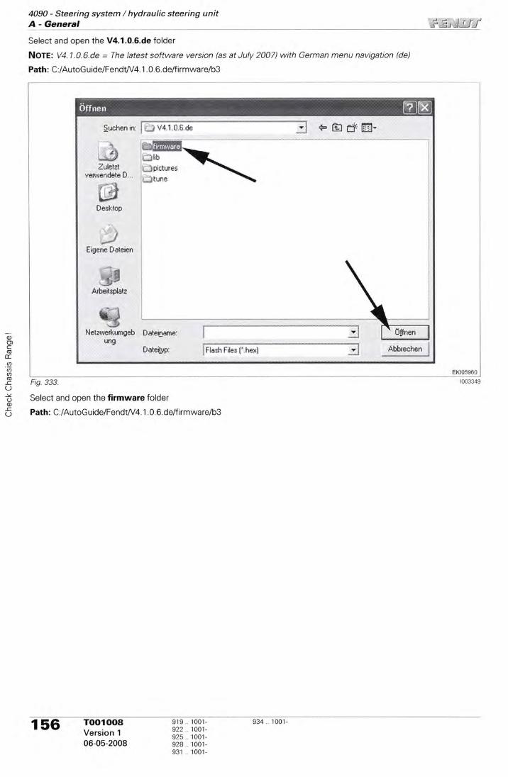
4090 - Steering system / hydraulic steering unitA - General ;irt)rLr
o)o)coE.ID'aa(U-CO-\zooIO
Select and open the V4.1.0.6.de folder
Nore: V4.1.0.6.de = The latest software version (as at July 2007) with German menu navigation (de)
Path: C:/AutoGuide/FendW4. 1 .0.6. de/f irmware/b3
Fig. 333.
Select and open the firmware folder
Path : C :/AutoG u ide/FendW4. 1 . 0. 6. de/f i rmwa relb3
§uchen in: I i;;å V*.t,f.aae1,e-.a§v I qæ lsj ff [iii-
- a^*§ffilq §*;4&6åi*ffit&;d
."*# lhbZrietat __lprctures
verwendeteD... --jtune
1:*:."$L*"*
Besklop
,Jfigen* Dateien
;. _;@
Årb*its$ala
%J-jp
Nelrue&urqe'br81S
*ateiname:
§dei§ry lFbsh File§ {..hæx}
156 I3:tf i 3t! 1331" e34 1oo1
06-05-2008 333 i33l-931 1001-
Sffn*n

$.*:!5J4090 - Steering system / hydraulic steering unit
A - General
* s"Hff m,
Select and open the b3 folder
Path : C :/AutoG u ide/Fe ndW4. 1 . 0. 6. de/f i rmwa relb3
Fig 335
of(Dc)Tl-o)(tU'.U'
1(»l(oq
Fig. 334
Zuletzl Elldsptl0?Bt.he:venqendeteD E,lxilin>rt0i.hex
l' **\-J
0e*top
/Eigene flaleier
.ø'i',#Årbeilspiatz
ffi.åheta,ø*rkumg*b $aleisarna:
Uf,g
0atei§pr
ffiffi.-§ bsac*;gr*-r+,0. 1,?.he«
j 4,&fyEB-
Reihenfolge beachten !
1. 2303"hex2. dsp110281"hex3. xilinx103.hex4. bsac_agco*v4.0. 1 .7.hex
§uclrån;n: i # b3
fFtasn rau" f.ttext }
919 1001-922 ..1001-925 . 1001-928. 1001-931 ..1001-
TOO100aVersion 1
06-05-2008
157
iisx*n

4090 - Steering system / hydraulic steering unitA - General
JJ t--)J-l,t )lJJ
oo)C(UE.a'aa(§-cOIZoo
-CO
The data sets are displayed
Nore: Ihe data sets must be loaded onto the /.058 Auto-Guide1. 2303.hex2. dspl 10281 .hex3. xilinxl03.hex4. bsac_agco_v4. 0. 1 . 7. hex
Select and open the first data set (2303.hex)
Fig 336
Click Flash
The software is now loaded onto the 4058 Auto-Guide TopDock
TopDock in a predefined sequence!
158 934 1001-TOO1()()8Version 1
06-05-2008
919 100',t-922 ..'tOO't-925..1001-928.. 1001-931 ..1001-

::t !t I i4090 - Steering system / hydraulic steering unit
A - General
Fig. 337 loo3352
Press OK to continue
Switch the Auto-Guide standby switch off and on again within 15 seconds (resetting the A058 Auto-Guide Top-Dock)
Switch the A058 Auto-Guide TopDock off and on againwithin 15 seconds
Press the standby switch (B) for approx, 5 seconds(LED off) = A058 Auto-Guide TopDock off
Press the standby switch (B) (LED flashing) = A058Auto-Guide TopDock on
Fig. 338.
of(DoT
foU)(r.(,a(»f(oq
elb\elffi ffi-Æ{\ -\-is++*\-**:ft
olo
922925924931
1001-1001-1001-1001-1001-
TOO100aVersion 1
06-05-2008
934.. 1001- 159

4090 - Steering system / hydraulic steering unitA - General
0)o)C(Ucca'aU'(§
_cOlzoo-CO
The red LED is lit = A058 Auto-Guide TopDock is ener-gisedThe red LED is off = 4058 Auto-Guide TopDock is not en-
ergised.
Fig 220
Fiq.340.
lf the data set has been programmed successfully, the following message will appear: FIash firmware complete
TOO1008Version 1
06-05-2008
919922925928931
1 00'1-1001-100'1-100'1-1001-
160 934. 1001-
{§,&tto"&uite§srvir*i..rat Ll" §}4i
gle (*nfiqure [tlp
ffisp*tlJrtlHløgt*ø&. &t 1*g l4arxar*

)-)-F)
r:l llJI4090 - Steering system / hydraulic steering unit
A - General
Fig. 341
Follow the same procedure for the other 3 data sets in the correct sequence
C)=rooxf-oaaØllo)l(og
919922925924931
1001-1001-1001-1001-1001-
TOO1008Version 1
06-05-2008
161

4090 - Steering system / hydraulic steering unitA - General iir)rri
6O)c(u
ccØ'(tao-c(J-vo(l)
162 l:.:tf i 3t! 1331. e34 1001.
06-05-2008 333 1331-931 ..1001-

-F=!:4090 - Steering system / hydraulic steering unit
Table of contents
,l
2?
45
6
B Faults
Auto-Guide-errorcodetable . ..165Auto-Guide system: Offset cross track ('AUTO-OFFSET') . . . . jg2Reading Auto-Guide system information "Details" . . . . .194Checking the satellite reception by the Auto-Guide system . .202Checking Auto-Guide (range: hydraulic steering) with AO59-Auto-Guide terminal . . . . . .2OgSetting the frequency and channel of the radio module (tractor and base station) . . . . . .212
C)foTC)foaa.(taof
q
919 r001-922 1001-92s 'r001-
928 .1001-931 . 1001-
934 1001- 163

4090 - Steering system / hydraulic steering unitTable of contents ;\ ;),, )1;1i
oc§E..aU'U)(oEO-v.oo(-)
16,4 1001-1001-1001-1001-1001-
919922925928931

I . i ,ti'l 11..i l
4090 - Steering system / hydraulic steering unitB - Faults
Auto-Guide - error code table
Warning and fault messagesThe 4059 Auto-Guide terminal has two types of error messages:
Warning messagesWarning messages are information messages that inform of changes to the Auto-Guide system.
Fault messageA fault message points out an event that disengages the automatic steering ("Steering Assist"), the driver must again as-sume manual control of the tractor.
Confirm the warning and fault messages with OK
Reading the error memory on the A059 Auto-Guide terminal ("system log")The "system log" displays Auto.Guide error messages.
lgnition ON,The 4059 Auto-Guide terminal starts up (takes approx. 2minutes)
Confirm warning message (DISCLAIMER) by pressingoK.
Fig. 2.
'}*5*
Warning and fault messages
System reports (fault in the satellite reception and analysis):These messages come from the A058 Auto-Guide TopDock (receiver unit)
Terminal reports (fault in the operation):These messages come from the A059 Auto-Guide terminal
VIU reports (fault in the steering system):These reports come from the A050 ECU, basic control unitNote: The defects (Code V) are also displayed on the 4007 instrument panel
925924ora931931
919919922922925
0101-1 0001001-0101-1 0001001-01 01 -1 000
100r-01 01-1 0001001-01 01 -1 0001001-
oat
93401 0 r-1 0001 001-
TOOOa2TVersion 2
06-05-2008
165
MM
ry.6t
Fig. 1.
Code 8....
Code T ----
Gode V ....
PrtS:T{i}-
*{t
&&,&*
*sAtra iå\

4090 - Steering system / hydraulic steering unitB - Faults ':lt I I l I
Scroll with the arrow key
Switch to the status indicator with the measuringgauges
The "Status" screen is displayed.
This page displays the status of the Auto-Guide com-ponents.
A green tick means that the component is
operational.
A red cross means that the component is
not operational.
DMU = electronic gyro compass (in the 4058 TopDock)Correction = Correction signal receptionGPS = ECU, GPS (electronic box in the 4058 TopDock)Steer = A050 ECU, basic control unitComms = Connection between Auto.Guide components Fig S'
- From the "Status" screen, press the System Log but-ton
166 TOOOa2TVersion 2
06-05-2008
01 01-1 0001 00101 01-1 0001001-0101 1 000
1001-01 01-1 0001001-01 01-1 000'I 001-
01 01 -1 0001001-
925928928931931
919919922922925
934934
Fig. 3.
reffinffidffi&ffiI .: :: :::::::.*,&wffi
ffi ffikil
Fig. 4.
l'.i a ,tG
ffi::".{

i ], J r,-f4090 - Steering system / hydraulic steering unit
B - Faults
Press the arrow keys to read lengthy errormessages
Press Update to update the error mes-sages
Fig. 7.
System messages from 4058 Auto-Guide TopDock (receiver unit)
A058 Auto-Guide Top-DockFault
Disconnect and reconnect the X1633 separation point on 4058 Auto-Guide TopDock
Call up the "Details" on the "Status" screen to view the current operat-ing statuses
A058 Auto-Guide TopDock:DMU (gyro compass)Vertical acceleration is toohish
Disconnect and reconnect the X1633 separation point on 4058 AutoGuide TopDock
Call up the "Details" on the "Status" screen to view the current operat-ing statuses
A058 Auto-Guide Top-Dock:DMU (gyro compass)Vertical acceleration is toolow
Disconnect and reconnect the X1633 separation point on the Auto-Guide TopDock
Call up the "Details" on the "Status" screen to view the current operat-ing statuses
A058 Auto-Guide Top-Dock:DMU (gyro compass)The vertical accelerationsensor is not calibrated.
- Calibrate roll bias (carry out calibration using HPiRTK correction signal)
HP = OmniStar correction signalRTK = correction signal from the base station
A058 Auto-Guide Top-Dock:DMU (gyro compass)The yaw sensor is abovethe normal operatingrange (yaw = revolving onthe vehicle's vertical axis)
Disconnect and reconnect the Xl633 separation point on the Auto-Guide TopDock
Call up the "Details" on the "Status" screen to view the current operat-ing statuses
4058 Auto-Guide TopDock:DMU (gyro compass)The yaw sensor is belowthe normal operatingrange (yaw = revolving onthe vehicle's vertical axis)
Disconnect and reconnect the X1633 separation point on the Auto-Guide TopDock
Call up the "Details" on the "Status, screen to view the current operat-ing statuses
A058 Auto-Guide Top-Dock:DMU (gyro compass)The yaw sensor is abovethe normal yaw rate whenvehicle is stationary (yaw
= revolving on the vehi-cle's vertical axis)
Disconnect and reconnect the X1633 separation point on the Auto-Guide TopDock
Call up the "Details" on the "Status" screen to view the current operat-ing statuses
919919922922925
01 01-1 0001001-01 01-1 0001001-01 01-1 000
925..1001-928..0101-1000928 1 001-931 0101-1000931 1 001-
01 01-10001 001-
934934 I,:råru 167
06-05-2008
B 0012
B 0100
B 0101
80113
B 0200
B 0201
B 0210

B 0211 A(E8 Auto-Guide Top-Dock:DMU (gyro compass)The yaw sensor is belowthe normal yaw rate whenvehicle is stationary (yaw
= revolving on the vehr-cle's vertical axis)
Disconnect and reconnect the X1633 separation point on the Auto-Guide TopDock
Call up the "Details" on the "Status" screen to view the current operat-ing statuses
B 0213 A058 Auto-Guide Top-Dock:DMU (gyro compass)The yaw acceleration sen-sor is not calibrated.
- Calibrate roll bias (carry out calibration using HP/RTK correction signal)
HP = OmniStar correction signalRTK = correction signal from the base station
B 0301 A058 Anto-Guide Top-DockVoltage supply below mini-mum voltage of 70 VDC
Check voltage supply:- Check F22 fuse- Check A050 ECU, basic control unit (activation signal for 4058 Auto.GuideTopDock)
B 0500 A058 Auto-Guide Top-Dockoverloaded
Disconnect and reconnect the X1633 separation point on the Auto-Guide TopDock
Call up the "Details" on the "Status" screen to view the current operat-ing statuses
B 0605 A058 Auto-Guide Top-Dock:GPS aerialThe electrical circuit of theGPS aerial is open
Disconnect and reconnect the X1633 separation point on the Auto-Guide TopDock
Call up the "Details" on the "Status" screen to view the current operat-ing statuses
B 0606 A058 Auto-Guide Top-Dock:GPS aerialThe electrical circuit of theGPS aerial has a short cir-
cuit to earth
- Disconnect and reconnect the X1633 separation point on the Auto-Guide TopDock
Check cables and connectors
Call up the "Details" on the "Status" screen to view the current operat-ing statuses
B 0609 A058 Auto-Guide Top-Dock:GPS aerialGPS aerial failure
Disconnect and reconnect the Xl633 separation point on the Auto-Guide TopDock
Call up the "Details" on the "Status" screen to view the current operat-ing statuses
B 0700 A058 Auto-Guide:DMU (gyro compass)DMU (gyro compass) tem-perature is above maxi-mum operatingtemperature of 85.0"C
Ensure that DMU temperature does not exceed maximum operatingtemperature
Call up the "Details" on the "Status" screen to view the current operat-ing statuses
B 0701 A058 Auto-Guide Top-Dock:DMU (Syro compass)DMU (gyro compass) tem-perature is below minr-mum operatingtemperature of -45'C
Ensure that DMU temperature does not drop below minimum operat-ing temperature
Call up the "Details" on the "Status'screen to view the current operat-ing statuses
B 0809 A058 Auto-Guide Top-Dock:DMU (gyro compass)The data update rate is notnormal (fewer than 40packets per second)
Call up the "Details" on the "Status" screen and check the "DMU Pack-ets/Sec". The update rate during operation should be between 70 and90 packets per second, reprogram 4058 Auto-Guide TopDock
lf the update rate is below 70 packets per second: Disconnect andreconnect the X1633 separation point on the Auto-Guide TopDock
Check the DMU "gyro compass" connector (Note: See also chapter9000 Reg.E - A058 ECU, Measuring and testing AutoGuide TopDock)
Call up the "Details" on the "Status" screen to view the current operat-ing statuses
4090 - Steering system / hydraulic steering unitB - Faults
,f l^a TOOOa2T 919 0101-1000 925 .. 1001- 934 ..0101-1000r rr(,
Version 2 919.. 1001- 928 0101-1ooo 934 loor-922 0101-1000 928.. 1001-
06-05-2008 s22 looi- s3t ..010'l-1000925 ..0101-1000 931 .. 1001-
@ @u'@ffid

)1, lrf f4090 - Steering system / hydraulic steering unit
B - Faults
B 0812 A(88 Auto-Guide TopDock:DMU (gyro compass)Communication betweenGPS receiver unit andDMU disrupted
Disconnect and reconnect the X1633 separation point on the AutoGuide TopDock
Check the DMU 'gyro compass" connector (Note: See also chapter9000 Reg. E - A058 ECU, Measuring and testing Auto-Guide TopDock)
B 0813 A058 Auto-Guide Top-Dock:DMU (gyro compass)The DMU is not calibrated
Carry out the calibration for the roll bias
B 0900 A058 Auto-Guide TopDockThe temperature of theA058 Auto-Guide TopDock is above the maxi-mum operatingtemperature of 85'C
Ensure that the temperature of the 4058 Auto-Guide TopDock doesnot exceed the maximum operating temperature
B 0901 A058 Auto-Guide Top-DockThe temperature of theA058 Auto-Guide TopDock is below the mini-mum operatingtemperature of -40"C
Ensure that the temperature of the 4058 Auto-Guide TopDock doesnot fall below the minimum operating temperature
B 0902 A058 Auto-Guide Top-DoekThe power supply (+UB30) of the A0SB Auto.Guide TopDock lies abovethe max. voltage of 16 0VDC
Check the G002 alternator 1
Check the G004 alternator 2
B 0903 A058 Auto-Guide Top-Dock:GPS aerialThe GPS aerial or theA058 Auto-Guide ToqDock cannot receive theL1 signal frequency fromthe satellite.
Disconnect and reconnect the X'|633 separation point on the Auto-Guide TopDock
Call up the "Details" on the "Status-screen" to read out the active oper-ating status
B 0904 A058 Auto€uide TopDock:GPS aerialThe GPS aerial or theA058 AutGGuide TopDock cannot receive theL2 signal frequency fromthe satellite.
Disconnect and reconnect the X1633 separation point on the Auto-Guide TopDock
Call up the "Details" on the "Status-screen" to read out the active oper-ating status
B 0905 A058 Auto-Guide Top-Dock:Radio module (receiver)The radio module is notrecognised by the 4058Auto-Guide TopDock
- Disconnect and reconnect the X1633 separation point on the Auto-Guide TopDock
- Check the pins on the radio module
With sporadic occurrence: warning message only
B 1012 Base station:GPS aerialFault in the GPS receiverof the base station
- Unclamp and re-clamp (reset) the power supply to the base station
919,0101-1oOO9r9 1001-922 .0101-1000922 ..1001-925..0101-1000
925..1001-928..0101-1000928 1001-931 0101-1000931 .1001-
01 01 -1 0001001-
TOOO827Version 2
06-05-2008
934o1A 169
Doscription

4090 - Steering system / hydraulic steering unitB - Faults l..t
\ tl I J I
B 1100 Base station:GPS aerialThe GPS aerial tempera-ture is too highTemperature = max.100'c
Ensure that the base station temperature does not exceed the maximumoperating temperature
B 1200 Base station:GPS aeria!The power supply of theGPS aerial lies above themaximum voltage ofapprox. 16.0 VDC
Check the power supply on the base station (specified value: 10 ... '15
VDC)
B 1309 Base station:GPS aerialThe GPS aerial cannotreceive the L1 signal fre-quency from the satellite.
- Unclamp and re-clamp (reset) the power supply to the base station
B 1500 Base station:GPS aerialThe processor (CPU) ofthe GPS aerial (receiverunit) was momentarilyoverloaded
- Unclamp and re-clamp (reset) the power supply to the base station
'er
* Unclamp and rp (reset) the power
or
B 1606 Base station:GPS aerialThe electrical circuit of theGPS aerial has a short cir-
cuit to earth
- Unclamp and re-clamp (reset) the power supply to the base station
,fa,ll Toooa2T 919 0101-1000 925.. 1001- 9s4 0101-1000t , v Version 2 919 1001- 928..0101-1000 934 1001-
922 0101-1000 928 .1001-06-05-2008 s22 looi- e3r .. o1o1-r000
925. 0101-1000 931 .. 1001-
B 1'10't Base station:GPS aerialThe GPS aerial tempera-ture is too lowTemperature = min -40"C
B 1201 Base station:GPS aerialThe power supply of theGPS aerial lies below themin. voltage of approx. 70VDC
Check the power supply on the base station (specified value: 10 ... 15
VDC)
B 1409 Base station:GPS aerialThe GPS aerial cannotreceive the L2 signal fre-quency from the satellite.
- Unclamp and re-clamp (reset) the power supply to the base station
B 1605

-,1,, lrr/4090 - Steering system / hydraulic steering unit
B - Faults
- Unclamp and re-clamp (reset) the power supply to the base station
For WAAS correction signal: Tractor must have a clear view of the sky.
- Check on the A059 Auto-Guide terminal whether the signal strengthdisplay shows at least 3 bars. lf fewer than 3 bars are displayed, waituntil the signal strength increases
For OmniStar VBS/OmniStar HP: Check whether the correction signallicense has expired. - Check on the 4059 Auto-Guide terminalwhether the signal strength display shows at least 3 bars. lf fewerthan 3 bars are displayed, wait until the signal strength increases
For RT20 or RT2 accuracy position: communication problem with thebase station. Check whether the local base station is functioning cor-rectly. The tractor must have a clear view of the local base station. -Check on the 4059 Auto-Guide terminal whether the signal strengthdisplay shows at least 3 bars. lf fewer than 3 bars are displayed, waituntil the signal strength increases. - Drive nearer to the local basestation; if this solves the problem, the tractor was outside the range ofthe local base station.
Base station:GPS aerialCorrection signal is erratic,intermittent or wrong
I nvalid authorisation code
System messages from the 4059 Auto-Guide terminal
lnternal fault, appearedwhen loading the problemreport file
- Switch ignition off and on (reset)
Fault when adjusting thesubmenu "set waypoints Aand B"
- Switch ignition off and on (reset)
Fault when adjusting thesub-menu "set waypointsA and B"
Switch ignition off and on (reset)
- Switch ignition off and on (reset)
r 0303 Waypoint cannot be set Check the signal strength. At least 3 bars must be displayed. lf fewerbars are displayed, wait until the signal strength increases.
The min. distance between waypoint A and waypoint B must be 10 m
First set waypoint A
Check the Auto-Guide standby switch (4039 multifunction armrestMFA)
Check the correction signal license
The connection betweenthe 4059 Auto-Guide ter-minal and the 4058 Auto-Guide TopDock is inter-rupted.Auto-Guide operation isnot possible
Switch ignition off and on (reset)
Check the wiring set and connector between 4059 Auto-Guide termi-nal and the 4058 Auto-Guide TopDock
Defect when setting thewaypointlncorrect status
Switch ignition off and on (reset)
Waypoints cannot be setas the automatic trackguide is active.
- Switch off the automatic track guide
s1s oror-ro-oo919..1001-922..010r-1000922 ..1001-925..0101-1000
1001-01 01 -1 0001001-0101-1 0001001-
01 01 -1 0001 001-
TOOOaZTVersion 2
06-05-2008
ort924928931931
934934 171
*trffiHffii%
B 1609 Base station:GPS aerialGPS aerial failure
B 3202
o aala Check authorisation code
T 0101
T 0300
T 0301
T 0302 Fault when setting thewaypoint
T 0304
T 0305
T 0306

4090 - Steering system / hydraulic steering unitB - Faults i' :r. )tri
T 0307 Field memory (savingagricultural fields)The maximum memorycapacity of the 4059 Auto-Guide terminal has beenreached
Delete fields that are no longer needed; see Auto-Guide operatingmanual
T 0308 Field memory (savingagricultural fields)Approaching the maxi-mum memory capacity ofthe A059 Auto-Guide ter-minal
Delete fields that are no longer needed; see Auto-Guide operatingmanual
lf the maximum memory capacity is reached, fault T 0307 is displayed
T 0500 Fault when calling up the4058 Auto-Guide Top-Dock status
- Switch ignition off and on (reset)
T 0501 Fault when calling up the4058 Auto-Guide Top-Dock status (internal codeerror)
- Switch ignition off and on (reset)
T 0502 The 4058 Auto-Guide Top-Dock has established a
connection to the con-nected components
- Display only (no fault)
T 0503 The 4058 AutoGuide Top-Dock has not establisheda connectron to the con-nected components
Check the wiring and connectors between the A059 Auto-Guide termi-nal and the 4058 AutoGuide TopDock
Check the Auto-Guide standby switch (4039 multifunction armrestMFA}
Disconnect and reconnect the X1633 separation point on the Auto-Guide TopDock
T 0600 Signal strength cannot bedisplayed
Check the correction signal
T 0601 Track positioning cannotbe displayed
Check the correction signal
T 0602 Signal strength cannot bereceived
Check the correction signal
T 0603 Track positioning cannotbe received
Check the correction signal
T 0700 lnternal fault when adiust-ing the implement width
Switch ignition off and on (reset)
Restart the implement width
T 0701 Implement width cannotbe adjusted. A connectionbetween the 4059 Auto-Guide terminal and the4058 Auto-Guide Top-Dock cannot be estab-lished
Check the wiring and connectors be&veen the A059 Auto-Guide termi-nal and the 4058 Auto.Guide TopDock
Check the Auto-Guide standby switch {4039 multifunction armrestMFA)
Disconnect and reconnect the X1633 separation point on the Auto-Guide TopDock
r 0702 lmplement width limit notset within 0.001 and 2540metres
Ensure that the implement width limit has not been set to 0, and is within0.001 and 2540 metres
T 0703 lmplement width limit notset within 0.1 and99,999"9 inches
Ensure that the implement width limit has not been set to 0, and is within0.1 and 99.999 I inches
T 0704 lmplement offset not setwithin 0 and 2450 metres
Ensure that the implement offset is within 0 and 2450 metres
4a, TOOOa2T 919 0101-1000 925.. 1001- 934..0101-1000. , tz 919.. 1001- 928..0101-1000 934.. 1001-version 2 n22 010r-1000 928.. 1001-06-05-2008 s22 1oo1- e31 0101-1000
925 0101-1000 931 ..1001-

4090 - Steering system / hydraulic steering unitB - Faults
T 0705 lmplement offset not setwrthin 0.'l and 99,999,9inches
Ensure that the implement offset lies within 0.1 and 99,999.9 inches
T 0706 No directron (left or right)is set for the implementoffset
Set the direction for the implement offset on the Auto-Guide terminal
I 0707 The direction has been setfor the implement offset,the implement offset limithas not been entered
Enter an implement offset limit (metres or inches) on the Auto-Guide ter-minal
T 0708 lmplement memoryThe maximum memorycapacity of the A059 Auto-Guide terminal has beenreached
Delete implements that are no longer needed; see Auto-Guide operat-ing manual
T 0709 lmplement memoryApproaching the maxr-mum memory capacity ofthe 4059 Auto-Guide ter-minal
Delete implements that are no longer needed; see Auto-Guide operat-ing manual
lf the maximum memory capacity is reached, fault T 0708 is displayed
T 0710 The automatic track guidedoes not switch on as noimplement has beenentered
Enter implement
T 0711 lmplement link lengthof 0 and 327 m exceeded
Link length =distance f rom three-pointrear power liftto thework area of the imple-mentThrs entry is needed whena contour or circle isretraced
Ensure that the implement link length is set between 0 and 327 metres
T 0712 lmplement link lengthEnsure that the implementlink length is set between0 and 12,900 inchesLink length =distance f rom three-pointrear power liftto thework area of the imple-mentThis entry is needed whena contour or circle isretraced
Ensure that the implement link length is set between 0 and 12,900 inches
T 0800 lnternal error when settingthe wayline offset
Switch ignition off and on (reset)
Re-enter the wayline offset
T 0801 Wayline offset cannot beadjusted The connectionbetween the 4059 Auto-Guide terminal and the4058 Auto-Guide TopDock is interrupted
Check the wiring and connectors between the A059 Auto-Guide termi-nal and the A058 Auto-Guide TopDock
Check the Auto-Guide standby switch (4039 multifunction armrestMFA)
Disconnect and reconnect the X1633 separation point on the Auto-Guide TopDock
919 0101-1000 925 . 1001- 934 0101-1000 TOOOa2T 4 a1'919 1001- 928..0101-1000 934 . 1001-922 0101-1000 928 1001-
1001- Version 2 ' ' 's22. 1001- 931 o1o1-looo 06-05-2008925..0101-1000 931 . 1001-
Descdption §emsdy

4090 - Steering system / hydraulic steering unitB - Faults
T 0802 lnternal error when settingthe wayline offset lnvalidoffset
Switch ignition off and on (reset)
Be-enter the wayline offset
T 0803 The wayline offset wasselected, but not the offset direction
Set the wayline offset direction
T 0804 The wayline offset direc-tion was selected, but notthe offset value
Set the wayline offset
T 0805 The wayline offset value is
not within the set limits,appears only when metricunits are set
Ensure that the offset value is set within the limits (0 to 2540 metres)
T 0806 The automatic wayline off-set cannot be calculatedwhen no implement widthis set
Set the implement width
T 0807 The automatic wayline off-set cannot be calculatedwhen no waypoints areset
Set waypoints A and B
T 0808 The automatic wayline o{f-set cannot be calculatedwhen neither the way-points nor the implementwidth is set
Set the implement width and the waypoints A and B
T 0809 Track line offset outsidepermissible range.The valid range is between0 and 12,900 inches
Set new waypoints A and B
T 0810 The real-time track line off-set is outside the permis-sible range.The valid range is between0 and 10 metres
Set new waypoints A and B
T 0811 The real-time track line off-set is outside the permis-sible range.The valid range is beilveen0 and 400 inches
Set new waypoints A and B
T 0812 The total track line offsetis outside the permissiblerange.The valid range is between0 and 327 metres
Set new waypoints A and B
T 0813 The total track line offsetis outside the permissiblerange.The valid range is between0 and 12,900 inches
Set new waypoints A and B
T 0900 Connection to the 4058Auto-Guide TopDock isinterruptedlnternal code error on the4058 AutoGuide TopDock
Switch the Auto-Guide standby switch off and on againStandby switch off = LED off
174 roooa2T 313 ?å31-"" 333 å?3l.,ooo 33X ?å31-''ooVersion 2 n22..o101-iooo 928.. 100r-
06-05-2008 s22 1oo1- e31 0101-1000925 01 01-1 000 931 1 001-

i,.,, r lli i
4090 - Steering system / hydraulic steering unitB - Faults
T 1000 Connection to the A058Auto-Guide TopDock isinterruptedlnternal code error on the4058 Auto-Guide TopDock
Switch the Auto-Guide standby switch off and on againStandby switch off = LED off
T 1001 Warning message:This process is not possi-ble while the field calcula-tion is in progress.
Restart the process
T 1002 Warning message:The accuracy has beendowngraded to RT 20The repetition accuracycannot be guaranteed.
Confirm warning message with OK to return to map vrew
T 1100 Connection to the 4058Auto.Guide TopDock is
interruptedlnternal code error on the4058 Auto-Guide TopDock
Switch the Auto-Guide standby switch off and on againStandby switch off = LED off
T 1101 Fault in the 4059 Auto-Guide terminal whenadlusting the steeringresponse.The 4058 Auto-Guide Top-Dock does not respond.
lf this error occurs, the steering response on the 4059 Auto-Guide terminalis set to the middle value
T 1102 Fault in reading the steer-ing response setting.Reading error.
lf this error occurs, the steering response is set to the middle value
T 1200 Fault in reading the unit ofmeasurement. Readingerror.
lf this error occurs, measurement units are set to metric.
T 1201 Fault occurred while set-ting measurement units.The 4058 Auto-Guide Top-Dock does not respond.
Check the wiring set and connector between A059 Auto-Guide termi-nal and the A058 Auto-Guide TopDock
Check the Auto-Guide standby switch (A039 multifunction armrestMFA)
T 1202 Warning messageAll values invalid if unit ofmeasurement is changed.It is not possible to enableautomatic track guidancewithout specifying theworking width.
Press OK to continue.Press ESC to cancel.
T 1300 Fault in calibratrng the8067 steering angle sen-sorThe 4058 Auto-Guide Top-Dock does not respond.Note: See also chapter0000 Reg.F -Calibration code 2401(steering angle sensor)
Check the wiring set and connector between A059 Auto-Guide termi-nal and the 4058 Auto-Guide TopDock
Engine is running, switch on the Auto-Guide standby switch (LED on)
Check the X1403 separation point on the 4050 ECU, basic control unit
T 1301 The B067 steering anglesensor cannot be calr-brated as long as the auto-matic track guide is activeon the 4059 Auto-Guideterminal
Switch off the automatic track guide on the 4059 Auto-Guide terminal
Engine is running, switch on the Auto.Guide standby switch (LED on)
Check the wiring set and connector between 4059 Auto-Guide termi-nal and the 4058 Auto-Guide TopDock
Check the X1403 separation point on the 4050 ECU, basic control unit
91L919 .
922922.925
01 01-1 0001001-0101-'10001001-01 01-1 000
1001-0101-10001001-01 01 -1 000'I 001-
01 01 -1 0001 001-
925928928931931
934934 I,:ffir, 175
06-05-2008

4090 - Steering system / hydraulic steering unitB - Faults §j.li5/
T 1302 The driver attempts toswitch on the automatictrack guide while the B067steering angle sensor is
being calibrated
Do not switch on the automatic steering system ("Steering Assist") untilthe 8067 steering angle sensor ca[bration is completed.
T 1303 Tractor in forward opera-tionThe automatic track guidedoes not engage whenthe speed is above 25kmih
Reduce vehicle speed
T 1304 Tractor in forward opera-tionThe automatic track guidedoes not engage whenthe speed is above 25km/h
Reduce vehicle speed.
T 1305 Tractor in reverse opera-tionThe automatic track guidedoes not engage whenthe speed is above 25km/h
Reduce vehicle speed.
T 1306 Tractor in reverse opera-tionThe automatic track guidedoes not engage whenthe speed is above 25km/h
Reduce vehicle speed.
T 1500 Fault in the adjustment ofthe correction signal
Check the wiring set and connector between 4059 Auto-Guide termr-nal and the A058 AutoGuide TopDock
Check the X1403 separation point on the 4050 ECU, basic control unit
T 1501 Fault in the read-out of thecorrection signal from the4059 AutoGuide term inal
lf this error occurs, the WAAS correction signal is adjusted in the 4059Auto-Guide terminal
r 1502 Warning:The base station type can-not be selected.
Check communication
T 1503 Warning:The previous base stationtype cannot be re-selected.
T 1504 Warning:Tower mode cannot beselected
Check communication
T 1505 Warning:The previous tower modecannot be re-selected.
T 1506 This information is notavailable for the correctionsignal selected
Press OK to continue
T 1507 Warning:This information is notavailable for the correctionsignal selected
ia,|, Toooa2T 919..0101-1000 925 1001- 934 0101-1000.,v Version 2 919..100r- 928 0101-1000 934 i001-
922..0101-1000 928. 1001-06-05-2008 s22 .. too1- e31 0101-1000
925..0101-1000 931 1001-
-:_

i ir )JlJ4090 - Steering system / hydraulic steering unit
B - Faults
T 1508 The correction signal can-not be changed if auto-matic track guidance is
enabled.
Swrtch off automatic track guidance to continue.
T 1700 Automatic track guidancehas been switched offunexpectedly.
Switch automatic track guidance back on
T 1701 Too large a drstance to thewayline during automatictrack guidance
Reduce distance
T 1800 Fault in the test of thesteering system with theaid of the 4059 Auto-Guide terminal
Fault occurred upon man-ual activation of the steer-ing
Auto-Guide system {reset)- Switch off the ignition and unplug the X'1633 separation point on the
Auto-Guide TopDock
- Plug in the X1633 separation point on the Auto-Guide TopDock andswitch on the ignition
T 1801 Fault in the test of thesteering system with theaid of the 4059 Auto-Guide terminalThe automatic track guideis active.
Switch off the automatic track guide
T 1802 The driver attempts toswitch on the automatictrack guide while thesteering test is running
Do not switch on the automatic track guide until the steering test is com-pleted
T 1803 Safety message that is
displayed on the 4059Auto-Guide terminalbefore the steering test.
Follow the instructions displayed
T 1804 The steering test cannotbe carried out as long asthe tractor is in motion
Bring the tractor to a standstill
T 1900 Fault when setting theregion (Europe, NorthAmerica etc.), internalcode error
- Switch ignition off and on (reset)
T 1901 Fault when setting theregion (Europe, NorthAmerica etc.), check theconnection between the4058 Auto-Guide TogDock und the 4059 Auto-Guide terminal
Check the wiring and connectors between the 4059 Auto-Guide terminaland the A058 Auto-Guide TopDock
T 2000 The day and night modecannot be switched overwhile the automatic trackguide is engaged
Switch off the automatic track guide on the 4059 Auto-Guide terminal(Note: A signal tone shows that the automatic track guide has beenswitched off); switch between day and night mode
T 2100 The tractor type must bespecified
Specify tractor type
T 2101 Call up tractor type Select tractor typeorPress ESC to cancel
r vo2 The tractor type enteredalready exists
Specify new tractor type
919..0101-1000919..',I001-922..0101-1000922. 1001-925 0r01-1000
1001-01 01 -1 0001001-01 01 -1 0001001-
01 01 -1 0001 001-
934934
925924928931931
TOOOaZTVersion 2
06-05-2008
177
Remedy

4090 - Steering system / hydraulic steering unitB - Faults
J J I --, J
J tt )lJJ
T 2200 No implement name wasspecif ied
Specify an implement name and confirm with "Enter
T 2201 The entry for the imple-ment name was not con-firmed
Confirm the implement name with "Enter"
r 2202 The implement namespecif ied already exists
Change the implement name
T 2203 The implement width can-not be accessedNo communicationbetween the 4059 Auto-Guide terminal and theA058 Auto-Guide TopDock
Confirm the message and re-confirm the implement width
Switch ignition off and on (reset)
T 2204 The width of the imple-ment cannot be importedas this has been storedunder a dlfferent unit ofmeasurement.
Change unit of measurement
T 2300 The field name was notspecified
Specify the field name and confirm with "Enter"
T 2301 The field name was notconfirmed
Confirm the field name with "Enter"
T 2302 The field name cannot beaccessedNo communicationbetween the 4059 Auto-Guide terminal and the4058 Auto-Guide TopDock
Confirm the message and re-access the field name
Switch ignition off and on (reset)
T 2303 The field name alreadyexists
Change the field name
r 2304 The field name cannot beaccessed as the automatictrack guide is active
- Switch off the automatic track guide
T 2305 The field was processedwith another signal (base
station and correction sig-nal).
Follow the display on the 4059 Auto-Guide terminal
T 2306 The field was processedwith another correctionsignal.
- Follow the display on the 4059 Auto-Guide terminal
r 2307 The field was processedwith another base station.
Follow the display on the 4059 Auto-Guide terminal
T 2308 The field surface cannotbe called up as long as thewayline calculation is inprogress
Allow wayline calculation to complete and re-start process
T 2309 CautionThe max. speed (km/h) forcontour and circle trackguidance is limited.High speeds can lead todangerous driving situa-tions
Press OK to continue
l aQ TOOOa2T 919 .. 0101-1000 925 . 1001- 934 .. 0101-1000t ,1t,
Version 2 9r9..1001- 928 0ro1-1ooo 934 1oo1-922..0101-1000 928 1001-
06-05-2008 s22 1oo1- e31 . 0101-1000925..0101-1000 931 .. 1001-

i j,' )-tJJ4090 - Steering system / hydraulic steering unit
B - Faulb
T 2310 CautionThe max. speed (mph) forcontour and circle trackguidance is limitedHigh speeds can lead todangerous driving situa-tions
Press OK to continue
T 2311 The field surface databaseis updated and the f ield listis not sorted or filtered in
the process
Press OK to continue
T 2400 The name entered alreadyexists
Delete existing name or change name
T 2401 The selected name is cur-rently active
- Change the name
1 2402 The data card is not recog-nised
Ensure that the data card is correctly inserted
T 2403 The selected name is cur-rently active
- Change the name
T 2404 The selected name is cur-rently active
- Change the name
r 2405 The selected name cannotbe usedThe memory capacity hasbeen reached
- Change the name
T 2406 The selected name isreserved
- Change the name
T 2407 The implements cannot beused.The memory capacity hasbeen reached
- Delete unneeded implements
T 2408 Warning message:Do you wish to delete all
selected itemsT
- Follow the display on the 4059 Auto-Guide terminal
r 2409 Warning message - Follow the display on the 4059 Auto.Gurde terminal
r 2410 Warning message - Follow the display on the A059 Auto.Guide terminal
T 2411 More than one item wasselected.Please select only oneitem.
Press OK to return to the previous screen
r 2500 Data logging not possiblewhile data card notinserted.
lnsert a data card to continue.
T 2501 Data card has beenremoved
lnsert a data card to continue.
T 2502 Data card was detectedData logging enabled
Press 0K to continue
r 2503 Data card full lnsert a new data card or create space on existing card
Press OK to continue
T 2504 Data card error lnsert data card again
Try a new data card
Press OK to continue
919919922922925
01 01 -1 0001001-0101-1 0001001-0101-1 000
1001-01 01 -1 0001001-01 01 -1 0001001-
01 01 -1 0001001-
TOOOa2TVersion 2
06-05-2008
925924ora931931
934934 179
§*seitptian Remedy

4090 - Steering system / hydraulic steering unitB - Faults J J l;i )].ls )-lJJ
T 2600 The 4058 Auto-Guide Top-Dock does not respondwhen asked for the autho.risation code
Check the wiring and connectors between the A059 Auto-Guide termi-nal and the A058 Auto.Guide TopDock
Disconnect and reconnect the Xl633 separation point on the Auto-Guide TopDock
T 2601 An error occurred with theauthorisation coderequest, rendering thesystem inoperable (only
with local base station)
Re-program the Auto.Guide system (please see Auto-Guide program-ming)
lf applicable, read out the serial number of the 4058 Auto-Guide Top-Dock and ask FENDT customer service (Tel.: +49 (01 8342/77-123 arFax: +49 (Ol 8342177-222\ for the authorisation code.
T 2602 An error occurred whilesetti ng a uthorisation code.The 4058 AutoGuide Top-Dock does not respond(with local base stationonly)
Check the connection of the 4059 Auto-Guide terminal to the 4058Auto-Guide TopDock
lf applicable, reprogram the Auto-Guide system (please see: Auto-Guide programming)
T 2603 An error occurred whilesetting authorisation code.No communicationbetween the A059 Auto-Guide terminal and A058Auto-Guide TopDock (withlocal base station only)
Check the connection of the A059 Auto-Guide terminal to the A058Auto-Guide TopDock
lf applicable, reprogram the Auto-Guide system (please see: Auto-Guide programming)
r 2604 lnvalid authorisation code Ensure that you have the correct authorisation code. Re-enter theauthorisation code
lf applicable, read out the serial number of the A058 Auto-Guide Top-Dock and ask FENDT customer service (Tel.: +49 (01 8342177-123 orFax: +49 (01 8342177-2221 for the authorisation code.
T 2605 lnvalid authorisation code Ensure that you have the correct authorisation code. Re-enter theauthorisation code
lf applicable, read out the serial number of the 4058 Auto-Guide Top-Dock and ask FENDT customer service (Tel.: +49 (01 8342177-123 orFax: +49 (01 8342t77-2221 tor the authorisatton code
T 2606 lnvalid authorisation code Ensure that you have the correct authorisation code. Re-enter theauthorisation code
lf applicable, read out the serial number of the ECU, GPS "TopDock'
and ask FENDT customer service (Tel.: +49 (0\ 8342177-123 or Fax:
+49 (0) 8342177-2221for the authorisation code.
T 2607 Warning message:The entry of an invalidauthorisation code causesthe Auto-Guide system toswitch off (Auto-Guide canno longer be used)
Use a valid authorisation code
T 2608 The 4058 AutoGuide Top-Dock is not authorised forthe selected correctionsignal
Press OK to continue.Order correction signal if required and enter authorisation code
r 2700 The travel direction button"cycle button" was pushedwhile the tractor was mov-ing (The tractor must bestationary before the oper-ating direction can beswitched.)
Stop the tractor. Press the travel direction button "cycle-button" (No)
{ Qal Toooa2T 919 0101-1000 e25.. 100',1- 9s4 0101-1000r t tl,
Version 2 919 1001- 928..0101-1000 934 1001-922 0101-1000 928.. 1001-
06-05-2008 s22 tool- s31 ..010r-1000925.. 0101-1000 931 .. 1001-

- J l, r I: \i l: J !
4090 - Steering system / hydraulic steering unitB - Faults
r 2701 Fault when switching theoperating direction The4058 Auto-Guide ToqDock does not respond.
Check the wiring and connectors between the A059 Auto.Guide termi-nal and the 4058 Auto-Guide TopDock
Disconnect and reconnect the X1633 separation point on the Auto-Guide TopDock
T 2800 The data card wasremoved during the saveoperation.Not all data was trans-ferred.
Repeat saving operation
T 2801 The data card wasremoved during the read-ing operation.Not all data was read
Repeat reading operation
T 2802 The data card is fullNo data can be exported
- lnsert new data card or delete data
T 2803 No item was selected.Please select an item
Press OK to continue
T 2900 Fault during discovery oflocal base station (internalcode error)
Re-program the Auto-Guide system (see also: Auto-Guide programming)
T 2901 Contact could not bemade with the local basestation. Check the com-munication between 4058Auto.Guide TopDock andbase station
Disconnect and reconnect the X1633 separation point on the Auto.Guide TopDock
Check the connection of 4058 Auto-Guide TopDock to the base sta-tion.
r 2902 The 4058 AutoGuide Top-Dock remains in "discoverymode"
Switch on the local base station
T 2903 When working with thelocal base station: The cur-rent correction signalsource is not adjusted tothe "local base station"
When working with the local base station: Enterthe local base station ascorrection source
T 2904 The name of the localbase station is not speci-f ied
* Specify name
T 2905 The network name is notspecified
- Specify name
T 2906 One or more settings areinvalid
- Check the settings
T 2907 The network name alreadyexists
- Change name
T 29OB Warning messageThrough this action, theposition determination ofthe base station will beswitched off
* Follow the display on the A059 Auto-Guide terminal
T 2909 Warning messageThe base station must beswitched off and on again(Reset)
Follow the display on the 4059 Auto-Guide terminal
T 2910 The radio module wasbriefly not recognised.Changes may possibly notbe carried out
Check the wiring set
919 0101-1000 925 .. 1001- 934 0101-1000 TOOOA2T I Q I919 1001- 928..0101-1000 934 1001- I (' I922 .. oro1-1ooo gza 1oo1- verslon 2sz?..1oo1- 931 . 0101-1000 06-05-2008925..0101-1000 931..1001-
,...==:.;,."i, i:i

4090 - Steering system / hydraulic steering unitB - Faults fJl-r)
J:7-t l-!J-l
r 2911 Fault in the communica-tion between the base sta-tion and the 4058 Auto-Guide TopDock.
Repeat process, once communication has been re-established.
1 2912 The automatic track guideis currently switched on.Changes are not taken intoaccount as long as theautomatic track guideremains switched on.
- Switch off the automatic track guide
T 2913 The network requesteddoes not exist
Select a different network
T 2914 This action is not possiblewith the radio moduletype selected
T 2915 The channel is outside thepermissible range.The valid range is between-40 and 40
Select a different radio channel
r 2916 The channel cannot be set Check connection to radio module
T 3000 The OmniStar settingsscreen was called upalthough neither Omni-Star VBS nor OmniStar HPis entered as the correc-tion source.
Set OmniStar VBS or OmniStar HP as the correction signal
T 3100 Warning message:Distance to an obstacle(e.9. headland) is outsideof the setting range.Setting range 1 ... 50metres
Enter a distance between 1 and 50 metres
T 3101 Warning message:Distance to an obstacle(e.9. headland) is outsideof the setting range.Adjustment range 36 ...
12,700 inches
- Enter a distance between 36 and 12,700 inches
T 3102 The distance entered is
outside the permissiblerange.The valid range is between0.01 and 5 metres
Enter valid distance
T 3103 The distance entered is
outside the permissiblerange.The valid range is between0.1 and 400 inches
Enter valid distance
T 3200 The data card was notcorrectly removed
Replace data card
Repeat attempted operation
Press the "Data Logging" button
Press the "EJECT" button
Remove data card
14, TOOOa2T 919..0101-1000 925.. 1001- 934..0101-1000t lrla
Version 2 9r9.. 1001- 928 0101-rooo 934 . 1oo1-922..0101-1000 928..1001-
06-05-2008 s22 ..1001- 931 .. 0101-1000925..0101-1000 931..1001-

i,'i. )::J4090 - Steering system / hydraulic steering unit
B - Faults
r 3201 The collected data wastransferred to the datacard.Please press EJECT' inthe Data Logging Modulebefore removing the datacard.
Follow the display on the 4059 Auto.Guide terminal
T 3202 Note:The data card can now beremoved
Press OK to continue
T 3300 NMEA (standard for thecommunication of GPS
data) name was not speci-fied
Specify the NMEA Name
T 3301 The NMEA (standard forthe communication ofGPS data) name alreadyexists
Change NMEA Name
r 3302 The NMEA (standard forG PS data communication)setup cannot be selected
Check communication
T 3303 Max. memory space hasbeen reached
Delete unnecessary settings
T 3304 The max. memory capac-ity has been reachedNo further adjustmentscan be made
Follow the display on the 4059 Auto-Guide terminal
T 3400 Circle accuracy not yetsufficient to define pivot
Press the OK button to confirm the message
Continue defining pivot until accuracy indicator is green
T 3401 Attempt to recall pivotfield,but pivot feature notenabled.
Enable pivot feature
T 3402 Correction signal tooweak.
Wait until correction signal is available again
T 3500 Tune set cannot beselected
Check the connection between the A059 Auto-Guide terminal and the4058 Auto-Guide TopDock
T 3600 Correction signal tooweak.The function for recordingboundaries/obstacles can-not be used
Wait until the correction signal has sufficient accuracy.
T 3601 The name for the bound-ary or obstacle alreadyexists.
Either delete existing boundary/obstacleorenter new name
T 3602 The function for contourtrack guidance is not avail-able
T 3603 The values selected forthe alarm are outside thepermissible range.Time between 1 and 60secondsDistance between 1 and100 metres
Enter permissible time and permissible distance
919919922922925
01 01-1 0001001-01 01 -1 0001 001-01 01-1 000
1001-01 01 -1 0001001-01 01 -1 0001001-
01 01 -1 0001001-
925924ora931931
934934 t:?::iz 183
06-05-2008

4090 - Steering system / hydraulic steering unitB - Faults
I J t;; )J:1t )-!JJ
The values selected forthe alarm are outside thepermissible range.Time between 1 and 60secondsDistance between'l and328 feet
Enter permissible time and permissible distance
A boundary has alreadybeen recorded for thisfield
Press OK to continuePress ESC to cancel
Enable contour track guidanceField with contour record-ing could not be read ascontour track guidancehas not been enabled.
The contour recordedmust comprise at least 4points
The correction signal is tooweak to record a contour
Wait until the correction signal has sufficient accuracy.
The correction signal is tooweak to record a contour
Wait until the correction signal has sufficient accuracy.
Connection to the 4058Auto-Guide TopDock isfaulty.
Check connection to the 4058 Auto-Guide TopDock
A050-ECU, basic control unit error messages
A050-ECU, basic controlunit does not respond
Switch ignition off and on (reset)
Check the connector and wiring of the A050 ECU, basic control unit
The "Tuneset" data are notvalidThe data do not belong tothe tractor series
Select the correct tractor series
Auto-Guide system restrictions and possible assistance
The display of the auto-matic steering system("Steering Assist") showsa cross. The automatictrack guide ("Auto-Guide") is prevented
The steering wheel is
turned by the operatorThe operator must stopturning the steering wheel
The Auto-Guide system is
in simple standby mode(LED flashes) "partiallyactive"
Activate the standbyswitch, the Auto.Guide sys-tem enters the extendedstandby mode (LED is illu-minated) "fully active"The automatic track guidecan be activated from theextended standby mode.
184 TOOOa2TVersion 2
06-05-2008
0101-'10001 001-01 01,1 0001 001-01 01 -1 000
1 001-01 01-1 0001 001-01 01-1 0001 001-
01 01 -1 0001 001-
919919922922925
925928928931931
934934
T 3604
T 3605
T 3700
T 3701 Re-record contour
r 3102
T 3703
T 3BOO
v 0309
v 0319
8081 steering wheel sen-sor
Check the B081 steeringwheel sensor

-1 r irr /!. it II i l
4090 - Steering system / hydraulic steering unitB - Faults
Road speed is not between
1 Km/h25 Km/h ... infor-ward travel or
1 km/h ... 25 kmih inreverse travel
Adiust the road speed
No valid waypoints A and B
were definedNo lines are displayed in theguide view in the 4059Auto-Guide terminal
Set the waypoints A and Bon the 4059 Auto-GuideTerminal ("SET Waypoints')
The GPS position accuracyis not sufficient
The signal strength displayshows fewer than 3 bars
Observe: Restrictions in thereception of the GPS posi-tion signal and the correc-tion signal
The automatic steenng sys-tem ("Steering Assist") wasturned on when the tractorwas too far from thedesired path
The distance from thedesired path is greater than3.20 m or more than halfthe path width
Drive the tractor closer tothe desired path before theautomatic steering systemis turned on ("Steering
Assist")
The automatic steering("Steering Assrst") wasturned on at too great adeviation from the desiredtravel direction
The approach angle to thedesired path is greater than60"
Decrease the approachangle to the desired path
Failure of one or moreECUs (electronic boxes)
Reported by the diagnosticsystem on the 4059 Auto-Guide terminal. Check theECUs on the "status screen"
Check the Auto-Guide com-ponents and wiring harness
The display of the auto-matic steering system("Steering Assist") isgreen but the automatictrack guide ("Auto-Guide") does not engage
The ISO-BUS transmits nocommands
- Adjust the ISO BUS inthe Vario terminal(4039 multifunctionarmrest)
- Check the wiring set
The automatic steeringsystem ("SteeringAssist") is engaged butthe automatic track guide("Auto-Guide") does notdrive straight on the track
The 8067 steering anglesensor has mechanical orelectrical tolerances
The 8067 steering anglesensor delivers an impre-cise target value
Calibrate the 8067 steeringangle sensor
The centre position of the8067 steering angle sensoris not accurately calibrated
The 8067 steering anglesensor delivers an impre-cise target value
Calibrate the 8067 steeringangle sensor
Roll bias of the DMU ("gyro
compass") is too largeOnly when using:- OmniStar HP conectionsignal- Local base station
The tractor has too large aroll deviation
- a.) Calibrate the DMU("gyro compass")
- b.) Check the basic set-tings of the implement
The steering response isnot suitable for the applica-tion
- lf the tractor reactsexcessively neryousand adheres too strictlyto the track, the settingis too high
- lf the tractor moves tooslowly over the track,the setting is too low
a.) Adjust the steeringresponse on the 4059Auto-Guide terminal
919..0101-1000 925. 1001- 934..0101-1000 TOOOa2T { QE919.. 1001- 928..0101-1000 934.. 1001-922 .. 0101-1000 928 .. 1001-
oo1- Version 2 t 'tt.,922 iool- 931 o1o1-1ooo 06-05-2008925..0101-1000 931 .. 100r-

4090 - Steering system / hydraulic steering unitB - Faults
:rl---,;' :1,t i: i I
lncorrect correction signalselected
On the 4059 Auto-Guideterminal under "advanced
settings", WAAS or Omni-Star VBS are set as the cor-rection signal although theOmniStar HP correction srg-nal with a higher accuracywould be more suitableAdvantage of OmniStarHP = higher accuracyDisadvantage of Omni-Star HP = long startuptime
Select the OmniStar HPcorrection signal (an
upgrade of the ECU, GPS isrequired for using OmniStarHP) (see Auto-Guide correc-tion signal)
e of Omni-ess accurate
r VBS
The local base station is notfirmly attached and moves(Note: The local base sta-tion is an optional unit. Withthe help of the local basestation a correction signal is
sent over radio waves tothe A058 Auto-Guide Top-Dock.The "local base" correctionsignal must be selected onthe A05$Auto-Guide Termi-nal.)
The stand of the local basestation allows for move-ments of the GPS aerial(receiver unit)
Securely attach the localbase station in order toavoid movements. lfrequired, fasten the localbase station to a post or a
concrete base.
Failure of the DMU (gyro
compass)ls displayed as a errorreport from the A059-Auto-Guide Terminal
Replace the DMU (gyro
compass)
Movements of the trailercoupling or the tool barallow lateral movements ofthe implement during oper-ation (Note: Auto-Guidesteers the tractor, not theimplement!)
The tractor moves straightahead but the mountedimplement moves fromside to side during opera-tion
Tighten the drawbar
{ al^ TOOOa2T 919..0101-1000 925 1001- 934 0101-1000r (Jl,
Version 2 919.. 1001- 928 0101-1000 934 100r-922..0101-1000 928 1001-
06-05-2008 s2z 1oo1- e31 oloi-100092s..0101-1000 931 1001-
External sources cause dis-turbances in the radio con-nection between the localbase station and the 4058Auto-Guide TopDock
The correction signal (radio
signal) of the local base sta-tion is temporarily lost
Remove the radio signaldisturbance (the distancefrom the local base stationto the tractor may be toogreat; drive the tractorcloser to the base station)
A058 Auto-Guide TopDockis not firmly fitted to thetractor
Tighten the TopDockretainer

t--)I :lr Jll r'
4090 - Steering system / hydraulic steering unitB - Faults
GPS signal strength is notoptimal
Only 3 or 4 bars are dis-played for the GPS signalstrength
This is a normal operatingcondition. An optimal sig-nal strength exists when 5bars are displayed. (See
also Auto-Guide fault codetable, section: Restrictionsin the reception of the GPSposition signal and the cor-rection signal)
GPS position deviations After successf u I operationthe Auto-Guide system dis-plays a clear track overlap ora track underlap during a
later run (the GPS satellitedisplays a position deviationover a long period of time).
Use the "wayline offset"function on the Auto-Guideterminal to make correc-tions
ln the event of poor groundconditions or with mountedimplements, the tractorpulls away from the path
The track guide works bet-ter with the implementraised or with other groundconditions
Reduce speed, decreaseworking depth; check theimplement settings
The implement settings arenot optimal (Note: Auto-Guide steers the tractor,not the implement!)
The track guide works bet-ter with the implementraised or with other groundconditions
Check the settings of theimplement. Note: The useof an unsteered frontpacker affects the steeringof the tractor!
The automatic trackguide (Auto-Guide) disen-gages during operation
The steering wheel wasturned (8081 steeringwheel sensor) when thetrack guide (Auto-G uide)was switched on
Normal operating condition
The tractor speed is notbetween 1 and 25 kmih atforward travel or 1 and 25km/h at reverse travel
Adjust the tractor speed
The GPS position signal orthe correction signal is notavailable in sufficient signalstrength (at least 3 bars).
See also Auto-Guide faultcode table, section: Restric-tions in the reception of theGPS position signal and thecorrection signal
The "Automatic track guideon" switch was switchedoff (4039 multifunctionarmrest)
Switch on the "Automatictrack guide on" switch (LED
is illuminated)
The 8067 steering anglesensor delrvers a faulty sig-nal
Diagnostic messageon the 4059 Auto-Guideterminal andon the 4007 instrumentpanel
Calibrate the 8067 steeringangle sensor, check the wir-ing set and sensor
ln the event of poor groundconditions or with mountedimplements, the tractorpulls away from the path. lfthe distance from the pathis too great, the automatictrack guide(Auto-G uide) dis-engages
Reduce the tractor speed.Adlust the working depth ofthe mounted implement.Check the setting of themounted implement.
919 .0101-1000 925 . 1001- 934 0101-1000 TOOOa2T 4(Qa919.. 1001- 928 0101-1000 934 . 1001-922 .. 0101-1000 928 .. 1001-
001- version 2 ' 'L' '922 .. tool- 931 010r-1000 06-05-2008925. 0101-1000 931 1001-

The automatic trackguide is engaged, butexcessive underlappingoccurs
The implement width is
incorrectly set on the 4059Auto-Guide terminal
The same under or overlap-ping occurs at every run
The width of the implementis entered on the 4059Auto-Guide terminal. (See
Auto-Guide function test"Auto-G uide brref instruc-tions")
The implement offset isincorrectly set on the 4059Auto-Guide terminal
Overlapping occursbetween the first two runs.Underlapping occursbetween the next two runs
The implement offset is seton the 4059 Auto-Guideterminal. (See AutoGuidef unction test "Auto-G uidebrief instructions"I
The implement is not pulledconcentrically by the tractor
Drawbar or towing devicedoes not pull concentrically
Mount the implement in
such a way that it is pulledconcentrically to the tractor
G PS position deviations After successf ul operationthe Auto-Guide system dis-plays a clear track overlap ora track underlap during a
later run (the GPS satellitedisplays a position devrationover a long period of time).
Use the "wayline offset"function on the 4059 Auto-Guide terminal to make cor-rections
Roll bias calibration is incor-rectNote:Only when using:- OmniStar HP corectionsignal- Local base station
Overlapping occursbetween the first two runsand underlapping during thenext two runs. Even withdismounted implementsthe tractor follows anotherpath along the waylinedepending on the direction.
Carry out roll bias calibra-tion: Drive the tractor upand down the same pathwith Auto-Guide engaged.The system determines a
medium roll bias and com-pensates it. (See also: Auto-Guide operating manual)
GPS signal strength is notoptimal
Only 3 or 4 bars are dis-played for the GPS signalstrength
This is a normal operatingcondition. An optimal sig-nal strength exists when 5bars are displayed. (See
also Auto-Guide fault codetable. section: Restrictionsin the reception of the GPSposition signal and the cor-rection signal)
GPS signal strength doesnot suffice for operationof automatic track guide(Auto-Guide) - less than 3bars of signal strength
Correction signal not avail-able
On the "Details" screen thesignal quality is displayed as"Searching" Or the "trackingstatus" is displayed in redon the "OmniStar" screen.
Check whether a valid cor-rection signal license is
available. Check whetherthe correction signal is
shadowed (e.9. on theedges of forests, powerlines etc.)
The license for the recep-tion of the OmniStar correc-tion signal has expired
On the "OmniStar" screenan older date is displayedunder "expiry date". The"tracking status" is dis-played in red
Order a new correction sig-nal license from OmniStar(see Auto.G uide correctionsignal)
Excessive ionospheric activ-ity (unavoidable atmo-spheric condition)
ln the signal strength, 2bars are displayed over a
longer period of time
Unavoidable - wait until theconditions improve
Poor GPS satellite constel-lation
ln the signal strength, 2bars are displayed over alonger period of time. Onthe "Details" screen 4 orless satellites are displayed
ln the Auto-Guide terminal,call up the "satellite qualityforecast" to see when thesatellite reception condi-tions will improve
4090 - Steering system / hydraulic steering unitB - Faults
{ QQ TOOOA2T 919..0101-1000 92s.. 1001- 934 0101-1000I (r(,
Version 2 919. rool- 928..0r0i-1000 934.. 1001-922..0101-1000 928..1001-06-05-2008 s22 ..1001- e31 o1o1-1ooo925. 0101-1000 931 .. 1001-
iir:)rri

4090 - Steering system / hydraulic steering unitB - Faults
Reception error due to con-crete, buildings or bodies ofwater
Plastered surfaces, build-ings or bodies of water arelocated near the tractor
Keep away from hardand/or reflective surfaces
The GPS position signal is
shadowed by trees or build-ings
The Auto-Guide system cal-culates the position
2 bars are displayed in thesignal strength
Wait until the Auto-Guidesystem has determined itsposition. The bar display ofthe signal strengthincreases
Farlure of the 4058 Auto-Guide TopDock
Fault code is displayed onthe AO5SAuto-Guide termi-nal
Check connector and wiringset. lf required, replace theTopDock (Note: lf a newTopDock is installed, a newOmniStar correction signallicense must be applied for.)
The 4058 Auto-Guide Top-Dock downloads a softwareupdate from the correctionsignal satellite
Over a longer time, 1 bar ofsignal strength is dis-played. This procedureoccurs very rarely. ln theOmniStar correction signal,this is displayed on the"OmniStar- Settings"screen. "Subscription sta-tus" = "needs update"
The 4058 AutoGuide Top-Dock downloads softwaredata from the correctionsignal satellite Wait untiltheprocedure complete (max.
60 mrnutes)
Signal shadowing on theedge of the field caused bytrees
1 to 2 bars of signal strengthare displayed on the fieldedge, 3 bars or more aredisplayed in the middle ofthe field
Headland further away fromthe forest edge. Use Omnr-Star VBS instead of Omnr-Star HP when regularlydriving near forest edges.(Reason: After a signalshadowing, the OmniStarVBS again reaches a highaccuracy after a short time.OmniStar HP requires a lon-ger time to reach a highaccuracy.)
Signal shadowing causedby operation on a slope
1 to 2 bars of signal strengthare displayed on the slope.3 bars or more are dis-played on the level surface
lf required, use the Omni-Star VBS correction srgnal.(Reason: After a signalshadowing, the OmnrStarVBS again reaches a highaccuracy after a short time.OmniStar HP requires a lon-ger time to reach a highaccuracy.)
919{{01rOOO919..1001-922..0101-1000922 .1001-92s . 0101-',1000
92592492402l
931
1001-01 01 -1 0001001-01 01-1 0001 001-
934934
0r01-10001001-
TOOOa2TVersion 2
06-05-2008
189
ffiffi
Restricted view of the opensky
Drive away from the shad-owing

4090 - Steering system / hydraulic steering unitB - Faults i :r.) r ri
The OmniStar VBS was notupgraded to OmniStar HP
1 signal strength bar is dis-played over a longer timeperiod. This is displayed onthe "OmniStar settings"screen with the "needs
update" subscription statustogether with a valid date ofthe HP system
Confirm that the customerhas obtained an HPupgrade (spare part num-ber: 0 054.125.200) fromAGCO Parts (Fendt compo-nents). Request OmniStarto resend the HP upgradeby satellite (see Auto.Guidecorrection signal)
No OmniStar correction sig-nal is available in the operat-ing region of the tractor.
"Out of region" is displayedon the OmniStar screen
The operating region of thetractor is determined duringthe purchase of the Omni-Star correction signal. (see
Auto-Guide correction sig-nal)
No OmniStar correction sig-nal is available in the operat-ing region of the tractor.
"Wet error" is displayed onthe OmniStar screen
lnform OmniStar where thiserror occurred
Waypoints (A and B) can-not be set
Poor reception of the GPSposition signal
Fewer than 3 bars are dis-played
see "Restrictions in thereception of the GPS posi-tion signal and the correc-tion signal"
Points A and B are too closetogether
Error message T 0303 isdisplayed on the 4059Auto-Guide terminal
Ensure that the distancebetween points A and B isat least 10 m
The A059 Auto-Guide ter-minal does not communi-cate with the 4058 Auto-Guide TopDock
The Auto-Guide softwarecan not be installed
Baud rate of the ISO BUS isincorrectly set.
The ISO BUS screen showsa baud rate of 125 kb/sinstead of 250 kb/s
Ensure that a conversion toISO BUS was made
Programming cable is
defectiveRepeated communicationerrors in the Auto-Guideupdate software
Check and if requiredreplace the programmingcable
The correction signal isnot available. (The signalquality on the "Details"screen is displayed as"Searching")
The local base station(optional) does not respond
The local base station is
selected on the Auto-Guideterminal but the signalsource is displayed on the"Details" screen as "Search-
ing"
Check the functioning ofthe local base station
lncorrect OmniStar signalregron specif ied
The wrong "Region" is dis-played under "OmniStar"settings
Specify the correct regionunder "OmniStar" settings
The correction signalshadowed by trees
The correction signal is lostif the tractor travels near a
tree line in the South (of thenorthern hemisphere) or inthe North (of the southernhemisphere) and the signalquality on the "Details"
screen is displayed as"Searching"
Avoid extended periods ofoperation in the vicinity oflarge tree lines. Select a
more suitable correctionsignal source (e.9. Omni-Star VBS or a local base sta-tion) for these conditions
TOOOa2TVersion 206-05-2008
01 01 -1 0001001-01 01 -1 0001001-01 01 -1 000
1 001-01 01-1 0001 001-01 01-1 0001 001-
0101-10001001-
925928924931931
919919922922925
934934190

i ::, ):il4090 - Steering system / hydraulic steering unit
B - Faults
Free correction signal(WAAS/EGNOS) is not avail-able
Only 1 signal strength bar is
displayed over an extendedtime period if the'WAAS/EG NOS" correctionsignal is selected
Access the lnternet pagehttp://esa multimedia.esa. inVdocs/egnos/estb/schedule.htm andChECK thE WAAS/EGNOSstatus. lf required, order an
OmniStar correction signal(VBS or HP)
Loss of the correction sig-nal during operation on a
steep gradient
Successful operation onlevel ground, however thecorrection signal is some-times lost during operationon larger slopes
Should this problem occurover extended time peri-ods, use "OmniStar VBS" or'WAAS/EGNOS" instead of"OmniStar HP". ln this situa-tion a local base stationmay be required
Faulty reception of theOmniStar correction sig-nal license
Correction signal satellite isnot visible
The correction signalsource on the "Details"screen is displayed as"Searching". The "trackingstatus" on the "OmniStar"settings screen is shown in
red
See Auto-Guide correctionsignal
OmniStar did not send thecomplete required correc-tion signal license data of a
new ECU, GPS (receiver)
The license status is dis-played as "link error" on the"OmniStal' settings screen
Bequest the "link vectors"from OmniStar
HP upgrade was notrnstalled
1 signal strength bar is dis-played over a longer timeperiod. This is displayed onthe'Omnistar settings'screen with the'needsupdate'licence statustogether with a valid expirydate for the HP system.
Confirm that the customerhas obtained an upgrade tothe OmniStar HP correc-tion signal (order number: 0054.125.200). RequestOmniStar to resend the HPupgrade (see Auto-Guidecorrection signal)
An attempt was made toreceive an OmniStar correc-tion signal license while'WAAS/EGNOS" or a "local
base station" was set onthe AutoGuide terminal.
The signal source is set to"local base station" or to,WAAS/EGNOS'.
Set the "OmniStar VBS" sig-nal source on the Auto-Guide terminal (Note: Withthe setting at "OmniStarVBS'thE VBS ANd thE HPcorrection signal can bereceived)
An attempt was made toreceive an "OmniStar VBS"correction signal licensewhile "OmniStar HP" wasset on the Auto-Guide ter-minal
The signal source is set to"OmniStar HP"
Set the signal source"OmniStar VBS" on theAuto.Guide terminal (Note:
If required, order the HPupgrade, order number: 0O54125.2O0, from AGCOParts)
lncorrect serial numbers(4058 Auto-Guide TopDock"GPS receiver unit") weredelivered to OmniStar
"OmniStar serial #" on theOmniStar settings screendoes not correspond to the"match number" providedby OmniStar
Recheck the serial numberof the ECU, GPS beforenotifying OmniStar. (Note:A correction signal that wasincorrectly sent due to an
incorrect serial number willbe invoiced by OmniStarl)
919919922922orÅ
01 01 -1 0001001-0'101-10001 001-01 0 1-1 000
934934928
928931931
1001-01 01 -1 0001001-01 01-1 0001001-
01 01-1 0001001-
TOOOA2TVersion 2
06-05-2008
191

4090 - Steering system / hydraulic steering unitB - Faults iJl--)J:is J :J J
2 Auto-Guide system: Offset cross track ("AUTO-OFFSET")
w*§
*
u*s
§*T*§ø
frff
sil
{fl
{6*
fT
f§4eÅ-
qK
F,ål**§'
å
e§g
år
*§
&*4
a*
$B
r&
§$
ar*
{tu
#&Iffi
ffi
ffiw
3
UrsprtinglicheLeitlinie
Leitlinien -ver§atz
ffiffi%
WN
/-
Mww
KKww&
4
ffiTK
ffi
åøK
I
*§
§
§
$
6{
§
{øt
å
sa
§t,«
s
#&»
§I
&
§
s
å&
§
å
*&x
*
s&
%
n
Fig. B.
The AUTO-OFFSET function automaticalty sets the track offset to the current value of the cross track.
Use this function to offset the wayline:
- lf the base station is moved to a different location to the one where the wayline was previously set.
- To compensate for signal deviation on systems with lower accuracy.
Press OFFSET WAYLINE.
192 TOO1916Version 1
06-05-2008
01 01 -1 0001001-01 01 -1 0001001-01 01 -1 000
1001-01 01-1 0001001-01 01 -1 0001 001
01 01 -1 0001001-
925924924931o?l
919919922922925
934934
ffi*K
#K*K*
6
B*§,§affiM§xz#Wå*re§#åffi§åffi§mffis§h
tfi.t&sffi§x
§
§
å§
;ta*
EKt0$371
r006091
YWwinb*.:."2e
w
Fig. 9. r006082

§ i, )J_iJ4090 - Steering system / hydraulic steering unit
B - Faults
Drive the tractor along the trackThe current cross track value is displayed as OFFSETWAYLINEPress the AUTO OFFSET button.The cross track is now compensated for.
Confirm the value by pressing the"Retum" button.
Delete the value by pressing the "Reset"
button.
Enter a new value using the alphanumerickeypad. Confirm the value by pressing"Return". Press "ESC" to cancel the pro-CESS.
I+J
fN'U6"1,
ruffiffiIr**wwf,nu}'rr
WMffiffiffiffiiffiW-dWr,iros629
Fig 10.
925924924o2lo21
919919922922925
01 01-1 000't 001-01 01-1 0001001-01 01-1 000
1001-0101-10001001-01 01 -1 000'1 001-
01 01 -1 0001 001-
oaA
934 I,:?J:;? 19306-05-2008

4090 - Steering system / hydraulic steering unitB - Faults - i.,i rrl3 Reading Auto-Guide system information "Details"
Analysis of the satellite reception data ("Details")
The Details screen displays system information.
- Scroll with the arrow key
Switch to the status indicator with the measuringgauges
- The "Status" screen is displayed
displays the status of the Auto-Guide com-
A green tick means that the component is
operational.
A red cross means that the component is
not operational.
DMU = electronic gyro compass (in the 4058 TopDock)Correction = Correction signal receptionGPS = ECU, GPS (electronic box in the 4058 TopDock)Steer = A050 ECU, basic control unitComms = Connection between Auto-Guide components
Fig 12.
- This pageponents.
iwffi.ffiflffiffi@i§§i§«då&&exrør+
-,,:'::;:,,W,
13Fig
194 TOO1 174Version 1
06-05-2008
01 01 -1 0001 001-01 01 -1 0001 001-01 01 -1 000
1 001-0101 10001001-01 01-1 0001 001
01 01 -1 0001001-
92s928928931931
919919922922925
934934
Fig. 11
1 .i,,,..i..,r'r..i rl
Wi.Y='',ry#$t=.=
alli u :is
: :,i,| - 1:) :
*&
mffit : ffi_"1
;tH^.x:#,$&&s#d

-lririr'); ",1 )' i I
4090 - Steering system / hydraulic steering unitB - Faults
Press DETAILS in the "Status" screen
An overview with "GPS Details"pears
Scroll with the arrow keys
system information ap
An overview with "Sofh,vare Versions" system informa-tion appears
Scroll with the arrow keys
An overview with "Hardware Details" system informa-tion appears
Scroll with the arrow keys
15.Fig
919..0101-100091 9 1 001-922 01 01-1 000922 1001-925..0101-1000
1001-01 01 -1 0001001-0101-10001001-
01 01-1 0001 001-928
924931931
934934 I,:?J:l? 1e5
06-05-2008
Fig. 14
Fig. 16.
:; :1
§,
ffiffire
Fig. 17.

4090 - Steering system / hydraulic steering unitB - Faults !Jl-r)Jls ) :-J-J
An overview with "General lnformation" system infor-mation appears
Scroll with the arrow keys
An overview with "Base Station Details" system infor-mation appears
Nore: Ihe "Base Station Details'page only appears if thebase station is selected as a correction signal
to.Fig
Fig 19.
System information (Details)
Example 47.77"Tiactor" latitude (distance north or south ofthe earth's equator measured in degrees)
"Tractor" longitude (distance east or westfrom the prime meridian measured indegrees)
"Tractor" altitude (the vertical height abovesea level. Measured according to US standardor in metric units)
Example: 732.964 m
Position Type Position type (the current quality level fordetermining the GPS position. From lowest tohighest: GPS, DGPS, DF-DGPS, RT2OFLOAIRT2FLOAI RT2FIXED)
The display should show DGPS or higher tooperate the Auto-Guide, when using the trac-tor outside.GPS = GPS position signal is being received,no correction signalDGPS = Correction signal (WAAS, CDGPS,OmniStar VBS, EGNOS)DF-DGPS = Correction signal (OmniStar HP)RT... = Correction signal (base station)
196 TOOI 178Version 1
06-05-2008
919..0101-1000919..1001-922..0101-1000922 ..1001-925..0101-1000
't 00.1-
01 01-1 0001 001-01 01 -1 0001 001-
01 01 -1 0001001-
925ora924931931
934934
I
Latitude
Longitude Example: 10.60
Altitude

t -1 1 . ts /4090 - Steering system / hydraulic steering unit
B - Faults
Accuracy. An estimate of the distancebetween the estimated position and theactual position. Measured according to US
standard or in metric units.
Specifies the static accuracy. The longer theAuto-Guide system runs, the more accuratethe Auto-Guide system becomes.OmniStar VBS = 0.8 m (in optimum condi-tions)OmniStar HP = 0.1 m (in optimum condi-tions)Base station = 0.02 m (in optimum condi-tions)Note: Optimum deviation is only achievedafter a longer operational period
Signal lag. The time elapsed since the lastcorrection signal was received. Measured inseconds.- OmniStar VBS- OmniStar HP- Base station (RTK)
- The lower the value, the higher the accuracy- The higher the value, the worse the accuracy(cause e.g. signal shadowing)OmniStar VBSValue:0 seconds (no correction signalreceived)Value: 1 to 20 seconds (standard range)Value: 2O to 45 seconds (e.9. shadowing)Value: Greater than approx. 45 seconds(automatic track guidance switches off)OmniStar HPValue: 0 seconds (no correction signalreceived)Value: 1 to 15 seconds (standard range)Value: 15 to 300 seconds (e.9. shadowing)Value: Greater than approx. 300 seconds(automatic track guidance switches off)
Base stationValue: O seconds (no correction signalreceivedlValue: 1 to 7 seconds (standard range)Value: 7 to 60 seconds {e.9. shadowing)Value grcater than approx. 60 seconds(automatic track guidance switches offl
The number of GPS satellites that the GPSECU (electronics box in the 4058 TopDock) iscurrently using should total between 5 andapprox. 12 satell ites for good reception;reception increasing with the number ofsatellites.
The following is displayed:Number of GPS satellites, used by both thecorrection signal and the 4058 TopDock (trac-
tod to jointly calculate the position.
Number of GPS satellites seen by the A058TopDock (tractor)
e.g. 121 12
Corection sounce Correction si gna! reception Searching = The correction signal is beingsought
Tracking = A correction signal is beingreceivedConnected = A correction signal is beingreceived and the Auto-Guide system is readyfor operation.
934934
919919922ar)ort
0101-'1000't 001-01 01-1 0001001-0101-1 000
925 1001-928 0101-1000928..1001-931 ..0101-1000931 . ',r001-
o1 o1 -1 oooi001-
TOO1 178Version 1
06-05-2008
197
Accuracy
Signal Lag
Satellites

4090 - Steering system / hydraulic steering unitB - Faults
lJt-r/:'-lt l !) I
Ouality of conection signal and GPS signal(total value) in %
The value is a calculated inaccurate value!0% = bad100% = good
Display: WAASLBAAuthorisation for OmniStar VBS/OmniStar HPDisplay: WRT2OLBA or RT2WLBAAuthorisation for OmniStar HP and base sta-tion
Auth Level
(Auto-Guide ser-vice Tool = currentNovAtel Auth Level)
Display of accuracy for which the Auto-Guide system is authorised (Authorization)Authorisation from NovAtel (manufacturer
of the hardware and software for determiningthe position)
Display of accuracy for which the Auto-Guide system is authorisedDisplay in cm / dm / smAuthorisation from Beeline (manufacturer
of the track guidance software)
OmniStar VBS = sm - accuracyOmniStar HP = dm - accuracyBase station = cm - accuracy
System Authcode(Auto-Guide servicetool = current Bee-line Auth Level)
Terminal Display of the current software version forA059 Auto-G uide terminal
AG 4.0.14 (version: July 2007)
Controller Display of the current software version forA058 Auto-Guide TopDock (GPS ECU)Note: This software (Beeline) is for automatictrack guidance
4.0.1.7 (version: July 2007)
VIU Display of the current software version forA050 - ECU, basic control unit for automatictrack guidance
The 4050 ECU, basic control unit has beenprogrammed with EOLThe tune sets (vehicle-specific settings) arealso automatically installed thanks to theEOL program.Alternatively, the tune sets can be installedwith the A059 Auto-Guide terminal
NovAtel FW BSAC(Auto-Guide servicetool = GPS firm-ware version)
Display of the current software version forA058 Auto-Guide TopDock (GPS ECU)Note: The software (NovAtel) is for determin-ing the position
2.303 (version: July 2007)
Example: Six Axis (6 axis compass)
Serial number of DMU (gyro compass) Example: 060 1000021
The total number of readings sent by theDMU per second to the A058 Auto-Guide Top-Dock (ECU, GPS).
70 messages per second or more indicates"good operation"
198 TOOI 174Version 1
06-05-2008
01 01-1 0001 001-01 01-1 0001 001-01 01-'1 000
1001-01 01-1 0001001-01 01-1 0001001-
01 01 -1 0001001-
925928928931931
919919a),922925
934934
Signal Ouality
DMU Type Type of DMU (syro compass) in 4058 Top-Dock.
DMU S/No
DMU Pkts/Sec.

l'- :,:, ) JL'J'4090 - Steering system / hydraulic steering unit
B - Faults
BSAC Radio Type Radio typeWhen operating a base station, a correctionsignal is sent with the help of a radio modulefrom the base station to the tractor (4058
TopDock).Radio module on the base station = transmit-terRadio module on the tractor (4058) = receiver
Radio type = SAIELBadio type (Australia, USA) = FREEWAVE
Example: 1
BSAC S/No.(Auto-Guide servicetool = GPS serialnumber)
A058 Auto-Guide TopDock (GPS ECU) serialnumber
Example: SAS 053 691 60
FEN 7OO 3 (FENDT 7OO COM III)orFEN 8OO 3 (FENDT 8OO COM III)
orFE XgOO (FENDT 9OO COM III)
Vehicle Type
Tirne Set Version Display of the current tune set settingsversion
Tune set = vehicle-specific settingsVehiclespecific settings are found in the tuneset settings.ln other words, this is how the vehicle'ssteering reacts.Tune set data includes:- Vehicle dimensions- Dynamic behaviour of the steering- etc.
Example: 200Æ.2 (version: July 2007)
The cunent estimate of the DMU (gyrocompass) roll bias in "When using the OmniStar HP or base stationcorrection signal, the DMU (gyro compass)must be calibrated before starting workSee also: Roll bias calibration
Target value: 0 +/- 5"Value: 0' (DMU not calibrated)Value: 0" +/-5" (DMU calibrated)
919919922922925
- 0101-1000.. 100r-..0101-1000..1001-.0101-1000
934934
orÅ924924931931
1001-01 01 -1 0001001-0101-1 0001001-
01 01-1 0001001-
TOO1 17AVersion 1
06-05-2008
199
BSAC Radio S/No. Radio module serial number
Vehicle type (mode!)
Roll Bias

4090 - Steering system / hydraulic steering unitB - Faults @ @uw@@
VIU Control Time The time during which the A050 ECU, basiccontrol unit automatically guided the trac-tor along the trackThe 4050 ECU, basic control unit steers thetractor = the time is recordedThe A050 ECU, basic control unit does notsteer = the time is not recorded
Start of recording = from activation of auto-matic track guidanceEnd of recording - deactivation of automatictrack guidance
hh:mm:ss
Steering Override Manually tuming the steering wheel (8081
steering wheel sensor) switches off auto-matic track guidance
NoYes
Note: On the FENDT 900 COM ll!, the dis-play is currently not in use.The display always shows "No"!
Wheel Angle Fig-ures
Positions on 8067 steering angle sensorCalibrate the 8067 steering angle sensor{Note: See also Chapter 0000 Reg.F - Calibra-tion code 2401 (steering angle sensor)
Left Lock (calibration value: left lock)Example: Approx. 19535
Center (calibrated value: centre)Example: Approx. 11820
Right Lock (calibrated value: right lock)Example; 3725Range (working range)Example: 19535 - 3725 - 15810Current Value (astual steering deflection)lgnition on = 0Engine running = e.g. 11725 (steering to right)
Latitude "Base station" latitude (distance north orsouth of the earth's equator measured indegrees)
Example.47.77
Longitude "Base station" longitude (distance east orwest from the prime meridian measured in
degrees)
Example: 10.60
Altitude "Base station" altitude (the vertical heightabove sea level. Measured according to US
standard or in metric units)
Example: 732.964 m
Temperature "Base station" temperature (temperature atthe base station)
Operating temperature: -25"C to +55"CNote: The display is set to 0"C
Serial No. GPS aerial serial number (base station) Note: Display set to "Unknown
,lavv Version 1 919. 1oo1- 928 .. 0101-1000 934 loot-
922. 0101-1000 928 1001-06-05-2008 s22 .. tool- e31 0101-1000
925. 0101-1000 931 .. 1001-

i; -i,: ' ):-li4090 - Steering system / hydraulic steering unit
B - Faults
Distance between tractor and base station Maximum distance for safely operating theAuto-Guideapprox. 6 km
Number of correction signalsContinues counting as long as the connectionto the base station is open
123Note: As long as it is counting, the A058Auto-Guide TopDock is receiving a cotrec-tion signal from the base station
Signal lag. The time elapsed since the lastcorrection signal was received. Measured inseconds.
- The lower the value, the higher the accuracy- The higher the value, the worse the accuracy(cause e,g. signal shadowing)Base stationValue: 0 seconds (no conection signalreceived)Value: 1 to 7 seconds (standard range)Value: 7 to 60 seconds (e.9. shadowing)Value greater than approx. 60 seconds(automatic track guidance switches off)
919919922oa)925
01 01-1 0001001-0101-1 0001 001-0101-1000
1001-0r0r-10001001-01 01 -1 000'r 001-
01 01 -1 0001001-
925928924931931
934934 I,:?;:fi 2o1
06-0s-2008
Basa Staticn Detail* (this pagre is only displayed i{ a base station is used}
ffiffi*Baseline
Correction Packets
Lag

4090 - Steering system / hydraulic steering unitB - Faults
lJ::l -;/J::-t -.1:JJ
4 Checking the satellite reception by the Auto-Guide system
Restrictions in the reception of the GPS position signal and the correction signal
NOte: Srnce the correct reception of correction signals depends on various factors bee below), we recommend that ademonstration of the Auto-Guide system is always carried out on the customer's fields before purchase, to ensure cor-rect operation of the Auto-Guide system.
- The Auto.Guide steering system disengages thetrack guide when the correction signal remains shad-owed for longer than 300 seconds
- The GPS and the correction signal can be shadowedby dense trees, field groves, buildings, power lines,etc.
Fig 20
- The Auto-Guide steering system loses the correctionsignal when the correction signal satellite is less than5...8 degrees above the aerial level.
NorE: Ihe correction signal satellite is positioned abovethe equator.
Fi9. 21
- The Auto-Guide track guide system disengages thetrack guide when the number of satellites requiredfor operation is not reached for more than 30 sec-onds. Typically a minimum of 5 satellites are neces-sary.
- The GPS can be shadowed by dense trees, fieldgroves, buildings, power lines, etc.
Fig. 22.
ø,,G§ref)nil1§1Åq
<300s
æwæw
8Kt05507
=r# AtAglc? i{E ."V * i; *l*
ErBWft"\ i /\ i .(is6
ts:*å!.Y;å ,
EKt05508
, ,Jl, Toooal4 e19..0101-1000 925 1001- 934 0101-1000lzvtz Version 1 919 .1001- 928 010r-1000 934 .1001-
922..0101-1000 928 1001-07-11-2007 s22 1oot- s31 0101-1000
925 0101-1000 931 1001-

) ) .l . ts .r-J.-JI J,]JJ
4090 - Steering system / hydraulic steering unitB - FaulB
- The AutoGuide track guide system may lose the con-nection to certain satellites, including the correctionsignal satellite, if the vehicle is operated on slopes,causing the satellite to be out of view from the aerial.
The Auto-Guide system steers the tractor and NOTthe implement.
lf the implement does not run concentrically to thetractor because it is being pulled downhill, for exam-ple, deviations in accuracy may occur. Only imple-ments mounted via a three-point linkage will offeradequate accuracy on constantly changing land-scapes.
The wave angle of the correction signal decreases asthe vehicle moves further north.
The Auto-Guide system will probably have receptionproblems in Scandinavia, the Baltic states, centralCanada, Scotland and northern England.
This is especially true for hilly landscapes where theGPS signal can be more easily lost.
The GPS system does not offer unrestricted availabil-ity around the clock and for every location.
This is especially true for applications requiring highaccuracy.
Should a "poor" or "fair" signal quality be displayed onthe Satellite Ouali§ Forecast terminal screen, onecan assume that high accuracy will be achieved onlyafter an extended period, or not at all. ln the worstcase the system can not be used at all.
i*!E-rr
Er*i!
sdh& ffiE§FHliE -;$* !l#"8., / wiB'" -"..... 'tr\\
I .r-'**
EKr0550§
zJ-Fig
EKr0551 0
Fig 24
Fis 26
Fig 26.
2o,3925924928931931
919919922922925
0101-10001001-0101-10001 001-01 01-1 000
1001-01 01 -1 0001001-01 01 -1 0001001-
01A
9340101-10001001-
TOOOal4Version 1
07-11-2007
Uilru-ttY §
E
uu{u-{tv §,li!ttJtEi§
E
Er.,:r;l.llli$! iL'il ! t1 ffi
:,:r. ) i:1,1.Y,ffii:,1tt11tllt1i,itJiia,,::':,rlt::):1|:i.llit lllairit uI.:. . t.i.tr,!//t&,,t|1r,lrl|ll,lxlliiiiiii;t1t,t:iiitl{,|,,, :4itiitI
a

4090 - Steering system / hydraulic steering unitB - Faults I J t;; )j lt Jl-JJ
Status bar
- The status bar indicator on the Auto-Guide terminal(arrow)
- The status bar indicator displays the actual strengthof the GPS signal
Signalstårkenanzeige Steering - AssistSpurfehleranzeige
Fig. 28
Fig 29
Three bars are required to operate Steering Assist (automatic steering). More bars indicate higher signal strength.
Two bars or less are not sufficient to operate Steering Assist.
27.Fig
TOOOA14Version 1
07-11-2007
91 I .. 01 01-1 000919..1001-922..0101-1000922 ..1001-925..0101-1000
1001-01 01-1 0001001-01 01-1 0001 001-
01 01 -1 0001001-
925928924931931
934934
Balken 0 1 /_ 3 4 5
GrafikWJ, **-åffi
No GPS signal GPS signalexists, but nocorrection sig-nal (DGPS) is
available
20,4
$- !Å kl
Designation Patch avail-able, but pooraccuracy
adequateaccuracy
good accuracy best accuracy
SteeringAssist
No No No Yes Yes Yes
Y*æM-*W
ffi

j, i'lJsj4090 - Steering system / hydraulic steering unit
B - Faults
Call up Auto-Guide status displayAttach the short-circuit connector E to the ISO BUSsocket.orConnect the ISO BUS terminal
For operation of the Auto-Guide system, it is necessarythat the ISO BUS tragtor data is set to active.
NoTE: See a/so:Chapter 4090 Reg. A- Auto-Guide: Adjusting the ISO BUSon the tractor
Continue pressing the F5 key until the dis-play joystick and tractor data active is dis-played / Auto-Guide operation ispossibleDeactivation of ISO BUS
Vario terminal and joystick not active, anexternal ISO terminal can be used. Tractordata active / Auto-Guide operation pos-sibleVario terminal not active. Joystick and trac-tor data active / Auto-Guide operationpossible
lgnition ON,the Auto-Guide system switches to standby mode(LED on the button flashes)
The 4059 Auto-Guide terminal starts up (takes approx. 2minutes)
Confirm warning message (DISCLAIMER) by pressingoK.
JU,Fig
Fig. 31
JZFig
hift. {} m.x.m
919, O1o1-1oOO 925..1001-928. 0101-1000924 1001-931 .. 0101-1000931 .. ',t001-
01 01-1 0001 001-
TOOOal4Version 1
07-11-2007
934934919. 1001-
922 01 01-1 000922 1001-925 0101-1 000
2o5
@t-ffi]l-Jå'".-)l
E
:
i
ffiw"{a w&
æffi&,{t Y&*',* .#ålw §,#j#'
W ,trW Åsr'r -t

4090 - Steering system / hydraulic steering unitB - Faults
f!1--)llt l1) /
- Scroll wrth the arrow key
Fig. 33.
Switch to the status indicator with the measuringgauges
Fig. 34.
The "Status" screen is displayed.
This page drsplays the status of the Auto-Guide com-ponents.
A green tick means that the component is
operational.
A red cross means that the component is
not operational.
DMU = electronic gyro compass (in the 4058 TopDock)Correction = Correction signal receptionGPS = ECU, GPS (electronic box in the 4058 TopDock)Steer = A050 ECU, basic control unitComms = Connection between Auto.Guide components Fig' 35
Satellite forecastThe "satellite forecast" screen delivers a visual display and the satellite visibility for the immediate f uture (i.e. for the next16 hours)
934934
TOOOal4Version 1
07-11-2007
01 0 r-1 0001001-01 01 -1 0001001-01 01 -1 000
.1001-01 01-1 000
.1001-01 01-1 000
.1001-
01 01 -1 0001001-
925924924931931
919919922922O'E
20,6,
ffi
æ
ffiffiffiffir;...',===:=4ffF,il(Lr|,J#. .,..,
j'f iT§r.,l S
@

:. :::':.t 1l ,l I4090 - Steering system / hydraulic steering unit
B - Faults
On the "Status" screen, actuate
GPS forecast
The Satellite Ouali§ Forecast is displayed
A forecast of the reception quality of the GPS satellite forthe next 16 hours is displayed
Poor.Fair .
Good
Press Satellite Visibility
A prediction about the visible GPS satellites within thenext 16 hours (satellite visibility) is displayed
Poor .
Fair. .
Good
JO.Fig
Fig 37.
poor reception qualityfair reception qualitygood reception quality
Fiq 38.
poor reception qualityfair reception qualitygood reception quality
orr9?8924931931
919919922922925
01 01-1 0001001-01 01-1 0001001-01 01 -1 000
't001-
01 01 -1 0001001-0101-10001001-
0101-10001001-
o1^
934 I,:?:,ffi 2o707-11-2007
r.d
1002549
s']

4090 - Steering system / hydraulic steering unitB - Faults =iå":t5/- Use ESC to return to the Status screen.
Fig 39
2o,4 TOOOA14Version 1
07-11-2007
91L. 0101-1000919 1001-922 .. 01 01-1 000922 ..1001-925 01 01-1 000
'1 001-01 01-1 0001 001-01 01 -1 0001 001-
934 .0101-1000934.. 1001-
925928928931931
:
I ,.'l
'jtflUF
r.Æ

i=å: 5J 4090 - Steering system / hydraulic steering unitB - Faults
Checki ng Auto-Guide (range: hydrau I ic steeri ng) with AO59-Auto-Gu ideterminal
/-----:----)t#l[f;tlit
Y087 Auto-Guide control valveY085 solenoid valve for automatic track guidance switch-offY086 steering disconnect solenoid valve
Right side of transmission.
Remove right rear wheel and panel
The steering hydraulics for Auto-Guide automatic trackguidance can be tested on the 4059 Auto-Guide terminal
Fig. 41
ECU, basic control unrt Actuates the steering cylinder(Y087 Auto-Guide control valve)
Switches off automatic track guidance if there is a manual intervention onthe steering wheelsolenoid valve for automatic track guidance switch-offXY08s - Magnet-
ventil, Abschaltung der automatischen Spurf0hrung)Disconnects the Y087 Auto-Guide control valve from the steering servounit(Y086 steering disconnect solenoid valve)
925928924931931
919919922922ort
01 01-1 0001 00'1-01 01-1 0001 001-01 01-1 000
1001-01 01 -1 0001001-01 01 -1 0001001-
01A
93401 01 -1 0001 001-
TOO1357Version 2
21-04-2009
20,9
Fig. 40
4050

4090 - Steering system / hydraulic steering unitB - Faults JJ t--)Jl.-t JIJJ
Engine is runningSwitch stand-by switch (B) to "fully active" (LED
lights up)
Scroll with the arrow key
Conttnue to the settings menu with the spanner key
The settings menu appears.Press the arrow button to continue
Fig 42
Fig 44
:--L E::\--qeatl-=_ --{::**_'**qt;=*.. -*--{=__r rr-^Ih- \
.--=e§*"- --*:
A ' _"__t=§s
21o TOO1357Version 2
21-04-2009
01 01 -1 0001001-01 01 -1 0001001-01 01 -1 000
1 001,01 01-1 000'1 001-0101,'10001 001-
01 01-10001001-
s25928924931931
91991992292292s
934934
Fig 43
Fig. 45
Å
ffihffifi
reæ§"rehffi§ffiG
m
HH
ffi

i=3: J 4090 - Steering system / hydraulic steering unitB - Faults
Press the Test Steering button
The warning message appears:T1803
"Pulse steering causes the tractor to move.Ensure you are in a cleared space, away from peopleand obstacles. Press OK to continue or ESC to can-cel."
Confirm the warning message with OK
The steering test appears.
Steer to the left.The front wheels move to the left.
Steer to the right.The front wheels move to the right.
To exit the steering test, press ESC.
Notr: see §2
see §33
see §152
see §153see §154
47Fig
- The front wheels steer- Steering wheel is motionless
Y087 Auto-Guide control valve OKY085 solenoid valve for automatic track guidance switch-off OKY086 steering disconnect solenoid valve OK
- The front wheels steer- Steering wheel moves with wheels
Y086 steering disconnect solenoid valve faulty
- Front wheels don't steer Y085 solenoid valve for automatic track guidance switch-off faul§orY087 Auto-Guide control valve faulty
925928924931931
919919922922925
01 01-1 0001001-01 01-1 0001 00'1-01 01,1 000
1001-01 01 -1 0001001-0r0r-10001001-
01 0'1-1 0001001-
934oaA I,:?J33 211
21-04-2009
reFig 46
V3M ittætrsM
,:§k..:ry &*æ,#&&ffi.&*&.',.ff:
LBr«ltf1§§te§t /:,,,
.f'1

4090 - Steering system / hydraulic steering unitB - Faults
J J t -i )J:it J-!JJ
6 Setting the frequency and channel of the radio module (tractor and basestation)
n\\\\ Hr{' I ors I
I ens I *--;;- \--'-tr--.- \\\ ,-.-----
\\\ \ $1""-n,.nssignz
IGPSI h\---*__
\\----' \\"1-n,."*--i,,,\)\1-\
v \
\ Positionssional \. \GPS-AntenT-Iyaiornodut(Jipranseo \ Korrektursignar
EFE::-ffi#E] '/i ("Funkwerre")
r--rr*;i\ { i 3
'Autoguide./ffJ,_,ll , r((f,Radio - Modul{sendeg
GPS - Antenne
2
"Basisstation"
0,5 Watt
Fig. 49. loo3se4
- GPS satellites send position signals (1)
- The base station (2) compares this data with the actual position
- Correction signals (3) are transmitted from the base station (transmitter) to the tractor (receiver) using a radio module
- Auto-Guide receives both signals (position signal 1 and correction signal 3) and determines more exact position data0l
The base station transmits the correction signal to theAuto-Guide on the tractor via a radio module (transmit-ter)
A radio licence is required to operate a radio transmit-ter.
212 TOO1 147Version 206-05-2008
91 I .. 01 01-1 000919.. 1001-922..0101-1000922 ..1001-925..0101-1000
925..1001-928 .0101-1000928.. i001-931 ..0101-1000931 . 1001-
01 01 -1 0001001-
934934

))l--)::1 tMI4090 - Steering system / hydraulic steering unit
B - Faults
The radio module (receiver) on the 4058 Auto-Guide re-ceives the correction signal
Fig 51 1002356
NOff : A radio licence must be applied for from the relevant network operator.The user of the base station is responsible for applying for a radio licence (frequency assignment).The operation of a base station without a radio licence (frequency assignment) will result in a caution and may lead toprosecution.
NOrr: Ihe radio module on the tractor and the radio module on the base station must be programmed to the same fre-quency and the same channel in order for them to communicate with each other.
Programming the radio module on the tractor (4058 Auto-Guide TopDock - radio channel and frequency)Fit and connect the radio module
NorE: See a/so:Chapter 4090 Reg.G - lnstalling the radio module on the4058 Auto-Guide TopDock (tractor)
Fig. 52
Set Vario terminal to ISO BUS operation
91 I .. 01 01-1 0009i9..1001-922..0101-1000922 ..1001-925..0101-1000
1001-01 01-1 0001001-0101-1 0001001-
0101-r0001 001-
925 .
92A.924.931 .
931 .
934934 I,::J:3 213
06-05-2008
:t't,wi'G!rfIJt5
J.,-*
E.::( --i=
,*,

4090 - Steering system / hydraulic steering unitB - Faults : :i .i: i !
Plug short-circuit connector (E) into the X028 ISO BUS
socket
Switch on ignition.Switch the Auto-Guide system to standby mode (4058
Auto-Guide TopDock is energised)The LED on the standby switch (B) flashes
The red LED (arrow) indicates that the A058 Auto-GuideTopDock is energised.
Scroll with the arrow key.
66Fig
56.Fig
Fig. 57
qe;,K
214 TOO1 1a7Version 206-05-2008
919..0101-1000919 1001-922 0101-1000922 1001-925 0101-1000
1001-01 01-1 0001 001-01 01 -1 0001001-
01 01 -1 0001001-
925928924931931
934934
ffiffiffiæ*
ffiÆ
S]II-.æ

$=i': J4090 - Steering system / hydraulic steering unit
B - Faul6
Continue to the settings menu with the spanner key
Press the Correction Signal key
The screen is displayedGorrection Signal Sources
- Select the Local Base correction signal using the ar-row keys
NOre: fhe signal highlighted in blue is selected
.li(rj!nt§
- Confirm the selection with the Enter key
59.Fig
Fis 60.
925928924931931
919919922922925
01 01 -1 0001 001-01 01-1 0001001-01 01-1 000
1 001-01 01-1 0001 001-01 01 -1 0001001-
01 01 -1 0001 001-
934934 I,::J::1 215
06-05-2008
Fig. 58.
ffi
ffw
ffiÆG
ffiG,æ
Æsu0-curBE#ffi##{ ,etu&&';I; I,s*Tffi,^J-::a::::::::t:::1{ .iy &
WæW

4090 - Steering system / hydraulic steering unitB - Faults :J 1--)
s'-A-t ) 'J J
+/-Select
W- Enter the required radio channel using the alphanu-
meric keypadNote: Press and hold down key until the desired digitis set.
Setting the radio channel
NOre: Radio frequencies and channels are listed in thetable below
,laX,9Sro
Confirm the entry with the Enter key
216, TOO1 187Version 206-05-2008
919. 0101-1000919 . 100 r-922 0101-1000922 1001-925..0101-1000
925 1001-928 0101-1000928 100'l-931 0101-1000931 ..1001-
934 .0101-1000934 1001-
Fig. 61

t ,i )' j i
4090 - Steering system / hydraulic steering unitB - Faults
Table: Radio frequencies and channels.:i I I"" I
-40 442,5
-39 442,5125
-38 442,525
-37 442,5375
-36 442,55
-35 M2,5625
-34 442,575
-3:t 442,5875
-32 442,6
-31 442,6125
-30 442,625
-29 442,6375
-28 442,65
-27 442,6625
-26 442,675
-25 442,6875
-24 442,7
-23 442,1125
-22 442,725
-21 M2,1375
-20 442,15
-19 442,7625
-18 442,775
-17 433,1 442,7875
-16 433,125 442,8
-15 433,1 5 442,8125
-14 433,175 442,825
-13 433,2 444,8375 442,8375
-12 433,225 442,85
-I1 433,25 442,8625
-10 433,275 442,875
-9 433,3 442,8875
-8 433,325 406,425 442,9
-7 433,35 406,45 442,9125
-6 433,375 406,475 442,925
-5 433,4 406,5 442,9375
-4 433,425 406,525 442,95 458,525
-3 433,45 406,55 442,9625 458,55
-2 433,475 442,915 458,575
-1 433,5 M4,9875 442,9875 458,6
0 433,525 439,8625 443 458,625
1 433,55 443,0125 458,65
2 433,575 443,025 458,675
3 433,6 443,0375 458,7
4 433,625 443,05 458,725
919..0101-1000 925.. 1001- 934..0101-1000919 1001- 928 0101-1000 934 1001-922 0101-1000 928 .1001-922 1001- 931 ..0101-1000925 0101-1000 931 ..1001-
roo1187 217Version 2
06-05-2008

4090 - Steering system / hydraulic steering unitB - Faults rJ1--)t lt l! l I
I
5 433,65 443,0625 458,75
6 433,675 443,O75 458,775
7 433,7 443,0875 458,8
8 433,725 443,1
I 433,15 443,1125
10 433,715 443,125
11 433,8 443j375
12 433,825 443,15
13 433,85 443,1625
14 433,875 443,115
15 433,9 443,1875
16 433,925 443,2
1t 433,95 443,2125
18 433,975 443,225
19 434 443,2375
20 434,025 443,25
21 434,05 443,2625
22 434,075 443,275
23 434,1 443,2815
24 434,125 443,3
25 434,15 443,3125
26 434,175 443,325
27 434,2 443,3375
28 434,225 443,35
29 434,25 443,3625
30 434,275 443,375
3,| 434,3 443,3875
32 434,325 443,4
33 434,35 443,4125
34 434,315 443,425
35 434,4 443,4375
36 434,425 443,45
37 434,45 443,4625
38 434,475 443,475
39 434,5 443,4875
40 434,525 443,5
41 434,55 443,5125
42 434,575 443,525
43 434,6 443,5375
4 434,625 443,55
Its 434,65 443,5625
46 434,675 443,575
47 434,7 443,5875
I 434,725 443,6
4S 434,75 443,6125
,14 TOO11A7 919 0101-1000 925.1001- 934 0101-1000tz .9 Version 2 9r9 1001- 928 010r-1000 934 100l-
922 .0101-1000 928 1001-06-05-2008 s22 1ool- e31 0101-1000
925..0101-1000 931..1001-

J-'l lrr/L',':r:l IlJ I
4090 - Steering system / hydraulic steering unitB - Faults
Table: Radio frequencies and channels
-40
-39
-38
-37
-36 439
-35 439,025
-34 439,05
-3|3 439,075
-32 439,1
-31 439,125
-30 439,15
-29 439,1 75
-28 439,2
-2t 439,225
-26 439,25
-25 439,275
-24 439,3
-23 439,325
-22 439,35
-21 439,375
-20 439,4
-19 439,425
-18 439,45
-17 439,475
-16 439,5
-15 439,525
-14 439,55
-13 439,575
-12 439,6
-11 439,625
-10 439,65
-9 439,675
-8
-7
-6
-5
-4
-3 458,1125
-2 458,125
-1 458,1375 443,95
0 458,1 5 434
1 434,05
from 2to49
No radio frequencies available No radio frequencies available No radio frequencies available
919..0101-1000 925 .. 1001- 934..0101-1000919.. ',1001- 928..0101-1000 934 1001-922 0101-1000 928.. 1001-922 ..1001- 931 0101-1000925 ..0101-1000 931 1001-
I,::J::i 21e06-05-2008

4090 - Steering system / hydraulic steering unitB - Faults JJ t--)J:1t JJJ J
ng the base station on the radio module (radio channel and frequency)
+ supply to base station
aerial and adapter
Fig. 63.
Programmi
r-fi-rDisconnect
r-il]Unscrew radio
Unlock radio module
module
lf;tRemove radio
22(J TOO1 187Version 2
06-05-2008
01 01 -1 0001001-01 01 -1 0001001-01 01 -1 000
1001-01 01-1 0001001-01 01 -1 0001 001-
01 01 -1 0001001-
919919922922925
934oaA
925 .
9?8 .
928931931
Fig. 65.

cJ, lrr/ 4090 - Steering system / hydraulic steering unitB - Faults
Programming the radio module on the A058 Auto-Guide TopDock (B4)
lnstall the radio module of the base station on the A058Auto-Guide TopDock with adapter cable X899.980.288.208.
Set the radio channel as described above
Fig 66
Fig. 67.
1006171
925924928931931
919919922922925
01 01-1 0001 001-01 01-1 0001 001-01 01 -1 000
1 001-01 01-1 0001001-01 01 -1 0001001-
01 01 -1 0001001-
934934 I,:?J:""z 221
06-05-2008

4090 - Steering system / hydraulic steering unitB - Faults -) l-.s.\,1, I I I I
,r, Tool 1a7 919 .. 0101-1000 925 .. 1001- 934 0101-1000tzlGlz
Version 2 919.. 1001- 928.. otol-1000 934. 1001-922..0101-1000 928..1001-
06-05-2008 s2z .. tooi- 931 .. 0101-1000925..0101-1000 931 .. 1001-

$E:j54090 - Steering system / hydraulic steering unit
Table of contents
1
2
E Measuring and testing
Diagram: Auto-Guide system (automatic track guidance) . . .225Hydraulic check of the Auto-Guide system . . . . .227
919 .0101-100091 9 1 001-922..0101-1000922 ..1001-925..0101-1000
925..1001-928..0101-1000928..1001-931 ..010r-1000931 ..1001-
934..0101-1000934 . 1001- 223

4090 - Steering system / hydraulic steering unitTable of contents i::,)rri
224 010'1-10001001-0101-10001 001-01 01 -1 000
'1 001-01 01-1 000'1 001-01 0 r-1 0001 00.1-
934 0101-1000934..1001-
925924924931931
919919922922

i iri ry/4090 - S
teering system / hydraulic steering unit
E - M
easuring and testing
1 D
iagram: A
uto-Guide system
(automatic track guidance)
--:'aco:B
*§)cm(§ n) F
'.E
5qr
L-.Y(O
CC
s(D6)
9':-
t)IDÅ
(l];q,F
\L(ocooffiJ
§)c'jl:
.rc
0JoåJ9o]r})=$E5§t&tJ)()38
ætr)
;
,*gp=åE
.gi=
=E
E;-:
EE
EE
E
EE
f;HåE
H H
frE
EE
EH
AE
#§§§E fr#
Cø
TE
§ åT
ø
TT
YT
§ §§z §§§§s F
§/
()oClO
()
? .v,
E8
rL-u.E:E
TF
LU
rJJ
lloF
*Ir. i\U
U
§{§ldCoJ
o(,oq)I
co(}t0
q)
= (g,§()tl,'6(:aed{/lG>
.<u) å'I
Eh31:,
OG
4Ø
.=(I)-cc
''6oø)
:ft<
rIJ
\.._-_\--_
a g'oA
U
)E
{Ebr(§(1l
_(f)6Eooål/)
(f)36
IC{l)
441
a{
t!);3[nI(»o0)o${a,c{tt
$c§$93trmE
oE
U)
,o§qFC
2ea';
,15E
rEo()ot-(§
OA\J$r '6:;
E;-
t*§o.§ll.E
L'q)E
Fo+-,
{1
aod,.!l
9-tg(r)
3,EdL
v :rd)
5 <
F<
(ixi
()(Jefi
coE§tlt.§
r.,* E()trq6<
!cF
ig. 1.
919 0101-1000 925..1001-
934..0101-1000919 .. 1001-
928..0101-1000 934 1001-
922 0101-1000 928.. 1001-
922 1001- 931 ..0101-1000
925 ..0101-1000 931 .. 1001-
1:::å:? 22506-05-2008
Wru
rruruwrw
w
EI

4090 - Steering system / hydraulic steering unitE - Measuring and testing
:))--)., I, I J I /, !t I J l
A039 multifunction armrest (MFA) Auto-Guide system switched off
Auto-Guide system in "partiallyactive" standby mode(max. speed)LED on the standby button flashes
Auto-Guide system in "fully active"standby mode(limited to 25 km/h)LED on standby button lit and steadyAuto-Guide system switched onSwitch on automatic track guidanceLED on the On/Off button lit
Chapter 9000 Reg.E - A039 multifunc-tion armrest
A050 ECU, basic control unit Controls Y087 Auto-Guide controlvalveEnergises Y085 solenoid valve forautomatic track guidance switch-offEnergises Y086 steering disconnectsolenoid valve
Chapter 9000 Reg.E -4050 ECU,
basic control unit (area: AutoGuide"automatic track guidance")
A058 Auto-Guide TopDock"receiver unit"
Satellite receiver (GPS and correctionsignal),Gyro compass (DMU),Radio module (reception of the cor-rection signal from the base station)Calculates the steering angle (tar-get value) for track guidance
Chapter 9000 Reg.E - 4058 Auto-Guide TopDock
A059 Auto-Guide terminal For operating the Auto-Guide system Chapter 9000 Reg.E - A059 Auto-Guide terminal
8067 sensor, steering angle Steering angle (actual value) Chapter 0000 Reg. F - Calibrationcode24O1Chapter 9000 Reg.E - 8067 steeringangle sensor
8081 sensor; steering wheel lf there is any steering intervention(8081 sensor),automatic track guidance switchesoff (Y085 solenoid valve)
Chapter 9000 Reg.E - 8081 steeringwheel sensor
Y085 solenoid valve for automatictrack guidance switch-off
lf there is any steering intervention(B081 sensor),automatic track guidance switchesoff (Y085 solenoid valve)
Chapter 9000 Reg.E - Y085 solenoidvalve for automatic track guidanceswitch-off
Y086 steering disconnect solenoidvalve
Automatic track guidance is switchedon.The Y086 solenoid valve disconnectsthe Y087 control valve from the steer-ing servo unit (prevents the steeringwheel from turning)
Chapter 9000 Reg.E - Y086 steeringdisconnect solenoid valve
Y087 Autoguide control valve Actuates the steering cylinder Chapter 0000 Reg. F - Calibrationcode 2tO3Chapter 9000 Reg.E - Y087 Auto-Guide control valve
,r,|. Toooaog 919 0101-1000 925.. 1001- 934..0101-1000latLv
Version 1 919.. 1001- 928..0101-1000 934.. 1001-922 0101-1000 928.. 1001-
06-05-2008 sz2 iool- e31 ..0101-1000925. 0101-1000 931 .. 1001-

r-.l l.r/f" ::\) 1 : I I
4090 - Steering system / hydraulic steering unitE - Measuring and testing
Hydraulic check of the Auto-Guide system
r--:-)t#sllFl
Y087 = Auto-Guide control valveY086 = Steering disconnect solenoid valveY085 = solenoid valve for automatic track guidanceswitch-off
Right side of transmission
Remove panel.
NOtf: For other components see:Chapter 0000 Reg. D - Electr./hydraulic component layout
NOru: Ihe steering can be actuated via the 4059 Auto-Guide terminal.See also:Chapter 0000 Reg.A - Checking the Auto-Guide steering(area: Orbitrol steering) using the 4059 Auto-Guide termi-nal.
Fig. 3 1003817
919919922922925
01 01-1 0001001-01 01 -1 0001001-01 01-1 000
925..1001-928..0r01-1000928..1001-931 ..0101-1000931 ..1001-
01 01-10001 001-
934934 t:?J::? 227
06-05-2008
Fig. 2.
#ii E': .t#lt :* :.: tl
'i. ) 'l:-' ::

4090 - Steering system
/ hydraulic steering unitE
- Measuring and testing
:'l',',rrrI.v.c§
II,
zsl
>l
3t(,, I
Cl
'alC
lolU
'I
=l (§,ol
)'I
*t
l+1 §
ll_-J
3-l lelso^Ja§xua-l
I:t>--m-t_**
rl
I
T"
I
,rkFv >t<l*I(
-:
rql§LTrlt:I
iui;
I*.
JN0)Ec:>
,Nl<CoJ
r=co=<
-anåUrQ
88'=Fo>O
.9z Lr
5 LU
i,i
il_.Jlr.l
"iE:. l.-
"{ir
l§r
f+lxL{or+
lo)l
#1 -*1
IIIItLtl,lI<
f
*:'åoct,
r C
tl)x
Q.9
@i:
o g<>
u):
It
t-r/l\ Y
f'l*-i^^
Fig. 4.
TO
O1 194
Version
1
06-05-2008
01 01 -1 0001001-01 01-1 0001 001-01 01 -1 000
1001-01 01-1 0001 001-01 01-1 000'I 001-
934..0101-',]000934.. 1001,
or<924928931931
919919922922925
228

4090 - Steering system / hydraulic steering uniti i,-Jjj E - Measuring and testing
Y085YOB6\-
YO85(MVLE1) Solenoid valve for automatic trackguidance switch-off
Disengagement of automatic track guidance
YO86(MVLE2) Steering disconnect solenoidvalve
Automatic track guidance is switched on.The Y086 solenord valve disconnects the Y087 controlvalve from the steering servo unit (prevents the steeringwheel from turning)
YO87(PVLE) Autoguide control valve Actuates the steering cylinder
VBLE2
VLE2 i VLE3
Valve block, el.-hyd steering sys-tem 2
LE switch off valves 1 + 2 "lockvalve"
Disconnects the Y0B7 control valve from the steeringservo unit (prevents the steering wheel from turning)
ZL Steering cylinder
p Pump pressure max. 180 bar
LS Load sensing pressure max. 180 bar
T Tank
M1 Gontrol pressure for the Y087Auto-Guide control valve
13 bar to 15 bar
919..0i01-1000919..1001-922..0101-1000922 .1001-92s 0101-1000
100'1-01 01 -1 0001001-0101-10001001-
01 01 -1 0001 00'1-
925928924931931
934934 I,:?J::? 229
06-05-2008
@
s
Fig. 5.

4090 - Steering system / hydraulic steering unitE - Measuring and testing :,:: ltrf
Switching pressure for YLE2 IVLE3 LE switch-off valves 1 + 2"lock valve"
Load Sensing pressure (fromthe LE steering servo unit)
Load Sensing pressure (fromthe Y087 Auto-Guide controlvalve)
max. 180 bar
M3 = LS pump measuring point (max. 200 bar)
M4 = Load Sensing pressure measuring point (LS pres-sure) (max. 200 bar)
Right side of tractor, on central controlblock
Remove panel.
a,...:--1
tqffi I
r---^-----.]l+l
Pressure measurement report (fax template)
SpecifiedvalueActual value
Specif iedvalueActual value
SpecifiedvalueActual value
SpecifiedvalueActual value
SpecifiedvalueActual value
Specif iedvalueActual value
Engine is running,Auxiliary control valveslocked,Steering not actu-ated,Automatic track guid-ance not actuated,
20 to 24 0 0 0 tt 0
Engine is running,Auxiliary control valveslocked,Free steering whenstationary,Automatic track guid-ance not actuated
Dependingon resistance
Dependingon resistance
Dependingon resistance
0 0 n
230 TOO1 194Version 1
06-05-2008
01 01-1 0001 001-01 01-1 0001 001-01 01-1 000
1 001-01 01-1 0001 001-01 01-1 0001001-
0101-1 0001001-
925924924931931
919919922922ort
934934
M2 approx. 25 bar
M3 max. 180 bar
M4

JJI-LJJAt )llJ4090 - Steering system / hydraulic steering unit
E - Measuring and testing
Engine is running,Auxiliary control valveslocked,Steering wheeltumed to steeringstop,Automatic track guid-ance not actuated
195 to 200 170 to 180 170 to 180 0 0 0
SpecifiedvalueActual value
SpecifiedvalueActual value
SpecifiedvalueActual value
SpecifiedvalueActual value
Specif iedvalueActual value
SpecifiedvalueActual value
Engine is running,Auxiliary control valveslocked,Steering not actuated,Automatic trackguide actuated
Dependingon resistance
Dependingon resistance
U Dependingon resistance
approx, 25
ff086 sole-noid valveenergised)
13 to 15
(Y085 sole-noid valveenergised)
Engine is running,Auxiliary control valveslocked,Automatic trackguide actuated,Manual steeringactuated "Ovenide"
Dependingon resistance
Dependingon resistance
Dependingon resistance
0 0 0
Button B = standby buttonButton A = Activate "Auto-Guide" automatic trackguidance
NOtt: 'Autoguide' automatic track guide switched onSee also:Chapter 4090 Reg. A - Auto-Guide function test (brief in-structions)
-Ed&>'
@qb\
6*on-.s.\ re§t1fi3-§\6-3Ir** ^-: *-\-tS§-}
Fig. 7.
ol o
919922922925
01 01-1 0001001-01 01-1 0001001-01 01-1 000
1001-01 01 -1 0001001-01 01 -1 0001001-
01 01 -1 0001 001-
934934
925924924021
931
I,:?J::? 23106-05-2008
:.::::::::
:::
:'a::'a::':':=

4090 - Steering system / hydraulic steering unitE - Measuring and testing
r! t.-)I lr l!l I
,4, TOO1198 919.. 0101-1000 92s .. 1001- 934 .. 010r-100012rJ12 Version 1 919.. 1001- 928..0101-1000 934.. 1oo1-
922..0101-1000 928..1001-06-05-2008 s22 looi- e31 0101-1000
. 925..0101-1000 931 .. 1001-