Living in Seclusion and Facing Fear –The Ekottarika-āgama Counterpart to the Bhayabherava-sutta

Design of a High Performance Thin All-Solid-State SupercapacitorMimicking the Active Interface of Its Liquid-State CounterpartBihag Anothumakkool,† Arun Torris A. T.,‡ Siddheshwar N. Bhange,† Sreekuttan M. Unni,†
Manohar V. Badiger,‡ and Sreekumar Kurungot*,†
†Physical and Materials Chemistry Division and ‡Polymer Science and Engineering Division, CSIR-National Chemical Laboratory,Pune 411008, Maharashtra, India
*S Supporting Information
ABSTRACT: Here we report an all-solid-state supercapacitor(ASSP) which closely mimics the electrode−electrolyteinterface of its liquid-state counterpart by impregnatingpolyaniline (PANI)-coated carbon paper with polyvinylalcohol-H2SO4 (PVA-H2SO4) gel/plasticized polymer electro-lyte. The well penetrated PVA-H2SO4 network along theporous carbon matrix essentially enhanced the electrode−electrolyte interface of the resulting device with a very lowequivalent series resistance (ESR) of 1 Ω/cm2 and establishedan interfacial structure very similar to a liquid electrolyte. The designed interface of the device was confirmed by cross-sectionalelemental mapping and scanning electron microscopy (SEM) images. The PANI in the device displayed a specific capacitance of647 F/g with an areal capacitance of 1 F/cm2 at 0.5 A/g and a capacitance retention of 62% at 20 A/g. The above values are thehighest among those reported for any solid-state-supercapacitor. The whole device, including the electrolyte, shows a capacitanceof 12 F/g with a significantly low leakage current of 16 μA2. Apart from this, the device showed excellent stability for 10000cycles with a coulombic efficiency of 100%. Energy density of the PANI in the device is 14.3 Wh/kg.
KEYWORDS: supercapacitor, polyaniline, polyvinyl alcohol, all-solid-state, cyclic voltametry, impedance analysis
1. INTRODUCTION
Design and development of efficient energy storage systems hasbecome increasingly important for effectively utilizing theinterrupted/or intermittent power outputs from naturalrenewable energy resources.1 Among the various energy storagedevices, electrochemical energy storage systems, such asbatteries2,3 and supercapacitors4−9 are highly efficient andenvironmentally benign. Electrochemical supercapacitors orultracapacitors are very promising over batteries in terms oftheir high power density.6,10 Fast charge−discharge rate, highcoulombic efficiency, long cycle life, and environmental benignnature are the major advantages of supercapacitors over lithiumion batteries which make them ideal candidates for energystorage. However, liquid electrolytes in conventional electro-chemical energy storage devices raise safety issues and thusrequire high-standard safety encapsulation materials andtechnologies.10 Replacement of liquid electrolyte in the energystorage devices with a solid counterpart is thus very promisingfor developing thin, lightweight, economically viable andflexible future devices.Polymer electrolytes11−16 have been extensively studied as
electrolytes in supercapacitors and lithium batteries. Among thevarious polymer electrolytes, gel/plasticized electrolytes12,13
shows ambient conductivity and desirable mechanical proper-ties and are promising electrolyte materials to replaceconventional liquid electrolyte in supercapacitors. Many ofthe earlier studies utilized gel electrolyte as a film14,15,17−19
between the electrodes, which resulted in low electrode−electrolyte interfacial area with poor charge storage properties.Apart from the low charge storage properties, total deviceresistance increases because of high contact resistance arisingfrom the low integrity of the electrode−electrolyte materi-al.19−21 Very low equivalent series resistance (ESR) is highlydesirable for the storage device as the power rate of the deviceis determined by the relation Pmax = V2/4R. In recent studies,researchers have been successful in developing free-standingelectrode materials for fabricating flexible solid-state devi-ces.20,22 Here also, these polymer electrolyte films are notintercalated with electrode material which in turn decreases theelectrode−electrolyte interfacial area, leading to low capaci-tance and high ESR. To find a promising solid counterpart forreplacing liquid electrolytes in supercapacitors we need anelectrode−electrolyte interface in the solid-state system whichmimics the liquid−solid interface in the conventional systems.Here, we could closely mimic the electrode−electrolyte
interface obtainable from a liquid electrolyte for the solid-state-supercapacitors, by utilizing the high porosity of conductingcarbon paper and tunable viscosity characteristics of the gelelectrolyte. Carbon paper used for this purpose possesses verylow sheet resistance (0.26 Ω/square), low density (0.4 g/cm3),
Received: October 2, 2013Accepted: December 6, 2013Published: December 6, 2013
Research Article
www.acsami.org
© 2013 American Chemical Society 13397 dx.doi.org/10.1021/am404320e | ACS Appl. Mater. Interfaces 2013, 5, 13397−13404
and high porosity (97%), which makes it a versatile candidatefor fabricating the supercapacitor electrodes. This type ofcarbon paper also plays a crucial role in membrane electrodeassemblies of polymer electrolyte membrane fuel cells becauseof its advantages mentioned above.23 The polymer electrolyteselected here is a polyvinyl alcohol (PVA)-H2SO4 gel/plasticizer, which is known for its high conductivity andflexibility.24 Because of the high porosity of the carbonsubstrate, PVA-H2SO4 is successfully intercalated even afterthe loading of the electrode material. This was further assistedby the presence of water, which played a critical role inreducing the density of PVA to enable its easy penetration intothe micropores of the carbon paper. Apart from acting as anenhanced interface, porous carbon backbone gives an adequateelectrical contact within the network, which helps inmaintaining very low ESR. Meantime, the surface layer of thegel electrolyte eventually functions as a separator between theelectrodes when the two electrodes are combined to form asingle cell unit. Polymer electrolyte intercalated inside thecarbon fiber matrix also helps in improving the mechanicalstrength of the carbon paper, as it can induce flexibility becauseof the presence of PVA and reduce its brittleness. The selectedelectrode material is polyaniline (PANI),25 which is known forits very high theoretical capacitance (2000 F/g)26,27 eventhough bulk PANI shows a significantly low value of 300 F/g orlower because of its poor conductivity and low surface area.28,29
Here, usage of porous carbon fiber paper helps in improvingthe specific capacitance of PANI by increasing its electrode−electrolyte interfacial area and conductivity in liquid as well assolid electrolytes.
2. EXPERIMENTAL SECTIONMaterials. Aniline, ammoniumpersulfate (NH4)2S2O8, polyvinylal-
cohol (PVA), and N-methylpyrrolidone (NMP) were purchased fromAldrich Chemicals. Polyvinyl alcohol (PVA) (M.W 1,15,000; 98−99mol % hydrolyzed) was supplied by Loba Chemie. Sulfuric acid(H2SO4) and hydrochloric acid (HCl) were procured from RankemChemicals. All the chemicals were used as received without any furtherpurification. A polytetrafluoroethylene (PTFE) filter paper (pore size,0.45 μm; Rankem) was used for the filtration. Carbon paper having athickness of 0.3 mm was purchased from Toray Japan. Polypropylenemembrane of 25 μm from Celgard was used as a separator when liquidwas used as the electrolyte.Synthesis of PANI: PANI was prepared by adopting a reported
method.25 In a typical synthesis, to an ice cold solution of 1 mL ofaniline in 50 mL of 1 M HCl, precooled solution of (NH4)2S2O8 in 50mL of 1 M HCl was added dropwise and stirred for 6 h. The greencolored PANI solution was filtered and washed with DI water anddried at 60 °C.Preparation of PVA-H2SO4 Solutions and Film. Approximately
2 g of PVA was weighed and transferred onto a 100 mL RB flaskcontaining 20 mL of deionized water to prepare a 10 wt % PVAsolution. The mixture was heated at 85 °C with constant stirring untila clear solution of PVA was obtained. This was subsequently cooled toroom temperature. Approximately, 2 g of concentrated H2SO4 wasadded to the solution and stirred gently for 30 min to obtain 1:1 PVA-H2SO4 solution. Films were prepared by pouring 7 g of PVA-H2SO4solution into a glass Petri-dish having 7 cm diameter and was kept inan oven initially at 60 °C for 2 h and later at 40 °C for 6 h to obtain auniform transparent PVA-H2SO4 film.Electrode Preparation and Device Fabrication. Electrodes
were prepared as follows: A paste of PANI was made with NMP andthis was coated onto 1 cm2 area of a Toray carbon paper (nonteflonated) having a total dimension of 1 × 2 cm2 using a K-controlcoater. The excess dimension outside the PANI coated area was keptto utilize it as the current collector during the measurements. PANI to
NMP ratio was fine-tuned to get a uniform deposition of PANI insidethe carbon matrix. Different loading of PANI was obtained by varyingthe concentration PANI in NMP. The electrodes were dried overnightat 100 °C. For making the liquid-state device, two electrodes asprepared above were separated using a polypropylelene membrane as aseparator and was tested by dipping in 0.5 M H2SO4. To make thesolid-state supercapacitors, the PVA-H2SO4 aqueous solution was usedas the electrolyte. This was coated onto both surfaces of the PANIcoated carbon paper electrode using a K-control coater and thereafterthe paper was dried using an air gun. This facilitates impregnation ofPVA-H2SO4 gel-plasticized polymer matrix within the carbon matrixalong the fibrous surface which was initially covered by PANI. Twosuch electrodes were taken after ensuring that a fine layer of PVA-H2SO4 is formed on one side to serve as an effective separator as well.Two pieces were attached together by applying pressure. The filmformed in between the electrodes will prevent the short circuit byacting as a separator.
Characterization. Structure and morphology of the materials anddevice were analyzed using a Quanta Scanning Electron Microscope.All the electrochemical studies were carried in a Bio-Logic SP-300Potentio-Galvanostat. The required electrical contacts from theelectrodes were made by using metal crocodile clips. The cyclicvoltammetry measurements were taken at different scan rates from 10to 150 mV/s by maintaining a potential window of 0.8 V. The charge−discharge measurement was done at different current densities (0.5 to20 A/g) in the potential range of 0−0.8 V. Cycling stability was doneby chrono charge−discharge method at 5 A/g current density.Electrochemical impedance (EIS) analysis was carried out from 106 to0.01 Hz frequency against the open circuit potential with a sineamplitude of 10 mV (Vrms = 7.07 mV). The EIS data was analyzedusing the EC-Lab Software V10.19. For an effective comparison, theexperiments were conducted in a plain current collector by using aGrafoil paper and by taking both liquid and solid electrolytes. Leakagecurrent from the plot of current vs time was obtained by charging thecell using a low current density up to 0.8 V and keeping the cell at 0.8V by the chrono-amperometric technique. Voltage drop of the cell wasmeasured for 24 h by charging the cell at 0.8 V for 20 min followed bymeasuring the open circuit potential. Four all-solid-state super-capacitors (ASSPs) having 1.5 mg/cm2 loading on each electrodewere connected in series to get a working potential of 3 V for glowinga LED.
3. RESULTS AND DISCUSSIONDoped PANI was synthesized by chemical oxidation of anilineusing ammonium persulfate in acidic condition.25 The solventselected here was N-methyl-2-pyrrolidone (NMP),30 and theconcentration was carefully adjusted to get the properdistribution of PANI particles on to the carbon fibers withoutblocking the pores. This was essential for attaining enoughspace for the penetration of the solid electrolyte. PANI solutionwas manually coated onto the porous carbon paper using a steelrod over a smaller area, while coating on larger areas wasperformed by an automated K-coater. For incorporating thesolid-electrolyte in the solid-state device, an aqueous solution ofPVA-H2SO4 was applied on to the PANI coated porous carbonpaper. The density of PVA was tuned for easy penetration ofthe solid electrolyte into the pores of the PANI coated carbonpaper. Two such electrodes are sandwiched together to formthe device. The device fabrication steps are shown schematicallyin Figure 1a. Optical images of a single cell device and 4-cells inseries powering an LED are shown in Figure 1b and 1c,respectively.Scanning electron microscopy (SEM) and elemental
mapping of the surface of carbon paper using energy-dispersiveX-ray spectroscopy (EDX) show a clear picture of the surfacemorphology of the device. The SEM images of the bare carbonpaper in Figure 2a and in Supporting Information, Figure S1a-b
ACS Applied Materials & Interfaces Research Article
dx.doi.org/10.1021/am404320e | ACS Appl. Mater. Interfaces 2013, 5, 13397−1340413398

show high porosity of the matrix which is formed byhomogeneous alignment of uniform fibers having a diameterof ∼5 μm. To validate the role of the porous matrix of thecarbon paper, we used a Grafoil substrate as well, which is aplain nonporous conducting substrate, as a current collector.The corresponding SEM image of Grafoil is given inSupporting Information, Figure S1c. Figure 2b shows theSEM image of the carbon paper loaded with 1.5 mg/cm2 PANI(for the images corresponding to the different loading of PANIas 0.3, 1.5, 3, and 5 mg/cm2, refer to Supporting Information,Figure S1d-f). The particle size of PANI is small because of thehigher solubility of PANI in NMP, which helps in attaininguniform coating along the individual fibers of the carbon paperthroughout the matrix. However, at higher loading, more PANIparticles are accumulated at the surface which in turn reducesthe porosity and is evident from Supporting Information,Figure S1d-f. The carbon surface after the PVA-H2SO4 coatingis shown in Figure 2c which reveals a well intercalated PVA-H2SO4.matrix.Cross-sectional SEM images and elemental mapping along
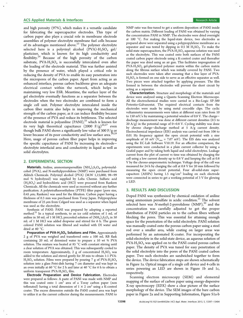
the cross-section of the device gives a clear picture of theexpected high integrity and enhanced electrode−electrolyteinterface within the system (Figure 3a−c). The total thicknessof the device is only 0.80 mm which comprises a fine film of the
gel electrolyte possessing a thickness of 0.12 mm in betweenthe PANI coated carbon paper. The EDX elemental mappingshows the intercalated PANI particles and PVA-H2SO4 insidethe carbon fiber matrix. The nitrogen (N) mapping inSupporting Information, Figure S2a corresponds to the cross-section of the device possessing a catalyst loading of 0.30 mg/cm2, which clearly shows that PANI is uniformly distributedthroughout the matrix and not restricted only at the surface.Similarly, sulfur (S) mapping at the same location as shown inFigure 3a indicates the presence of S into either side of thePVA-H2SO4 film. This unambiguously confirms the diffusion ofPVA-H2SO4 through the carbon fibers, which leads to anintimate electrode−electrolyte interface in the system. Further,the diffusive nature of the solid-electrolyte appeared to bedecreasing with higher loading of PANI, which is clear from thecross-sectional mapping of the corresponding devices which arehaving different PANI loading as shown in Figure 3b and c. Thegradual change in the porosity of the carbon paper with theloading of PANI is clear from Supporting Information, FigureS1d-f. It is clear from these sets of figures that higher loading ofPANI leads to filling of the pores heavily so that the spaceavailable for the intercalation of the polymer electrolyte isdecreasing. The SEM cross-section images and elementalmapping also emphasize the need for special attention to betaken with higher loading of PANI to establish adequateintegrity. Such benefits in establishing extended electrode−electrolyte interfaces will help to achieve very high arealcapacitance without compromising the specific capacitance.This extended and well-distributed interfacial structure nearlymimics an interfacial structure which can be expected in asystem based on the conventional liquid electrolytes.Electrochemical charge storage properties of the PANI
coated electrodes were analyzed initially in acidic mediumcontaining 0.5 M H2SO4 and subsequently the tests were doneusing the systems based on the gel electrolyte. In the case of thetests in 0.5 M H2SO4, the two PANI coated electrodes wereseparated by a polycarbonate film, and the assembly was dippedin the electrolyte. Cyclic voltammograms (CVs) and charge−discharge measurements were recorded by varying the scanrates and current densities from 10 to 150 mV/s and 0.5 to 20A/g, respectively. Since we used symmetrical two electrodes forthe testing, capacitance values calculated from the CV andcharge−discharge profiles were multiplied by a factor of 2 toobtain the capacitance of the single electrode (SupportingInformation, eqs 1 and 2). As mentioned before, we haveprepared nonporous electrodes by coating PANI on Grafoilalong with the PANI coated porous carbon electrodes. Grafoilwith a PANI loading of 1.5 mg/cm2 displays a capacitance of300 F/g when the CV was recorded at a voltage scan rate of 10
Figure 1. (a) Schematics of the ASSP representing the steps involvingthe coating of PANI onto the carbon paper, incorporation of PVA-H2SO4 into the porous PANI/carbon paper, and sandwiching ofelectrodes by applying pressure to make the all-solid-state-super-capacitor. (b) Optical images of 1 cm2 prototype ASSP. (c) LEDpowered by a four-cell assembly connected in series.
Figure 2. SEM images of (a) porous carbon paper, (b) PANI (1.5 mg/cm2) coated carbon paper, and (c) intercalated gel-electrolyte inside thePANI/carbon paper.
ACS Applied Materials & Interfaces Research Article
dx.doi.org/10.1021/am404320e | ACS Appl. Mater. Interfaces 2013, 5, 13397−1340413399
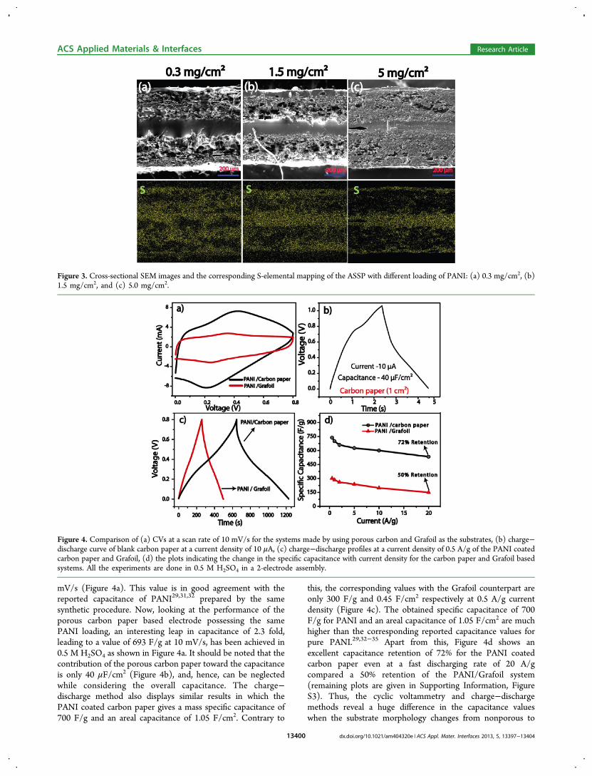
mV/s (Figure 4a). This value is in good agreement with thereported capacitance of PANI29,31,32 prepared by the samesynthetic procedure. Now, looking at the performance of theporous carbon paper based electrode possessing the samePANI loading, an interesting leap in capacitance of 2.3 fold,leading to a value of 693 F/g at 10 mV/s, has been achieved in0.5 M H2SO4 as shown in Figure 4a. It should be noted that thecontribution of the porous carbon paper toward the capacitanceis only 40 μF/cm2 (Figure 4b), and, hence, can be neglectedwhile considering the overall capacitance. The charge−discharge method also displays similar results in which thePANI coated carbon paper gives a mass specific capacitance of700 F/g and an areal capacitance of 1.05 F/cm2. Contrary to
this, the corresponding values with the Grafoil counterpart areonly 300 F/g and 0.45 F/cm2 respectively at 0.5 A/g currentdensity (Figure 4c). The obtained specific capacitance of 700F/g for PANI and an areal capacitance of 1.05 F/cm2 are muchhigher than the corresponding reported capacitance values forpure PANI.29,32−35 Apart from this, Figure 4d shows anexcellent capacitance retention of 72% for the PANI coatedcarbon paper even at a fast discharging rate of 20 A/gcompared a 50% retention of the PANI/Grafoil system(remaining plots are given in Supporting Information, FigureS3). Thus, the cyclic voltammetry and charge−dischargemethods reveal a huge difference in the capacitance valueswhen the substrate morphology changes from nonporous to
Figure 3. Cross-sectional SEM images and the corresponding S-elemental mapping of the ASSP with different loading of PANI: (a) 0.3 mg/cm2, (b)1.5 mg/cm2, and (c) 5.0 mg/cm2.
Figure 4. Comparison of (a) CVs at a scan rate of 10 mV/s for the systems made by using porous carbon and Grafoil as the substrates, (b) charge−discharge curve of blank carbon paper at a current density of 10 μA, (c) charge−discharge profiles at a current density of 0.5 A/g of the PANI coatedcarbon paper and Grafoil, (d) the plots indicating the change in the specific capacitance with current density for the carbon paper and Grafoil basedsystems. All the experiments are done in 0.5 M H2SO4 in a 2-electrode assembly.
ACS Applied Materials & Interfaces Research Article
dx.doi.org/10.1021/am404320e | ACS Appl. Mater. Interfaces 2013, 5, 13397−1340413400
porous even though both are having the same PANI content.This difference can be clearly attributed to the utilization ofhigh porosity carbon paper for achieving enhanced electrode−electrolyte interface for PANI upon its coating on the surface.Fabrication of the ASSP requires replacement of the liquid
electrolyte with the solid electrolyte. The above results usingthe liquid electrolyte clearly indicate the superiority of theporous substrate as the current collector to establish higher areaof the electroactive material. Once this condition is maintained,a proper intercalation by a solid electrolyte which gives a closelymatching interfacial structure with the electrode material isexpected to narrow down the differences in the performancesbetween the solid and liquid systems. To conceive thiscondition, the solid electrolyte, which will mimic the natureof the liquid electrolyte, should lead to very high interfacial areainside the porous current collector. We have overcome thisissue by using PVA-H2SO4 gel polymer electrolyte by in situsolidifying inside the porous current collector which is alreadycoated with PANI, but still bearing enough porosity toaccommodate the gel electrolyte. Since the porosity is still
sufficient inside the PANI/carbon paper for making theintercalated electrode-gel electrolyte interface, the systemmore or less mimics an interfacial structure similar to a casewhere a liquid electrolyte is used.This strategy has been realized successfully as reflected from
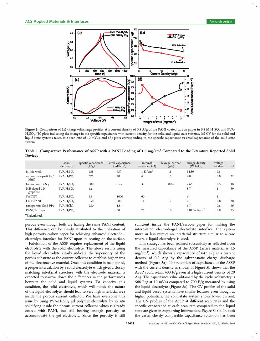
the measured capacitance of the ASSP (active material is 1.5mg/cm2), which shows a capacitance of 647 F/g at a currentdensity of 0.5 A/g by the galvanostatic charge−dischargemethod (Figure 5a). The retention of capacitance of the ASSPwith the current density as shown in Figure 5b shows that theASSP could retain 400 F/g even at a high current density of 20A/g. The capacitance value obtained by the cyclic voltametry is568 F/g at 10 mV/s compared to 700 F/g measured by usingthe liquid electrolyte (Figure 5c). The CV profiles of the solidand liquid based systems have similar features even though athigher potentials, the solid-state system shows lower current.The CV profiles of the ASSP at different scan rates and thespecific capacitance at each scan rate compared to the liquidstate are given in Supporting Information, Figure S4a-b. In boththe cases, closely comparable capacitance retention has been
Figure 5. Comparison of (a) charge−discharge profiles at a current density of 0.5 A/g of the PANI coated carbon paper in 0.5 M H2SO4 and PVA-H2SO4, (b) plots indicating the change in the specific capacitance with current density for the solid and liquid-state systems, (c) CV for the solid andliquid-state systems taken at a scan rate of 10 mV/s, and (d) plots corresponding to the specific capacitance vs areal capacitance of the solid-statesystem.
Table 1. Comparative Performance of ASSP with a PANI Loading of 1.5 mg/cm2 Compared to the Literature Reported SolidDevices
solidelectrolyte
specific capacitance(F/g)
areal capacitance(mF/cm2)
internalresistance (Ω)
leakage current(μA)
energy density(W h/kg)
voltagewindow ref
in this work PVA-H2SO4 638 957 1 Ω/cm2 15 14.36 0.8carbon nanoparticles/MnO2
PVA-H3PO4 675 20 4 15 4.8 0.8 22
hierarchical GeSe2 PVA-H2SO4 300 0.25 30 0.02 2.6a 0.5 18N,B doped 3Dgraphene
PVA-H2SO4 62 8.7 1 39
SWCNT PVA-H3PO4 35 1000 60 6 1CNT-PANI PVA-H2SO4 350 800 11 17 7.1 0.8 20nanoporous Gold-PPy PVA-HClO4 250 1.8 6.7 0.8 36PANI/Au paper PVA-H3PO4 50 25 10 0.01 W h/cm3 0.8 35aCalculated.
ACS Applied Materials & Interfaces Research Article
dx.doi.org/10.1021/am404320e | ACS Appl. Mater. Interfaces 2013, 5, 13397−1340413401

observed with respect to the variation of the voltage scan ratefrom low to high (Supporting Information, Figure S4b). Thecapacitance value of the ASSP is almost 93% of the capacitanceobtained for the liquid state system using 0.5 M H2SO4 by thecharge−discharge method. Charge−discharge profile and thevariation of the specific capacitance with change in currentdensity are given in Supporting Information, Figure S4c-e forthe different PANI loaded samples. The areal capacitance isestimated to be 1 F/cm2 for PANI with its loading of 1.5 mg/cm2.Variation of specific capacitance vs areal capacitance is given
in Figure 5d which is calculated from the charge−dischargemethod. To the best of our knowledge, the specific and arealcapacitances obtained in the present case are the highest everreported for the ASSPs. A comparative literature survey hasbeen given in Table 1. Even at a very high areal capacitance of 2F/cm2, the device shows a specific capacitance of 400 F/g. Itshould be noted that many of the ASSPs reported have verylow areal capacitances in microfarads even though they havehigh specific capacitance22,35,36(Table.1).The specific capaci-
tance could reach up to 850 F/g with a low PANI loading of 0.3mg/cm2, where the areal capacitance is 0.28 F/cm2. Thesevariations are expected and are in accordance with theaforementioned results of the SEM and elemental mapping ofthe cross-section of the devices possessing varying loading ofPANI. As the PANI content increases, the pores are gettingfilled and subsequently most of the PANI particles stay at thesurface and prevent penetration of PVA-H2SO4 into the carbonpaper. This leads to a lower electrode−electrolyte interface,which is clear from the comparative S elemental mapping inFigure 3a−c.For comparing the design of the electrode−electrolyte
interface with the conventional approach involving an ionconducting membrane as a separator between the electrodes,we fabricated a system by sandwiching a PVA-H2SO4 film inbetween the PANI coated carbon papers by hot pressing.Because of the lower electrode−electrolyte contact, the systemgives a significantly low specific capacitance of 150 F/g at 0.5A/g and a PANI loading of 1.5 mg/cm2 (Figure 6 a−b)compared to 647 F/g as obtained in the previous case by
Figure 6. Performance characteristics of the solid-state devices formed by the present approach and the one made by using a polymer film as in thecase of the conventional systems: (a) comparison of the charge−discharge profiles measured at 0.5 A/g current density, (b) comparison of thechange in specific capacitance with varied current. (c) Nyquist plot of the ASSP using PVA-H2SO4 in the present strategy and conventional solid filmmethod with enlarged part of the high frequency region in the inset.
Figure 7. (a) Comparison of the Nyquist plots of the ASSP using PVA-H2SO4 as the electrolyte with the corresponding liquid-state system made byusing 0.5 M H2SO4. (b) Ragone plots created by calculating the energy density and power density from the charge−discharge method; (c) cyclestability test extending for a period of 10000 cycles of the ASSP carried at a current density of 5 A/g; (d) comparative cycle stability done at acharge−discharge current density of 5 A/g in 0.5 M H2SO4 for Grafoil and carbon paper each having a PANI loading of 1.5 mg/cm2. Panels (e) and(f) represent the leakage current measured by keeping the device at 0.8 V and potential drop with respect to time measured after raising the potentialto 0.8 V of ASSP.
ACS Applied Materials & Interfaces Research Article
dx.doi.org/10.1021/am404320e | ACS Appl. Mater. Interfaces 2013, 5, 13397−1340413402

applying the gel-electrolyte directly on the electrodes. Apartfrom the lower specific capacitance, the device also shows verylow capacitance retention (27% when the current directlyincreased to 20 A/g from 0.5 A/g). The high internal resistanceof 20 Ω/cm2 (Figure 6) measured from the x-intersect of theNyquist plot of impedance analysis validates the reason for thepoor capacitance retention of the system. This clearly shows theadvantages of our design to enhance the electrode−electrolyteinterface rather than having a solid film between the electrodes.Impedance analysis of the ASSP confirms the high charge
storage properties obtained by both cyclic voltammetry andchrono charge−discharge methods. The high retention ofcapacitance under fast charge−discharge conditions is possibleonly if the system assists very fast ion diffusion in response tothe large perturbation. Two factors which have the key rolehere are the ESR and the charge-transfer resistance. EstimatedESR from the Nyquist plot of the device is only 1 Ω/cm2
(Figure 7a). The liquid and solid systems have only 0.1 Ωdifferences, which explain the superior power rate and highretention of the ASSP. It is also interesting to note that the ESRof the solid device made by using the PVA-H2SO4 film shows ahuge ESR of 20 Ω/cm2 (Figure 6c). Further, in our ASSP, wecould not resolve the characteristic high frequency semicircleeven in the zoomed image in Figure 7a, confirming that there isvery less charge-transfer resistance in the system.Energy density and power density are calculated from the
charge−discharge method after excluding the weight of thecarbon paper and electrolyte. The corresponding Ragone plot isshown in Figure 7b. The PANI in the solid device shows anenergy density of 14.3 Wh/kg at a power density of 105 W/kgcompared to 3.3 W h/kg of the device which uses a polymerfilm. The energy density obtained here is probably the highestamong the other reported values of ASSPs (Table 1). At ahigher power rate of 5.6 kW/kg, the ASSP based on the currentapproach could keep an energy density of 8.8 W h/kg whereasthe film based system shows an energy density of only 1.1 W h/kg at a power rate of 2.3 kW/kg. The volumetric energy densityof the whole device including the carbon paper and the solidelectrolyte is 0.53 mWh/cm3.Extended cycling stability is an essential criterion for any
charge storage devices. It is found that the architectureimproves the stability along with the capacitance. We carriedout 10000 continuous cycling at a current density of 5 A/g ofASSP which was showing a capacitance of 638 F/g. Percentagecapacitance retention and coulombic efficiency during the10000 cycles are plotted in Figure 7c. Excellent stability wasobtained during the cycling with less than 2% degradation andnearly 100% coulombic efficiency during the entire cycling. Incontrast to the low stability of PANI in liquid electrolyte(Figure 7d), the enhanced stability of PANI in ASSP is clearlyexplained by the role of PVA as the binder. Apart from the roleas the electrolyte matrix in the device, PVA also plays anintegral role by providing a means to hold the PANI moietytightly. On the other hand, in the liquid electrolyte, the relativemovement of the electrolyte will enhance the detachment ofthe electrode material from the electrode as we have notapplied any extra binder for ensuring mechanical stability. Theobtained cycle stability of the solid supercapacitors is muchsuperior to those in the literature reports.20,29,37
The prototype device made here is a significantly lightweightassembly because of the low density of the carbon paper. Thewhole device has a weight of only 110 mg (SupportingInformation, Figure S5d) including the space given for the
contact, which is inactive in terms of charge storage. The wholedevice including the electrolyte shows a capacitance of 12.5 F/g, which is double as compared to the commercially availablesupercapacitors with liquid electrolytes.38 It should be notedthat the amount of the polymer electrolyte can still be reducedas we have given extra thickness (120 μm) between theelectrodes. This will further decrease the whole device weight.The whole device dimension is also very promising as thethickness is only 0.8 mm. Leakage current and self-dischargevalues are two essential parameters of supercapacitors in termsof the practical usage. We measured the leakage current of thedevice by charging at 0.8 V and by monitoring the currentrequired to maintain that potential. Normally, the leakagecurrent of the supercapacitors is higher than that in the Li-ionbatteries. Here, the device leakage current is only 50 μA at 200s, which reached to 16 μA at 2000 s (Figure 7e). This value isless compared with the values reported in the literature.20 Thedevice could hold 0.25 V even at 24 h which is also comparableto the literature values22 (Figure 7f). Further, we connectedfour such devices in series to make an LED glow whoseminimum working potential was 2 V as shown in Figure 1c.The LED could be made to glow more than 1 min, and theintensity of its illumination diminishes when the potentialreaches to 2 V (see Supporting Information video). The CV at10 mV/s and the charge−discharge profile at 10 mA of theabove coupled device are shown in Supporting Information,Figure S6a−-b.
4. CONCLUSION
In conclusion, we have reported a high performance ASSPmade by intercalating a gel-polymer electrolyte, that is, PVA-H2SO4, with PANI-coated carbon paper, which in turnenhances the electrode−electrolyte interface of the resultingdevice. The gel electrolyte also simultaneously serves as theseparator between the electrodes when the electrodes arecombined together to form a cell. Cross-sectional elementalmapping and SEM images display the proof of concept. Theenhanced interface helps the solid device to perform like aliquid counterpart showing a specific capacitance of 647 F/g forPANI with an areal capacitance of 1 F/cm2 at 0.5 A/g. It showsa retention of 62% of its capacitance at a current density of 20A/g. High integrity of the electrode−electrolyte phases helpsthe device to attain a very low ESR of 1 Ω/cm2. The deviceshows excellent cycle stability and coulombic efficiency. Thisapproach could significantly narrow down the differencebetween the charge storage properties of the solid- andliquid-state supercapacitor devices. The strategy conceived hereis not restricted only to PANI, but can also be further applied todifferent charge storage materials in conjunction with highlyporous and conducting substrates. Thus, the evolved concepthas the potential to make significant advancements in theenergy storage technologies by providing efficient lighter,thinner, safer, and cheaper electric devices.
■ ASSOCIATED CONTENT
*S Supporting InformationCalculation of capacitance, energy density, power density, andconductivity. SEM images of Carbon paper, Grafoil, and PANI/coated carbon paper. Cross sectional Nitrogen mapping of theASSPs. Detailed CV and charge discharge curves of varioussamples. CV and charge discharge curve of four ASSPsconnected in series. Video (.avi format) showing ASSPs
ACS Applied Materials & Interfaces Research Article
dx.doi.org/10.1021/am404320e | ACS Appl. Mater. Interfaces 2013, 5, 13397−1340413403

powered LED glow. This material is available free of charge viathe Internet at http://pubs.acs.org.
■ AUTHOR INFORMATION
Corresponding Author*E-mail: [email protected].
NotesThe authors declare no competing financial interest.
■ ACKNOWLEDGMENTS
Special thanks go to Dr. S. Pal, Director, NCL, Pune, for hiscontinuous encouragement. B.A. and K.S. acknowledge CSIRand DST (Project No. SR/S1/PC-05/2011), respectively forthe financial assistance
■ ABBREVIATIONS
ASSP, All-solid-state-supercapacitor; PANI, Polyaniline
■ REFERENCES(1) Yang, Z.; Zhang, J.; Kintner-Meyer, M.; Lu, X.; Choi, D.;Lemmon, J.; Liu, J. Chem. Rev. 2011, 111, 3577−3613.(2) Palacin, M. R. Chem. Soc. Rev. 2009, 38, 2565−2575.(3) Choi, N. S.; Chen, Z.; Freunberger, S. A.; Ji, X.; Sun, Y. K.;Amine, K.; Yushin, G.; Nazar, L. F.; Cho, J.; Bruce, P. G. Angew. Chem.,Int. Ed. 2012, 51, 9994−10024.(4) Conway, B. E. Electrochemical Supercapacitors: ScientificFundamentals and Technological Applications; Plenum Press: NewYork, 1999; p 1.(5) Winter, M.; Brodd, R. J. Chem. Rev. 2004, 104, 4245−4270.(6) Simon, P.; Gogotsi, Y. Nat. Mater. 2008, 7, 845−854.(7) Arbizzani, C.; Mastragostino, M.; Soavi, F. J. Power Sources 2001,100, 164−170.(8) Zhang, Y.; Feng, H.; Wu, X.; Wang, L.; Zhang, A.; Xia, T.; Dong,H.; Li, X.; Zhang, L. Int. J. Hydrogen Energy 2009, 34, 4889−4899.(9) Vellacheri, R.; Pillai, V.; Kurungot, S. Nanoscale 2012, 4, 890−896.(10) Catia, A.; Maurizio, B.; Dario, C.; Mariachiara, L.; Francesca, S.;Marina, M. J. Power Sources 2008, 185, 1575−1579.(11) Wright, P. V. Electrochim. Acta 1998, 43, 1137−1143.(12) Song, J. Y.; Wang, Y. Y.; Wan, C. C. J. Power Sources 1999, 77,183−197.(13) Agrawal, R. C.; Pandey, G. P. J. Phys. D: Appl. Phys. 2008, 41,223001.(14) Kyung-Won, P.; Hyo-Jin, A.; Yung-Eun, S. J. Power Sources2002, 109, 500−506.(15) Lewandowski, A.; Zajder, M.; Frackowiak, E.; Beguin, F.Electrochim. Acta 2001, 46, 2777.(16) White, A. M.; Slade, R. C. T. Synth. Met. 2003, 139, 123.(17) Dhanraj, R.; Meenu, V.; Nazrul, I.; Ramaiyan, K.; Ulhas, K.;Sreekumar, K.; Vijayamohanan, P. J. Appl. Electrochem. 2009, 39,1097−1103.(18) Wang, X.; Liu, B.; Wang, Q.; Song, W.; Hou, X.; Chen, D.;Cheng, Y.-B.; Shen, G. Adv. Mater. 2013, 25, 1479.(19) Kaempgen, M.; Chan, C. K.; Ma, J.; Cui, Y.; Gruner, G. NanoLett. 2009, 9, 1872−1876.(20) Meng, C.; Liu, C.; Chen, L.; Hu, C.; Fan, S. Nano Lett. 2010, 10,4025−4031.(21) Yuan, L.; Xiao, X.; Ding, T.; Zhong, J.; Zhang, X.; Shen, Y.; Hu,B.; Huang, Y.; Zhou, J.; Wang, Z. Angew. Chem., Int. Ed. 2012, 51,4934−4938.(22) Yuan, L.; Lu, X.-H.; Xiao, X.; Zhai, T.; Dai, J.; Zhang, F.; Hu, B.;Wang, X.; Gong, L.; Chen, J.; Hu, C.; Tong, Y.; Zhou, J.; Wang, Z.ACS Nano 2012, 6, 656−661.(23) Mehta, V.; Cooper, J. J. Power Sources 2003, 32−53.
(24) Haijun, Y.; Jihuai, W.; Leqing, F.; Youzhen, L.; Kaiqing, X.;Ziying, T.; Cunxi, C.; Shen, T.; Jianming, L.; Miaoliang, H.; Zhang, L.J. Power Sources 2012, 198, 402−407.(25) MacDiarmid, A. G.; Epstein, A. J. J. Chem. Soc., Faraday Trans.1989, 88, 317.(26) Peng, C.; Hu, D.; Chen, G. Z. Chem. Commun. 2011, 47, 4105−4107.(27) Li, H.; Wang, J.; Chu, Q.; Wang, Z.; Zhang, F.; Wang, S. J. PowerSources 2009, 190, 578−586.(28) Snook, G. A.; Kao, P.; Best, A. S. J. Power Sources 2011, 196, 1−12.(29) Wu, Q.; Xu, Y.; Yao, Z.; Liu, A.; Shi, G. ACS Nano 2010, 4,1963−1970.(30) Jain, R.; Gregory, R. Synth. Met. 1995, 74, 263−266.(31) Ghosh, D.; Giri, S.; Mandal, A.; Das, C. K. RSC Adv. 2013, 3,11676−11685.(32) Zhang, H.; Wang, J.; Chen, Y.; Wang, Z.; Wang, S. Electrochim.Acta 2013, 105, 69−74.(33) Liu, J.; Zhou, M.; Fan, L.-Z.; Li, P.; Qu, X. Electrochim. Acta2010, 55, 5819−5822.(34) Jyongsik, J.; Joonwon, B.; Moonjung, C.; Seong-Ho, Y. Carbon2005, 43, 2730−2736.(35) Yuan, L.; Xiao, X.; Ding, T.; Zhong, J.; Zhang, X.; Shen, Y.; Hu,B.; Huang, Y.; Zhou, J.; Wang, Z. Angew. Chem., Int. Ed. 2012, 51,4934−4938.(36) Meng, F.; Ding, Y. Adv. Mater. 2011, 23, 4098−4102.(37) Ying-Ying, H.; Yi-Chen, L.; Yu-Kuei, H.; Chia-Chun, C.; Li-Chyong, C.; Kuei-Hsien, C. J. Power Sources 2010, 195, 4418.(38) Chu, A.; Braatz, P. J. Power Sources 2002, 112, 236−246.(39) Wu, Z.-S.; Winter, A.; Chen, L.; Sun, Y.; Turchanin, A.; Feng,X.; Mullen, K. Adv. Mater. 2012, 24, 5130−5135.
ACS Applied Materials & Interfaces Research Article
dx.doi.org/10.1021/am404320e | ACS Appl. Mater. Interfaces 2013, 5, 13397−1340413404
Copyright © 2022 FDOKUMEN