Design of a deployment rotation mechanism for microsatellite
8
Int. J. Simul. Multidisci. Des. Optim. 3, 289-296 (2009) © ASMDO 2009 DOI: 10.1051/ijsmdo:2009001 Available online at: http://www.ijsmdo.org a corresponding Author [email protected] Design of a deployment rotation mechanism for microsatellite G. F. Abdelal 1a , A. Bakr Elhady 2 , M. Kassab 2 1 Research Assistant Professor, Aerospace Structures Chair, Delft University of Technology, Delft, Netherlands. 2 Egyptian Space Program, National Authority for Remote Sensing and Space Science Received 15 July 2008, Accepted 15 November 2008 Abstract – Solar array rotation mechanism provides a hinged joint between the solar panel and satellite body, smooth rota- tion of the solar array into deployed position and its fixation in this position. After unlocking of solar panel (while in orbit), rotation bracket turns towards ready-to-work position under the action of driving spring. During deployment, once reached the required operating angle (defined by power subsystem engineer), the rotation bracket collides with the fixed bracket that is mounted on body of the satellite, to stop rotation. Due to the effect of collision force that may alter the rotation mechanism function, design of centrifugal brake is essential. At stoppage moment micro-switches activate final position sensor and a stopper locks the rotation bracket. Design of spring and centrifugal brake components, static finite element stress analysis of primary structure body of rotation mechanism at stoppage moment have been obtained. Last, reliability analysis of rotation mechanism is evaluated. The benefit of this study is to aid in the design of rotation mechanism that can be used in micro-satellite applications. Key words: Aerospace, Satellite, Structure, Rotation Mechanism, Spring, Centrifugal Brake, Finite Element, Reliability. Nomenclature J the moment of inertia of a rotation element (the solar panel array) concerning an axis of rota- tion;kg.m 2 J r the moment of inertia of rotating parts of the me- chanism; kg.m 2 Ф the current rotation angle counted from initial po- sition of a rotation element; (rad.) М res the total moment of forces of resistance; Kgf.mm М c the moment of resistance to bend a cable; Kgf.mm λ factor taking into account rigidity of a cable at various temperatures (it is defined experimen- tally). М f.c.b the resulted moment of friction due to resist the rotation part of centrifugal brake with internal sur- face of the cartridge; Kgf.mm M f the moment of friction in centrifugal brake multi- plication ratio of gears in centrifugal brake; Kgf.mm C rigidity of a spring. М m.s the moment needed to overcome of micro switch resistance. F the force necessary for operation of the micro switches; Kgf.mm К 0 factor curvature. М 1 the working moment of a spring corresponding to the final position of solar panels; Kgf.mm М 2 the working moment of a spring corresponding to the initial position of solar panels; Kgf.mm Ф 1 the working compression angle of a spring corre- sponding to the final position of solar panels; de- gree. Ф 2 the working compression angle of a spring corre- sponding to the initial position of solar panels; de- gree. ϕ" angular acceleration; r/s 2 α angle of an inclination of coils of the spring; de- gree ω Angular velocity at the end of accelerating of the panel; r/seс t acc time of accelerating of solar panel, seс V linear velocity of rotation of the center of gravity of panel; m/s 2 R radius of rotation of the center of gravity of panel; mm N normal reaction of the cartridge working; kgf a shoulder of action of force N concerning an axis of rotation B; mm F f friction force; kgf d shoulder of action of force F f concerning an axis of rotation B; mm Р c centrifugal force; kgf b shoulder of action of force Р c concerning an axis of rotation; m М spr the moment of a centrifugal brake spring; kgf.mm ρ distance from an axis of rotation to the center of gravity; mm G weight of rotation part of centrifugal brake; Kgf ω o angular velocity of rotation of axis (B) about the center of rotation (O); r/seс f factor of friction between pair of rotation parts and the inner surface of the case (steel - bronze), f = 0.18; 1 Introduction Rotation mechanism assembly consists from three subas- semblies [1 – 4]. Each subassembly consists from three to Article available at http://www.ijsmdo.org or http://dx.doi.org/10.1051/ijsmdo/2009001
-
Upload
independent -
Category
Documents
-
view
0 -
download
0
Transcript of Design of a deployment rotation mechanism for microsatellite

Int. J. Simul. Multidisci. Des. Optim. 3, 289-296 (2009) © ASMDO 2009 DOI: 10.1051/ijsmdo:2009001
Available online at: http://www.ijsmdo.org
a corresponding Author [email protected]
Design of a deployment rotation mechanism for micro satellite G. F. Abdelal1a, A. Bakr Elhady2, M. Kassab2
1 Research Assistant Professor, Aerospace Structures Chair, Delft University of Technology, Delft, Netherlands. 2 Egyptian Space Program, National Authority for Remote Sensing and Space Science
Received 15 July 2008, Accepted 15 November 2008
Abstract – Solar array rotation mechanism provides a hinged joint between the solar panel and satellite body, smooth rota-tion of the solar array into deployed position and its fixation in this position. After unlocking of solar panel (while in orbit), rotation bracket turns towards ready-to-work position under the action of driving spring. During deployment, once reached the required operating angle (defined by power subsystem engineer), the rotation bracket collides with the fixed bracket that is mounted on body of the satellite, to stop rotation. Due to the effect of collision force that may alter the rotation mechanism function, design of centrifugal brake is essential. At stoppage moment micro-switches activate final position sensor and a stopper locks the rotation bracket. Design of spring and centrifugal brake components, static finite element stress analysis of primary structure body of rotation mechanism at stoppage moment have been obtained. Last, reliability analysis of rotation mechanism is evaluated. The benefit of this study is to aid in the design of rotation mechanism that can be used in micro-satellite applications.
Key words: Aerospace, Satellite, Structure, Rotation Mechanism, Spring, Centrifugal Brake, Finite Element, Reliability.
Nomenclature J the moment of inertia of a rotation element (the
solar panel array) concerning an axis of rota-tion;kg.m2
Jr the moment of inertia of rotating parts of the me-chanism; kg.m2
Ф the current rotation angle counted from initial po-sition of a rotation element; (rad.)
Мres the total moment of forces of resistance; Kgf.mm
Мc the moment of resistance to bend a cable; Kgf.mm λ factor taking into account rigidity of a cable at
various temperatures (it is defined experimen-tally).
Мf.c.b the resulted moment of friction due to resist the rotation part of centrifugal brake with internal sur-face of the cartridge; Kgf.mm
M f the moment of friction in centrifugal brake multi-plication ratio of gears in centrifugal brake; Kgf.mm
C rigidity of a spring. Мm.s the moment needed to overcome of micro switch
resistance. F the force necessary for operation of the micro
switches; Kgf.mm К0 factor curvature. М1 the working moment of a spring corresponding to
the final position of solar panels; Kgf.mm М2 the working moment of a spring corresponding to
the initial position of solar panels; Kgf.mm Ф1 the working compression angle of a spring corre-
sponding to the final position of solar panels; de-gree.
Ф2 the working compression angle of a spring corre-sponding to the initial position of solar panels; de-gree.
ϕ" angular acceleration; r/s2 α angle of an inclination of coils of the spring; de-
gree ω Angular velocity at the end of accelerating of the
panel; r/seс tacc time of accelerating of solar panel, seс V linear velocity of rotation of the center of gravity
of panel; m/s2 R radius of rotation of the center of gravity of panel;
mm N normal reaction of the cartridge working; kgf a shoulder of action of force N concerning an axis of
rotation B; mm Ff friction force; kgf d shoulder of action of force Ff concerning an axis of
rotation B; mm
Рc centrifugal force; kgf b shoulder of action of force Рc concerning an axis of
rotation; m
М spr the moment of a centrifugal brake spring; kgf.mm
ρ distance from an axis of rotation to the center of gravity; mm
G weight of rotation part of centrifugal brake; Kgf
ω o angular velocity of rotation of axis (B) about the center of rotation (O); r/seс
f factor of friction between pair of rotation parts and the inner surface of the case (steel - bronze), f = 0.18;
1 Introduction Rotation mechanism assembly consists from three subas-semblies [1 – 4]. Each subassembly consists from three to
Article available at http://www.ijsmdo.org or http://dx.doi.org/10.1051/ijsmdo/2009001
290 G.F.Abdelal et al: Design of deployment rotation mechanism for microsatellite
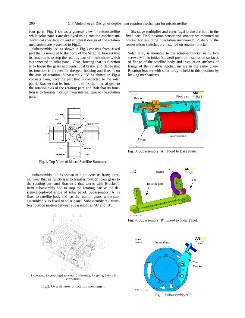
four parts. Fig. 1 shows a general view of microsatellite while solar panels are deployed using rotation mechanism. Technical specification and structural design of the rotation mechanism are presented in Fig.2.
Subassembly ‘A’ as shown in Fig.3 consists from; fixed part that is mounted to the body of the Satellite, bracket that its function is to stop the rotating part of mechanism, which is connected to solar panel, Gear Housing that its function is to house the gears and centrifugal brake, and flange that its function is a cover for the gear housing and fixes it on the axis of rotation. Subassembly ‘B’ as shown in Fig.4 consists from; Rotating part that is connected to the solar panel, Bracket that its function is to fix the internal gear to the rotation axis of the rotating part, and Bolt that its func-tion is to transfer rotation from internal gear to the rotation part.
Fig.1. Top View of Micro-Satellite Structure.
Subassembly ‘C’ as shown in Fig.5 consists from; Inter-
nal Gear that its function is to transfer rotation from gears to the rotating part and Bracket-2 that works with Bracket-1 from subassembly ‘A’ to stop the rotating part at the de-signed deployed angle of solar panel. Subassembly ‘A’ is fixed to satellite body and has the rotation gears, while sub-assembly ‘B’ is fixed to solar panel. Subassembly ‘C’ trans-fers rotation motion between subassemblies ‘A’ and ‘B’.
М П 1
М П 2
1 - housing, 2 - centrifugal governor, 3 – housing, 4 – spring, 5,6 – mi-
croswitches
Fig.2. Overall view of rotation mechanism
Six-stage multiplier and centrifugal brake are built in the fixed part. Final position sensor and stopper are mounted on bracket for mounting of rotation mechanism. Pushers of the sensor micro switches are installed on rotation bracket.
Solar array is mounted to the rotation bracket using two screws M4. In initial (stowed) position installation surfaces of flange of the satellite body and installation surfaces of flange of the rotation mechanism are in the same plane. Rotation bracket with solar array is held in this position by locking mechanisms.
Fig. 3. Subassembly ‘A’, Fixed to Base Plate.
Fig. 4. Subassembly ‘B’, Fixed to Solar Panel.
Fig. 5. Subassembly ‘C’.
Fixed part
Gear housing Flange
Bracket
Brack
Rotating part Bolt
Bracket
Internal gear

International Journal for Simulation and Multidisciplinary Design Optimization 291
Rotation bracket together with solar array turns towards ready-to-work position under the action of driving spring after unlocking. Gear of the drive shaft puts the centrifugal brake in action. Mass of the rotation mechanism is 0.22 kg, as recommended by satellite configuration engineer. Rotation mechanisms of mechanical (spring) type work with the use of a various kind of elastic energy sources with special centrifugal brake devices to reduce the rotation ve-locity of a rotation element.
Once Micro-Satellite is in orbit, the solar panels are de-ployed to resume their function. Solar panels are deployed through Rotation Mechanism with acceleration α(t). Re-sults from solar panel simulation (forces and moments at fixation nodes) are applied here as loads.
2 Description of motion The rotation element, for example the solar panel array,
by means of the gear multiplier is connected to a centrifugal brake.
At achievement of angular speed ω C the centrifugal brake creates the moment of friction, which slows down rotation of a rotation element. The differential equation of a rotation element movement around an axis of rotation of the spring mechanism with a centrifugal brake is expressed by the next formula:
( )J J ϕ+ = ∑ɺɺ М - Мr res (1)
М - the working moment of a torsion spring,( М=f(Ф)). The total moment of resistance (Мres = Мc + Мf.c.b). Мc de-pends on temperature of the cable that transfers power from solar panel to the power subsystem. It is necessary to expect for possible extreme values of that moment. It is possible to present the following expression; (Мc = λ М0), Where, М0 is the value of the initial moment developed by spring drive. At maximum value; Мc max = λ max М0; (should satisfy condition, λ max< 1).
. .
2.
,f c bM f
i
ϕ =
=f.c.b f
f
М М
f (2)
Thus, the basic components of the total moment of resis-tance are the moment of resistance to bend a cable during rotation and the resulted moment of friction due to centrifu-gal brake. Thus, for any considered type of a drive the gen-eralized differential equation of movement of a rotation element becomes:
( ) . .f c bJ J ϕ λ+ = − −ɺɺr 0 M M М (3)
Then the equation (1)can be rewritten down as follows:
20J c M M iϕ ϕ λΣ = − −ɺɺ f (4)
The solution of this differential equation is a complex mathematical equation; therefore we use a traditional tech-nique of engineering calculation with four basic steps:
1. Determine the general initial geometrical and physical parameters;
2. Definition of the necessary gear multiplier, which provides the suitable operating rotation time;
3. Definition of a design of the torsion spring of the rotation mechanism;
4. Definition of a design of the brake device and cal-culate the opening time of the mechanism.
3 Initial design The moment of inertia of solar array panel relative to
the rotation mechanism axes (Calculated by Satellite con-figuration engineer) = 0.017 (0.167) kgf.m.seс
2 (kg.m2), Solar array panel rotation angle (Requirements given by satellite system engineer) = 90 deg., Time of rotation of solar array panel not less than (Requirements given by satellite structure and mechanisms engineer) = 1.5 sec., External diameter of the rotation mechanism case (Re-quirements given by satellite structure and mechanisms engineer) = 35 mm., Weight of the mechanism not more than (Requirements given by satellite configuration engi-neer) = 0.22 Kgf.
4 Spring design We determine the moment of forces of resistance,
which the spring [5-6] should overcome at the end of rota-tion (MR):
R m.s c
m.s
M =2M +M
M F L= (5)
F ranges from 0.1:0.23 kgf (given by micro-switch sup-plier); for calculation we choose maximum force F=0.23 kgf.
The normal distance of the arm of force to the button
of micro switch (L = 0.024m). In our mechanism 2 micro switches are used (2Мm.s = 0.01104 kgf.m), one switch is basic and the other is redundant. Мc is determined experimentally by YOZHNOYE Design Office Denpropetrovsk UKRAINE, which equals 0.07 kgf.m. Taking into account possible discrepancies at car-rying out of experiment, so, we enter a factor of stock T0 = 1.3;
c 0
R m.s c
M = (0.07)( T ) = 0.091 kgf.m
M = 2M +M = 0.102kgf.m (6)
According to the document working on the enterprise [7],
there will be a deviation due to manufacturing conditions. It is limited in ±10 %, then МR = (0.102)(1.1) = 0.112 Kgf.mm.
For spring material it is chosen; a wire of steel 12Х18Н10Т [8]; d = 2.81mm; Е = 1.85x10⁴ kgf/mm2; σu = (175…205) kgf/mm2; σall = 123 kgf/mm2. Structurally, for the spring we assume; External diameter of the spring D1 = 30.97mm, internal diameter of the spring D2 = 25.35mm,

292 G.F.Abdelal et al: Design of deployment rotation mechanism for microsatellite
and average diameter of the spring D = 28.16mm. Maxi-mum permissible torsion moment of the spring:
[ ]3all
maxo
o
π×d × σM = = 247.369
32×K
4j -1K =
4j - 4
D 28.16j = = =10.02258
d 2.81
(7)
Assume M1 equals the minimum resistance moment MR, while M3 equals the maximum resistance moment Mmax. Assume M2 is less than Mmax (M2 = 240 Kgf.mm). The rotation angle is specified: (φ2 - φ 1 = 900). Determine rigidity of the spring:
2 1
2 1
M -Mc =
j - j
240 -112 = =1.422 Kgf.mm/deg
90
(8)
Angles of a twisting:
ϕ
ϕ
ϕ
011
022
033
M= = 78.75 ,
cM
= =168.75 ,c
M= =173.93
c
(9)
φ1 = 79 0 (as 78.75 0 is immeasurable), thus; М1 = φ1. с = 112.35 Kgf.mm; φ 2 = φ 1 + 900 = 1690; М2 = φ2. с = 240.35
Kgf.mm. Rigidity of one coil of the spring C ’ :
4
/ E×dC = =11.16939 Kgf.mm/deg
64×D×(57.3) (10)
Number of working coils of the spring n, '
7.85Cn C= = .
We specify maximum permissible twisting angle of the spring,
ϕ oall
30
360×D× ×n= =166
d×E×Kσ (11)
Take clearance between turns of the spring f3' [9],
′ ′
'3
33
f= 0.45 ±0.20,
df
f = d = (0.45 ±0.20) (2.81)d
(12)
Pitch of a spring, (t = f3'+d =4.07 mm). Length of a work-
ing part of the non-loaded spring (l0= t.n+d =33.33 mm). Mean diameter (D’) of the spring after loaded with moment M2 is,
( )ϕ
′2 rad
DD = = 26.5 mm
1+2π×n
(13)
Internal diameter of a spring after loaded with moment M2,
2 23.69D D d mm′ ′= − = . Increase in length of the spring
after loaded with moment M2:
ϕ
′2
3
D∆l = Sinα =1.9 mm,2d+ f
tanα =π×D
(14)
Length of the spring after loaded with moment M2, 0 35.24L l l= + ∆ = . Axial length of the developed
spring without taking into account hooks, La = (3.2) D.n = 675.84 mm. Increase the length of the spring at the two ends by 5 mm for hooks, the total axial length of the spring, La tot = 675.84+(2)(5)=685.84 = 686 mm. Mass of the spring,
(((( ))))-6 3G = V.γ = 33.393 gm, γ = 7.85 *10 Kgf/mm , 2 3
a totV = π * r * L = 4254.28 mm .
5 Determination of the spring accelerating moment
The moment of force necessary for accelerating of solar panel after release:
res inertia c m.s
interia s.p
ΣM = M + M + 2.M
M = J
Vω = rad/secR
ϕϕϕϕɺɺɺɺɺɺɺɺ (15)
Velocity of the center of gravity of the center of mass of solar panel (V = πDn), where n is number of revolution per seconds, ω = 2πn r/s. Summation of all resistance moments equal, (∑Мres = Мinertia + Мc + 2Mm.s = 0.11817 Kgf.m). There will be a deviation due to manufacturing conditions that is limited in ±10%, so ∑Мres = (1.1)(118.17) = 129.98 Kgf.mm.
6 Design of speed regulator The speed regulator composed of a centrifugal brake
and gear multiplicator. The gear multiplicator engaged with the rotating part of the rotation mechanism by means of an epicyclical gear integrated with the rotary case. As well as the second end of the gear multiplicator is connected to the centrifugal brake. The principle of centrifugal braking is dissipating a part of the mechanical energy stored in the spring during rotation of the solar panel and transforms it to thermal energy due to friction between the high speed rotation part and the case surface of the brake device. This process leads to a decrease in the angular velocity of the solar panel rotation and the total time needed to complete the rotation. The centrifugal brake is shown in Fig.6. To determine ωo, write the moment equation around the hinge B:

International Journal for Simulation and Multidisciplinary Design Optimization 293
f spr c
2 fc o
2o spr
f
N a + F d + M - P b = 0
FGP = ω ρ, N =
g f
Gω ρb -M
gF =
a+ d
f
(16)
At the moment, ωo = ω o.crit., the sum of the moments of forces of friction concerning an axis of rotation (O) of a framework counterbalances moment Mo:
f o2 F r = M (r is radius of case) (17)
Substituting value Ff, we receive:
2o spr
o
G[( ).ω .ρ.b -M ]
gM /2r =
a( + d)f
(18)
ospr
o.crit.
M a+ d +M
2r fω = g
Gρb
(19)
spr
oo .crit. o
M1 a+ d +
2r f Mω = KM , K = g
Gρb
(20)
Mspr at small speed of rotation or at case of rest, should
provide contact between mass to the hub of a framework, Mspr. =G.L. Where G is the mass of centrifugal brake, =0.0049 kgf, and L is the distance between the center of gravity of the rotating part and its hinge. = 6.12 mm. Mspr. =0.0299 kgf.mm. According to the document [10], there will be a deviation due to manufacturing conditions. It is limited in ±10%, then Mspr. =(0.0299)(1.1)=0.033 Kgf.mm. We shall determine ω o.crit. for two cases, at M1 and at M2 of the driving spring of the mechanism. There are correspond-ingly two of rotation moments of centrifugal brake spring,
1 21 o 2 o
M MM = η, M = η
i i (21)
Where i –multiplication ratio of gears; (i = 276, 5476). η –multiplier efficiency,
1 2 3 4 5
2 21
η = η .η .η .η .η .η
M Mη =1- [(f).(µ)( ± )]
i i
(22)
Where: µ = 0.1, f = 2.6, and (+) denotes to external missing while (-) denotes to internal missing.
η ηη ηη η
= == == =
1 2 3 4 5 6
1 2
3 4
5 6
η = η .η .η .η .η .η = 0.86
0.966 0.975
0.975 0.975
0.971 0.995
At M1=112.35 kgf.mm; 1
1 o
MM = η = 0.3611
i kgf.mm
At M2 = 240.35 kgf.mm; 12 o
MM = η = 0.7725
i kgf.mm
The dimension values of centrifugal brake parameters are:
a = 4,667 mm; b = 5,013 mm; r = 8,75 mm; ρ = 5,765 mm;
d = 5,833 mm.
Then: 1 132057.9819K = and 2 128686.4431K =
218.37 rad/sec
= 12511.768 deg / sec
o crit. min 1 1 oω = K ×M
====
=o crit. max 2 2 oω = K ×M
315.2939 rad/sec
= 18065.0128 deg / sec
By means of transmission gear ratio, these angular ve-
locities are transmitted to the movable part,
ω - the current angular velocity of rotation of a rotating element of R.M
ω min - the minimum angular velocity of rotation of a rotat-ing element of R.M
ω max - the maximum angular velocity of rotation of a rotat-ing element of R
min o crit. min
max o crit. max
= / i
= 46.764 deg / sec
= / i
= 67.520 deg /sec
ω ω
ω ω
Roughly we determine average angular velocity of rotation of a rotating element of R.M:
=min maxav
ω +ωω = 57.142 deg./sec
2
Average time of rotation of a solar panel array to an
angle 900, Тav = 90 / 57.142 = 1.6 sec, which satisfies the required time (T=1.5 sec).
294 G.F.Abdelal et al: Design of deployment rotation mechanism for microsatellite
(a)
(b)
Fig.6. Centrifugal Brake of Rotation Mechanism.
7 Stress analysis of rotation mechanism Mathematical model of rotation mechanism is con-
structed using finite element computer package (ANSYS). Each finite element package provides a library of structure elements, such as beams, shells, and solid elements. The RM is modeled by connecting elements together with ge-ometry, material properties, and boundary conditions ap-propriate to model the design [11-12]. Details of geometry and boundary conditions are discussed in the next section.
Forces and Moments obtained from solar panel analysis are given by satellite structure strength analysis engineer,
Fx = -12.90775, Fy = -0.533E-5, Fz = -16.50722 Kg.mm / s2. Mx = 7280.538, My = -5794.947, Mz = 574.5542 Kg.mm2/ s2.
Strength analysis of rotation mechanism is performed to
check if the RM structure will stand its loads at stoppage moment. It is recommended to run modal analysis to make sure the natural frequencies of solar panel will not match the RM ones. Material is AMГ6 and assumed to be linear iso-tropic. (E = 69 E+6 Kg.mm/s2/mm2, σU = 320 MPa, σY = 200 MPa). Solid45 elements are used which has 8 nodes to save model space. it is recommended to use Solid92 elements.
7.2 Analysis technique Each subassembly consists from different mechanical
parts. These mechanical parts are fixed together through bolts. The analysis for these bolts is not preformed for the simplification of the model. So, these mechanical parts are fixed together.
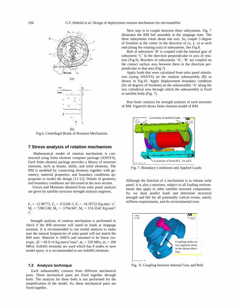
Next step is to couple between three subsystems. Fig. 7 illustrates the RM full assembly at the stoppage time. The three subsystems rotate about one axis. So, couple 3 degree of freedom at the center in the direction of (x, y, z) at each end (along the rotating axis) of subsystems, See Fig.8.
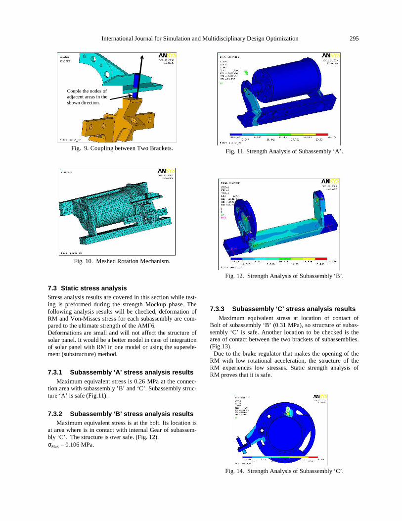
Bolt of subsystem ‘B’ is coupled with the internal gear of subsystem ‘C’ in the direction perpendicular to axis of rota-tion (Fig.9). Brackets of subsystems ‘A’, ‘B’ are coupled on the contact surface area between them in the direction per-pendicular to that area (Fig.7).
Apply loads that were calculated from solar panel simula-tion (using ANAYS) on the rotation subassembly (B) as shown in Fig.10. Apply displacement boundary condition (fix all degrees of freedom) on the subassembly ‘A’ along the two cylindrical area through which the subassembly is fixed to satellite body (Fig. 7).
Run Static analysis for strength analysis of each structure
of RM. Figure10 shows finite element model of RM.
Fig. 7. Boundary Conditions and Applied Loads.
Although the function of a mechanism is to release solar panel, it is also a structure, subject to all loading environ-ments that apply to other satellite structure components. So, we must predict loads and determine structural strength and life for all potentially critical events, satisfy stiffness requirements, and do environmental tests.
Fig. 8. Coupling between Internal Gear and Bolt.
Coupling nodes on two opposite areas in the shown direc-tion.
Locations of applied loads
Locations of fixed B.C. for all 6 DOF
International Journal for Simulation and Multidisciplinary Design Optimization 295
Fig. 9. Coupling between Two Brackets.
Fig. 10. Meshed Rotation Mechanism.
7.3 Static stress analysis Stress analysis results are covered in this section while test-ing is preformed during the strength Mockup phase. The following analysis results will be checked, deformation of RM and Von-Misses stress for each subassembly are com-pared to the ultimate strength of the AMГ6. Deformations are small and will not affect the structure of solar panel. It would be a better model in case of integration of solar panel with RM in one model or using the superele-ment (substructure) method.
7.3.1 Subassembly ‘A’ stress analysis results Maximum equivalent stress is 0.26 MPa at the connec-
tion area with subassembly ’B’ and ‘C’. Subassembly struc-ture ‘A’ is safe (Fig.11).
7.3.2 Subassembly ‘B’ stress analysis results Maximum equivalent stress is at the bolt. Its location is
at area where is in contact with internal Gear of subassem-bly ‘C’. The structure is over safe. (Fig. 12). σMax = 0.106 MPa.
Fig. 11. Strength Analysis of Subassembly ‘A’.
Fig. 12. Strength Analysis of Subassembly ‘B’.
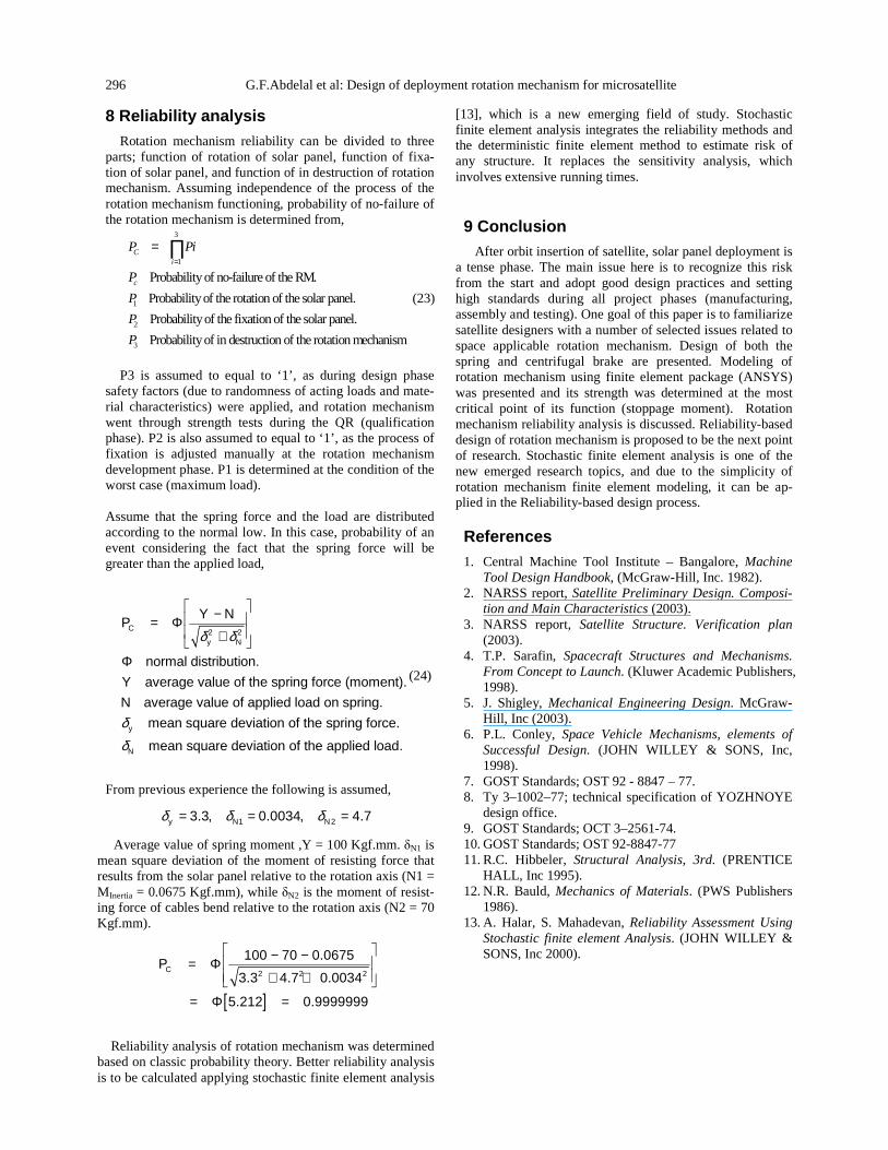
7.3.3 Subassembly ‘C’ stress analysis results Maximum equivalent stress at location of contact of
Bolt of subassembly ‘B’ (0.31 MPa), so structure of subas-sembly ‘C’ is safe. Another location to be checked is the area of contact between the two brackets of subassemblies. (Fig.13).
Due to the brake regulator that makes the opening of the RM with low rotational acceleration, the structure of the RM experiences low stresses. Static strength analysis of RM proves that it is safe.
Fig. 14. Strength Analysis of Subassembly ‘C’.
Couple the nodes of adjacent areas in the shown direction.
296 G.F.Abdelal et al: Design of deployment rotation mechanism for microsatellite
8 Reliability analysis Rotation mechanism reliability can be divided to three
parts; function of rotation of solar panel, function of fixa-tion of solar panel, and function of in destruction of rotation mechanism. Assuming independence of the process of the rotation mechanism functioning, probability of no-failure of the rotation mechanism is determined from,
3
1
1
2
3
Probability of no-failure of the RM.
Probability of the rotation of the solar panel.
Probability of the fixation of the solar panel.
Probability of in destruction of the rotation mechan
Ci
c
P Pi
P
P
P
P
=
= ∏
ism
(23)
P3 is assumed to equal to ‘1’, as during design phase
safety factors (due to randomness of acting loads and mate-rial characteristics) were applied, and rotation mechanism went through strength tests during the QR (qualification phase). P2 is also assumed to equal to ‘1’, as the process of fixation is adjusted manually at the rotation mechanism development phase. P1 is determined at the condition of the worst case (maximum load).
Assume that the spring force and the load are distributed according to the normal low. In this case, probability of an event considering the fact that the spring force will be greater than the applied load,
δ δ
δδ
− = Φ +
Φ
2 2
y
N
normal distribution.
Y average value of the spring force (moment).
N average value of applied load on spring.
mean square deviation of the spring force.
mean square deviation of t
C
y N
Y NP
he applied load.
(24)
From previous experience the following is assumed,
δ δ δ= = =1 23.3, 0.0034, 4.7y N N
Average value of spring moment ,Y = 100 Kgf.mm. δN1 is mean square deviation of the moment of resisting force that results from the solar panel relative to the rotation axis (N1 = MInertia = 0.0675 Kgf.mm), while δN2 is the moment of resist-ing force of cables bend relative to the rotation axis (N2 = 70 Kgf.mm).
[ ]
− − = Φ + +
= Φ =
2 2 2
100 70 0.0675
3.3 4.7 0.0034
5.212 0.9999999
CP
Reliability analysis of rotation mechanism was determined
based on classic probability theory. Better reliability analysis is to be calculated applying stochastic finite element analysis
[13], which is a new emerging field of study. Stochastic finite element analysis integrates the reliability methods and the deterministic finite element method to estimate risk of any structure. It replaces the sensitivity analysis, which involves extensive running times.
9 Conclusion After orbit insertion of satellite, solar panel deployment is
a tense phase. The main issue here is to recognize this risk from the start and adopt good design practices and setting high standards during all project phases (manufacturing, assembly and testing). One goal of this paper is to familiarize satellite designers with a number of selected issues related to space applicable rotation mechanism. Design of both the spring and centrifugal brake are presented. Modeling of rotation mechanism using finite element package (ANSYS) was presented and its strength was determined at the most critical point of its function (stoppage moment). Rotation mechanism reliability analysis is discussed. Reliability-based design of rotation mechanism is proposed to be the next point of research. Stochastic finite element analysis is one of the new emerged research topics, and due to the simplicity of rotation mechanism finite element modeling, it can be ap-plied in the Reliability-based design process.
References 1. Central Machine Tool Institute – Bangalore, Machine
Tool Design Handbook, (McGraw-Hill, Inc. 1982). 2. NARSS report, Satellite Preliminary Design. Composi-
tion and Main Characteristics (2003). 3. NARSS report, Satellite Structure. Verification plan
(2003). 4. T.P. Sarafin, Spacecraft Structures and Mechanisms.
From Concept to Launch. (Kluwer Academic Publishers, 1998).
5. J. Shigley, Mechanical Engineering Design. McGraw-Hill, Inc (2003).
6. P.L. Conley, Space Vehicle Mechanisms, elements of Successful Design. (JOHN WILLEY & SONS, Inc, 1998).
7. GOST Standards; OST 92 - 8847 – 77. 8. Ty 3–1002–77; technical specification of YOZHNOYE
design office. 9. GOST Standards; OCT 3–2561-74. 10. GOST Standards; OST 92-8847-77 11. R.C. Hibbeler, Structural Analysis, 3rd. (PRENTICE
HALL, Inc 1995). 12. N.R. Bauld, Mechanics of Materials. (PWS Publishers
1986). 13. A. Halar, S. Mahadevan, Reliability Assessment Using
Stochastic finite element Analysis. (JOHN WILLEY & SONS, Inc 2000).