
Thermal modeling of a cylindrical LiFePO4/graphite lithium-ion battery
Upload
independentCategory
view
5download
0
Journal of Power Sources 128 (2004) 292–307
Design and simulation of a lithium-ion battery with a phase changematerial thermal management system for an electric scooter
Siddique A. Khateeba, Mohammed M. Faridb, J. Robert Selmana, Said Al-Hallaja,∗a Center for Electrochemical Science and Engineering, Department of Chemical and Environmental Engineering,
Illinois Institute of Technology, Chicago, IL 60616, USAb Department of Chemical and Materials Engineering, University of Auckland, Auckland, New Zealand
Received 21 August 2003; accepted 27 September 2003
Abstract
A lithium-ion battery employing a novel phase change material (PCM) thermal management system was designed for an electric scooter.Passive thermal management systems using PCM can control the temperature excursions and maintain temperature uniformity in Li-ionbatteries without the use of active cooling components such as a fan, a blower or a pump found in air/liquid-cooling systems. Hence, theadvantages of a compact, lightweight, and energy efficient system can be achieved with this novel form of thermal management system.Simulation results are shown for a Li-ion battery sub-module consisting of nine 18650 Li-ion cells surrounded by PCM with a meltingpoint between 41 and 44◦C. The use of aluminum foam within the PCM and fins attached to the battery module were studied to overcomethe low thermal conductivity of the PCM and the low natural convection heat transfer coefficient. The comparative results of the PCMperformance in the presence of Al-foam and Al-fins are shown. The battery module is also simulated for summer and winter conditions.The effect of air-cooling on the Li-ion battery was also studied. These simulation results demonstrate the successful use of the PCM as apotential candidate for thermal management solution in electric scooter applications and therefore for other electric vehicle applications.© 2003 Elsevier B.V. All rights reserved.
Keywords:Lithium-ion battery; Thermal management; Phase change materials; Electric scooter; Thermal modeling/simulation; Air-cooling
1. Introduction
The automotive market demands high specific power andhigh specific energy density batteries to meet the operationalneeds of electric vehicles without adding substantial weightto the vehicle. Lead–acid batteries have served the batterymarket needs for more than a century in terms of crankingpower, life and low cost[1]. Lead–acid batteries face a toughchallenge to meet these criteria while advanced battery tech-nology such as nickel-metal hydride (NiMH) and lithium-ionbatteries have demonstrated superior performance comparedto lead–acid batteries.Table 1summarizes the characteris-tics of few commercially available rechargeable batteries. Asshown inTable 1, lithium-ion batteries have four to five timeshigher energy density than the lead–acid batteries, whichmakes them suitable for electric vehicles providing longerrange, sufficient acceleration and high calendar life[2]. Al-though, NiMH batteries is currently the battery of choice inhybrid electric vehicle (HEV), Li-ion battery has twice the
∗ Corresponding author. Tel.:+1-312-567-5118; fax:+1-312-567-6914.E-mail address:[email protected] (S. Al-Hallaj).
energy density of NiMH battery and if the thermal safetyissue is successfully addressed, Li-ion batteries have the po-tential to replace the NiMH battery for HEV applications.
In order to achieve the power demand in electronics orpropulsion power in an electric vehicle, a number of Li-ioncells have to be connected in series and parallel to form abattery pack. Hence, the safety of the battery pack and elec-tric vehicle apart from the user becomes a big concern owingto their higher volumetric heat generation rate as comparedto valve-regulated lead–acid (VRLA) or NiMH battery[3]. Hence, effective heat dissipation and thermal runawaysafety are the major concerns in the commercialization ofLi-ion batteries for high power applications. Therefore, asuccessful thermal management solution is required. Thereexists a strong interdependence between the temperaturedistribution within the battery and electrochemical perfor-mance[4], which would require a proper thermal man-agement system for optimal performance of these batterypacks. Consequently, temperature uniformity and heat dis-sipation are important factors in the development of thermalmanagement systems for Li-ion batteries. An ideal thermalmanagement system should be able to maintain the batterypack at an optimum temperature with small variations within
0378-7753/$ – see front matter © 2003 Elsevier B.V. All rights reserved.doi:10.1016/j.jpowsour.2003.09.070

S.A. Khateeb et al. / Journal of Power Sources 128 (2004) 292–307 293
Nomenclature
mPCMmass of the PCM (kg)Cp specific heat of the PCM (J/(g K))Cpe effective specific heat of the PCM ((J/(g K))Tm PCM melting point (K)Ti PCM initial temperature (K)λ latent heat of the PCM (kJ/kg)QdischLi-ion battery discharge heat (kJ)
the modules and within the pack and also meet the other re-quirements namely compact, light-weight, easy packaging,inexpensive, low parasitic power demand features.[3].
Conventional heat dissipation methods such as forcedair-cooling and liquid-cooling have been extensively devel-oped as thermal management tools for electric vehicles. Suchthermal management systems may prove to be effective butthey tend to make the overall system too bulky, complex andexpensive in terms of blower, fans, pumps, pipes and otheraccessories, which add on to the system weight and parasiticpower requirements[3].
A novel thermal management solution, which uses phasechange material (PCM) as a heat dissipation source, wasproposed for electric and hybrid electric vehicle applications[6]. The major advantages for such a thermal managementsystem are a compact, inexpensive, low maintenance systemwith no parasitic power requirements. A Li-ion battery sys-tem for electric vehicle applications such as electric bikes,electric two to four wheeled scooter, electric cars and hy-brid electric vehicles requires a well-designed thermal man-agement system with a reliable safety circuit design. In thispaper, a Li-ion battery design with a PCM thermal manage-ment system is presented and simulated for a Zappy electricscooter model no. 02815B (ZAP, Santa Rose, CA). Resultsshow that a PCM thermal management system appears to bean ideal thermal management solution for electric scootersgiven the vehicle space constraints and absence of auxiliarypower sources.
Table 1Characteristics of the rechargeable batteries[5]
NiMH Lead–acid Li-ion Li-ion polymer
Gravimetric energy density (Wh/kg) 60–120 30–50 110–160 100–130Internal resistance (includes peripheral circuits) (mW) 200–300, 6 V pack<100, 12 V pack 150–250, 7.2 V pack 200–300, 7.2 V packCycle life (to 80% of initial capacity) 300–500 200–300 500–1000 300–500Fast charge time 2–4 h 8–16 h 2–4 h 2–4 hOvercharge tolerance Low High Very low LowSelf-discharge/month (room temperature) 30% 5% 10% ∼10%Cell voltage (nominal) 1.25 V 2 V 3.6 V 3.6 VLoad current
Peak 5 C 5 C >2 C >2 CBest result 0.5 C or lower 0.2 C 1 C or lower 1 C or lower
Operating temperature (discharge only) −20 to 60◦C −20 to 60◦C −20 to 60◦C 0–60◦CMaintenance requirement 60–90 days 3–6 months Not required Not requiredCommercial use since 1990 1970 1991 1999
Table 2Specifications of Zappy electric scooter model no. 02815 (source: ZappyTechnical Manual[7])
Features Specifications
Operating voltage 12 V dcBattery Sealed, maintenance free lead–acid batteryBattery dimension 7 in.× 7 in. × 3 in.Battery weight 12.5 lbs (5.7 kg)Speed 11–13 mph (17.7–20.9 km/h)Driving range 8 milesa
Motor Permanent magnet direct current motorMotor power 0.5 hp at 3500 rpm peakMotor control Single speed, solid
state/electro-mechanical systemDrive train Silent belt driveBrakes Rear band brake, hand operatedOverall dimension Length: 41 in.; width: 11 in.; height: 11 in.Overall weight 37 lbs (16.8 kg)
a On level ground, depends on the rider’s weight and road inclination.
The Zappy electric scooter is a lightweight, foldable elec-tric scooter powered by a 12 V, 18 Ah lead–acid battery. Thespecifications of the Zappy electric scooter are summarizedin Table 2.
Fig. 1(a)shows the Zappy electric scooter in the foldedview andFig. 1(b) shows its full view. The electric motoris located at the rear end and the battery is situated at thebottom as shown in the figure.
2. Development of Li-ion battery for the Zappy electricscooter
The detailed outline in developing the Li-ion battery maybe summarized as follows.
2.1. Performance evaluation of the electric scooter
This test was conducted to verify the manufacturer’s spec-ifications for the electric scooter. Various parameters suchas the mileage, speed, battery charge/discharge time were

294 S.A. Khateeb et al. / Journal of Power Sources 128 (2004) 292–307
Fig. 1. (a) and (b) Zappy electric scooter model no. 02815B (source:Zappy Technical Manual[5]).
determined under different operating conditions such as vari-ation in the load, level and inclined road conditions.
From these tests, it was concluded that the Zappy elec-tric scooter did not meet the performance specifications setby the manufacturer; however, these results have to be veri-fied with few more scooters. The average speed was around8 mph (13 km/h) with a medium and heavy weight rider ona level ground; the driving range was about 5 miles (8 km)for a fully charged battery. These tests were performed withvarying loads and different road conditions. The averagecharging time of the lead–acid battery was around 8 h. Fromthis test, the performance limits of the electric scooter wereset and will be used for comparison with the Li-ion battery.
Fig. 2. Preliminary testing of Zappy electric scooter.
2.2. Electrical characterization test
This test is carried out in order to determine the size ofthe battery needed to meet the power requirements. Thevoltage–current characteristics of the battery and the electricmotor characteristics were obtained by using an onboard dataacquisition system (DAQ). Various time-series data wererecorded by the DAQ system such as the current, voltageand the motor temperature.
Fig. 2 shows the results obtained from the test run of theZappy scooter on a relatively flat ground with small inclineswith rider weighing 145 lbs (65 kgs).
The following conclusions were drawn based on the pre-liminary vehicle test results:
• the surge current during the start-up of the electric motorwas around 50–55 A;
• the average current during the scooter operation on a flatground was found to be 18–24 A, which is the currentrating of the present lead–acid battery in the Zappy electricscooter;
• the current requirements of the battery during an uphillcan easily reach 60 A;
• the temperature of the lead–acid battery remains between20 and 30◦C;
• the temperature of the electric motor rises to 70◦C froma start temperature of 20◦C.
Since the temperature rise of the lead–acid battery isnot significant as compared to NiMH and Li-ion battery,the lead–acid battery does not require a thermal manage-ment system in this electric scooter. In lead–acid battery, thedischarge reaction of the battery is not highly exothermic
S.A. Khateeb et al. / Journal of Power Sources 128 (2004) 292–307 295
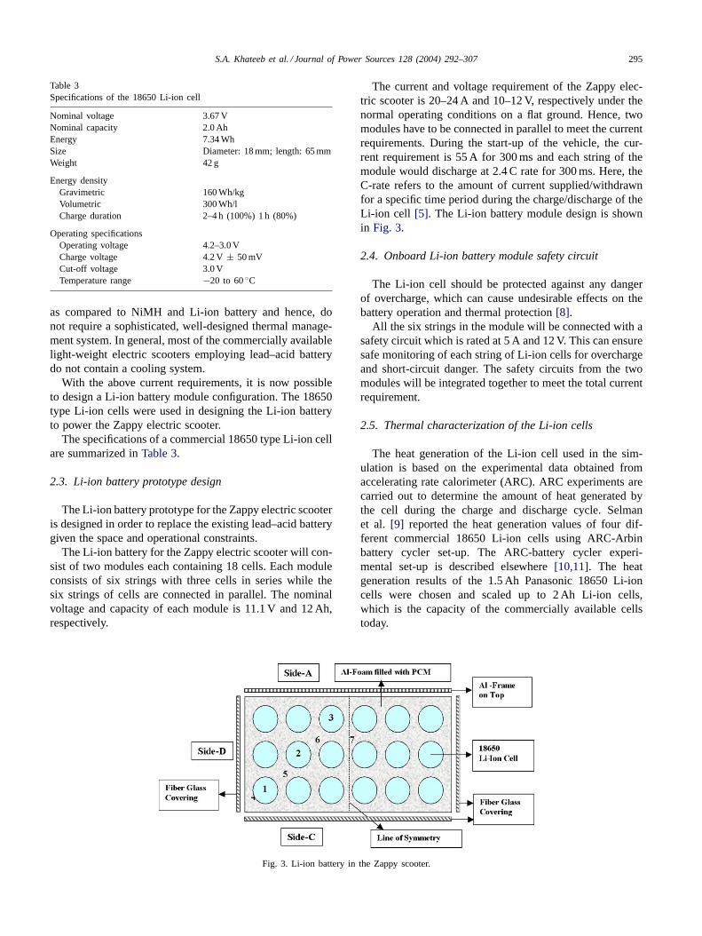
Table 3Specifications of the 18650 Li-ion cell
Nominal voltage 3.67 VNominal capacity 2.0 AhEnergy 7.34 WhSize Diameter: 18 mm; length: 65 mmWeight 42 g
Energy densityGravimetric 160 Wh/kgVolumetric 300 Wh/lCharge duration 2–4 h (100%) 1 h (80%)
Operating specificationsOperating voltage 4.2–3.0 VCharge voltage 4.2 V± 50 mVCut-off voltage 3.0 VTemperature range −20 to 60◦C
as compared to NiMH and Li-ion battery and hence, donot require a sophisticated, well-designed thermal manage-ment system. In general, most of the commercially availablelight-weight electric scooters employing lead–acid batterydo not contain a cooling system.
With the above current requirements, it is now possibleto design a Li-ion battery module configuration. The 18650type Li-ion cells were used in designing the Li-ion batteryto power the Zappy electric scooter.
The specifications of a commercial 18650 type Li-ion cellare summarized inTable 3.
2.3. Li-ion battery prototype design
The Li-ion battery prototype for the Zappy electric scooteris designed in order to replace the existing lead–acid batterygiven the space and operational constraints.
The Li-ion battery for the Zappy electric scooter will con-sist of two modules each containing 18 cells. Each moduleconsists of six strings with three cells in series while thesix strings of cells are connected in parallel. The nominalvoltage and capacity of each module is 11.1 V and 12 Ah,respectively.
Fig. 3. Li-ion battery in the Zappy scooter.
The current and voltage requirement of the Zappy elec-tric scooter is 20–24 A and 10–12 V, respectively under thenormal operating conditions on a flat ground. Hence, twomodules have to be connected in parallel to meet the currentrequirements. During the start-up of the vehicle, the cur-rent requirement is 55 A for 300 ms and each string of themodule would discharge at 2.4 C rate for 300 ms. Here, theC-rate refers to the amount of current supplied/withdrawnfor a specific time period during the charge/discharge of theLi-ion cell [5]. The Li-ion battery module design is shownin Fig. 3.
2.4. Onboard Li-ion battery module safety circuit
The Li-ion cell should be protected against any dangerof overcharge, which can cause undesirable effects on thebattery operation and thermal protection[8].
All the six strings in the module will be connected with asafety circuit which is rated at 5 A and 12 V. This can ensuresafe monitoring of each string of Li-ion cells for overchargeand short-circuit danger. The safety circuits from the twomodules will be integrated together to meet the total currentrequirement.
2.5. Thermal characterization of the Li-ion cells
The heat generation of the Li-ion cell used in the sim-ulation is based on the experimental data obtained fromaccelerating rate calorimeter (ARC). ARC experiments arecarried out to determine the amount of heat generated bythe cell during the charge and discharge cycle. Selmanet al. [9] reported the heat generation values of four dif-ferent commercial 18650 Li-ion cells using ARC-Arbinbattery cycler set-up. The ARC-battery cycler experi-mental set-up is described elsewhere[10,11]. The heatgeneration results of the 1.5 Ah Panasonic 18650 Li-ioncells were chosen and scaled up to 2 Ah Li-ion cells,which is the capacity of the commercially available cellstoday.
296 S.A. Khateeb et al. / Journal of Power Sources 128 (2004) 292–307
2.6. Simulation of the Li-ion battery module
The Li-ion battery module consists of 18 cells arrangedin three rows with six cells in each row as shown inFig. 3.Two battery modules are placed adjacent to each other inthe Zappy electric scooter in such a way that each modulerests on one of its longer sides, side C. When the scooter ismoving, the side edges of the battery are exposed to forcedair circulation. The battery compartment is made up of fiber-glass on three sides and covered on top by the aluminumscooter frame. Side A is assumed to be in close contact withthis frame and the bottom side C and other sides B and Dare also assumed to be in close contact with the fiberglass.
A single sub-module containing nine cells was simulatedbecause of the symmetry in arrangement of the cells andsimilar boundary conditions of the battery. Forced coolingwas assumed to take place on three sides (A, C and D) of thebattery during the discharge of the battery module when thescooter is moving and adiabatic condition along the otherside (line of symmetry). The heat transfer coefficient dur-ing forced cooling was calculated to be 20 W/(m2 K) usinga heat transfer correlation available in literature[12]. Dur-ing the battery charge, when the scooter has stopped onlyfree convection cooling is assumed to take place on the threesides of the module (A, C and D). The heat transfer coeffi-cient during free or natural convection was considered to be5 W/(m2 K) [12]. The simulations are carried out for con-tinuous three cycles representing the most abusive batteryoperation.
It is assumed that the battery box surfaces are in closecontact with the battery compartment sides in the presentZappy scooter design. The existing battery design and itsorientation in the battery compartment can replace the exist-ing lead–acid battery in the Zappy scooter without makingany design changes. Modifications to the battery compart-ment have to be made in an alternative design to incorporatethe aluminum fins on the battery compartment.
The initial temperature of the Li-ion battery module wasassumed to be 30◦C in the simulations, except during thesummer and winter conditions where the initial temperaturewas 40 and 0◦C, respectively.
2.7. Modeling and simulation of the Li-ion battery modulewith air-cooling thermal management system
A simplified unsteady-state two-dimensional thermalmodel [2] was employed for simulating the Li-ion celloperation. The simulations were conducted for three dis-charge/charge cycles to verify the thermal stability of thebattery module.
The sub-module shown inFig. 3 is simulated to under-stand the thermal effect of the module during the batteryoperation with air-cooling. The air flowing in between theLi-ion cells is assumed to be in natural convection with aheat transfer coefficient of 5 W/(m2 K) [12], since the boxis covered completely on all sides. Also, the space available
for the battery in the scooter is constrained which makes itdifficult to accommodate any kind of air-flow passage, duct-ing, fans that may be required for forced air-cooling of themodule.
In the Zappy electric scooter, there exists an aluminumframe casing, which covers the electric motor and the batterybox, as shown inFig. 1. There is a close contact between thebattery box and the aluminum frame, which can dissipatethe heat during the battery discharge. This aluminum frameincreases the heat transfer area available for heat dissipation.In order to show the benefit of this large heat transfer areaon heat dissipation rate, the sub-module is simulated withaluminum fins attached on the external sides of the batteryspace provided in the Zappy scooter.
The temperature profiles of the Li-ion cell and the sur-rounding air are shown inFig. 4. The temperature of theLi-ion cell at center location (3) rises by 45◦C whereas thecell exposed to forced air-cooling during discharge at loca-tion (1) (inFig. 3) rises by 35◦C, with a temperature gradientof 10◦C between the cells. There also exists a large temper-ature gradient of about 20◦C between the air at the center ofthe module and the air exposed to forced air-draft convectionat the outer location. Such thermal gradients within a bat-tery module can result in unequal charge/discharge capacityof the individual cells over the cycle life. Wright et al.[20],conducted several experiments with Li-ion cells exposed tovarious temperatures and showed that the cell capacity de-grades significantly affecting the calendar life when exposedto a temperature >60◦C. Also, the onset of the thermal run-away reaction of the Li-ion cells starts in the temperaturerange of 70–100◦C depending on the electrolyte composi-tion and electrode material[13]. As a result, the Li-ion cellin this case is prone to a thermal runaway risking the safetyof the battery and vehicle.
In order to reduce the temperature rise of the Li-ion cells,the heat transfer coefficient of the surrounding air has tobe increased significantly, which can be achieved only viaforced air-cooling which adds to complexity in design in-corporating fans if needed, ducting and other accessories.All these features require major modifications in the existingscooter. But even with forced air-cooling, external power isrequired to keep the cooling system operational which raisesa question of safety risk in case of external power break-down or mechanical failure of any of its components.
2.7.1. The need for a passive thermal management systemAn especially difficult problem that must be addressed by
an active cooling system is the battery temperature rise whenthe vehicle is parked on a hot day. Nelson et al.[14] analyzedthe consequences of a battery temperature rise of up to 45◦Cin the absence of active cooling when the vehicle is turnedoff. Under such circumstances, starting the car again canresult in the battery temperature exceeding safe limits. Theyshowed that a dedicated refrigeration system is necessary tokeep the battery at close to ambient temperatures during thewarm summer months. Increasing the amount of insulation

S.A. Khateeb et al. / Journal of Power Sources 128 (2004) 292–307 297
Fig. 4. Temperature rise of the Li-ion cells and air (h = 5 W/(m2 K)).
around the battery was considered, but this increases designcomplexity and adds further parasitic power requirementswhen the vehicle is turned off.
On the other hand, this problem can be solved relativelysimply without any additional power requirement by a pas-sive thermal management system via phase change materialintegrated cooling system (with proper PCM mass and tem-perature optimization). It is not suggested that active cool-ing is completely unnecessary when using PCM integratedcooling. But the design and control of the active compo-nent is much simplified. However, to achieve this simplicity,PCM integration has to be considered from the outset. Inour opinion, retrofitting will not work.
Recently, EV Global Motors Co., which manufactureselectric scooters with Li-ion batteries recalled 2000 Li-ionbatteries in Mini E-bike electric bicycles, after it receivedfive reports of battery over-heating, three of which caughtfire [15]. The main reason for this incident was the ab-
Table 4Properties of paraffin wax[6]
Melting temperature 40–44◦CLatent heat 195 KJ/kgSpecific heat capacity 1.77 KJ/kg K
Thermal conductivitySolid phase 0.21 W/m KLiquid phase 0.29 W/m K
DensitySolid phase 822 kg/m3
Liquid phase 910 kg/m3
sence of a thermal management system for the Li-ion batter-ies. The Li-ion battery in this case depended on the naturalair-cooling of the battery alone for heat dissipation, whichproved to be disastrous because of insufficient cooling.
Nelson et al. [14] discuss the disadvantages of anair-cooling system in detail for Li-ion batteries for hy-brid electric vehicle applications. They concluded thatair-cooling system requires high power because of thelarge volume of air required at low speed, as well as largecross-sections in the flow passages from and to the supplyand exit manifolds. Also, parallel air-flow channels must beprovided to all modules, which further complicates designand wastes battery power. Liquid-cooling, which has not
Table 5Specifications of the Li-ion battery module with PCM system for Zappyelectric scooter
Specifications Value
No. of modules 2No. of 18650 Li-ion cells per module 18Weight of the cells 756 gVolume of the cells 297 cm3
Weight of the PCM 216 gVolume of the PCM 237 cm3
Weight of Al-foam, safety circuits,battery box (approximately)
250 g
PCM/battery weight ratio 28.6%PCM/battery volume ratio 79.7%Dimensions of the battery box Length: 15 cm; width:
7.8 cm; height: 7.5 cmTotal weight of the Li-ion
battery/module1.2 kg (2.7 lbs)
298 S.A. Khateeb et al. / Journal of Power Sources 128 (2004) 292–307
yet been introduced anywhere, may allow smaller coolingflow cross-sections, but barely yield a reduction in massflow rates and cooling channel mass.
Toyota Prius employs a sophisticated air-cooling thermalmanagement for the NiMH batteries (whose heat generation
Fig. 5. (a) Temperature contours of Li-ion cells and PCM. (b) Temperature rise of Li-ion cells and PCM. (c) Effective specific heat of PCM.
is much less than that of Li-ion batteries)[16]. The controlstrategy employed in the Toyota Prius forces the NiMH bat-tery to utilize only part of its power capability and about 40%of the total charge of the battery, thus sacrificing the bat-tery capacity and power for longer cycle life and to control

S.A. Khateeb et al. / Journal of Power Sources 128 (2004) 292–307 299
Fig. 5. (Continued).
the temperature rise due to specific thermal and mechanicaldesign constraints of the air-cooling system.
Implementing a PCM thermal management system canavoid the above-mentioned disadvantages of the air-coolingsystem, limited battery capacity and power use with awell-designed optimized PCM system. The thermal re-sponse of the Li-ion battery in the presence of a PCM willbe explored in the next few sections.
2.8. Phase change material (PCM) thermal managementsystem design
Based on the heat generation data from the ARC results[9], the mass of the PCM required is calculated as follows:
heat discharged by the battery
= sensible heat of the PCM+ latent heat of the PCM
Qdisch = m∗PCMC∗
p(Tm − Ti) + m∗PCMλ (1)
The properties of the Paraffin wax used as a PCMfor Li-ion batteries thermal management are as shown inTable 4.
The quantity of the PCM required was calculated to beapproximately 12 g for each 18650 Li-ion cell. Hence, for aLi-ion battery module consisting of 18 cells, the total massof the PCM is 216 g. The specifications of the Li-ion batteryprototype are summarized inTable 5.
Another issue to be addressed with the PCM system isthe volume expansion encountered upon solidification of thePCM after melting, which can induce mechanical stress onthe battery pack casing. This was accounted for in the batterydesign by allowing an additional 10% volume in the battery
pack casing. Also, the battery casing has to be completelyleak-proof to avoid any possible leaks of the PCM when itis in the liquid phase.
3. Modeling and simulation results for the phasechange material thermal management system
A simplified unsteady-state two-dimensional thermalmodel [2] was employed for simulating the Li-ion cell op-eration. The PCM was modeled using an effective heat ca-pacity method as explained elsewhere[17]. The simulationswere conducted for three discharge/charge cycles to verifythe thermal stability of the battery module. The temperaturerise of the Li-ion cells and PCM shown in simulation are atthe numbered locations shown inFig. 3.
3.1. Analysis of the effective specific heat curves insimulation
The effective specific heat (Cpe) accounts for the latentheat, in the phase change region which gives an indicationof the extent of melting and solidification of the PCM. Thevalues ofCpe change from a small value of the solid phaseto a maximum value of the order of a hundred or less at themelting temperature[17]. Rising peaks in the effective spe-cific heat curves of the PCM show the transition from thesolid phase to the mushy phase during the discharge of thebattery. Higher values of the effective specific heat (1.77 <
Cpe < 130) denote the latent heat of melting/solidificationof the PCM; the higher the peaks, the greater the extent ofmelting. Smaller peaks in the curves signify little melting of

300 S.A. Khateeb et al. / Journal of Power Sources 128 (2004) 292–307
Fig. 6. (a).Temperature contours of Li-ion cells and PCM in Al-foam. (b) Temperature rise of Li-ion cells and PCM in Al-foam. (c) Effective specificheat of PCM in Al-foam.

S.A. Khateeb et al. / Journal of Power Sources 128 (2004) 292–307 301
Fig. 6. (Continued).
the PCM. When the PCM has completely melted, the peaksdrop down showing the transition from the mushy phase tothe liquid phase. During the rest period when the tempera-ture of the Li-ion cells and the PCM drops, the PCM changesinto the mushy phase again, represented by a broad peak.The width of the peaks during the melting and solidifica-tion stages signifies the time length of the PCM transitionfrom solid-mushy phase (melting-battery discharge period)and liquid-mushy phase (solidification-battery rest/chargeperiod), respectively. Usually, the width of the peaks is nar-row during the PCM melting when the battery is dischargingand broad during solidification of PCM under the batteryrest/charge condition.
3.2. Case study 1
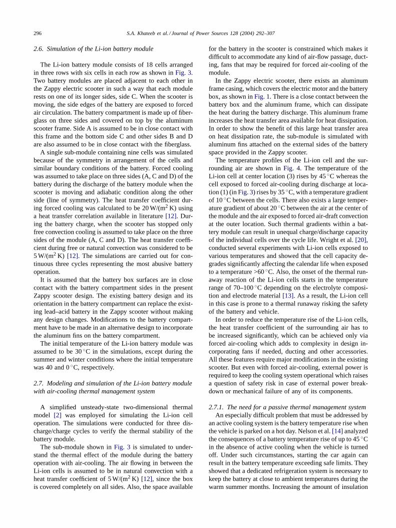
3.2.1. Li-ion battery module with PCM aloneFig. 5(a)shows the temperature contours of the module
at the end of the third discharge cycle. InFig. 5(a), one sideis modeled as perfectly insulated (due to line of symmetry)and the other three sides (A, C and D) are subjected toforced cooling when the scooter is moving. As seen fromthe module arrangement, the cell at the center of the moduleexperiences the highest temperature rise compared to theother cells as indicated inFig. 5(a). The non-uniformity intemperature distribution of the Li-ion cells and the PCM inthe module is clearly represented by the different contoursshown inFig. 5(a).
The temperature distribution of the cells and the PCMduring the three cycles is shown inFig. 5(b). The scooter
is assumed to stop after 1 h of use for the battery to becharged. The normal charging period for the Li-ion batter-ies is usually 2–4 h[9]. During this period, cooling of thebattery is assumed to occur by natural convection cooling.In the first cycle of discharge, complete melting takes placeat the center location (7) with only partial melting at loca-tion (5) and very little melting at location (4) exposed toforced air-draft cooling during discharge; these locationsare shown inFig. 3. During the following charge period,the post-discharge heat evolution from the cells causes thetemperature of the PCM increases slightly whereas thetemperature of the cells keeps decreasing. But due to poorthermal conductivity of the PCM, the PCM at locations (5)and (7) remain in the mushy phase at the end of the firstcycle whereas the PCM at location (4) solidifies due to littlemelting experienced during discharge.
During the second and the third discharge cycles, thePCM at the inner locations are in the mushy phase at thebeginning, which causes the temperature of the cells and thePCM to increase significantly. The latent heat of the PCMis completely utilized during the pre-discharge period re-sulting in complete melting of PCM at inner locations turn-ing them into liquid phase. The temperature of the cellsstarts rising along with the liquid PCM.Fig. 5(c)shows theeffective specific heat profiles of the different PCM loca-tions. The PCM at locations (5) and (7) show peaks duringthe three cycles indicating their melting and solidificationduring discharge and charge cycles. The PCM at the outerend of the module exposed to forced air-convection dur-ing discharge starts melting during the third discharge cycle

302 S.A. Khateeb et al. / Journal of Power Sources 128 (2004) 292–307
Fig. 7. (a) Temperature contours of Li-ion cells and PCM in Al-foam with Al-fins. (b) Temperature rise of Li-ion cells and PCM in Al-foam with Al-fins.(c) Effective specific heat of PCM in Al-foam with Al-fins.

S.A. Khateeb et al. / Journal of Power Sources 128 (2004) 292–307 303
Fig. 7. (Continued).
indicated by the small peak with no peaks during the previ-ous cycles.
Hence, the effect of the poor thermal conductivity of thePCM is evident, resulting in non-uniform temperature dis-tribution in the module and ineffective heat dissipation. Theperformance of the Li-ion cell is strongly dependent on thetemperature, which affects its cyclic capability and capacityretention. Li-ion cells exposed to higher temperature can re-sult in higher capacity fade and faster aging[16], resultingin an imbalance in terms of charge acceptance and dischargecapability of the cells in the module. As a measure of improv-ing the thermal performance of the phase change material,the effect of the encapsulating the PCM in aluminum-foamin studied in the next section.
3.3. Case study 2
3.3.1. PCM with Al-foamIn this simulation, the poor thermal conductivity of the
PCM is overcome by using aluminum foam. Commerciallyavailable Duocel aluminum foam with a density of 8–10%and 40 ppi (pores per inch) was used for this purpose[18].The aluminum foam used enhances the thermal conductiv-ity of the PCM approximately by one order of magnitude orgreater. The effective thermal conductivity, which accountsfor the combined conduction through the aluminum foammaterial and the PCM, which fills up the voids, was calcu-lated to be approximately 3 W/(m2 K) [19].
Fig. 6(a) and (b)clearly show the uniform temperaturedistribution throughout the entire PCM and the cells ascompared toFig. 5(a) and (b), due to the encapsulation ofthe PCM in the Al-foam.Fig. 6(a)shows the temperaturecontours of the module. There are no multiple temperature
interface boundaries between cell–PCM and PCM–PCMsimilar to that shown in the previous case for PCM alone(i.e. Fig. 5(a)). The role of the aluminum foam in fast heatdissipation can be observed inFig. 6(b). After the first dis-charge cycle of the battery, the PCM is completely meltedin the module similar to the previous case but solidificationof the PCM occurs during the charge/rest period. In the sec-ond discharge cycle, the temperature of the module beginsat 8◦C higher than the first cycle. Although the temperaturerise is almost same as the first discharge cycle, more latentheat of the PCM is utilized. In the third discharge cycle, theinitial temperature of the module is close to the melting pointof the PCM. The temperature rise is relatively same com-pared to the previous cycles because the latent heat of thePCM is utilized more at the beginning of discharge period.
The effective specific heat curves inFig. 6(c) indicatethe uniform melting and solidification of the PCM duringthe three cycles. Although, the addition of aluminum foamcreated a uniform temperature distribution in the moduleand a stable thermal response of the PCM as compared tothe previous case, it is desired to operate each dischargecycle from the same initial temperature operating condition.The next simulation study demonstrates the effect of addingaluminum fins to achieve this goal.
3.4. Case study 3
3.4.1. PCM with Al-foam and Al-finsThis conceptual design incorporating aluminum fins is
suggested as an alternative design of the existing Zappyscooter design. In the previous case study, the thermal re-sponse of the Li-ion cells and the PCM was not stablein the consecutive cycles, resulting in a different starting

304 S.A. Khateeb et al. / Journal of Power Sources 128 (2004) 292–307
Fig. 8. (a) Temperature contours of Li-ion cells and PCM during summer. (b) Temperature rise of Li-ion cells and PCM during summer. (c) Effectivespecific heat of PCM during summer.

S.A. Khateeb et al. / Journal of Power Sources 128 (2004) 292–307 305
Fig. 8. (Continued).
temperature during each cycle. The addition of aluminumfins on the external surface of the module can overcome thisproblem as explained below.
The temperature contours of the module is shown inFig. 7(a), depicting the uniform temperature distributionbecause of the combined effect of the aluminum foam andfins. Fig. 7(b) shows the thermal response of the mod-ule with a stable temperature profile of the cells and thePCM as compared toFig. 6(b). The PCM undergoes com-plete solidification during the charge/rest period due to theinclusion of aluminum-fins, which boosts the heat dissipa-tion rate from the cells and the PCM when compared toaluminum foam alone. The PCM undergoes little meltingduring all of the discharge cycles by observing the narrowpeaks inFig. 7(c), indicating that a large latent heat is stillavailable.
From these simulation results, it can be understood thatthe thermal stability of the entire module requires the ad-dition of aluminum-fins in addition to the aluminum foam.Since our main objective is to replace the existing lead–acidbattery with minimal changes in the scooter design, the ad-vantages of the Al-fins can be realized with the presence ofthe Al-frame covering the battery as shown inFig. 1, whichwas not considered in the simulations. Because of its largeheat transfer area available, the Al-frame can act as extendedheat transfer surfaces for dissipating the heat.
Another important conclusion from this simulation is theavailability of the latent heat of the PCM. This can prove tobe an effective reserve heat sink in case of a higher ambienttemperature or in the event of the battery abuse caused bymechanical crushing or short-circuit, which can result in athermal runaway situation of the Li-ion cells.
3.5. Case study 4
3.5.1. Performance of the Li-ion battery during thesummer and winter conditions
In the previous simulations, the starting temperature ofthe PCM was assumed to be 30◦C and the temperaturerise shown was for this reference temperature. In order toevaluate the adaptability of the PCM to varying climaticconditions, the simulation is performed for the summer andwinter ambient temperatures. Since the thermal responseof the module is more effective only with the presence ofAl-foam and Al-fins, the simulation results are presentedfor this case alone.
During summer, the reference temperature is chosen tobe 40◦C. Hence, as soon as the battery starts discharging,the PCM begins melting and it is very interesting to observethe behavior of the PCM during all the three cycles. Thetemperature profiles of the Li-ion cells and the PCM regionis shown inFig. 8(a) and (b). In the first discharge cycle,most of the PCM is melted with maximum utilization of thelatent heat, resulting in a temperature rise of 4.5◦C. Duringthe following charge/rest period, the PCM does not recoverto its original solid phase and stays in the mushy phase atthe end of rest period.
The second discharge cycle begins with immediate uti-lization of the latent heat of the PCM, which regulates thetemperature of the Li-ion cells to a minimal increase. Butas soon as the PCM turns into a liquid phase, the tempera-ture of the Li-ion cells and the PCM increase significantlyas the PCM no more acts a heat sink with the temperaturerising by 9◦C. The Li-ion cells and the PCM show similarthermal response during the third discharge cycle with the

306 S.A. Khateeb et al. / Journal of Power Sources 128 (2004) 292–307
Fig. 9. Temperature rise of Li-ion cells and PCM during winter.
temperature rise of 11◦C at the end of discharge. Hence, themodule is expected to be within the safe temperature oper-ating limits in summer which cannot be achieved in the caseof an air-cooling system or using PCM alone.
The winter condition was simulated with an initial tem-perature of 0◦C and the temperature rise is reported with thisreference temperature. In this case, only the sensible heatof the PCM is utilized with no melting taking place as seenin Fig. 9. The thermal response of the module is repetitiveover all the three cycles.
It should be noted that the electrochemical performance ofthe Li-ion cells drops at low and elevated temperatures[8].For simplification purposes, in the above simulations undersummer and winter conditions, the temperature effects onthe Li-ion cell capacity were neglected and the performanceof the Li-ion cell was not altered as compared to the previoussimulation.
From the above simulation case studies, the phase changematerial clearly demonstrates the possibility of achievingan efficient thermal regulation of the Li-ion battery via asimple, inexpensive passive thermal management system.
4. Conclusions
A detailed design procedure of a Li-ion battery contain-ing PCM for thermal management was shown. The thermalresponse of the Li-ion battery module with air-cooling wasevaluated in the presence of Al-fins. The simulation resultsshowed that the Li-ion module was prone to thermal run-away due to inadequate air-cooling. Alternatively, the Li-ionbattery can be operated safe only with forced air-cooling,
adding to design complexity, addition of many componentsneeded for forced air-cooling and major modifications of theexisting scooter.
Simulation results of the Li-ion battery module employ-ing PCM alone indicated that the heat dissipation capabilityof the PCM is ineffective due to its poor thermal conductiv-ity; furthermore it may cause thermal runaway. The thermalperformance of the PCM was significantly improved by theaddition of aluminum foam, which increased the thermalconductivity of PCM by one order of magnitude. Thoughthe addition of aluminum foam decreased the temperaturerise of the Li-ion battery module by 25◦C, it proved to beineffective when the electric scooter is driven for continuousthree cycles due to the PCM completely melting during thesecond cycle, risking the battery module to high temperaturerise and thermal runaway. Aluminum fins were added to theexisting battery module to overcome this problem. Numer-ous simulations were conducted to obtain a stable tempera-ture profile of the Li-ion battery module by optimizing thelength and the number of fins. The aluminum fins proved tobe very effective in maintaining the temperature uniformityand suppressing the temperature rise during the three cy-cles of scooter operation. During the summer operation, theLi-ion battery module showed a temperature rise of 25◦Cstarting with 40◦C initial temperature, which reflects a safetemperature situation for the Li-ion battery module. Therewas no melting of the PCM under the winter operating con-ditions with a start temperature of 0◦C.
In this work, the modeling and the simulation work did notconsider the thermal runaway effects during the abuse oper-ating conditions of the Li-ion battery. Future work will incor-porate these simulations and also include the experimental

S.A. Khateeb et al. / Journal of Power Sources 128 (2004) 292–307 307
validation of the simulation results presented. The presentLi-ion battery design and battery orientation is suggested inorder to replace the existing lead–acid battery in the Zappyelectric scooter with the Li-ion battery without introducingany mechanical changes in the battery compartment. But analternative design will feature the aluminum fins on the bat-tery compartment and include modification of the batterycompartment to accommodate the Li-ion battery with thePCM system for best heat dissipation effects.
These simulation results prove the feasibility of awell-designed phase change material system as a simple,cost effective thermal management solution for Li-ion bat-teries in all applications including hybrid electric vehicle.
Acknowledgements
The authors are grateful for the financial support providedby All Cell Technologies, LLC (Chicago, IL) and the ITECgroup (Chicago, IL). Technical support by MicroSun Tech-nologies is also acknowledged. The authors thank AndrewMills for his help in formatting the paper.
References
[1] R.F. Nelson, J. Power Sources 107 (2002) 226–239.[2] S. Al-Hallaj, H. Maleki, J.S. Hong, J.R. Selman, J. Power Sources
83 (1999) 1–8.[3] A.A. Pesaran, in: Proceedings of the first Annual Advance Auto-
mobile Battery Conference, 5–8 February 2001.http://www.ctts.nrel.gov/BTM.
[4] M. Sung, K.H. Liu, Y.-Y. Wang, C.-C. Wan, J. Power Sources 109(2002) 160–166.
[5] I. Buchmann, Batteries in Portable World, Chapter 5.http://www.buchmann.ca/toc.asp.
[6] S. Al-Hallaj, J.R. Selman, J. Electrochem. Soc. 147 (9) 3231–3236.[7] Zappy Technical Manual.http://www.zapworld.com/zappy.htm.[8] Y. Saito, K. Takano, A. Negishi, J. Power Sources 97–98 (2001)
693–696.[9] J.R. Selman, S. Al-Hallaj, I. Uchida, Y. Hirano, J. Power Sources
97–98 (2001) 726–732.[10] J.S. Hong, H. Maleki, S. Al-Hallaj, L. Redey, J.R. Selman, J. Elec-
trochem. Soc. 145 (5) 1489–1501.[11] S. Al-Hallaj, J. Prakash, J.R. Selman, J. Power Sources 87 (2000)
186–194.[12] J.P. Holman, Heat Transfer, 7th Ed., McGraw Hill, New Jersey, 1992.[13] A.M. Andersson, K. Edström, J.O. Thomas, J. Power Sources 81–82
(1999) 8–12.[14] P. Nelson, D. Dees, K. Amine, G. Henriksen, J. Power Sources 110
(2002) 349–356.[15] http://www.cpsc.gov/cpscpub/prerel/prhtml02/02251.html;
http://www.EVGlobal.com.[16] K. Kelly, M. Zolot, M. Mihalic, Battery usage and thermal perfor-
mance of the Toyota Prius and Honda insight for various chassisdynamometer test procedures, in: Proceedings of the 17th AnnualBattery Conference on Applications and Advances, Long Beach, CA,January 2002.
[17] M.M. Farid, F.A. Hamad, M.A. Arabi, Energy Conv. Manage. 39 (8)(1998) 809–818.
[18] ERG Materials and Aerospace Corporation, 900 Stanford Avenue,Oakland, CA, Technical manual.http://www.ergaerospace.com/.
[19] A. Sullins, K. Daryabeigi American Institute of Aeronautics and As-tronautics, in: Proceedings of the 35th AIAA Thermophysics Con-ference, AIAA 2001–2819.
[20] R.B. Wright, C.G. Motloch, J.R. Belt, J.P. Christophersen, C.D.Ho, R.A. Richardson, I. Bloom, S.A. Jones, V.S. Battaglia, G.L.Henriksen, T. Unkelhaeuser, D. Ingersoll, H.L. Case, S.A. Rogers,R.A. Sutula, J. Power Sources 110 (2002) 445–470.
Copyright © 2022 FDOKUMEN