Design and Ranging Performance of a Low-profile UWB Antenna for WBAN Localization Applications
8
6420 IEEE TRANSACTIONS ON ANTENNAS AND PROPAGATION, VOL. 62, NO. 12, DECEMBER 2014 Design and Ranging Performance of a Low-profile UWB Antenna for WBAN Localization Applications Andela Zaric, Student Member, IEEE, Jorge R. Costa, Senior Member, IEEE, and Carlos A. Fernandes, Senior Member, IEEE Abstract—A very compact low-profile unidirectional UWB antenna is proposed for wireless body area network (WBAN) localization applications by focusing on its ranging performance and impulse fidelity in time domain in addition to frequency domain characteristics. The antenna is im- mune to direct skin contact, and also demonstrates very good fre- quency and time domain properties in free space or at any distance to a body: reflection coefficient and radiation pattern resilience to body influence; flat transfer function amplitude and linear phase over the desired frequency band from 6 GHz to 9 GHz. Superior time domain performance is demonstrated in simulation and mea- surements with average impulse fidelity of 97% in both free space and when placed at 0 mm or 3 mm over the body. Off-body ranging measurements show accuracies of the order of 5 cm and achievable range higher than 5 m for almost all frontal directions (16 m being the maximum), with transmitting power complying with the inter- national regulation. Index Terms—Fidelity, localization, on-body antenna, ranging, UWB antenna, WBAN. I. INTRODUCTION U LTRA WIDEBAND (UWB) antennas have been exten- sively researched for the past 10 years for a variety of ap- plications in radar detection, localization, and communications [1] and are now being studied as promising candidates for wire- less body area networks (WBAN). In fact, a demand has ap- peared to develop more cost-efficient and smaller telemedicine devices for hospital or home use, and also for military applica- tions [2]. Rough localization of people inside buildings can be ob- tained using technologies such as radio frequency identification (RFID) or other narrowband systems, but for more precise localization inside a room, UWB accuracy may become useful. Manuscript received October 09, 2013; revised July 18, 2014; ac- cepted September 11, 2014. Date of publication September 25, 2014; date of current version November 25, 2014. This work was supported in part by the Portuguese Foundation for Science and Technology (FCT) under Grant SFRH/BD/76772/2011 and in part by the Project RFID-Local PTDC/EEA-TEL/102390/2008 and Project PEst-OE/EEI/LA/0008/2013. A. Zaric and C. A. Fernandes are with the Instituto de Telecomunicações, Instituto Superior Técnico-Universidade de Lisboa (IST-UL), 1049-001 Lisboa, Portugal (e-mail: [email protected]). J. R. Costa is with Instituto de Telecomunicações and also with the Depar- tamento de Ciências e Tecnologias da Informação, Instituto Universitário de Lisboa (ISCTE-IUL), 1649-026 Lisboa, Portugal. Color versions of one or more of the figures in this paper are available online at http://ieeexplore.ieee.org. Digital Object Identifier 10.1109/TAP.2014.2360207 This kind of accuracy is needed, for instance, when it is im- portant to remotely determine if a person is standing or lying down injured in need of help in nursing homes, hospitals, or in firefighting scenarios full of smoke. For these applications, UWB antennas have to work in im- pulse radio (IR) mode and be relatively resilient to body influ- ence. Impulse power spectrum masks are regulated by the Euro- pean Commission (EU), which allocates the band from 6 GHz to 8.5 GHz [3] and the Federal Communication Commission (FCC), USA, which allows 3.1–10.3 GHz [4]. The antenna pro- posed in this paper is primarily designed for the EC band, but also complies with a sub-band of the FCC standard. To allow accurate localization of people, a good IR-UWB WBAN antenna should present the following simultaneous characteristics both in free-space and when placed in close body proximity: stable impedance and radiation pattern in the band, flat amplitude versus frequency of the transfer function and linear phase to favor low impulse dispersion and minimum ringing in time domain (i.e., high value of impulse fidelity in almost all radiation directions), and high radiation efficiency. Additionally, in terms of physical characteristics, the antenna should be very low profile and have small dimensions in order to be easily blended with user’s clothing or taped to the skin. This paper proposes a novel unidirectional UWB antenna suit- able for impulse radio UWB (IR-UWB) WBAN applications that meets simultaneously all of the above requirements. All characteristics are maintained in free space, close to the body, and even when in direct contact with the human skin. To the best of the authors’ knowledge, no previous published antenna meets simultaneously all the enumerated features. Moreover, no previous study was found with full IR-UWB ranging char- acterization of body-worn antennas. Most commonly studied body-worn low-profile UWB an- tennas tend to radiate almost omnidirectionally (including into the body) [5]–[9]. However, it is demonstrated, in [7], for a planar UWB dipole and a loop antenna that the reflection coefficient is strongly influenced by the body vicinity. In [8] an almost omnidirectional UWB monopole, folded metallic directional antenna and a planar diversity antenna were exper- imentally compared and it was concluded that unidirectional antennas are less sensitive to body proximity than omnidirec- tional ones. State-of-the-art unidirectional antennas that have been pro- posed for WBAN usually come in two types: dielectric res- 0018-926X © 2014 IEEE. Personal use is permitted, but republication/redistribution requires IEEE permission. See http://www.ieee.org/publications_standards/publications/rights/index.html for more information.
Transcript of Design and Ranging Performance of a Low-profile UWB Antenna for WBAN Localization Applications
6420 IEEE TRANSACTIONS ON ANTENNAS AND PROPAGATION, VOL. 62, NO. 12, DECEMBER 2014
Design and Ranging Performance of a Low-profileUWB Antenna for WBAN Localization Applications
Andela Zaric, Student Member, IEEE, Jorge R. Costa, Senior Member, IEEE, andCarlos A. Fernandes, Senior Member, IEEE
Abstract—A very compact low-profileunidirectional UWB antenna is proposed for wireless
body area network (WBAN) localization applications by focusingon its ranging performance and impulse fidelity in time domain inaddition to frequency domain characteristics. The antenna is im-mune to direct skin contact, and also demonstrates very good fre-quency and time domain properties in free space or at any distanceto a body: reflection coefficient and radiation pattern resilience tobody influence; flat transfer function amplitude and linear phaseover the desired frequency band from 6 GHz to 9 GHz. Superiortime domain performance is demonstrated in simulation and mea-surements with average impulse fidelity of 97% in both free spaceand when placed at 0mm or 3mm over the body. Off-body rangingmeasurements show accuracies of the order of 5 cm and achievablerange higher than 5 m for almost all frontal directions (16 m beingthe maximum), with transmitting power complying with the inter-national regulation.
Index Terms—Fidelity, localization, on-body antenna, ranging,UWB antenna, WBAN.
I. INTRODUCTION
U LTRA WIDEBAND (UWB) antennas have been exten-sively researched for the past 10 years for a variety of ap-
plications in radar detection, localization, and communications[1] and are now being studied as promising candidates for wire-less body area networks (WBAN). In fact, a demand has ap-peared to develop more cost-efficient and smaller telemedicinedevices for hospital or home use, and also for military applica-tions [2].Rough localization of people inside buildings can be ob-
tained using technologies such as radio frequency identification(RFID) or other narrowband systems, but for more preciselocalization inside a room, UWB accuracy may become useful.
Manuscript received October 09, 2013; revised July 18, 2014; ac-cepted September 11, 2014. Date of publication September 25, 2014;date of current version November 25, 2014. This work was supportedin part by the Portuguese Foundation for Science and Technology (FCT)under Grant SFRH/BD/76772/2011 and in part by the Project RFID-LocalPTDC/EEA-TEL/102390/2008 and Project PEst-OE/EEI/LA/0008/2013.A. Zaric and C. A. Fernandes are with the Instituto de Telecomunicações,
Instituto Superior Técnico-Universidade de Lisboa (IST-UL), 1049-001 Lisboa,Portugal (e-mail: [email protected]).J. R. Costa is with Instituto de Telecomunicações and also with the Depar-
tamento de Ciências e Tecnologias da Informação, Instituto Universitário deLisboa (ISCTE-IUL), 1649-026 Lisboa, Portugal.Color versions of one or more of the figures in this paper are available online
at http://ieeexplore.ieee.org.Digital Object Identifier 10.1109/TAP.2014.2360207
This kind of accuracy is needed, for instance, when it is im-portant to remotely determine if a person is standing or lyingdown injured in need of help in nursing homes, hospitals, or infirefighting scenarios full of smoke.For these applications, UWB antennas have to work in im-
pulse radio (IR) mode and be relatively resilient to body influ-ence. Impulse power spectrum masks are regulated by the Euro-pean Commission (EU), which allocates the band from 6 GHzto 8.5 GHz [3] and the Federal Communication Commission(FCC), USA, which allows 3.1–10.3 GHz [4]. The antenna pro-posed in this paper is primarily designed for the EC band, butalso complies with a sub-band of the FCC standard.To allow accurate localization of people, a good IR-UWB
WBAN antenna should present the following simultaneouscharacteristics both in free-space and when placed in closebody proximity: stable impedance and radiation pattern in theband, flat amplitude versus frequency of the transfer functionand linear phase to favor low impulse dispersion and minimumringing in time domain (i.e., high value of impulse fidelity inalmost all radiation directions), and high radiation efficiency.Additionally, in terms of physical characteristics, the antennashould be very low profile and have small dimensions in orderto be easily blended with user’s clothing or taped to the skin.This paper proposes a novel unidirectional UWB antenna suit-able for impulse radio UWB (IR-UWB) WBAN applicationsthat meets simultaneously all of the above requirements. Allcharacteristics are maintained in free space, close to the body,and even when in direct contact with the human skin. To thebest of the authors’ knowledge, no previous published antennameets simultaneously all the enumerated features. Moreover,no previous study was found with full IR-UWB ranging char-acterization of body-worn antennas.Most commonly studied body-worn low-profile UWB an-
tennas tend to radiate almost omnidirectionally (including intothe body) [5]–[9]. However, it is demonstrated, in [7], fora planar UWB dipole and a loop antenna that the reflectioncoefficient is strongly influenced by the body vicinity. In [8]an almost omnidirectional UWB monopole, folded metallicdirectional antenna and a planar diversity antenna were exper-imentally compared and it was concluded that unidirectionalantennas are less sensitive to body proximity than omnidirec-tional ones.State-of-the-art unidirectional antennas that have been pro-
posed for WBAN usually come in two types: dielectric res-
0018-926X © 2014 IEEE. Personal use is permitted, but republication/redistribution requires IEEE permission.See http://www.ieee.org/publications_standards/publications/rights/index.html for more information.
ZARIC et al.: DESIGN AND RANGING PERFORMANCE OF A LOW-PROFILE UWB ANTENNA 6421
onator antenna [10], [11]; metallic folded antennas [12], [13].The truncated conical dielectric resonator antenna in [10] andthe tripod kettle antenna embedded in dielectric in [11] are fairlyimmune to the body influence but they have a common dis-advantage: deep radiation pattern null in the central directionvertical to the antenna plane which tends to create a blind de-tection spot in this frontal direction. This makes them appro-priate for on-body communication systems, but not for off-bodylocalization. The modified planar inverted-F antenna in [12]with dimensions (covering a bandfrom 3 GHz to 13 GHz) demonstrates stable signal bandwidthand gain when placed next to a body, but more than 30% de-crease in efficiency for lower frequencies (3–7 GHz). Further-more, the reported average pulse fidelity in free space is 86%and it has not been reported when in body proximity. Finally,even though the folded metallic antenna in [13] with dimensions
(covering the band from 3 GHz to 10GHz) is proposed for IR-UWB WBAN, its time domain char-acteristics have not been presented.A slot antenna backed by a floating ground plane is proposed
in [14] to form a unidirectional antenna; it is claimed to out-perform the omnidirectional prototype in terms of radiationefficiency and specific absorption rate. However, dependingon the floating ground plane distance the minimum profileheight of this antenna is 7.58 mm. It is important to note thatnone of the antennas in [12]–[14] is extensively studied andproved good performance for IR-UWB off-body localizationapplications.The proposed antenna geometry is described in Section II.
The fabricated prototype and its frequency domain perfor-mance, in free space and when attached to a body, are pre-sented in Section III. In the subsequent Section the antenna’stime domain performance is described in terms of impulsefidelity simulations and measurements, and also ranging per-formance. Additionally, the maximum communication rangethis antenna can achieve is calculated. Section V draws theconclusions.
II. ANTENNA DESCRIPTION
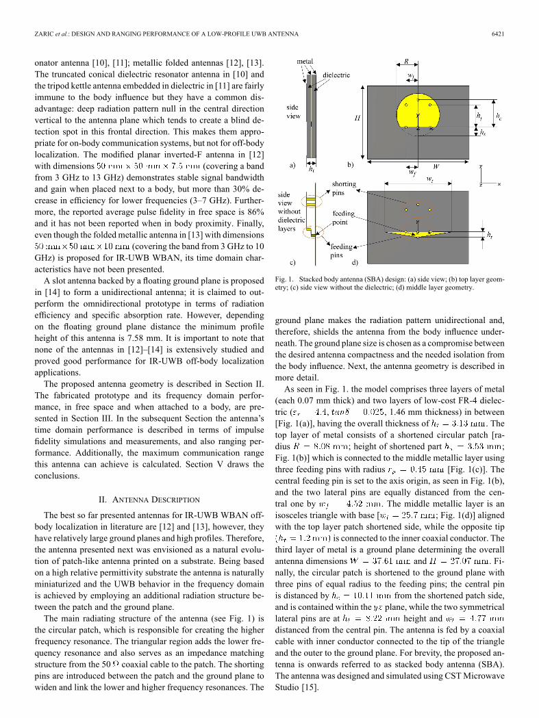
The best so far presented antennas for IR-UWB WBAN off-body localization in literature are [12] and [13], however, theyhave relatively large ground planes and high profiles. Therefore,the antenna presented next was envisioned as a natural evolu-tion of patch-like antenna printed on a substrate. Being basedon a high relative permittivity substrate the antenna is naturallyminiaturized and the UWB behavior in the frequency domainis achieved by employing an additional radiation structure be-tween the patch and the ground plane.The main radiating structure of the antenna (see Fig. 1) is
the circular patch, which is responsible for creating the higherfrequency resonance. The triangular region adds the lower fre-quency resonance and also serves as an impedance matchingstructure from the 50 coaxial cable to the patch. The shortingpins are introduced between the patch and the ground plane towiden and link the lower and higher frequency resonances. The
Fig. 1. Stacked body antenna (SBA) design: (a) side view; (b) top layer geom-etry; (c) side view without the dielectric; (d) middle layer geometry.
ground plane makes the radiation pattern unidirectional and,therefore, shields the antenna from the body influence under-neath. The ground plane size is chosen as a compromise betweenthe desired antenna compactness and the needed isolation fromthe body influence. Next, the antenna geometry is described inmore detail.As seen in Fig. 1. the model comprises three layers of metal
(each 0.07 mm thick) and two layers of low-cost FR-4 dielec-tric ( , , 1.46 mm thickness) in between[Fig. 1(a)], having the overall thickness of . Thetop layer of metal consists of a shortened circular patch [ra-dius ; height of shortened part ;Fig. 1(b)] which is connected to the middle metallic layer usingthree feeding pins with radius [Fig. 1(c)]. Thecentral feeding pin is set to the axis origin, as seen in Fig. 1(b),and the two lateral pins are equally distanced from the cen-tral one by . The middle metallic layer is anisosceles triangle with base [ ; Fig. 1(d)] alignedwith the top layer patch shortened side, while the opposite tip
is connected to the inner coaxial conductor. Thethird layer of metal is a ground plane determining the overallantenna dimensions and . Fi-nally, the circular patch is shortened to the ground plane withthree pins of equal radius to the feeding pins; the central pinis distanced by from the shortened patch side,and is contained within the plane, while the two symmetricallateral pins are at height anddistanced from the central pin. The antenna is fed by a coaxialcable with inner conductor connected to the tip of the triangleand the outer to the ground plane. For brevity, the proposed an-tenna is onwards referred to as stacked body antenna (SBA).The antenna was designed and simulated using CSTMicrowaveStudio [15].
6422 IEEE TRANSACTIONS ON ANTENNAS AND PROPAGATION, VOL. 62, NO. 12, DECEMBER 2014
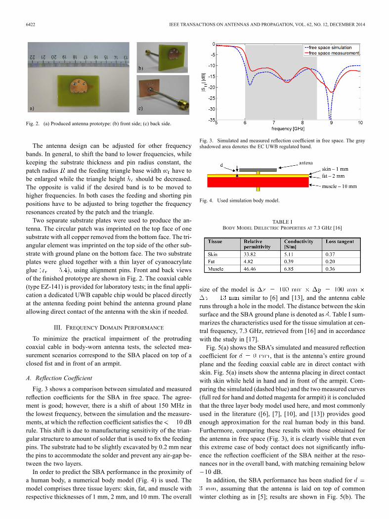
Fig. 2. (a) Produced antenna prototype: (b) front side; (c) back side.
The antenna design can be adjusted for other frequencybands. In general, to shift the band to lower frequencies, whilekeeping the substrate thickness and pin radius constant, thepatch radius and the feeding triangle base width have tobe enlarged while the triangle height should be decreased.The opposite is valid if the desired band is to be moved tohigher frequencies. In both cases the feeding and shorting pinpositions have to be adjusted to bring together the frequencyresonances created by the patch and the triangle.Two separate substrate plates were used to produce the an-
tenna. The circular patch was imprinted on the top face of onesubstrate with all copper removed from the bottom face. The tri-angular element was imprinted on the top side of the other sub-strate with ground plane on the bottom face. The two substrateplates were glued together with a thin layer of cyanoacrylateglue , using alignment pins. Front and back viewsof the finished prototype are shown in Fig. 2. The coaxial cable(type EZ-141) is provided for laboratory tests; in the final appli-cation a dedicated UWB capable chip would be placed directlyat the antenna feeding point behind the antenna ground planeallowing direct contact of the antenna with the skin if needed.
III. FREQUENCY DOMAIN PERFORMANCE
To minimize the practical impairment of the protrudingcoaxial cable in body-worn antenna tests, the selected mea-surement scenarios correspond to the SBA placed on top of aclosed fist and in front of an armpit.
A. Reflection Coefficient
Fig. 3 shows a comparison between simulated and measuredreflection coefficients for the SBA in free space. The agree-ment is good; however, there is a shift of about 150 MHz inthe lowest frequency, between the simulation and the measure-ments, at which the reflection coefficient satisfies the 10 dBrule. This shift is due to manufacturing sensitivity of the trian-gular structure to amount of solder that is used to fix the feedingpins. The substrate had to be slightly excavated by 0.2 mm nearthe pins to accommodate the solder and prevent any air-gap be-tween the two layers.In order to predict the SBA performance in the proximity of
a human body, a numerical body model (Fig. 4) is used. Themodel comprises three tissue layers: skin, fat, and muscle withrespective thicknesses of 1 mm, 2 mm, and 10 mm. The overall
Fig. 3. Simulated and measured reflection coefficient in free space. The grayshadowed area denotes the EC UWB regulated band.
Fig. 4. Used simulation body model.
TABLE IBODY MODEL DIELECTRIC PROPERTIES AT 7.3 GHZ [16]
size of the model issimilar to [6] and [13], and the antenna cable
runs through a hole in the model. The distance between the skinsurface and the SBA ground plane is denoted as . Table I sum-marizes the characteristics used for the tissue simulation at cen-tral frequency, 7.3 GHz, retrieved from [16] and in accordancewith the study in [17].Fig. 5(a) shows the SBA’s simulated and measured reflection
coefficient for , that is the antenna’s entire groundplane and the feeding coaxial cable are in direct contact withskin. Fig. 5(a) insets show the antenna placing in direct contactwith skin while held in hand and in front of the armpit. Com-paring the simulated (dashed blue) and the two measured curves(full red for hand and dotted magenta for armpit) it is concludedthat the three layer body model used here, and most commonlyused in the literature ([6], [7], [10], and [13]) provides goodenough approximation for the real human body in this band.Furthermore, comparing these results with those obtained forthe antenna in free space (Fig. 3), it is clearly visible that eventhis extreme case of body contact does not significantly influ-ence the reflection coefficient of the SBA neither at the reso-nances nor in the overall band, with matching remaining below10 dB.In addition, the SBA performance has been studied for
, assuming that the antenna is laid on top of commonwinter clothing as in [5]; results are shown in Fig. 5(b). The

ZARIC et al.: DESIGN AND RANGING PERFORMANCE OF A LOW-PROFILE UWB ANTENNA 6423
Fig. 5. (a) Simulated and measured reflection coefficient when the antenna isplaced in direct contact with skin. The inset figures show two types of bodymeasurement; (b) simulated and measured reflection coefficient when the an-tenna is placed 3 mm from the body. The inset figures show two types of bodymeasurement and the 3 mm foam separator, while the gray shadowed area inboth denotes the EC UWB regulated band.
same conclusion from the previous case can be drawn—theSBA is highly robust to body influence at any distance from thebody. Depending on the mounting area of the body, negligibledifferences in the reflection coefficient appear. Henceforward,body measurements will be made with the antenna placed infront of the armpit since this part of the body is more similar togeneral body area than the hand where fingers have higher bonetissue content.
B. Radiation Pattern and Transfer Function
Many UWB antennas tend to have a frequency dependent ra-diation pattern since in most cases each frequency may be ra-diated from different parts of the antenna [1]. This behavior iscommon to the proposed antenna as well. In Fig. 6, total elec-tric field radiation patterns are presented at three frequencies(6.1, 7.3, and 8.1 GHz) within the proposed antenna’s func-tional band and for the two main planes: and . Simula-tions correspond to free space (dashed red line) and body con-tact ( , dotted magenta line). Radiation pattern mea-surements were carried only in free space (full blue line), sincethe human body contact case was technically difficult to per-form in our facilities. As seen, the proposed antenna is nearlyunidirectional with average maximum gain around 5 dBi in freespace and around 6 dBi when placed next to a body. Comparingthe two simulated curves it is visible that the body influence onthe radiation pattern is small and concentrated in the hemi-sphere as expected, having in mind that the simulated radiation
pattern might not correspond completely to measurements on ahuman body because of the numerical model’s limited size andthickness. The SBA radiation is linearly polarized in plane inthe theta direction with cross polarized component level 20 dBbelow the dominant component for entire theta angle. In theplane polarization changes with angle: the two field componentshave equal magnitude at 30 and , except for the directionperpendicular to the antenna, while elsewhere the difference islarger than 10 dB.The SBA transfer function is also analyzed as a step for the
time domain characterization. In the experimental setup the an-tenna transfer function is obtained from the measuredbetween the SBA and a probe antenna using a vector networkanalyzer (VNA). A crossed exponential tapered slot antenna,XETS [18], is used as the probe, at 1 m distance from the SBA.The XETS antenna provides (within the [3.1, 10.1] GHz band)frequency stable radiation pattern, reasonably flat transfer func-tion with linear phase at least up to 8.5 GHz, and very pure linearpolarization [18]. Fig. 7 shows the measured for the SBAin free space (full blue curve), (red curve with circlemarker), and when in direct skin contact ( ; greencurve with triangle marker). It is notable that the antenna perfor-mance is very similar in each of the scenarios. When the SBA isin direct contact with skin or at 3 mm from the body, the transferfunction magnitude is slightly higher than in free spacewhich is consistent with previously observed radiation patterngain in free space and when next to a body. All three curves arereasonably flat over the entire desired band from 6 to 8.5 GHz,with linear phase without jumps, anticipating that all frequen-cies will be correctly radiated from the antenna and little distor-tion will be introduced to the pulse. This influence is quantifiedahead.
IV. TIME DOMAIN PERFORMANCE
Target localization using multilateration algorithms requiresaccurate simultaneous determination of its distance to differentfixed sensors. UWB ranging accuracy is strongly influenced bythe antenna time domain performance and this needs to be quan-tified. Used merit parameter is the impulse fidelity, as defined in[19], which gives a measure of the correlation between inputand transmitted pulse. Pulse fidelity and ranging accuracy re-sults are presented next for the SBA.The test impulse used in this paper is defined as [18]
(1)
where the central frequency is and Gaussianpulse width in order to comply with EC [3] andFCC [4] indoor UWB regulations. Its spectrum and time domainshape are shown in Fig. 8.
A. Antenna Pulse Fidelity
Pulse fidelity of the SBA is investigated for the half hemi-sphere in front of the antenna using CST solver. Linear po-

6424 IEEE TRANSACTIONS ON ANTENNAS AND PROPAGATION, VOL. 62, NO. 12, DECEMBER 2014
Fig. 6. Total electric field radiation pattern for: (a) plane 6.1 GHz; (b) plane 7.3 GHz; (c) plane 8.1 GHz; (d) plane 6.1 GHz; (e) plane 7.3 GHz;(f) plane 8.1 GHz. The inset figure denotes the and plane of the SBA.
Fig. 7. Measured transfer functions for the proposed antenna in free space andnext to a body ( and , armpit) in plane for : (a)amplitude; (b) phase. The gray shadowed area denotes the EC UWB regulatedband.
larization E-field far-field probes are distributed over thehemispherical surface. The probes are tangent to the surfaceand aligned with meridian lines starting in axis and endingin . The obtained transfer function between the SBA andeach probe is multiplied by the test impulse spectrum and trans-formed to time domain to obtain the received impulses usingstandard procedures [19].Fidelity is a correlation between the input and the output pulse
shape, as previously defined, when both pulses are scaled and
Fig. 8. Test pulse (a) spectrum and (b) time amplitude.
aligned. Fig. 9 shows input versus output pulse for three spe-cific directions for SBA in free space: (a) ; (b)
; (c) and in each sub-figure the fidelity of the output pulse is indicated. Clearly, thestronger is the resemblance between output and input pulses,the higher is the fidelity value. The fidelity is then calculated foreach direction in the whole front hemisphere for free space, for
and ; corresponding results are shown inFig. 10. Fidelity values range from 60% to 98%, with an averagevalue of 97%. The lowest fidelity values occur in the plane of

ZARIC et al.: DESIGN AND RANGING PERFORMANCE OF A LOW-PROFILE UWB ANTENNA 6425
Fig. 9. Scaled and aligned input and output pulses for three different SBA di-rections in free space depicting why fidelity is a good merit parameter for UWBantenna characterization: (a) ; (b) ; (c)
. In each subfigure the fidelity of the output pulse is indi-cated.
the antenna since the dominant radiation is in di-rection. The high average fidelity value is considerably higherthan for any other reported UWB WBAN antenna and antici-pates minimum output pulse distortion from the SBA, and con-sequently low ranging error as will be confirmed later.
B. Ranging Performance
SBA’s suitability for use in WBAN localization applicationsis demonstrated through real-life-like off-body ranging mea-surements. The proposed antenna is fixed on the body of a vol-unteer (female, 28 years old, 1.62 m and 54 kg) in front of thearmpit, with the coaxial cable passing under (see inset in Fig. 5);the XETS UWB sensor is located 1 m apart. Both antennas areconnected to a VNA (Agilent PNA E5071C) and after a full2-port calibration the respective scattering S-matrix is retrievedin the 5–10 GHz interval. The human subject is rotated aroundthe relevant SBA antenna axis in order to correctly retrieve datafor the antenna main planes. The correct distance between theantennas and the correct rotation angle are ensured by a fixedlaser guide above the volunteer and a grid design on the labora-tory floor. The -matrix is retrieved with 30 discretization fortheta angles from to in both the and -planefor off-body measurements, and with 10 discretization for freespace. The measurement points correspond in Fig. 10 to straighthorizontal and vertical lines passing in the center of the plots.The impulse response is obtained from the measured bypost processing as described in Section IV-A. Maximum peakdetection algorithm [20] is used to determine the time lag be-tween transmitted and received pulses and consequently the dis-tance between antennas.Fig. 11 presents fidelity and ranging data for the SBA main
planes in the three measured scenarios: free space, with bodycontact and 3 mm away from the skin. The inset sketch shows
the human subject and the measurement coordinate system rel-ative to the antenna. Fig. 11(a) for plane shows high fidelityvalues for the three scenarios from to while atand the fidelity is much lower for the free space scenario.These measurements correspond very well to simulated valuesin Fig. 10. The same correspondence between the measured andsimulated curves can be observed in Fig. 11(b) for plane.The ranging error for the two body scenarios is within 5 cm
which can be considered a very good accuracy, appropriate forUWB localization applications [2]. This kind of accuracy is veryimportant if it is necessary to know not only a person’s locationwithin premises, but also if they are standing, sitting, lying on abed, or lying on the floor.Another useful indicator of antenna performance in a local-
ization system is the maximum range it can achieve in a line-of-sight scenario. This number can be approximated using the fol-lowing expression:
(2)
where the is the 1 m measuring range, is theestimated maximum range, is the received power, is thestart frequency and is the end frequency of the used UWBband. is the pulse spectrum in Fig. 8(b) and is the mea-sured scattering coefficient. The calculatedmaximum ranges arepresented in Fig. 12 assuming the typical sensitivity of a UWBreceiver as . The maximum detectable rangeis between 3 m and 16 m for all three scenarios, which is suit-able for various indoor applications. It is stressed that for local-ization applications several fixed sensors are distributed in thescenario; for multilateration it is enough that three of them canget a good signal from the body antenna. The maximum esti-mated ranges for free space in Fig. 12 at are almostequal in both planes, while for the two body cases they are dif-ferent. This is due to the fact that the body is always in standingposition while the SBA is rotated accordingly to measure orplane; therefore, at 0 the conditions are not equal. The max-
imum estimated ranges in both planes are higher than 5 m foralmost all frontal directions allowing a reasonable distance be-tween the sensor and the target.The fact that the maximum range is similar in free space and
when in direct contact with skin shows indirectly that the SBAdoes not significantly loose efficiency when in body proximity.This is confirmed by simulations at three frequencies within theband as seen in Table II. At a single frequency (7.3 GHz) theefficiency in free space is 73% while it is 65% with skin contactand 67% at 3 mm distance from the body. It is stressed thatefficiency is penalized by the used FR-4 substrate which hashigh losses . If lower loss Rogers TMM4 wasused ( , ), the simulated efficiency forthe same antenna in free space at the central frequency would be95%. Table II shows that in the present case the lower value ofthe efficiency is a consequence of the lossy (low cost) substrateand it is not intrinsic to the SBA design.

6426 IEEE TRANSACTIONS ON ANTENNAS AND PROPAGATION, VOL. 62, NO. 12, DECEMBER 2014
Fig. 10. Pulse fidelity for hemisphere: (a) antenna in free space; (b) antenna at (body contact); (c) antenna at from the body. Theradial angle is and the azimuth angle is .
Fig. 11. Measured fidelities and ranging error for SBA-XETS distance of 1 m:(a) plane; (b) plane.
Fig. 12. Estimated maximum range for a SBA-XETS link: (a) plane; (b)plane.
TABLE IISIMULATED RADIATION EFFICIENCY
V. CONCLUSION
A novel low-profile UWB antenna appropriate for IRWBANlocalization applications was presented. It is unidirectional andpresents stable impedance and radiation pattern in the band, flatamplitude of the transfer function and linear phase to favor lowimpulse dispersion and high value of impulse fidelity in almostall radiation directions. Radiation efficiency is high both in freespace and in body proximity. All of the enumerated character-istics of SBA are highly immune to body influence and even todirect skin contact, which, to our best knowledge, has not beenreported yet in the literature. The antenna comprises three layersof metal and two layers of dielectric in between, which makesit less than a half of the height of other WBAN unidirectionalantennas.Reflection coefficient, and transfer coefficient, as well as ra-
diation pattern simulations and measurements demonstrate theproposed antenna capability to preserve good radiation charac-teristics even when placed in direct contact with human skin,and also when 3 mm from the body. Furthermore, the time do-main performance has been extensively studied and presented inform of upper hemisphere solid angle fidelity simulations andfidelity measurements with real human subjects. Achieved fi-delity values for most of the solid angle are higher than 95%, andoutperform so far published unidirectional antennas for WBANapplications.All measurements were performed in a laboratory environ-
ment in order to test the antenna in scenario as much as possiblesimilar to the desired final applications. Given the superior an-tenna performance in off-body WBAN ranging, with achieved
ZARIC et al.: DESIGN AND RANGING PERFORMANCE OF A LOW-PROFILE UWB ANTENNA 6427
accuracy of 5 cm, detection range larger than 5 m for most ofthe from hemisphere of the antenna and maximum range of 16m, it is very suitable for wide range of applications from civilto military, especially when a very precise location of a personis needed.
ACKNOWLEDGMENT
The authors acknowledge the collaboration from: C. Britofor prototype production, A. Almeida for prototype productionand measurements, and J. Silva and C. Cruz for prototype bodymeasurements.
REFERENCES[1] G. Adamiuk, T. Zwick, and W. Wiesbeck, “UWB antennas for com-
munication systems,” Proc. IEEE, vol. 100, pp. 1–14, Apr. 2012.[2] J. Rantakokko et al., “User requirements for localization and tracking
technology: A survey of mission-specific needs and constraints,” inProc. Int. Conf. Indoor Positioning and Indoor Navigation (IPIN), Sep.2010, pp. 1–9.
[3] Commission Decision on Allowing the use of the Radio Spectrumfor Equipment Using Ultra-Wideband Technology in a HarmonisedManner in the Community Official Journal of the European Union,2007/131/EC, 2007.
[4] Federal Communications Commission (FCC), First Order and Report:Revision of Part 15 of the Commission’s Rules Regarding UWBTrans-mission Systems FCC 02-48 2002.
[5] A. Alomainy, A. Sani, A. Rahman, J. G. Santas, and H. Yang, “Tran-sient characteristics of wearable antennas and radio propagation chan-nels for ultrawideband body-centric wireless communications,” IEEETrans. Antennas Propag., vol. 57, no. 4, pp. 875–884, Apr. 2009.
[6] D. Chun-Ping, L. Xiong-Ying, Z. Zhen-Kun, and M. M. Tentzeris,“A miniascape-like triple-band monopole antenna for WBAN applica-tions,” IEEE Antennas Wireless Propag. Lett., vol. 11, pp. 1330–1333,Nov. 2012.
[7] T. Tuovinen, M. Berg, K. Y. Yazdandoost, E. Salonen, and J. Iinatti,“Impedance behaviour of planar UWB antennas in the vicinity of adispersive tissue model,” in Proc. Loughborough Antennas and Prop-agation Conf. (LAPC), Nov. 2012, pp. 1–4.
[8] T. S. P. See and C. Zhi Ning, “Experimental characterization ofUWB antennas for on-body communications,” IEEE Trans. AntennasPropag., vol. 57, pp. 866–874, Apr. 2009.
[9] N. Chahat, M. Zhadobov, R. Sauleau, and K. Ito, “A compact UWBantenna for on-body applications,” IEEE Trans. Antennas Propag., vol.59, no. 1, pp. 1123–1131, Jan. 2011.
[10] G. Almpanis, C. Fumeaux, J. Frohlich, and R. Vahldieck, “A trun-cated conical dielectric resonator antenna for body-area network appli-cations,” IEEE Antennas Wireless Propag. Lett., vol. 8, pp. 279–282,May 2009.
[11] D. D. Cara, J. Trajkovikj, R. Torres-Sánchez, J. F. Zürcher, and A. K.Skrivervik, “A low profile UWB antenna for wearable applications:The tripod kettle antenna,” presented at the 7th Eur. Conf. Antennasand Propagation (EUCAP), Apr. 2013.
[12] S. Chan Hwang et al., “A low-profile ultra-wideband modified planarinverted-F antenna,” IEEE Trans. Antennas Propag., vol. 61, no. 1, pp.100–108, Jan. 2013.
[13] K. Cheng-Hung, W. Sung-Jung, and T. Jenn-Hwan, “A novel foldedUWB antenna for wireless body area network,” IEEE Trans. AntennasPropag., vol. 60, no. 2, pp. 1139–1142, Feb. 2012.
[14] M. Klemm, I. Z. Kovcs, G. F. Pedersen, and G. Troster, “Novel small-size directional antenna for UWB WBAN/WPAN applications,” IEEETrans. Antennas Propag., vol. 53, no. 12, pp. 3884–3896, Dec. 2005.
[15] 2013, CST—Computer Simulation Tech [Online]. Available: http://www.cst.com/
[16] 2013, Dielectric Properties of Body Tissues [Online]. Available: http://niremf.ifac.cnr.it/tissprop/
[17] S. Gabriel, R. W. Lau, and C. Gabriel, “The dielectric properties ofbiological tissues: III. Parametric models for the dielectric spectrum oftissues,” Phys. Med. Biol., vol. 41, pp. 2271–2293, Nov. 1996.
[18] J. R. Costa, C. R. Medeiros, and C. A. Fernandes, “Performance of acrossed exponentially tapered slot antenna for UWB systems,” IEEETrans. Antennas Propag., vol. 57, no. 5, pp. 1345–1352, May 2009.
[19] D. Lamensdorf and L. Susman, “Baseband-pulse-antenna techniques,”IEEE Antennas Propag. Mag., vol. 36, pp. 20–30, Feb. 1994.
[20] M. J. Kuhn, M. R. Mahfouz, C. Zhang, B. C. Merkl, and A. E. Fathy,“A system-level simulation framework for UWB localization,” IEEETrans. Microw. Theory Tech., vol. 58, no. 12, pp. 3527–3537, Dec.2010.
[21] PulsON-TimeDomain [Online]. Available: http://www.timedomain.com/p400.php
Andela Zaric (S’12) received the B.Sc. degree inelectrical engineering and information technologyand the M.Sc. degree in information and commu-nication technology from the Faculty of ElectricalEngineering and Computing, University of Zagreb,Zagreb, Croatia, in 2009 and 2011, respectively. Sheis currently working toward the Ph.D. degree fromthe Instituto Superior Técnico (IST), University ofLisbon, Lisbon, Portugal.Her research interests include UWB and RFID an-
tennas for detection and localization.Ms. Zaric received the first prize in the 2014 AP-S Student Design Contest
together with three team colleagues for designing and building a RFID-basedSmart Blood Stock System. In 2013, she received a travel and attendance grantfor European School of Antennas course “Antennas and Propagation for Body-Centric Wireless Communications.”
Jorge R. Costa (S’97–M’03–SM’09) was born inLisbon, Portugal, in 1974. He received the Licen-ciado and Ph.D. degrees in electrical and computerengineering from the Instituto Superior Técnico(IST), Technical University of Lisbon, in 1997 and2002, respectively.He is currently a Researcher at the Instituto de
Telecomunicações. He is also an Associate Professorwith the Departamento de Ciências e Tecnologiasda Informação, Instituto Universitário de Lisboa(ISCTE-IUL). His present research interests include
lenses, reconfigurable antennas, MEMS switches, UWB, MIMO, and RFIDantennas. He is the coauthor of four patent applications and more than 100 con-tributions to peer reviewed journals and international conference proceedings.More than 20 of these papers have appeared in IEEE Journals.Prof. Costa is currently serving as an Associate Editor for the IEEE
TRANSACTIONS ON ANTENNAS AND PROPAGATION and he was a Guest Editor ofthe Special Issue on “Antennas and Propagation at mm- and Sub mm-Waves”in the IEEE TRANSACTIONS ON ANTENNAS AND PROPAGATION, April 2013.
Carlos A. Fernandes (S’86–M’89–SM’08) re-ceived the Licenciado, M.Sc., and Ph.D. degrees inelectrical and computer engineering from InstitutoSuperior Técnico (IST), Technical University ofLisbon, Lisbon, Portugal, in 1980, 1985, and 1990,respectively.He joined IST in 1980, where he is presently
Full Professor at the Department of Electrical andComputer Engineering in the areas of microwaves,radio wave propagation, and antennas. He is a seniorresearcher at the Instituto de Telecomunicações and
member of the Board of Directors. He has been the leader of antenna activitiesin National and European Projects as RACE 2067–MBS (Mobile BroadbandSystem), ACTS AC230–SAMBA (System for Advanced Mobile BroadbandApplications), and ESA/ESTEC–ILASH (Integrated Lens Antenna Shaping).He has coauthored a book, a book chapter, and more than 130 technical papersin peer reviewed international journals and conference proceedings, in the areasof antennas and radiowave propagation modeling. His current research interestsinclude dielectric antennas for millimeter wave applications, antennas andpropagation modeling for personal communication systems, RFID antennas,artificial dielectrics and metamaterials. He was a Guest Editor of the SpecialIssue on “Antennas and Propagation at mm- and Sub mm-Waves” for the IEEETRANSACTIONS ON ANTENNAS AND PROPAGATION, April 2013.