
Design and implementation of LQG controller in Ball & Beam ...
19
Enviado: 17/08/2021 Recibido: 25/08/2021 Aceptado: 13/10/2021 VISIÓN ELECTRÓNICA Algo más que un estado sólido https://doi.org/10.14483/issn.2248-4728 Cite this article as: D. I. Zabala-Benavides, J. F. Salazar-Cáceres, “Design and implementation of LQG controller in Ball & Beam system”, Visión Electrónica, vol. 15, no. 2, 2021. https://doi.org/10.14483/22484728.17594 A RESEARCH VISION Design and implementation of LQG controller in Ball & Beam system Diseño e implementación de controlador LQG en sistema Ball & Beam Daniel Isaac Zabala-Benavides 1 , José Fabian Salazar-Cáceres 2 . Abstract The Ball & Beam system is one of the most complete case studies in control engineering, because it is a non-linear and naturally unstable system. In this article we propose to make an optimal LQG controller for Quanser's Ball & Beam system, composed of a linear quadratic regulator (LQR) and a linear quadratic estimator (Kalman filter) with which the noise of the system's ball position signal was eliminated, managing to mitigate the problems generated by the high sensitivity to sensor noise. Starting from the state space representation of the Quanser Ball & Beam system and using the Matlab/Simulink software and its QUARC module, an optimal LQG controller was designed, simulated and implemented in the Quanser Ball & Beam system. Finally, the simulation results and implementation show that the LQG controller is effective in controlling the Ball & Beam system despite the noise presented by the feedback signal. Keywords: Kalman filter, LQR, control, optimum, noise. 1 BSc. in Automation engineering, Universidad de La Salle, Colombia. Current position: Sophos Solutions, Colombia. Correo electrónico: [email protected] ORCID: https://orcid.org/0000-0002-7852-9946 2 BSc. in Electronic Design and Automation Engineering, Universidad de La Salle, Colombia. Correo electrónico: [email protected] ORCID: https://orcid.org/0000-0001-5949-3979
-
Upload
khangminh22 -
Category
Documents
-
view
0 -
download
0
Transcript of Design and implementation of LQG controller in Ball & Beam ...
Enviado: 17/08/2021 Recibido: 25/08/2021 Aceptado: 13/10/2021
VISIÓN ELECTRÓNICA
Algo más que un estado sólido
https://doi.org/10.14483/issn.2248-4728
Cite this article as: D. I. Zabala-Benavides, J. F. Salazar-Cáceres, “Design and implementation of LQG controller in Ball & Beam system”, Visión Electrónica, vol. 15, no. 2, 2021. https://doi.org/10.14483/22484728.17594
A RESEARCH VISION
Design and implementation of LQG controller in Ball & Beam system
Diseño e implementación de controlador LQG en sistema Ball & Beam
Daniel Isaac Zabala-Benavides1, José Fabian Salazar-Cáceres 2.
Abstract
The Ball & Beam system is one of the most complete case studies in control engineering,
because it is a non-linear and naturally unstable system. In this article we propose to make an
optimal LQG controller for Quanser's Ball & Beam system, composed of a linear quadratic
regulator (LQR) and a linear quadratic estimator (Kalman filter) with which the noise of the
system's ball position signal was eliminated, managing to mitigate the problems generated by
the high sensitivity to sensor noise. Starting from the state space representation of the Quanser
Ball & Beam system and using the Matlab/Simulink software and its QUARC module, an optimal
LQG controller was designed, simulated and implemented in the Quanser Ball & Beam system.
Finally, the simulation results and implementation show that the LQG controller is effective in
controlling the Ball & Beam system despite the noise presented by the feedback signal.
Keywords: Kalman filter, LQR, control, optimum, noise.
1 BSc. in Automation engineering, Universidad de La Salle, Colombia. Current position: Sophos Solutions, Colombia. Correo electrónico: [email protected] ORCID: https://orcid.org/0000-0002-7852-9946 2 BSc. in Electronic Design and Automation Engineering, Universidad de La Salle, Colombia. Correo electrónico: [email protected] ORCID: https://orcid.org/0000-0001-5949-3979
Resumen
El sistema Ball & Beam es uno de los casos de estudio más completos dentro la ingeniería de
control, debido a que es un sistema no lineal y naturalmente inestable. En el presente artículo
se propone realizar un controlador optimo LQG para el sistema Ball & Beam de Quanser,
compuesto por un regulador cuadrático lineal (LQR) y un estimador cuadrático lineal (filtro de
Kalman) por medio del cual se estimaron todos los estados del sistema, logrando mitigar las
problemáticas generadas por la alta sensibilidad al ruido del sensor. Partiendo de la
representación en espacio de estados del sistema Ball & Beam de Quanser y utilizando el
software Matlab/Simulink y su módulo QUARC se diseñó, simulo e implemento un controlador
optimo LQG en el sistema Ball & Beam de Quanser. Finalmente, los resultados de la simulación
e implementación muestran que el controlador LQG es efectivo para controlar el sistema Ball
& Beam a pesar del ruido que presenta la señal de realimentación.
Palabras clave: Filtro de Kalman, LQR, Control, Optimo, Ruido.
1. Introduction
In the process of controlling dynamic systems, it is common to find several complications due
to the instability of the systems, the presence of nonlinear components or the high sensitivity to
noise of the measuring instruments that integrate them. The Ball & Beam system is one of the
most complete case studies, since it presents all the mentioned complications, and whose
objective is to stabilize the position of a ball around an operating point, by means of the variation
of the inclination angle of a beam. Within the academy it is common to find several authors who
have developed and applied different control techniques for this system, some of the
documented cases will be described below.
With the objective of contemplating all the dynamics of the system, the nonlinearity presented
by the friction between the ball and the beam has been included in the mathematical modeling
of the Ball & Beam system [1]. The direct Lyapunov method has also been used to describe the
unstable behavior of the system [2]. Along with this, classical control loops were developed
such as PID controllers in series or in cascade [3] proportional feedback in state space and
Lag/Lead compensators, which, since they do not have any criteria for the control of the system,
have been developed. [2] which, not having optimal design criteria, generate inefficiency and
limit the operating conditions of the system.
These drawbacks generated those different authors raised various solutions from modern
control theories, such as optimal controllers which improved the efficiency of the system. The
optimal controller most named in the literature is the linear quadratic controller, which from
weight matrices established both heuristically and by optimization methods, minimizes the
energy required to control the system [4-5]. Parallel to this, quasi-optimal control techniques
were developed in time, which start from the transformation of the system to the Jordan model
[6]
On the other hand, it is common that the signals of the variables to be controlled present noise
components that directly affect the performance of the controller, for this reason the LQG
controller was developed alternatively [5] was developed, where a Kalman filter is used,
constructed from the state equations of the system or using the nonlinear differential system
written in Brunovsky's canonical form [4]. Through this filter the system states are estimated,
eliminating the noise of the associated signals and improving the system performance. In
addition to this, variants of this control technique were developed, such as the robust LQG/LTR
controller, which presents a better performance against disturbances or uncertainties that may
occur in systems such as Ball & Beam, or in rotary positioning systems [1] or in direct drive
rotary positioning systems [7].
The particular characteristics of the LQG controller have generated that it is used in external
control loops for the Ball & Plate system [8] system, and as a control strategy for much more
complex systems such as the Ballbot robot. [9]. Even this control technique has been integrated
with the feedforward controller for the development of control loops for NASA network antennas
[10].
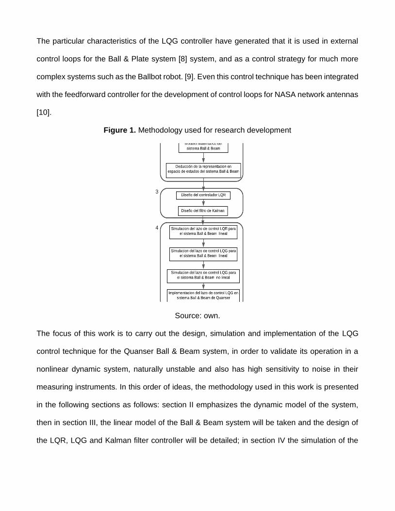
Figure 1. Methodology used for research development
Source: own.
The focus of this work is to carry out the design, simulation and implementation of the LQG
control technique for the Quanser Ball & Beam system, in order to validate its operation in a
nonlinear dynamic system, naturally unstable and also has high sensitivity to noise in their
measuring instruments. In this order of ideas, the methodology used in this work is presented
in the following sections as follows: section II emphasizes the dynamic model of the system,
then in section III, the linear model of the Ball & Beam system will be taken and the design of
the LQR, LQG and Kalman filter controller will be detailed; in section IV the simulation of the
different control loops will be developed, and the results obtained in the implementation of the
LQG control loop in the Ball & Beam system of Quanser will be shown. Figure (1) shows in
more detail the development of each of the above sections.
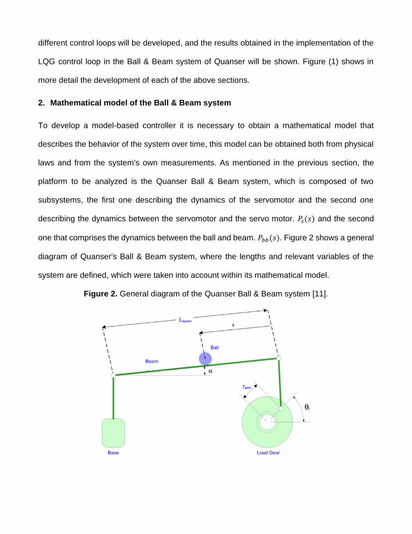
2. Mathematical model of the Ball & Beam system
To develop a model-based controller it is necessary to obtain a mathematical model that
describes the behavior of the system over time, this model can be obtained both from physical
laws and from the system's own measurements. As mentioned in the previous section, the
platform to be analyzed is the Quanser Ball & Beam system, which is composed of two
subsystems, the first one describing the dynamics of the servomotor and the second one
describing the dynamics between the servomotor and the servo motor. 𝑃𝑠(𝑠) and the second
one that comprises the dynamics between the ball and beam. 𝑃𝑏𝑏(𝑠). Figure 2 shows a general
diagram of Quanser's Ball & Beam system, where the lengths and relevant variables of the
system are defined, which were taken into account within its mathematical model.
Figure 2. General diagram of the Quanser Ball & Beam system [11].
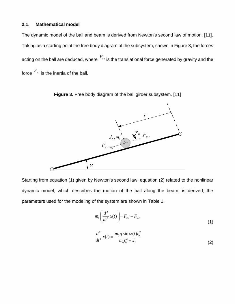
2.1. Mathematical model
The dynamic model of the ball and beam is derived from Newton's second law of motion. [11].
Taking as a starting point the free body diagram of the subsystem, shown in Figure 3, the forces
acting on the ball are deduced, where ,x tFis the translational force generated by gravity and the
force ,x rFis the inertia of the ball.
Figure 3. Free body diagram of the ball girder subsystem. [11]
Starting from equation (1) given by Newton's second law, equation (2) related to the nonlinear
dynamic model, which describes the motion of the ball along the beam, is derived; the
parameters used for the modeling of the system are shown in Table 1.
2
, ,2( )b x t x r
dm x t F F
dt
= −
(1)
22
2 2
sin ( )( ) b b
b b b
m g t rdx t
dt m r J
=
+ (2)
On the other hand, for the servomotor subsystem, the identification made in Quanser's
Workbook SRV2 was taken up again [11]. This transfer function is given in equation (3) and
describes the behavior of the servomotor with no load and with the highest gear configuration.
( ) 1.53( )
( ) (0.0248 1)
ls
m
sP s
V s s s
= =
+ (3)
Finally, by finding the relationship between the beam inclination angle and the angular
position of the gear l , equation (4) is obtained, which is linearized, defining that for angular
variations of l , close to 0°, it can be approximated that sin( )l l
.
22
2 2
sin ( )( )
( )
b l arm b
beam b b b
m g t r rdx t
dt L m r J
=
+ (4)
22
2 2
( )( )
( )
b l arm b
beam b b b
m g t r rdx t
dt L m r J
=
+ (5)
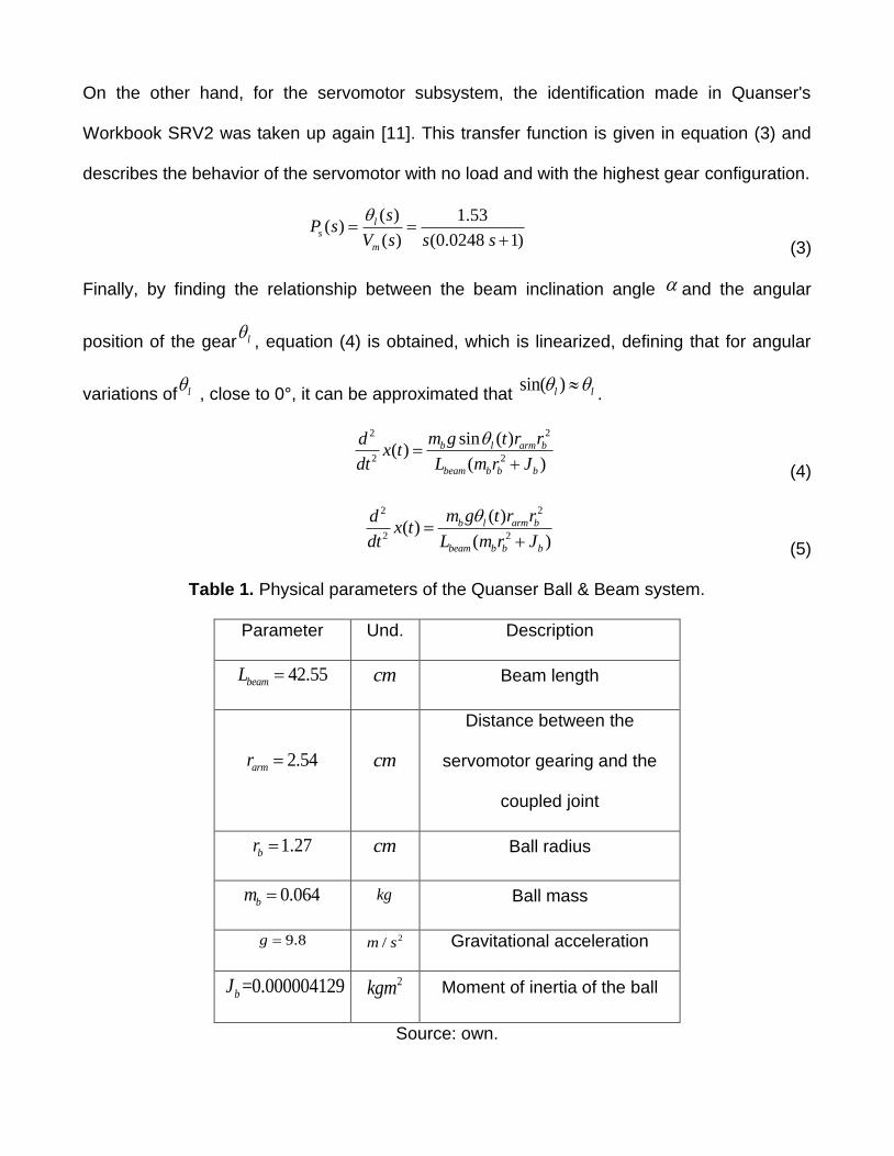
Table 1. Physical parameters of the Quanser Ball & Beam system.
Parameter Und. Description
42.55beamL = cm Beam length
2.54armr = cm
Distance between the
servomotor gearing and the
coupled joint
1.27br =
cm Ball radius
0.064bm =
kg Ball mass
9.8g = 2/m s Gravitational acceleration
=0.000004129bJ
2kgm Moment of inertia of the ball
Source: own.
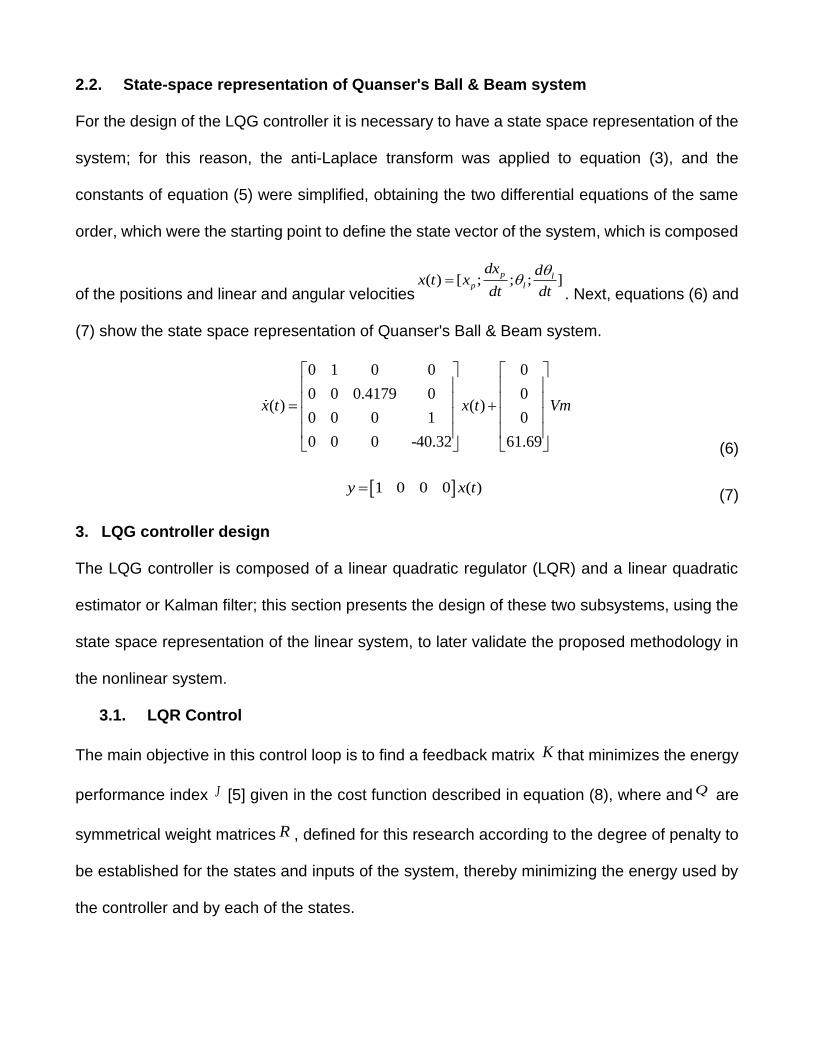
2.2. State-space representation of Quanser's Ball & Beam system
For the design of the LQG controller it is necessary to have a state space representation of the
system; for this reason, the anti-Laplace transform was applied to equation (3), and the
constants of equation (5) were simplified, obtaining the two differential equations of the same
order, which were the starting point to define the state vector of the system, which is composed
of the positions and linear and angular velocities( ) [ ; ; ; ]
p lp l
dx dx t x
dt dt
=
. Next, equations (6) and
(7) show the state space representation of Quanser's Ball & Beam system.
0 1 0 0 0
0 0 0.4179 0 0( ) ( )
0 0 0 1 0
0 0 0 -40.32 61.69
x t x t Vm
= + (6)
1 0 0 0 ( )y x t= (7)
3. LQG controller design
The LQG controller is composed of a linear quadratic regulator (LQR) and a linear quadratic
estimator or Kalman filter; this section presents the design of these two subsystems, using the
state space representation of the linear system, to later validate the proposed methodology in
the nonlinear system.
3.1. LQR Control
The main objective in this control loop is to find a feedback matrix K that minimizes the energy
performance index J [5] given in the cost function described in equation (8), where and Q are
symmetrical weight matrices R , defined for this research according to the degree of penalty to
be established for the states and inputs of the system, thereby minimizing the energy used by
the controller and by each of the states.

0
( )T TJ x Qx u Ru dt
= + (8)
To obtain the matrix K , an analysis of the problem is made from the Euler-Lagrange equations
and application of the Variational Calculus, resulting in the control law in the form of state
feedback given in equation (9).
1 TK R B P−= − (9)
Where P is the algebraic solution of the Riccati equation, described in equation (10).
1 0T TA P PA PBR B P Q−+ − + = (10)
Finally, an optimal state feedback was performed according to the control law u Kx= − , where
is K the optimal gain matrix found previously.
3.2. Kalman Filter
The Kalman filter is widely used in fields such as digital image processing, computer vision,
pattern recognition and state estimation for stochastic systems.
The Ball & Beam system has a variable resistance sensor that allows measuring the position
of the ball along the beam, however, the measurement of this state is affected by the high
sensitivity to noise that the measuring instrument presents, causing the measurement of the
state to pxbecome a stochastic process. Therefore, it was necessary to define a state space
representation of the system, where the components ( )w t associated to the process noise and
( )v t associated to the noise present in the measurement of the output variable were added to
the dynamics of this state, as shown in equations 10 and 11.
( ) ( ) ( ) ( )x t Ax t Bu t w t= + + (10)
( ) ( ) ( )y t Cx t v t= + (11)
Then, since the analysis, design and implementation of the Kalman filter is simplified by using
the dynamic equations of the system in the discrete domain, it was decided to use a zero-order
retainer to discretize the system given by equations (10) and (11); obtaining as a result the
system described in equations (12) and (13), where the matrices dA , and dB
are wd related to
the equation of states of the system in the discrete domain, and the matrices dC andvd are
related to the output equation of the system in the discrete domain.
( 1) ( ) ( ) ( )k d k d k kx A x B u wd+ = + + (12)
( ) ( ) ( )k d k ky C x vd= + (13)
Based on the above, the Kalman filter was designed, which is an algorithm derived from the
optimal state estimation, where it is stated that the random components and ( )kwd ( )kvdhave a
Gaussian distribution with zero mean and non-zero covariance. Therefore, for this research the
matrices EQ associated to the process noise covariance and MR
associated to the measurement
noise covariance were defined.
( ) (0, )k Mvd N R (12)
( ) (0, )k Ewd N Q (13)
Then, as a first step, the prediction and covariance equations were established, which are
stated in equations 14 and 15 respectively.
( 1) ( 1)ˆ ˆ
k d k d kx A x B u−
− −= + (14)
( 1)
T
k d k d EP A P A Q−
−= + (15)
Secondly, the update equations for both the prediction and the error covariance, described in
equations 17 and 18, were declared.
1
( ) ( ) ( )( )T T
k k d d k d Mk P C C P C R− − −= + (16)
( 1) ( ) ( ) ( ) ( )ˆ ˆ ˆ( )k k k k d tx x k y C x− −
− = + − (17)
( ) ( ) ( )(1 )k k d kP k C P−= − (18)
The term ( )kk, described in equation (16), is the optimal gain matrix of the Kalman filter, which
minimizes the covariance of the updated error ( )kP .
Finally, integrating the Kalman filter within the LQR control loop, the LQG control technique is
designed, where the cost function for the Ball & Beam system, given by equations (12) and
(13), is minimized. Figure 4 shows the interconnection between the Ball & Beam system, the
Kalman filter and the set of optimal gains within K the LQG control loop in the discrete domain.
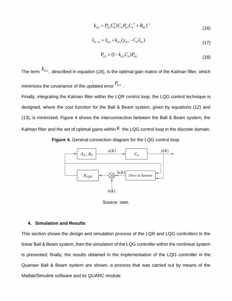
Figure 4. General connection diagram for the LQG control loop.
Source: own.
4. Simulation and Results
This section shows the design and simulation process of the LQR and LQG controllers in the
linear Ball & Beam system, then the simulation of the LQG controller within the nonlinear system
is presented; finally, the results obtained in the implementation of the LQG controller in the
Quanser Ball & Beam system are shown, a process that was carried out by means of the
Matlab/Simulink software and its QUARC module.
Before starting the design process of the LQG and LQR controllers, it was validated that the
linear system was both observable and controllable, corroborating that the range of the
controllability and observability matrices was equal to the degree of the system. After that, the
design of the LQR controller was carried out, where the weight matrices Q and R were
configured, as shown below.
100 0 0 0
0 10 0 0
0 0 100 0
0 0 0 10
Q
= ;
10R =
By solving the algebraic Riccati equation, the optimal K feedback gain matrix, described below,
was obtained.
3.1623 8.1243 4.2963 0.5980K =
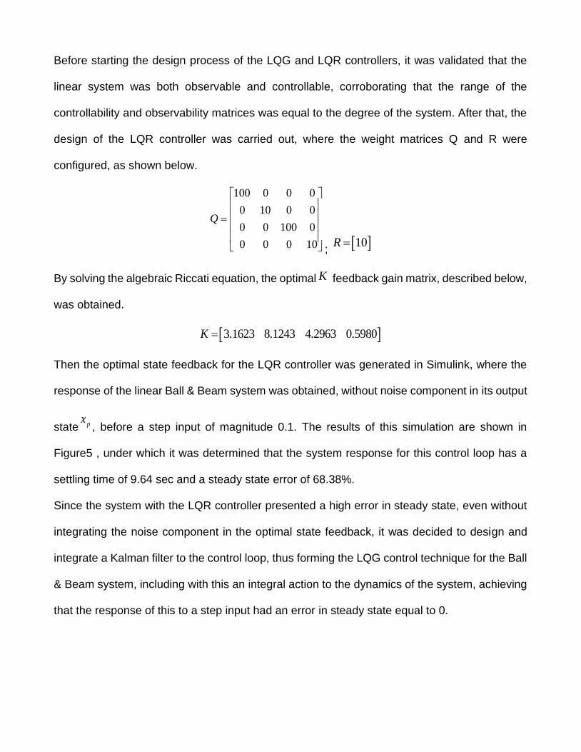
Then the optimal state feedback for the LQR controller was generated in Simulink, where the
response of the linear Ball & Beam system was obtained, without noise component in its output
state px, before a step input of magnitude 0.1. The results of this simulation are shown in
Figure5 , under which it was determined that the system response for this control loop has a
settling time of 9.64 sec and a steady state error of 68.38%.
Since the system with the LQR controller presented a high error in steady state, even without
integrating the noise component in the optimal state feedback, it was decided to design and
integrate a Kalman filter to the control loop, thus forming the LQG control technique for the Ball
& Beam system, including with this an integral action to the dynamics of the system, achieving
that the response of this to a step input had an error in steady state equal to 0.
Figure 5. LQR control loop, ball position control.
Source: own.
For the design of the Kalman filter, the covariance matrices and EQ MR , associated with the
covariance of the process noise and the covariance of the noise of the system output equation,
respectively, were declared.
0.1 0 0 0
0 0.1 0 0
0 0 0.1 0
0 0 0 0.1
EQ
= ;
0.01MR =
Using the Kalman filter algorithm, the matrix k , which corresponds to the set of optimal gains
of the linear quadratic estimator, was calculated.
1.1756 0.6410 0.3163 0.0000T
k =
For the development of the simulation of the LQG control loop in the linear Ball & Beam system,
a random signal of Gaussian distribution with mean 0 and covariance of 0.01 was added in the
state feedback px, in order to replicate the high sensitivity to noise presented by the linear
position sensor of the system. The figure 6shows the response of the LQG control loop in the
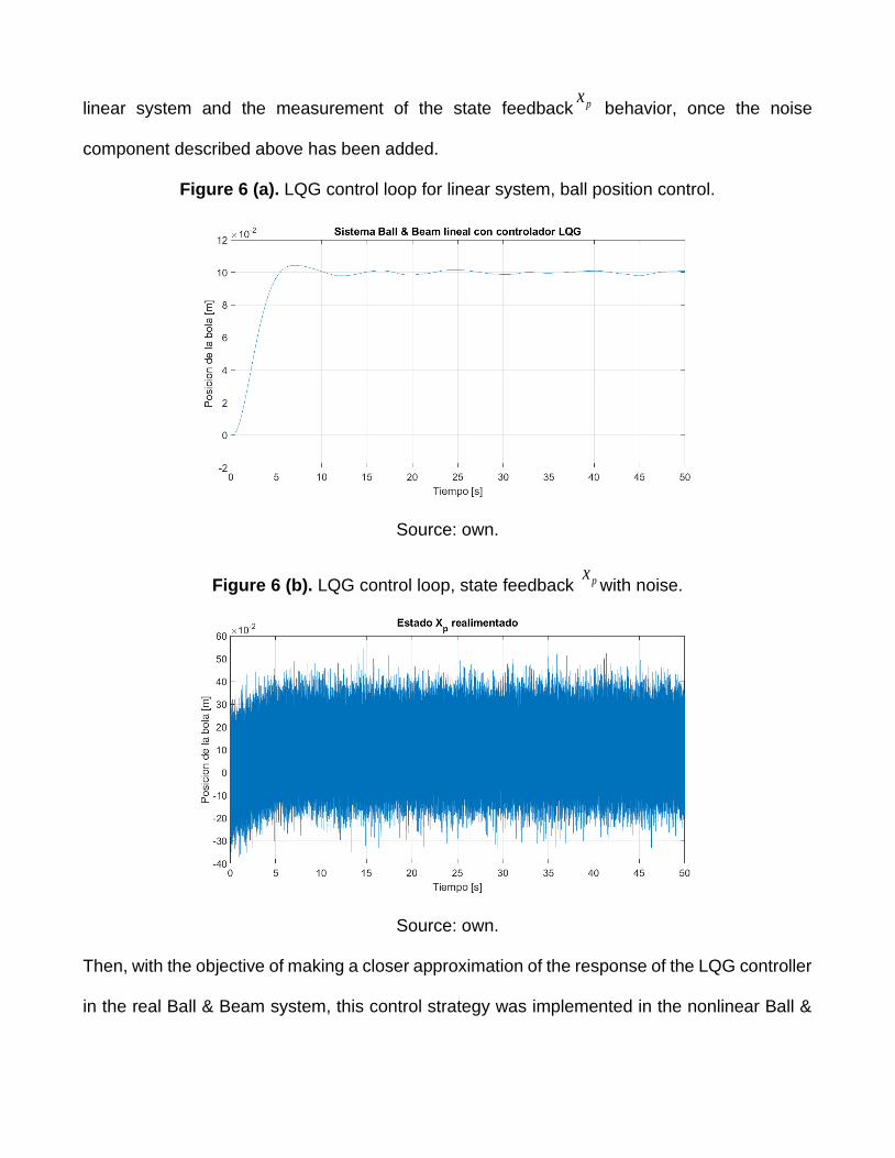
linear system and the measurement of the state feedback px behavior, once the noise
component described above has been added.
Figure 6 (a). LQG control loop for linear system, ball position control.
Source: own.
Figure 6 (b). LQG control loop, state feedback pxwith noise.
Source: own.
Then, with the objective of making a closer approximation of the response of the LQG controller
in the real Ball & Beam system, this control strategy was implemented in the nonlinear Ball &
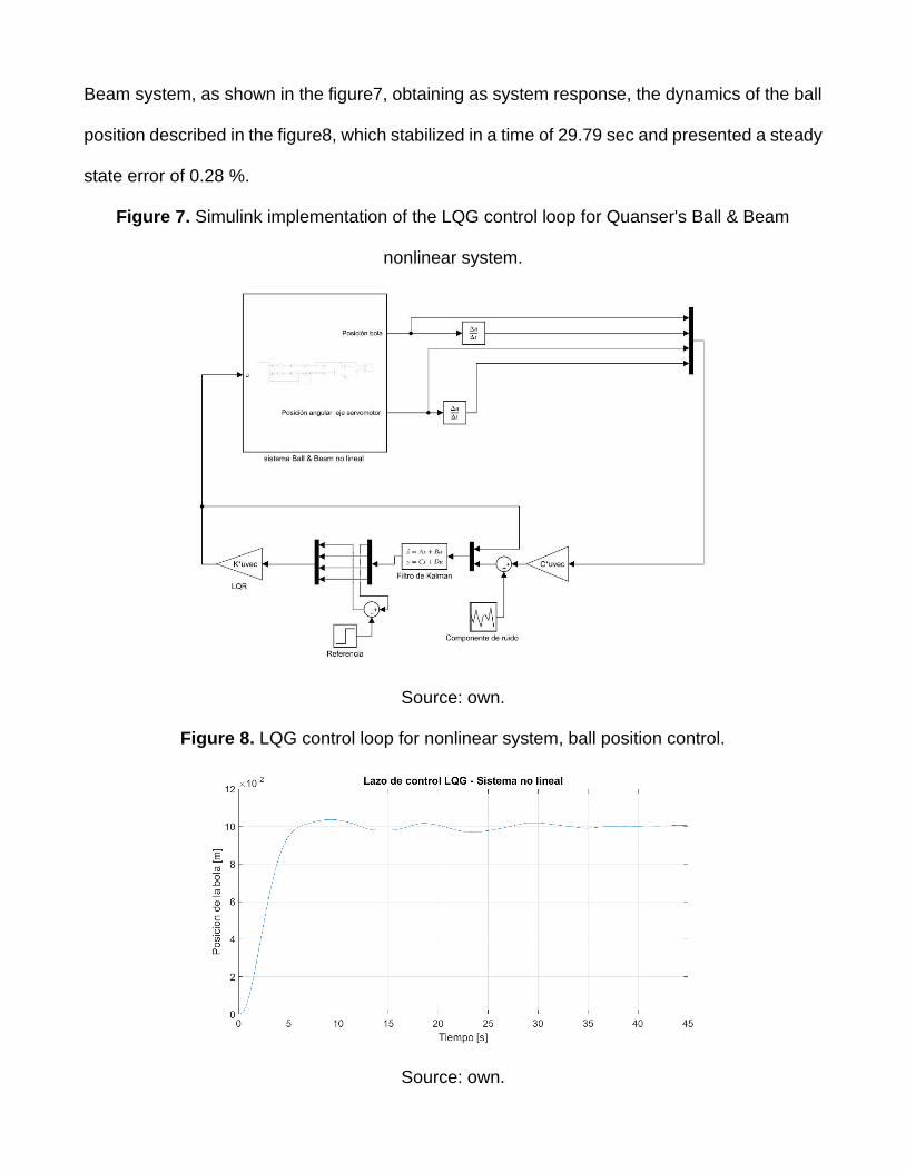
Beam system, as shown in the figure7, obtaining as system response, the dynamics of the ball
position described in the figure8, which stabilized in a time of 29.79 sec and presented a steady
state error of 0.28 %.
Figure 7. Simulink implementation of the LQG control loop for Quanser's Ball & Beam
nonlinear system.
Source: own.
Figure 8. LQG control loop for nonlinear system, ball position control.
Source: own.
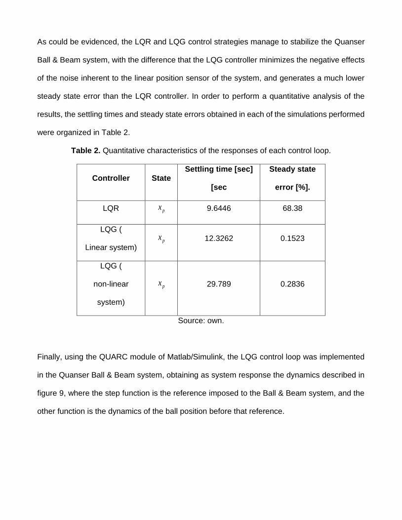
As could be evidenced, the LQR and LQG control strategies manage to stabilize the Quanser
Ball & Beam system, with the difference that the LQG controller minimizes the negative effects
of the noise inherent to the linear position sensor of the system, and generates a much lower
steady state error than the LQR controller. In order to perform a quantitative analysis of the
results, the settling times and steady state errors obtained in each of the simulations performed
were organized in Table 2.
Table 2. Quantitative characteristics of the responses of each control loop.
Controller State Settling time [sec]
[sec
Steady state
error [%].
LQR px
9.6446 68.38
LQG (
Linear system) px
12.3262 0.1523
LQG (
non-linear
system)
px
29.789 0.2836
Source: own.
Finally, using the QUARC module of Matlab/Simulink, the LQG control loop was implemented
in the Quanser Ball & Beam system, obtaining as system response the dynamics described in
figure 9, where the step function is the reference imposed to the Ball & Beam system, and the
other function is the dynamics of the ball position before that reference.
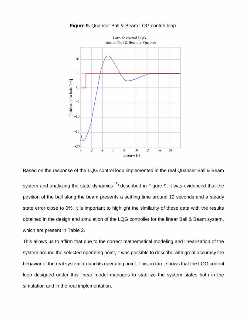
Figure 9. Quanser Ball & Beam LQG control loop.
Based on the response of the LQG control loop implemented in the real Quanser Ball & Beam
system and analyzing the state dynamics pxdescribed in Figure 9, it was evidenced that the
position of the ball along the beam presents a settling time around 12 seconds and a steady
state error close to 0%; it is important to highlight the similarity of these data with the results
obtained in the design and simulation of the LQG controller for the linear Ball & Beam system,
which are present in Table 2.
This allows us to affirm that due to the correct mathematical modeling and linearization of the
system around the selected operating point, it was possible to describe with great accuracy the
behavior of the real system around its operating point. This, in turn, shows that the LQG control
loop designed under this linear model manages to stabilize the system states both in the
simulation and in the real implementation.
5. Conclusions
An LQG controller was designed, simulated and implemented for the Quanser Ball & Beam
system, achieving to stabilize the position of the ball along the beam. Additionally, by means of
a comparative analysis between the LQR and LQG controllers, it was validated that only the
LQR controller is not efficient to control the Ball & Beam system, because the response of this
control loop presents a high steady state error, even without the presence of noise in the state
feedback px, which is associated to the measurement of the linear position of the ball. On the
other hand, it was validated that the LQG controller is efficient to control the Ball & Beam
system, since it manages to stabilize the system states with a steady state error close to 0%,
both in the presence and in the absence of noise in the measurement of its output state; This
is due to the fact that during the design of the LQG controller, both the noise associated with
the process and the noise associated with the measurement of the output state are taken into
consideration, thus generating an optimal estimation of all the states of the system, allowing to
improve both the performance of the controller and the response of the system. For this reason,
it can be stated that the LQG control technique is effective to control the Ball & Beam system,
even when there is noise in the measurement of its output state.
References
[1] D. Colón, Y. S. Andrade, Á. M. Bueno and S. D. Ivando , "MODELING, CONTROL AND
IMPLEMENTATION OF A BALL AND BEAM," ResearchGate, 2014.
[2] S. Valluru, M. Singh, and S. Singh, "Prototype Design and Analysis of Controllers for One
Dimensional Ball and Beam System," IEEE International Conference on Power
Electronics., 2016.
[3] D. L. Mariño Lizarazo, J. A. Tumialan Borja, “Ball & beam control system using
matlab and lego nxt”, Visión Electrónica, vol. 8, no. 2, pp. 39–48, 2014.
https://doi.org/10.14483/22484728.9871
[4] S. Mustansar, A. Rahat, M. M. Fahad, "Control of Ball and Beam with LQR Control
Scheme using Flatness Based Approach", College of Elecrical and Mechanical
Engineering.
[5] S. Rahul, D. Sathans, "Optimal Control of a Ball and Beam System through LQR and
LQG," IEEE, 2018.
[6] C. N. Xuan, H. P. Nguyen, L. H. Duc, K. T. Dang, M. K. Le, and T. X. Pham, "BUILDING
QUASI-TIME-OPTIMAL CONTROL LAWS FOR BALL AND BEAM SYSTEM," IEEE,
2019.
[7] X. Wang, "Using LQG-LTR control law to improve the performance of direct drive rotary
positioning system subject to uncertain inertia load," IEEE, 2011.
https://doi.org/10.1109/FPM.2011.6045898
[8] A. Umar, U. Aliyu, M. Umar, M. Y. Abdulmumin, "Linear Quadratic Gaussian (LQG)
Control Design for Position and Trajectory Tracking of the Ball and Plate System," IEEE,
2017.
[9] D. V. Thach, S. G. Lee, "LQG Control Design for a Coupled Ballbot Dynamical System,"
International Conference on Control, Automation and Systems, 2018.
[10] K. G. Wodeck, C. S. Racho, A. M. Jeffrey, "Application of the LQG and Feedforward
Controllers to the Deep Space Network Antennas", IEEE, 1995.
[11] Quanser Inc, "QUANSER INNOVATE EDUCATE", 2011. [Online]. Available:
https://www.quanser.com/products/ball-and-beam/