Design and Implementation of a Wireless Fluid Level Display ...
11
_____________________________________________________________________________________________________ *Corresponding author: Email: [email protected]; Journal of Engineering Research and Reports 14(1): 30-40, 2020; Article no.JERR.58077 ISSN: 2582-2926 Design and Implementation of a Wireless Fluid Level Display System Using Ultrasonic Sensing Technique Gesa F. Newton 1* , Terwase I. Aondona 1 and C. A. Chile 2 1 Department of Physics, University of Agriculture Makurdi, P.M.B. 2373, Benue State, Nigeria. 2 Department of Physics, Benue State University, P.M.B. 102119 Makurdi, Benue State, Nigeria. Authors’ contributions This work was carried out in collaboration among all authors. Author GFN designed the research, the algorithm, developed the program codes in C, Author TIA made the schematics using Proteus software, simulated the designs and wrote the first draft of the manuscript. Author CAC did soldering, system testing and evaluation as well as proof-reading of the drafted manuscript. All authors read and approved the final manuscript. Article Information DOI: 10.9734/JERR/2020/v14i117116 Editor(s): (1) Dr. Ravi Kant, Maharaja Ranjit Singh Punjab Technical University, India. Reviewers: (1) Shashikant Sadistap, Central Electronics Engineering Research Institute, India. (2) Anak Agung Ngurah Gunawan, Universitas Udayana, Indonesia. Complete Peer review History: http://www.sdiarticle4.com/reviewhistory/58077 Received 14 April 2020 Accepted 20 June 2020 Published 30 June 2020 ABSTRACT The wireless fluid level indicator comprises a sensing and transmitting circuit for detecting and transmitting the levels of fluids from a container to the receiving circuit which receives and displays the amount of the measured volume. This has been achieved using an ultrasonic sensor (HC SR04), a firmware (PIC16F648A/PIC16F876A microcontroller programmed in C/assembly languages), an encoder (HT12E) and a radio frequency (RF) transmitter transmitting at a bandwidth of 433MHz to an RF receiver interfaced with a decoder (HT12D), liquid crystal display (LCD) and a Buzzer. The device when tested measured water levels and transmitted same over a distance of up to 98.5 meters in open areas and up to 50 meters in highly obstructed areas. The average response time was also estimated to be 0.1 second. As a contactless depth detection system, the device finds useful applications in measurement of fluid levels in homes and industries where concentrates, table water, transmission oils are produced, without affecting the chemical or physical properties of such substancesan advantage over the contact methods used in fluid level detection. Aims: To design and implement a wireless microcontroller based fluid level display system using ultrasonic sensing method. Original Research Article
-
Upload
khangminh22 -
Category
Documents
-
view
2 -
download
0
Transcript of Design and Implementation of a Wireless Fluid Level Display ...

_____________________________________________________________________________________________________ *Corresponding author: Email: [email protected];
Journal of Engineering Research and Reports
14(1): 30-40, 2020; Article no.JERR.58077 ISSN: 2582-2926
Design and Implementation of a Wireless Fluid Level Display System Using Ultrasonic Sensing Technique
Gesa F. Newton1*, Terwase I. Aondona1 and C. A. Chile2
1Department of Physics, University of Agriculture Makurdi, P.M.B. 2373, Benue State, Nigeria.
2Department of Physics, Benue State University, P.M.B. 102119 Makurdi, Benue State, Nigeria.
Authors’ contributions
This work was carried out in collaboration among all authors. Author GFN designed the research, the algorithm, developed the program codes in C, Author TIA made the schematics using Proteus
software, simulated the designs and wrote the first draft of the manuscript. Author CAC did soldering, system testing and evaluation as well as proof-reading of the drafted manuscript. All authors read and
approved the final manuscript.
Article Information
DOI: 10.9734/JERR/2020/v14i117116 Editor(s):
(1) Dr. Ravi Kant, Maharaja Ranjit Singh Punjab Technical University, India. Reviewers:
(1) Shashikant Sadistap, Central Electronics Engineering Research Institute, India. (2) Anak Agung Ngurah Gunawan, Universitas Udayana, Indonesia.
Complete Peer review History: http://www.sdiarticle4.com/reviewhistory/58077
Received 14 April 2020 Accepted 20 June 2020
Published 30 June 2020
ABSTRACT
The wireless fluid level indicator comprises a sensing and transmitting circuit for detecting and transmitting the levels of fluids from a container to the receiving circuit which receives and displays the amount of the measured volume. This has been achieved using an ultrasonic sensor (HCSR04), a firmware (PIC16F648A/PIC16F876A microcontroller programmed in C/assembly languages), an encoder (HT12E) and a radio frequency (RF) transmitter transmitting at a bandwidth of 433MHz to an RF receiver interfaced with a decoder (HT12D), liquid crystal display (LCD) and a Buzzer. The device when tested measured water levels and transmitted same over a distance of up to 98.5 meters in open areas and up to 50 meters in highly obstructed areas. The average response time was also estimated to be 0.1 second. As a contactless depth detection system, the device finds useful applications in measurement of fluid levels in homes and industries where concentrates, table water, transmission oils are produced, without affecting the chemical or physical properties of such substancesan advantage over the contact methods used in fluid level detection. Aims: To design and implement a wireless microcontroller based fluid level display system using ultrasonic sensing method.
Original Research Article

Gesa et al.; JERR, 14(1): 30-40, 2020; Article no.JERR.58077
31
Study Design: By encoding the Transmitter module to sense and detect the amount of water level, while the decoder module decodes the received data and display the result. Place and Duration of Study: Department of Physics, University of Agriculture Makurdi, Benue State, Nigeria, between November 2018 and April 2019. Methodology: An RF transceiver, encoder/decoder (HT12E/HT12D), a 2x16 Liquid display module, 4MHz crystal oscillator, a buzzer and other peripherals were interfaced to two 8bit controllers; PIC16F648A and PIC16F876A. The controllers were programmed in C/Assembly languages to enable effective communication of the system. The system was then calibrated to read and transmit water level values from a 30centimeter deep tank over a distance of 1.0 98.5 meters. Results: The system was tested to have maximum sensitivity over a distance of 98.5 meters in nonobstructed areas and 50 meters in obstructed areas. The average response time was also estimated to be 0.5 seconds. Conclusion: The design and implementation of a wireless fluid level display system using ultrasonic sensing technique has been successfully done. The system workability is suitable for deployment and usage in domestic and industrial purposes.
Keywords: Wireless; fluid level; ultrasonic-sensor; microcontroller.
1. INTRODUCTION In most places and systems where fluids are stored and used, fluid management systems are designed in a way that the level of fluid may be easily seen with the naked eyes for those in open surfaces and transparent containers. However, in opaque containers and closed systems such as overhead tanks, visualizing the fluid level becomes a difficult task and requires technological application. To monitor the fluid level/content in most such fluid systems, called fluid level indicators like float level indicators or mechanical float gauges could be used. The origin of these devices can be traced back from the discovery of electron by J.J Thompson down to solid state devices where transistors and microprocessors used in the design of electronic devices arose [1,2].
Nowadays, with more technological innovations, proper monitoring and management of fluid could be achieved using electronic devices such as, temposonic sensors, fluid alarms and ultrasonic level detectors. Some of these fluid level indicators are contact based and hence have their own limitations and side effects. These shortcomings include corrosion of metal parts leading to less reading accuracy of the instruments, as well as contamination of such fluids. Also, the proximity of these devices to the containing vessels introduces the burden of continuous check by the user visavis fluid levels. This can be a stressful exercise. Also, contact based indicators has become a lagging technology which requires an upgrade. The numerous setbacks created and encountered in
these contact based fluid level indicators and other ineffective and inefficient fluid level indicators have generated a problem which needs to be addressed.
This research focuses on the design and implementation of a wireless microcontroller based fluid level sensing and display system which entails the assembling of components such as ultrasonic sensors, transistors, radio frequency transmitters and receivers with a microcontroller interfaced to determine, process and display accurately the level of fluid in a container. This would enhance fluid level monitoring which in turn minimizes wastage of fluids (e.g. water) during pumping process. Additionally, the accurate determination of fluid level in the septic tanks would eliminate emergency runout of water in homes or industries. Hence, this research emphasizes the application and utilization of electrical and electronic theories, methods and techniques for effective determination of fluid levels by considering a wireless transmission mode communication between the interfaced component units.
1.1 Review of Related Works
Reza et al. [3] designed a microcontrollerbased automatic water level sensing and controlling device to monitor and manage water utilization [3]. The system was implemented based on the contactmethod of fluid detection. The variation of water conductivity with change of depth was deployed in which an LED indicated the different water levels. The device offered a good water control measure.
Gesa et al.; JERR, 14(1): 30-40, 2020; Article no.JERR.58077
32
Another work presented by Ayob et al. [4] uses the contact method of fluid sensing via sensing probes interface to a microcontroller (PIC16F877A) circuitry. To keep tracked of the measure and processed water level, the global system of mobile (GSM) communication network was deployed to send short messages (alerts) to the user [4]. To achieve the level transmission, a GSM module was interfaced to MAX232 thereby providing a hyperterminal protocol that checks the microcontroller operation. In another related research, Ejiofor and Oladipo [5] presented a microcontroller based automatic water level control system where the work of detecting the level of water was done by LM324 comparator. An AT86C52 microcontroller was used to control the functionality of the entire system [5]. As a contact method, the circuit relied on copper conductors to transfer voltage to the comparator circuit and the microcontroller. The status is then displayed on an LCD screen while utilizing relays in the switching circuit to trigger ON or OFF the pump depending on the water level. More so, by using contact method; Naregalkar et al. [6] designed a wireless water level indicator. In the work, a PIC 16F877A microcontroller was interfaced with sensing probes and then programmed to monitor the water level of an overhead tank placed up to 100 meters away. Using a radio frequency system the measured and processed water levels were put across to the user [6]. However, the sensing probes placed in the water have a tendency of affecting the purity of the water through corrosion leading to rusting in the long run.
1.2 Sensors A sensor is a device that takes in the input signal by detecting events or changes in its environment and then producing a corresponding output. Though different types of sensors have their own mode of operation but generally a sensor acts as a transducer by acquiring a
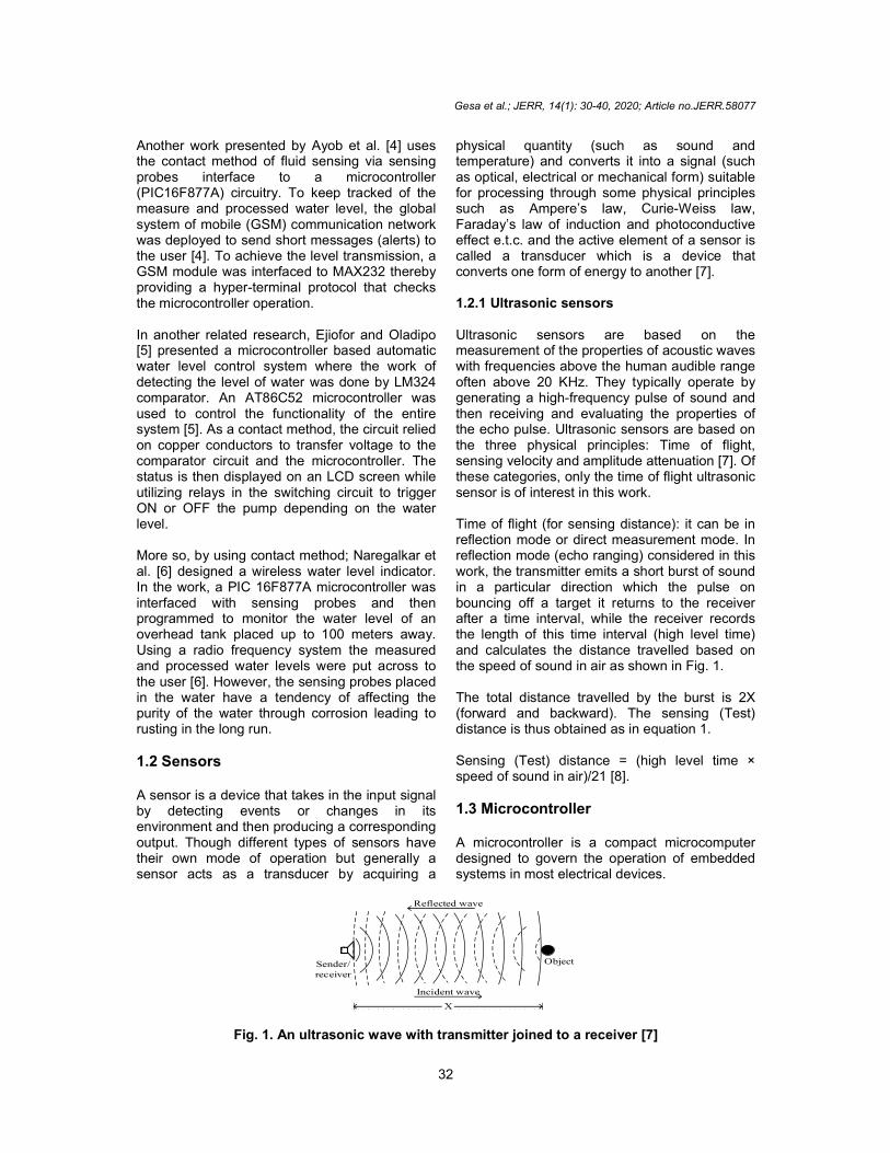
physical quantity (such as sound and temperature) and converts it into a signal (such as optical, electrical or mechanical form) suitable for processing through some physical principles such as Ampere’s law, CurieWeiss law, Faraday’s law of induction and photoconductive effect e.t.c. and the active element of a sensor is called a transducer which is a device that converts one form of energy to another [7]. 1.2.1 Ultrasonic sensors Ultrasonic sensors are based on the measurement of the properties of acoustic waves with frequencies above the human audible range often above 20 KHz. They typically operate by generating a highfrequency pulse of sound and then receiving and evaluating the properties of the echo pulse. Ultrasonic sensors are based on the three physical principles: Time of flight, sensing velocity and amplitude attenuation [7]. Of these categories, only the time of flight ultrasonic sensor is of interest in this work. Time of flight (for sensing distance): it can be in reflection mode or direct measurement mode. In reflection mode (echo ranging) considered in this work, the transmitter emits a short burst of sound in a particular direction which the pulse on bouncing off a target it returns to the receiver after a time interval, while the receiver records the length of this time interval (high level time) and calculates the distance travelled based on the speed of sound in air as shown in Fig. 1. The total distance travelled by the burst is 2X (forward and backward). The sensing (Test) distance is thus obtained as in equation 1. Sensing (Test) distance = (high level time × speed of sound in air)/21 [8].
1.3 Microcontroller A microcontroller is a compact microcomputer designed to govern the operation of embedded systems in most electrical devices.
X
Sender/receiver
Incident wave
Object
Reflected wave
Fig. 1. An ultrasonic wave with transmitter joined to a receiver [7]
Gesa et al.; JERR, 14(1): 30-40, 2020; Article no.JERR.58077
33
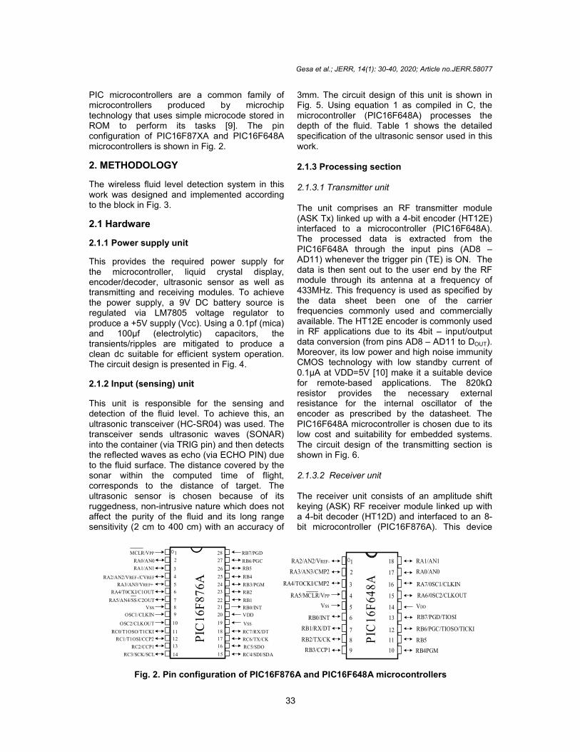
PIC microcontrollers are a common family of microcontrollers produced by microchip technology that uses simple microcode stored in ROM to perform its tasks [9]. The pin configuration of PIC16F87XA and PIC16F648A microcontrollers is shown in Fig. 2.
2. METHODOLOGY
The wireless fluid level detection system in this work was designed and implemented according to the block in Fig. 3.
2.1 Hardware
2.1.1 Power supply unit
This provides the required power supply for the microcontroller, liquid crystal display, encoder/decoder, ultrasonic sensor as well as transmitting and receiving modules. To achieve the power supply, a 9V DC battery source is regulated via LM7805 voltage regulator to produce a +5V supply (Vcc). Using a 0.1pf (mica) and 100µf (electrolytic) capacitors, the transients/ripples are mitigated to produce a clean dc suitable for efficient system operation. The circuit design is presented in Fig. 4. 2.1.2 Input (sensing) unit This unit is responsible for the sensing and detection of the fluid level. To achieve this, an ultrasonic transceiver (HCSR04) was used. The transceiver sends ultrasonic waves (SONAR) into the container (via TRIG pin) and then detects the reflected waves as echo (via ECHO PIN) due to the fluid surface. The distance covered by the sonar within the computed time of flight, corresponds to the distance of target. The ultrasonic sensor is chosen because of its ruggedness, nonintrusive nature which does not affect the purity of the fluid and its long range sensitivity (2 cm to 400 cm) with an accuracy of
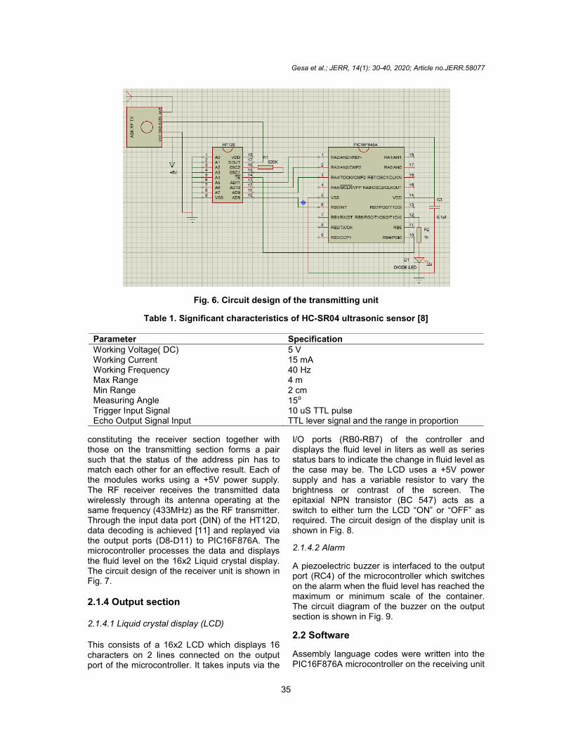
3mm. The circuit design of this unit is shown in Fig. 5. Using equation 1 as compiled in C, the microcontroller (PIC16F648A) processes the depth of the fluid. Table 1 shows the detailed specification of the ultrasonic sensor used in this work. 2.1.3 Processing section 2.1.3.1 Transmitter unit The unit comprises an RF transmitter module (ASK Tx) linked up with a 4bit encoder (HT12E) interfaced to a microcontroller (PIC16F648A). The processed data is extracted from the PIC16F648A through the input pins (AD8 – AD11) whenever the trigger pin (TE) is ON. The data is then sent out to the user end by the RF module through its antenna at a frequency of 433MHz. This frequency is used as specified by the data sheet been one of the carrier frequencies commonly used and commercially available. The HT12E encoder is commonly used in RF applications due to its 4bit – input/output data conversion (from pins AD8 – AD11 to DOUT). Moreover, its low power and high noise immunity CMOS technology with low standby current of 0.1µA at VDD=5V [10] make it a suitable device for remotebased applications. The 820kΩ resistor provides the necessary external resistance for the internal oscillator of the encoder as prescribed by the datasheet. The PIC16F648A microcontroller is chosen due to its low cost and suitability for embedded systems. The circuit design of the transmitting section is shown in Fig. 6. 2.1.3.2 Receiver unit The receiver unit consists of an amplitude shift keying (ASK) RF receiver module linked up with a 4bit decoder (HT12D) and interfaced to an 8bit microcontroller (PIC16F876A). This device
RB7/PGD
RB6/PGC
RB5
RB4
RB3/PGM
RB2
RB1
RB0/INT
VDD
VSS
RC7/RX/DT
RC6/TX/CK
RC5/SDO
RC4/SDI/SDA
PIC
16F
876A
1
2
3
4
5
6
7
8
9
10
11
12
13
14 15
16
17
18
19
20
21
22
23
24
25
26
27
28MCLR/VPP
RA0/AN0
RA1/AN1
RA2/AN2/VREF-/CVREF
RA3/AN3/VREF+
RA4/T0CKI/C1OUT
RA5/AN4/SS/C2OUT
VSS
OSC1/CLKIN
OSC2/CLKOUT
RC0/T1OSO/T1CKI
RC1/T1OSI/CCP2
RC2/CCP1
RC3/SCK/SCL
RA2/AN2/VREF-
PIC
16F
648
A
RA0/AN0
RA1/AN11
2
3
4
5
6
7
8
9
18
17
16
15
14
13
12
11
10
RA7/0SC1/CLKIN
RA6/0SC2/CLKOUT
RB7/PGD/TIOSI
VDD
RB6/PGC/TIOSO/TICKI
RB5
RB4PGMRB3/CCP1
RB2/TX/CK
RB1/RX/DT
RB0/INT
VSS
RA5/MCLR/VPP
RA4/TOCKI/CMP2
RA3/AN3/CMP2
Fig. 2. Pin configuration of PIC16F876A and PIC16F648A microcontrollers

Gesa et al.; JERR, 14(1): 30-40, 2020; Article no.JERR.58077
34
Fig. 3. Block diagram for the implementation of a wireless fluid level indicator
Fig. 4. Circuit design of the power supply unit
Fig. 5. Circuit design for the HC-SR04 ultrasonic transceiver
Gesa et al.; JERR, 14(1): 30-40, 2020; Article no.JERR.58077
35
Fig. 6. Circuit design of the transmitting unit
Table 1. Significant characteristics of HC-SR04 ultrasonic sensor [8]
Parameter Specification Working Voltage( DC) 5 V Working Current 15 mA Working Frequency 40 Hz Max Range 4 m Min Range 2 cm Measuring Angle 15⁰ Trigger Input Signal 10 uS TTL pulse Echo Output Signal Input TTL lever signal and the range in proportion
constituting the receiver section together with those on the transmitting section forms a pair such that the status of the address pin has to match each other for an effective result. Each of the modules works using a +5V power supply. The RF receiver receives the transmitted data wirelessly through its antenna operating at the same frequency (433MHz) as the RF transmitter. Through the input data port (DIN) of the HT12D, data decoding is achieved [11] and replayed via the output ports (D8D11) to PIC16F876A. The microcontroller processes the data and displays the fluid level on the 16x2 Liquid crystal display. The circuit design of the receiver unit is shown in Fig. 7.
2.1.4 Output section 2.1.4.1 Liquid crystal display (LCD)
This consists of a 16x2 LCD which displays 16 characters on 2 lines connected on the output port of the microcontroller. It takes inputs via the
I/O ports (RB0RB7) of the controller and displays the fluid level in liters as well as series status bars to indicate the change in fluid level as the case may be. The LCD uses a +5V power supply and has a variable resistor to vary the brightness or contrast of the screen. The epitaxial NPN transistor (BC 547) acts as a switch to either turn the LCD “ON” or “OFF” as required. The circuit design of the display unit is shown in Fig. 8.
2.1.4.2 Alarm
A piezoelectric buzzer is interfaced to the output port (RC4) of the microcontroller which switches on the alarm when the fluid level has reached the maximum or minimum scale of the container. The circuit diagram of the buzzer on the output section is shown in Fig. 9.
2.2 Software
Assembly language codes were written into the PIC16F876A microcontroller on the receiving unit

Gesa et al.; JERR, 14(1): 30-40, 2020; Article no.JERR.58077
36
while a C program was used in the PIC16F648A microcontroller on the transmitting unit to control and direct the operation of the device. The program for PIC16F648A was compiled in C due to its flexibility in execution of mathematical problems and calculations which is required to coordinate the ultrasonic sensor. The algorithms of the transmitting and receiving circuits are shown in Fig. 10 (a) and (b) respectively.
2.3 Level Calibration Using a tape rule, the distancetovolume calibration was done on the 30 cm height of the 20liter water tank of uniform crosssection. The calibration factor of 0.586 liter/cm was then obtained.
3. RESULTS AND DISCUSSION 3.1 Power Supply Test
The +5V regulated power source built for the circuits was tested at voltage –NoLoad and voltageOnLoad. The percentage voltage regulation shows a good result suitable for optimum system operation. The result of the test is presented in Table 2.
Percentage voltage Regulation =
∗ 100= 1.8%
3.2 Sensor Test
The sensor was mounted on a 30 cmtall tank containing 17 liters of water at full depth. The water level was then varied continually to a sensing distance of 29 cm. The change in volume as detected and transmitted by the
sensor (HCSR04) was continually read and recorded as shown in Fig. 11. Efforts were made to minimize the error due to blind zone or range. The area between the sonic transducer surface and the beginning of the detection range is called blind zone and must always be kept free [12]. This is a salient limitation of diffuse mode ultrasonic sensors as they are not capable of detecting targets which are located directly in front of the ultrasonic transducer. In this work, the blind range of 3 cm was excluded by pegging the maximum level of measurement on the 3rd cm mark down the tank. For this reason, the 30cmdeep container was only tested through 27cm marked range translating to maximum volume measurement of 17 liters as shown in Fig. 11. The result shows good linearity and output stability of the sensor over the tested range of time. The result hence conforms to the predefined algorithm coded in the microcontroller unit.
3.3 RF Module Test The RF module was tested to validate the maximum transmission distance. As such, a maximum transmission distance of 98.5 meters was observed in nonobstructed areas and 50.0 meters in obstructed areas respectively.
3.4 Summary The design and implementation of a wireless fluid level display system using ultrasonic sensing technique has been achieved and tested. The overall perform of each unit has proven the device as a viable tool suitable for fluid level sensing in both domestic and industrial uses.
Fig. 7. Circuit design of the receiving unit

Gesa et al.; JERR, 14(1): 30-40, 2020; Article no.JERR.58077
37
Fig. 8. Circuit design of the LCD unit
Fig. 9. Circuit design of the buzzer unit
(a) (b)
Fig. 10. Flow chart for (a) transmitting unit and (b) receiving unit

Gesa et al.; JERR, 14(1): 30-40, 2020; Article no.JERR.58077
38
Table 2. Test results for the regulated power supply
Specified voltage (LM7805) 5.00V VoltageNoLoad 4.99V VoltageFullLoad 4.90V
Fig. 11. Readings from sensor test
4. CONCLUSION
The microcontrollerbased wireless fluid level display system using ultrasonic sensing technique was successfully designed and implemented. Compared with other conventional designs; the wireless fluid level controller shows good performance and is more effective, reliable and cheap. The system is designed in such a way that it will be able to prevent the wastage of water and transmits the different water levels wirelessly to a receiver system placed some distances away from the containing vessel. The whole system operates automatically and thus; does not need manual intervention compared to other conventional contact methods of water level monitoring. It is noteworthy that moisture (humidity) has minimal effect (0.036% / 10% RH change) on ultrasonic sensors unlike photoelectric sensors. Hence the model used in this work is designed to withstand the harsh outdoor environment with full epoxy potting, UV shielded cables and stainless steel housing. To avoid cases of fluid spill when filling of tank, overflow control pipes or automatic ON/OFF circuit could be included to control the pump with respect to maximum desired fluid level thereby forestall any case of spillage which could affect the performance of the sensor.
COMPETING INTERESTS Authors have declared that no competing interests exist.
REFERENCES 1. Franco Maloberti, Anthony C. Davies,
editors. A Short History of Circuits and Systems; 2016. [ISBN: 9788793379701 (Paperback) 9788793379718 (Hardback) 9788793379695]
2. Gaur RK, Gupta SL. Engineering Physics. 1981: pp 54, Reviewed 2014. Ish Kapur for Dhanpat R.
3. Reza SM, Shah A, Tariq SM, Reza M. Microcontroller based automated water level sensing and controlling: Design and Implementation Issue, Proceedings of the World Congress on Engineering and Computer Science. 2010;1:220224.
4. Ayob J, Mohd HA, Nur SL, Ayob EM, Ayob IM, Ayob AM, Mohd NH. Tank water level monitoring system using gsm network. (IJCSIT) International Journal of Computer Science and Information Technologies. 2011;2(3):11141120.
5. Ejiofor VE, Oladipo OF. Microcontroller based Automatic Water level Control System, International Journal of Innovative Research in Computer and Communication Engineering. 2013;1(6): 13901396.
6. Naregalkar PR, Nishtha J, Parag V, Piyush B. Wireless water level indicator and controller using PIC microcontroller. International Journal of Current Research. 2016;8(02):2668026683.
0
5
10
15
20
0 10 20 30 40
Vo
um
e o
f w
ater
/Lit
res
Sensing distance/cm
3 c
m g
ap f
or
blin
d r
ange
Gesa et al.; JERR, 14(1): 30-40, 2020; Article no.JERR.58077
39
7. Regtien PPL. Sensors for mechatronics. Elsevier, USA; 2012.
8. Elijah J. Morgan. HCSR04 Ultrasonic Sensor; 2014.
9. Microcontroller chip Technology. PIC16F87XA Datasheet; 2001. Available:www.microchip.com
10. Holtek. HT12A/HT12E Data Sheet for 212 Series of Encoders. 2000. Retrieved On 12th January; 2017.
11. Holtek. HT12D/HT12F Data sheet for 212
Series of Decoders. 1999. Retrieved on 12
th January; 2017
12. Álvaro Hernández, Jesús Ureña, Manuel Mazo, Juan J. García, Ana Jiménez, Fernando J. Álvarez. Reduction of blind zone in ultrasonic transmitter/receiver transducers. Sensors and Actuators A: Physical. 2007;133(1).
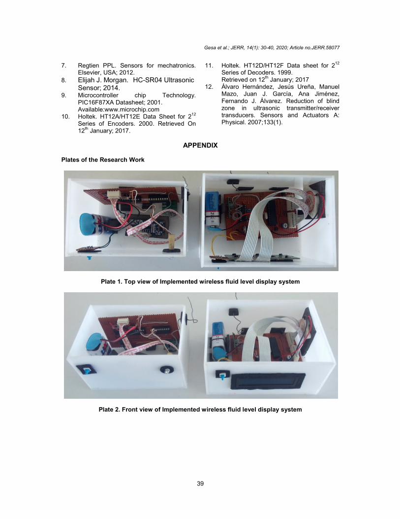
APPENDIX Plates of the Research Work
Plate 1. Top view of Implemented wireless fluid level display system
Plate 2. Front view of Implemented wireless fluid level display system
Gesa et al.; JERR, 14(1): 30-40, 2020; Article no.JERR.58077
40
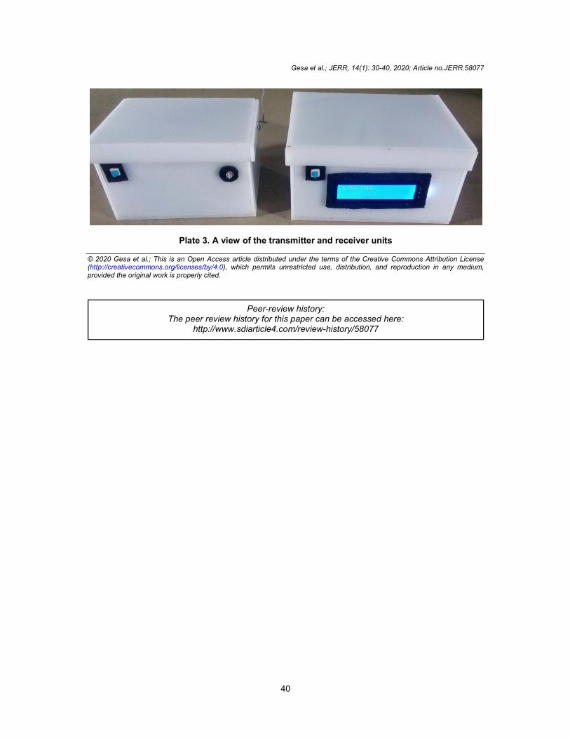
Plate 3. A view of the transmitter and receiver units
© 2020 Gesa et al.; This is an Open Access article distributed under the terms of the Creative Commons Attribution License (http://creativecommons.org/licenses/by/4.0), which permits unrestricted use, distribution, and reproduction in any medium, provided the original work is properly cited.
Peer-review history: The peer review history for this paper can be accessed here:
http://www.sdiarticle4.com/review-history/58077