Design and Experimental Investigation of a Novel Skip Cycle ...
32
Design and Experimental Investigation of a Novel Skip Cycle Mechanism Fırat Mehmet Günkan ( [email protected] ) Istanbul Teknik Universitesi https://orcid.org/0000-0003-2754-4852 Cemal Baykara Istanbul Teknik Universitesi Osman Akın Kutlar Istanbul Teknik Universitesi Original Article Keywords: valve control, skip cycle mechanism, skipcycle strategy, cam design, cycle optimization Posted Date: May 14th, 2020 DOI: https://doi.org/10.21203/rs.3.rs-24146/v1 License: This work is licensed under a Creative Commons Attribution 4.0 International License. Read Full License
-
Upload
khangminh22 -
Category
Documents
-
view
4 -
download
0
Transcript of Design and Experimental Investigation of a Novel Skip Cycle ...

Design and Experimental Investigation of a NovelSkip Cycle MechanismFırat Mehmet Günkan ( [email protected] )
Istanbul Teknik Universitesi https://orcid.org/0000-0003-2754-4852Cemal Baykara
Istanbul Teknik UniversitesiOsman Akın Kutlar
Istanbul Teknik Universitesi
Original Article
Keywords: valve control, skip cycle mechanism, skipcycle strategy, cam design, cycle optimization
Posted Date: May 14th, 2020
DOI: https://doi.org/10.21203/rs.3.rs-24146/v1
License: This work is licensed under a Creative Commons Attribution 4.0 International License. Read Full License

Design and Experimental Investigation of aNovel Skip Cycle Mechanism
Firat Mehmet Gunkan*1, Cemal Baykara1, and Osman Akin Kutlar1
1 IntroductionThe daily fuel consumption of spark ignition engines is approximately one third of world fuelproduction. It is thought that petroleum reserves will not need to demand in the near future.Consumption of oil reserves beside exhaust emissions and air pollution which increase becauseof the increasing number of passenger cars, reveals the importance of fuel consumption at in-ternal combustion engines. Nowadays, the effective efficiency of a internal combustion engineis about 35-40%, in the partial load area is approximately 10-15%. The most important reasonof this is the pumping losses. Today, different methods are applied to increase the efficiencyin the partial load area. The most important of these methods are variable valve timing [1],variable compression ratio [2], supercharging, variable stroke volume.A new working method for internal combustion engines, skip cycle strategy, which were re-vealed by Kutlar in 1999 has similarities with the cylinder deactivation systems, but it also hasadvantages especially in the application to single cylinder engines. As well as the multi cylindersystems the skip cycle strategy is a method of reducing the power taken by the engine, in otherwords, reducing the pumping losses in the partial load area. However, instead of disabling acertain number of cylinders, such as in the variable stroke volume method, each cylinder isintended to inactivate and activate each other in successive cycles [3]. With this method, fuel
([email protected]) ([email protected]) ([email protected])1Faculty of Mechanical Engineering, Istanbul Technical University,
Gumussuyu 34437, Istanbul, Turkey*Corresponding Author
Abstract
The main problem in near future is to increase the efficiency of internal combustion engines, which is the most important cause of air pollution in cities and the reduction of exhaust emissions from these engines. When operating conditions are examined in passenger cars, which are the main users of internal combustion engines, it has been seen that high fuel consumption occurs in the partial load area. A new working method for internal combustion engines, skip cycle strategy, which were revealed by Kutlar in 1999 has similarities with the cylinder deactivation systems, but it also has advantages especially in the application to single cylinder engines. The skip cycle strategy is a method of reducing the power taken by the engine, in other words, reducing the pumping losses in the partial load area. In this work, the control process has been provided according to cycle conditions and depending on skip cycle system needs, besides the mechanical valve control. The created mechanism consists of two groups: lock system and control system. In this study, the kinematic analysis of the engine has been carried out and the loads acting on the system have been determined. Finally, mechanism has been manufactured and experiments have been carried out at different speeds according to the NS (Normal cycle-Skip cycle) method, which is one of the several skip cycle strategies.
Keywords: valve control, skip cycle mechanism, skipcycle strategy, cam design, cycle optimization

and air intake are blocked in some of the successive cycles when the engine load is reduced,it should be increase the fill intake to achieve the same power. Thus, an increase in effectiveefficiency is expected. But the most important problem is that fuel blocking will not reducethe pumping losses in the cycle where the work is not produced. Therefore, the valves mustbe completely closed in order to prevent negative work in other words to prevent the air intakeinto the cylinder during intake time.Several mechanisms have been designed or are currently in use to control the valves in technicalliterature. Most of them have advantages and disadvantages according to working conditions.The BMW Valvetronic system developed by BMW [4][5], unlike normal system, consists of anextra arm and follower. In this system, the arm position provides the desired valve clearanceby controlling the rocker arm aperture. The control engine has been connected to the wormwheel and the worm gear depending on the arm. So that the position of the arm and thus thevalve control is provided. In the Valvelift system developed by Audi [6], the camshaft oper-ates according to the principle of position adjustment by entering the electronically controlledpins into the helical channels on the system. Thus, the valve is controlled by two differentcam profiles according to the condition of the engine. This system is more complicated thanother mechanisms. Variocam Plus system controls both variable valve timing and variable valveclearance. Control of this system is done hydraulically [7]. In Nagaya’s work [8], an inclinedcam profile controlled by a worm gear connected to the electric motor controls the valve withboth variable timing and variable valve opening operations performed at the same time. InEaton company mechanism, two-stage valve opening has been controlled by controlling nestedtwo cylindrical bodies with pins, externally [9]. The cylindrical spring between the two bodiesprovides the return motion. Another mechanism replaced in rocker arm was patented by Morita[10]. While this mechanism is also intended to be used in cylinder deactivation systems, it hasbeen determined that there is a gap of 0.12mm which leads to fill leakage. In Basshuysen’sstudy, a hydraulically controlled mechanism has been considered to be used for valve deactiva-tion process by placing it between the cam profile and the valve [11]. This mechanism bodyhas been specially designed to direct the fluid. This design has sealing problems relating tofluid leakage. In this work, the control process has been provided according to cycle conditionsand depending on skip cycle system needs, besides the mechanical valve control. The createdmechanism consists of two groups: lock system and control system. In this study, the kinematicanalysis of the engine has been carried out and the loads acting on the system have been de-termined. Finally, mechanism has been manufactured and experiments have been carried outat different speeds according to the NS (Normal cycle-Skip cycle) method, which is one of theskip cycle strategies.
2 Methodology
2.1 The Design of Skip Cycle MechanismIn the skip cycle system developed by Kutlar, the pumping losses will not be reduced in thecycle where the work will not be produced (or workless cycle) by cutting the fuel only. There-fore, the valves must be completely closed in order to prevent air entering the cylinder duringintake time. The mechanism consists of two main parts; the locking mechanism and the controlmechanism. Fig.1.The locking mechanism has been located just above the valve, so that it can be used in single-cylinder or multi-cylinder systems without any intervention to the cam and rocker arm mech-anism. In addition, the filler leakage on the valve are controlled due to the connection of thelock mechanism with the physical connection. It also allows the use of different cycle strategiesby controlling the lock mechanism with the help of pins.The control of the locking mechanism is carried out with control cams which are operated in

synchronism with the crankshaft and mechanically controlled. The mechanism is also designedto be able to respond to different strategies because there are more than one strategy in theskip cycle approach. The profiles of the control cams have been calculated according to theangular analysis of the crankshaft and the targeted strategy.In addition, the skip cycle system not only controls the intake valves but also the exhaustvalves.
Spring Holder
Control Pins
Locking Body
Control Mechanism
The Locking Mechanism
Original Engine
Figure 1: Skip Cycle Mechanism
2.2 Working Principle of Skip Cycle StrategySkip cycle mechanism prevents to open the valves so that no work is produced in the stageafter 4 cycles of power generation. There are two positions in the mechanism to prevent theopening of the valves: Position in which the valves are closed (locking mechanism disabled,skipped cycle) and valve open position (lock mechanism active, normal cycle).
2.2.1 Disabled Mode of Poppet ValveThe pusher pins, which get the movement from the controller cam, fixes the main spring holderto the cylinder head. Therefore, the lock body will be released into the main spring holder. Atthe same time, the camshaft transmits the motion from the system with the help of pushrodand the rocker moves downwards. The free lock body moves vertically in the spring holder.The rocker return motion is provided by an additional return spring in the locking system. Thevalve movement will be canceled in the lock position cycle, because the main spring holder to

which the valve is connected is fixed. (Fig. 2a)
2.2.2 Enabled Mode of Poppet ValveThe pin group receiving the return motion from the return cam is in the free position in thelock body. For this reason, the main spring holder and the cylinder head are separated fromeach other and locked with 3 points by the lock body. At the same time, the camshaft transmitsthe motion from the system with the help of pushrod and the rocker moves downwards. Theposition of the pusher pin group connects the lock body with the main spring holder, so thatthe main spring is moved downward by the rocker. The valve will move in the free positionsince the spring holder is attached to it. Thus, the cycle will be completed normally. (Fig. 2b).
Figure 2: a) Disabled mode (on left), b) Enabled mode (on right)
2.3 The Locking MechanismThe control of the mechanism has been provided by pins. When the positions of the pins areexamined, the rocker in the first position in Figure 3a will push the lock mechanism. Duringthis time, the valve will not open, and the cycle will be skipped. The other pins hold the mainspring holder, which is connected to the valve, by the shape connection, so that filler leaks willbe prevented. In Figure 3b, the lock body has been locked with the main spring holder pinsand the valves are opened, so normal cycling takes place.

Figure 3: a) Locking position (Skip Cycle), b) Unlocking position (Normal Cycle)
Spring holder body: It plays an important role in adjusting the position of pins and lockingposition. The positions and diameters of the control pins have been used to determine thedimensions of the planar region to prevent rotation of the main spring retainer about its axis.The lower part of the spring holder is closed. The oil must not accumulate during operationand the support parts must be lubricated. For this reason 6 oil drain holes with a diameter of2 mm have been opened in equal intervals around the main spring holder.Control Pins: They control the system by receiving movement from the control cam group.There are 5 pins in the system. When the positions of the pins are examined, the rocker inthe first position in Figure 3a will push the lock mechanism. During this time, the valve willnot open, and the cycle will be skip. The other pins hold by the shape connection the mainspring holder which is connected to the valve, so that filler leaks will be prevented. In Figure3b, the lock body has been locked with the main spring holder pins and the valves are opened,so normal cycling takes place.Pushing Cam: It controls the forward and backward control of the pins and the locking ofthe sphere. It is located in the lock body.Locking Body: It forms the body of all the elements used in the locking operation and allowsthe pins to bear when moving.
2.4 Control MechanismSpecially designed cam profiles for pins position control have been used. The engine used inthe experimental setup is a 4-stroke engine. Therefore, there is a ratio 1/4 between the controlcam and the crankshaft. The control cam profiles considering this conversion ratio have beendesigned according to the angle values given in Table 1 for the NS strategy. The NS and NSScontrol cam diagrams are given in the Figure 4
Control Cam Reverse CamRise 0-55 Dwell 0-125
Dwell1 55-180 Dwell1 55-180Fall 180-235 Fall 180-235
Dwell2 235-360 Dwell2 235-360
Table 1: Control Cam Parameters for NS Strategy

Figure 4: NS and NSS Strategy Control Cam Profiles
A 3-4-5 polydin cam equation has been chosen for the control cam motion equation. There aretwo symmetrical cams in the control cam group, which determine the position of the controlpins. The first one is named as the control pin and determines the position of the pins. Theother is called returning cam and brings the pins to the initial position Fig. 1. The controlcamshaft and the crankshaft must also be synchronized. Fig. 5. To this end, movement andpower transmission have been provided with a timing belt.
0 180 360 540 720 900 1080 1260 1440
Skip cycle
Normal cycle
Active parts Locked side
Figure 5: Mechanism positions in Normal and Skip cycle strategies

3 Engine Load AnalysisThe valve control mechanism has been designed for a single-cylinder test engine as shown inFig.6. It has been modified and converted into a gasoline engine, which is used as the testengine. The camshaft of this engine OHV (Over Head Valve): The valve has been mounted onthe cylinder head. The valve has been controlled according to the special profiles on the camshaft which receives movement from the crankshaft. There are three different profiles on thecamshaft. One of them controls the intake valve, while the second for the exhaust valve. Themiddle one controls the diesel pump. This profile will not be used during experiments becausethe test engine has been converted to a gasoline engine.The camshaft transmits the circular motion from crankshaft to the valve tappet with the helpof the profiles. The push rod is placed at the bottom of the tappet valve with a spherical joint.It is articulated to the adjusting screw at the top and transmits the linear motion to the rockerarm. There must be a gap between cylinders and valves, according to the type and design of theengine. The test engine has a valve clearance of 0,2 mm. This clearance is determined by theposition of the adjusting screw. The rocker transmits the movement to the valve by changingthe ratio of the distance between the arms. When the valve part is examined, a structuremounted on a prestressed torsion spring is seen. In addition, these springs have a high springcoefficient that allows to contact between tappet valve and cam profile when the mechanism isat high speeds.
Figure 6: Test engine valve train mechanism
The magnitudes that affect the mechanism design depend on the inertia forces that are directlyproportional to the acceleration. Acceleration depends on the cam profile, in other words, itis related to the motion equation of cam. Many curves are used to determine cam profiles.Calculations of harmonic, parabolic and cycloid curves are easy. However, considering the

information obtained from the technical drawings and the characteristics of the test engine,these curves have been seen inadequate at high speeds. In such cases, advanced curves areused. In this study, ”Polidin” curves developed by Dudley (1952) have been used when thecharacteristics of the test engine were taken into consideration [12]. Differential equations havebeen used in the solution of motion equations and follower in the polydin curves.The polynomial curve equation to be used represents only one side (positive angle values) ofthe cam profile. The negative values of the cam angle (θ) have to be calculated with referenceto the maximum displacement point in order to draw for the symmetrical second side. Solutionequation is obtained by using 6 boundary conditions for 3-4-5 polynomial equations. Theequation giving the general definition of the polynomial curves is used in order to obtain it((1)).
y = 1− 10θ3 + 15θ4 − 6θ5
y′ = −30θ2 + 60θ3 − 30θ4
y′′ = −60θ + 180θ2 − 120θ3(1)
It has been determined that the cam lift actuating the intake valve is 6.55 mm. This maximumdisplacement takes place at an angle of 140◦. The cam lobe climbs between 0◦ and 70◦, while itgoes down between the angles of 70◦-140◦. Taking these values into consideration, the equationof motion 3-4-5 is multiplied by the expression 6.55/70n to obtain the equation of motion ofthe intake cam lobe of the test engine. Fig.7.
y = 6, 55− 65, 5
[
θ
70
]3
+ 98, 25
[
θ
70
]4
− 39, 3
[
θ
70
]5
y′ = −2, 8
[
θ
70
]2
+ 5, 61
[
θ
70
]3
− 2, 8
[
θ
70
]4
y′′ = −0, 08
[
θ
70
]
+ 0, 24
[
θ
70
]2
− 0, 16
[
θ
70
]3
(2)
Figure 7: Engine Cam diagrams

The maximum force is obtained when the valve spring is in its maximum compression state.In force analysis, it is also necessary to include the inertia of the rocker in the system. Thisinertia will not be equal due to the difference in lift between the two rocker arms. The easiestway to carry out calculations is to determine the valve equivalent mass on the valve side. Thesystem has been considered to be a two-mass model with a suitable size and position. Fig.8.
Figure 8: Rocker arm two mass model
The system should produce reaction forces equal to the system forces. In the kinetic equivalentsystem shown in Fig.8, m represents mass, IG is the moment of inertia with respect to thecenter of gravity, m1 and m2 are the mass in two-mass equivalent system, and h1 and h2 denotethe distance from the center of gravity of equivalent masses.
m1 +m2 = m (3)
m1 · h1 = m2 · h2 (4)
m1 · h2
1+m2 · h
2
2= m · k2 (5)
If it is written the equation (4) into the equation (5), it is found
m1 · h2
1+m2 · h1 · h2 = m · k2 = IG (6)
Here, k is the radius of inertia with respect to the center of gravity . Mass on the cam side,
m1 =m · k2
h1 · (h1 · h2)(7)

Using equations (3) and (4), the simplest form
m1 =m · h2
h1 + h2
(8)
Inertia radius,
k2 = h1 · h2 (9)
The masses of the system elements have been weighed on the sensitive scale in force analysis(Table 2). Because all the elements in the valve mechanism have linear motion, the masses willbe added directly to the force calculation. Since the rocker makes circular motion, the mass willbe detected by performing a two-mass reduction. The system has been examined separately onthe valve side and on the cam side, due to the size difference between the rocker arms.
Rocker arm 95,88 grSet Screw 7,25 grPusher 123,47 grRod 45,75 gr
Follower 13,61 grValve(i) 52,26 grValve(e) 45,22 gr
Rocker arm Shaft 68,21 grValve Claw 1,29 gr
Table 2: The masses of the system elements
The total mass in the cam side is valve tappet, push rod, setting nut, follower. Using theequation(8), if the mass of the camber on the cam side is reduced, m1 is found equation(8) Thetotal mass, along with the mass of the other elements, is found equation(8). The principle ofD’Alembert, based on Newton’s second principle, has been used in the force analysis. Forcemagnitudes on the cam side and on the valve side are shown between 0◦ and 70◦ in Fig.9. Asa result of the analytical analysis performed, a maximum force of 154 N has been determined.
Figure 9: Variable load on valve analytical analysis result

3.1 Stress and Fatigue AnalyzesSkip cycle mechanism performs valve control in two different phases. In the case where themechanism is active, the normal cycle is carried out, the cycle is skipped when the mechanismis deactivated. The mechanism can be controlled as a normal cycle and skip cycle by means of5 pin movements in the lock body.
The load affects on the two pins in the skip cycle. In the normal cycle, the load is applied tothree points, which are two pins and sphere. The pins have been located in the cylinder head,the spring retainer and the lock body for operation of the system. Therefore, the toleranceand operating conditions of the pins are very important. Looking at the locking pins and thesphere geometry , it can be seen that their sections are circular. There is cutting effect atthree different points in locking pin assembly. Since the area under this effect is circular, themaximum stress will be in the neutral axis.
τmax =4
3·F
A·1
3≤ τallow (10)
The total force acts as 1/3 of the total load for each pin, since the locking is made (occured)with 3 pins. The pins whose task is controlling and locking in the system have been loaded50 times in a sec at 1500 d/d. Therefore, life calculations have been made in addition to thestrength calculation of these pins. Fatigue analysis has been performed with a high conversionratio. If we look at the security factor result in 9 to 1 cycle (Fig.10a), a minimum value is 1,952.This value is above 1, so it is safe for 9 to 1 cycles. In the next stage, fatigue sensivity graph(Fig.10b) shows the behavior of the load with 50% load and 400% load. There is no securityproblem in life even at 400% load as shown in graph.
Figure 10: Fatigue analysis results - a) Safety factor, b) Fatigue sensitivity
4 Experimental Testing of the Skip Cycle MechanismThe single-cylinder diesel engine has been chosen as the experimental engine. Because, it hasfewer parts and the measurements are suitable for the experiment. Its characteristics are shownin Table 3. Firstly, experiment has been carried out with an electric engine. A 35.5 mm piecehas been added to the cylinder head so that the valve control mechanism could be placed on thesystem. Thus, it has been adapted to the experimental engine without being interfered withthe mounting points. When testing the electric engine, the crankshaft has been manufacturedas a flat shaft in order to avoid the balancing problem (Fig. 11). The number of revolutions ofthe electric motor has been controlled by the motor driver.

Number of cylinders 1Bore&Stroke 85 mm x 80 mmCompression Ratio 17,5:1Power 7 KW @ 3000 rpmTorque 28,5 Nm @ 1700 d/dIntake valve dia 32 mmIntake valve lift 10,55 mmIntake valve opening 16◦ CA BTDCIntake valve closing 40◦ CA ATDCExhaust Valve dia 27 mmExhaust valve lift 10,55 mmExhaust valve opening 40◦ CA BBDCExhaust valve closing 16◦ CA ATDC
Table 3: Test engine specifications
Figure 11: Simplified crankshaft
In the experimental setup, the engine has been driven by an electric motor connected to theV-belt pulley. The AC motor drive has been used to control the number of revolutions of theAC electric motor and to respond more quickly to possible mechanism lockouts Fig. 12. Inaddition, the experimental setup has been recorded with a high-speed camera.

Motor Driver
Electric Motor
Figure 12: Experiement Set-up
Testing of the mechanism has been carried out in three stages.
1. The pins are at the normal cycle position and can only be operated in normal cycle.2. The pins are at the skip cycle position and operate in the skip cycle.3. Testing the system with a cam profile with NS strategy.
In the first step, the timing belt, which provides transmission between the crankshaft andthe control camshaft, has been removed and the position of the pins has been adjusted to bethe normal cycle. The number of revolutions has been increased from 300 rpm to 1200 rpmwith the aid of the potentiometer on the AC motor drive, and the mechanism has been tested(Figure 13). The first stage test has been completed in about 15 minutes with parts control. Inthe second stage, the position of the pins is in the skip cycle position. The number of revolutionshas been increased from 300 rpm to 1200 rpm with the aid of the potentiometer on the ACmotor drive, and the mechanism has been tested (Figure 14). Mechanism elements deformationhas been checked, as a result of these two tests.
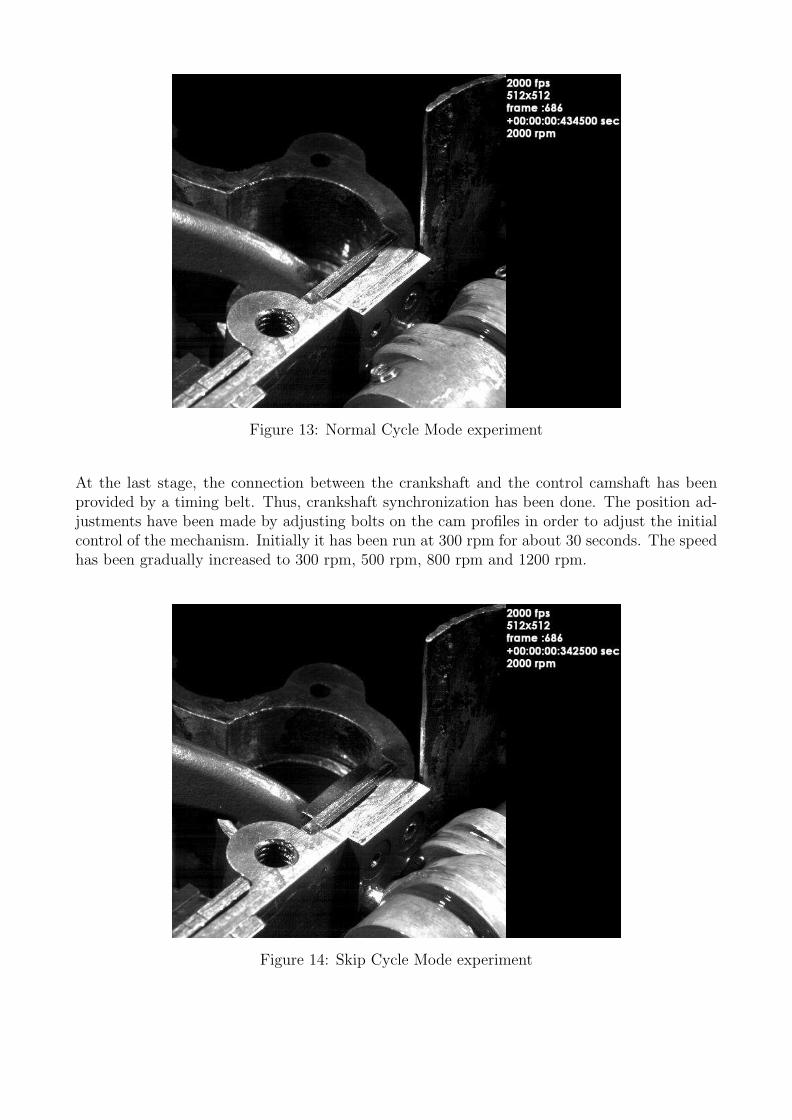
Figure 13: Normal Cycle Mode experiment
At the last stage, the connection between the crankshaft and the control camshaft has beenprovided by a timing belt. Thus, crankshaft synchronization has been done. The position ad-justments have been made by adjusting bolts on the cam profiles in order to adjust the initialcontrol of the mechanism. Initially it has been run at 300 rpm for about 30 seconds. The speedhas been gradually increased to 300 rpm, 500 rpm, 800 rpm and 1200 rpm.
Figure 14: Skip Cycle Mode experiment

5 ConclusionsIn this work, the valve locking mechanism has been designed and prototyped for the skip cycle mechanism introduced in 1999 by Kutlar. The design of the mechanism consists of two main parts (the locking mechanism and the control mechanism), which is very important in terms of the suitability of Kutlar to different strategies (NS, NSS, NNS etc.) In addition, filler leaks have been prevented by mechanical locking. The experimental engine has been solved kinematically and the data obtained from this analysis has been used in mechanism design. Alternative changes on the design can be seen quickly in the analyzes because all designs are created in 3D. Dynamic simulations have been performed with real parameters and the problems of the systems obtained from these simulations have been determined so that appropriate solutions for these problems have been tried to be found in the new design. It has been determined that the materials of the mechanism parts are appropriate as a result of static and fatigue analyzes.] The system is flexible because the mechanism has been designed to fit many different strategies. An experimental setup has been established in Istanbul Technical University Automotive Laboratory, and the assembly has been completed and experiments have been carried out. It has been determined that the mechanism works smoothly as a result of the experiments. In addition, the test engine has been connected to the electromagnetic brake; therefore, fuel consumption values have been obtained when only the intake valve is controlled.
First prototype engine was equipped with an additional rotary valve at intake channel driven by a rotary solenoid. During skipping cycle, rotary valve is closed, fuel injection and ignition is cut off. There was not any intervention to control the inlet and exhaust poppet valves. Experi-mental results on engine dynamometer shows that rotary valve in intake channel could not hold back completely the flow into the combustion chamber. This results with a loss of fresh charge during skipping cycle, consequently increasing HC emissions and fuel consumption. It was only possible at very low loads and in NSS working condition to reduce the fuel consumption.
Second prototype engine was equipped with a mechanism, which allows pushing and pulling back the eccentric shaft hence via disconnecting the cam fallower, deactivating the inlet and exhaust valves during skipping cycle. If the mechanism is mounted the engine runs only with one skip cycle (NS) without the ability to changing the working cycles like normal four stroke or two skipping cycle (NSS). Experimental results on engine dynamometer shows that the mechanism could stop fully the charge exchange between combustion chamber and inlet- exhaust-channels during skipping cycle. With one skip cycle (NS) it was possible to reduce the fuel consumption and pumping losses during gas exchange, in comparison to normal four stroke working conditions at low load regimes. At load conditions between 1-3 bar brake mean effective pressure (BMEP-pme) fuel consumption reduction was between 14-26%. Table 4. Figure 15)

-5
0
5
10
15
20
25
30
35
40
45
50
0 180 360 540 720 900 1080 1260 1440
Ba
r
KMA
Pme = 3 bar, n = 1800 d/d
Normal-Skip cycle
Normal-Normal cycle
Figure 15: Experiment Results
The subject of this article is to develop a mechanism, which allows the transition betweenworking modes. Mentioned working modes may be normal four-stroke cycle, one normal andone skipping cycle (NS), one normal and two skipping cycle (NSS) etc. which can be expandeddepending on load condition, applied strategy and design of mechanism.[13]
pme = 1bar pme = 2bar pme = 3barn (d/d) N NS Diff. % N NS Diff. % N NS Diff. %1200 1055 780 -26 587 485 -17 491 404 -181350 927 731 -21 565 483 -14 484 400 -171500 913 722 -21 564 478 -15 477 396 -171650 905 695 -23 561 475 -15 475 398 -161800 939 777 -17 581 486 -16 477 395 -17
Table 4: Experimental results

6 Declarations
Availability of data and materials : The authors confirm that the data supporting the findings of this study are available within the article [and/or] its supplementary materials.
Competing interests : Not applicable
Funding : Not applicable
Authors' contributions
Firat Mehmet Günkan: Conceptualization, Methodology, Software, Data curation, Writing- Original draft preparation,
Cemal Baykara: Conceptualization, Supervision, Writing- Reviewing and Editing, Validation
Osman Akin Kutlar: Conceptualization, Validation
Acknowledgements: Not applicable

References[1] Adam T.J.M. Rose, Sam Akehurst, and Chris J. Brace. Investigation into the trade-
off between the part-load fuel efficiency and the transient response for a highly boosteddownsized gasoline engine with a supercharger driven through a continuously variabletransmission. Proceedings of the Institution of Mechanical Engineers, Part D: Journal ofAutomobile Engineering, 227(12):1674–1686, 2013.
[2] A. Javaheri, V. Esfahanian, A. Salavati-Zadeh, and M. Darzi. Energetic and exergeticanalyses of a variable compression ratio spark ignition gas engine. Energy Conversion andManagement, 88:739–748, 2014.
[3] Alper Tolga Calik Osman Akin Kutlar, Hikmet Arslan. Methods to improve efficiencyof four stroke, spark ignition engines at part load. Energy Conversion and Management,46:3202–3220, 2005.
[4] Saeed A. Albatlan and Eid S. Mohamed. Dynamic analysis and experimental evaluation ofvariable valve lift system for internal combustion engine with double overhead camshaft.International Journal of Vehicle Structures and Systems, 6(1-2):24–31, 2014.
[5] Christoph Luttermann, Erik Schueenemann, and Norbert. Klauer. Enhanced VAL-VETRONIC technology for meeting SULEV emission requirements. Society of AutomotiveEngineers, [Special Publication] SP, SP-2025(Advanced Catalysts and Substrates 2006):7–11, 2006.
[6] Robert Huber, Peter Klumpp, and Heinz Ulbrich. Dynamic Analysis of the Audi ValveliftSystem. SAE International Journal of Engines, 3(1):2010–01–1195, 2010.
[7] Claus Brustle and Dietmar Schwarzenthal. VarioCam Plus - A Highlight of the Porsche911 Turbo Engine. SAE Technical Paper, 2001(724), 2001.
[8] Kosuke Nagaya, Hiroyuki Kobayashi, and Kazuya Koike. Valve timing and valve lift controlmechanism for engines. Mechatronics, 16(2):121–129, 2006.
[9] Eaton Corporation Beachwood. Variable valve actuation rocker arm assembly, 2014.
[10] Yasuyuki Morita. Engine Valve Mechanism Having Valve Disabling Device. 1984.
[11] Richard van Basshuysen. Cylinder deactivation and fading out of individual cycles to thefuel economy and exhaust emissions, 1993.
[12] W.M. Dudley. A New Approach to Cam Design. Machine Design, 184, 1952.
[13] Cemal Baykara, O. Akin Kutlar, Baris Dogru, and Hikmet Arslan. Skip cycle method witha valve-control mechanism for spark ignition engines. Energy Conversion and Management,146(March 2018):134–146, 2017.

Figures
Figure 1
Skip Cycle Mechanism
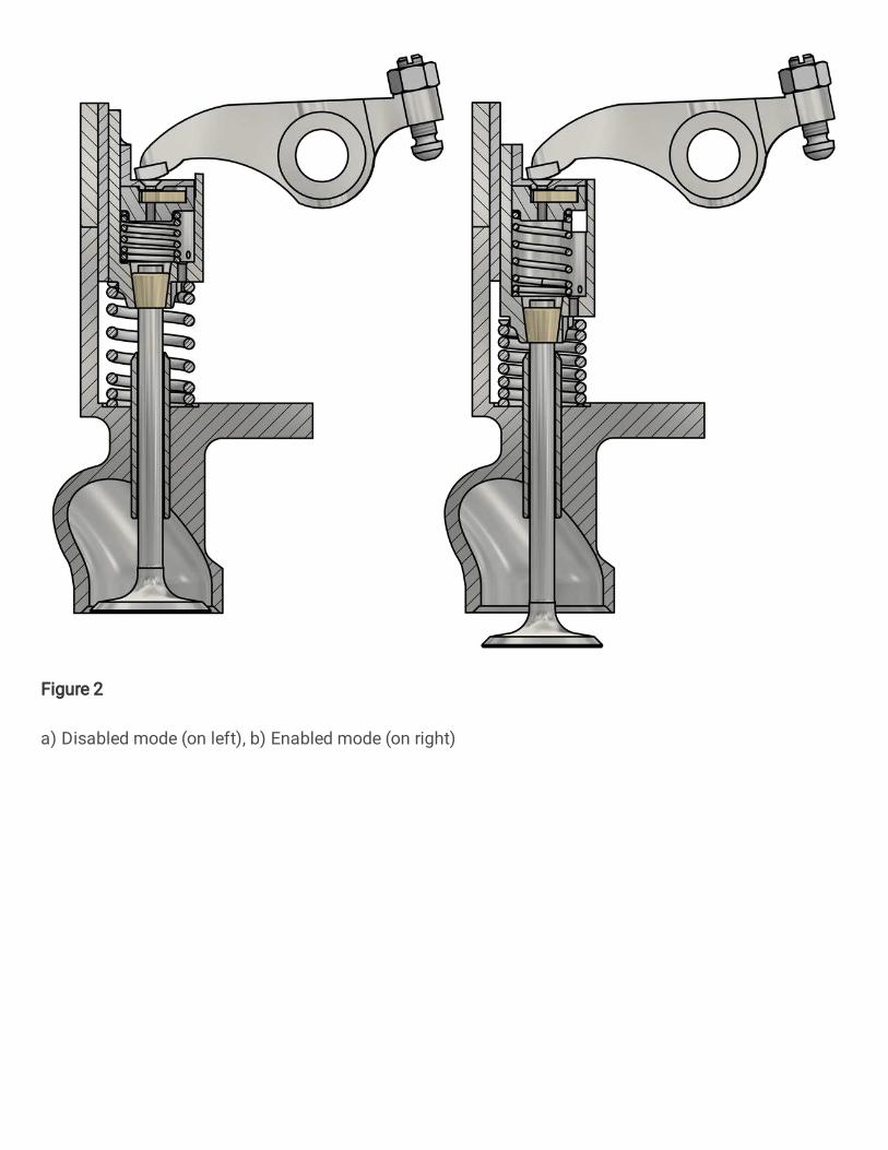
Figure 2
a) Disabled mode (on left), b) Enabled mode (on right)

Figure 3
a) Locking position (Skip Cycle), b) Unlocking position (Normal Cycle)

Figure 4
NS and NSS Strategy Control Cam Pro�les

Figure 5
Mechanism positions in Normal and Skip cycle strategies

Figure 6
Test engine valve train mechanism

Figure 7
Engine Cam diagrams

Figure 8
Rocker arm two mass model

Figure 9
Variable load on valve analytical analysis result
Figure 10
Fatigue analysis results - a) Safety factor, b) Fatigue sensitivity

Figure 11
Simpli�ed crankshaft
Figure 12
Experiement Set-up

Figure 13
Normal Cycle Mode experiment

Figure 14
Skip Cycle Mode experiment

Figure 15
Experiment Results