DESIGN AND CONVERSION OF A FOUR STROKE ENGINE ...
121
ESCUELA TÉCNICA SUPERIOR DE INGENIERÍA (ICAI) GRADO EN INGENIERÍA ELECTROMECÁNICA Especialidad Mecánica DESIGN AND CONVERSION OF A FOUR STROKE ENGINE TO A SIX STROKE ENGINE Autor: Alvaro Espejo Abela Director: Matthew McGarry Madrid Julio 2018
-
Upload
khangminh22 -
Category
Documents
-
view
3 -
download
0
Transcript of DESIGN AND CONVERSION OF A FOUR STROKE ENGINE ...

ESCUELA TÉCNICA SUPERIOR DE INGENIERÍA (ICAI)
GRADO EN INGENIERÍA ELECTROMECÁNICA
Especialidad Mecánica
DESIGN AND CONVERSION OF A FOUR
STROKE ENGINE TO A SIX STROKE ENGINE
Autor: Alvaro Espejo Abela
Director: Matthew McGarry
Madrid Julio 2018
1
2
3
4
ESCUELA TÉCNICA SUPERIOR DE INGENIERÍA (ICAI)
GRADO EN INGENIERÍA ELECTROMECÁNICA
Especialidad Mecánica
DESIGN AND CONVERSION OF A FOUR
STROKE ENGINE TO A SIX STROKE ENGINE
Autor: Alvaro Espejo Abela
Director: Matthew McGarry
Madrid Julio 2018
5
DISEÑO Y ADAPTACIÓN DE UN MOTOR DE CUATRO TIEMPOS A UNO
DE SEIS TIEMPOS
Autor: Espejo Abela, Álvaro
Director: McGarry, Matthew
Entidad Colaboradora: ICAI – Universidad Pontificia de Comillas, University of San Diego.
RESUMEN DEL PROYECTO
Introducción
El siguiente proyecto tiene como objetivo la investigación y el desarrollo de un motor de seis
tiempos. Dado la delicada situación de crisis energética mundial, este proyecto pretende diseñar y
crear un motor capaz de mejorar la eficiencia de los motores de cuatro tiempos actuales y que
consiga conservar las demás especificaciones. Los motores de hoy en día, aunque han mejorado
sustancialmente su eficiencia con el paso de los años, siguen teniendo una eficiencia muy baja (30-
40% en la mayoría de los motores de combustión y compresión) puesto que no deja de ser una
máquina térmica con elevadas pérdidas. El resto de la energía se entrega al ambiente por sistemas
de refrigeración de aire o agua, dependiendo del tipo de motor. Esta idea revolucionaria, basada
en el motor de seis tiempos diseñado por Bruce Crower, consiste en añadir dos tiempos adicionales
mediante la inyección de agua. El agua tiene dos funciones principales: la refrigeración y la entrega
de potencia al motor. El agua, al ser inyectada en el quinto tiempo, absorbe el calor del cilindro y
lo utiliza para cambiar de estado líquido a gaseoso. A temperatura ambiente, el agua es capaz de
expandirse 1600 veces el volumen que ocupa en su estado líquido. Esta expansión es la responsable
de entregar potencia durante el quinto tiempo del motor. Finalmente, la energía que el agua utiliza
para la expansión es energía térmica que se extrae durante el último ciclo o sexto ciclo, el de
escape. El propósito de este proyecto es adaptar un motor de la forma más fácil, eficiente y
económica posible. Además, se trata de responder a la siguiente pregunta: ¿Puede un motor de
seis tiempos mejorar la eficiencia de un motor de combustión actual?
Metodología
Para resolver el problema, la adaptación se dividirá en cuatro subsistemas principales: el inyector
de agua, el árbol de levas, el piñón de distribución y el motor base. En este proyecto se analizarán
diversas posibilidades para el diseño y obtención de los distintos subsistemas que componen el
motor. Antes de proceder a la elección final de cada subsistema, se hará un estudio termodinámico
para calcular la cantidad necesaria de agua que debe ser inyectada para que el motor opere en todo
su rango; un estudio mecánico estático y de fatiga para calcular el diámetro mínimo necesario para
el árbol de levas; y un estudio mecánico para el perfil del piñón de distribución del árbol de levas.
Tras el estudio teórico y teniendo en cuenta el presupuesto y demás factores determinantes, se
procederá a la elección de cada subsistema para finalmente integrarlos en un único motor.
Siguiendo la integración, se realizarán pruebas con el objetivo de averiguar si se ha producido un
incremento de la eficiencia en la forma de una reducción del consumo de combustible entregando
la misma potencia o una mayor entrega de potencia empleando el mismo combustible.
6
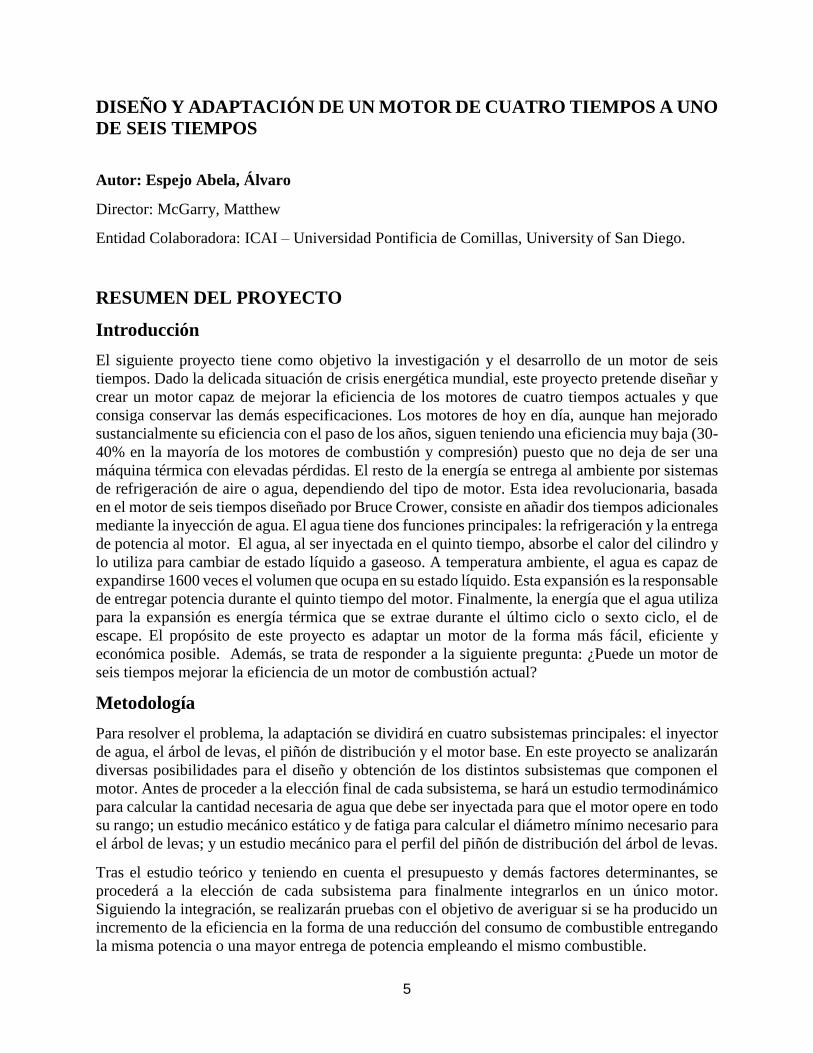
Soluciones Propuestas
Después de un amplio estudio de distintas soluciones para cada subsistema, se llegó a la siguiente
solución. En cuanto al motor base, la elección fue un motor motocicleta Honda XR250 de 250 cc,
OVC, de cuatro tiempos y refrigeración por aletas. Para el árbol de levas se decidió mecanizarlo
en la universidad, mientras que el piñón se encargó a la distribuidora McMaster Carr. Finalmente,
para la inyección del agua se desarrolló un sistema de inyección hidráulico mediante la
concatenación de una bomba hidráulica y diversas válvulas con distintas funciones.
Figura A: Sistema de Inyección de Agua Figura B: Piñón y Árbol de Levas.
Fuente: Elaboración Propia Fuente: Elaboración Propia
Figura C: Motor Honda XR250
Fuente: www.honda.com
7
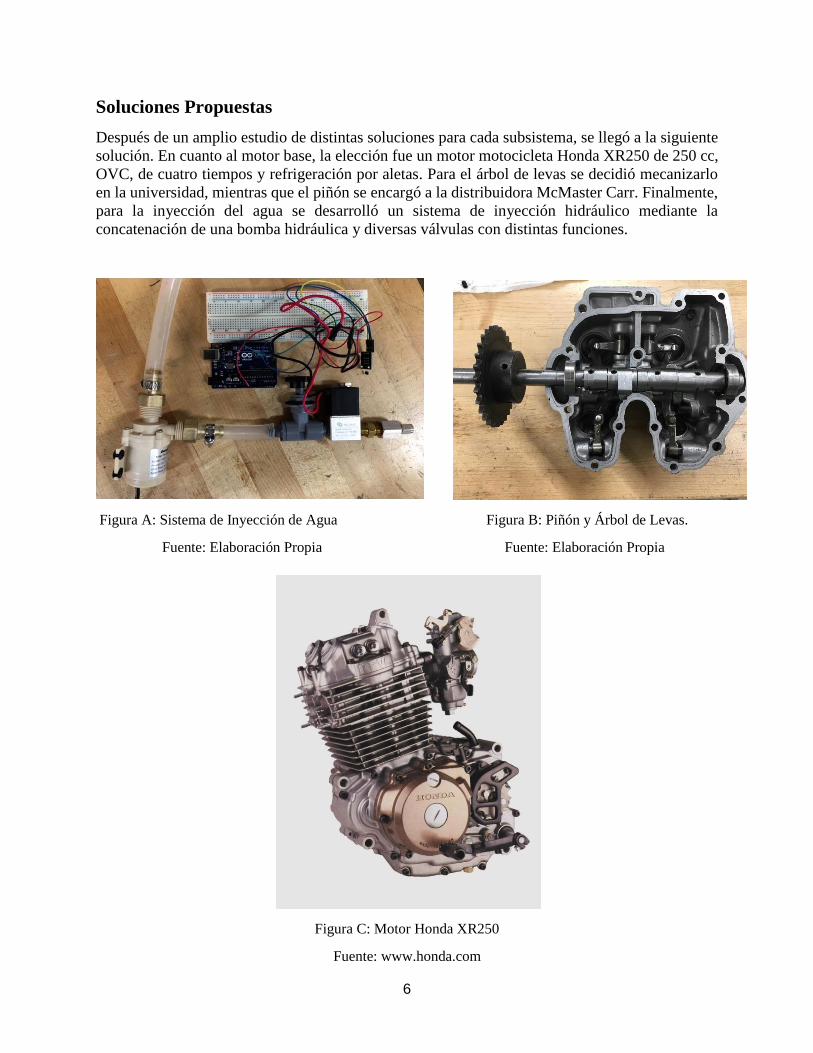
Resultados
Para este proyecto se obtuvieron resultados teóricos y prácticos para tres de los subsistemas. Para
el sistema de inyección mediante el estudio termodinámico se llegó a la siguiente tabla:
Figura D: Flujo de Agua para cada temperatura de inyección
Fuente: Elaboración Propia
Las series corresponden a la candidad de agua inyectada a tres temperaturas diferentes (25ºC,50ºC
y 100ºC en este orden) necesaria para extraer el rango de flujo energético que aparece en el eje x.
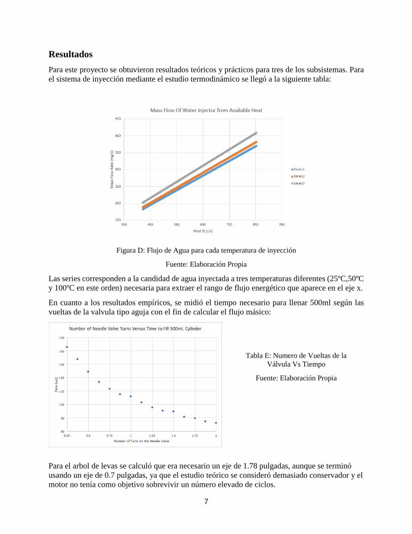
En cuanto a los resultados empíricos, se midió el tiempo necesario para llenar 500ml según las
vueltas de la valvula tipo aguja con el fin de calcular el flujo másico:
Tabla E: Numero de Vueltas de la
Válvula Vs Tiempo
Fuente: Elaboración Propia
Para el arbol de levas se calculó que era necesario un eje de 1.78 pulgadas, aunque se terminó
usando un eje de 0.7 pulgadas, ya que el estudio teórico se consideró demasiado conservador y el
motor no tenía como objetivo sobrevivir un número elevado de ciclos.
8
El piñón de distribución se diseño con un diametro necesario para reducir la velocidad a un tercio
del valor de la velocidad angular del cigüeñal, debido al incremento del número de tiempos.
También se calculó el número de dientes necesarios que resultaron ser 54.
Tras la integración del motor, no hubo tiempo para probar si se consiguió un aumento de la
eficiencia del motor, auque el motor fue capaz de arrancar durante un corto periodo de tiempo.
Conclusiones
El hecho de que los motores de seis tiempos utilicen una tecnología que aún no está arraigada en
la industria del motor fue uno de los motivos para estudiar, diseñar y fabricar su propio motor de
inyección de agua. Es cierto que miles de empresas de motores cuentan con equipos de I + D
dedicados que buscan constantemente nuevas y efectivas formas de mejorar los motores
existentes o crear otros nuevos, posible motivo por el cual no se ha desarrollado semejante
tecnología. Sin embargo, a veces el beneficio que aportan las nuevas tecnologías es incapaz de
desbancar a las tecnologías ya establecidas y que ya funcionan. Este cambio generalmente
requiere una alta inversión inicial para lograr una buena aceptación en el mercado. Sin embargo,
se ha demostrado con este proyecto que es posible crear nuevas tecnologías que mejoren la
eficiencia de los motores actuales, aunque muchas veces sean incapaces de sustituir las
tecnologías existentes por diversos motivos.

9
DESIGN AND ADAPTATION OF A FOUR-STROKE ENGINE TO A SIX
STROKE ENGINE
Author: Espejo Abela, Álvaro
Director: McGarry, Matthew
Collaborating Entity: ICAI - Universidad Pontificia de Comillas, University of San Diego.
PROJECT SUMMARY
Introduction
The next project aims at the research and development of a six-stroke engine. Given the delicate
situation of the world's energy crisis, this project targets at designing and creating an engine
capable of improving the efficiency of current four-stroke engines while conserving the previous
engine specifications. Today's engines, although they have improved their efficiency over the
years, still have a low efficiency (30-40% in most combustion and compression engines) due to
elevated thermal losses. The rest of the energy is delivered to the environment by air or water-
cooling systems, depending on the type of engine. This revolutionary idea, based on the motor
designed by Bruce Crower, works by adding two additional times using water injection. Water
has two main functions: cooling and power delivery to the engine. The water, when injected in
the fifth stroke, absorbs the heat of the cylinder and uses it to change from liquid to gaseous
state. At room temperature, water is able to expand 1600 times the volume it occupies in its
liquid state. This expansion is responsible for delivering power during the fifth stroke of the
engine. Finally, the energy that the water uses for the expansion is thermal energy that is
extracted during the last cycle or sixth cycle, the escape cycle. The purpose of this project is to
adapt an engine as easily, efficiently and economically as possible. In addition, it is about
answering the following question: Can a six-stroke engine improve the efficiency of an existing
combustion engine?
Methodology
To solve the problem, the adaptation will be divided into four main subsystems: the water injector,
the camshaft, the timing gear and the base engine. In this project, various possibilities for the
design and obtaining of the different subsystems that make up the engine will be analyzed. Before
proceeding to the final choice of each subsystem, a thermodynamic study will be made to calculate
the necessary amount of water that must be injected for the engine to operate throughout its range;
a static and fatigue mechanical study to calculate the minimum diameter necessary for the
camshaft; and a mechanical study for the camshaft timing gear profile.
After the theoretical study and taking into account the budget and other determining factors, we
will proceed with the choice of each subsystem to finally integrate them into a single engine.
Following the integration, tests will be conducted in order to find out if there has been an increase
in efficiency in the form of a reduction in fuel consumption by delivering the same power or greater
power delivery using the same fuel.
10
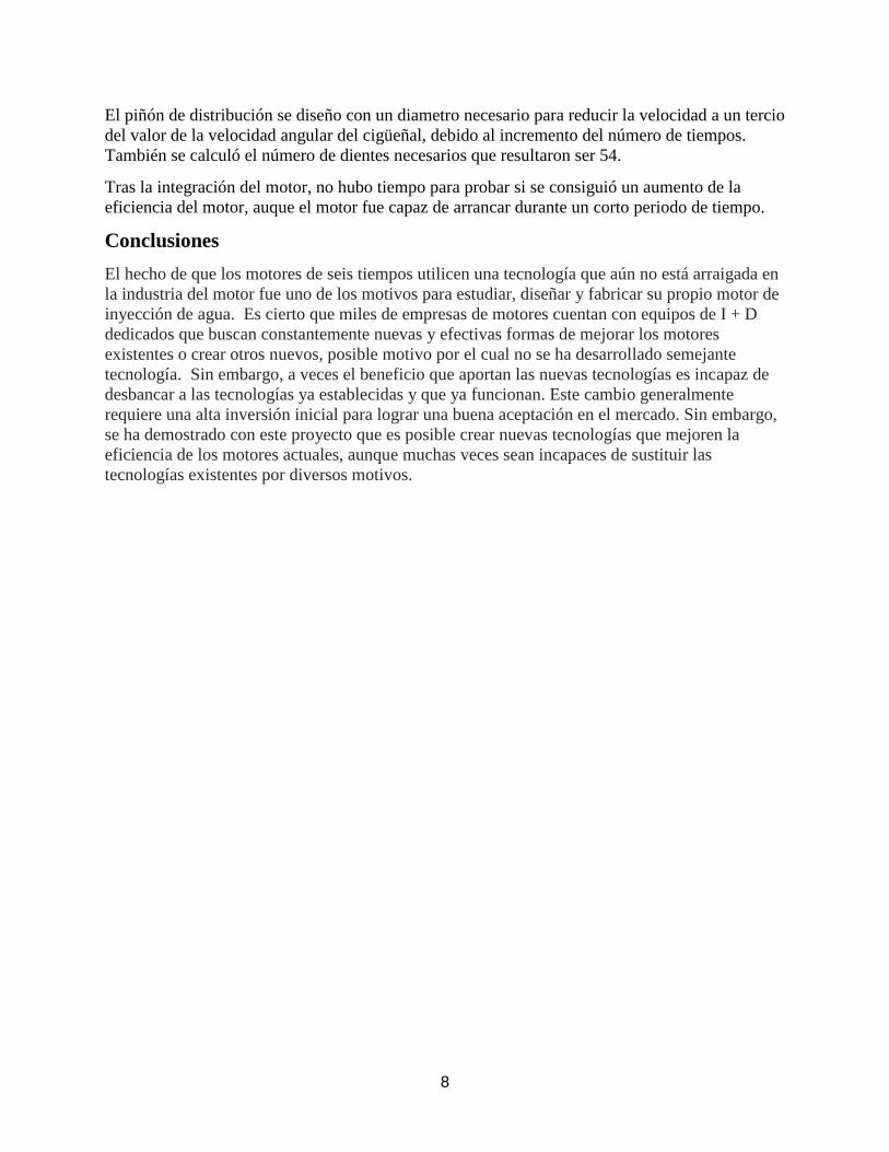
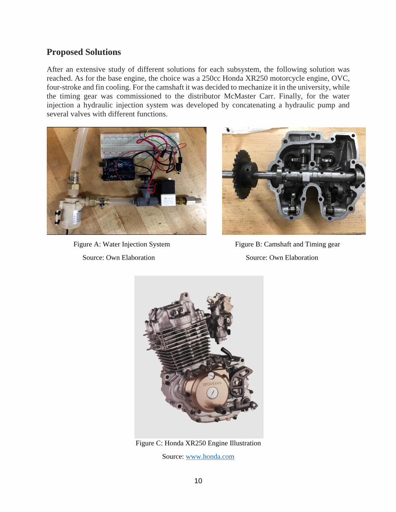
Proposed Solutions
After an extensive study of different solutions for each subsystem, the following solution was
reached. As for the base engine, the choice was a 250cc Honda XR250 motorcycle engine, OVC,
four-stroke and fin cooling. For the camshaft it was decided to mechanize it in the university, while
the timing gear was commissioned to the distributor McMaster Carr. Finally, for the water
injection a hydraulic injection system was developed by concatenating a hydraulic pump and
several valves with different functions.
Figure A: Water Injection System Figure B: Camshaft and Timing gear
Source: Own Elaboration Source: Own Elaboration
Figure C: Honda XR250 Engine Illustration
Source: www.honda.com
11
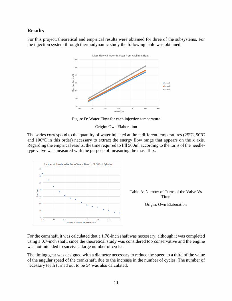
Results
For this project, theoretical and empirical results were obtained for three of the subsystems. For
the injection system through thermodynamic study the following table was obtained:
Figure D: Water Flow for each injection temperature
Origin: Own Elaboration
The series correspond to the quantity of water injected at three different temperatures (25ºC, 50ºC
and 100ºC in this order) necessary to extract the energy flow range that appears on the x axis.
Regarding the empirical results, the time required to fill 500ml according to the turns of the needle-
type valve was measured with the purpose of measuring the mass flux:
Table A: Number of Turns of the Valve Vs
Time
Origin: Own Elaboration
For the camshaft, it was calculated that a 1.78-inch shaft was necessary, although it was completed
using a 0.7-inch shaft, since the theoretical study was considered too conservative and the engine
was not intended to survive a large number of cycles.
The timing gear was designed with a diameter necessary to reduce the speed to a third of the value
of the angular speed of the crankshaft, due to the increase in the number of cycles. The number of
necessary teeth turned out to be 54 was also calculated.
12
After the integration of the engine, there was no time to test whether an increase in engine
efficiency was achieved, although the engine was able to start for a short period of time.
Conclusions
The fact that six-stroke engines use a technology that is not yet rooted in the motor industry was
one of the reasons to study, design and manufacture their own water injection engine. It is true that
thousands of engine companies have dedicated R & D teams that are constantly looking for new
and effective ways to improve existing engines or create new ones, a possible reason why such
technology has not been developed. However, sometimes the benefit provided by new
technologies is unable to unseat existing technologies that already work. This change usually
requires a high initial investment to achieve good market acceptance. However, this project has
shown that it is possible to create new technologies that improve the efficiency of current engines
at a reasonable price, although they are often unable to replace them.

13
The following project has been designed and manufactured at the University of San
Diego, California.
14
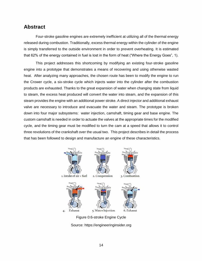
Abstract
Four-stroke gasoline engines are extremely inefficient at utilizing all of the thermal energy
released during combustion. Traditionally, excess thermal energy within the cylinder of the engine
is simply transferred to the outside environment in order to prevent overheating. It is estimated
that 62% of the energy contained in fuel is lost in the form of heat (“Where the Energy Goes”, 1).
This project addresses this shortcoming by modifying an existing four-stroke gasoline
engine into a prototype that demonstrates a means of recovering and using otherwise wasted
heat. After analyzing many approaches, the chosen route has been to modify the engine to run
the Crower cycle, a six-stroke cycle which injects water into the cylinder after the combustion
products are exhausted. Thanks to the great expansion of water when changing state from liquid
to steam, the excess heat produced will convert the water into steam, and the expansion of this
steam provides the engine with an additional power stroke. A direct injector and additional exhaust
valve are necessary to introduce and evacuate the water and steam. The prototype is broken
down into four major subsystems: water injection, camshaft, timing gear and base engine. The
custom camshaft is needed in order to actuate the valves at the appropriate times for the modified
cycle, and the timing gear must be modified to turn the cam at a speed that allows it to control
three revolutions of the crankshaft over the usual two. This project describes in detail the process
that has been followed to design and manufacture an engine of these characteristics.
Figure 0: 6-Stroke Engine Cycle
Figure 0:6-stroke Engine Cycle
Source: https://engineeringinsider.org
15
Index
Project Summary (Spanish) 5
Project Summary (English) 10
Abstract 14
Index 15
1. Context 20
1.1. Background of Need 20
1.2. Customer Need Statement 21
1.3.1. Prior Work (State of the Art) 22
2. Problem Definition 26
2.1.1. Functional Requirements 26
2.1.2. Physical Requirements 27
2.2. Assumptions 27
2.3. Constraints 27
3. Concept Development 29
3.1.2. Camshaft configuration 30
3.1.2.a. Outsourced Single Piece 30
3.1.2.b. Custom Machined Single Piece 30
3.1.2.c. Custom Machined Modular 31
3.1.3. Timing Drive 31
3.1.3.a. Fabricate 32
3.1.3.b. Salvage 32
3.1.3.c. Outsource 32
3.1.4. Water Injector Pump Types 33
3.1.4.a. Unit Injector 33
16
3.1.4.b. Unit Pump 34
3.1.4.c. Inline Pump 34
3.1.4.d. Rotary Pump 35
3.1.4.e. Water Injection System 35
3.1.5 Base Engine Selection 37
3.2. Governing Principles 38
3.3. Analysis 39
3.3.1. Mass Flow Rate for Water Injection 39
3.3.2. Gear Ratio for Timing Drive 42
3.3.3 Steam Power 48
3.4. Evaluation 54
3.5. Refinement 55
3.6. Selection 56
4. Design Specifications 57
4.1. Design Overview 57
4.1.1. Description 57
4.1.2. Design Schematics 58
4.2. Functional Specifications 58
4.3. Physical Specifications 59
4.4. Subsystems 60
5. Project Plan 68
5.1. Research 68
5.2. Construction 69
5.2.1 Camshaft Fabrication and Timing Gear Assembly 69
5.2.2 Water Injection System Assembly 75
17
5.4. Safety Assessment 80
5.5. Testing 80
5.6. Schedule 84
Table 6: Gantt Chart 84
5.7. Budget 85
6. References 89
7.1. Cam Analysis Tables 90
7.2 CAD Production Drawings 118
18
List of Figures
Figure A: Water Injection System 7
Figure B: Camshaft and Timing gear 7
Figure C: Honda XR250 Engine Illustration 7
Figure D: Water Flow for each injection temperature 8
Figure 0: 6-Stroke Engine Cycle 16
Figure 1: BMW M4 GTS water injection system illustration 24
Figure 2: Crower with his Prototype 25
Figure 3: Gerard B. Schmitz 6 Stroke Engine 27
Figure 4: Engine Functional Decomposition 31
Figure 5: Custom Modular Camshaft Schematic 33
Figure 6: Unit Pump Illustration 36
Figure 7: Inline Pump Illustration 37
Figure 8: Rotary Pump Illustration 38
Figure 9: Water Pump System Illustration 39
Figure 10: Mass Flow Rate of Water Injected at 25 ͒C vs Amount of Heat 42
Figure 11: Mass Flow Rate of Water Injected at 50 ͒C vs Amount of Heat 43
Figure 12: Mass Flow Rate of Water Injected at 100 ͒C vs Amount of Heat 43
Figure 13: Mass Flow Rate of Water Injected at all temp vs Amount of Heat 44
Figure 14: Diametral Pitch for Different Pitch Diameter Values 45
Figure 15: Camshaft Free Body Diagram 47
Figure 16: Shear Stress Function Diagram 48
Figure 17: Safety Factor vs Required AMSE Camshaft Diameter 49
Figure 18: PSI versus Horsepower for 125cc Engine 51
Figure 19: PSI versus Horsepower for 250cc Engine 52
Figure 20: PSI versus Horsepower for 500cc Engine 52
Figure 21: PSI versus Horsepower for Honda XR250 53
Figure 22: Base Engine Illustration (Honda XR 250) 53
Figure 23: Feature Schematic of Modified Engine 60
Figure 24: Process Schematic for Modified Engine 61
Figure 25: Camshaft, Valve, and Timing Gear Interconnection Diagram 64
Figure 26: Water Pump 65

19
Figure 27: Needle Valve 65
Figure 28: Solenoid Valve 65
Figure 29: Arduino Genuino Uno 66
Figure 30: Ball-check Valve 66
Figure 31: Female Yor-Lok Fitting 66
Figure 32: Stainless Steel Tube 67
Figure 33: Male Yor-Lok Fitting 67
Figure 34: Full Water Pump System Integration Photograph 72
Figure 35: Cam Analysis Rig Photograph 72
Figure 36: Cam Assembly (Left) and Stock Camshaft Photograph 75
Figure 37: Cam Assembly and Timing Gear Installed 76
Figure 38: Full Circuit Integration 78
Figure 39: Connecting Chain Between Camshaft and Driveshaft 80
Figure 40: Complete Bike Integration at University of San Diego Expo, 81
Figure 41: Number of Needle Valve Turns Vs Time to Fill 500ml Cylinder 83
Figure 42: Intake Plot 95
Figure 43: Exhaust Plot 99
Figure 44: Intake Design Plot (Initial) 105
Figure 45: Intake Design Plot (Edited) 105
Figure 46: Exhaust Design Plot (Initial) 111
Figure 47: Exhaust Design Plot (Edited) 111
Figure 48: Steam Intake Design Plot (Initial) 117
Figure 49: Steam Exhaust Design Plot (Edited) 117
List of Tables
Table A: Number of Turns of the Valve Vs Time 8
Table 1: AGMA Full-Depth Gear Tooth Specifications 46
Table 2: Honda XR 250 Specification Sheet 55
Table 3: Design Decision Matrix 57
Table 4: Mechanical Properties of AISI 1020 steel 63
Table 5: Customer Requirement Compared to Test Procedure 84
Table 6: Gantt Chart 86
Table 7: Budget for Engine Prototype 87
20
1. Context
1.1. Background of Need
Traditional internal combustion engines of any type produce significant quantities
of waste heat during their operation by nature of their design. Because all the energy
present in an engine is derived from fuel, any heat buildup within the engine, whether
from friction or combustion processes, represents fuel that has been consumed without
producing any useful work. In addition to this inherent waste, heat buildup within an
engine requires additional apparatus to remove it and keep the engine at operating
temperature, adding weight, complexity, and points of failure while increasing the amount
of back work that must be drawn from the engine’s power output.
In a world where so many machines and vehicles are powered by some form of
internal combustion engine, fuel efficiency is an extremely high priority and any method
that can increase the amount of energy extracted from fuel is worth pursuing, from both
economic and resource conservation perspectives. Since waste heat makes up such a
high percentage of the energy released from burning fuel, it is a natural area of interest
when seeking to eke out additional efficiency.
Because of the widespread use of internal combustion engines and the diversity
of applications that employ them, any attempt to harness waste heat that hopes to have
a far-reaching impact must fit the form-factor, operating characteristics, and maintenance
requirements of existing engines. If capturing waste heat means significant changes to
the way internal combustion engines are operated, used, or installed, users will likely
forgo any performance gains to avoid investing the initial effort of conversion. Similarly,
the cost of producing an engine capable of utilizing waste heat must be comparable to
current production costs; if the engine is too expensive and savings from fuel efficiency
take too long to outweigh the initial costs customers will not purchase it, and
manufacturers have no reason to produce an engine that will not sell.
In other words, this project will serve as a tool to find out the market potential of
water injection in combustion engines, without considering economic implications.
Previous revolutionary ideas have been around, but they have not unseated traditional 4
21
stroke engines, even though inventors claim to obtain an increase in efficiency. It is a
competition that looks for the balance between efficiency and cost, and 4-stroke engines
are by far not the best competitors to have.
1.2. Customer Need Statement
Automotive vehicles have been the primary means of transportation for over 50
years. It has shaped the way to our society moves and operates. In 2017, close to 79
million cars were sold worldwide (“Global Car Sales”, 1); the automotive industry is
massive. Auto Alliance estimates that the automotive industry spends close to $100 billion
a year on research and development alone (“Automotive Industry”, 1). While it is evident
that cars have become an essential building block of modern society, little development
has been put towards improving the process the engine undergoes.
Almost every modern four-stroke car or motorcycle engine suffers from three major
problems. The most prevalent of these is their inherent inefficiency. Only about 14%–30%
of the energy produced from the combustion of the fuel within the engine is used to move
it down the road. The rest of the energy created is lost via various vectors, the biggest of
which is heat exhaust. A typical car engine loses upwards of 62% of the input energy to
heat (“Where the Energy Goes”, 1). Engines produce so much heat that an additional
water or air cooling system must be implemented in order to radiate the excess and
prevent the engine from overheating and failing. Additionally, traditional four-stroke Otto
cycle engines release carbon dioxide and other greenhouse gases into the surrounding
environment. This has been a growing issue in recent years as it is linked to global
warming. Lastly, internal combustion engines run on fossil fuels, which have finite supply
and are susceptible to rapid price fluctuations. There is a need for automotive engine to
be redesigned to increase its thermal efficiency, fuel efficiency, and decrease its
emissions.
This problem is hard to solve because significant resources are continually
invested in improving and refining the current four-stroke engines, or in other forms like
electric vehicles. These last ones have recently experienced a significant growth and
expansion worldwide, as their characteristics are rapidly catching up traditional
combustion and compression engines.
22
Additionally, a lot of the subsystems within an automobile are dependent on the
current setup (heater, catalytic converter, etc.). With current methods of heat recapture
output usually comes in the form or generated electrical power, which is difficult to convey
to the wheels and has limited ancillary use.
1.3.1. Prior Work (State of the Art)
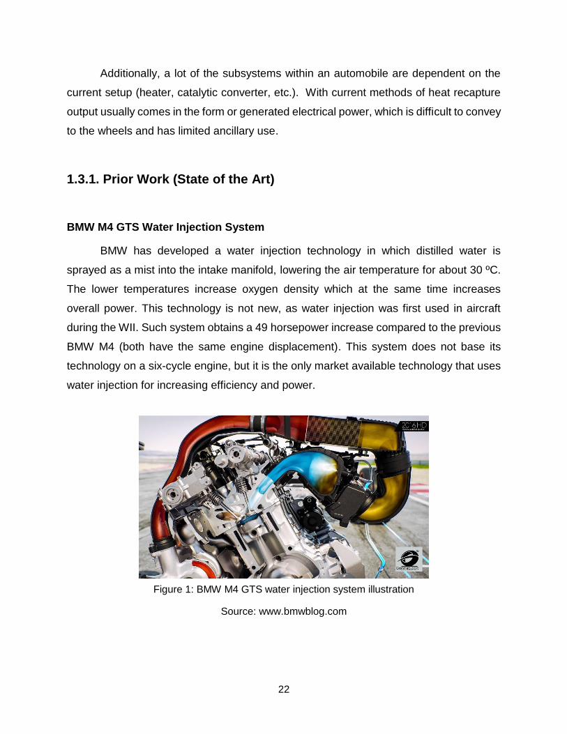
BMW M4 GTS Water Injection System
BMW has developed a water injection technology in which distilled water is
sprayed as a mist into the intake manifold, lowering the air temperature for about 30 ºC.
The lower temperatures increase oxygen density which at the same time increases
overall power. This technology is not new, as water injection was first used in aircraft
during the WII. Such system obtains a 49 horsepower increase compared to the previous
BMW M4 (both have the same engine displacement). This system does not base its
technology on a six-cycle engine, but it is the only market available technology that uses
water injection for increasing efficiency and power.
Figure 1: BMW M4 GTS water injection system illustration
Source: www.bmwblog.com
23
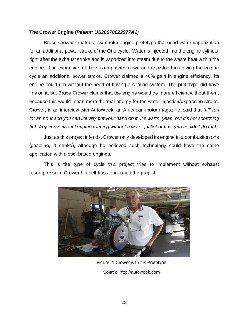
The Crower Engine (Patent: US20070022977A1)
Bruce Crower created a six-stroke engine prototype that used water vaporization
for an additional power stroke of the Otto cycle. Water is injected into the engine cylinder
right after the exhaust stroke and is vaporized into steam due to the waste heat within the
engine. The expansion of the steam pushes down on the piston thus giving the engine
cycle an additional power stroke. Crower claimed a 40% gain in engine efficiency. Its
engine could run without the need of having a cooling system. The prototype did have
fins on it, but Bruce Crower claims that the engine would be more efficient without them,
because this would mean more thermal energy for the water injection/expansion stroke.
Crower, in an interview with AutoWeek, an American motor magazine, said that “It’ll run
for an hour and you can literally put your hand on it. It’s warm, yeah, but it’s not scorching
hot. Any conventional engine running without a water jacket or fins, you couldn’t do that.”
Just as this project intends, Crower only developed its engine in a combustion one
(gasoline, 4 stroke), although he believed such technology could have the same
application with diesel-based engines.
This is the type of cycle this project tries to implement without exhaust
recompression; Crower himself has abandoned the project.
Figure 2: Crower with his Prototype
Source: http://autoweek.com
24
The Velozeta Engine (Patent: US20160032821A1)
A team of mechanical engineering students created a six-stroke engine, the
Velozeta engine. Fresh air was injected into the engine cylinder after the exhaust stroke,
which expanded due to heat and provided a second power stroke. Such engine was able
to reduce fuel consumption by 40% leading to a large air pollution reduction. Although the
power to weight ratio was smaller than that of a four-stroke engine, the Velozeta engine
achieve a major reduction in carbon monoxide pollution. This engine was developed in
2005 at the College of Engineering, Trivandrum. The group members were the following:
Mr. Boby Sebastian, Mr. U Krishnaraj, Mr. Aaron Joseph and Mr. Arun Nair George.
The Bajulaz Six-stroke Engine (Patent: US4809511A and US4513568A)
Roger Bajulaz created a six-stroke engine in 1989 that uses pre-heated air to
provide and additional expansion stroke to the Otto cycle. The engine cylinder head is
modified to have a combustion chamber and air-preheating chamber. Burning of the fuel
in the combustion chamber heats the air in the chamber surrounding it. As the air is
heated, it expands into high pressure which is then used to provide an addition power
stroke. Such engine claimed a 40% fuel consumption reduction, to be multifuel, air
pollution reduction and a comparable cost to a traditional 4 stroke engine.
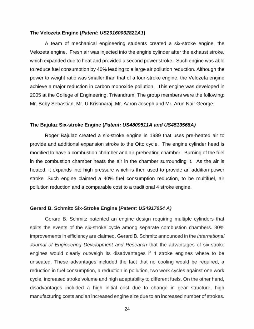
Gerard B. Schmitz Six-Stroke Engine (Patent: US4917054 A)
Gerard B. Schmitz patented an engine design requiring multiple cylinders that
splits the events of the six-stroke cycle among separate combustion chambers. 30%
improvements in efficiency are claimed. Gerard B. Schmitz announced in the International
Journal of Engineering Development and Research that the advantages of six-stroke
engines would clearly outweigh its disadvantages if 4 stroke engines where to be
unseated. These advantages included the fact that no cooling would be required, a
reduction in fuel consumption, a reduction in pollution, two work cycles against one work
cycle, increased stroke volume and high adaptability to different fuels. On the other hand,
disadvantages included a high initial cost due to change in gear structure, high
manufacturing costs and an increased engine size due to an increased number of strokes.
25
Figure 3: Gerard B. Schmitz 6 Stroke Engine
Source: http://www.ilmor.co.uk
26
2. Problem Definition
There are two problems that have to be addressed: finding a means to convert
waste heat into useful work and deciding how best to execute that solution in the
prototype.
Problem 1, Waste Heat Production:
● Traditional internal combustion engines waste as much as 62% of the fuel they
consume as waste heat.
● Existing solutions to this problem generate power from heat released by the
exhaust or radiator.
● These solutions only produce electrical energy, which is of limited use to a vehicle,
rather than adding to the engine output.
● These solutions also require the existing cooling apparatus to remain in place, and
as such only add to the complexity, weight, and cost of the system as a whole.
Problem 2, Prototype Design:
● How can waste heat be recaptured within the operation of the engine itself?
● Are there alternatives to the Crower cycle that accomplish this?
● How can the changes necessary to run such a cycle within the time and budgetary
constraints of this project be implemented?
● What other problems might be brought on as a result of those modifications?
2.1.1. Functional Requirements
1. To capture waste heat produced from a standard Otto-cycle engine by modification
the engine. (H)
2. The modified engine can have a similar power output compared to the original. (H)
3. Achieve a smaller fuel consumption than the non-modified engine.
4. Working prototype that demonstrates a 6-stroke Otto-cycle.
27
2.1.2. Physical Requirements
1. The modified engine must fit on a workshop bench.
2. The engine must have all the same material properties of a typical engine block.
3. The camshaft must be an overhead camshaft that controls each valve
independently.
4. Exhaust pipe to allow for expulsion of steam and residual water.
5. Space on top of engine block to allow for machining of water injector port.
6. A water injector must be able to connect to the timing gear.
2.2. Assumptions
The following is a list of assumptions that must be presumed for the success of
this project. The list includes assumptions about the original four stroke engine before it
is modified, as well as, basic assumptions while operating the modified engine.
1. The prototype will use a measurable source of input power.
2. It will be possible to measure the output energy of the prototype produces.
3. It will be possible to measure the heat exchange within the prototype.
4. Mixtures used within the prototype does not have any major impurities.
5. The emissions from prototype will pass EPA standards.
6. The prototype is able to be tested in basement or parking lot of Loma Hall.
7. The engine and testing system will be able to be moved around easily.
2.3. Constraints
1. Project costs must not exceed budget of $2900.
2. Project must be completed by May 11th, 2018.
3. Project design complexity must be within the capabilities of the designer.
4. Project must meet university regulations for noise and safety, as testing will be
done on campus.
28
5. Physical apparatus must be able to be transported by hand, limiting weight to
around 100lbs.
6. Physical apparatus must fit on a workshop bench, limiting footprint to around
36”x96” conservatively.
7. Components are limited to budget constraints, market availability and University of
San Diego machinery.
29
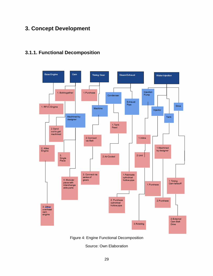
3. Concept Development
3.1.1. Functional Decomposition
Figure 4: Engine Functional Decomposition
Source: Own Elaboration
30
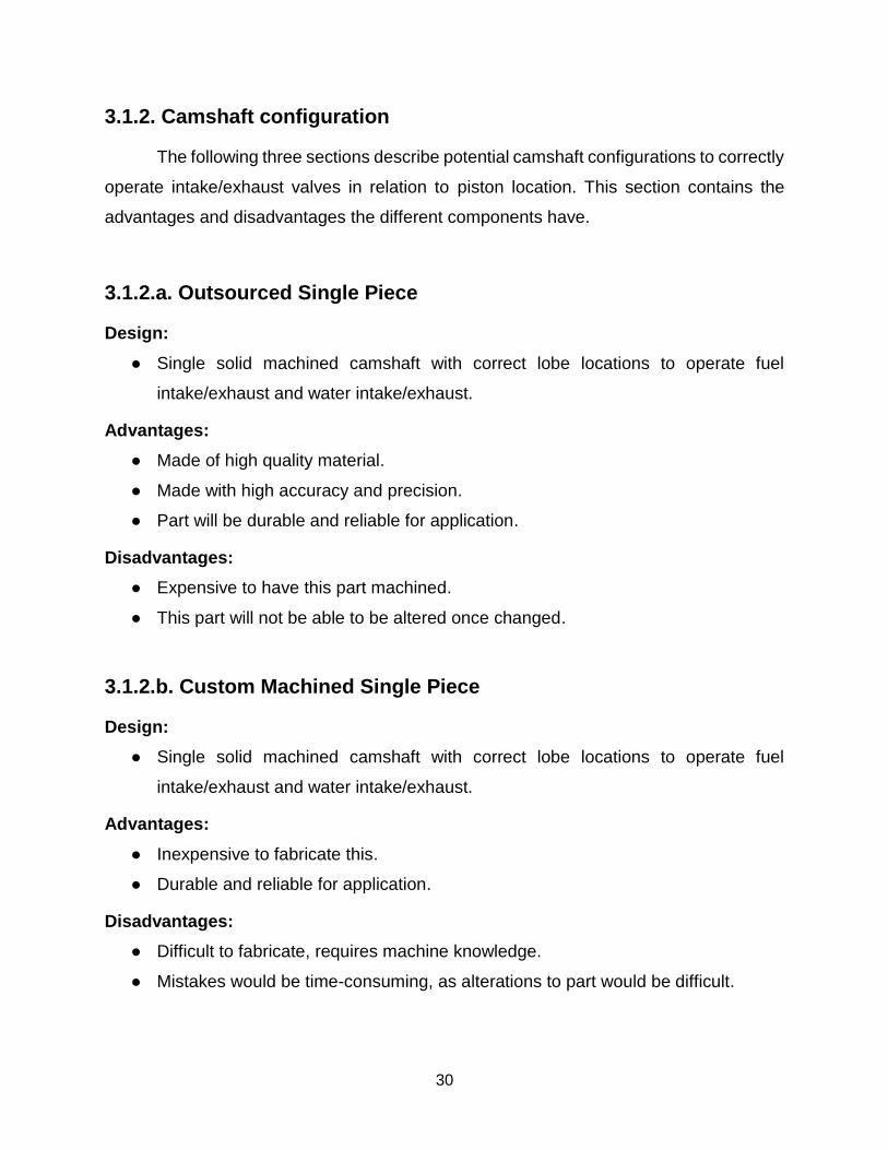
3.1.2. Camshaft configuration
The following three sections describe potential camshaft configurations to correctly
operate intake/exhaust valves in relation to piston location. This section contains the
advantages and disadvantages the different components have.
3.1.2.a. Outsourced Single Piece
Design:
● Single solid machined camshaft with correct lobe locations to operate fuel
intake/exhaust and water intake/exhaust.
Advantages:
● Made of high quality material.
● Made with high accuracy and precision.
● Part will be durable and reliable for application.
Disadvantages:
● Expensive to have this part machined.
● This part will not be able to be altered once changed.
3.1.2.b. Custom Machined Single Piece
Design:
● Single solid machined camshaft with correct lobe locations to operate fuel
intake/exhaust and water intake/exhaust.
Advantages:
● Inexpensive to fabricate this.
● Durable and reliable for application.
Disadvantages:
● Difficult to fabricate, requires machine knowledge.
● Mistakes would be time-consuming, as alterations to part would be difficult.

31
3.1.2.c. Custom Machined Modular
Design:
● Machined camshaft consisting of a base cam rod and four adjustable cam lobes
that can be locked in place at any location along the rod.
Advantages:
● Can be fabricated using CNC machine.
● Can be altered with ease to fit the need of application.
● Inexpensive to fabricate.
Disadvantages:
● Not as strong as a single piece camshaft.
● High number of fabricated parts to make assembly.
Figure 5: Custom Modular Camshaft Schematic
Source: Own Elaboration
3.1.3. Timing Drive
The following section discusses options for reducing the timing speed from ½ to ⅓
crank speed in order to allow for two additional strokes.
32
3.1.3.a. Fabricate
Design:
● Machine a unique custom gear matching the original tooth profile at 150%
diameter.
● Machined from steel.
Advantages:
● Inexpensive to manufacture.
● Gear fit can be tested and adjusted if necessary.
Disadvantages:
● Time intensive to design and machine gear with precision.
3.1.3.b. Salvage
Design:
● Scavenge for a matching set of timing gears that will provide the desired timing
speed.
Advantages:
● Inexpensive to purchase a scavenged set of timing gears.
● Large abundance of parts that can be scavenged.
Disadvantages:
● Difficulty in finding a matching pair to achieve desired timing speed.
● Difficulty in finding a gear set that will fit correctly.
● Difficulty in determining the quality of the part.
3.1.3.c. Outsource
Design:
● Commission a fabrication firm to create a custom gear matching the original tooth
profile at 150% diameter.
Advantages:
● Parts will be made with high quality material.
33
● Parts will be machined with high accuracy and precision.
● Parts will be available in a short amount of time.
Disadvantages:
● Expensive to outsource this type of machining.
● Replacements or adjustments are equally expensive.
● Still requires time investment to design part.
● Allows for a small margin of error.
3.1.4. Water Injector Pump Types
The following section discusses different pump types that can be modified to inject
precise amounts of water into the cylinder under pressure.
3.1.4.a. Unit Injector
Design:
● Combined injector and pump in single housing.
● Solenoid or cam driven.
● Mounted in injector port.
Advantages:
● Self-contained, requires no high-pressure plumbing.
● Electronic or mechanical actuation.
● Electronic or mechanical volume control.
● Inexpensive.
● Modular/individualized, install one per cylinder.
● Maintenance is relatively simple due to pump being easy to exchange.
Disadvantages:
● Takes up valuable space above the head.
● Requires dedicated local cam, or electronics.
34
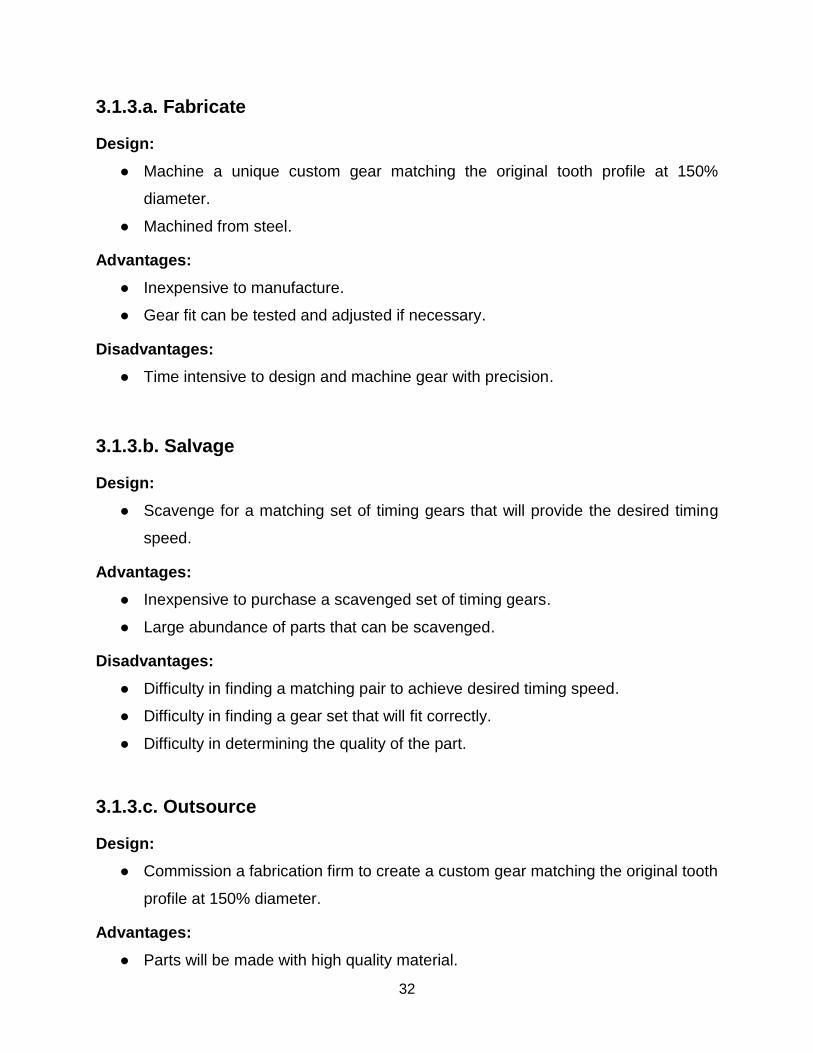
3.1.4.b. Unit Pump
Design:
● Cam driven reciprocating pump.
● High pressure line to remote injector.
● Mounted in block.
Advantages:
● Electronic or mechanical flow control.
● Inexpensive.
● Electronic or mechanical volume control.
● Modular/individualized, install one per cylinder.
Disadvantages:
● Requires dedicated cam.
● Requires high precision purpose made housing.
● Requires high pressure plumbing to injector.
Figure 6: Unit Pump Illustration
Source: www.indiamart.com
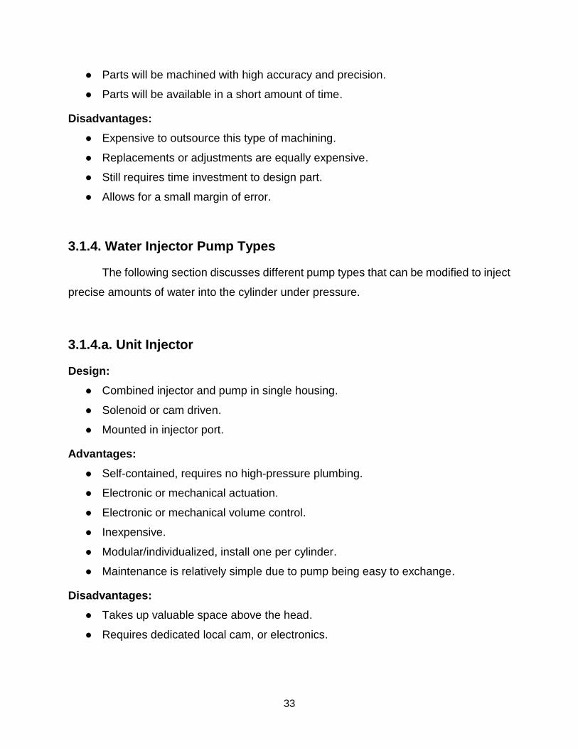
3.1.4.c. Inline Pump
Design:
● Self-contained pump, throttle, drive, timing, and governor assembly.
● Within the pump, each cylinder has a dedicated plunger running from a shared
cam and volume control.
● As the camshaft rotates, the appropriate plunger delivers fuel to its corresponding
35
injector at the precise time needed to ignite the charge.
● Pumps for all cylinders in the engine combined in one unit.
Advantages:
● Since it is self-contained the system is self-governing.
● Great for multiple cylinder engines that need to synchronize several injectors.
● Requires only belt or chain drive, cam is internal.
● Can be mounted anywhere.
Disadvantages:
● Expensive to purchase and maintain due to high tolerances.
● Many intricate pieces increase probability of failure.
● Requires high pressure plumbing to injector.
● Pump must match cylinder count or have wasted outputs and incorrect timing.
Figure 7: Inline Pump Illustration
Source: www.indiamart.com
3.1.4.d. Rotary Pump
Design:
● Radial version of inline pump.
● Multiple plungers arranged around a single cam lobe, which actuates them in order
as it rotates.
● Self-contained pump, throttle, drive, timing, and governor assembly.
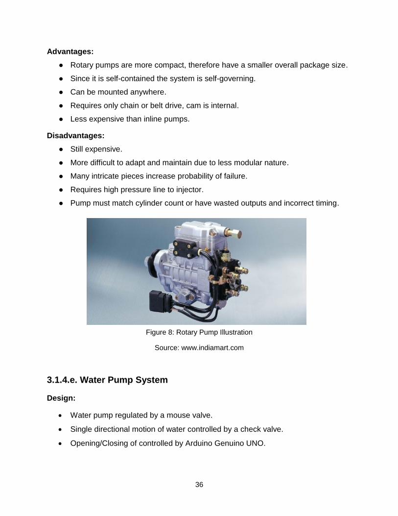
36
Advantages:
● Rotary pumps are more compact, therefore have a smaller overall package size.
● Since it is self-contained the system is self-governing.
● Can be mounted anywhere.
● Requires only chain or belt drive, cam is internal.
● Less expensive than inline pumps.
Disadvantages:
● Still expensive.
● More difficult to adapt and maintain due to less modular nature.
● Many intricate pieces increase probability of failure.
● Requires high pressure line to injector.
● Pump must match cylinder count or have wasted outputs and incorrect timing.
Figure 8: Rotary Pump Illustration
Source: www.indiamart.com
3.1.4.e. Water Pump System
Design:
• Water pump regulated by a mouse valve.
• Single directional motion of water controlled by a check valve.
• Opening/Closing of controlled by Arduino Genuino UNO.

37
Advantages
• Economical.
• Easy to control water injection rate by changing Arduino Genuino UNO code.
• Can be mounted anywhere.
Disadvantages
• Several intricate pieces increase probability of failure.
Figure 9: Water Pump System Illustration
Source: Own Elaboration
3.1.5 Base Engine Selection
There are far too many production gasoline engines that could potentially serve as
the basis for this project to list all of them here, so this section will simply describe the
attributes that would be most conducive to making the modifications required for this
project.
1. Single cylinder - aside from decreased cost compared with multiple cylinders,
using a single cylinder engine eliminates the need to coordinate the timing of cycle
events across multiple combustion chambers.
38
2. Overhead cam – due to the increased size of the timing gear, the distance
between the timing gears in a chain or belt driven overhead cam is valuable as it
eliminates the need to relocate the cam bearings.
3. Four valve - multiple exhaust valves permits the usage of stock cam profiles at
different phases since the engine must open the exhausts twice during the cycle.
4. Dedicated cam lobes - similarly, one cam lobe per valve enables programming
of two separate exhaust events into the cam without unusual geometries by simply
opening a one exhaust valve per event.
5. Air cooled - the absence of a water jacket means that boring injector ports into
the head will not cause coolant leaks.
6. Wasted spark - a spark event every revolution of the crank means that the ignition
timing does not need be altered to compensate for the extra revolution per cycle.
3.2. Governing Principles
Below are the areas of engineering that this project involves:
● Fluid Dynamics (Pumping and Water Injection)
● Thermodynamics (Otto-cycle and Water: Liquid to Vapor)
● Heat Transfer (Waste Heat Transfer to Injected Water)
● Solid Mechanics / FEA (Stress and Strain on Machined Components)
● Material Science (Material Selection)
● Manufacturability (Machining)
● Kinematics (Timing Gears, Camshaft, and Water Injection)
● Design of Machine Elements (Fatigue Failure for Machined Components)
● Tribology (Bearings, Lubrication, and Wear on Machined Components)
39
3.3. Analysis
3.3.1. Mass Flow Rate for Water Injection
The following analysis demonstrates the relationship between the amount of waste
heat available in the engine and the amount of water that can be converted into vapor.
To perform the analysis a few assumptions need to be made about the system:
● The amount of heat available to be used from combustion is at most 33% of the
total heat.
● The analysis will be performed on the assumption that the injected water
temperature is 25, 50, and 100 degrees Celsius.
● The mass flow rate of fuel from the fuel injector is approximately 5.5 mg/min.
The total amount of heat released from combustion is about 47 MJ/kg; approximately
66% of this heat is lost and approximately 33% of that heat is lost to engine cooling. This
is the theoretical maximum amount of heat the cylinder have to convert water into steam
𝑄𝑖𝑛 = (0.66)(47) = 31.02(0.3) = 9.306 MJ/kg = 9306 kJ/kg
𝑚. = 5.5 𝑚𝑔
𝑚𝑖𝑛= 0.0917
𝑚𝑔
𝑠
𝑄𝑖𝑛. = 𝑚.(𝑄𝑖𝑛) = (0.0917
𝑚𝑔
𝑠)(9306
𝑘𝐽
𝑠) = 853.4J/s
From the saturated water table, the internal energy of water is as follows:
● At 25 ͒C: 𝑢𝑓 = 104.83kJ/kg and 𝑢𝑔 = 2409.1kJ/kg
● At 50 ͒C: 𝑢𝑓 = 209.47kJ/kg and 𝑢𝑔 = 2443.0kJ/kg
● At 100 C͒: 𝑢𝑓 = 419.39kJ/kg and 𝑢𝑔 = 2506.0kJ/kg
Now looking at the water injection, to determine the correct mass flow rate for water
the following equation is used:
𝑄𝑖𝑛. = 𝑚.(𝑢𝑔 − 𝑢𝑓) ⇒ 𝑚. =
𝑄𝑖𝑛.
(𝑢𝑔 − 𝑢𝑓)
40
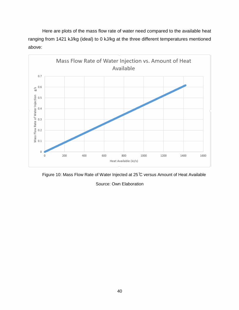
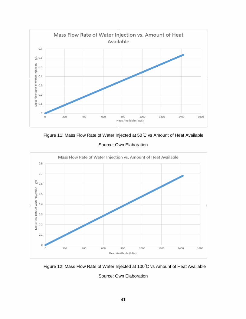
Here are plots of the mass flow rate of water need compared to the available heat
ranging from 1421 kJ/kg (ideal) to 0 kJ/kg at the three different temperatures mentioned
above:
Figure 10: Mass Flow Rate of Water Injected at 25 C͒ versus Amount of Heat Available
Source: Own Elaboration
41
Figure 11: Mass Flow Rate of Water Injected at 50 C͒ vs Amount of Heat Available
Source: Own Elaboration
Figure 12: Mass Flow Rate of Water Injected at 100 C͒ vs Amount of Heat Available
Source: Own Elaboration
42
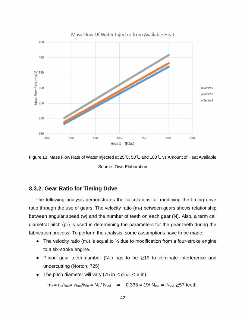
Figure 13: Mass Flow Rate of Water Injected at 25 C͒, 50 C͒ and 100 C͒ vs Amount of Heat Available
Source: Own Elaboration
3.3.2. Gear Ratio for Timing Drive
The following analysis demonstrates the calculations for modifying the timing drive
ratio through the use of gears. The velocity ratio (mv) between gears shows relationship
between angular speed (w) and the number of teeth on each gear (N). Also, a term call
diametral pitch (pd) is used in determining the parameters for the gear teeth during the
fabrication process. To perform the analysis, some assumptions have to be made:
● The velocity ratio (mv) is equal to ⅓ due to modification from a four-stroke engine
to a six-stroke engine.
● Pinion gear teeth number (Nin) has to be ≥19 to eliminate interference and
undercutting (Norton, 725).
● The pitch diameter will vary (75 in ≤ dpitch ≤ 3 in).
mv = rin/rout= wout/win = Nin/ Nout ⇒ 0.333 = 19/ Nout ⇒ Nout ≥57 teeth.
(KJ/s)
43
The number comes out to be exactly 57 teeth if the modulus of the gears are kept the
same. Increasing the number of teeth would mean that the diametral pitch should be
increased or the modulus would have to be changed. Increasing the diametral pitch would
affect the output speed while changing the modulus would break the gearing condition.
The final decision was to externally mount the timing gear, which meant that a new
crankshaft gear had to be obtained.
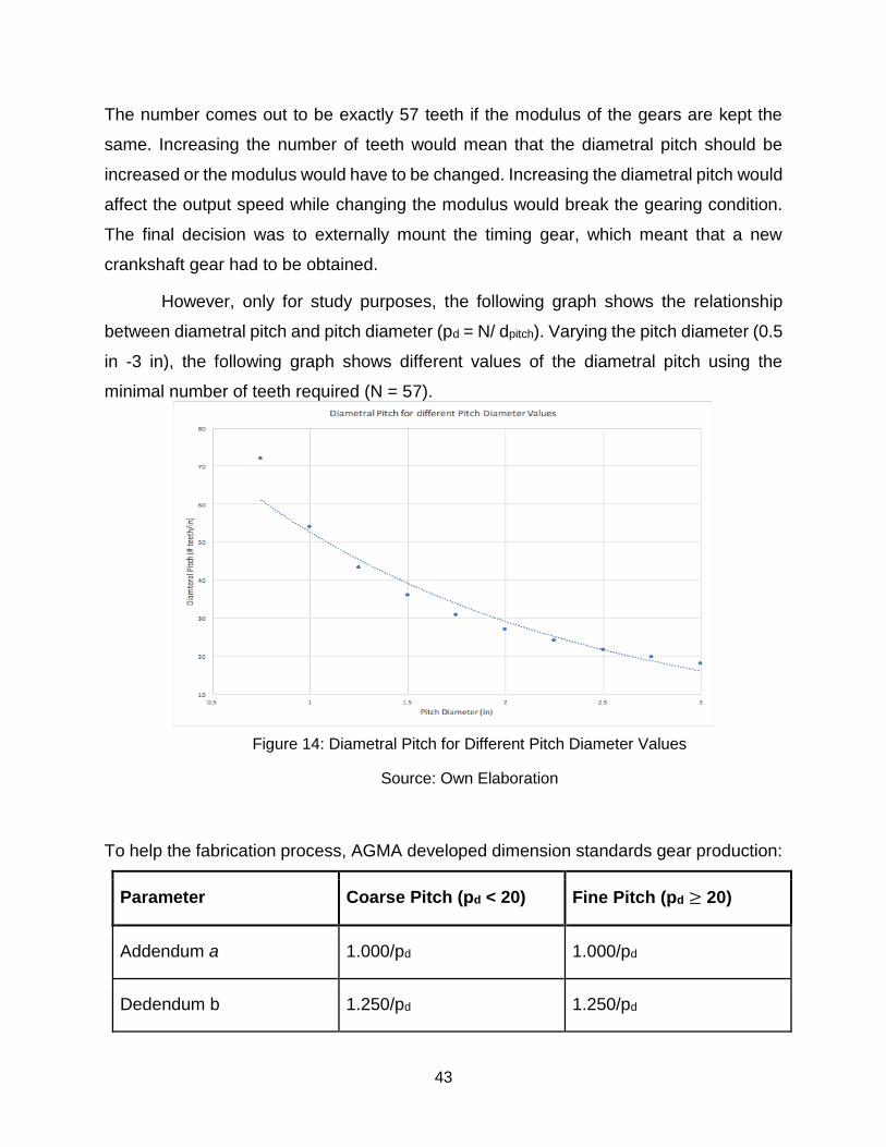
However, only for study purposes, the following graph shows the relationship
between diametral pitch and pitch diameter (pd = N/ dpitch). Varying the pitch diameter (0.5
in -3 in), the following graph shows different values of the diametral pitch using the
minimal number of teeth required (N = 57).
Figure 14: Diametral Pitch for Different Pitch Diameter Values
Source: Own Elaboration
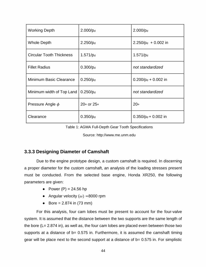
To help the fabrication process, AGMA developed dimension standards gear production:
Parameter Coarse Pitch (pd < 20) Fine Pitch (pd ≥ 20)
Addendum a 1.000/pd 1.000/pd
Dedendum b 1.250/pd 1.250/pd
44
Working Depth 2.000/pd 2.000/pd
Whole Depth 2.250/pd 2.250/pd + 0.002 in
Circular Tooth Thickness 1.571/pd 1.571/pd
Fillet Radius 0.300/pd not standardized
Minimum Basic Clearance 0.250/pd 0.200/pd + 0.002 in
Minimum width of Top Land 0.250/pd not standardized
Pressure Angle 𝜙 20∘ or 25∘ 20∘
Clearance 0.350/pd 0.350/pd + 0.002 in
Table 1: AGMA Full-Depth Gear Tooth Specifications
Source: http://www.me.unm.edu
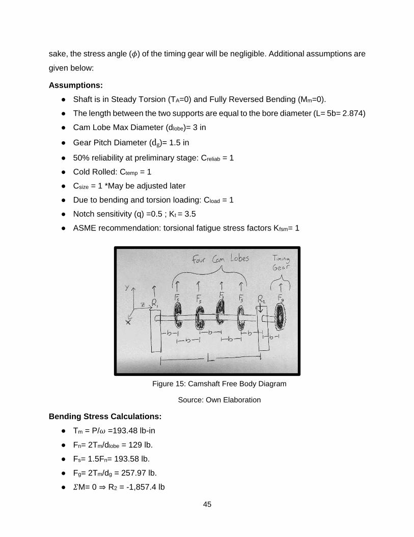
3.3.3 Designing Diameter of Camshaft
Due to the engine prototype design, a custom camshaft is required. In discerning
a proper diameter for the custom camshaft, an analysis of the loading stresses present
must be conducted. From the selected base engine, Honda XR250, the following
parameters are given:
● Power (P) = 24.56 hp
● Angular velocity (𝜔) =8000 rpm
● Bore = 2.874 in (73 mm)
For this analysis, four cam lobes must be present to account for the four-valve
system. It is assumed that the distance between the two supports are the same length of
the bore (L= 2.874 in), as well as, the four cam lobes are placed even between those two
supports at a distance of b= 0.575 in. Furthermore, it is assumed the camshaft timing
gear will be place next to the second support at a distance of b= 0.575 in. For simplistic
45
sake, the stress angle (𝜙) of the timing gear will be negligible. Additional assumptions are
given below:
Assumptions:
● Shaft is in Steady Torsion (TA=0) and Fully Reversed Bending (Mm=0).
● The length between the two supports are equal to the bore diameter (L= 5b= 2.874)
● Cam Lobe Max Diameter (dlobe)= 3 in
● Gear Pitch Diameter (dg)= 1.5 in
● 50% reliability at preliminary stage: Creliab = 1
● Cold Rolled: Ctemp = 1
● Csize = 1 *May be adjusted later
● Due to bending and torsion loading: Cload = 1
● Notch sensitivity (q) =0.5 ; Kt = 3.5
● ASME recommendation: torsional fatigue stress factors Kfsm= 1
Figure 15: Camshaft Free Body Diagram
Source: Own Elaboration
Bending Stress Calculations:
● Tm = P/𝜔 =193.48 lb-in
● Fn= 2Tm/dlobe = 129 lb.
● Fs= 1.5Fn= 193.58 lb.
● Fg= 2Tm/dg = 257.97 lb.
● 𝛴M= 0 ⇒ R2 = -1,857.4 lb
46
● 𝛴Fy= 0 ⇒ R1 = 825.51 lb
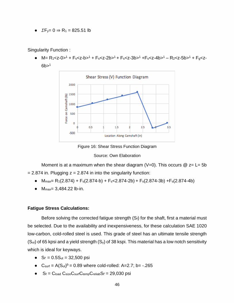
Singularity Function :
● M= R1<z-0>1 + Fs<z-b>1 + Fs<z-2b>1 + Fs<z-3b>1 +Fs<z-4b>1 – R2<z-5b>1 + Fg<z-
6b>1
Figure 16: Shear Stress Function Diagram
Source: Own Elaboration
Moment is at a maximum when the shear diagram (V=0). This occurs @ z= L= 5b
= 2.874 in. Plugging z = 2.874 in into the singularity function:
● Mmax= R1(2.874) + Fs(2.874-b) + Fs<2.874-2b) + Fs(2.874-3b) +Fs(2.874-4b)
● Mmax= 3,484.22 lb-in.
Fatigue Stress Calculations:
Before solving the corrected fatigue strength (Sf) for the shaft, first a material must
be selected. Due to the availability and inexpensiveness, for these calculation SAE 1020
low-carbon, cold-rolled steel is used. This grade of steel has an ultimate tensile strength
(Sut) of 65 kpsi and a yield strength (Sy) of 38 kspi. This material has a low notch sensitivity
which is ideal for keyways.
● Sf’ = 0.5Sut = 32,500 psi
● Csurf = A(Sut)b = 0.89 where cold-rolled: A=2.7; b= -.265
● Sf = Cload CsizeCsurfCtempCreliabSf’ = 29,030 psi
47
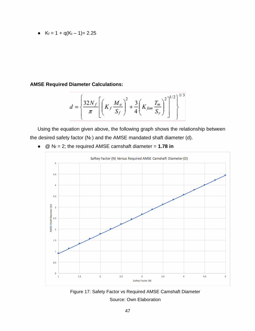
● Kf = 1 + q(Kt – 1)= 2.25
AMSE Required Diameter Calculations:
Using the equation given above, the following graph shows the relationship between
the desired safety factor (Nf ) and the AMSE mandated shaft diameter (d).
● @ Nf = 2; the required AMSE camshaft diameter = 1.78 in
Figure 17: Safety Factor vs Required AMSE Camshaft Diameter
Source: Own Elaboration
48
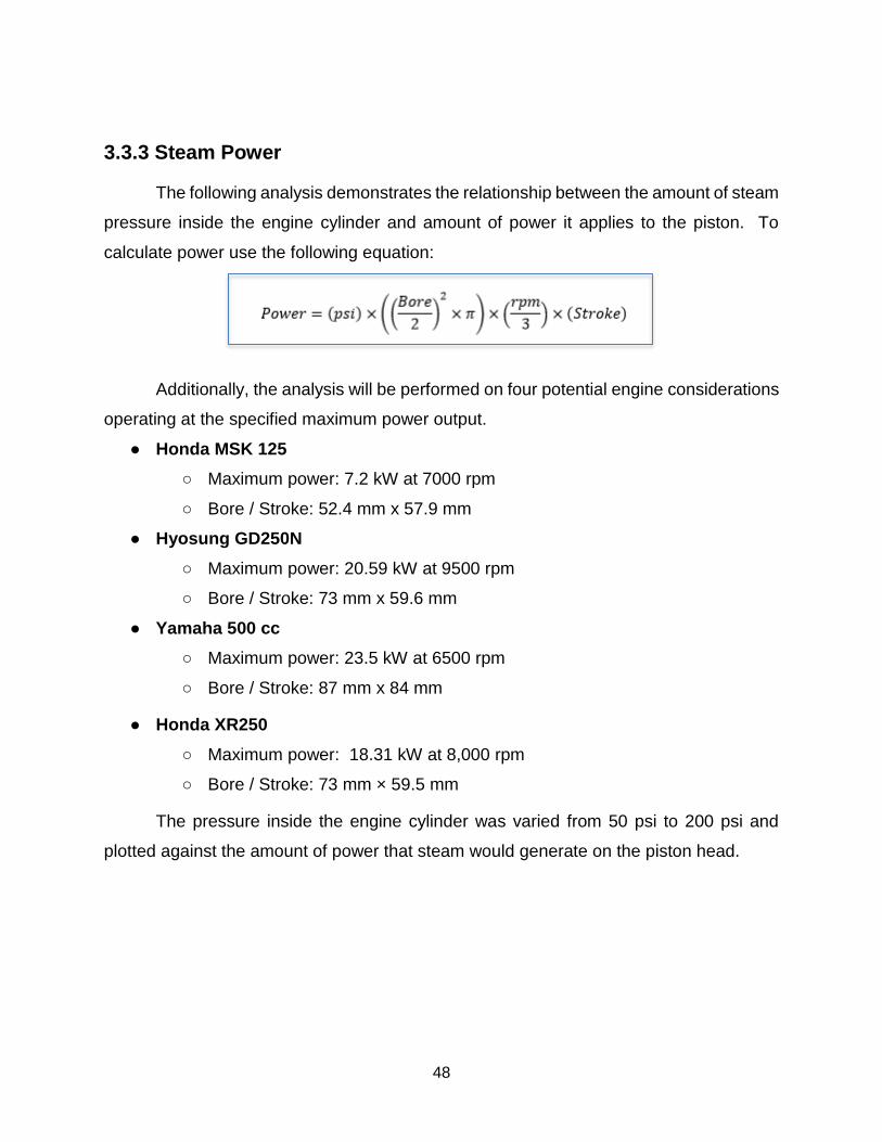
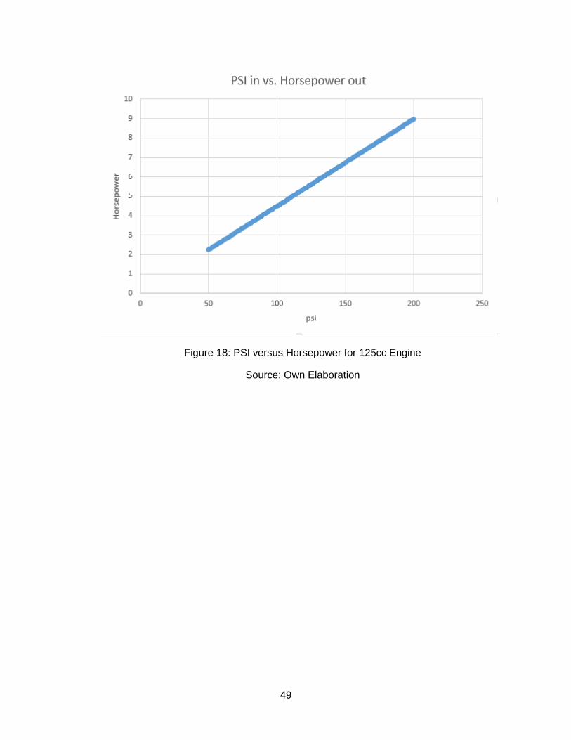
3.3.3 Steam Power
The following analysis demonstrates the relationship between the amount of steam
pressure inside the engine cylinder and amount of power it applies to the piston. To
calculate power use the following equation:
Additionally, the analysis will be performed on four potential engine considerations
operating at the specified maximum power output.
● Honda MSK 125
○ Maximum power: 7.2 kW at 7000 rpm
○ Bore / Stroke: 52.4 mm x 57.9 mm
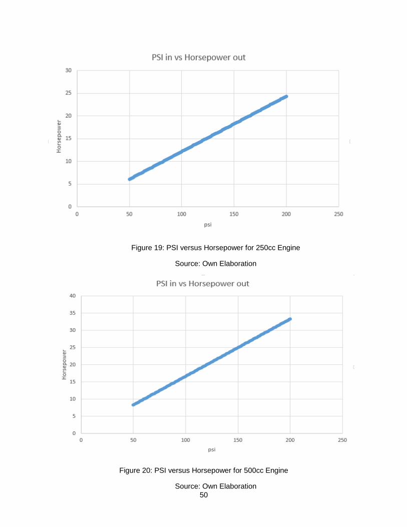
● Hyosung GD250N
○ Maximum power: 20.59 kW at 9500 rpm
○ Bore / Stroke: 73 mm x 59.6 mm
● Yamaha 500 cc
○ Maximum power: 23.5 kW at 6500 rpm
○ Bore / Stroke: 87 mm x 84 mm
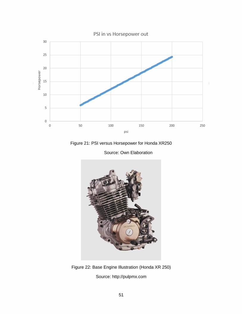
● Honda XR250
○ Maximum power: 18.31 kW at 8,000 rpm
○ Bore / Stroke: 73 mm × 59.5 mm
The pressure inside the engine cylinder was varied from 50 psi to 200 psi and
plotted against the amount of power that steam would generate on the piston head.
49
Figure 18: PSI versus Horsepower for 125cc Engine
Source: Own Elaboration
50
Figure 19: PSI versus Horsepower for 250cc Engine
Source: Own Elaboration
Figure 20: PSI versus Horsepower for 500cc Engine
Source: Own Elaboration
51
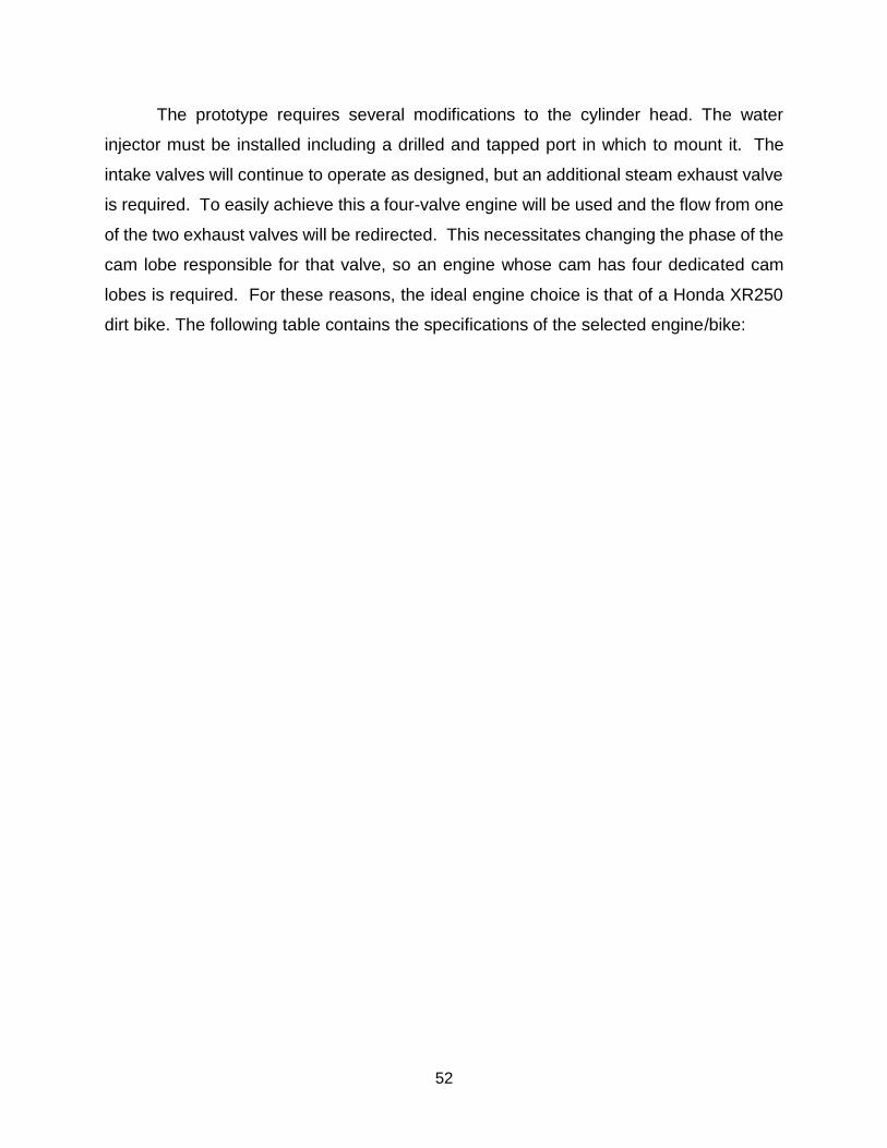
Figure 21: PSI versus Horsepower for Honda XR250
Source: Own Elaboration
Figure 22: Base Engine Illustration (Honda XR 250)
Source: http://pulpmx.com
52
The prototype requires several modifications to the cylinder head. The water
injector must be installed including a drilled and tapped port in which to mount it. The
intake valves will continue to operate as designed, but an additional steam exhaust valve
is required. To easily achieve this a four-valve engine will be used and the flow from one
of the two exhaust valves will be redirected. This necessitates changing the phase of the
cam lobe responsible for that valve, so an engine whose cam has four dedicated cam
lobes is required. For these reasons, the ideal engine choice is that of a Honda XR250
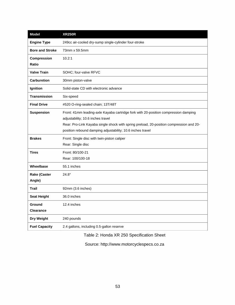
dirt bike. The following table contains the specifications of the selected engine/bike:
53
Table 2: Honda XR 250 Specification Sheet
Source: http://www.motorcyclespecs.co.za
Model XR250R
Engine Type 249cc air-cooled dry-sump single-cylinder four-stroke
Bore and Stroke 73mm x 59.5mm
Compression
Ratio
10.2:1
Valve Train SOHC; four-valve RFVC
Carburetion 30mm piston-valve
Ignition Solid-state CD with electronic advance
Transmission Six-speed
Final Drive #520 O-ring-sealed chain; 13T/48T
Suspension Front: 41mm leading-axle Kayaba cartridge fork with 20-position compression damping
adjustability; 10.6 inches travel
Rear: Pro-Link Kayaba single shock with spring preload, 20-position compression and 20-
position rebound damping adjustability; 10.6 inches travel
Brakes Front: Single disc with twin-piston caliper
Rear: Single disc
Tires Front: 80/100-21
Rear: 100/100-18
Wheelbase 55.1 inches
Rake (Caster
Angle)
24.8°
Trail 92mm (3.6 inches)
Seat Height 36.0 inches
Ground
Clearance
12.4 inches
Dry Weight 240 pounds
Fuel Capacity 2.4 gallons, including 0.5-gallon reserve
54
Since the engine will be modified to operate from four to six strokes, the timing
gear connected to the camshaft must produce the appropriate reduction in speed. This
engine will require an overhead camshaft configuration to allow space for the modified
timing gear, since it must be 50% larger than the original. The timing gears located on the
camshaft and crankshaft will be connected via an external drive chain.
3.4. Evaluation
For the cam, cost likely prohibits outsourcing production, leaving either a single-
piece or modular cam fabricated in-house. The modular cam has a significant advantage
here, since it is not only easier to machine, but also easier to adjust and modify. The
capability to CNC complex curves like those found on the cam lobes is invaluable as well,
which combined with the other advantages offsets the decreased strength.
For the timing gear, outsourcing is implies a higher cost. While finding a
mismatched set of gears that produce the correct reduction is possible and the least
expensive option, it is unlikely and would require significant time to search, as well as
replacement of the crank end gear which may be difficult or impossible depending on the
engine. This leaves machining a gear, which is still inexpensive, allows the crank gear to
be retained, and allows a higher degree of customization. However, due to time
constraints, the final decision was to outsource the timing gear, as a suitable gear for a
reasonable price within the budget was found.
For the injection system, an inline or rotary pump would be ideal; either of these
would make installation much easier since all they require is a drive belt from the engine
crank, and can be mounted externally, so if the budget was not a concern it is a very good
choice. Wasted outputs are of no consequence for a demonstration of concept, and if
applied to a single cylinder engine the timing issues are irrelevant. Unit pumps or injectors
could be made to work, but there may not be room in the head for a unit injector drive,
and the lack of an electrical engineer on the team means electronically driven versions
may be too difficult to work with.
In the first semester, a diesel pump was used. Although it initially worked (it was
able to spray/inject the required mass flow), water is non-lubricant. The pump was
55
designed for diesel intake which acts as a lubricant and enables correct proper operation
of the subsystem. The pump eventually rusted and became unusable. After this system
failure, the developing of the water pump injection system described before was
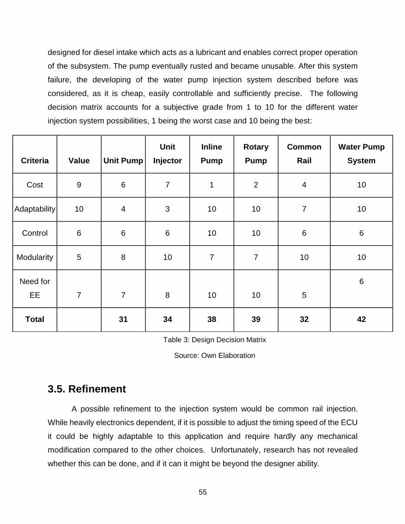
considered, as it is cheap, easily controllable and sufficiently precise. The following
decision matrix accounts for a subjective grade from 1 to 10 for the different water
injection system possibilities, 1 being the worst case and 10 being the best:
Table 3: Design Decision Matrix
Source: Own Elaboration
3.5. Refinement
A possible refinement to the injection system would be common rail injection.
While heavily electronics dependent, if it is possible to adjust the timing speed of the ECU
it could be highly adaptable to this application and require hardly any mechanical
modification compared to the other choices. Unfortunately, research has not revealed
whether this can be done, and if it can it might be beyond the designer ability.
Criteria Value Unit Pump
Unit
Injector
Inline
Pump
Rotary
Pump
Common
Rail
Water Pump
System
Cost 9 6 7 1 2 4 10
Adaptability 10 4 3 10 10 7 10
Control 6 6 6 10 10 6 6
Modularity 5 8 10 7 7 10 10
Need for
EE 7 7 8 10 10 5
6
Total 31 34 38 39 32 42
56
3.6. Selection
For the above reasons, it makes the most sense to self-machine the parts for the
cam; the modular cam in particular has numerous advantages that make it a clear choice.
The final decision was to outsource the timing gear due to time constraints. As for the
water injection, the wining system was the water pump injection system described in
3.1.4.e.

57
4. Design Specifications
4.1. Design Overview
4.1.1. Description
The prototype requires several modifications to the cylinder head. A direct injector
must be installed including a drilled and tapped port in which to mount it. The intake
valves will continue to operate as designed, but an additional steam exhaust valve is
required. To easily achieve this, a four-valve engine will be used and the flow from one
of the two exhaust valves will be redirected. This necessitates changing the phase of the
cam lobe responsible for that valve, so an engine whose cam has four dedicated cam
lobes is required.
Since the engine will be modified to operate from four to six strokes, the timing
gear connected to the camshaft must produce the appropriate reduction in speed. The
engine will require an overhead camshaft configuration to allow space for the modified
timing gear, since it must be 50% larger than the original. The timing gears located on the
camshaft and crankshaft will be connected via the original drive chain.
58
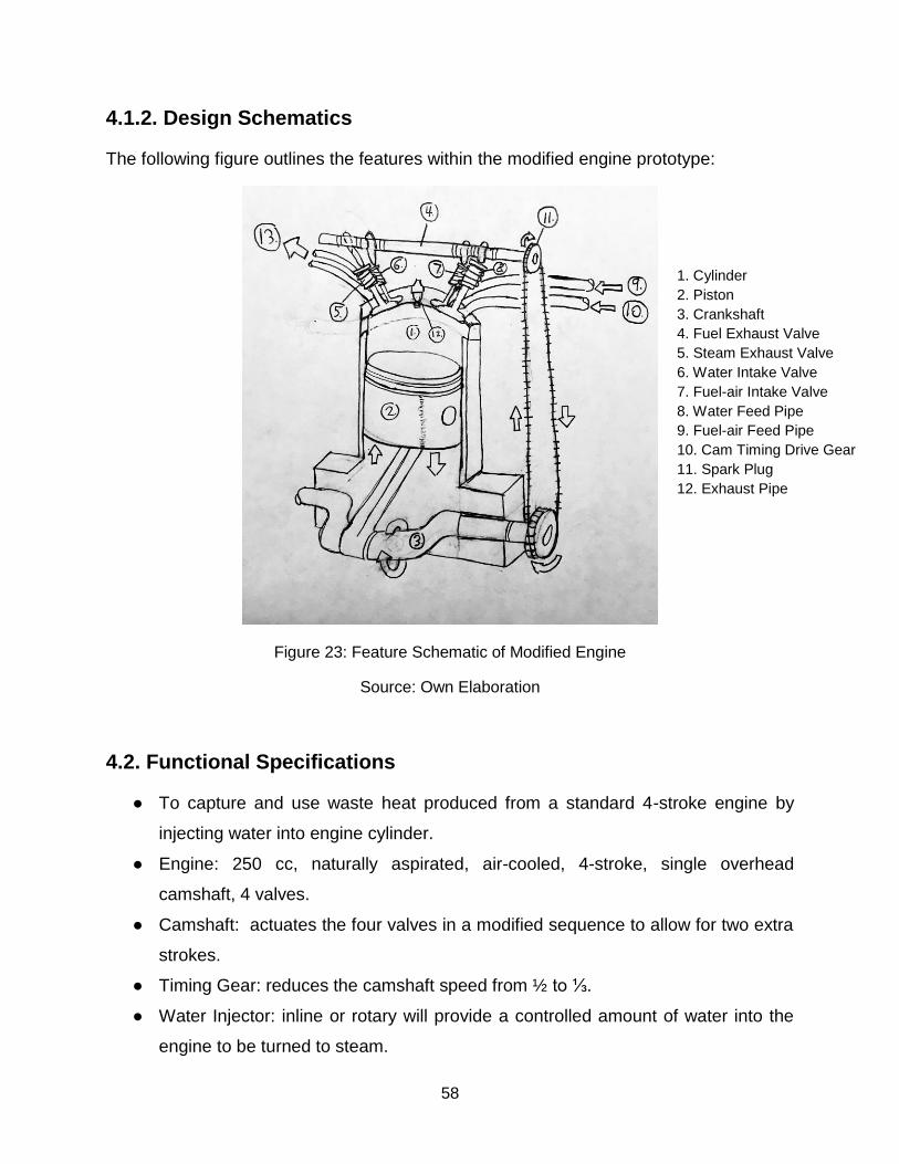
4.1.2. Design Schematics
The following figure outlines the features within the modified engine prototype:
Figure 23: Feature Schematic of Modified Engine
Source: Own Elaboration
4.2. Functional Specifications
● To capture and use waste heat produced from a standard 4-stroke engine by
injecting water into engine cylinder.
● Engine: 250 cc, naturally aspirated, air-cooled, 4-stroke, single overhead
camshaft, 4 valves.
● Camshaft: actuates the four valves in a modified sequence to allow for two extra
strokes.
● Timing Gear: reduces the camshaft speed from ½ to ⅓.
● Water Injector: inline or rotary will provide a controlled amount of water into the
engine to be turned to steam.
1. Cylinder 2. Piston 3. Crankshaft 4. Fuel Exhaust Valve 5. Steam Exhaust Valve 6. Water Intake Valve 7. Fuel-air Intake Valve 8. Water Feed Pipe 9. Fuel-air Feed Pipe 10. Cam Timing Drive Gear 11. Spark Plug 12. Exhaust Pipe

59
The following diagram describes the stages of the 6 stroke cycle:
Figure 24: Process Schematic for Modified Engine
Source: Own Elaboration
4.3. Physical Specifications
● Components must fit on a workshop bench, approximately 36in x 96in.
● Modification parts shall have the same material properties of a typical engine block
● Weight (engine): 75 lbs.
● Weight (total): 100 lbs.
Air/Fuel Intake Stroke
Steam Exhaust Stroke
Power Stroke Compression Stroke
Exhaust Stroke Steam Power Stroke
Fuel is ignited
Water is Injected and Flashes to Steam
60
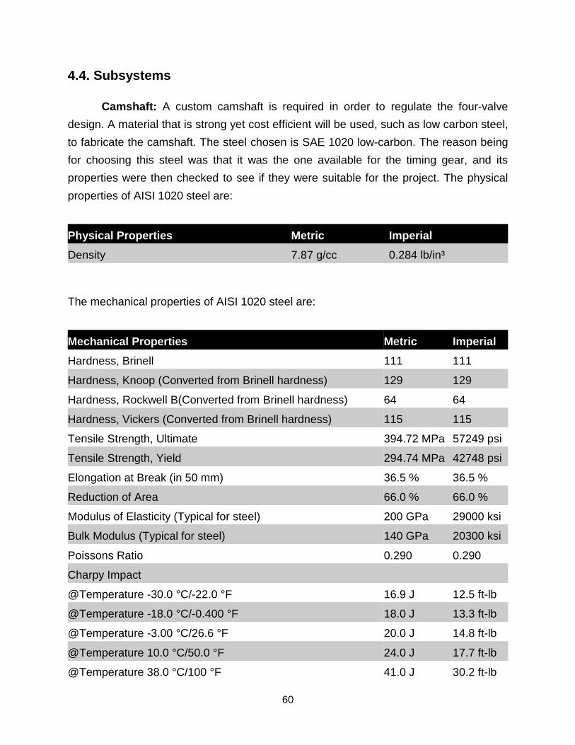
4.4. Subsystems
Camshaft: A custom camshaft is required in order to regulate the four-valve
design. A material that is strong yet cost efficient will be used, such as low carbon steel,
to fabricate the camshaft. The steel chosen is SAE 1020 low-carbon. The reason being
for choosing this steel was that it was the one available for the timing gear, and its
properties were then checked to see if they were suitable for the project. The physical
properties of AISI 1020 steel are:
Physical Properties Metric Imperial
Density 7.87 g/cc 0.284 lb/in³
The mechanical properties of AISI 1020 steel are:
Mechanical Properties Metric Imperial
Hardness, Brinell 111 111
Hardness, Knoop (Converted from Brinell hardness) 129 129
Hardness, Rockwell B(Converted from Brinell hardness) 64 64
Hardness, Vickers (Converted from Brinell hardness) 115 115
Tensile Strength, Ultimate 394.72 MPa 57249 psi
Tensile Strength, Yield 294.74 MPa 42748 psi
Elongation at Break (in 50 mm) 36.5 % 36.5 %
Reduction of Area 66.0 % 66.0 %
Modulus of Elasticity (Typical for steel) 200 GPa 29000 ksi
Bulk Modulus (Typical for steel) 140 GPa 20300 ksi
Poissons Ratio 0.290 0.290
Charpy Impact
@Temperature -30.0 °C/-22.0 °F 16.9 J 12.5 ft-lb
@Temperature -18.0 °C/-0.400 °F 18.0 J 13.3 ft-lb
@Temperature -3.00 °C/26.6 °F 20.0 J 14.8 ft-lb
@Temperature 10.0 °C/50.0 °F 24.0 J 17.7 ft-lb
@Temperature 38.0 °C/100 °F 41.0 J 30.2 ft-lb
61
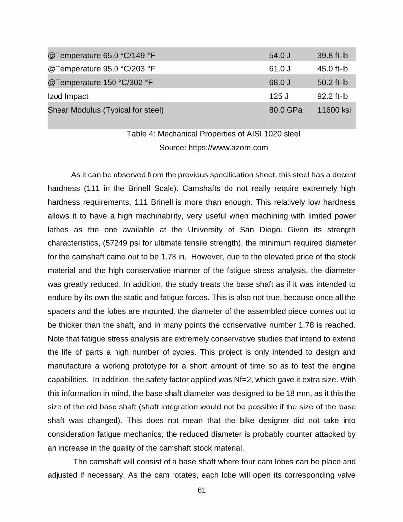
@Temperature 65.0 °C/149 °F 54.0 J 39.8 ft-lb
@Temperature 95.0 °C/203 °F 61.0 J 45.0 ft-lb
@Temperature 150 °C/302 °F 68.0 J 50.2 ft-lb
Izod Impact 125 J 92.2 ft-lb
Shear Modulus (Typical for steel) 80.0 GPa 11600 ksi
Table 4: Mechanical Properties of AISI 1020 steel
Source: https://www.azom.com
As it can be observed from the previous specification sheet, this steel has a decent
hardness (111 in the Brinell Scale). Camshafts do not really require extremely high
hardness requirements, 111 Brinell is more than enough. This relatively low hardness
allows it to have a high machinability, very useful when machining with limited power
lathes as the one available at the University of San Diego. Given its strength
characteristics, (57249 psi for ultimate tensile strength), the minimum required diameter
for the camshaft came out to be 1.78 in. However, due to the elevated price of the stock
material and the high conservative manner of the fatigue stress analysis, the diameter
was greatly reduced. In addition, the study treats the base shaft as if it was intended to
endure by its own the static and fatigue forces. This is also not true, because once all the
spacers and the lobes are mounted, the diameter of the assembled piece comes out to
be thicker than the shaft, and in many points the conservative number 1.78 is reached.
Note that fatigue stress analysis are extremely conservative studies that intend to extend
the life of parts a high number of cycles. This project is only intended to design and
manufacture a working prototype for a short amount of time so as to test the engine
capabilities. In addition, the safety factor applied was Nf=2, which gave it extra size. With
this information in mind, the base shaft diameter was designed to be 18 mm, as it this the
size of the old base shaft (shaft integration would not be possible if the size of the base
shaft was changed). This does not mean that the bike designer did not take into
consideration fatigue mechanics, the reduced diameter is probably counter attacked by
an increase in the quality of the camshaft stock material.
The camshaft will consist of a base shaft where four cam lobes can be place and
adjusted if necessary. As the cam rotates, each lobe will open its corresponding valve
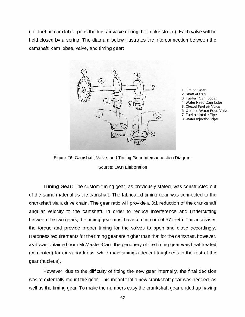
62
(i.e. fuel-air cam lobe opens the fuel-air valve during the intake stroke). Each valve will be
held closed by a spring. The diagram below illustrates the interconnection between the
camshaft, cam lobes, valve, and timing gear:
Figure 26: Camshaft, Valve, and Timing Gear Interconnection Diagram
Source: Own Elaboration
Timing Gear: The custom timing gear, as previously stated, was constructed out
of the same material as the camshaft. The fabricated timing gear was connected to the
crankshaft via a drive chain. The gear ratio will provide a 3:1 reduction of the crankshaft
angular velocity to the camshaft. In order to reduce interference and undercutting
between the two gears, the timing gear must have a minimum of 57 teeth. This increases
the torque and provide proper timing for the valves to open and close accordingly.
Hardness requirements for the timing gear are higher than that for the camshaft, however,
as it was obtained from McMaster-Carr, the periphery of the timing gear was heat treated
(cemented) for extra hardness, while maintaining a decent toughness in the rest of the
gear (nucleus).
However, due to the difficulty of fitting the new gear internally, the final decision
was to externally mount the gear. This meant that a new crankshaft gear was needed, as
well as the timing gear. To make the numbers easy the crankshaft gear ended up having
1. Timing Gear 2. Shaft of Cam 3. Fuel-air Cam Lobe 4. Water Feed Cam Lobe 5. Closed Fuel-air Valve 6. Opened Water Feed Valve 7. Fuel-air Intake Pipe 8. Water Injection Pipe
63
10 teeth and the timing gear 30, in order to make the 1/3 angular speed reduction (keeping
the same modulus).
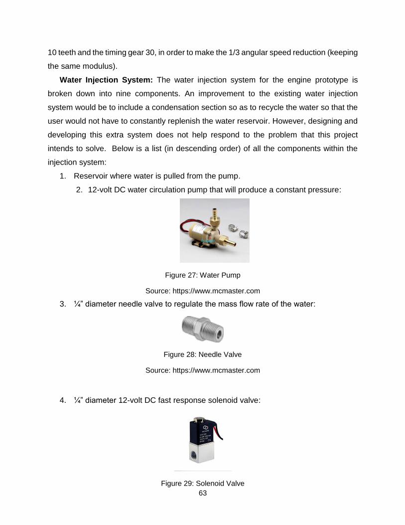
Water Injection System: The water injection system for the engine prototype is
broken down into nine components. An improvement to the existing water injection
system would be to include a condensation section so as to recycle the water so that the
user would not have to constantly replenish the water reservoir. However, designing and
developing this extra system does not help respond to the problem that this project
intends to solve. Below is a list (in descending order) of all the components within the
injection system:
1. Reservoir where water is pulled from the pump.
2. 12-volt DC water circulation pump that will produce a constant pressure:
Figure 27: Water Pump
Source: https://www.mcmaster.com
3. ¼” diameter needle valve to regulate the mass flow rate of the water:
Figure 28: Needle Valve
Source: https://www.mcmaster.com
4. ¼” diameter 12-volt DC fast response solenoid valve:
Figure 29: Solenoid Valve
64
Source: https://www.mcmaster.com
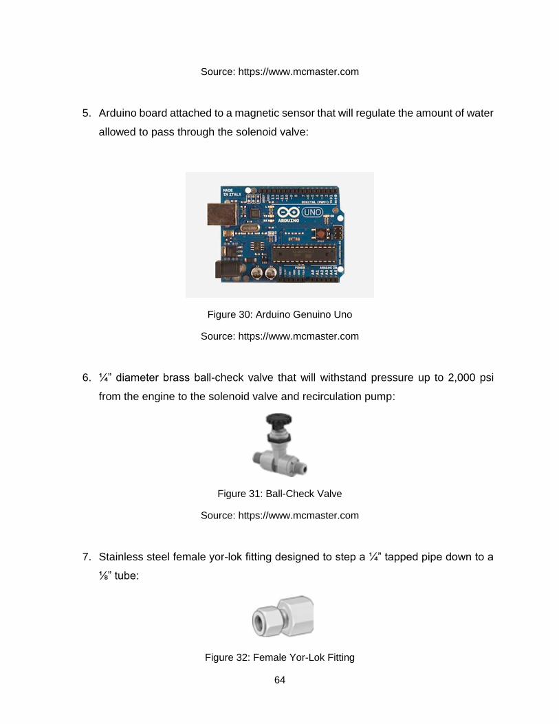
5. Arduino board attached to a magnetic sensor that will regulate the amount of water
allowed to pass through the solenoid valve:
Figure 30: Arduino Genuino Uno
Source: https://www.mcmaster.com
6. ¼” diameter brass ball-check valve that will withstand pressure up to 2,000 psi
from the engine to the solenoid valve and recirculation pump:
Figure 31: Ball-Check Valve
Source: https://www.mcmaster.com
7. Stainless steel female yor-lok fitting designed to step a ¼” tapped pipe down to a
⅛” tube:
Figure 32: Female Yor-Lok Fitting
65
Source: https://www.mcmaster.com
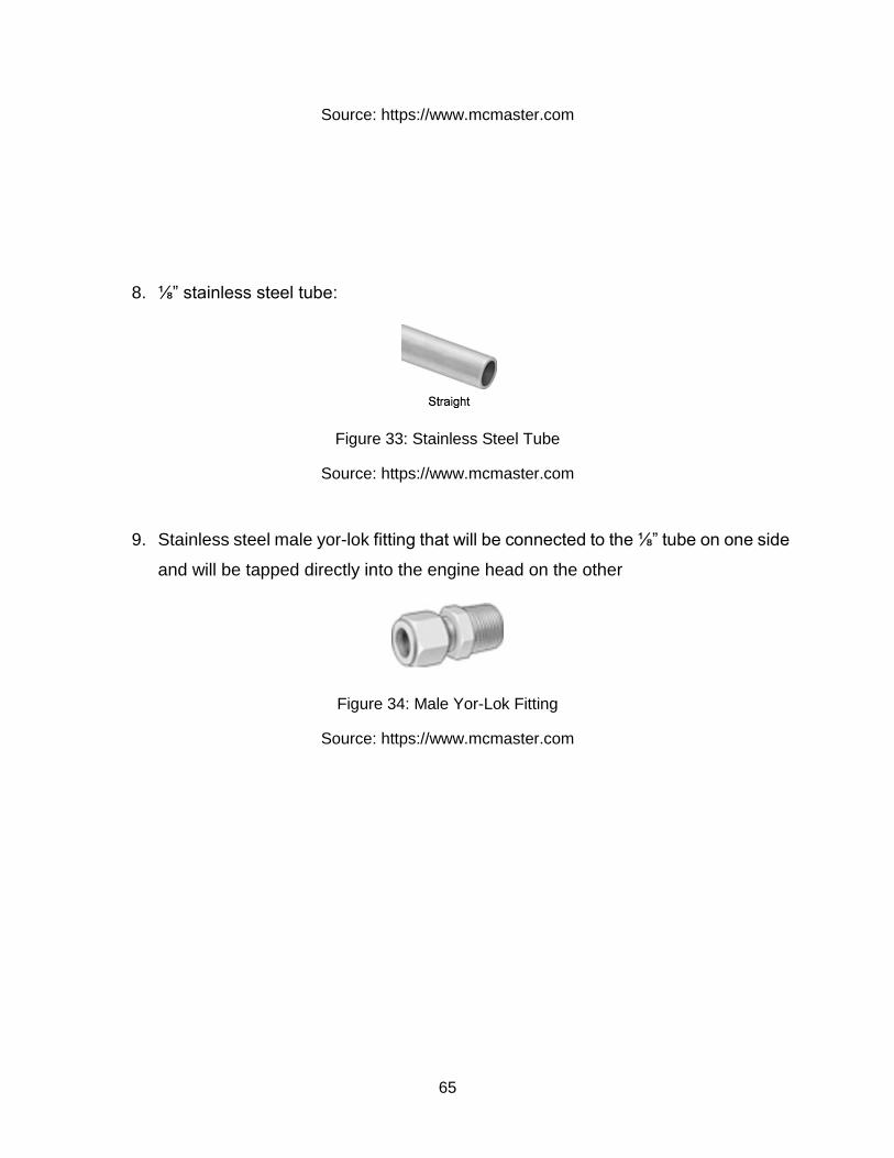
8. ⅛” stainless steel tube:
Figure 33: Stainless Steel Tube
Source: https://www.mcmaster.com
9. Stainless steel male yor-lok fitting that will be connected to the ⅛” tube on one side
and will be tapped directly into the engine head on the other
Figure 34: Male Yor-Lok Fitting
Source: https://www.mcmaster.com
66
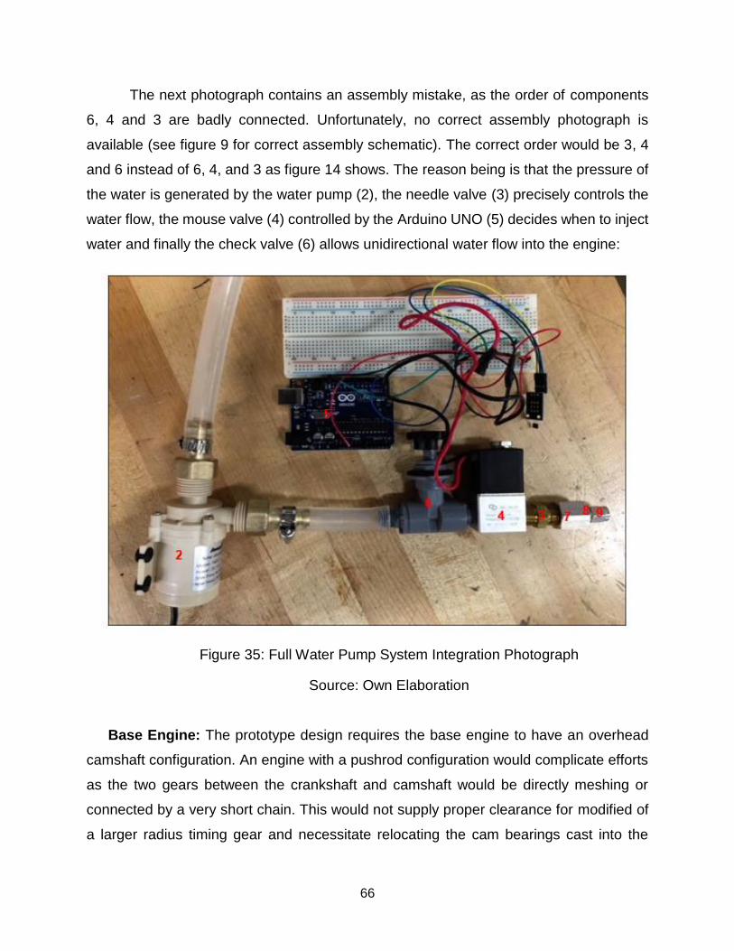
The next photograph contains an assembly mistake, as the order of components
6, 4 and 3 are badly connected. Unfortunately, no correct assembly photograph is
available (see figure 9 for correct assembly schematic). The correct order would be 3, 4
and 6 instead of 6, 4, and 3 as figure 14 shows. The reason being is that the pressure of
the water is generated by the water pump (2), the needle valve (3) precisely controls the
water flow, the mouse valve (4) controlled by the Arduino UNO (5) decides when to inject
water and finally the check valve (6) allows unidirectional water flow into the engine:
Figure 35: Full Water Pump System Integration Photograph
Source: Own Elaboration
Base Engine: The prototype design requires the base engine to have an overhead
camshaft configuration. An engine with a pushrod configuration would complicate efforts
as the two gears between the crankshaft and camshaft would be directly meshing or
connected by a very short chain. This would not supply proper clearance for modified of
a larger radius timing gear and necessitate relocating the cam bearings cast into the

67
engine block. The chosen engine was a 4 stroke, OVC, combustion engine (Honda
XR250 Dirt Bike).
68
5. Project Plan
5.1. Research
Thermodynamics and Heat Transfer:
Extensive calculations have been done above for the power production from steam
and water volume for generalized heat production levels and engine geometry, but
additional research more specific to the choice of base engine was not carried out. A
more detailed thermodynamic study could include the following topics: how much heat
the water will absorb when injected into the cylinder, what effects sudden temperature
changes will have on the piston and other hardware, how much water the engine can
vaporize given the length of the injection event and the temperature of the engine, what
mass flow rates are possible with the injector setup, and how much power and pressure
the engine can safely develop. Most of this can be accomplished through testing or simply
applying the dimensions specific to the chosen engine to the equations that have already
been derived, but some of it will can be done with physical testing. A more intensive
thermodynamic study was considered not to be essential to solve the problem this project
intends to respond to (can a 6-stroke engine produce an increase in engine efficiency?).
Stock Material:
While the materials that are used in the stock engine are known, the capability to
machine some of those materials is limited by the University of San Diego machinery and
substitutes to use for making things like the cam or timing gear had to be found. For this
the properties of various available metal stock had to be researched in order to find
something that would survive testing while costing as little as possible. Steel was the
chosen stock material for both the camshaft and the timing gear (in particular AISI 1020,
as described before), there are a variety of grades and compositions available with
different heat-treating or hardening characteristics after machining is complete. However,
as this project is not designed to last a high number of cycles so as to fatigue stresses to
come into play, machined parts were not heat treated.
69
All of the stock material was obtained from McMaster-Carr, an excellent Industrial supply
online store.
5.2. Construction
For this project, a working four stroke, overhead cam and 4-valve one-cylinder gas
engine was purchased. Several modification were needed in order to transform the four-
stroke base engine into a six-stroke engine prototype that utilizes water injection. A
custom camshaft along with cam lobes were designed and fabricated to regulate the
valves properly. Furthermore, a new timing gear system was needed to allow proper
timing from the crankshaft to the camshaft. Lastly, a water injection system operated by
an Arduino board was designed and assembled to allow precise amounts of water into
the engine cylinder.
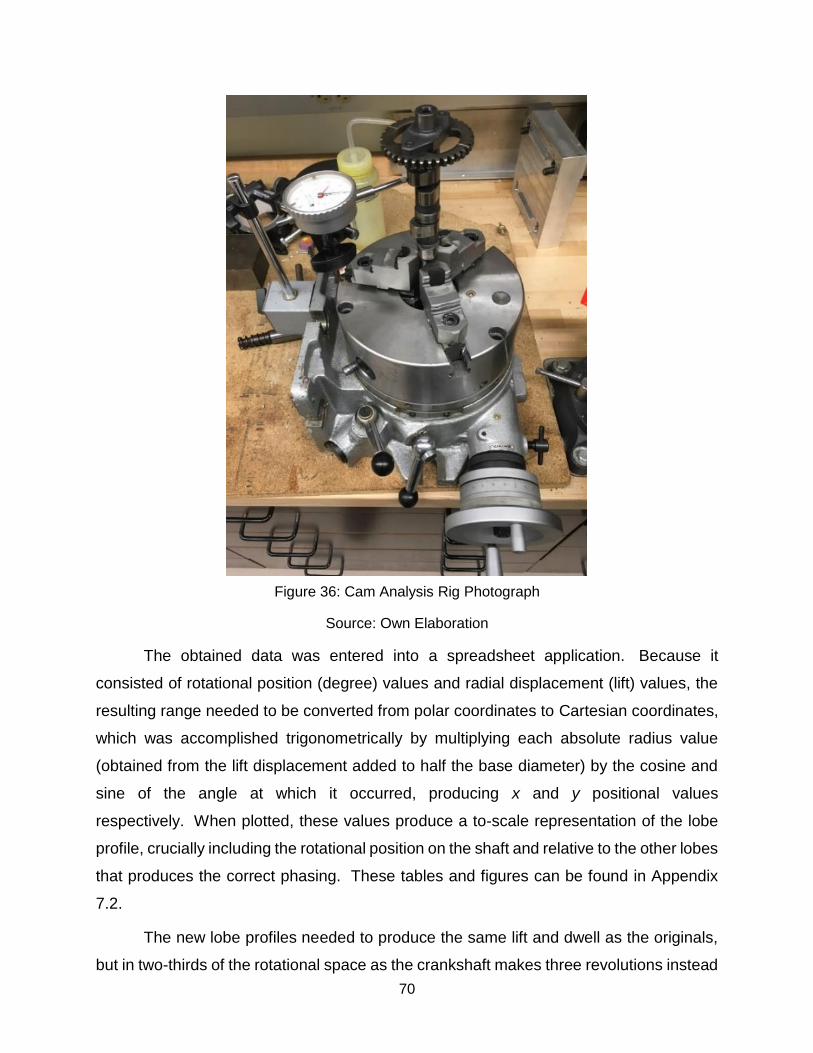
5.2.1 Camshaft Fabrication and Timing Gear Assembly
The final design of the camshaft is composed of five major parts: four individual
cam lobes, and a one-piece shaft core to mount them on. The shaft was turned on the
manual lathe and is of a stepped design allowing the cam lobes, bearings, and timing
gear to slide on from the appropriate end. Machining the cam lobes was a more involved
process. To analyze the stock cam, the shaft was mounted in an indexed chuck, and
fitted with an analog displacement gauge positioned to read the lift of a cam lobe and
zeroed at the base lobe radius. The timing marks on the stock timing gear were aligned
to zero mark on the chuck for timing reference. The assembly was then rotated through
a full 360 degrees, with readings taken every five degrees. This process was repeated
once each for the exhaust and intake cam lobes, producing 72 data points apiece. Figure
13 illustrates the rig used to conduct the cam analysis.
70
Figure 36: Cam Analysis Rig Photograph
Source: Own Elaboration
The obtained data was entered into a spreadsheet application. Because it
consisted of rotational position (degree) values and radial displacement (lift) values, the
resulting range needed to be converted from polar coordinates to Cartesian coordinates,
which was accomplished trigonometrically by multiplying each absolute radius value
(obtained from the lift displacement added to half the base diameter) by the cosine and
sine of the angle at which it occurred, producing x and y positional values
respectively. When plotted, these values produce a to-scale representation of the lobe
profile, crucially including the rotational position on the shaft and relative to the other lobes
that produces the correct phasing. These tables and figures can be found in Appendix
7.2.
The new lobe profiles needed to produce the same lift and dwell as the originals,
but in two-thirds of the rotational space as the crankshaft makes three revolutions instead
71
of two but the camshaft can still only rotate once per complete engine cycle. This means
the cam phasing needed to be reduced to two-thirds of its original amount, and profiles
themselves also needed to be compressed into two-thirds of the space on the lobe, all
while retaining the correct timing relative to the crankshaft. To accomplish this, the original
72 data points representing 360 degrees per lobe were distributed across 108 positions
representing 540 degrees of travel, with the additional spaces filled by radius values
equivalent to the base lobe radius. Since the cam cannot actually revolve 540 degrees,
the 360 degrees of cam rotation were divided evenly over the 108 positions, resulting in
a lift value every 3⅓ degrees instead of every 5. This operation compresses the lift and
dwell events by the appropriate amount, as well as positioning all two-thirds sooner
relative to the timing mark at the same time. These tables and figures can be found in
Appendix 7.3.
Unfortunately, when the 108 adjusted values are plotted over their coordinate
system, the resulting plot contains concavities due to the profile compression. The rocker
arms cannot navigate concave surfaces, so each profile was manually smoothed by
identifying the offending points and removing them from the final profile. Doing so leaves
gaps in the surface, but because the spaces in between measured points on the profile
are approximated by a straight line careful selection of the omitted values produces a
smooth tangent to the surface.
The final step was to time the steam exhaust lobe since it no longer actuates in
time with the combustion exhaust. To do this, one of the exhaust cams was simply
phased 120 degrees earlier than its counterpart, resulting in an event that occurs at the
same relative position to the piston as the combustion exhaust but two strokes earlier in
the engine cycle. Counterintuitively it is the combustion exhaust that was made earlier,
since it must occur before the steam exhaust, and the steam exhaust occurs in the original
combustion exhaust position immediately preceding the intake event. The final profiles
can be seen in Appendix 7.3.
The lobe profiles are too complex to accurately machine by hand, so a CNC
program needed to be written from the spreadsheet data. To do this, the spreadsheet x
& y values were stripped of any headings and notations, given artificial z values of zero,
and exported as a comma-separated text file. This format can be read by SolidWorks
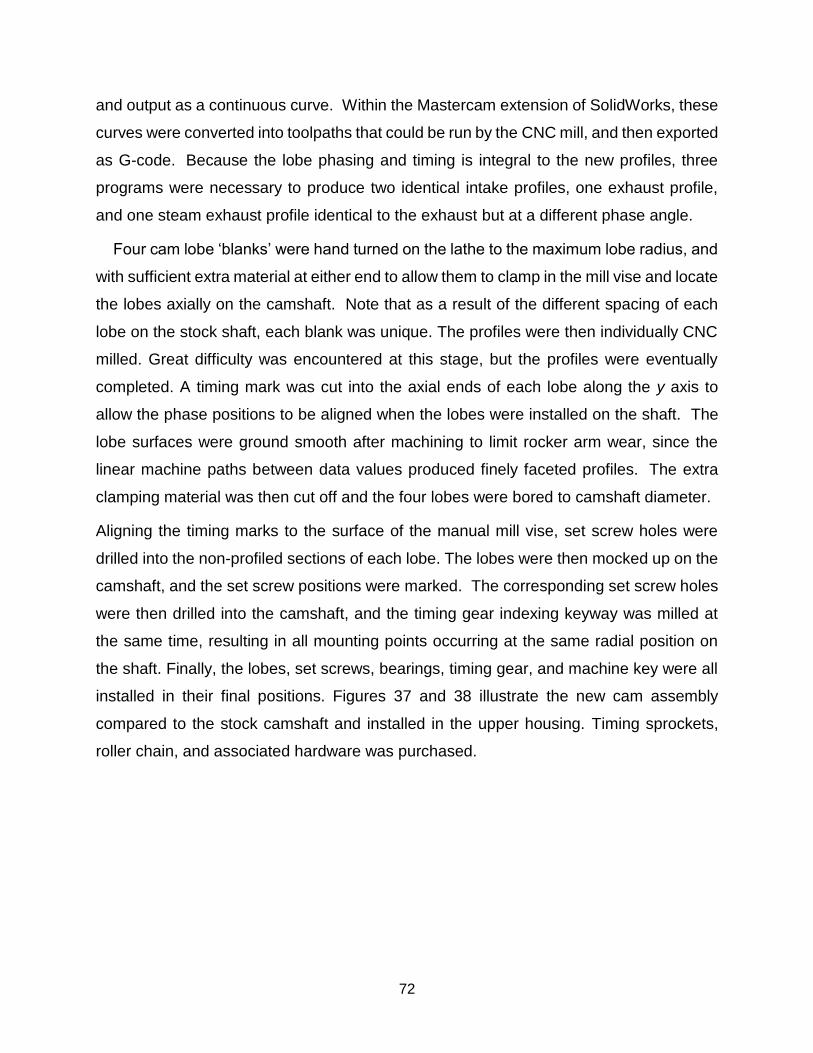
72
and output as a continuous curve. Within the Mastercam extension of SolidWorks, these
curves were converted into toolpaths that could be run by the CNC mill, and then exported
as G-code. Because the lobe phasing and timing is integral to the new profiles, three
programs were necessary to produce two identical intake profiles, one exhaust profile,
and one steam exhaust profile identical to the exhaust but at a different phase angle.
Four cam lobe ‘blanks’ were hand turned on the lathe to the maximum lobe radius, and
with sufficient extra material at either end to allow them to clamp in the mill vise and locate
the lobes axially on the camshaft. Note that as a result of the different spacing of each
lobe on the stock shaft, each blank was unique. The profiles were then individually CNC
milled. Great difficulty was encountered at this stage, but the profiles were eventually
completed. A timing mark was cut into the axial ends of each lobe along the y axis to
allow the phase positions to be aligned when the lobes were installed on the shaft. The
lobe surfaces were ground smooth after machining to limit rocker arm wear, since the
linear machine paths between data values produced finely faceted profiles. The extra
clamping material was then cut off and the four lobes were bored to camshaft diameter.
Aligning the timing marks to the surface of the manual mill vise, set screw holes were
drilled into the non-profiled sections of each lobe. The lobes were then mocked up on the
camshaft, and the set screw positions were marked. The corresponding set screw holes
were then drilled into the camshaft, and the timing gear indexing keyway was milled at
the same time, resulting in all mounting points occurring at the same radial position on
the shaft. Finally, the lobes, set screws, bearings, timing gear, and machine key were all
installed in their final positions. Figures 37 and 38 illustrate the new cam assembly
compared to the stock camshaft and installed in the upper housing. Timing sprockets,
roller chain, and associated hardware was purchased.
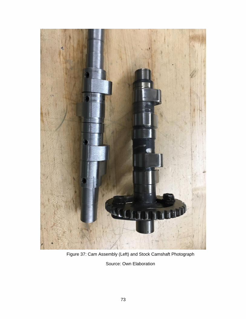
73
Figure 37: Cam Assembly (Left) and Stock Camshaft Photograph
Source: Own Elaboration
74
Figure 38: Cam Assembly and Timing Gear Installed
Source: Own Elaboration
75
5.2.2 Water Injection System Assembly
The water injection system, that is broken down into ten components as stated
above (see section 3.3), will be drilled directly into the engine cylinder. Pulling water from
the reservoir, a DC water circulation pump provides the system with sufficient pressure
for the water to enter into the engine cylinder. The water is pumped into the needle valve
to allow for a precise amount of mass flow rate of the water through the system (see
section 5.2.1). Next, the water is pumped into the solenoid valve. Operated by the Arduino
board, the solenoid valve will only open for short durations to allow a finite amount of
water to pass through. A magnetic sensor is attached to the camshaft that will sent a
signal to the Arduino during the fifth stroke.
Since the engine cylinder experiences high degrees of pressure, a ball-check valve
is installed to order to stop the high levels of pressure from damaging the solenoid valve,
needle valve and pump. The ball-check can withstand pressure of 2000 Psi in one
direction, yet opens with pressure of 2-5 Psi in the direction of the water flow.
Furthermore, the two Yor-lok fittings and ⅛” tubing can withstand pressure up to 7,000
Psi. See figure X for full water injection system assembly.
As for the microcontroller, the breadboard circuit used the following components:
1. The previously stated solenoid valve.
2. An Arduino Uno microcontroller.
3. A solderless breadboard.
4. One TIP120 Darlington Transistor.
5. One 1K Ohm Resistor.
6. One 1N4001 Diode.
7. Hookup Wires.
Using the previous components and the following schematics, the following circuit
was designed:
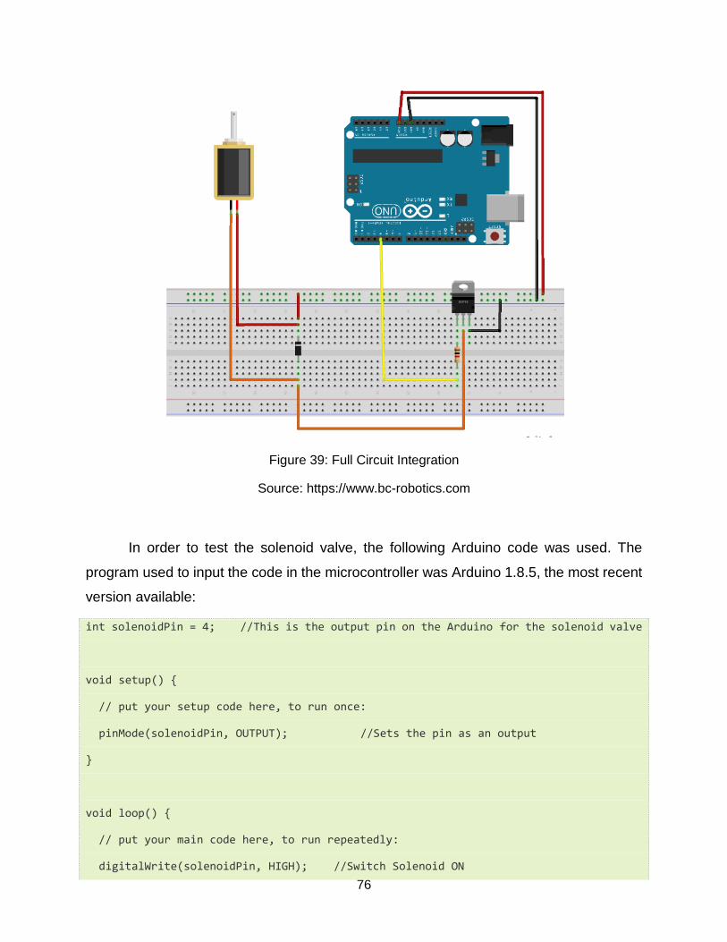
76
Figure 39: Full Circuit Integration
Source: https://www.bc-robotics.com
In order to test the solenoid valve, the following Arduino code was used. The
program used to input the code in the microcontroller was Arduino 1.8.5, the most recent
version available:
int solenoidPin = 4; //This is the output pin on the Arduino for the solenoid valve
void setup() {
// put your setup code here, to run once:
pinMode(solenoidPin, OUTPUT); //Sets the pin as an output
}
void loop() {
// put your main code here, to run repeatedly:
digitalWrite(solenoidPin, HIGH); //Switch Solenoid ON
77
delay(1000); //Wait 1 Second
digitalWrite(solenoidPin, LOW); //Switch Solenoid OFF
delay(1000); // Wait 1 second
The purpose of this program, specifically the timing, was written to electronically
test the solenoid valve. It really only turns on and off the solenoid valve, with a delay of
1000 ms seconds (1 second) between the ON and OFF states.
As stated previously, for the full 6-stroke engine integration, a magnetic sensor
was introduced to the camshaft. For each cycle, the purpose of this sensor is to turn ON
(during water injection) and OFF (the rest of the time) the solenoid valve. A LED light was
added for visual purposes (to check when the valve is ON and OFF). The following code
accounts for this modification:
int solenoidPin = 4; //This is the output pin on the Arduino for the solenoid valve
int magnetic_sensor = 2;
int inputVal = 0;
void setup() {
// put your setup code here, to run once:
pinMode(solenoidPin, OUTPUT); //Sets the pin as an output
pinMode(13, OUTPUT); //LED (only for visual purposes)
pinMode(magnetic_sensor, INPUT);
}
void loop() {
if(digitalRead(magnetic_sensor)==HIGH) //Check the sensor output
{
digitalWrite(13, HIGH); // set the LED on
digitalWrite(solenoidPin, HIGH); //Switch Solenoid ON
}
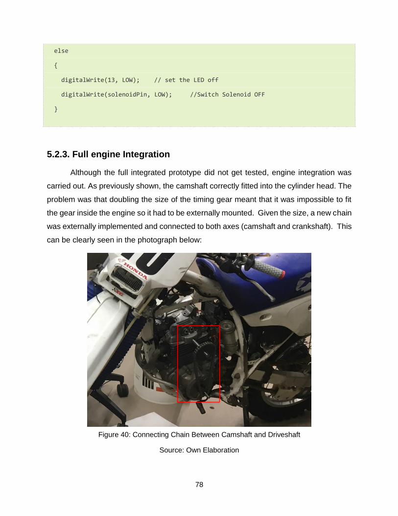
78
else
{
digitalWrite(13, LOW); // set the LED off
digitalWrite(solenoidPin, LOW); //Switch Solenoid OFF
}
5.2.3. Full engine Integration
Although the full integrated prototype did not get tested, engine integration was
carried out. As previously shown, the camshaft correctly fitted into the cylinder head. The
problem was that doubling the size of the timing gear meant that it was impossible to fit
the gear inside the engine so it had to be externally mounted. Given the size, a new chain
was externally implemented and connected to both axes (camshaft and crankshaft). This
can be clearly seen in the photograph below:
Figure 40: Connecting Chain Between Camshaft and Driveshaft
Source: Own Elaboration
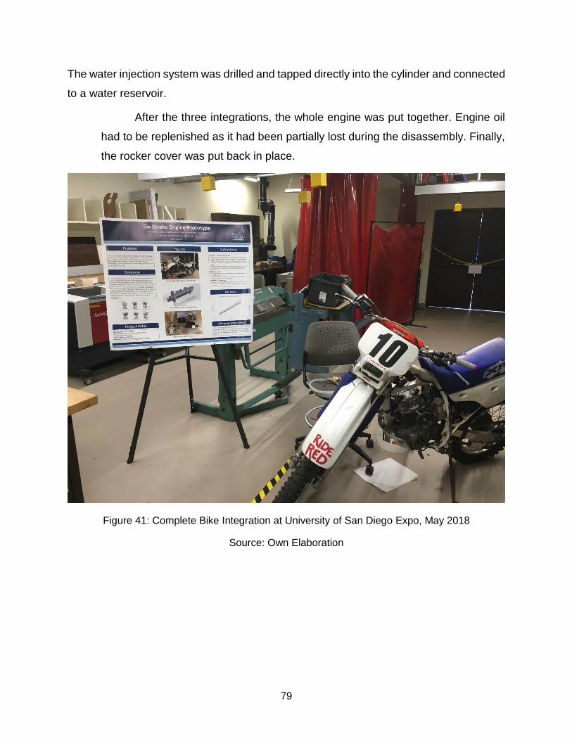
79
The water injection system was drilled and tapped directly into the cylinder and connected
to a water reservoir.
After the three integrations, the whole engine was put together. Engine oil
had to be replenished as it had been partially lost during the disassembly. Finally,
the rocker cover was put back in place.
Figure 41: Complete Bike Integration at University of San Diego Expo, May 2018
Source: Own Elaboration
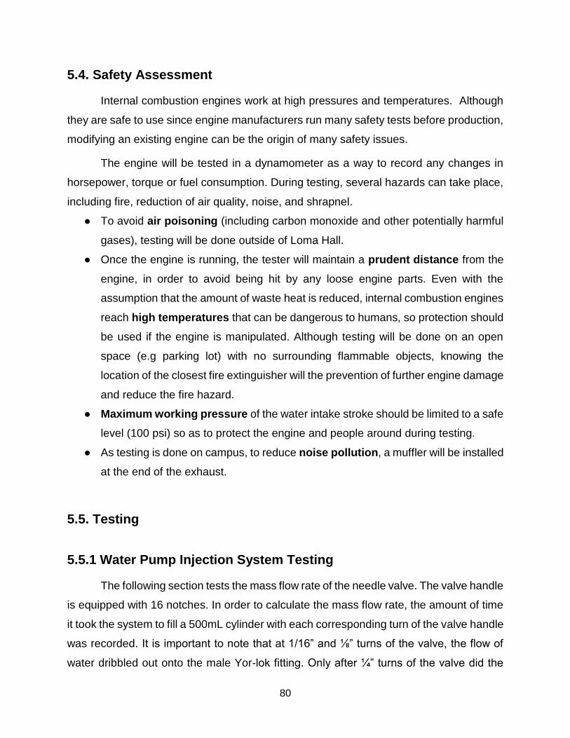
80
5.4. Safety Assessment
Internal combustion engines work at high pressures and temperatures. Although
they are safe to use since engine manufacturers run many safety tests before production,
modifying an existing engine can be the origin of many safety issues.
The engine will be tested in a dynamometer as a way to record any changes in
horsepower, torque or fuel consumption. During testing, several hazards can take place,
including fire, reduction of air quality, noise, and shrapnel.
● To avoid air poisoning (including carbon monoxide and other potentially harmful
gases), testing will be done outside of Loma Hall.
● Once the engine is running, the tester will maintain a prudent distance from the
engine, in order to avoid being hit by any loose engine parts. Even with the
assumption that the amount of waste heat is reduced, internal combustion engines
reach high temperatures that can be dangerous to humans, so protection should
be used if the engine is manipulated. Although testing will be done on an open
space (e.g parking lot) with no surrounding flammable objects, knowing the
location of the closest fire extinguisher will the prevention of further engine damage
and reduce the fire hazard.
● Maximum working pressure of the water intake stroke should be limited to a safe
level (100 psi) so as to protect the engine and people around during testing.
● As testing is done on campus, to reduce noise pollution, a muffler will be installed
at the end of the exhaust.
5.5. Testing
5.5.1 Water Pump Injection System Testing
The following section tests the mass flow rate of the needle valve. The valve handle
is equipped with 16 notches. In order to calculate the mass flow rate, the amount of time
it took the system to fill a 500mL cylinder with each corresponding turn of the valve handle
was recorded. It is important to note that at 1/16” and ⅛” turns of the valve, the flow of
water dribbled out onto the male Yor-lok fitting. Only after ¼” turns of the valve did the

81
flow of water begin to produce a steady stream. Data resembled a logarithmic
relationship, spiking at the 1/16” and ⅛” turns of the valve. After 2 turns of the valve, the
amount to time that it took to fill the 500mL was negligible.
Figure 42: Number of Needle Valve Turns Vs Time to Fill 500ml Cylinder
Source: Own Elaboration
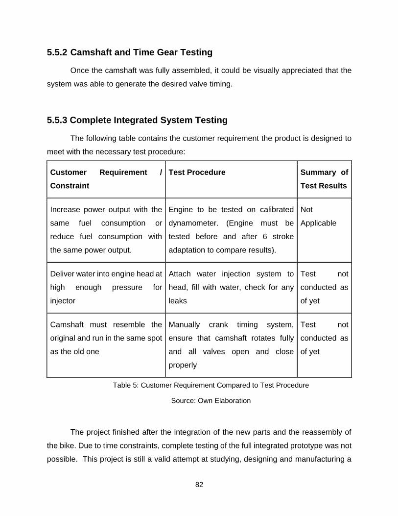
82
5.5.2 Camshaft and Time Gear Testing
Once the camshaft was fully assembled, it could be visually appreciated that the
system was able to generate the desired valve timing.
5.5.3 Complete Integrated System Testing
The following table contains the customer requirement the product is designed to
meet with the necessary test procedure:
Customer Requirement /
Constraint
Test Procedure Summary of
Test Results
Increase power output with the
same fuel consumption or
reduce fuel consumption with
the same power output.
Engine to be tested on calibrated
dynamometer. (Engine must be
tested before and after 6 stroke
adaptation to compare results).
Not
Applicable
Deliver water into engine head at
high enough pressure for
injector
Attach water injection system to
head, fill with water, check for any
leaks
Test not
conducted as
of yet
Camshaft must resemble the
original and run in the same spot
as the old one
Manually crank timing system,
ensure that camshaft rotates fully
and all valves open and close
properly
Test not
conducted as
of yet
Table 5: Customer Requirement Compared to Test Procedure
Source: Own Elaboration
The project finished after the integration of the new parts and the reassembly of
the bike. Due to time constraints, complete testing of the full integrated prototype was not
possible. This project is still a valid attempt at studying, designing and manufacturing a
83
six-stroke water injection engine. Unfortunately, experimental data to back up the
previous customer requirements/constraints and previous theory is not available.
Nevertheless, the engine was successfully started and run for a time span of 10
minutes approximately. 5 minutes were needed for the engine to heat up before starting
the water injection (the engine was still running).
Even though the bike got to work, without experimental data it is impossible to
detect if the water is actually powering the bike, or if both final strokes do not produce any
power (the flywheel does the work during those strokes). Unfortunately, there was no time
to test on a calibrated dynamometer, which is the only way to find out about the previous
statement.
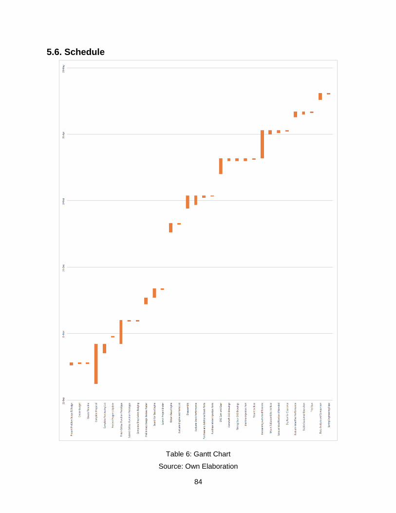
84
5.6. Schedule
Table 6: Gantt Chart
Source: Own Elaboration
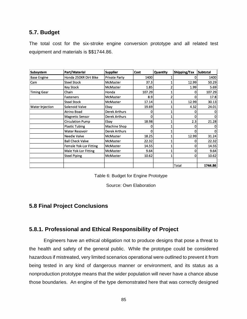
85
5.7. Budget
The total cost for the six-stroke engine conversion prototype and all related test
equipment and materials is $$1744.86.
Table 6: Budget for Engine Prototype
Source: Own Elaboration
5.8 Final Project Conclusions
5.8.1. Professional and Ethical Responsibility of Project
Engineers have an ethical obligation not to produce designs that pose a threat to
the health and safety of the general public. While the prototype could be considered
hazardous if mistreated, very limited scenarios operational were outlined to prevent it from
being tested in any kind of dangerous manner or environment, and its status as a
nonproduction prototype means that the wider population will never have a chance abuse
those boundaries. An engine of the type demonstrated here that was correctly designed
86
from scratch and build for the purpose would pose no greater ethical problems than any
existing engine currently in production.
5.8.2. Lifelong Learning Contribution of Project
This project involved fairly significant, highly involved, and widely varied
mechanical engineering problems including: reverse engineering, part design, CAD
design, part selection, manufacturability design, material selection, and hand and CNC
machining. These problems were very appropriate for a mechanical engineering project,
and it is surprising how truly interconnected the various fields are. There was also a
necessity to draw heavily on fluid dynamics and electrical engineering knowledge over
the course of the project. Additionally, for the construction of the bike the group realized
the importance of dividing work since there was far more than any one person could do
and by specializing the results were obtained easily and efficiently. In addition, the group
was also surprise by how large of some impact administrative obstacles can have on
timelines, and that there is a maximum number of delays and setbacks a timeline can
handle. Most importantly however, from this project it was learned that even ambitious,
problematic projects can be accomplished with enough planning and cooperation.
5.8.3. Global, Economic, and Environmental Impact of and to Project
The introduction of an internal combustion engine that can effectively utilize waste
heat has obviously major ramifications in a world where such engines are so prevalent
and essential. This combustion cycle is meant to do this by vaporizing water to convert
stored and exhaust heat into pressure and usable work within the operation of the engine,
producing greater and smoother power without additional fuel consumption, ancillary
equipment, or undeveloped technology. Reduced consumption of hydrocarbon fuels
would have wide-reaching economic consequences and direly needed environmental
effects with the associated reduction in oil purchases and atmospheric emissions, but
engines like the one designed prototyped for this project have existed for some time now
without garnering much attention or interest. There is presumably a reason, given the
high demand for efficiency it is unlikely that such developments went unnoticed by
industry, and one of the main goals of this project was to understand what that reason is.
87
Unfortunately, while the prototype was successfully constructed, time and facilities
constraints prevented proper testing, so it can only be speculated as to what that reason
might be.
5.8.5. Results
As stated previously in the testing section, full integration testing was unfortunately
not possible. However, the water injection system successfully produced the water
injection flow the engine needed for the full integration. The camshaft and the timing gear
were also both successful in producing the desired timing for a six-stroke cycle.
Even though all subsystems where correctly manufactured, it was not possible to test the
bike to see if any efficiency improvements were made. However, the bike did get to run
for a short amount of time (10 minutes), enough to test the injection system. However, as
previously stated, without proper testing in a calibrated dynamometer, improvements in
power and/or efficiency cannot be visually detected.
5.8.6. The validity of findings and recommendations for future studies
The fact that six-stroke engines utilize a technology that is not yet rooted into the
engine industry was one of the motives to study, design and manufacture its own water
injection engine. Someone with a glint of common sense would certain ponder upon the
following question: if this technology or similar technologies like the ones described in the
state of the art supposedly obtain a significant increase in efficiency, emissions and power
why does not it find its way into the engine market?
Thousands of engine business have dedicated R&D teams constantly looking for
new and effective ways to improve existing engines, or create new ones. However,
sometimes the benefit new technologies bring is unable to unseat previous, stablished
already working technologies. This unseating generally requires a high initial investment
to achieve a good market acceptance. The scope of this study was straightforward: can
a working 6 stroke water injection prototype be created, and can it increase efficiency or
power?
Therefore, recommendations for future studies include the following. Once
increases in efficiency, reduced fuel consumption or increases in power have been

88
demonstrated, the application of such engine should be heavily studied. This will depend
on the system the engine will be integrated to. Maybe the weight of the water tank it needs
outweighs the efficiency improvement. Maybe the increase in size and weight makes it
difficult to create small, lightweight, powerful cars. Maybe the high initial investment
hinders its expansion capabilities. Thus, an exhaustive, complete integration study of the
engine into an existing vehicle or machine that incorporates the previous factors and
economic considerations is highly recommended.
Finally, I consider that the fact that this engine has not been developed does not
necessarily mean it is the wrong way to go. In fact, in this case it is completely the
opposite: this should serve as a hint for future studies to consider the downsides of the
technology and find ways to improve or reduce their negative effect. I still think that even
the slightest improvement in fuel efficiency can outweigh a high product price, as fuel
economics (especially in commercial use) clearly surpasses the initial price of the majority
of all market-available machines.
89
6. References
[1] Automotive Industry. (n.d). Retrieved on the 14 of May 2018, from
www.selectusa.gov/automotive-industry-united-states.
[2] Global Car Sales 1990-2017. (n.d). Retrieved on the 20 of May 2018, from
www.statista.com/statistics/200002/international-car-sales-since-1990/.
[3] Where the Energy Goes: Gasoline Vehicles. (n.d). Retrieved on the 3 of February, from
www.fueleconomy.gov/feg/atv.shtml.
[4] Lyons, P. (2006, February 26). Inside Bruce Crower's Six-Stroke Engine. Autoweek.
Retrieved on the 12 of March 2018, from http://autoweek.com/article/car-news/inside-
bruce-crowers-six-stroke-engine
[5] Raza, M. (n.d). Study and analysis of six stroke internal combustion engine. Retrieved
on the 15 of March 2018, from the Department of Mechanical Engineering of JSS
Academy of Technical Education: https://www.ijedr.org/papers/IJEDR1703167.pdf

90
7. Appendices
7.1. Cam Analysis Tables
7.1.1. Intake Analysis
* D R X Y Z
0 0 0.433071 0.433071 0 0
5 0 0.433071 0.4314230341 0.03774462467 0
10 0 0.433071 0.4264916784 0.07520198995 0
15 2 0.435071 0.4202463152 0.1126046608 0
20 7 0.440071 0.4135314713 0.1505131465 0
25 13 0.446071 0.4042776209 0.1885177506 0
30 23 0.456071 0.3949690719 0.2280355 0
35 35 0.468071 0.3834213165 0.2684744961 0
40 51 0.484071 0.3708198996 0.311154841 0
45 72 0.505071 0.3571391291 0.3571391291 0
50 97 0.530071 0.3407230711 0.406057944 0
55 127 0.560071 0.3212435283 0.4587833046 0
60 158 0.591071 0.2955355 0.5118825014 0
65 188 0.621071 0.2624759464 0.5628814836 0
70 218 0.651071 0.2226793967 0.6118066143 0
75 238 0.671071 0.1736859554 0.6482048102 0
80 255 0.688071 0.1194822753 0.6776176554 0
85 264 0.697071 0.06075374075 0.6944184344 0
90 270 0.703071 0 0.703071 0
95 272 0.705071 -0.06145098669 0.702387992 0
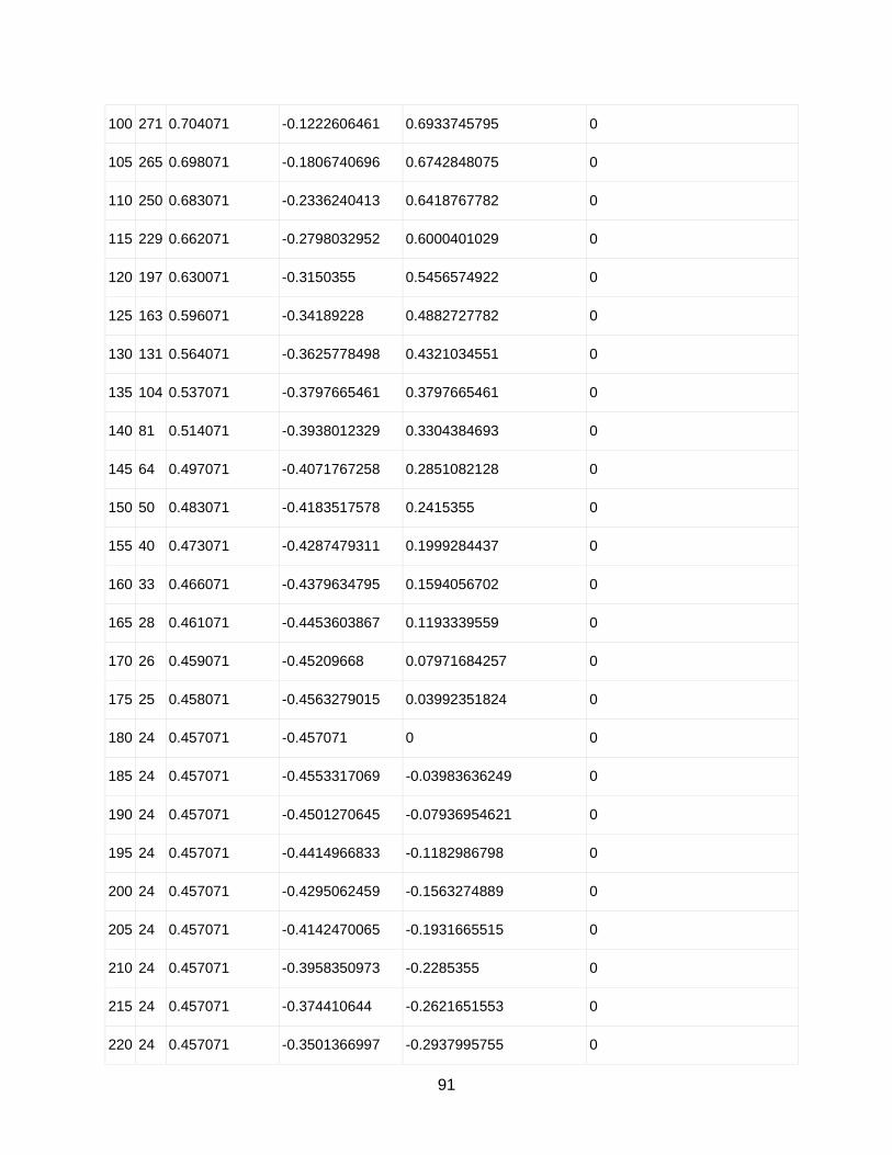
91
100 271 0.704071 -0.1222606461 0.6933745795 0
105 265 0.698071 -0.1806740696 0.6742848075 0
110 250 0.683071 -0.2336240413 0.6418767782 0
115 229 0.662071 -0.2798032952 0.6000401029 0
120 197 0.630071 -0.3150355 0.5456574922 0
125 163 0.596071 -0.34189228 0.4882727782 0
130 131 0.564071 -0.3625778498 0.4321034551 0
135 104 0.537071 -0.3797665461 0.3797665461 0
140 81 0.514071 -0.3938012329 0.3304384693 0
145 64 0.497071 -0.4071767258 0.2851082128 0
150 50 0.483071 -0.4183517578 0.2415355 0
155 40 0.473071 -0.4287479311 0.1999284437 0
160 33 0.466071 -0.4379634795 0.1594056702 0
165 28 0.461071 -0.4453603867 0.1193339559 0
170 26 0.459071 -0.45209668 0.07971684257 0
175 25 0.458071 -0.4563279015 0.03992351824 0
180 24 0.457071 -0.457071 0 0
185 24 0.457071 -0.4553317069 -0.03983636249 0
190 24 0.457071 -0.4501270645 -0.07936954621 0
195 24 0.457071 -0.4414966833 -0.1182986798 0
200 24 0.457071 -0.4295062459 -0.1563274889 0
205 24 0.457071 -0.4142470065 -0.1931665515 0
210 24 0.457071 -0.3958350973 -0.2285355 0
215 24 0.457071 -0.374410644 -0.2621651553 0
220 24 0.457071 -0.3501366997 -0.2937995755 0

92
225 24 0.457071 -0.3231980036 -0.3231980036 0
230 24 0.457071 -0.2937995755 -0.3501366997 0
235 24 0.457071 -0.2621651553 -0.374410644 0
240 24 0.457071 -0.2285355 -0.3958350973 0
245 24 0.457071 -0.1931665515 -0.4142470065 0
250 24 0.457071 -0.1563274889 -0.4295062459 0
255 24 0.457071 -0.1182986798 -0.4414966833 0
260 24 0.457071 -0.07936954621 -0.4501270645 0
265 23 0.456071 -0.03974920675 -0.4543355122 0
270 22 0.455071 0 -0.455071 0
275 20 0.453071 0.03948773952 -0.4513469281 0
280 20 0.453071 0.0786749535 -0.4461878335 0
285 19 0.452071 0.1170045845 -0.4366670542 0
290 18 0.451071 0.1542753681 -0.4238680902 0
295 17 0.450071 0.1902082237 -0.407902852 0
300 16 0.449071 0.2245355 -0.3889068941 0
305 14 0.447071 0.256429391 -0.3662191236 0
310 13 0.446071 0.2867289118 -0.3417102108 0
315 12 0.445071 0.3147127222 -0.3147127222 0
320 11 0.444071 0.3401781219 -0.2854433366 0
325 10 0.443071 0.3629425154 -0.2541350852 0
330 9 0.442071 0.3828447163 -0.2210355 0
335 7 0.440071 0.3988397741 -0.1859820411 0
340 6 0.439071 0.4125917787 -0.1501711264 0
345 4 0.437071 0.4221781668 -0.1131222989 0
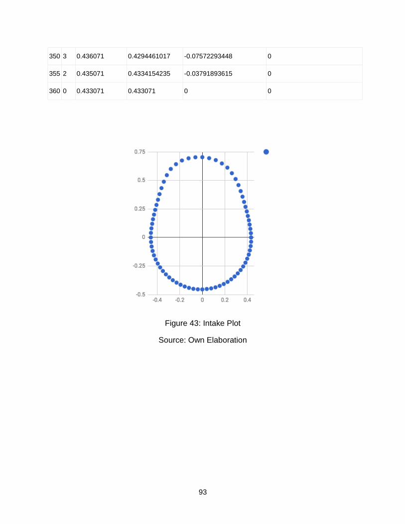
93
350 3 0.436071 0.4294461017 -0.07572293448 0
355 2 0.435071 0.4334154235 -0.03791893615 0
360 0 0.433071 0.433071 0 0
Figure 43: Intake Plot
Source: Own Elaboration

94
7.1.2 Exhaust Analysis
* D R X Y Z
0 105 0.558017 0.558017 0 0
5 137 0.590017 0.5877718072 0.05142336987 0
10 172 0.625017 0.6155215874 0.1085330631 0
15 203 0.656017 0.6336637628 0.1697896935 0
20 226 0.679017 0.6380672643 0.2322374917 0
25 238 0.691017 0.6262740881 0.2920364034 0
30 242 0.695017 0.6019023781 0.3475085 0
35 243 0.696017 0.5701437484 0.3992189505 0
40 242 0.695017 0.5324139107 0.4467483161 0
45 240 0.693017 0.4900370202 0.4900370202 0
50 224 0.677017 0.4351781391 0.5186251107 0
55 208 0.661017 0.3791437752 0.5414734269 0
60 185 0.638017 0.3190085 0.55253893 0
65 158 0.611017 0.2582269424 0.5537694651 0
70 127 0.580017 0.1983774975 0.5450376948 0
75 98 0.551017 0.1426136938 0.532241551 0
80 71 0.524017 0.09099459712 0.5160560043 0
85 50 0.503017 0.04384082025 0.5011028685 0
90 31 0.484017 0 0.484017 0
95 14 0.467017 -0.04070321351 0.4652398593 0
100 2 0.455017 -0.07901287286 0.4481042694 0
105 -7 0.446017 -0.115437694 0.4308193393 0

95
110 -13 0.440017 -0.1504946774 0.4134807279 0
115 -17 0.436017 -0.1842687466 0.3951656024 0
120 -20 0.433017 -0.2165085 0.3750037223 0
125 -20 0.433017 -0.2483683477 0.3547067608 0
130 -20 0.433017 -0.2783379624 0.3317102666 0
135 -19 0.434017 -0.3068963639 0.3068963639 0
140 -18 0.435017 -0.3332423555 0.2796235376 0
145 -17 0.436017 -0.3571642169 0.250089077 0
150 -15 0.438017 -0.3793338493 0.2190085 0
155 -14 0.439017 -0.3978845257 0.1855366014 0
160 -12 0.441017 -0.4144204205 0.1508366975 0
165 -11 0.442017 -0.426955636 0.1144024179 0
170 -10 0.443017 -0.4362865763 0.07692909473 0
175 -9 0.444017 -0.4423273813 0.03869863143 0
180 -8 0.445017 -0.445017 0 0
185 -7 0.446017 -0.4443197707 -0.03887294291 0
190 -5 0.448017 -0.4412106151 -0.07779733561 0
195 -4 0.449017 -0.4337171167 -0.1162141512 0
200 -3 0.450017 -0.4228776541 -0.1539148788 0
205 -2 0.451017 -0.4087602192 -0.1906080206 0
210 -2 0.451017 -0.3905921795 -0.2255085 0
215 -1 0.452017 -0.3702706496 -0.2592663 0
220 -1 0.452017 -0.346265111 -0.290550927 0
225 0 0.453017 -0.3203313927 -0.3203313927 0
230 1 0.454017 -0.2918365022 -0.3477971999 0
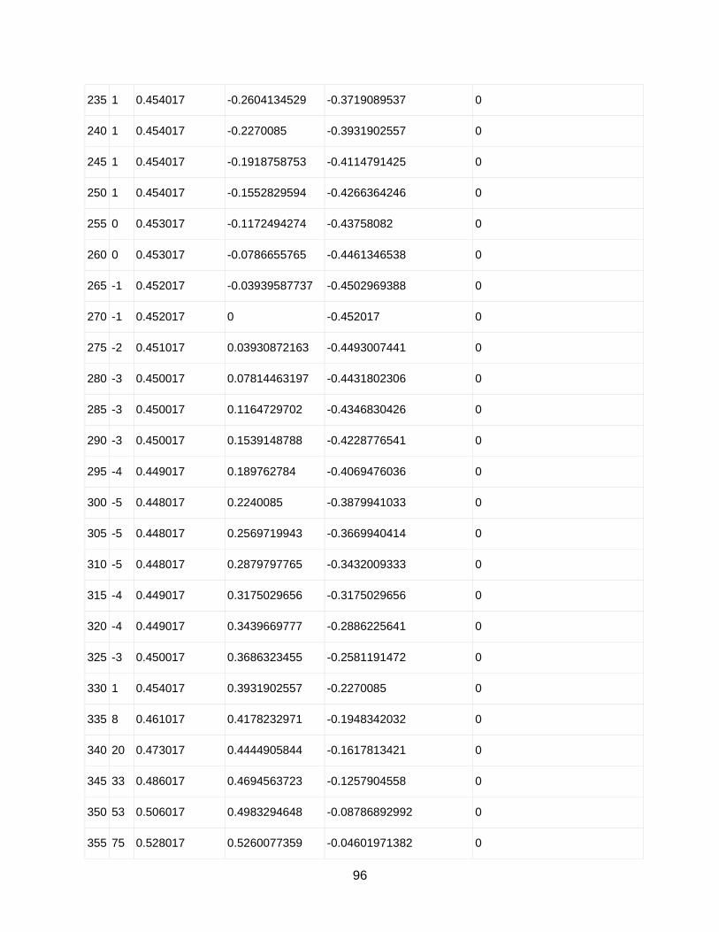
96
235 1 0.454017 -0.2604134529 -0.3719089537 0
240 1 0.454017 -0.2270085 -0.3931902557 0
245 1 0.454017 -0.1918758753 -0.4114791425 0
250 1 0.454017 -0.1552829594 -0.4266364246 0
255 0 0.453017 -0.1172494274 -0.43758082 0
260 0 0.453017 -0.0786655765 -0.4461346538 0
265 -1 0.452017 -0.03939587737 -0.4502969388 0
270 -1 0.452017 0 -0.452017 0
275 -2 0.451017 0.03930872163 -0.4493007441 0
280 -3 0.450017 0.07814463197 -0.4431802306 0
285 -3 0.450017 0.1164729702 -0.4346830426 0
290 -3 0.450017 0.1539148788 -0.4228776541 0
295 -4 0.449017 0.189762784 -0.4069476036 0
300 -5 0.448017 0.2240085 -0.3879941033 0
305 -5 0.448017 0.2569719943 -0.3669940414 0
310 -5 0.448017 0.2879797765 -0.3432009333 0
315 -4 0.449017 0.3175029656 -0.3175029656 0
320 -4 0.449017 0.3439669777 -0.2886225641 0
325 -3 0.450017 0.3686323455 -0.2581191472 0
330 1 0.454017 0.3931902557 -0.2270085 0
335 8 0.461017 0.4178232971 -0.1948342032 0
340 20 0.473017 0.4444905844 -0.1617813421 0
345 33 0.486017 0.4694563723 -0.1257904558 0
350 53 0.506017 0.4983294648 -0.08786892992 0
355 75 0.528017 0.5260077359 -0.04601971382 0
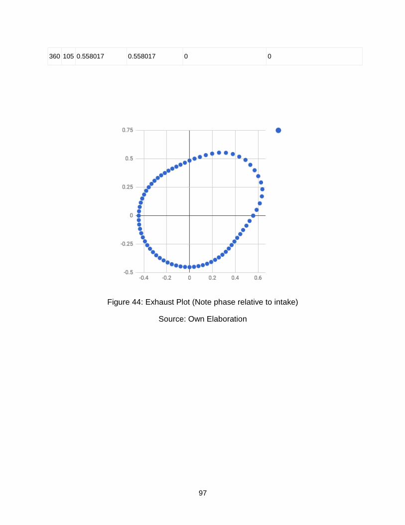
97
360 105 0.558017 0.558017 0 0
Figure 44: Exhaust Plot (Note phase relative to intake)
Source: Own Elaboration
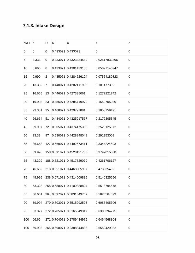
98
7.1.3. Intake Design
*REF * D R X Y Z
0 0 0 0.433071 0.433071 0 0
5 3.333 0 0.433071 0.4323384589 0.02517832396 0
10 6.666 0 0.433071 0.4301433138 0.05027146947 0
15 9.999 2 0.435071 0.4284626124 0.07554180823 0
20 13.332 7 0.440071 0.4282111908 0.101477392 0
25 16.665 13 0.446071 0.427335061 0.1279221742 0
30 19.998 23 0.456071 0.4285719979 0.1559705089 0
35 23.331 35 0.468071 0.429797881 0.1853759491 0
40 26.664 51 0.484071 0.4325917567 0.2172305345 0
45 29.997 72 0.505071 0.4374175388 0.2525125972 0
50 33.33 97 0.530071 0.4428848048 0.291253008 0
55 36.663 127 0.560071 0.4492673411 0.3344224593 0
60 39.996 158 0.591071 0.4528131783 0.3799015038 0
65 43.329 188 0.621071 0.4517829079 0.4261706127 0
70 46.662 218 0.651071 0.4468305997 0.473535492 0
75 49.995 238 0.671071 0.4314009835 0.5140325656 0
80 53.328 255 0.688071 0.4109388824 0.5518794578 0
85 56.661 264 0.697071 0.3831043709 0.5823564373 0
90 59.994 270 0.703071 0.3515992596 0.6088405306 0
95 63.327 272 0.705071 0.3165049317 0.6300394775 0
100 66.66 271 0.704071 0.2789434975 0.6464568804 0
105 69.993 265 0.698071 0.2388344838 0.6559429932 0

99
110 73.326 250 0.683071 0.1959907233 0.6543497745 0
115 76.659 229 0.662071 0.1527702816 0.6442043543 0
120 79.992 197 0.630071 0.1094973179 0.6204835231 0
125 83.325 163 0.596071 0.0692857275 0.5920305102 0
130 86.658 131 0.564071 0.03288298949 0.5631117136 0
135 89.991 104 0.537071 0.00008436291506 0.5370709934 0
140 93.324 81 0.514071 -0.0298069708 0.5132061355 0
145 96.657 64 0.497071 -0.05762312374 0.4937197126 0
150 99.99 50 0.483071 -0.08380136665 0.4757466994 0
155 103.323 40 0.473071 -0.1090146599 0.4603389783 0
160 106.656 33 0.466071 -0.1335875446 0.4465160075 0
165 109.989 28 0.461071 -0.1576123857 0.4332952837 0
170 113.322 26 0.459071 -0.1817453511 0.4215623446 0
175 116.655 25 0.458071 -0.205498533 0.4093890496 0
180 119.988 24 0.457071 -0.2284525915 0.395882953 0
185 123.321 24 0.457071 -0.2510824104 0.3819313056 0
190 126.654 24 0.457071 -0.2728628159 0.366687582 0
195 129.987 24 0.457071 -0.2937201245 0.3502033517 0
200 133.32 24 0.457071 -0.3135837759 0.332534381 0
205 136.653 24 0.457071 -0.3323865712 0.3137404442 0
210 139.986 24 0.457071 -0.3500649004 0.2938851213 0
215 143.319 24 0.457071 -0.3665589577 0.273035583 0
220 146.652 24 0.457071 -0.3818129434 0.2512623634 0
225 149.985 24 0.457071 -0.3957752533 0.2286391216 0
230 153.318 24 0.457071 -0.4083986528 0.2052423919 0
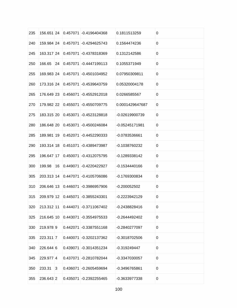
100
235 156.651 24 0.457071 -0.4196404368 0.1811513259 0
240 159.984 24 0.457071 -0.4294625743 0.1564474236 0
245 163.317 24 0.457071 -0.4378318369 0.1312142586 0
250 166.65 24 0.457071 -0.4447199113 0.1055371949 0
255 169.983 24 0.457071 -0.4501034952 0.07950309811 0
260 173.316 24 0.457071 -0.4539643759 0.05320004178 0
265 176.649 23 0.456071 -0.4552912018 0.0266585567 0
270 179.982 22 0.455071 -0.4550709775 0.0001429647687 0
275 183.315 20 0.453071 -0.4523128818 -0.02619900739 0
280 186.648 20 0.453071 -0.4500246084 -0.05245171981 0
285 189.981 19 0.452071 -0.4452290333 -0.0783536661 0
290 193.314 18 0.451071 -0.4389473987 -0.1038760232 0
295 196.647 17 0.450071 -0.4312075795 -0.1289338142 0
300 199.98 16 0.449071 -0.4220422927 -0.1534440166 0
305 203.313 14 0.447071 -0.4105706086 -0.1769300834 0
310 206.646 13 0.446071 -0.3986957906 -0.200052502 0
315 209.979 12 0.445071 -0.3855243301 -0.2223942129 0
320 213.312 11 0.444071 -0.3711067402 -0.2438828416 0
325 216.645 10 0.443071 -0.3554975533 -0.2644492402 0
330 219.978 9 0.442071 -0.3387551168 -0.2840277097 0
335 223.311 7 0.440071 -0.3202137362 -0.3018702506 0
340 226.644 6 0.439071 -0.3014351234 -0.319249447 0
345 229.977 4 0.437071 -0.2810782044 -0.3347030057 0
350 233.31 3 0.436071 -0.2605459694 -0.3496765861 0
355 236.643 2 0.435071 -0.2392255465 -0.3633977338 0
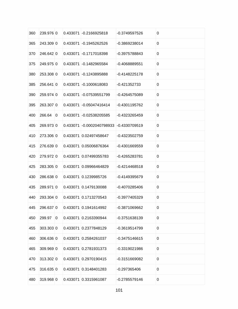
101
360 239.976 0 0.433071 -0.2166925818 -0.3749597526 0
365 243.309 0 0.433071 -0.1945262526 -0.3869238014 0
370 246.642 0 0.433071 -0.1717018398 -0.3975788843 0
375 249.975 0 0.433071 -0.1482965584 -0.4068889551 0
380 253.308 0 0.433071 -0.1243895888 -0.4148225178 0
385 256.641 0 0.433071 -0.1000618083 -0.421352733 0
390 259.974 0 0.433071 -0.07539551799 -0.4264575089 0
395 263.307 0 0.433071 -0.05047416414 -0.4301195762 0
400 266.64 0 0.433071 -0.02538205585 -0.4323265459 0
405 269.973 0 0.433071 -0.0002040798933 -0.4330709519 0
410 273.306 0 0.433071 0.02497458647 -0.4323502759 0
415 276.639 0 0.433071 0.05006876364 -0.4301669559 0
420 279.972 0 0.433071 0.07499355783 -0.4265283781 0
425 283.305 0 0.433071 0.09966464829 -0.4214468518 0
430 286.638 0 0.433071 0.1239985726 -0.4149395679 0
435 289.971 0 0.433071 0.1479130088 -0.4070285406 0
440 293.304 0 0.433071 0.1713270543 -0.3977405329 0
445 296.637 0 0.433071 0.1941614992 -0.3871069662 0
450 299.97 0 0.433071 0.2163390944 -0.3751638139 0
455 303.303 0 0.433071 0.2377848129 -0.3619514799 0
460 306.636 0 0.433071 0.2584261037 -0.3475146615 0
465 309.969 0 0.433071 0.2781931373 -0.3319021986 0
470 313.302 0 0.433071 0.2970190415 -0.3151669082 0
475 316.635 0 0.433071 0.3148401283 -0.297365406 0
480 319.968 0 0.433071 0.3315961087 -0.2785579146 0
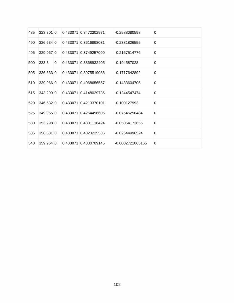
102
485 323.301 0 0.433071 0.3472302971 -0.2588080598 0
490 326.634 0 0.433071 0.3616898031 -0.2381826555 0
495 329.967 0 0.433071 0.3749257099 -0.2167514776 0
500 333.3 0 0.433071 0.3868932405 -0.194587028 0
505 336.633 0 0.433071 0.3975519086 -0.1717642892 0
510 339.966 0 0.433071 0.4068656557 -0.1483604705 0
515 343.299 0 0.433071 0.4148029736 -0.1244547474 0
520 346.632 0 0.433071 0.4213370101 -0.100127993 0
525 349.965 0 0.433071 0.4264456606 -0.07546250484 0
530 353.298 0 0.433071 0.4301116424 -0.05054172655 0
535 356.631 0 0.433071 0.4323225536 -0.02544996524 0
540 359.964 0 0.433071 0.4330709145 -0.0002721065165 0

103
Figure 45: Intake Design Plot (Initial)
Source: Own Elaboration
Figure 46: Intake Design Plot (Edited)
Source: Own Elaboration
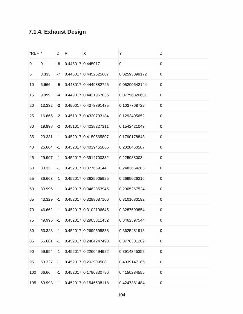
104
7.1.4. Exhaust Design
*REF * D R X Y Z
0 0 -8 0.445017 0.445017 0 0
5 3.333 -7 0.446017 0.4452625607 0.02593099172 0
10 6.666 -5 0.448017 0.4449882745 0.05200642144 0
15 9.999 -4 0.449017 0.4421967836 0.07796326601 0
20 13.332 -3 0.450017 0.4378891485 0.1037708722 0
25 16.665 -2 0.451017 0.4320733184 0.1293405652 0
30 19.998 -2 0.451017 0.4238227311 0.1542421049 0
35 23.331 -1 0.452017 0.4150565807 0.1790178848 0
40 26.664 -1 0.452017 0.4039465865 0.2028460587 0
45 29.997 -1 0.452017 0.3914700382 0.225988003 0
50 33.33 -1 0.452017 0.377669144 0.2483654283 0
55 36.663 -1 0.452017 0.3625905925 0.2699026316 0
60 39.996 -1 0.452017 0.3462853945 0.2905267524 0
65 43.329 -1 0.452017 0.3288087106 0.3101680192 0
70 46.662 -1 0.452017 0.3102196645 0.3287599854 0
75 49.995 -1 0.452017 0.2905811432 0.3462397544 0
80 53.328 -1 0.452017 0.2699595838 0.3625481918 0
85 56.661 -1 0.452017 0.2484247493 0.3776301262 0
90 59.994 -1 0.452017 0.2260494922 0.3914345352 0
95 63.327 -1 0.452017 0.202909508 0.4039147185 0
100 66.66 -1 0.452017 0.1790830796 0.4150284555 0
105 69.993 -1 0.452017 0.1546508118 0.4247381484 0
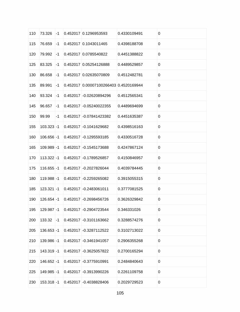
105
110 73.326 -1 0.452017 0.1296953593 0.4330109491 0
115 76.659 -1 0.452017 0.1043011465 0.4398188708 0
120 79.992 -1 0.452017 0.0785540822 0.4451388822 0
125 83.325 -1 0.452017 0.05254126888 0.4489529857 0
130 86.658 -1 0.452017 0.02635070809 0.4512482781 0
135 89.991 -1 0.452017 0.00007100266403 0.4520169944 0
140 93.324 -1 0.452017 -0.02620894296 0.4512565341 0
145 96.657 -1 0.452017 -0.05240022355 0.4489694699 0
150 99.99 -1 0.452017 -0.07841423382 0.4451635387 0
155 103.323 -1 0.452017 -0.1041629682 0.4398516163 0
160 106.656 -1 0.452017 -0.1295593185 0.4330516728 0
165 109.989 -1 0.452017 -0.1545173688 0.4247867124 0
170 113.322 -1 0.452017 -0.1789526857 0.4150846957 0
175 116.655 -1 0.452017 -0.2027826044 0.4039784445 0
180 119.988 -1 0.452017 -0.2259265082 0.3915055315 0
185 123.321 -1 0.452017 -0.2483061011 0.3777081525 0
190 126.654 -1 0.452017 -0.2698456726 0.3626329842 0
195 129.987 -1 0.452017 -0.2904723544 0.346331026 0
200 133.32 -1 0.452017 -0.3101163662 0.3288574276 0
205 136.653 -1 0.452017 -0.3287112522 0.3102713022 0
210 139.986 -1 0.452017 -0.3461941057 0.2906355268 0
215 143.319 -1 0.452017 -0.3625057822 0.2700165294 0
220 146.652 -1 0.452017 -0.3775910991 0.2484840643 0
225 149.985 -1 0.452017 -0.3913990226 0.2261109758 0
230 153.318 -1 0.452017 -0.4038828406 0.2029729523 0
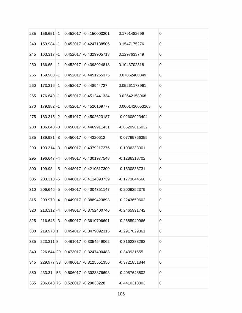
106
235 156.651 -1 0.452017 -0.4150003201 0.1791482699 0
240 159.984 -1 0.452017 -0.4247138506 0.1547175276 0
245 163.317 -1 0.452017 -0.4329905713 0.1297633749 0
250 166.65 -1 0.452017 -0.4398024818 0.1043702318 0
255 169.983 -1 0.452017 -0.4451265375 0.07862400349 0
260 173.316 -1 0.452017 -0.448944727 0.05261178961 0
265 176.649 -1 0.452017 -0.4512441334 0.02642158968 0
270 179.982 -1 0.452017 -0.4520169777 0.0001420053263 0
275 183.315 -2 0.451017 -0.4502623187 -0.02608023404 0
280 186.648 -3 0.450017 -0.4469911431 -0.05209816032 0
285 189.981 -3 0.450017 -0.44320612 -0.07799766355 0
290 193.314 -3 0.450017 -0.4379217275 -0.1036333001 0
295 196.647 -4 0.449017 -0.4301977548 -0.1286318702 0
300 199.98 -5 0.448017 -0.4210517309 -0.1530838731 0
305 203.313 -5 0.448017 -0.4114393739 -0.1773044666 0
310 206.646 -5 0.448017 -0.4004351147 -0.2009252379 0
315 209.979 -4 0.449017 -0.3889423893 -0.2243659602 0
320 213.312 -4 0.449017 -0.3752400746 -0.2465991742 0
325 216.645 -3 0.450017 -0.3610706691 -0.2685949966 0
330 219.978 1 0.454017 -0.3479092315 -0.2917029361 0
335 223.311 8 0.461017 -0.3354549062 -0.3162383282 0
340 226.644 20 0.473017 -0.3247400483 -0.343931655 0
345 229.977 33 0.486017 -0.3125551356 -0.3721851844 0
350 233.31 53 0.506017 -0.3023376693 -0.4057648802 0
355 236.643 75 0.528017 -0.29033228 -0.4410318803 0

107
360 239.976 105 0.558017 -0.2792109017 -0.4831399845 0
365 243.309 137 0.590017 -0.265023047 -0.5271459427 0
370 246.642 172 0.625017 -0.2478036368 -0.5737940466 0
375 249.975 203 0.656017 -0.2246399859 -0.616356375 0
380 253.308 226 0.679017 -0.1950318663 -0.6504049949 0
385 256.641 238 0.691017 -0.1596606805 -0.6723190919 0
390 259.974 242 0.695017 -0.1209990203 -0.6844032929 0
395 263.307 243 0.696017 -0.08112036203 -0.6912735719 0
400 266.64 242 0.695017 -0.0407345685 -0.6938222577 0
405 269.973 240 0.693017 -0.0003265765553 -0.6930169231 0
410 273.306 224 0.677017 0.03904260412 -0.6758902968 0
415 276.639 208 0.661017 0.07642235091 -0.6565844185 0
420 279.972 185 0.638017 0.1104834191 -0.6283781556 0
425 283.305 158 0.611017 0.1406161909 -0.5946165665 0
430 286.638 127 0.580017 0.1660727226 -0.5557333633 0
435 289.971 98 0.551017 0.1881968138 -0.5178819301 0
440 293.304 71 0.524017 0.2073061669 -0.4812670459 0
445 296.637 50 0.503017 0.225520838 -0.4496292405 0
450 299.97 31 0.484017 0.2417889894 -0.4192976758 0
455 303.303 14 0.467017 0.256423427 -0.3903228207 0
460 306.636 2 0.455017 0.2715219224 -0.3651250689 0
465 309.969 -7 0.446017 0.2865092987 -0.3418239109 0
470 313.302 -13 0.440017 0.3017829122 -0.3202218515 0
475 316.635 -17 0.436017 0.3169818533 -0.2993882579 0
480 319.968 -20 0.433017 0.3315547617 -0.2785231809 0
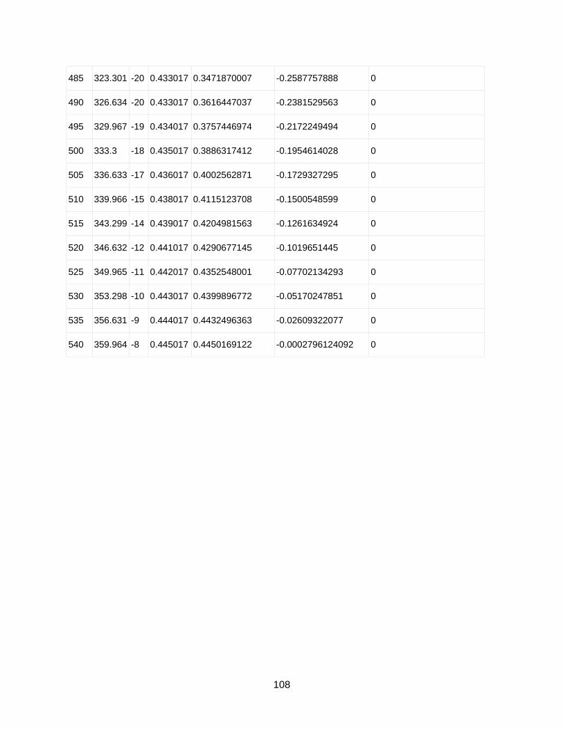
108
485 323.301 -20 0.433017 0.3471870007 -0.2587757888 0
490 326.634 -20 0.433017 0.3616447037 -0.2381529563 0
495 329.967 -19 0.434017 0.3757446974 -0.2172249494 0
500 333.3 -18 0.435017 0.3886317412 -0.1954614028 0
505 336.633 -17 0.436017 0.4002562871 -0.1729327295 0
510 339.966 -15 0.438017 0.4115123708 -0.1500548599 0
515 343.299 -14 0.439017 0.4204981563 -0.1261634924 0
520 346.632 -12 0.441017 0.4290677145 -0.1019651445 0
525 349.965 -11 0.442017 0.4352548001 -0.07702134293 0
530 353.298 -10 0.443017 0.4399896772 -0.05170247851 0
535 356.631 -9 0.444017 0.4432496363 -0.02609322077 0
540 359.964 -8 0.445017 0.4450169122 -0.0002796124092 0
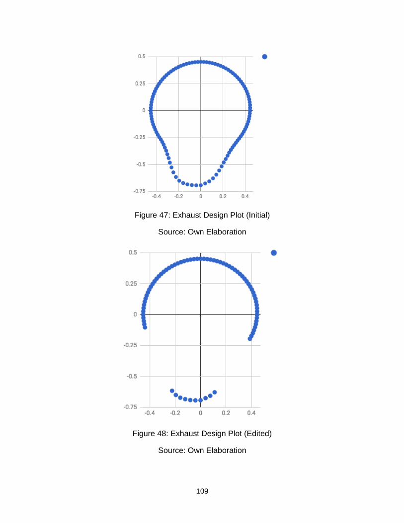
109
Figure 47: Exhaust Design Plot (Initial)
Source: Own Elaboration
Figure 48: Exhaust Design Plot (Edited)
Source: Own Elaboration
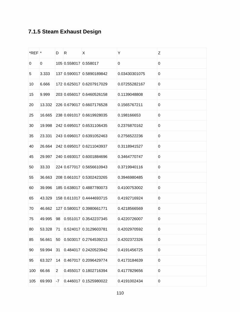
110
7.1.5 Steam Exhaust Design
*REF * D R X Y Z
0 0 105 0.558017 0.558017 0 0
5 3.333 137 0.590017 0.5890189842 0.03430301075 0
10 6.666 172 0.625017 0.6207917029 0.07255282167 0
15 9.999 203 0.656017 0.6460526158 0.1139048808 0
20 13.332 226 0.679017 0.6607176528 0.1565767211 0
25 16.665 238 0.691017 0.6619928035 0.198166653 0
30 19.998 242 0.695017 0.6531106435 0.2376870162 0
35 23.331 243 0.696017 0.6391052463 0.2756522236 0
40 26.664 242 0.695017 0.6211043937 0.3118941527 0
45 29.997 240 0.693017 0.6001884696 0.3464770747 0
50 33.33 224 0.677017 0.5656610943 0.3719940116 0
55 36.663 208 0.661017 0.5302423265 0.3946980485 0
60 39.996 185 0.638017 0.4887780073 0.4100753002 0
65 43.329 158 0.611017 0.4444693715 0.4192716924 0
70 46.662 127 0.580017 0.3980661771 0.4218566569 0
75 49.995 98 0.551017 0.3542237345 0.4220726007 0
80 53.328 71 0.524017 0.3129603781 0.4202970592 0
85 56.661 50 0.503017 0.2764539213 0.4202372326 0
90 59.994 31 0.484017 0.2420523942 0.4191456725 0
95 63.327 14 0.467017 0.2096429774 0.4173184639 0
100 66.66 2 0.455017 0.1802716394 0.4177829656 0
105 69.993 -7 0.446017 0.1525980022 0.4191002434 0
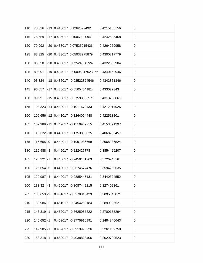
111
110 73.326 -13 0.440017 0.1262522492 0.4215155156 0
115 76.659 -17 0.436017 0.1006092094 0.4242506468 0
120 79.992 -20 0.433017 0.07525215426 0.4264279958 0
125 83.325 -20 0.433017 0.05033275879 0.4300817779 0
130 86.658 -20 0.433017 0.02524308724 0.4322805904 0
135 89.991 -19 0.434017 0.00006817523066 0.4340169946 0
140 93.324 -18 0.435017 -0.02522324546 0.4342851346 0
145 96.657 -17 0.436017 -0.05054541814 0.433077343 0
150 99.99 -15 0.438017 -0.07598556571 0.4313758061 0
155 103.323 -14 0.439017 -0.1011672433 0.4272014925 0
160 106.656 -12 0.441017 -0.1264064448 0.422513201 0
165 109.989 -11 0.442017 -0.1510989715 0.4153891297 0
170 113.322 -10 0.443017 -0.1753896025 0.4068200457 0
175 116.655 -9 0.444017 -0.1991936668 0.3968286524 0
180 119.988 -8 0.445017 -0.222427778 0.3854426207 0
185 123.321 -7 0.446017 -0.2450101263 0.372694516 0
190 126.654 -5 0.448017 -0.2674577476 0.3594239635 0
195 129.987 -4 0.449017 -0.2885445131 0.3440324552 0
200 133.32 -3 0.450017 -0.3087442215 0.327402361 0
205 136.653 -2 0.451017 -0.3279840423 0.3095848871 0
210 139.986 -2 0.451017 -0.3454282184 0.2899925521 0
215 143.319 -1 0.452017 -0.3625057822 0.2700165294 0
220 146.652 -1 0.452017 -0.3775910991 0.2484840643 0
225 149.985 -1 0.452017 -0.3913990226 0.2261109758 0
230 153.318 -1 0.452017 -0.4038828406 0.2029729523 0
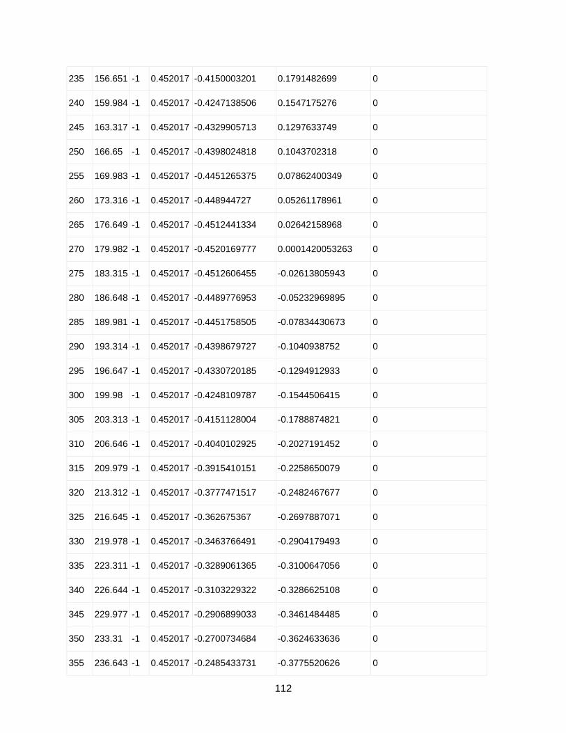
112
235 156.651 -1 0.452017 -0.4150003201 0.1791482699 0
240 159.984 -1 0.452017 -0.4247138506 0.1547175276 0
245 163.317 -1 0.452017 -0.4329905713 0.1297633749 0
250 166.65 -1 0.452017 -0.4398024818 0.1043702318 0
255 169.983 -1 0.452017 -0.4451265375 0.07862400349 0
260 173.316 -1 0.452017 -0.448944727 0.05261178961 0
265 176.649 -1 0.452017 -0.4512441334 0.02642158968 0
270 179.982 -1 0.452017 -0.4520169777 0.0001420053263 0
275 183.315 -1 0.452017 -0.4512606455 -0.02613805943 0
280 186.648 -1 0.452017 -0.4489776953 -0.05232969895 0
285 189.981 -1 0.452017 -0.4451758505 -0.07834430673 0
290 193.314 -1 0.452017 -0.4398679727 -0.1040938752 0
295 196.647 -1 0.452017 -0.4330720185 -0.1294912933 0
300 199.98 -1 0.452017 -0.4248109787 -0.1544506415 0
305 203.313 -1 0.452017 -0.4151128004 -0.1788874821 0
310 206.646 -1 0.452017 -0.4040102925 -0.2027191452 0
315 209.979 -1 0.452017 -0.3915410151 -0.2258650079 0
320 213.312 -1 0.452017 -0.3777471517 -0.2482467677 0
325 216.645 -1 0.452017 -0.362675367 -0.2697887071 0
330 219.978 -1 0.452017 -0.3463766491 -0.2904179493 0
335 223.311 -1 0.452017 -0.3289061365 -0.3100647056 0
340 226.644 -1 0.452017 -0.3103229322 -0.3286625108 0
345 229.977 -1 0.452017 -0.2906899033 -0.3461484485 0
350 233.31 -1 0.452017 -0.2700734684 -0.3624633636 0
355 236.643 -1 0.452017 -0.2485433731 -0.3775520626 0

113
360 239.976 -1 0.452017 -0.2261724538 -0.3913635004 0
365 243.309 -1 0.452017 -0.2030363915 -0.4038509527 0
370 246.642 -1 0.452017 -0.1792134558 -0.4149721744 0
375 249.975 -1 0.452017 -0.1547842396 -0.4246895424 0
380 253.308 -1 0.452017 -0.1298313873 -0.4329701828 0
385 256.641 -1 0.452017 -0.1044393145 -0.4397860819 0
390 259.974 -1 0.452017 -0.07869392283 -0.4451141818 0
395 263.307 -1 0.452017 -0.05268230903 -0.4489364572 0
400 266.64 -1 0.452017 -0.02649247061 -0.4512399775 0
405 269.973 -1 0.452017 -0.0002130079851 -0.4520169498 0
410 273.306 -1 0.452017 0.02606717525 -0.4512647456 0
415 276.639 -1 0.452017 0.05225917305 -0.4489859097 0
420 279.972 -1 0.452017 0.07827437771 -0.4451881513 0
425 283.305 -1 0.452017 0.1040247796 -0.4398843183 0
430 286.638 -1 0.452017 0.1294232649 -0.4330923536 0
435 289.971 -1 0.452017 0.1543839105 -0.4248352345 0
440 293.304 -1 0.452017 0.1788222742 -0.4151408948 0
445 296.637 -1 0.452017 0.2026556809 -0.4040421306 0
450 299.97 -1 0.452017 0.225803502 -0.3915764891 0
455 303.303 -2 0.451017 0.2476383617 -0.3769503629 0
460 306.636 -3 0.450017 0.2685382764 -0.3611128554 0
465 309.969 -3 0.450017 0.2890787909 -0.3448894793 0
470 313.302 -3 0.450017 0.3086413498 -0.3274993397 0
475 316.635 -4 0.449017 0.3264327786 -0.3083146239 0
480 319.968 -5 0.448017 0.3430400415 -0.2881714112 0

114
485 323.301 -5 0.448017 0.3592137918 -0.267739956 0
490 326.634 -5 0.448017 0.3741723194 -0.2464027348 0
495 329.967 -4 0.449017 0.3887307566 -0.2247324301 0
500 333.3 -4 0.449017 0.4011389407 -0.2017518688 0
505 336.633 -3 0.450017 0.4131080521 -0.1784853988 0
510 339.966 1 0.454017 0.4265442027 -0.1555361032 0
515 343.299 8 0.461017 0.4415701409 -0.1324857917 0
520 346.632 20 0.473017 0.4602006796 -0.1093636906 0
525 349.965 33 0.486017 0.4785816658 -0.08468833105 0
530 353.298 53 0.506017 0.5025591715 -0.05905491904 0
535 356.631 75 0.528017 0.527104465 -0.03102958705 0
540 359.964 105 0.558017 0.5580168899 -0.0003506123985 0
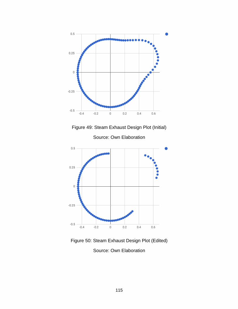
115
Figure 49: Steam Exhaust Design Plot (Initial)
Source: Own Elaboration
Figure 50: Steam Exhaust Design Plot (Edited)
Source: Own Elaboration

116
7.2 CAD Production Drawings
The following section contains the CAD production drawings for the whole
camshaft piece (shaft, cam lobes and assembly) and the timing gear. All four Drawings
came from CAD designed in SolidWorks®. Such drawings are drawn to scale, but scale
is not shown, as the size of each drawing in not defined. However, all dimensions are
numerically shown. Note that the drawings do not match the final pieces, they were initially
drawn to serve as a starting point and they do not take into account final modifications
such as the change in the number of teeth (from 57 to 30). Moreover, the lobes are also
indicative for timing and not cam lobe geometry.
7.2.1.a. Cam Assembly
7.2.1.b. Cam Base (lobes)
7.2.1.c. Shaft Base
7.2.2 Timing Gear
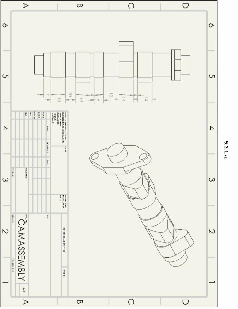
117
5.3
.1.a
.
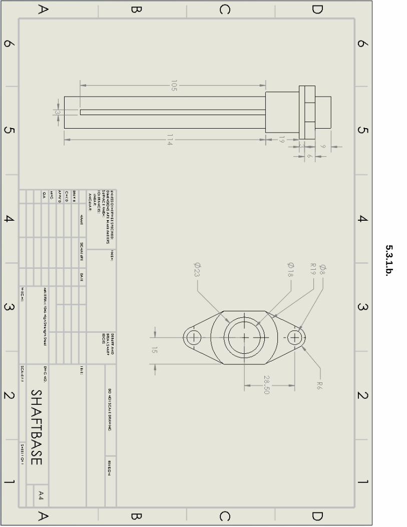
118
5.3
.1.b
.

119
5.3
.1.c
.
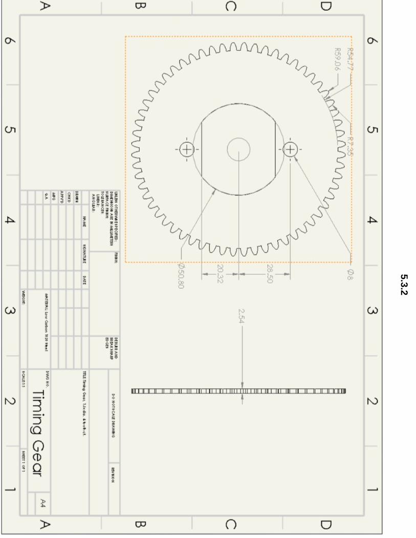
120
5.3
.2