Chinese Sulphur Dioxide Emissions and Local Environment Pollution
Upload
khangminh22Category
view
1download
0
A smarter perspective
© CIMAC 2019
Impact of Sulphur Cap 2020 on Two-Stroke Engine Tribology Aspects10 - Latest Engine Component Developments - Components & Tribology
Paper 437
Konrad Räss, WinGDDirector R&D
Samuel Affolter, WinGDSenior Manager Combustion Chamber
Roger Mäder, WinGDManager Tribology Fuel & Lubricants
Bartosz Rozmyslowicz, WinGDFuels & Lubricants Expert
Matthias Stark, WinGDResearch EngineerFuture Technologies
Markus F. Weber, WinGDSenior Development Engineer
ABSTRACT
The 2020 IMO 0.5 % sulphur cap for marine fuels will change the operating conditions for marinediesel engines. The uncertainty regarding the fuel portfolio after implementation of the new regulationraises concerns throughout the marine industry. Ship owners must decide whether they will invest inexhaust gas abatement technologies and still use high-sulphur fuels or change to 0.5 % sulphur fuels.However, independent of the scenario, the durability of combustion chamber components andlubrication system will not be affected. A state-of-the-art cylinder lubrication system combined withunique cylinder liner, piston and piston ring design allow long time between overhaul (TBO) forcombustion chamber components. Decades of knowledge operating with high-sulphur residual fuelstogether with profound experience in using low-sulphur fuels (obtained since first ECA enforcement in2005) allows a smooth transition for WinGD’s marine diesel engines in 2020 and beyond.
WinGD implemented a comprehensive lubricant validation program, which consisted of a laboratoryanalysis combined with extended field test performance assessments in close cooperation with thelubricant suppliers. The obtained vast number of validated cylinder oils with a broad spectrum of basenumbers (BN) are fit for operation with both low and high-sulphur fuels as well as gaseous fueloperation. Moreover, field experience regarding oil sampling, analysis and evaluation of the resultsprovides high confidence in setting the correct parameters for cylinder lubrication. This combined withstate-of-the-art chromium-ceramic piston rings and cylinder liner with a plateau-honed running surface,ensures reliable engine performance independent of the operating conditions.
Moving away from burning high-sulphur fuels in marine propulsion engines yields an opportunity todevelop novel technologies for both combustion chamber and lubricating system design. Decrease ofcorrosively induced cylinder liner wear allows for optimisation of cylinder liner cooling for demandingload-up procedures and fuels with different burning properties as those currently operating today.Furthermore, piston ring running surface properties might focus on targets other than corrosionresistance. This will give room for cost and TBO optimisation and more freedom in the choice of pistonring base material to comply with the requirements of future-oriented coating technologies. Cylinderlubrication systems might be optimised by new parameter settings for the extended residence time ofthe lubricant instead of aiming at constantly feeding fresh lubricant for acid neutralisation onto thecylinder liner running surface. Additionally, reduced additivation needed for acid neutralization incylinder lubricants is giving potential to focus on higher oxidation stability, deposit control and lubricityfor difficult operating conditions e.g. reduced light running margin or for effects of higher meaneffective pressure for future engines types. Finally, as a forerunner of technology development,WinGD is working on novel piston related technologies. This applies in particular, but not limited tonew piston ring base materials, coatings to achieve higher durability and wear resistance as well aspiston cooling, piston skirt centring techniques, cylinder liner cooling system for flexible temperaturecontrol and optimised lubricant supply systems.
The IMO 0.5 % fuel sulphur cap valid from 2020 is opening improvement potential for the already well-optimized engine designs. WinGD’s developments are directed to achieve best solutions for function,availability and cost for licensees, shipyards, operators and owners. This paper summarizes WinGD’scommitment to innovative solutions for engine design and parameter settings to fulfil the upcominglegislation and ship operator’s requirements ensuring trouble-free engine operation.
Powered by TCPDF (www.tcpdf.org)
CIMAC Congress 2019, Vancouver Paper No. 437 Page 3
1 INTRODUCTION
MARPOL Convention Annex VI regulates the air pollution being emitted by ships. One of the goals of this Annex was to reduce global emissions of Sulphur Oxides (SOX) by the marine industry. Therefore, the International Maritime Organization (IMO) introduced regulations limiting the sulphur content of marine fuels. In 2012, the sulphur content limit of 3.50 % for marine fuels came into force. On January 1st 2020, the new 0.50 % fuel sulphur limit will become effective.
This IMO 2020 fuel sulphur cap will obligate the introduction of new fuels in the market. Furthermore, it is foreseen that the HFO sulphur content distribution will become bimodal: with a split between IMO compliant very low sulphur fuel oil (VLSFO) ranging between 0.10-0.50 % sulphur content, and high sulphur fuel oil (HSFO) for scrubber operation with a sulphur content of up to 3.50 % or higher. The majority of the fuels which will be used in the market after January 1st 2020, will be VLSFO, as only a small percentage of vessels will be equipped with scrubbers [1], and therefore able to operate on HSFO. Depending on the origin and applied production processes, VLSFO may contain more paraffinic fractions compared to today’s residual fuels. Different levels of paraffinic and aromatic fractions within the fuels of the same ISO 8217:2017 grade could lead to incompatibility between different fuel batches. This problem will demand a higher level of fuel preparation and awareness about fuel compatibility. Additionally, due to different compositions, the fuels might have very different parameters (e.g. viscosity) within the same ISO grade.
Irrespective of sulphur content, viscosity and other properties, a fuel compliant with the ISO 8217:2017 specification will likely not impact negatively on the performance of Winterthur Gas & Diesel Ltd. (WinGD) engines as the design includes decades of operational experience using various fuel types with a wide range of sulphur contents and physical properties. This experience will ensure trouble-free operation with VLSFO into 2020 and beyond. Based on the status of engine development as given in [2], the tribology concept of WinGD engines has been further developed as will be described below. Since the first WinGD Dual-Fuel (DF) engines started to collect operational experience in 2016, it became apparent that the currently applied tribology concept is also suitable for operation with LNG as a fuel that contains virtually no sulphur.
Based on the reduction in fuel sulphur in compliance with the IMO 2020 fuel sulphur cap, and on the results of on-going technology
developments within WinGD, there exist opportunities for increased optimization to further reduce initial capital expenditure (CAPEX) and operating expenditure (OPEX) of WinGD marine two-stroke engines. These are described in proceeding sections below.
2 TRIBOLOGY CONCEPT FOR IMO 2020 AND BEYOND
2.1 Piston ring pack development
The three-piston-ring-concept for WinGD engines is described in detail in [3]. In summary, cast iron is a cost-efficient base material for large bore engine piston rings, because it is convenient to machine by turning and grinding. The Chrome Ceramic (CC) coating applied on top of the base material of the piston ring forms the running surface with a ground and lapped finish, and features a well-defined contact surface resistant to scuffing even in challenging operating conditions. Furthermore, it provides trouble-free running-in either in service on the vessel or at the engine manufacturer’s workshop. Finally, bespoke profiling of each piston ring’s running surface, based on its position in the ring pack, is used to optimise vertical lubricant transport on the cylinder liner. This design, well-tested in bench scale and field service for more than 10 years, has already proven itself not only with liquid fuels, but also with liquefied natural gas (LNG). LNG is considered a suitable low sulphur transition fuel until more sustainable alternatives to traditional fossil fuels are available.
No fundamental changes of the existing design or manufacturing processes of combustion chamber components are required in WinGD engines in order to use 2020 fuels. However, there remains inherent potential for ongoing optimisation which will improve other aspects of vessel lifecycle costs through improvements in capital expenditure, maintenance and overhaul costs, fuel and cylinder oil usage and potential out-of-service time, etc.
Due to the well-established, proven and excellent durability of the gas-tight top piston ring base material (vermicular cast iron = GGV) that has yielded no design-related piston ring fracture in service for over 10 years, it became apparent that two lower rings are now considered a costly and unnecessary redundancy and no longer needed for safety purposes. This is supported by the very low component wear rates experienced throughout the past decade, even in operation with HSFO. Therefore, the goal of recent development efforts was to incorporate the

CIMAC Congress 2019, Vancouver Paper No. 437 Page 4
function of the existing design elements into a piston head with two piston rings only.
The recently introduced two-piston-ring-concept for the WinGD X52 engine has the same sealing capability, vertical oil transport and ring stability as the three-piston-ring-pack, and still offers outstanding safety in the unlikely event of a top piston ring failure.
Type: GTP1CCxx
Coating thickness: ~0.35 mm
Barrel shape: Asymmetrical
Coating material: Chrome ceramic
Base material: GGV (vermicular graphite)
Type: SCP2CCxx
Coating thickness: ~0.15 mm
Barrel shape: Symmetrical
Coating material: Chrome ceramic
Base material: GG spec. III (lamellae graphite)
Type: SCP2CCxx
Coating thickness: ~0.15 mm
Barrel shape: Asymmetrical
Coating material: Chrome ceramic
Base material: GG spec. III (lamellae graphite)
Figure 1: Development of piston ring pack from three piston rings to two piston rings
This design offers, due to the reduced number of piston rings and corresponding ring grooves, lifecycle cost-savings in CAPEX and OPEX which includes a reduction in maintenance costs for piston head remanufacturing. Furthermore, the amount of lubricant loss is reduced due to the piston ring pack optimisation. In combination with cylinder oil accumulating grooves on the cylinder liner, designed to expand the piston ring pack pressure before the scavenge air ports, piston ring pack spray through the scavenge air ports and associated lubrication losses are reduced. The two-piston-ring-concept therefore offers outstanding lubrication performance at lowest cost. The trouble-free operation of the first X52 and X52DF engines confirms this optimized tribology concept and the success of the development strategy of WinGD.
The introduction of the 0.50 % sulphur cap will translate into new opportunities for piston ring base material and coating developments since the expected reduced demands for corrosion resistance will allow for an optimisation to more cost-effective production as well as required wear resistance.
A large focus in optimising lifetime performance of large two stroke marine diesel engines combines maximizing reliability and improving the utilization of the lubricant simultaneously. The latter, being the key driver for recent piston ring pack developments, aims at reducing cylinder lubricant
losses while maintaining or enhancing lubrication performance. The main aspects considered include lubricant transportation and distribution characteristics that are achieved by implementing a new piston ring pack design, as well as piston ring profiles with dedicated functionalities.
The following part of the paper describes efforts in this regard, and provides insight into WinGD’s technology advancement approach comprising simulation tool development and validation, design of experiments and the related validation approach based on complex rig testing and measurement technology applications, as well as a full-scale engine testing to provide the desired results. More details can be found in [4].
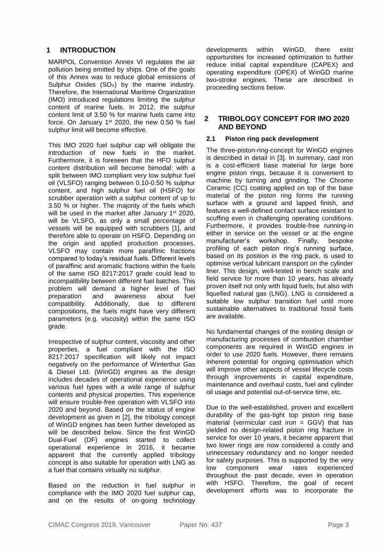
A characterisation of different contributors to the cylinder oil balance of an engine is important when aiming to enhance lubrication performance and reduce its contribution to exhaust gas emissions. It is essential to quantify relevant parameters helping to estimate lubrication losses referring to present lubrication regimes of the engine. Possible contributors to the total cylinder oil consumption are shown in Figure 2.
Describing the lubricant balance of a marine two-stroke engines concentrates on the determination of:
• Lubricant property-related evaporation effects
• Piston ring pack dynamics
• Valve stem lubrication
• Turbocharger lubrication
• The formation of lubricant property-related
deposits
• Piston underside losses
• Leakage (e.g. Piston rod stuffing box)
In order to quantify and validate improvements
and modifications to the tribology concept,
cylinder lubricant fate and transport was assessed
via real-time acquisition of SO2 concentration
variations in the exhaust gas originating from the
fuel and lubricant. SO2 was used as a tracer for
the lubricant in the exhaust gas as it is associated
to sulphur contents of fuel and lubricant.
CIMAC Congress 2019, Vancouver Paper No. 437 Page 5
Evaporation
Piston Ring pack
Valve stemlubrication
Turbochargerlubrication
Lubrication impact on exhaust gas
Deposits
Lubrication losses
Deposits
Piston undersidelosses
Leakage
Lube Oil Balance
Figure 2: Schematic of a typical 2 stroke diesel engine cylinder oil balance
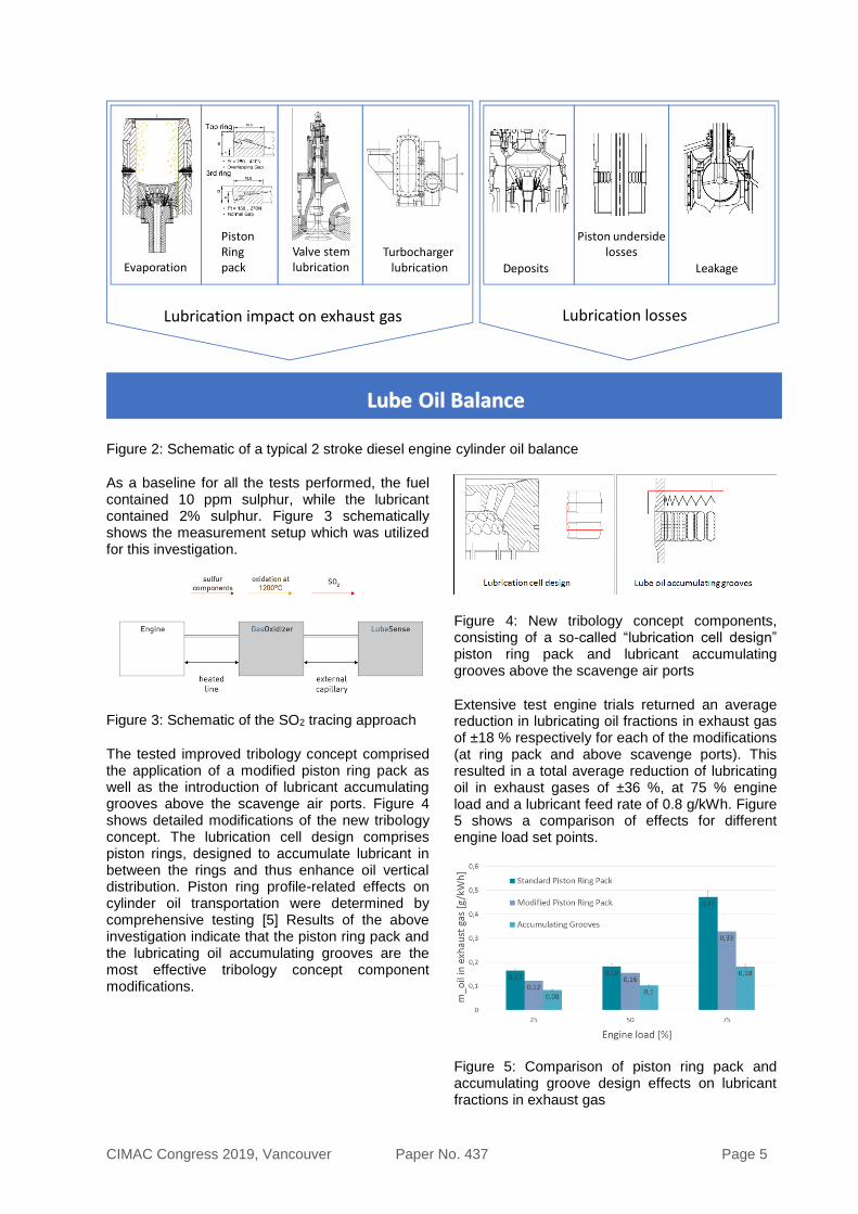
As a baseline for all the tests performed, the fuel contained 10 ppm sulphur, while the lubricant contained 2% sulphur. Figure 3 schematically shows the measurement setup which was utilized for this investigation.
Figure 3: Schematic of the SO2 tracing approach
The tested improved tribology concept comprised the application of a modified piston ring pack as well as the introduction of lubricant accumulating grooves above the scavenge air ports. Figure 4 shows detailed modifications of the new tribology concept. The lubrication cell design comprises piston rings, designed to accumulate lubricant in between the rings and thus enhance oil vertical distribution. Piston ring profile-related effects on cylinder oil transportation were determined by comprehensive testing [5] Results of the above investigation indicate that the piston ring pack and the lubricating oil accumulating grooves are the most effective tribology concept component modifications.
Figure 4: New tribology concept components, consisting of a so-called “lubrication cell design” piston ring pack and lubricant accumulating grooves above the scavenge air ports
Extensive test engine trials returned an average reduction in lubricating oil fractions in exhaust gas of ±18 % respectively for each of the modifications (at ring pack and above scavenge ports). This resulted in a total average reduction of lubricating oil in exhaust gases of ±36 %, at 75 % engine load and a lubricant feed rate of 0.8 g/kWh. Figure 5 shows a comparison of effects for different engine load set points.
Figure 5: Comparison of piston ring pack and accumulating groove design effects on lubricant fractions in exhaust gas
CIMAC Congress 2019, Vancouver Paper No. 437 Page 6
Testing the modified engine components of the enhanced tribology concept provided interesting insights into dynamic tribology effects and a quantification of system-related contributions to overall lubricant consumption. As demonstrated, application of a modified piston ring pack and cylinder oil accumulating grooves can significantly reduce lubricant fractions in the exhaust gas and shows superior functionality in terms of controlling the lubricant film build up [4]. However, results of this investigation also demonstrated further optimization potential with regard to lubrication system development as explained below.
2.2 Lubrication system development
Overall, WinGD research and advancements in the lubrication system have led to a significant increase in lubricant utilisation (increase in efficacy) and a simultaneous significant reduction of lubricant fractions in exhaust gases (increase in efficiency).
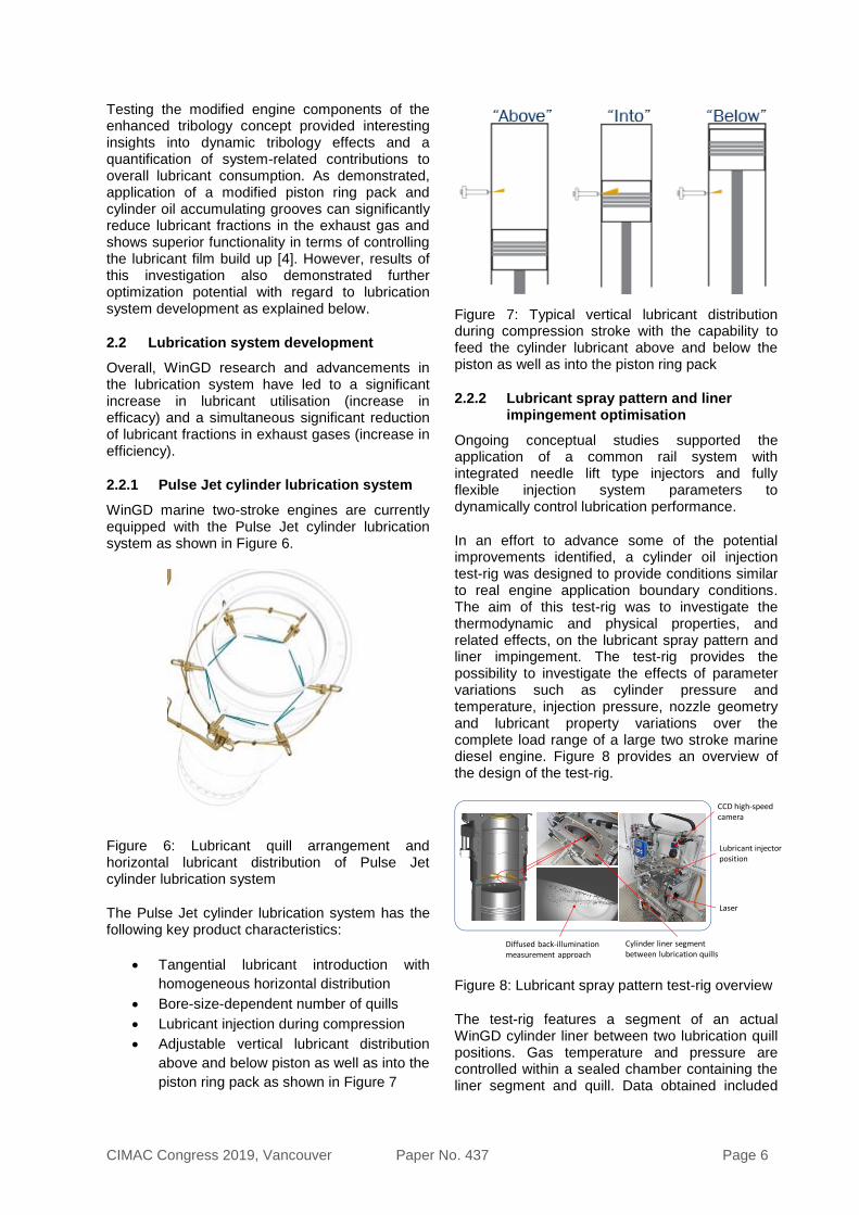
2.2.1 Pulse Jet cylinder lubrication system
WinGD marine two-stroke engines are currently equipped with the Pulse Jet cylinder lubrication system as shown in Figure 6.
Figure 6: Lubricant quill arrangement and horizontal lubricant distribution of Pulse Jet cylinder lubrication system
The Pulse Jet cylinder lubrication system has the following key product characteristics:
• Tangential lubricant introduction with
homogeneous horizontal distribution
• Bore-size-dependent number of quills
• Lubricant injection during compression
• Adjustable vertical lubricant distribution
above and below piston as well as into the
piston ring pack as shown in Figure 7
Figure 7: Typical vertical lubricant distribution during compression stroke with the capability to feed the cylinder lubricant above and below the piston as well as into the piston ring pack
2.2.2 Lubricant spray pattern and liner impingement optimisation
Ongoing conceptual studies supported the application of a common rail system with integrated needle lift type injectors and fully flexible injection system parameters to dynamically control lubrication performance.
In an effort to advance some of the potential improvements identified, a cylinder oil injection test-rig was designed to provide conditions similar to real engine application boundary conditions. The aim of this test-rig was to investigate the thermodynamic and physical properties, and related effects, on the lubricant spray pattern and liner impingement. The test-rig provides the possibility to investigate the effects of parameter variations such as cylinder pressure and temperature, injection pressure, nozzle geometry and lubricant property variations over the complete load range of a large two stroke marine diesel engine. Figure 8 provides an overview of the design of the test-rig.
CCD high-speedcamera
Lubricant injectorposition
Laser
Cylinder liner segmentbetween lubrication quills
Diffused back-illumination measurement approach
Figure 8: Lubricant spray pattern test-rig overview
The test-rig features a segment of an actual WinGD cylinder liner between two lubrication quill positions. Gas temperature and pressure are controlled within a sealed chamber containing the liner segment and quill. Data obtained included

CIMAC Congress 2019, Vancouver Paper No. 437 Page 7
high-resolution and ultra-high frame-rate optical information, which was used in the analyses.
Figure 9 shows time-comparable video frame-shots of typical lubricant spray patterns at different simulated engine load conditions using a standard two-hole nozzle geometry with a common cylinder oil injector.
Figure 9: Typical spray investigation results of different simulated engine load conditions for a) 10 %, b) 50 % and c) 100 % simulated engine load conditions and related spray breakup regimes
A solid spray pattern was found to maximize the momentum of the lubricant during cylinder admission. The appearance of the spray breakup at higher engine load consequently leads to the conclusion that atomization of the lubricant spray must be prevented to optimize lubrication performance by reducing the amount of lubricant in the exhaust gas. Thus, the need to control lubrication system parameters, such as injection pressure and timing, justified the development of a new and fully flexible lubrication system.
Furthermore, the additional environmental benefit of reduced cylinder oil related emissions to the atmosphere, caused by oil atomisation, cannot be overlooked.
2.2.3 Testing of optimised spray pattern and in-cylinder distribution
The final step in lubrication system development culminated in a full-scale engine application and related performance testing. The volume of injected lubricant oil was kept constant between the new and the existing lubrication systems. However, the shape and impingement of the lubricant spray in the new system was varied by adjusting injection pressure and timing.
Figure 10 shows the setup installed on the RTX-6 test engine.
Figure 10: Final installation of the new lubrication system prototype
A direct comparison between the standard lubrication system with the new common rail type lubrication system was realized by testing at two different lubrication levels on the same cylinder liner. However, comparing different lubrication systems must be performed on the same injection level to compensate for evaporation effects and to isolate specific lubrication system related effects on the exhaust gas composition. Therefore, both lubrication systems were tested at both injection levels respectively and thus provided comparable results and performance data.
Figure 11 shows two quill levels which provided firstly a comparison between the new and existing lubrication systems, and secondly an insight into the influence of the injection level itself on cylinder oil consumption.
Figure 11: Test setup for a parallel lubrication system comparison

CIMAC Congress 2019, Vancouver Paper No. 437 Page 8
Figure 12 shows measurement results of the new common rail type lubrication system for different engine load set points.
Figure 12: Common rail type lubrication system cylinder oil consumption comparison between different engine load set points
Both lubrication system measurement results demonstrated a similar relationship between engine load and evaporation – measured by the effects on exhaust gas composition. The question remained as to how much of the evaporated lubricant was due to thermal effects and how much was due to an uncontrolled lubricant spray breakup of a common lubrication system. Comparing different engine load cases for both lubrication systems as in Figure 13 shows the difference between lubrication system performances and leads to the conclusion that under similar engine load conditions, the additional amount of lubricant in the exhaust gas must be spray pattern related.
Figure 13: Comparison between lubrication systems at different engine loads and 0.8 g/kWh cylinder oil feed rate
Figure 14 gives an overview on investigated tribology concept component modifications and related effects alone and in combination on the potential for lubricant fractions in exhaust gases.
Figure 14: Overview of decreasing lubricant fractions in exhaust gas at 75 % engine load and 0.8 g/kWh lubricant feed rate
These engine trials clearly demonstrated that the new lubrication system performance exceeded expectations and demonstrated that these modifications, aimed at controlling the lubricant spray, are very important when attempting to reduce overall lubricant losses.
However, further opportunities for advancements have been identified which include improving nozzle geometry as well as an overall design review leading to a more compact, simplified and retrofittable design.
2.3 Cylinder liner running surface
The liner running surface is machined by different degrees of turning and a subsequent step of honing, followed by plateau finishing through brushing. These three manufacturing steps have been optimised in the past years to achieve the required surface roughness with shorter machining time and tailored tools for cost-effective production of cylinder liners.
The state of the art, as in other industries such as the automotive manufacturing business, still applies: newly produced liners are machined with a running surface comparable to one that has already been in operation for thousands of hours. This process ensures trouble-free running-in both at the engine manufacturer’s workshop and in service aboard vessel.
It is therefore not expected that the IMO 2020 sulphur cap will require a cylinder liner machining change since it works well with LNG and fuels from zero to 3.50 % sulphur...
2.4 Combustion chamber cooling system
Cylinder cooling systems of WinGD 2-stroke engines were designed to achieve liner wall temperatures above the dew point of water to prevent cold corrosion of the cylinder liner surface by condensation of sulphuric acid. Maximum
CIMAC Congress 2019, Vancouver Paper No. 437 Page 9
cylinder liner surface temperatures are limited by allowable thermal stresses for the given cylinder liner and piston ring material plus the thermal stability of the applied lubricant.
The original liner cooling system is designed cost-effectively with a single coolant stream with constant flow rate over the entire load range. The intended cooling system outlet temperature is achieved by varying the cooling water inlet temperature by an adjustable three-way-valve. As this system is laid out for the heat flow at rated engine power, it was not capable of maintaining a constantly high liner wall temperature at lower engine loads. Therefore, the risk of cold corrosion of the cylinder liner surface at very low loads could not be excluded.
To improve the behaviour at low engine loads, WinGD has introduced an optimized cooling system with the X-engine generation. It features a bypass line around the cooler to feed a fraction of the coolant water flow directly back to the cylinder liner at outlet temperature level. This has resulted in locally higher liner wall temperatures compared to the traditional system, while maintaining a constant coolant flow and outlet temperature target value over the entire load range.
While the development of X-DF engines was progressing, it became apparent that, depending on the fuel in use, different and if not contradicting functions needed to be fulfilled by the cylinder liner cooling system. In liquid fuel mode, the use of sulphur-containing fuels requires high liner wall temperature to prevent cold corrosion. In gas fuel mode, the premixed combustion regime yields best performance when combustion chamber component surfaces are held at a lower temperature.
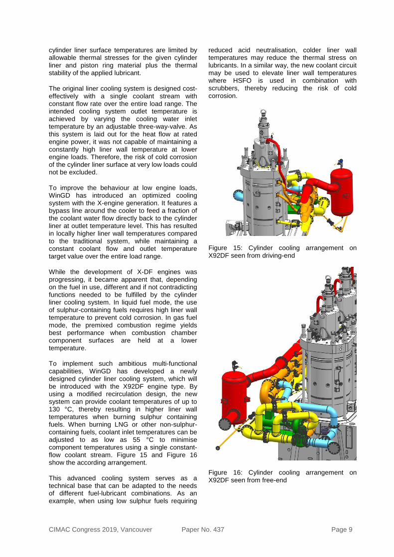
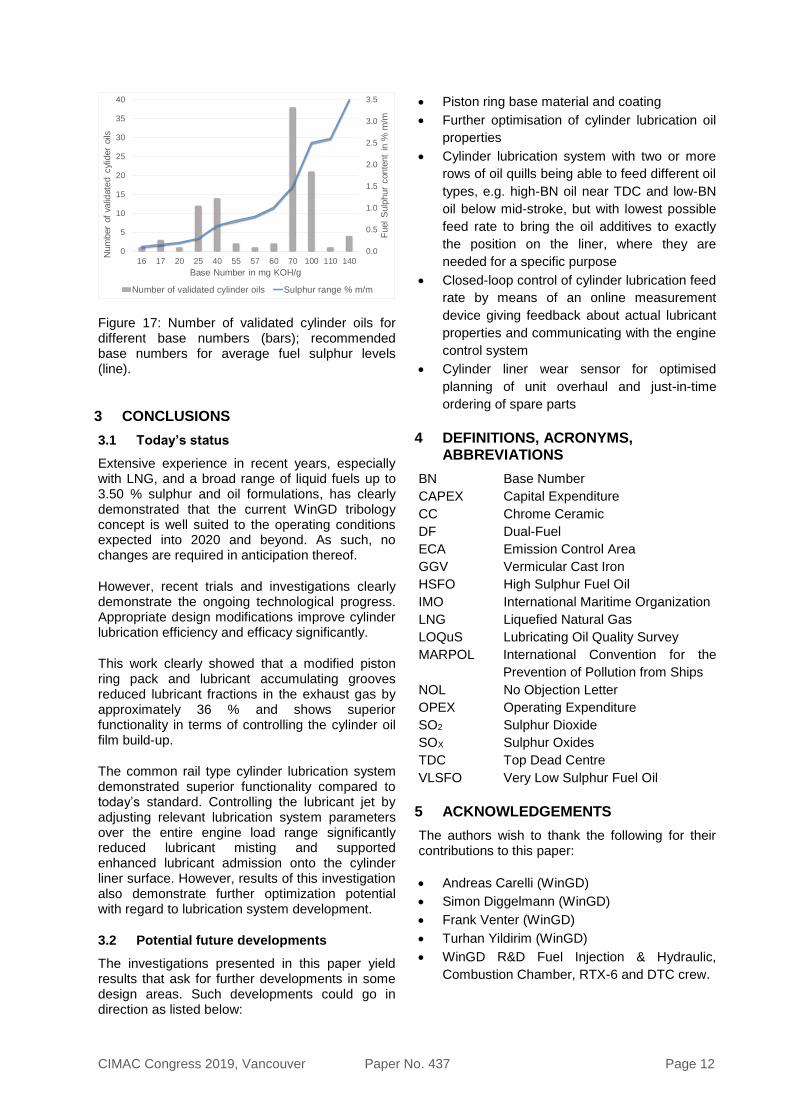
To implement such ambitious multi-functional capabilities, WinGD has developed a newly designed cylinder liner cooling system, which will be introduced with the X92DF engine type. By using a modified recirculation design, the new system can provide coolant temperatures of up to 130 °C, thereby resulting in higher liner wall temperatures when burning sulphur containing fuels. When burning LNG or other non-sulphur-containing fuels, coolant inlet temperatures can be adjusted to as low as 55 °C to minimise component temperatures using a single constant-flow coolant stream. Figure 15 and Figure 16 show the according arrangement.
This advanced cooling system serves as a technical base that can be adapted to the needs of different fuel-lubricant combinations. As an example, when using low sulphur fuels requiring
reduced acid neutralisation, colder liner wall temperatures may reduce the thermal stress on lubricants. In a similar way, the new coolant circuit may be used to elevate liner wall temperatures where HSFO is used in combination with scrubbers, thereby reducing the risk of cold corrosion.
Figure 15: Cylinder cooling arrangement on X92DF seen from driving-end
Figure 16: Cylinder cooling arrangement on X92DF seen from free-end

CIMAC Congress 2019, Vancouver Paper No. 437 Page 10
2.5 Lubricants for post 2020 fuels
The cylinder lubricant oil is a vital design element of the two-stroke marine engine. The main roles of the cylinder lubricant are to lubricate and seal the piston ring-cylinder liner interface, protect metal surfaces against corrosion and clean the combustion chamber components.
Due to the formerly pervasive high sulphur content in marine fuels and the subsequent problems with cylinder liner corrosion [6], cylinder lubricants are still predominately identified by their base number (BN) as an indication of their acid neutralisation capacity. However, due to MARPOL regulations, the base number of cylinder lubricant oils in use will become bimodal split between very low BN and high BN lubricant oils. Low BN oils will be used for globally compliant <0.50 % S fuels, ECA zone compliant <0.10 % S fuels and for LNG / gas operation. High BN oils will predominantly be used for engines equipped with scrubbers that choose to use high sulphur content fuels up to 3.50 % sulphur.
As mentioned above the current portfolio of high BN oils will be used mainly for scrubber operation. There will be no significant change in the formulation approach for these oils as the base number will remain the most important parameter. Depending on the sulphur content of the fuels, oils with BN 70, BN 100 or, the newly introduced BN 140 lubricant will be used. The appearance of BN 140 oils on the market is considered important as there will be no fuel sulphur content limit for ships fitted with emissions abatement scrubber technology.
It is assumed that in future the majority of the ships will use low-sulphur fuel and therefore base number distribution in the market will shift towards lower BN values. The lower base additive content of low BN lubricants is simultaneously an opportunity and a challenge for oil and engine development: newly formulated oils have to sustain the same performance as the high BN oils, especially when using low sulphur residual fuels. However, this is also an opportunity to focus oil development on other lubricant properties which may have been at a lower priority in previous years.
Besides actual physical lubrication and corrosion protection via acid neutralisation, the most important parameter of the cylinder oil is its ability to maintain the lowest possible deposit formation on the piston. Due to decrease of the sulphur content in the majority of the fuels to 0.5 %, low BN oils (instead of high BN oils) will also be used for residual fuels. However, low BN lubricating oils were initially designed for distillate fuels which
have different characteristics to residual fuels. The lower purity of residual fuels has an impact on combustion chamber cleanliness. Therefore, lubricating oils require new formulations before January 2020 to reach an appropriate performance level.
The important properties for post 2020 lubricants such as detergency and dispersancy need to be adjusted for the requirements of these novel, low sulphur containing residual fuels. Oils with a high amount of detergent are able to prevent and simultaneously gradually remove the deposits formed on the piston. Deposit prevention and removal is important as its excessive formation on the piston top land and in the ring pack can lead to abrasive liner wear or ring seizure followed by scuffing. Previously, due to the chemical nature of the added alkaline components, detergency has correlated well with BN number, however after 1 January 2020 this may not always be the case as certain oils may require additional detergency in the absence of the acid neutralisation components.
Another important property for oil performance is dispersancy. While detergents are used to remove deposits from combustion chamber components, dispersants play a role in keeping impurities suspended in the oil to aid in their transport through to the piston underside drain. Additionally, dispersants may also assist in preventing agglomeration of impurities, including soot and asphaltene particles, which could result in increased deposit formation.
Additionally, the deposit formation is influenced by the stability of the lubricant on the cylinder liner wall. One cause of deposit formation can be oil decomposition caused by severe thermal conditions in the combustion chamber. The decomposition of the oil leads not only to deposit formation, but physical lubricating properties and the ability to maintain additive chemical efficacy in the oil might also be influenced negatively. Cylinder oil average residence time on the cylinder wall is assumed to be in the order of magnitude of minutes. During this period, the oil has to maintain its properties despite the oxidative conditions at high temperature. Oxidation stability can be influenced by base oil selection and also by the quantity of chemicals with antioxidative properties in the additives package. Oxidative stability is an important oil property to consider for the future as the conditions in the combustion chamber might become increasingly severe due to the constant drive to improve the efficiency of the engine.

CIMAC Congress 2019, Vancouver Paper No. 437 Page 11
Furthermore, higher oxidation stability of lubricants is needed for DF engines. Due to premixing of fuel gas with air in the combustion chamber, combustion occurs closer to the cylinder liner. Therefore, during combustion the oil is exposed to higher thermal stress than in the diesel cycle. Because LNG is an environmentally and economically beneficial fuel, and is one of the solutions for MARPOL 2020, lubricant development must additionally consider this.
2.6 Validation procedure
WinGD has a comprehensive lubricant validation program, which has been fine-tuned over many years based on the experience from previous validations. The program has been adjusted frequently to align it with the continuous further development of our engines and to comply with the changes in the lubricant market.
Overall the validation of a candidate cylinder lubricant oil consists of three main steps:
1. Extensive laboratory analysis of the oil
2. Field trial of the oil in an approved WinGD engine
3. Review and decision in collaboration with the applicant.
Oil validation reviews and decisions also consider the varying lubricant formulations and applications when reviewing laboratory and field data. The formulation details including the additive package, additive ratio change, base oil type or thickener type, all play a role in the selection of the correct validation procedure and in the interpretation of results. Different intended applications such as operation on gaseous fuels, high BN lubricants in ECA areas or blending on board require specific test procedures to assess the performance of the lubricant for its intended use.
2.6.1 Laboratory Analysis
WinGD has named this process ‘LOQuS’ (Lubricating Oil Quality Survey). Prior to the field trail, the candidate oil is subjected to a broad spectrum of laboratory tests ranging from basic chemical analyses to the performance behaviour on rig tests tuned for specific oil characteristics. These include, among others, the determination of deposit formation potential and thermo-oxidative stability.
If the oil passes the LOQuS screening process, a “Letter of Support” is issued to the oil company which may be used when seeking agreements
with vessel owners for extended field testing of the candidate oil.
2.6.2 Field Testing
WinGD works closely with the applicant oil company during the extended field test to ensure optimal performance and fair adjudgment of the oil.
Most of the field trial validations start with an overhaul of the chosen test cylinder to avoid influences from previous operating conditions. Depending on the oil formulation, there are different test duration requirements specified: either 2’000 or 4’000 running hours. Frequent component inspections and drain oil monitoring during the entire test duration are required to obtain a comprehensive overview of the lubricant performance in the field. At the end of every field trial, the test cylinder is overhauled again for a detailed inspection and taking of measurements on the wear components.
2.6.3 Review and Decision
The information from the applicant, compiled data from the laboratory analysis and the field test are reviewed and allow WinGD to judge the performance and suitability of the lubricant. After a successful validation, WinGD issues a so called “No Objection Letter” (NOL), which is valid for two years and the lubricant will be included on a list of validated lubricants. After the initial two-year validity has expired, as long as the lubricants are performing well in service, WinGD re-issues the NOL upon application. Alternatively, the oil will be removed from the list of validated lubricants.
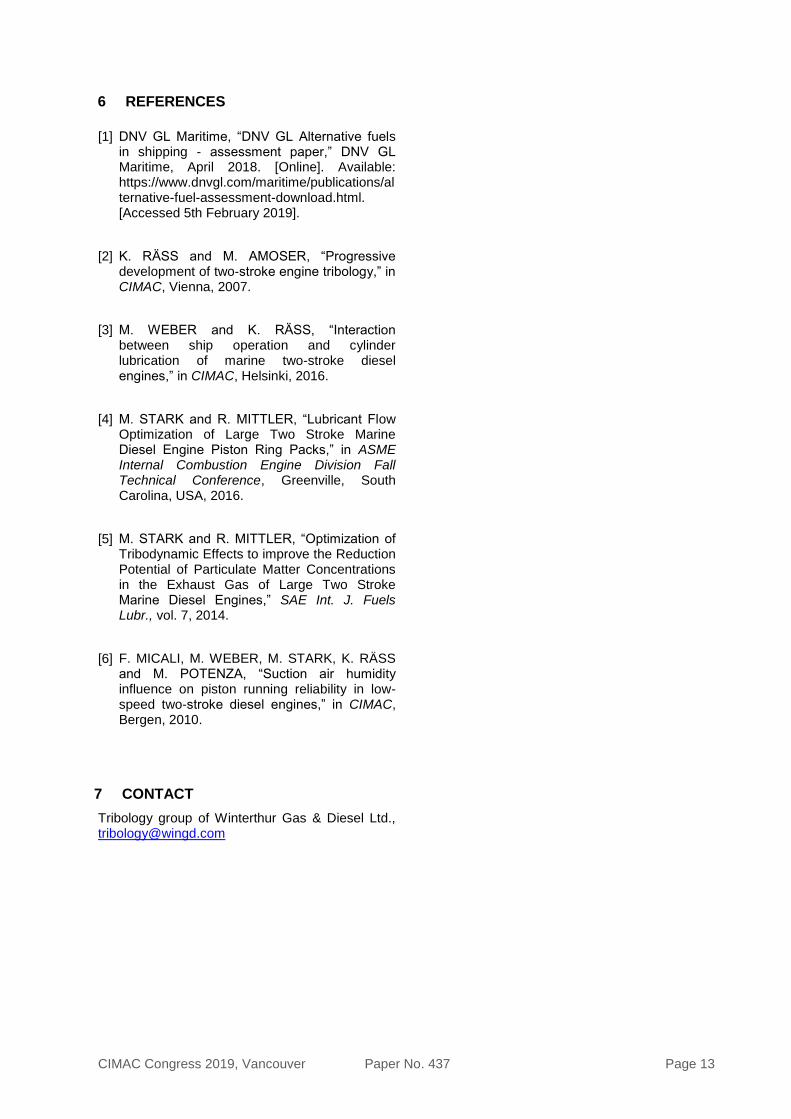
There currently exists a large number of WinGD validated cylinder oils with a broad spectrum of properties such as base numbers (BN) which are fit for operation with both low and high-sulphur fuels as well as for gaseous fuel operation (Figure 17). Due to the robust validation procedure, WinGD is confident that, independent on type, quality or sulphur content, the current lubricant portfolio is suited to the latest engine designs and will ensure a smooth transition to new fuels in 2020.
WinGD is in close contact with all relevant lubricant suppliers to be up to date concerning oil developments in general and as well to exchange information regarding the 2020 sulphur cap. The feedback received from the lubricant suppliers about tests with 0.50 % sulphur fuels on WinGD engines confirms that currently no issues have been flagged: either with combustion or lubrication systems and processes.
CIMAC Congress 2019, Vancouver Paper No. 437 Page 12
0.0
0.5
1.0
1.5
2.0
2.5
3.0
3.5
0
5
10
15
20
25
30
35
40
16 17 20 25 40 55 57 60 70 100 110 140
Fuel
Sulp
hur
conte
nt
in %
m/m
Num
ber
of
valid
ate
d c
ylid
er
oils
Base Number in mg KOH/g
Number of validated cylinder oils Sulphur range % m/m
Figure 17: Number of validated cylinder oils for different base numbers (bars); recommended base numbers for average fuel sulphur levels (line).
3 CONCLUSIONS
3.1 Today’s status
Extensive experience in recent years, especially with LNG, and a broad range of liquid fuels up to 3.50 % sulphur and oil formulations, has clearly demonstrated that the current WinGD tribology concept is well suited to the operating conditions expected into 2020 and beyond. As such, no changes are required in anticipation thereof.
However, recent trials and investigations clearly demonstrate the ongoing technological progress. Appropriate design modifications improve cylinder lubrication efficiency and efficacy significantly.
This work clearly showed that a modified piston ring pack and lubricant accumulating grooves reduced lubricant fractions in the exhaust gas by approximately 36 % and shows superior functionality in terms of controlling the cylinder oil film build-up.
The common rail type cylinder lubrication system demonstrated superior functionality compared to today’s standard. Controlling the lubricant jet by adjusting relevant lubrication system parameters over the entire engine load range significantly reduced lubricant misting and supported enhanced lubricant admission onto the cylinder liner surface. However, results of this investigation also demonstrate further optimization potential with regard to lubrication system development.
3.2 Potential future developments
The investigations presented in this paper yield results that ask for further developments in some design areas. Such developments could go in direction as listed below:
• Piston ring base material and coating
• Further optimisation of cylinder lubrication oil
properties
• Cylinder lubrication system with two or more
rows of oil quills being able to feed different oil
types, e.g. high-BN oil near TDC and low-BN
oil below mid-stroke, but with lowest possible
feed rate to bring the oil additives to exactly
the position on the liner, where they are
needed for a specific purpose
• Closed-loop control of cylinder lubrication feed
rate by means of an online measurement
device giving feedback about actual lubricant
properties and communicating with the engine
control system
• Cylinder liner wear sensor for optimised
planning of unit overhaul and just-in-time
ordering of spare parts
4 DEFINITIONS, ACRONYMS, ABBREVIATIONS
BN Base Number
CAPEX Capital Expenditure
CC Chrome Ceramic
DF Dual-Fuel
ECA Emission Control Area
GGV Vermicular Cast Iron
HSFO High Sulphur Fuel Oil
IMO International Maritime Organization
LNG Liquefied Natural Gas
LOQuS Lubricating Oil Quality Survey
MARPOL International Convention for the
Prevention of Pollution from Ships
NOL No Objection Letter
OPEX Operating Expenditure
SO2 Sulphur Dioxide
SOX Sulphur Oxides
TDC Top Dead Centre
VLSFO Very Low Sulphur Fuel Oil
5 ACKNOWLEDGEMENTS
The authors wish to thank the following for their contributions to this paper:
• Andreas Carelli (WinGD)
• Simon Diggelmann (WinGD)
• Frank Venter (WinGD)
• Turhan Yildirim (WinGD)
• WinGD R&D Fuel Injection & Hydraulic,
Combustion Chamber, RTX-6 and DTC crew.
CIMAC Congress 2019, Vancouver Paper No. 437 Page 13
6 REFERENCES
[1] DNV GL Maritime, “DNV GL Alternative fuels in shipping - assessment paper,” DNV GL Maritime, April 2018. [Online]. Available: https://www.dnvgl.com/maritime/publications/alternative-fuel-assessment-download.html. [Accessed 5th February 2019].
[2] K. RÄSS and M. AMOSER, “Progressive development of two-stroke engine tribology,” in CIMAC, Vienna, 2007.
[3] M. WEBER and K. RÄSS, “Interaction between ship operation and cylinder lubrication of marine two-stroke diesel engines,” in CIMAC, Helsinki, 2016.
[4] M. STARK and R. MITTLER, “Lubricant Flow Optimization of Large Two Stroke Marine Diesel Engine Piston Ring Packs,” in ASME Internal Combustion Engine Division Fall Technical Conference, Greenville, South Carolina, USA, 2016.
[5] M. STARK and R. MITTLER, “Optimization of Tribodynamic Effects to improve the Reduction Potential of Particulate Matter Concentrations in the Exhaust Gas of Large Two Stroke Marine Diesel Engines,” SAE Int. J. Fuels Lubr., vol. 7, 2014.
[6] F. MICALI, M. WEBER, M. STARK, K. RÄSS and M. POTENZA, “Suction air humidity influence on piston running reliability in low-speed two-stroke diesel engines,” in CIMAC, Bergen, 2010.
7 CONTACT
Tribology group of Winterthur Gas & Diesel Ltd., [email protected]
Powered by TCPDF (www.tcpdf.org)

This paper has been presented and published at the 29th CIMAC World Congress 2019 in Vancouver,Canada. The CIMAC Congress is held every three years, each time in a different member country. The Congress program centres around the presentation of Technical Papers on engine research and development, application engineering on the original equipment side and engine operation and maintenance on the end-user side. The themes of the 2019 event included Digitalization & Connectivity for different applications, System Integration, Electrification & Hybridization, Emission Reduction Technologies, Low Carbon Combustion including Global Sulphur Cap 2020, Case Studies from Operators, Product Development of Gas and Diesel Engines, Components & Tribology, Turbochargers, Controls & Automation, Fuels & Lubricants as well as Basic Research & Advanced Engineering. The copyright of this paper is with CIMAC. For further information please visit https://www.cimac.com.
Copyright © 2022 FDOKUMEN