- CAP! - World Radio History
64
-
Upload
khangminh22 -
Category
Documents
-
view
0 -
download
0
Transcript of - CAP! - World Radio History
AUGUST 1986
COMMUNICATIONS ENGINEERING AND DESIGN THE MAGAZINE OF BROADBAND TECHNOLOGY
Fiberoptics move into the future
Cable outages can be controlled!
LAN buyers: where have they gone?
- CAP! FREQUENCY CHART
›****************3-DIGIT 565 CED000208204 01 ### FRED MCCORMACK 533 HASTAD ENGINEERING
HALSTAD MN 56548

-
TM
FROM MAGNAVOX First and Mil the best
When you needed a high-per-formance technology, we developed PowerDoubling. Your enthusiastic response has made PowerDoubling so successful others have tried to copy it. But they can't match our equipment's performance.
PowerDoubling from Magnavox provides twice the power output so you can use more gain without sacri-ficing quality. Since PowerDoubling has the highest compression poiQt . of any hybrid, you can also increase reach.
More bandwidth lets you offer customers more choice, including 550/600 MHz. And our bypass option ensures signal reliability.
All this performance is cost effec-tive too:
• Often no need to change trunk spacings or move amplifiers.
II A high-efficiency switch-mode power supply to save on power bills.
• Compatible with most existing systems, so you can upgrade economically.
la As easy to install and maintain as our conventional amplifiers.
Find out about PowerDoubling from Magnavox. Because the first is still the best. Ask your Magnavox account executive, or call toll-free 800-448-5171 (in NY State 800-522-7464; Telex 937329).
Magnavox CAN Systems, Inc. A North American Philips Company
100 Fairgrounds Drive Manlius NY 13104
•e-- • •
Reader Service Number 1
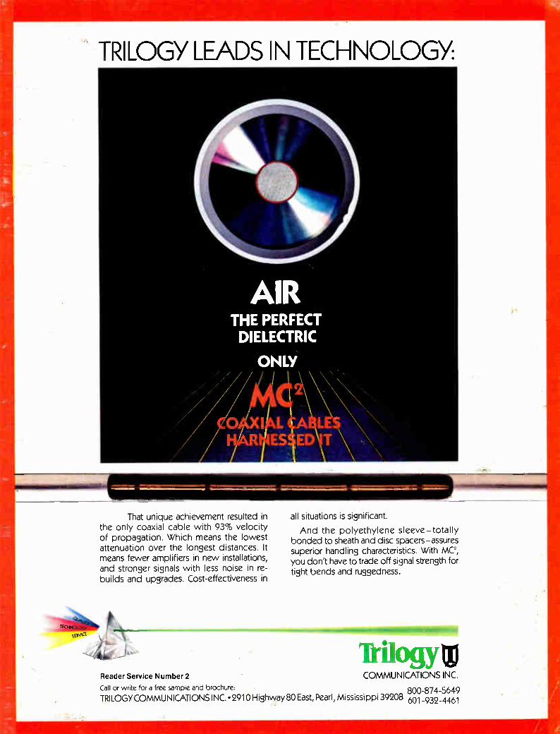
TRILOGY LEADS IN TECHNOLOGY:
1==111M1M11=11:3 That unique achievement resulted in
the only coaxial cable with 93% velocity of propagation. Which means the lowest attenuation over the longest distances. It means fewer amplifiers in new installations, and stronger signals with less noise in re-builds and upgrades. Cost-effectiveness in
11111illb ssexe
all situations is significant.
And the polyethylene sleeve—totally bonded to sheath and disc spacers—assures superior handling characteristics. With MC', you don't have to trade off signal strength for tight bends and ruggedness.
milogY0 Reader Service Number 2 COMMUNICATIONS INC. Call or write for a free sample and brochure: 800-874-5649 TRILOGY COMMUNICATIONS INC. • 2910 Highway 80 East, Pearl, Mississippi 39208 601-932-4461
•Mil

CED August 1986 Volume 12, Number 8
EDITORIAL Gary Y. Kim Publisher/Editor Kathy Berlin Associate Publisher Linda J. Johnson Production Editor Roger Brown Technical Writer Derrick Jackson Editorial Assistant
CONSULTING ENGINEERS Chairman Wendell H. Bailey, NCTA VP, Science and Technology
Members Jim Chiddix, Senior VP, Eng., Oceanic Cablevision (ATC). Ron Cotten, VP of Engineering. Daniels & Associates Bob Dattner, VP, Technical Services, Media General Cable John Dawson, VP of Engineering, Mile Hi Cablevision Roy Ehman, VP of Engineering, Storer Cable Communications Mark Elden, Director of Engineering, Showtime/The Movie Channel Robert Lutl, Senior VP. Engineering, United Artists Cablesystems Steve Raimondi, Director of Eng. (East), United Artists Cablesystems Graham Stubbs, VP, Science and Technology, Oak Communications Sruki Switzer, Consulting Engineer Joe Van Loan, Eng. VP, Viacom Cablevision
PRODUCTION Jetf Knight, Production Director Don Ruth, Art Director Diane Krensky, CED Art Director Debra Rensel, Typography. Traffic Greg Packer, Circulation Director
ADVERTISING Cathy Wilson, Sales Manager Christina Panczyk, Classified Sales Lesley Camino, Promotions
Patrick Keleher, President/CEO David Carlton, Vice President, Financial & Administration Janice L. Benesch, Controller
OFFICES Denver 600 Grant Street, Suite 600, Denver, CO 80203 -or- P.O. Box 5208 TA., Denver, CO 80217, (303) 860-0111. Washington Bureau 1625 I Street, Suite 615, Washington, D.C. 20006, (202) 835-0900. New York Bureau 432 Park Avenue South, Suite 1109, New York, N.Y. 10016, (212) 213-3110.
ITCI INTERNATIONAL THOMSON COMMUNICATIONS INC.
1986 by International Thomson Commu-nications Inc. All rights reserved. CED. IUSPS 300-5101 IISSN 0191-5428lis pub-lished monthly by International Thomson Communications Inc., 600 Grant St., Den-ver, CO 80203. August 1986, Volume 13. Number 8. Subscriptions free to qualified industry readers. All other one-year sub-scriptions are $26. prepaid in U.S. funds only. Second-class postage paid at Denver, CO. CED is published on behalf of the cable television and broadband communications industries. POSTMASTER: Please send address changes to P.O. Box 5208 T.A., Denver, Colorado 80217. MEMBERS OF THE BPA.
SPOTLIGHT
Meeting the challenge Hawaii's special cable needs has led Jim Chiddix to some innovative methods of servicing Oceanic's customers.
8
MY TURN
Going beyond the dBs Engineers need to expand themselves beyond the decibel and the dollar bill.
12
CLASSICS
Trap requirements A 20-foot drop is an effective means of testing a trap's stability.
16
Outage control tips Here's some down-to-earth tips on controlling cable outages.
34
SPECIAL FEATURE
CATV frequency chart Here is the most updated and comprehensive CATV Frequency Chart for 1986.
37
Moving ahead The future will see fiber optics being used in local, campus and municipal network markets.
56
LAN buyer shortage LANs may be a good buy, but try finding a buyer.
58
Fiberoptic design system Fiberoptics is moving into a new environment of application.
PRODUCT PROFILES
Standby power supplies 74
DEPARTMENTS
In Perspective 14 Classifieds 80 Ad Index 82 In the News 83
About the cover New methods of preventing cable outages —many caused by lightning—are being tried by operators. Photo used courtesy of William P. Winn, Langmuir Laboratories of the New Mexico Institute of Mining and Technology.
66
4 Communications Engineering and Design August 1986

POWER COMPANY INTO LOWER' YOUR BILL 10%.
For example, the Super Ferro is 93% efficient at normal load factor (see graph at richt). Take that news to your power cormany, and you've cot a powerful argument for a 10% saving in your power bill. T. SUPER FERRO EFFICIENCY VS. TYPICAL FERRO
VVe've wt together test results to help you prove the increased efficiency of the Super Ferro to even the most skeptical utilly company.
Call 1-800-551-3790 or write today for complete details and test results. Because that 10% would look better on your bottom line than on your power line.
E Intro-ducing the first superferroresonant power sup-ply-the new Lectro Super Ferro.
It's a radical improvement in NG power supply technology. It oper-
ates 10% more efficiently than most power supplies available until now.
954/
90
85
; 8705
70
65
60
55
50
MIIMIIIMMIIMIIIMIllionnw•—•-MIZIIIIIIIIIIIIIIP"'"-- UPER FERRO TYPICAL FERRO
....1.11" "
Mine
Ur I
Alia11.1111.1113.111.11111
/1113113M111•111•111111111•11111
111111111N1 11111M1
2 3 4 5 6 7 8 9 10 11 12 , CluiPUT CURREeg AMPEPFS
Super Ferro Outperforms The Average Power Supply At Every Load Factor
THE NEW eJr SUPER FERRO
BY LEM° Reader Service Number 3
A Burnup & Sims Cable Products Group Company

I NTRODUCIlle 111/ABC011115 LITT" If you install dropwire you're going to scream with delight when you see M/A-COM's new Multidrop bundles. They're perfect for apartments, condos, schools, hospitals, anywhere one dropwire just won't do.
Leave them flat to run along baseboards, up walls or down elevator shafts. Roll them up to fit through cracks and corners and conduit. Or, bunch several together to go in a dozen different directions at once. Either way, they make multiple dropwire installations quicker and easier than ever before. Multidrop bundles are available in all common dropwire sizes, and, with a little advance
notice and a big order, we can deliver these babies in any configuration you're likely to need.

i NIULTIDROR E BUNDLE OF JOY.
So, if you think dropwire bundles are an idea long past due, see your M/A-COM Comm/Scope representative or call 1-800-982-1708.
Multidrop. The birth of something big.
Comun/scope PO Box 1729, Hickory, NC 28603, 800-982-1708, in NC 800-222-6808, telex: 802-166
Reader Service Number 4

spotlight
Jim Chiddix
New technology essential to Chiddix
Experimenting with new technolo-gies in order to bring his subscribers improved service has always been a high priority to Jim Chiddix, senior vice president of Oceanic Cablevision Inc. in Honolulu, Hawaii. But it's going to be even more important over the next decade, he says, to find ways to deliver service cost effectively to counteract the threat posed by alterna-tive delivery systems. Because of Hawaii's remote location
and difficult terrain, cable systems there have often started at a disadvan-tage. Consequently, it was there that some of the early tests with satellite signal delivery, stand-alone pay televi-sion, pay-per-view and now, fiberop-tics, have taken place.
"It was a fairly innovative place, but more out of desperation than out of cleverness," says Chiddix when dis-cussing the Oceanic system of 10 years ago. Because the system had little to offer people who already had good off-air reception, Oceanic had to look for ways to set itself apart. Therefore, it was an early player in pay TV, satel-lite-delivered programming and ad-dressability. For Chiddix, a native Pennsyl-
vanian, it was a trip to Hawaii during
his senior year at Cornell, where he was studying electrical engineering, that resulted in his permanent relocation to the island state. "I fell in love with the islands" im-
mediately, says the 40-year-old Chid-dix, who found work as a crewman on a charter sailboat. "That was a great way to get to know Hawaii but I rap-idly found that I had to get a job that actually paid money." He then stum-bled upon Cablevision Inc., a small ru-ral lease-back system owned by the telephone company and located near the boat harbor.
"I began by repairing headend equipment and rental TV sets and no-body else could do that," Chiddix says. So he became the system's technical manager. After the FCC ordered the telcos to
divest themselves of all lease-back sys-tems, Chiddix moved into the manage-ment of the system. "I suddenly found myself general manager," he recalls. After successfully rolling out pay
television, Chiddix turned his efforts to designing and manufacturing video-tape automation equipment. These de-vices provided automated playback of pay TV signals and automated tape de-lay of satellite feeds, which was made necessary by the number of time zones between Hawaii and the mainland. The company that he founded, CRC Elec-tronics, later made commercial inser-tion equipment, providing cable sys-tems with another source of revenue. By 1978, Chiddix became engineer-
ing vice president for Oceanic Cablevi-sion, a system which at that time had about 30,000 subscribers. After over-seeing the installation of one of the first earth stations in Hawaii, Chiddix rolled out pay TV services and in-vested in addressability through an early Oak system. With the advent of addressability, Oceanic was able to ex-plore pay-per-view and added tiers of pay services.
In 1981, Oceanic was acquired by ATC and a steady growth period en-sued. Oceanic, through acquisition and construction, has grown to be the sev-enth largest system in the country, with about 170,000 subscribers. But operating the system had its
challenges. In order to improve ser-vice, Oceanic reconfigured its micro-wave delivery system, built FM video
trunks, experimented with data trans-mission and now offers nine pay ser-vices plus PPV.
In recognition of his efforts to pro-vide Hawaii with the latest technologi-cal advantages, the NCTA awarded Chiddix with its Engineering Award for Outstanding Achievement in Oper-ations in 1984. But he hasn't stopped there. In
1984, Oceanic acquired a system on the windward side of Oahu that provided a huge technical challenge to Chiddix. Because the headend was located on
one side of the mountains and the sub-scribers were on the other side, the sys-tem offered poor quality signals and had severe power problems. Because no acceptable microwave
path was available, Chiddix oversaw the installation of a long-haul passive fiberoptic system that brings high quality signals 14 miles through the mountains.
"It was an absolutely fascinating project," recalls Chiddix. And because he could find little information on the subject, Chiddix has since presented papers to the NCTA concerning the application of fiber to cable systems. And although he is impressed by fi-ber's capabilities, Chiddix says it should be considered to be just another tool to be used to deliver quality sig-nals.
In spite of cable's rapid growth over the last several years, Chiddix says he sees the next decade as the most chal-lenging times for the industry. "My biggest concern is our being in
a position to compete effectively with what seems to be an inevitable and fairly effective competition from DBS. We are going to be competing with a service that is inherently more reliable and capable of better quality than our long cascades of cable equipment. And when that day comes, it's very impor-tant that we have our product mix set, be consumer friendly, responsive to consumer needs and have our costs under control so we can be price com-petitive," says Chiddix.
In the meantime, cable subscribers in Honolulu can rest assured that they will be on the receiving end of some of the most recent technological ad-vances in the industry. Jim Chiddix will see to that.
—Roger Brown
8 Communications Engineering and Design August 1986
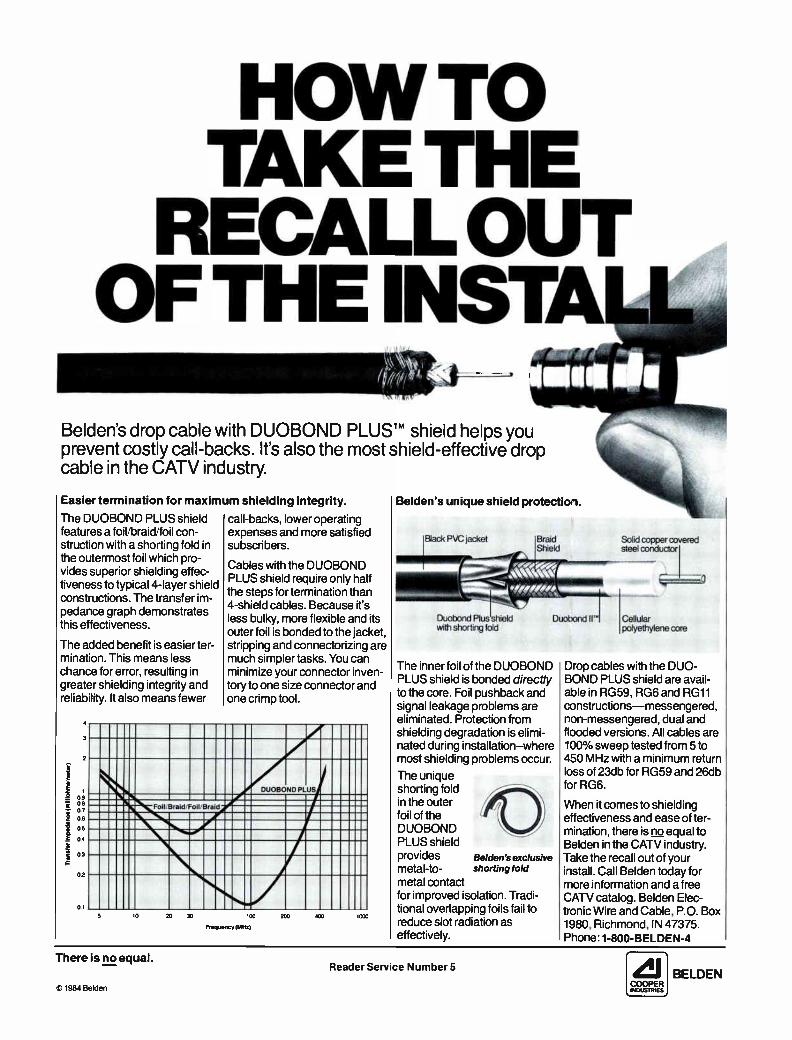
HOW TO TAKE THE
RECALL OUT OF THE INSTA
Belden's drop cable with DUOBOND PLUSTM shield helps you prevent costly call-backs. It's also the most shield-effective drop cable in the CATV industry.
Easier termination for maximum shielding integrity.
The DUOBOND PLUS shield features a foil/braid/foil con-struction with a shorting fold in the outermost foil which pro-vides superior shielding effec-tiveness to typical 4-layer shield constructions. The transfer im-pedance graph demonstrates this effectiveness.
The added benefit is easier ter-mination. This means less chance for error, resulting in greater shielding integrity and reliability. It also means fewer
Treeeter In Went. (mellohme meter)
4
3
2
1 09 08 0.7 06
05
04
0.3
0.2
call-backs, lower operating expenses and more satisfied subscribers.
Cables with the DUOBOND PLUS shield require only half the steps for termination than 4-shield cables. Because it's less bulky, more flexible and its outer foil is bonded to the jacket, stripping and connectorizing are much simpler tasks. You can minimize your connector inven-tory to one size connector and one crimp tool.
DUOBOND PLUS
Foll/Brald/FoIPBrald
10 20 30 100
Frequency (MHz)
200 400 1000
Belden's unique shield protection.
The inner foil of the DUOBOND PLUS shield is bonded directly to the core. Foil pushback and signal leakage problems are eliminated. Protection from shielding degradation is elimi-nated during installation—where most shielding problems occur.
The unique shorting fold in the outer foil of the DUOBOND PLUS shield provides metal-to- shorting fold
metal contact for improved isolation. Tradi-tional overlapping foils fail to reduce slot radiation as effectively.
Belden's exclusive
Drop cables with the DUO-BOND PLUS shield are avail-able in RG59, RG6 and RG11 constructions—messengered, non-messengered, dual and flooded versions. All cables are 100% sweep tested from 5 to 450 MHz with a minimum return loss of 23db for RG59 and 26db for RG6.
When it comes to shielding effectiveness and ease of ter-mination, there is no equal to Belden in the CATV industry. Take the recall out of your install. Call Belden today for more information and a free CATV catalog. Belden Elec-tronic Wire and Cable, P.O. Box 1980, Richmond, IN 47375. Phone: 1-800-BELDEN-4
There is no equal.
:t 1984 Belden
Reader Service Number 5 BELDEN

Carson's GLB-1320... a great cover up
for tap and coax splice locations!
• Great for housing of under-ground tap and drop locations. • Use with Channell's UTH-500 and -700 series enclosures and KCP-500, -1500 and -2000 splice connector series. • Structural foam molded of HDPE. • Boxes are pre-assembled and lightweight. • Tapered to eliminate upheaval and provide stability. • CATV identification molded into
cover. • 100% stainless steel hex head
bolt or penta head security bolt provided. • Available through distribution:
Anixter Cable TV Supply Signal Vision
Marketed exclusively by Channell Commercial Corporation
(818) 963-1694 (800) 423-1863
except in CA
CARSON INDUSTRIES INC. 1925 "A" Street La Verne, CA 91750
my turn
Expand your goals beyond the dBs Forty years ago, I met an interesting
young man, age 17, a senior in high school; bright, activist, a sort of angry young man who wanted the world to change its ways, day after tomorrow at the latest. George Jackson had a couple of
problems. He was blind, but not from birth; at an early age, he suffered a se-rious illness that left his eyes atro-phied and useless. Had good medical care been available to him, his eyes could probably have been protected and saved, even in the early '30s. But he had another problem: he is
black, and medical care was not avail-able. So George was blind when I met him. The difference between courage and
foolhardiness is sometimes hard to de-fine. George was brave; brave beyond
Archer S. Taylor, Senior Vice President, Engineering, Malarkey-Taylor Associates Inc.
all reason. One day, on a dare, stone blind, he rode a bicycle for three blocks through the heavy traffic of cars, trol-leys, buses and trucks on Bloomfield Avenue in urban New Jersey. He made it, but admits he was scared stiff. George never uses a white cane, and
accepts the arm of a guide most reluc-tantly. Next door to our home, close to the sidewalk, was the stump of an old birch tree, about three feet high. I warned George about the possibility of miscounting the trees and making a wrong turn. To say that he was in-sulted would be a gross understate-ment. He never touches the trees; he just counts them as he goes past, and he would certainly not be fooled by a stump. As an angry young man, with the
courage and determination to do what he saw needed to be done, George con-templated violence to protest the ram-pant discrimination he saw all around him. (Blind though he is, he sees plenty). Cooler heads prevailed, and the violence did not happen. After graduating from high school,
George entered Seton Hall, a catholic college in Newark. He tells me he was kicked out, probably for his unceasing activism and protest. Then I lost track of him. Last January, nearly 40 years later,
I saw him on national TV. Dr. George Jackson, PhD, professor of social ser-vices at Howard University in Wash-ington, was being interviewed by Bill Moyer during that disturbing CBS documentary on teen pregnancy. George is now a mature, 57-year old
professor. His violent dreams are long past; but his active determination to stand up and be counted persists. He was one of two candidates for provost at Antioch College, but lost out when he answered the president's question by saying he would actively support student efforts to pursuade the college to disinvest in South Africa. Engineers and technicians should
have goals and interests beyond the dB's, whether that means decibels or dollar bills. We need to be inspired once in a while by the courage and de-termination of the George Jacksons of this world, BA,MA, PhD. Who knows? Perhaps our own handi-
caps may be our golden opportunities.
Reader Service Number 6
12 Communications Engineering and Design August 1986

Only RMS guarantees -120 dB RFI in its CA-1090/M and CA-2090/M directional couplers, and CA-2002/SM silver plated two-way hybrid splitter. No one else comes close.
These products are especially useful at the headend, in systems in metropolitan areas, and in LAN systems where RF integrity is essential.
RMS ELECTRONICS, INC. 50 Antin Place, Bronx, N.Y., 10462
CALL COLLECT: (212) 892-1000 (New York State) TOLL FREE: (800) 223-8312 (Continental U.S.A., Puerto Rico, U.S. Virgin Islands)

in perspective
IS-15 is rolling Although not everybody in CATV
will welcome the decision, the NCTA Engineering Committee has voted to endorse the EIA's proposed baseband interface standard IS-15. The EIA it-self already supports the interim stan-dard, which might be adopted on more than an interim basis in a year or so. An NCTA subcommittee has been set up to work for widespread industry adoption of the standard, which could, in 10 years or so, dramatically lower the cost of addressability and open the door for subscriber ownership of home CATV terminals. In essence, IS-15 proposes a universal TV interface that would, among other things, reduce the cost of scrambling, since it takes the tuner, IF sound demodulator and mod-ulator out of set-top converters. The plug would return all tuning
functions to the cable-compatible TV, lower operator capital investment in the home, and open the door to much more rugged signal security at a much lower cost. The interface would operate at baseband, not IF. And there's the rub, for some people. Although work on the baseband interface has been proceeding for quite some time, there's been some opinion that the interface really ought to operate at IF, taking advantage of the industry's current preference for RF, rather than base-band, scrambling techniques. Debate has been vigorous on this is-
sue, for all kinds of reasons. As is al-ways the case, standards aren't vendor neutral. Any given standard can help or harm the business interests of par-ticular parties. The debate over IS-15 was no exception. Some decoder manu-facturers favored the IF version of the interface; others the baseband. Still others wanted both. The arguments in favor of RF went something like this: 75 percent of existing CATV systems that are scrambling are doing so at RF, not baseband. Current sales, as well as the installed base, reflect that ratio. An IF interface would be backwards compatible; not so with the baseband version. Also, from a converter manu-facturer's perspective, IF is easier to adopt. On the other hand, there were argu-
ments against doing the interface at IF. Some of the TV set manufacturers didn't like it, because there's no easy way for them to break in to the main circuit board for an IF loop-through. Major design work would be neces-sary, and this would delay implementa-tion of the standard by an estimated two or more years, even after the stan-dard is adopted. Likewise, set manu-facturers don't want two interfaces on the back of the TV set. Neither do lots of CATV industry leaders. "What's the point of having a standard at all if you're going to have two?," they argued. Time also was a factor. Getting
widespread consumer and TV manu-facturer acceptance of the plug will be a long-term proposition. The added de-lay just didn't make sense to many in-dustry thinkers. "We've just got to move," was the feeling. Especially since it's clear the set manufacturers won't move until CATV does first. There are now several big questions.
Will enough MSOs demand the IS-15 standard so that it does in fact become a real standard? How soon will quanti-ties of TV sets be outfitted with the plug? How much will it cost converter manufacturers to adapt RF converter technology to the plug? For the most part, vendors have indicated they can do so. Scientific-Atlanta, for example, supports IS-15 as is. S-A agreed that an IF interface would lower the cost of decoders in the short term, but worried about the longevity sync suppression scrambling at RF. S-A probably will
continue with RF scrambling, but al low optional decoding at baseband, to maintain backwards compatibility with their installed base of systems. Oak is fully behind IS-15, as the
Sigma system is fully compatible. The older RF technology can be accomo-dated at baseband, but the future of the company clearly is with baseband technology. General Instruments really would
have preferred an IF interface, al-though it supported the baseband standard as well. Obviously the Tocom line is at baseband, so GI is familiar with the technology. But most of the company's product operates at RF.
Zenith had roughly the same posi-tion, arguing for both a baseband and an IF interface. The Z-Tac line should have no trouble with the baseband plug. The real trouble though is the company's new phase modulation sys-tem for RF scrambling. It almost cer-tainly won't work with the baseband standard.
It would appear that prospects for an IF version of the interface now are nil. The NCTA Engineering Commit-tee several months ago voted to ask the EIA for an IF version of the inter-face, but has now rescinded that re-quest. Almost certainly, the commit-tee would oppose the addition of an IF interface. The next item on the agenda, aside
from getting industry adoption of the new standard, will be some universal-ity of control over the scrambling pro-cess, says Wendell Bailey, NCTA vice president, science and technology. "What we need is a group of two or three modes and techniques for scram-bling. It's possible that one of the methods will be fairly traditional; some version of sync suppression—it can be done securely." Most likely, the standard will get a
big push from ATC and Viacom. Both have leading engineering talent in fa-vor of the standard, and active on the committee seeking adoption of IS-15. Maclean Hunter seems to be leaning towards it as well. One thing is certain. TCI has to endorse the standard.
14 Communications Engineering and Design August 1986
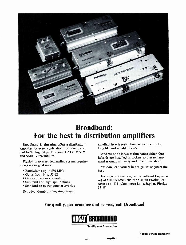
Broadband: For the best in distribution amplifiers
Broadband Engineering offers a distribution amplifier for every application from the lowest cost to the highest performance CATV, MATV and SMATV installation.
Flexibility to meet demanding system require-ments is our goal with:
• Bandwidths up to 550 MHz • Gains from 14 to 50 dB • One and two-way operation • Sub, mid and high-split options • Standard or power doubler hybrids
Extruded aluminum housings insure
excellent heat transfer from active devices for long life and reliable service.
And we don't forget maintenance either. Our hybrids are installed in sockets so that replace-ment is quick and easy and down time short.
We don't cut corners in design, we engineer the best.
For more information, call Broadband Engineer-ing at 800-327-6690 (305-747-5000 in Florida) or write us at 1311 Commerce Lane, Jupiter, Florida 33458.
For quality, performance and service, call Broadband
AUGAT BROADBAND Quality and Innovation
Reader Service Number 8

Desired specifications of pay cable traps
Alist of desired specifications is developed in this paper, with a discussion of each, for a trap in
channel A (121.25 MHz). The specifica-tions are intended to describe a filter whose performance will be predictable over a wide range of environments and with many different TV receivers. Also discussed are the differences to be ex-pected in operating parameters of fil-ters for channels higher and lower than channel A.
Considerations discussed herein are: the critical portions of the signal to be trapped, the parameters needed to ef-fect scrambling action in the receiver, specifications geared to ensure time stability, and specifications intended to cause poor to indiscernible audio in most receivers.
Notch Frequency: Desired visual car-rier ± 2 kHz
Temperature: -40°F to 140°F Depth of Notch: 45 dB at room temper-ature
Insertion Loss: Adjacent visual carrier 2 dB; all others 0.75 dB
Return Loss: All channels outside 3 dB points 16 dB
Frequency Stability: ±75 kHz 3 dB Bandwidth: 10 MHz 3 dB Notch Width: 32 kHz minimum; 100 kHz maximum
Power Protection: Withstand 250 VAC from center conductor to sheath
Shock: Withstand 20-foot fall to con-crete
Mechanical Configuration: Not remov-able with common hand tools
Warranty: One year
The rapid growth of pay cable has resulted in a heavy demand for a de-vice previously unknown to the cable industry: an inexpensive (relative to other filters in use in the industry), highly stable, weatherproof filter (or trap) designed to render a pay signal unwatchable, available in large quanti-ties to accommodate any given channel line-up found in the industry. Such a device is difficult to specify, and conse-quently not all filters are purchased
The cable industry is calling for an inexpensive,
stable trap.
Dan Pike, Vice President, Engineering, Prime Cable © 1976 NCTA, with permission, from NCTA Technical Papers, 1976.
under the same specifications. It is to the benefit of the operators
and manufacturers if both describe the unit by the same manner of specifica-tion, with changes in absolute values to accommodate special circumstances found in different CATV systems. The desired specifications are listed here with the appropriate discussion of each one.
Notch Frequency—The notch fre-quency should be specified as the as-signed visual carrier frequency of the pay channel with a tolerance of ±2 kHz to allow for slight variances be-tween equipment. This specification is intended to ensure that the center and deepest portion of the notch lies in the area of its maximum effect. Other pa-rameters will deal with the shape of the notch.
Temperature—The temperature range commonly specified for most CATV equipment lies from -40°F to 140°F, and these units should be compatible with other equipment operating in the industry. Certainly southern coastal areas might wish to relax these some-what for their particular needs, but fil-ters with good stability and tempera-ture compensation generally have little difficulty meeting the -40°F to 140°F temperature range.
Depth of Notch—The depth of the notch can be specified to satisfy one of two desires: either to effect scrambling action in the receiver or to reduce the visual carrier and consequently the carrier to noise value of the signal dis-played on the receiver to that which is generally accepted to be unwatchable. Most late-model color receivers will not reliably synchronize when the video carrier approaches an absolute level of -35 dBmV. The maximum drop levels found in
most systems rarely exceed 10 dBmV such that a notch depth of 45 dB is ad-equate to effect scrambling action in most receivers. If the notch, however, does not retain that value through the
channel of interest but rather only very near the visual carrier, as is the case in a pay cable trap, there are ap-preciable energy components within the desired channel (particularly within the areas of the color subcarrier and sound carrier). In addition, most receivers develop
AGC voltage by reference to the hori-zontal sync information, which is lo-cated within 15,570 Hz of the visual carrier. With the gain of the receiver circuitry at a relatively high value, these added energy components may aid scrambling effect by the generation of intermodulation products in the re-ceiver IF circuitry and detectors. Also aiding this effect are any adjacent channels that lie in the bandpass of the tuner and IF response of the receiver.
Added effects
These added effects may be used as a basis to modify the 45 dB specifica-tions at room temperature to include a
Cable Classics Traps, for the control of premium
channels, have been in use in cable for more than 10 years. In that time many trap products (and trap manufactur-ers) have appeared on the scene. The more successful may well have benefit-ted from this NCTA paper outlining technical requirements for effective pay TV traps. Do you know what notch depth, in
db, is required for effective scrambling action? Or what notch width is re-quired to effectively remove synchroni-zation components of the television signal? You may be aware of the poten-tial to degrade the performance of an adjacent channel, but do you know what the effects may be or how to mini-mize them? The author says now that the concept introduced in this paper, a 20 foot drop test (on to concrete—no less!), has proved to be a particularly effective means of qualifying designs to assure long term stability. This paper by Dan Pike provides not
only a list of the essential specifica-tions, but also a rationale for each.
Graham S. Stubbs, Vice President, Science & Technology, Oak Communications
46 Communications Engineering and Design August 1986

DoYou Have Even A Remote
Interest In Revenue Enhancement?
Everybody who sells converters talks about revenue enhancement. And most everybody who buys converters thinks it just doesn't work. Or, if it does, it
takes an awful lot of time and effort. Well—everybody's right. To stay on top of the market and to turn a profit at the same
time is not an easy task for anybody. So why make the job more difficult by installing a system with built in hardware obsolesence?
A M/A-COM converter system is the softest system you can buy. And here, soft means flexible. And flexible means you can package and repackage your services as often as you like—as often as you have to to turn a profit.
For example, our remote control, or even the volume control on the remote control, can be packaged and sold separately.
For a few other examples of how our con-verter was designed with the system operator in mind, call M/A-COM at 1 (800) 346-2266. We'll iiØ}u vi show you how to change the way you do busi-ness with the push of a button.
M/A-COM Addressable Converters 10737 Gateway West, Suite 350
El Paso, Texas 79.935 1 (915) 593-2250
Reader Service Number 9

CLASSICS
A poor picture is defined as one whose carrier to noise
ratio is 30 dB or less.
tolerance for the temperature extremes of 5 dB to allow a 40 dB specification at the two temperature extremes of -40 and + 140 provided that the filter re-turns to 45 dB at room temperature. The depth of notch specification, then, should read 45 dB at room tempera-ture and 40 dB at the temperature ex-tremes.
If the goal is to simply provide a snowy picture that may be considered unwatchable, then the value of the notch does not necessarily have to be so high since a 40 dB trap in conjunc-tion with a converter with a 13 dB noise figure and 10 dBmV input leaves a carrier to noise ratio contribution of the TV tuner and the system itself as being negligible. A poor picture has been defined as
one whose carrier to noise ratio is 30 dB or less. A barely viewable picture has been defined as one having a 27 dB carrier to noise ratio such that any value below 24 dB could be considered unwatchable. For the protection of the premium channel, however, specifica-tions written for a scambling effect would be advisable. While a 45 dB notch may render a
video signal viewed on a television set unwatchable, it most likely will not have a discernible effect on the audio portion of that signal since a filter de-signed not to suppress the visual car-rier on the adjacent channel by more than 2 dB will not suppress the aural carrier by more than approximately 10 dB. In cable systems where the aural carrier is operated 15 dB to 17 dB be-low the visual carrier, the audio will still be quite discernible.
Virtually every television set used in the U.S. today makes use of the 4.5 MHz difference between the aural and visual carriers with the use of an inter-carrier sound technique whereby after IF detection there follows a 4.5 MHz sound detector to recover the aural in-formation. The level of the 4.5 MHz carrier is
directly dependent upon a level of the visual carrier, so it is possible to place a value on the visual carrier at which or below which the value of the 4.5 carrier produces a garbled audio component. This absolute value has been estab-lished to be on the order of -45 dBmV to -50 dBmV, which means that a 55 dB or 60 dB trap is necessary if the
alt AND 4% II !FACTO* 211ellfC IT 'ULU
FIGURE I
40
I% ANO 4% kPACTO* 210111116 21 /VLSI
FIGURE 2
18 Communications Engineering and Design August 1986

Take a good look Channell's above
grade enclosures! Slotted bracket provides versatile mounting of all passive devices.
Padlock hasp, or optional high security locking — systems (Inner-Tite, Viewsonic, or Diversified).
Factory installed hot dipped galvanized stakes, brackets and accessories assure quality control.
"TV" identification permanently molded into top hood.
Vented to minimize condensation.
Top of pedestal easily removed and replaced.
Take a good look at Channell's high quality, above grade ABS
plastic enclosures and you'll discover why they're the best possible buy for your money.
Designed specifically for the CATV industry, all Channell enclosures come with stakes, accessories and locking systems factory installed. There's no need to buy separate stakes or go through the added chore of installing accessories. And,
because Channell stakes and
brackets are hot dipped galvanized after they have been
manufactured, you can be sure they are totally protected from corrosion.
For the complete story on Channell's above and below grade plastic enclosures, Cablecon® Cable-in-Conduit and
Carson Industries grade level boxes and vaults, call or write today.
Aesthetically pleasing, low profile housing provides complete 360° access working area.
Constructed of high quality ABS plastic. Corrosion-proof and never needs painting. Unaffected by severe temperatures from — 60°F to + 160°F.
8-inch ground skirt adds strength and pre-vents ground erosion around the pedestal.
CHANNELL COMMERCIAL CORPORATION
620 W. Foothill Boulevard Glendora, CA 91740 .Telex: 670-368 (800) 423-1863 Toll Free outside California (818) 963-1694 in California
Citanneft @CMMMOL=à1 gUPCULMICDGÎ Technology you can trust!
Reader Service Number 10

SINGLE PLANT ABOVE GRADE ENCLOSURES (Also available — A complete line of dual plant above grade enclosures)
CPH-508 Designed to house small diameter taps and for above ground service wire applications.
Dimensions: 5" diameter, 11" - 15" above grade.
Shipping: 12 per carton.
CPH-816 Houses tap and splitter combinations.
Dimensions: 8" diameter, 20" - 24" above grade.
Shipping: 2 per carton.
CPH-1022 Houses tap, splitter and line extender combinations, or amplifiers.
Dimensions: 10" diameter, 27" - 32" above grade.
Shipping: 2 per carton.
CPH-658 Houses all taps currently available in the CATV industry.
Dimensions: 6.5" diameter, 11" - 15" above grade.
Shipping: 8 per carton.
CPH-6512 Designed for special applications such as high water thresholds. Houses taps and filters, or one equalizer.
Dimensions: 6.5" diameter, 15" - 19" above grade.
Shipping: 8 per carton.
CPH-1006 Designed for special tap locations such as multiple dwelling units.
Dimensions: 10" diameter, 11" - 14" above grade.
Shipping: 2 per carton.
CPH-1016 Houses tap, splitter and line extender combinations, or small amplifiers.
Dimensions: 10" diameter, 21" - 25" above grade.
Shipping: 2 per carton.
CPH-1730 with 400MHz cover (550M Hz cover not shown).
Houses trunk amplifiers and passive combinations.
Dimensions: 17" wide, 30" long.
Shipping: 1 per carton.
(Low Profile CPH-1230 for line extender, tap and splitter combinations not shown.)
Channefl Commercial Corporation designs and manufactures the broadest selection of free-breathing above grade pedestals, and airtight and watertight below grade enclosures available anywhere. In addition, Channell is the exclusive representative for Integral Corporation's Cablecon® Cable-in-Conduit and Carson Industries grade level boxes and vaults.
For complete information on Channell's total packaging concept, call or write today.
CHANNELL COMMERCIAL CORPORATION 620 W. Foothill Boulevard Glendora, CA 91740 .Telex: 670-368 (800) 423-1863 Toll Free outside California (818) 963-1694 in California
Change MML 12i1 MOM. C)IPICDEGSUIJCI
Technology you can trust!
Reader Service Number 10

FIGURE 3
CLASSICS
The reduction of the visual carrier is not absolutely
certain to produce garbled audio.
%tot_
.41 r"-
. ---
t% AND 4% II FACTOR Mate 2T Pe.«
FIGURE 4
maximum subscriber levels are 10 dBmV. The reduction of the visual carrier is,
however, not absolutely certain to pro-duce garbled audio since the pay aural carrier can beat with any adjacent car-rier or even with high level luminance components if the trap is very sharp in the IF detection process and produces a 4.5 MHz component that the FM de-tector in the receiver will receive.
Since the gain of the receiver cir-cuitry is relatively high, many more distortion products will be presented to the FM detector and, depending on the alignment and fine tuning range of the receiver, it may be possible to fine tune to receive discernible pay channel audio even when the pay visual carrier has been attenuated 90 dB or more. The only sure way to reduce the au-
dio to an indiscernible level in every re-ceiver is to reduce the aural carrier level before IF detection. This may present a problem to upper adjacent visual carriers, particularly for opera-tion above the low VHF channels.
It is very important that the depth of the notch specification be consid-ered in conjunction with the other fre-quency and bandwidth specifications since it is entirely possible that a 60 dB notch can be placed in a channel in such a frequency position as to be barely noticeable. A 45 dB trap is not effective unless it attenuates the infor-mation within ± 15.75 kHz of the pay visual carrier by 45 dB.
Insertion loss
Insertion Loss—Insertion loss for all channels other than the adjacent chan-nel to the trapped channel should be 0.75 dB maximum. This should include any peak to valley or other variations in the response. The adjacent channel carrier should not be attenuated by any value more than 3 dB for the aver-age home receiver to be unaffected, and the figure of 2 dB provides ade-quate margin for variance between re-ceivers. While the trapped pay TV channel is
not offered to the subscriber and by yet-unqualified opinions doesn't have to be tested to meet the FCC stan-dards, the adjacent channel does have to meet them, and a value of 2 dB at the visual carrier is intended to pro-
Communications Engineering and Design August 1986 21

CLASSICS
Tests have shown that the trained eye can begin to
determine differences in the transient response.
vide a reasonable variance in that channel.
Since the filter response will return to about its insertion loss value above the visual carrier and will also drop an-other dB approximately to the lower channel limit, the recommended FCC limits of ± 2 dB may be met if the 2 dB insertion loss specification is observed for the adjacent channel.
Also, tests have shown (see Figure 1A) that the trained eye can begin to determine differences in the tran-sient response (where the picture con-tains sharp transitions) but cannot de-termine variances in the color satura-tions or hues at this level of adjacent channel attenuation. Photographs 1-4 show the variance
in test wave-forms through a demodu-lator that may be considered equal in quality to those of the average home receivers. Since the AGC voltage is developed from the 15.750 Hz compo-nents lying within 15.750 kHz of the visual carrier, the difference in the am-
plitude of the upper and lower 15.75 kHz sidebands is very slight and can be neglected. However, there is a discernible dif-
ference in attenuation between the components of appreciable energy con-tent at the lower end of the lower ves-tigial sideband and those of the same corresponding frequencies away from the carrier in the upper sideband, re-sulting in a reconstituted signal hav-ing variances in this response relative to equal amplitudes of components not passing through a trap having non-lin-ear attenuation throughout the adja-cent channel.
Since the gain is corrected using re-constituted lower frequency compo-nents, which are attenuated by the value of the slope of the incoming RF response, the corresponding value of the slope of the higher frequency com-ponents will be greater. Photos 1-4 show the effects of a re-
constituted signal for values of carrier attenuation given in Table 1. Also
shown in Table 1 are the values tenuation at the lower limits of the tigial sideband. Figure 1 A shows responses throu
the same demodulator with 2T, 12.5T and window test signals. Since most of the energy of the 2T pulse lies in the low-frequency areas of the video signal, its amplitude is af-fected less than that of the 12.5T pulse. The 12.5T pulse indicates a rela-tive chroma level increase with relative chroma delay. The 2T pulse reveals that the tran-
sient response as well as the amplitude is affected, as may be predicted by the change in phase relationships for those frequencies reconstituted from compo-nents above and below the visual car-rier since the components on the lower edge of the vestigial sideband are on the lagging edge of the filter and are affected more by any phase difference. The low to high frequency phase vari-ance is apparent by the observation of the 12.5T pulse.
Easy to read one dB resolution
BAR GRAPH
First real meter— you can hold in
your hand
LOW PRICE: $219.00
HIGH PERFORMANCE Shows two* individual Signal Levels in one dB steps (not an inaccurate composite
signal measuring device). Measures all channels when used with a standard TV Set Converter.
*Specify any two channel or pilot carrier combinations up to 300 MHz.
Available at major CATV Distributors Call or write for free color brochure
Reader Service Number 11
Sadelco,Inc. 75 West Forest Avenue, Englewood, New Jersey 07631 201.569-3323 General representative for Europe: Catec AG Luzern/Switzerland, Habsburgerstr 22. Tel. 041-23-90-56 Telex: TELFI 78168

Micro BeamTM solves the nrofit nuzzle
Total Customer Service: • 1 Year Parts/Labor Warranty NO CHARGE • Installation of Micro-Beam" Equipment
• Path Alignment • F.C.C. Application Help • Feasibility Study
NO CHARGE NO CHARGE NO CHARGE NO CHARGE
The Puzzle: How to generate more revenue while minimizing capital expenditures, and still ensure subscriber satisfaction.
rali Channel Master Division of Avnet, Inc. P.O. Box 1416, Industrial Park Drive, Smithfield, N.C. 27577 • (919) 934-9711
The Solution: Cost-effective plant expansion using Micro-Beam" broadband microwave relay systems
from Channel Master®.
Channel Master® makes CARS-band microwave
technology affordable AND SIMPLE for systems of any size. Micro-Beam" specialists offer more customer services at no charge than anyone in the business.
Compare Micro-Beam": the SIMPLE choice in
CARS-band microwave.
Reader Service Number 12 Communications Engineering and Design August 1986 23

CLASSICS
Phase relationships will be determined largely by the
alignment of the subscriber's receiver.
Phase relationships
These phase relationships, ampli-tude, variances and transient response differences, will be determined largely by the alignment of the subscriber's receiver, but the effects of the trap will be additive in any case. The fact that the trained eye may begin to see the ef-fects on using an average representa-tive receiver with a filter whose upper adjacent is attenuated beyond the val-ues given in Table 1 is used as a basis for the specification.
Return Loss—Since taps commonly used in CATV systems have return loss specifications of 15 dB or better, the trap used in conjunction with these should have at least an equal return loss except, of course, within the ef-fects of the notch. All channels other than those within the 3 dB points of the trap should exhibit a return loss of 16 dB or better. Of course, systems with taps that have better or worse re-turn losses may wish to alter these numbers slightly.
Tests at United Cable have shown
Photo
1 2 3 4
Table 1
Attenuation, dB at Visual Carrier
Reference 1.4 2.3 2.6
1 MHz Below Visual Reference
Reference 2.1 3.0 4.5
that a feeder line with traps on roughly 50 percent of the tap spigots exhibit-ing return loss of 11 dB does not result in a measurable difference in the re-sponse of that feeder line, nor does it result in discernible impairment of the adjacent color picture or any other channel when viewed by trained ob-servers. The tap values on the tested feeder line ran from the high 20s to 8 dB, and the minimum isolation specifi-cation of the taps was 26 dB. Frequency Stability—The frequency
stability of the notch is important to ensure that the critical components remain at the attenuation value that has been chosen. To ensure that g notch retains its position in the fre-quency spectrum a specification of 75 kHz across the temperature ex-
tremes has been shown to be a valid specification. Measurement of fre-quency for any attenuation value cho-sen should not vary more than ±75 kHz over the -40°F to 140°F extremes.
$68900 4
One time only! Get the popular DX DSA-643A satellite receiver from TELE-WIRE for just $689.
The DSA-643A offers commercial quality features you wouldn't expect at such a low price: 24 channel synthesized tuning, unique threshold extension circuitry, dual block downconversion, and a descriminator circuit for signal demodulation.
Take advantage of this special price. Order as many receivers as you like — but do it now. This is a limited-time offer that won't be repeated. (Companion DSA-54I block downconverters also available.)
To Order: call 8001645-9510 (in NY 516/293-7788)
Ask For Department 'H'
Trzerocœr SUPPLY CORPORATION
Corporate Headquarters: 7 Michael Avenue • E. Farmingdale, NY 11735
Reader Service Number 13 24 Communications Engineering and Design August 198E;
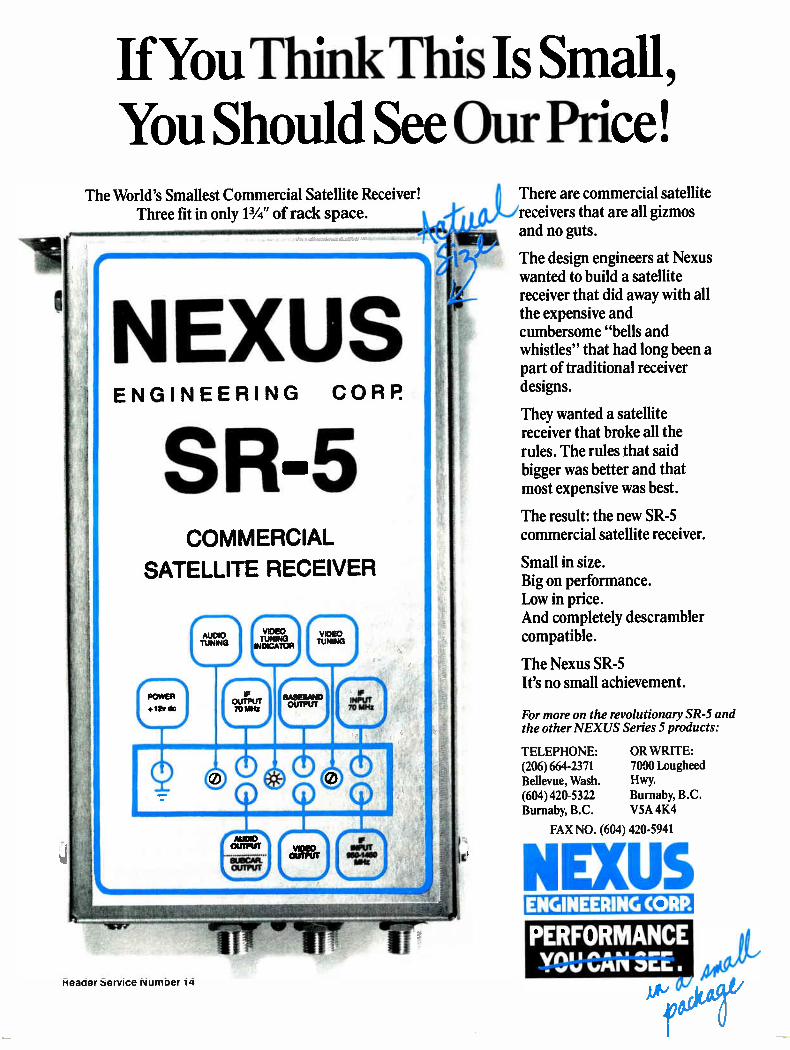
If You Think This Is Small, You Should See Our Price!
The World's Smallest Commercial Satellite Receiver! Three fit in only 11/4 " of rack space.
NEXUS ENGINEERING CORP.
SR-5 COMMERCIAL
SATELLITE RECEIVER
There are commercial satellite receivers that are all gizmos and no guts.
The design engineers at Nexus wanted to build a satellite receiver that did away with all the expensive and cumbersome "bells and whistles" that had long been a part of traditional receiver designs.
They wanted a satellite receiver that broke all the rules. The rules that said bigger was better and that most expensive was best.
The result: the new SR-5 commercial satellite receiver.
Small in size. Big on performance. Low in price. And completely descrambler compatible.
The Nexus SR-5 It's no small achievement.
For more on the revolutionary SR-5 and the other NEXUS Series 5 products:
TELEPHONE: OR WRITE: (206) 664-2371 7000 Lougheed Bellevue, Wash. Hwy. (604) 420-5322 Burnaby, B.C. Burnaby, B.C. V5A 4K4
FAX NO. (604) 420-5941
NEWS ENGINEERING CORP.
PERFORMANCE YOU CAN C.L.
Reader Service Number 14

CLASSICS
Cable TV equipment operates in environments and over bandwidths
surpassed only by a few industries.
it a band stop filter, a trap, or a band reject filter, is such that its operating conditions are somewhat opposite to that of most other equipment found in the industry.
It has to operate with very high cir-cuit Qs and very high stability yet over very narrow bandwidth, where the other equipment in the industry oper-ates over a very broad bandwidth. Slight physicial displacement intro-duced by shock may have catastrophic effects on the action of the filter. For this reason, the unit must be
able to withstand a 20-foot fall to con-crete to ensure that it will retain its electrical performance during and after installation. It also gives a relatively good idea that the unit will perform well with long-term environment im-pacts and gives a good idea that the mechanical exercise caused by temper-ature extremes over the years will not adversely affect the unit.
If a unit can be installed with corn-
mon hand tools, it may quite naturally be removed with common hand tools. Since the pay channel represents an annual worth of approximately $100 to the trapped subscriber, the propensity for him to steal the service is dramati-cally increased over that of the theft of the normal cable service. Where economically feasible, the fil-
ter should lock to the tap mechanically and not be removable except with spe-cial tools not normally available. Other alternatives to that, of course, include the use of a locking "F" connector or other arrangement on the subscriber's drop to mechanically lock the drop to the filter rather than the filter to the tap. The disadvantage of this method is
the availability of type F connectors at hobby shops and the likelihood a po-tential pay subscriber may connect himself at a point on the tap side of the filter. In apartment boxes and some underground installations there is the
• Sure-fit for quick simple installation.
• Plated, hardened, flat-headed Steel masonry nails, pre-assembled ready for use.
• Sizes to fit all coaxial cables, including quad and double shielded, both single and dual systems. Available in black, white and grey.
• Sold by most leading distributors — Ask for Tower by name.
• Write today for samples, literature and a copy of Tower Cable Clips test results as required by the British Telephone Com-pany, giving name of your supplier.
WELDONE TRADING CO. INC. 1401 Legendre Street W. Suite 106, Montreal, Quebec H4N 2S2 (514) 381-8861
reliable padlock for security. Regardless of the type of mechanical
security, he may connect himself to a neighboring pay drop. The inclusion of the mechanical locking specification is to indicate to the manufacturer the de-sireability of that feature.
One year warranty
Cable television equipment operates in environments and over bandwidths surpassed only by a few industries. The inherent nature of this narrow band device suddenly developed for pay cable use dictates the concern for its long-term stability. Component changes, mechanical exercise through temperature extremes, water absorp-tion, potting compound aging effects and countless other factors can affect the long-term stability of the unit. The unit should be warranted to exhibit these outlined specifications for a pe-riod of one year. These specifications were drawn for
units operating on Channel A and rep-resent reasonable specifications for that spectral area. Filters that are in-tended to operate at higher frequencies into the high VHF or super band must have relaxations in the 3 dB band-width since that parameter may be ex-pressed as a percentage of center fre-quency and used as a rough estimate of. performance for channels above the lower mid-band. For channels in the low VHF area
the 3 dB value may be expected to re-duce by approximately the same per-centage value. There are many other conditions
that come into play in the actual de-sign, and the use of the percentage es-timations yields only crude approxima-tions. Certainly with the vacating of upper adjacent and lower adjacent channels units may be used on chan-nels in the high VHF and super band. However, the sacrifice of those two
channels involves the sacrifice of an important resource of the system— that of valuable spectrum space that can never be used for distribution of information to all subscribers except when the filters are removed. Units operating in the low VHF
band have a spectral opening given them by the FCC in the 4 MHz space between channels 4 and 5. Units on
Reader Service Number 17 28 Communications Engineering and Design August 19Mi

Direct Mail Works
Have you ever wished you could reach key decision makers at virtually every cable system in the United States with your marketing message? Now, you can!
Reach more than 6,000 cable systems directly with CableFile Database mailing lists.
Source: CableFile/86 database.
Titles available: System name only or the following titles with personnel names included on over 95% of the labels. System Manager, Chief Engineer, Marketing Director.
Cost: Lists are $550 each, either by system name only or with personnel title/name included. Lists also available on floppy diskettes for $1,500 each.
Method of Addressing: Four-up Cheshire labels, zip sort. Charge for PSLs (pressure sensitive labels) is $7.
Terms: Prepayment required. No cancellations accepted after shipment.
Delivery: All lists shipped within two weeks of receipt of order. Overnight delivery upon request. Lists are shipped directly to you and, thus, become your
property. No bonded mailing house is required.
Contact: Kathy Berlin at (303) 860-0111.
ITC I INTERNATIONAL T 600 GRANT, SUITE HOMSON COMMUNICATIONS INC. 600, DENVER, CO 80203
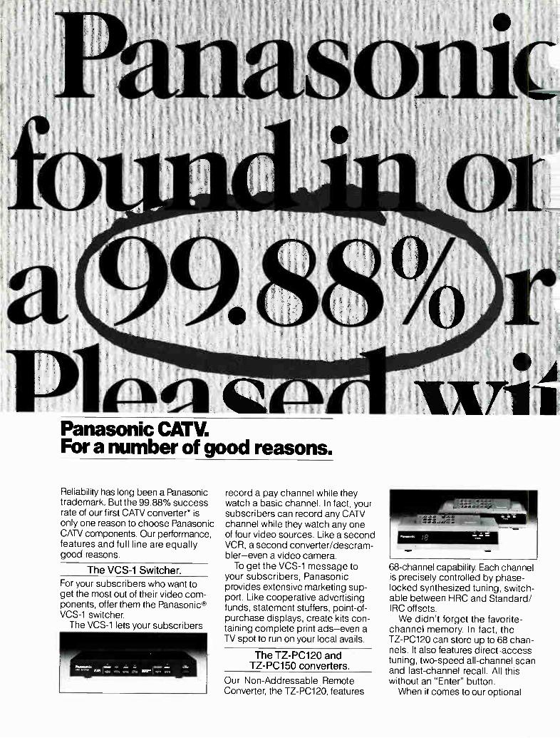
Panasonic CATV. For a number of good reasons.
Reliability has long been a Panasonic trademark. But the 99.88% success rate of our first CATV converter* is only one reason to choose Panasonic CNN components. Our performance, features and full line are equally good reasons.
The VCS-1 Switcher.
For your subscribers who want to get the most out of their video com-ponents, offer them the Panasonic® VCS-1 switcher. The VCS-1 lets your subscribers
record a pay channel while they watch a basic channel. In fact, your subscribers can record any CATV channel while they watch any one of four video sources. Like a second VCR, a second converter/descram-bler—even a video camera.
To get the VCS-1 message to your subscribers, Panasonic provides extensive marketing sup-port. Like cooperative advertising funds, statement stuffers, point-of-purchase displays, create kits con-taining complete print ads—even a TV spot to run on your local avails.
The TZ-PC120 and TZ-PC150 converters.
Our Non-Addressable Remote Converter, the TZ-PC120, features
68-channel capability. Each channel is precisely controlled by phase-locked synthesized tuning, switch-able between HRC and Standard/ IRC offsets. We didn't forget the favorite-
channel memory. In fact, the TZ-PC120 can store up to 68 chan-nels. It also features direct-access tuning, two-speed all-channel scan and last-channel recall. All this without an "Enter" button. When it comes to our optional
parental control, the TZ-PC120 lets your subscribers lock out the sensitive channels they don't want their children to see, without affect-ing the remaining channels. And thanks to our innovative Stored Charge Non-Volatile Memory, parental control channels and other memory functions will not be affected by a power outage. There's also an 18-button infrared remote control. It's compact, controls every function and comes complete with Panasonic batteries.
For your subscribers who want even more, there's the TZ-PC150. It has all the features of the TZ-PC120 plus volume control and mute. Parental control and base-band audio and video outputs are optional.
The new addressable PC-200 converter.
When it comes to your headend, the new PC-200 addressable converter
can help give you a head start. Downloadable features include channel map, channel authorization, clear parental control, initial activation and emergency alert. The PC-200 also features 68
channels, a full-function infrared remote control, electronic parental control, favorite-channel recall and
two-speed scan. Pay-per-view capabilities include
simultaneous events, multi-episode events and both inclusive and exclusive events.
Panasonic CATV components. The performance and features your subscribers want. The reliability you demand. •Based on in-warranty repairs aso' 4/1/86
f DM all converters sold since 8/84
For more information, contact Panasonic Industrial Company, Video Communications Division, One Panasonic Way, Secaucus, NJ 07094. Or call:
East Coast: (201) 392-4109 West Coast: (415) 672-2592
Panasonic Industrial Company Reader Service Number 19

CLASSICS
COLE LINK
INC.
The cable operators converter store and a whole lot more.
280 Co-zzins St., Suite 2-4
Columbus, Off 43215
(514)221-3131
Let us add you to our long list of satisfied customers. Just to mention a few:
—Buckeye Cablevision Toledo, OH
—Consolidated TV Cable Frankfort, KY
—Tri-County Communications New Richmond, IN
—Continental of Ohio Findlay, OH
—Monroe Cablevision Monroe, MI
—Centel of Iowa Burlington, IA
Reader Service Number 20
Observation of filter performance may be done by watching the trapped channel on service calls to non-paying subscribers.
channel 5 have that 4 MHz with which to recover their 3 dB bandwidth with-out adversely affecting the aural car-rier of channel 4.
Also, some designs incorporate 3 dB bandwidth sufficiently narrow to be used in the lower four channels with-out adversely affecting lower adjacent sound or color subcarriers, while keep-ing the required stability. The spectral area below channel 2, of course, con-tains no useful information to the sub-scriber, and units operating in that area have no lower adjacent problems. The program of trapping non-pay
subscribers must be carried through with the highest integrity possible for many reasons. The filter protects a ser-vice with an annual worth of $100 or more, and its performance has an ef-fect on the number of pay subscribers since inadequate performance may let a poor signal reach the home. A poor signal relative to the other
cable signals offered at a cost of a few cents per signal per month, may, in the eyes of a subscriber, become a signal good enough not to be worth $8 to $10 more per month to be made better.
Also, subscribers paying for the pre-mium channel often fail to see the dol-lar difference between their good sig-nal and their neighbor's free snowy sig-nal. These undesirable events may be avoided by 100 percent incoming in-spection and rigid testing for these specifications presented on a sample lot of units from each production run. Continued observation of filter per-
formance may be carried out by ob-serving the trapped channel on every service call to a non-pay subscriber. General trends that may be noticed
during the testing of filters may be the slight dependency for the scramble ef-fect on the average picture level, depths of modulation and picture infor-mation. A test pattern such as the cross
hatch and dot pattern where rapid transitions are apparent will effect the scrambling action more so than dark movie scenes since dark scenes have more visual carrier available to the re-ceiver, and any scrambling action in-troduced by the rapid transitions is not apparent. For systems using converters, a re-
ceiver that does not synchronize with the fine tuning at its normal range may
synchronize if the fine tuning is ad-justed to one extreme partly because of the frequency response of the televi-sion receiver and partly because of the response of the converter. Perhaps by the establishment of a
set of desired specifications with the flexibility to adapt them to every par-ticular situation to be encountered in the CATV industry, the industry's needs may be more closely conveyed to the manufacturer, and the manufactur-er's response may be more closely cor-related with the predetermined CATV operator's need.
References
Bostick, Glynn; "Trap Selection— Some Notes on Basics." Unpub-lished article, Microwave Filter Company, October, 1975.
Ennes, Harold, E; Television Broad-casting: Systems Maintenance. Howard W. Sams & Company, Inc.: Indianapolis, Indiana, 1972.
"Pay TV Traps—Just How Bad is the Language Leakage Problem?" CATJ, Vol. 2, No. 11, November, 1975, p. 12.
Pillow, Jerry; personal interview, Nov-ember, 1975.
Rhodes, Charles W.; "The 12.5T modu-lated Sine-Squared Pulse for NTSC," IEEE Transactions On Broadcasting, Vol. BC 18, No. 1, March, 1972.
Schmid, Hans; "The Measurement of Linear Chroma Distortion in NTSC TV Facilities," IEEE Transactions On Broadcasting, Vol. BC 18, No. 3, September, 1972.
Wilbanks, Jim; personal interview, February, 1976.
Wilson, Roger; "Pay TV Filters," Communications Engineering Dig-est, Vol. 1, No. 2, November, 1975, p. 21.
Correction In CED's July issue, an error was
made in the SMATV Buyers Guide. On Budco Inc.'s listing, the National WATS number should read (800) 331-2246 and the in-state (Oklahoma) col-lect number is (918) 252-3420. CED apologizes for any inconveni-
ence or problems this error may have caused.
32 Communications Engineering and Design August 1986
DIE MOST MEMORABLE FEATURE «THE NEW WATCHMAN®I ISYOU CAN FORGET ff.
DNB
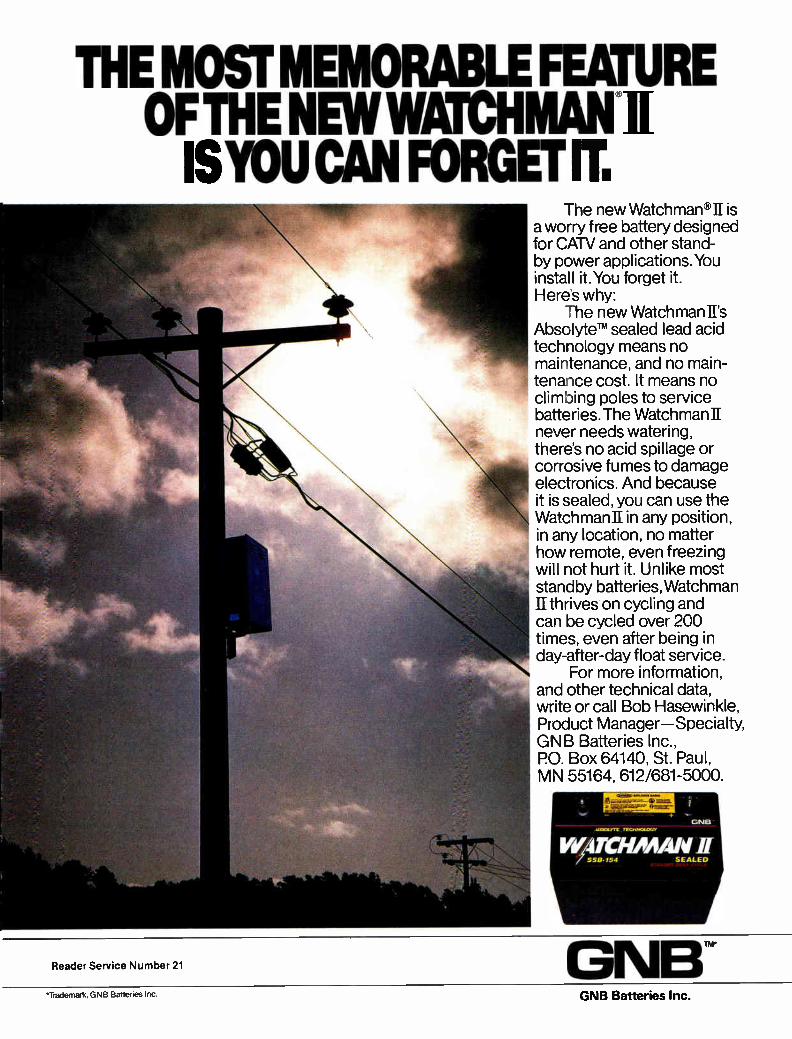
The new Watchman v11 is a worry free battery designed for CATV and other stand-by power applications.You install it. You forget it. Here's why:
The new Watchman II's Absolyten" sealed lead acid technology means no maintenance, and no main-tenance cost. It means no climbing poles to service batteries. The Watchman II never needs watering, there's no acid spillage or corrosive fumes to damage electronics. And because it is sealed, you can use the Watchman II in any position, in any location, no matter how remote, even freezing will not hurt it. Unlike most standby batteries, Watchman II thrives on cycling and can be cycled over 200 times, even after being in day-after-day float service.
For more information, and other technical data, write or call Bob Hasewinkle, Product Manager—Specialty, GNB Batteries Inc., PO. Box 64140, St. Paul, MN 55164, 612/681-5000.
Reader Service Number 21
*Trademark, GNB Batteries Inc GNB Batteries Inc.

Outage control problems: here's what to do
The onset of lightning during a passing thunderstorm can be a hair-raising experience for anyone,
but for a cable system operator, it can be a real headache. With lightning of-ten attracted to aerial cable by the power line that usually runs just above it, systems in certain areas of the coun-try may suffer the effects of hundreds of strikes every year. And while the vast majority of those strikes are not direct hits on cable plants, the surges that transfer to the cable have enough power to easily blow amplifiers, caus-ing an unwanted outage.
In order to reduce the effects of lightning, it's important to bond and ground each pole beyond the specifica-tions called for by national electrical codes, says Roy Ehman, vice president of engineering for Storer's Kentucky and Virginia region. "When I say effective grounding, I
mean driving successive eight-foot lengths of rod into the ground until you can drive them no further." He
Lightning and trench digging are the major
causes of cable outages.
suggests that these "private" ground-ing rods—used to drain surge current —be driven as deep as 24 or 32 feet deep. "If you're lucky, you might hit water or subterrainian moisture and achieve a ground of less than one Ohm," he says. Beyond that, surge arresters that
last for several milliseconds and have a fast rise time should be placed throughout the system, Ehman says. "I don't believe surges travel through the power supply," he says. "I believe they come directly induced into your neutral, hence into your strand and your cable itself. That's where the pro-tection needs to be." Nick Worth, vice president of engi-
neering at Telecable, says it's impor-tant to realize surges come through the
Trench digging often results in cable outages.
power company's connections. So, in his systems, he has installed protec-tors capable of absorbing up to 500 joules of energy at the input to standby power supplies and at the headends.
In areas where there is a lot of elec-trical activity, Telecable has gone the extra mile to effectively bond it's strands.
Bonding tricks
"The National Electrical Safety Code requires us to bond our strands to the telephone company's strands and to the power company's vertical grounds," Worth says. "It's a safety requirement we must do but it creates a problem in that it gives a pass through which lightning can be trans-ferred from the power lines to our plant. "A little trick we've discovered is to
run our own vertical and bond at the base of the pole. And we also take some jacketed bonding wire and wrap it around a suspension clamp bolt to make an RF choke and we use that as a bond. It seems to help keep from cou-pling some high frequency surges into our plant," he says. Bob Dattner, vice president of tech-
nical operations for Media General in Fairfax, Va., grounded the input and output of each amplifier in his system, but isn't convinced it's been effective for him. "We did it because it seemed like the right thing to do and we spent a lot of time checking those grounds," he says. "Whether that saves me out-ages or not, though, I don't know."
In spite of all the precautions, light-ning can still cause outages, so it's im-portant to beef up standby power sup-plies where lightning strikes most of-ten, says Telecable's Worth, who has some systems backed up 100 percent while others are covered on strategic major trunk runs. But, after the deci-sion is made to add standby power, it is critical that the supplies be main-tained properly so that they will work when needed. After selecting a good, reliable unit,
Worth says, the key to keeping it in good shape is to properly set the bat-tery charge voltage with a digital volt-meter. "Even a few tenths of a volt er-ror can cause batteries to boil over and
34 Communications Engineering and Design August 1986

Wet Standby Power A Good _ Name
Unlike some other choices, Alpha maintains the Good Name of Standby Power by offering a reliable and failsafe approach—as we have right from the start. We call it the "single ferro transformer" concept.
This design concept leaves the ferroresonant transformer always connected to your Cable plant, regardless of power failures or other disturbances, and does away with the need for a second transformer.
The battery driven inverter takes over from the downed line in the primary winding of the transformer, ensuring an unaltered output voltage and waveform. Overload and short-circuit handling characteristics remain unchanged. In addition this same transformer is used to charge the batteries, providing a high current recharge of the batteries after a power failure, a feature lacking in most competitive designs.
This concept needs fewer components which translates into higher reliability. Because
REPRESENTED IN YOUR AREA BY: A & M COMMUNICATIONS (612) 920-5215 •MN, WI, ND, SD, IA R. ALAN COMMUNICATIONS (317)849-7572 •MI, IN, KY. IL. OH, MO, KS BILL DONALDSON CO. (206)745-3454 •WA. ID, MT, OR
MICRO-SAT SIE, INC. (404)971-102 •GA. FL, NC, SC, AL, MS, IN NCS INDUSTRIES (215) 657-4690 •PA, NJ, DE, MD, VA R.F. TECHNOLOGIES (516)623-5899 •NY. NH. ME, VT, CT, MA, RI
the inverter cannot be activated, even with the line relay contact "stuck", this concept also gave us the fail-safe feature that helped us to obtain both UL and CSA approvals. And that gives a good product a good name.
Of course there are more reasons for Alpha's leadership and good name in Standby Power. Features such as Temperature Compensated Charging matched to the battery type and Automatic Selftest and Equalizing, to name just two.
Alpha was the first to offer Remote Status Monitoring for it's power supplies on a stand-alone basis.
And now Alpha has introduced two new State-of-the-Art Standby Power product lines. The FT series, a fast transfer type for critical loads up to 500VA, and the APCG series for true UPS performance up to 1500VA at Standby prices. Our ongoing efforts to give you the best
engineered products will continue to give Standby Power a good name.. ALPHA.
ADVANCE TELECOM (602)998-4441 AZ, NM,UT,COWY•(707) 255-2010 CA,NV.(714) 521-9833 CA, NV DISTRIBUTED BY: ANIXTER COMMUNICATIONS 800-323-8166
ALPHA TECHNOLOGIES • BELLINGHAM WA (206) 671-7703 (206) 647-2360 • BURNABY BC (604) 430-1476 Reader Service Number 22
YOUR BEST BUY IN THE LONG RUN

NOW YOU CAN CHOOSE!
HYPOWER-XL • HYPOWER-LANS • No Maintenance — Sealed
• Starved Electrolyte — SAFE - No Fluid To Spill • Superior Performance — Hybrid Lead Calcium
HYPOWER-n
HYPOWER-XL
Recommended for CATV, Telephone Systems and General UPS Usage
HYPOWER-LANS
Recommended for LANS, Computer and Data Type Usage Extended Warranty
HYpowERI280 = Recommended for Hostile Environments (Extreme Hot or Cold) Infinite Storage Life
Maintenance Required
Distributed by
ADVANCE Telecom Inc. In Association with Westec Communications
14405 N. Scottsdale Road • Scottsdale, AZ 85254
(602) 998-4441
Tuff, Hypower Says Back Up Your Line
e BEST!
Los Angeles (213) 650-4812 NAPA, CA. Reader Service Number 23
(707) 255-2010
OUTAGE CONTROL
The battle of fighting construction dig-up-related outages has become one
of economics.
drastically shorten their life," he advises. It is that need for constant maintenance that has kept Dan
Liberatore, director of engineering at Adelphia Communica-tions, from investing in standby supplies. "Standby power supplies are good, if you keep after them," he says. "But if you put them up there and never pay any attention to them, they're a waste of money." That money is better spent working with the power com-
pany to solve outage problems, says Fritz Baker, regional engineer for Viacom in Cleveland. "Typically, a cable system will pay $2,000 to $3,000 for a good standby power supply," he says. "I would rather approach the power company and pay that amount of money to clean up the power grid that serves the cable plant. I would rather fix the problem than apply a band-aid solution." Media General's Dattner says, however, that his biggest
cause of outages is construction dig-ups. It's an ongoing bat-tle for Dattner, who has 1,000 miles of underground plant in an area where they're building thousands of new homes ev-ery year. And the battle has turned to one of economics.
"I think the best thing to do is to hit these guys in the pocketbook—let them know you're serious. They're still going to cut you, but you need to get after them for some money and maybe some will be more cautious." And because a cut cable will eventually have to be completely replaced, Dattner bills the guilty party for the total replacement cost.
In cities where there is less construction activity going on, most systems can benefit from joining a "blue stake" com-mittee that advises systems of any digging that will be tak-ing place so system lines can be identified. "That seems to be working fairly well" for most of the Jones Intercable sys-tems, says Alan Kernes, vice president of engineering. Some Telecable systems have been using an orange tape
buried a few inches below the surface above the route taken by cable, says Worth. This way, when a person digs up the tape, he'll be alerted to what's underneath. Additionally, Worth says Telecable tries to bury its cable at a depth of two feet, a concept Viacom's Fritz Baker agrees with. "The key (to avoiding dig-ups) is to be the deepest guy in
the block," says Baker. "It's more expensive but it's the only way to go."
Amplifier failures
In an area that experiences numerous amplifier failures, it's important to look at the fuses, says Storer's Ehman. "The manufacturers fuse lightly to protect their equipment and their good name," he says. "Every time you replace a fuse in the beginning, increase it 30 percent or so from the original equipment until you find you're burning a few mod-ules, then back off one step. That will reduce your fuse blow-ing nuisance-type outages," he says. Another way to overcome a specific problem is to talk di-
rectly with the manufacturer to work out a solution. That's what Media General's Dattner and Jones' Kernes have done.
"I probably have 30,000 to 40,000 fuses in my system," says Dattner. "So if I blow a dozen fuses per week, it's really a low percentage but it's a lot of fuses." If you feel uncom-fortable experimenting with fuse values, Dattner suggests talking with the guy on the bench who built the amplifier.
If GUARD
POWER
DIV of AUDIOGIJARD
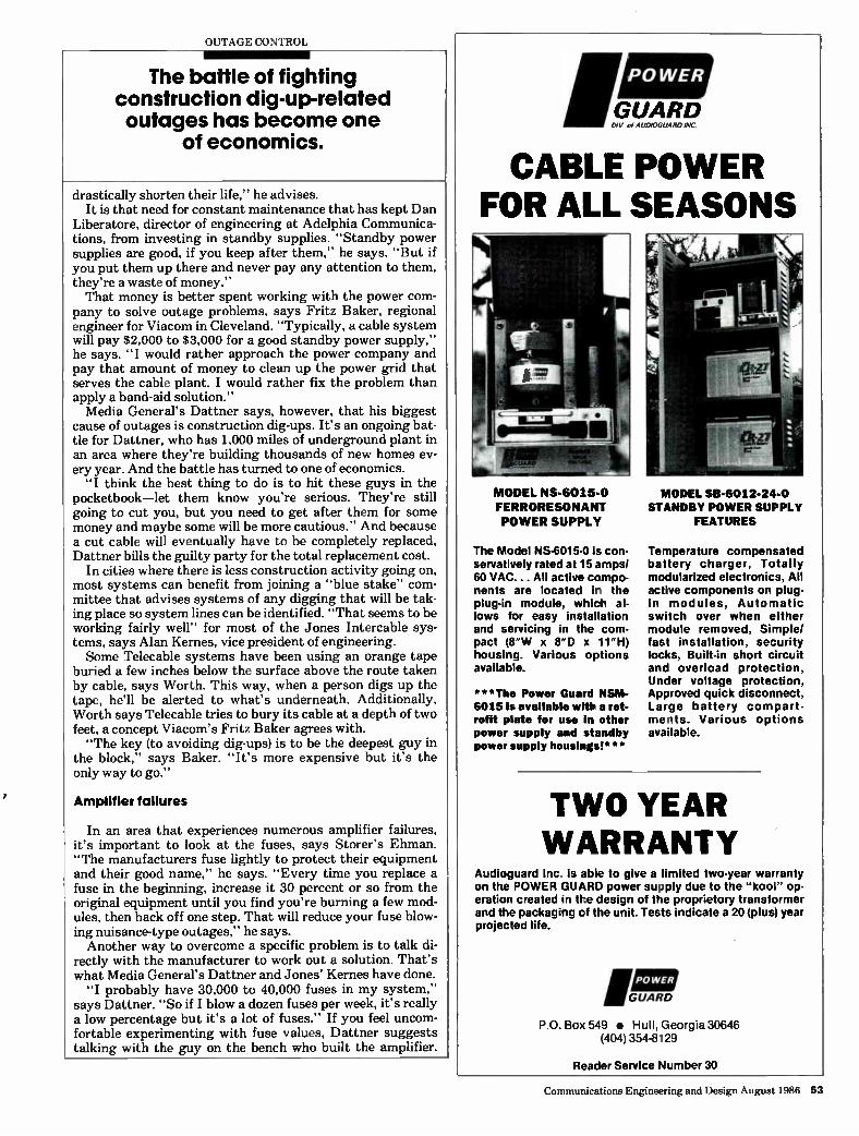
CABLE POWER FOR ALL SEASONS
MODEL NS-6015-0
FERRORESON ANT
POWER SUPPLY
MODEL SB-6012-24-0 STANDBY POWER SUPPLY
FEATURES
The Model NS•6015-0 is con-servatively rated at 15 amps/ 60 VAC... All active compo-nents are located ir the plug-in module, which al-lows for easy installation and servicing in the com-pact (8'W x 8"D x 111-1) housing. Various options available.
***The Power Guard NSM-6015 is available with a ret-rofit plate for use in other power supply and standby power supply housings!***
Temperature compensated battery charger, Totally modularized electronics, All active components on plug-in nodules, Automatic switch over when either module removed, Simple/ fast installation, security locks, Built-in short circuit and overload protection, Under voltage protection, Approved quick disconnect, Large battery compart• melts. Various options available.
TWO YEAR WARRANTY
Audioguard Inc is able to give a limited two-year warranty on the POWER GUARD power supply due to the "kool" op-eration created in the design of the proprietory transformer and the packag;ng cf the unit. Tests indicate a 20 (plus) year projected life.
'GUARD
POWER
P.O. Box 549 • Hull, Georgia 30646 (404) 354-8129
Reader Service Number 30
Communications Engineering and Design August 1986 53

OUTAGE CONTROL
It's also important to improve your system in the areas you
do have control over: namely, technician training.
"They make a lot of compro-mises when they put that fuse in and it may not be the best one for your part of the country. So it never hurts to get to the guy who put it in there and try to get his criteria for why he did it." Worth says it's a good idea to lab
test and select the amps that have the best immunity to surges. Additionally, Worth said he'd like to see amplifier manufacturers surge test every port of each amp to a standard "appropriate for cable" and then publish that speci-fication. "I think that would help," he says.
After doing as much as possible to overcome outages caused by circum-stances beyond your control, it's also important to improve your system in the areas you do have control over. First and foremost is proper technician training and an effective preventive maintenance program, says Dattner. "Those two things are critical in ev-
ery operation and underline everything
we do in terms of service, installation and everything else," he says. "If you do a good job on those two things, you get 90 percent of your problems taken care of."
Liberatore says he's in the process of improving the training program at Adelphia. "I think it goes a long way in outage control. First of all, it makes a guy a better trained technician and secondly, I think it charges his batter-ies a little," he says.
"I think we need to work on some of the basics," adds Liberatore. "A lot of our guys do a good job but they're not sure why they're doing it. As an engi-neer myself, I like to know why things happen—it makes my job easier."
All the engineers contacted agreed that eliminating outages goes a long way to improving customer satisfac-tion, but Telecable's Worth says even more needs to be done. We really feel we have to do the things we're doing and more in the future because subscri-ber tolerance for cable interruption is
going to be lower and lower."
Important lesson
One of the first places to look when you receive complaints of outages is within your own policies and proce-dures, advises Viacom's Baker. A few years ago, Cleveland city officials pre-sented the system with a list of out-ages—many just temporary, brief in-terruptions—and asked the company to explain them. And although each could be identified as just normal, rou-tine maintenance, Baker said an impor-tant lesson was learned. "When we saw what we were doing
to ourselves, we came up with some hard and fast rules that said that on any given trunk line, including the bridger, we will not turn off the system for sweeping, construction or headend work during the prime time viewing hours and that eliminated 90 percent of our reported outages," Baker says.
—Roger Brown
Prevention is the only protection Lightning rods attract lightning— that's their function. The only sure protection is to prevent the lightning from striking the structure and damaging the installations inside. That's what the VE RDA Lightning Deterrent does—it gives you protection from all lightning-associated problems by deflecting lightning. A positive corona is formed which deters positive lightning energy. The VERDA Lightning Deterrent can be applied in all situations requiring lightning protection—
Communications systems— microwaves—two-way radio —TV—FM—Nurad antennas —boats—police and fire stations—ambulances— telephones—trucks— It's round-the-clock protection against lightning.
This system has been storm-tested on the highest structure in the world
ÉLightning Deterrent Corp. 5321 South Kedzie Avenue Chicago, Illinois 60632 (312) 434-7912
The Proven Lightning Deterrent!
CAN YOU SPOT 15 IMPROVEMENTS?
Model 2901B rew.
Still only $695
complete.
Made
USA
DIGITAL TOR • CABLE FAULT LOCATOR
• Liquid Crystal Display •± 1% Accuracy • Feet or Meters Readout • 11,000 Feet Readability • Variable Sensitivity • Compact, Rugged Packaging • LCD Annunciators • Pocket-Size Manual
• Low Battery Indicator • Auto Zero • Powered Cable Warning • Improved Resolution • Longer Battery Life • Lightweight (only 3 lbs.) • Padded Carrying Case • One Year Full Warranty
manufactured by Riser-Bond Instruments
3430 Fujita Avenue
Torrance. California 90505-4078
(213) 539-8030 usturr tabu In Calif. (800)641-2288
Outside Cal if.(800)551 -2288
.ffloym and 1170A QUO (ci oges%
[Mann enS-14,Pod I CL kle,n09%, Pallenol ( L sloieounuuy 001 i• IL poquo0 yo/uo peigudwi ono eiudweo pooped I 6 am /Jean Oalawol ( a.0q0Un OAIZ-OVW ( ['Lee. • POP.% ( 9 eo.oaM MEMO imue.od S CLPOI 0a1M10 O1 ( P alipaS aueoll40 Mold 1owd IC .1.Marma, Vaal X) IL (0104v03 ILLoupsues amauaA ( L :81eMSUY
Reader Service Number 31
54 Communications Engineering and Design August 1986 Reader Service Number 32
MORE FOR LE$$ • III
(When WE say PROFIT BUILDER - WE mean YOUR PROFIT!)
CABLE POWER CL 737 V I • ENGINEERING EACELLENCE • FIELD PROVEN RELIABILITY • REALISTIC PRICE
• Hinged lid
• Easy access battery location
• Spill-guard battery trays (available)
• Insulated shelf for battery protection
• Modular construction
• Lightning arrestor
• Bottom indicator lights and entries
15 OPTIONS including • Remote Status Monitor • Automatic Performance Monitor
• Vandal and corrosion resistant galvanized steel pedestal enclosure
STANDBY POWER SUPPLY Model CL 737XL
0 LISTED Factory and Customer Service: 14860 N.E. 95th Redmond, WA 98052 (206) 882-2304
Service: Redmond, WA
(206) 882-2304 Deerfield Beach, FL
(305) 429-0870 Ontario, CANADA
(416) 629-1111
Reader Service Number 33
A Triple Crown Corporation

Fiber migration to LANs ancnocal loop
since the late 1970s, fiber optics in-creasingly has been the medium of choice for long-distance trans-
mission of voice signals by common carriers and private switched tele-phone networks. In the past few years, telco metropolitan trunks—especially in congested urban areas—also have migrated to fiber. But, in the years ahead, we undoubtedly will see increas-ing use of fiber in the local, campus and metropolitan network markets. That migration will occur at least
partly because the big buyers of fiber —long distance communications car-riers—are nearly finished constructing their networks. So the big push from fiber manufacturers will have to shift elsewhere. AT&T Communications, for example, is nearing the end of its fiber optic buying for long-haul traffic. By early 1987, the company should have 10,000 route miles installed, and that just about completes the system. Most of that cable is already ordered. MCI Communications Corp. has about 2,-500 miles of fiber installed and is look-ing to add 2,500 to 3,000 more miles this year. Ultimately, MCI's fiber mi-leage should total about 7,000 miles. Again, not too much buying remains to be done. At the Bell operating companies,
though, fiber installation continues briskly. Ameritech, one of the bigger buyers, plans to spend some $89.9 mil-lion on fiber this year. It spent about that much last year, and about $45.3 million in 1984. Southwestern Bell probably will buy $122.9 million this year, up from $76.1 million or so last year, and a whopping increase over the company's 1984 expenditures of $22.8 million. Without question, a big driver for fi-
ber at the local loop level is the threat of bypass. With competitors offering broadband transmission capabilities, the phone companies are reacting to protect their markets by adding even more wideband capacity than is needed at the moment. And although high-speed interoffice links have been the emphasis so far, it's safe to say the lo-cal Bells are taking a look at how lower-speed and shorter distance equipment might fit in. Which isn't to say the state-of-the-
art hasn't been changing at nearly the speed of light. Recently, 565 Mbps was
Massive quantities of fiber optic cable have gone into the long-distance and trunk
portions of the telephone network since 1980. The
local loop and local networks are next.
the standard. Fujitsu, though, recently developed an 810 Mbps system. And engineering work continues feverishly on 1.2 and 1.7 gigabits per second speeds. But higher transmission speeds alone will not ease the spread of fiber technology to local loop and LAN markets, because the problem of opti-cal switching and splitting still bedev-ils researchers.
In fact, a recent report by Frost & Sullivan, a New York research firm, predicts 76 percent per year growth for the fiber optic LAN market. The com-pany estimates that although fiber ac-counts for only 5 percent of the LAN market in 1984, it will be 15 percent of the market by 1990. But cost is still a factor at the mo-
ment. Although installation and main-tenance costs aren't far out of line with coaxial cable, the transmission and dis-tribution gear is. Optical sources, de-tectors, connectors and multiplexers can really push the cost of a fiber LAN up. Ungermann-Bass, a major Santa
Clara, Calif., LAN supplier, has experi-ence in baseband, broadband and fiber nets. And most of the fiber LANs the company has installed are inter-build-ing runs specifically designed for light-ning immunity or message security. In most cases, fiber isn't cost-competitive with coaxial cable, the company be-lieves. That could change in the next few
years, though. Optical transceivers in the $100 range should be available in the near future. That compares with a current cost in the $300 to $400 range. And optical connector and splicing technology is improving rapidly. How-ard Brunke, vice president, engineer-ing for Teleport Communications, says "AT&T has a rotary splice that's so easy to do, I could teach it to anybody
in five minutes." "The interoffice and long-haul mar-
kets are saturating, and it's in the local loop, especially distribution, that the significant sales will be made in the next few years," says Robert Bowman, president of Telco Systems Fiber Op-tics Corp. As early as 1988, the inter-office market could be saturated, Bow-man believes. In fact, he argues that within three years the local loop will surpass the long-haul and inter-office trunk markets in size of sales. As that change occurs, the relative
proportions of fiber and transmission equipment in the total system mix will change, Bowman says. Now, 65 per-cent of the sales represent fiber, and 30 percent to 35 percent are transmission equipment. But fiber in the local loop will require three to five times more hardware than does the inter-office market, he adds.
Significantly, video services are seen as a possible driver for rapid local loop penetration. Brunke's company is the firm that runs the New York Teleport and already has 130 miles of fiber run-ning in Manhatten. And while he's in a business communications, not con-sumer, video market, he argues that "PC terminals in the home will lead to fiber drops in the home. That'll free the voice line up. Higher-clarity video might be the driver after that." Bowman agrees with that assess-
ment, although he's more inclined to see local loop growth in two areas: dis-tribution feeder and point-to-point connections for very high-density areas. Of course, as one Bell Atlantic Corp. purchasing vice president has said: "More economic fiber cable for the feeder area would make it more fea-sible for the operating companies to run fiber into homes and office build-ings." A Southern Bell network planner
was also forthright. "We are starting to deploy a fiber network that will ex-tend into the home. Using one terminal that can handle voice, video and data, the consumer could control energy management, receive pay-per-view TV, and query a data base for informa-tion." Government, aerospace and local
area network markets are emerging, while the long-haul market will be flat-tening, says Joseph Hicks, senior vice
56 Communications Engineering and Design August 1986

FIBER OPTIC
Fiber will be used in local area networks, it seems safe
to assume.
president, sales and marketing, for Sie-cor. Although feeder loop probably is the near-term target, "Fiber drops to the customer premises will dwarf ev-erything we've seen to date," he argues. "By 1990 some $600 million in subscriber drop will be installed, and possibly $5 to $8 billion by 2000." And while LANs are widely seen as a
major growth area—perhaps the big-gest growth area in data communica-tions in the next few years—"fiber doesn't really solve any problems for the typical LAN user right now," says Albert Bender, president of FiberCom. "Most of the existing applications are for short distance, low-speed communi-cations, and fiber doesn't offer an edge there. It is being used where security is very important or where the environ-ment is electrically noisy." Right now, AT&T Network Systems
has to be counted the leader among
turnkey suppliers. But Siecor, a joint venture between Corning Glass and Siemens AG of West Germany, is pushing hard. ITT Corp's Electro-Op-tical Products Division, Ericsson Net-work Systems and Northern Telecom also are players. Major systems houses include companies like Plessey Tele-communications of the United King-dom, Fujitsu, Rockwell International, NEC, and Telco Systems.
Siecor began looking at local loop applications about 1985, and now has about 2 million km of fiber installed in the United States, nearly equalling AT&T's base. The company decided to set up a network of sales offices selling to the Bell operating companies, and introduced a feeder cable system to link central offices. The feeder can han-dle 565 Mbps, although Siecor thinks most local telephone companies will run transmissions at about 45 Mpbs.
The company estimates that between 1986 and 1989 there will definitely be a slowdown in fiber industry growth with the competition of the inter-city and long-haul networks, fol-lowed by a big subscriber loop push af-ter 1990.
Fiber will be used in local area net-works, it seems safe to assume. It's al-ready being used for trunking applica-tions at the local telephone loop level. What's harder to predict is lightweight technology's spread to the subscriber drop portion of the local telephone sys-tem.
Note: Bender also says that "only with a strong demand for subscriber services can the big move to fiber oc-cur." And more than one observer has commented that the real driver has to be video—without video, fiber doesn't make sense.
—Gary Kim
Thousands of mi
les
70
65
60
55
50
45
40
35
30
25
20
15
10
Bell operating companies 1985 fiber miles installed
Ameritech Bell Atlantic BellSouth NYNEX 46,000 34,000 66,000 26,000
264,000 miles total
PacTel Southwestern US West 41,000 Bell 19,000
32,000
Communications Engineering and Design August 1986 57
What you need is a one-handed economist...
ATV suppliers who've decided to chase the growing broadband local area network market don't
necessarily agree on how to identify or cultivate potential buyers of LAN equipment and services. But all agree that it is frighteningly tough to find those customers cost-effectively. Still, some vendors expect the LAN portion of their business to rival their CATV business in five years or so. What types of companies are we
talking about? Distributors like Anix-ter Communications or CWY. Manu-facturers like Jerrold, Magnavox and C-COR. Construction firms like Na-corn, AM Cable or RT/Katek. Cable manufacturers like Scientific-Atlanta or M/A-COM. Test equipment vendors like Comsonics or Wavetek. Compo-nent houses like Augat or Gilbert. And even MSOs like Viacom. Some of the players are sticking to
broadband. Others are branching out into fiber optics, small-aperture an-tenna or microwave installations. And if you can pull 75-ohm cable, you also can pull 50-ohm cable for Ethernet. A few players—not too many—already are bidding turnkey projects. A few more would like to work up to turnkey status. It's no easy job, though. For most, subcontracting has
proven to be the best way to partici-pate. Generally, the trick is to estab-lish a relationship with a firm that ac-tually bids the turnkey. That gives you a repeat business and keeps the cost of sales down.
New business And while most of the attention now
is going to new networks being in-stalled, down the road a new business is certain to emerge: maintenance. Broadband networks need periodic tweaking, and few owners of turnkey systems can afford to keep a staff oc-cupied full-time doing that. So provid-ing you can cluster your customers, maintenance contracts will emerge as a new revenue stream. And not just for suppliers. In some cases, CATV opera-tors may have just what's needed: an experienced staff familiar with the ins and outs of broadband network main-tenance; tools and equipment to do the job, and a local base of operations. -Running a CATV system, in and of
itself, doesn't mean a company's quail-
- . . Because, on the one hand, LANs are a good market. On the other
hand, you'll have trouble finding your buyer.
fied to maintain a data network. You need a grasp of the fundamentals of data communications, experience with tight, two-way type plant and knowl-edge of data test sets, for example. And while most companies are un-
certain about just how much new busi-ness might be out there, just about ev-erybody thinks there's too much busi-ness to ignore. A few companies already have found niches that are lu-crative and relatively free of competi-tion at the moment. How good? Good enough that they don't want their names or niches identified. But here, in broad outlines, are some
of the markets some vendors are work-ing. Generally speaking, current buy-ers of large-scale LANs are large For-tune 1000 size corporations, govern-ment agencies like the Departments of State or Justice, major universities and colleges and military installations. These networks almost always are turnkey jobs awarded to a major sys-tem integrator. Unlike the CATV in-dustry, the end user wants to buy a complete system, not parts. So for most historic CATV sup-
pliers, it makes no sense at all to com-pete against turnkey providers like Wang, IBM or DEC. But lots of com-panies report getting subcontracts from large turnkey outfits like TRW, Sytek, Electronic Data Systems, Al-lied or RFI. By and large, distributors, manufacturers and construction firms will most easily participate in the broadband LAN market as subcon-tractors to system integrators. That's the easy part. But in all can-
dor, Augat Broadband's Ed Knapp, market development manager, admits that "we've been somewhat confused about the correct way to market our products: there's no defined right way." Augat first started looking at the LAN market four years ago, seri-ously for the last two years. For the past three years the company has sold a LAN amplifier, and has modified its
product line in other ways as well, add-ing custom LAN headends, for exam-ple.
Market analysis Here's Knapp's market analysis.
"Sometimes an end user will set his own specs, contract for the job and su-pervise its installation. Other times, parts of a job are farmed out to system architects, vendors or specialized dis-tributors or resellers. Sometimes jobs go to specialized contractors." The problem is, all these sales occur, all the time. "The big question is how to reach them all cost effectively," Knapp muses. Augat is trying to adapt itself to
shifting lines of distribution, though. The four major components the com-pany sees are: computer manufactur-ers like IBM and DEC; multi-vendor system integrators like Allied and RFI; specialized turnkey systems like Sytek or Ungermann-Bass; and cus-tomer direct sales to companies like Dow Chemical. Another point: some companies have
relied on the same distribution chan-nels for LANs as for CATV. Not so, Augat. From the beginning, it set up alternate channels, using direct one-on-one sales presentations, mostly. The idea was to present an entirely new im-age to the LAN customer. According to Bill Ellis, president, the company is working on some possible new distri-bution agreements that will help estab-lish the separate LAN sales effort.
It's something to consider, because many companies active in the field have already found out that a CATV reputation can hurt, as well as help. Says Lectro's Steve Wagner, vice pres-ident, sales and marketing, "You can shoot yourself in the foot if you don't stress the commercial grade aspects of your gear. Many customers won't buy a CATV amplifier, even though it works fine, just because its a CATV amp." Remember: "It's a typical industrial
sale. You have to go to the specifying engineer. You don't go to the actual buyer first," Wagner emphasizes. CWY Electronics, which made its
first LAN sale in 1979 to Indiana Uni-versity, breaks the markets out this way. "The customer we're seeking," says Terry French, vice president and
58 Communications Engineering and Design August 1986

Two Reliable Systems Nothing is more reliable than the predictable path of the solar system. And nothing is more reliable
than your LAN system using these GENERAL INSTRUMENT components.
X-Series LAN Amplifier— the only mainstation that offers fully redundant two-way communication, as well as plug-in status monitoring in one amplifier. Redundant power packs assure continuous operation.
Status Monitoring System— continually tests every active LAN component from the headend. It provides instant reports on how the system is functioning and offers the capability to make changes in the system remotely.
Transverter Redundancy Switch—continuously tests the primary and back-up transverters. It instantly switches to the back-up, when needed, allowing continued data flow at all times.
Standby Power—the SPS-RS redundancy switch offers automatic switchover to a back-up system power supply.
Whether upgrading or developing a new LAN system, trust these General Instrument products to maximize your system's reliability.
For complete information on our expanding line of modem, distribution, and headend products for broadband local area networks, ask for our new LAN catalog.
GENERAL INSTRUMENT Local Area Networks 2200 Byberry Road Hatboro, Pa 19040 (215) 674-4800
Reader Service Number 34

LA N
LET US INSTALL YOUR
LANs! • diverse experience in telecommunications-• industrial • commercial • institutional • coax • fiber • twisted pair
• broad LAN installation experience
• 15 years of experience in broadband technology
• depth in both engineering and construction
• substantial bonding capability
• solid financial backing
• major operations nationwide
• outstanding references from satisfied customers
shouldn't this describe your LAN installation contractor?
BROADBAND BACKBONE
TOTAL TURNKEYS AVAILABLE
call: Larry Brown 1-800-848-3998
for your copy of our LAN Division
Information Package
LAN DIVISION NACOM CONSTRUCTION CORP. 1900 E. Dublin-Granville Rd. Columbus, Ohio 43229
EXPERIENCE the difference!!
Many companies would like to find a way to address a niche market that everyone
else is ignoring.
general manager, "is the original equipment manufacturer... the Wang or IBM; the LAN contractor.. . the Al-lied Data Communications or TRW; the end user. .. the General Motors or Dow Chemical; the government cli-ent... military or civilian; and the re-tail computer dealer."
Practical targets Of the five, though, CWY has found
that only the contractor has been prac-tical as a sales target so far. "Contrac-tors are the only customers we get re-peat business from. Also, a lot of OEMs prefer to work directly with an equipment manufacturer. Like many other companies, CWY points out that the cost of sales to a single end user can be prohibitive. On the other hand, the company would like to find a way to address one niche market that ev-erybody else seems to be ignoring: the retail computer dealer installing small PC LANs of 40 terminals or so. Still, French emphasizes that the govern-ment is by far the major client so far. So, "our job is to get on the bid list," he adds. "Our entry level is at the time of contract letting—when the specs are written."
That's important. Ken Wood, prod-uct manager with Augat's LRC group, says the main thing is to "make sure your products get put into the bid specs." That's tough, sometimes. "There's so much legwork when you're dealing with the government," Wood wistfully says. "Even TRW does three types of jobs: work for the govern-ment; building of its own LAN system; and installation of internal TRW facil-ity networks. It's a maze that's diffi-cult to straighten out." Not to mention the intricacies of selling to the Bridge Communications, Nestars, Proteons and 3Coms out there. To give you an idea of the time in-
volved, LRC got its first order from TRW late last winter. It took 18 months of work to get it. And keep in mind the idea of niches. It works. "We do a lot of custom work and that's the only way we'll make it as a company," Wood emphasizes. Also, remember that LANs use a much smaller volume of hardware than a typical CATV job. Another problem: the buy recom-
mendation usually has to come from the engineering and evaluation people. The rub? "They're pretty busy and do a lot of their work off-site," Wood
BNC Connector
Reader Service Number 35 60 Communications Engineering and Design August 1986

Network Coaxials
A BETTER LINE FOR EVERY LINE OF BUSINESS.
M/A-COM's advanced network coaxial lines are designed to meet the strict demands of today's network market. We manufacture a wide range of Plenum products. And our lineup for data
transmission, industrial, military and telecommunications applications is also impressive. Whether it's 50 ohm, 75 ohm, 93 ohm, or 125 ohm balanced video cables in various sizes—or
if you require highly shielded coaxials, twinaxials or triaxials, M/A-COM has it. And can deliver it fast! So for your next design specify our line. Call or send for our free catalog today!
CABLE HOME GROUP M/A-COM Network Cooxials P.O. Box 1729 • Hickory, NC 28603 800-438-3331 • (704) 324-2200 • Telex 802-166
•

Everybody agrees that one of the biggest challenges is
getting to know your buyer.
says. So it'll be hard to reach them. LRC is doing a lot of work with Air Force bases, and another thing to keep in mind is that you'll have to move fast once you get an order. "It's a combina-tion of real arduous hunting for leads, followed by orders that must be filled 'urgently'," Wood adds. There's a real risk in custom work, of
course. You've got lots of design time invested, and the client could change his mind. Almost as bad, the order could be too small to fully recover your development costs. Again, the niche concept is important. "Anybody can do an assembly. Not everyone can or will test every single piece for reliabil-ity—we do," Wood points out.
Different approach Jerrold takes a slightly different
tack. Some years ago the company bought an outfit that ended up being its RF Systems division, and is now part of Jerrold's distribution systems group. The approach: working with a
network of several hundred electronics contractors like Clover Electronics in Detroit. "We may design systems and do bills of materials, but the contrac-tors actually bid the jobs and do the installation," says Ed Leahy, advertis-ing manager with the LAN unit. For the time being, that will remain the pri-mary emphasis, although future sell-ing directly to end users or to OEMs isn't ruled out. M/A-COM's network cable products
group began the diversification move into LANs some three years ago, and has found its business to be the reverse of CATV. Says Dale Sherill, "75 to 80 percent of our business is with distrib-utors; about 20 to 25 percent to OEMs like IBM, DEC and Wang; none to end users." And while projections are risky at this point, it's possible the LAN market could grow to 50 percent of the cable group's total sales within five years. Most companies have actively
sought business in LANs only re-
NCS INDUSTRIES INC. 2255-E Wyandotte Road Willow Grove, PA 19090
Cable/Telecommunications Equipment
Sales and Technical Services
EQUIPMENT REPAIR
• MICROWAVE • MODEMS • TVRO RECEIVERS • AMPLIFIERS
• TEST EQUIPMENT • STANDBY POWER • HEADEND
AUTHORIZED WARRANTY SERVICE CENTER
• WAVETEK • ALPHA • CATEL • PHASECOM
LAN DISTRIBUTOR
• JERROLD • MAGNAVOX • C-COR
• CATEL • ALPHA • OLSON TECHNOLOGY
Toll Free-800-523-2342 In Pa: 800-492-2032
cently. Alpha Technologies, for exam-ple, "found itself being drawn in with-out being aware of it," says Bob Bridge, sales manager. "A couple of years ago we saw them as odd CATV jobs." Not anymore. Alpha has gotten sizeable jobs from
Boeing, TRW and RFI; and a bit of work from EDS. Not surprisingly, the company plans to seek business with other system integrators. What the company's learned is that LAN cus-tomers don't care whether a power supply is uninterruptible or not, so long as there's redundancy. Still, all Alpha supplies are being designed so UPS is an option. Magnavox first noticed the market a
few years ago, but only began pursu-ing it in earnest about nine months ago. Like other manufacturers, the firm is discovering it must pitch its products on two levels: to the actual end user as well as the system integra-tor, even though the sale is direct to the contractor. Magnavox also is at-tending standards meetings like the MAP/TOP Users Group and trying to meet IEEE specs for broadband LAN products.
High priority Experienced or not, everybody
agrees that one of the biggest chal-lenges is getting to know your buyer. "Our highest priority is to identify
and get a relationship with the poten-tial users of broadband LAN installa-tion services," says Larry Brown, vice president, LANs for Nacom. His ap-proach? Use a strategy similar to CATV: get to know the MS0s. In the LAN world, that's tough, because the ballpark includes system integrators, manufacturers who will farm out con-struction work and, in some cases, even a sophisticated end user. To date, Nacom has done 10 jobs, mostly for Sytek. One of the advantages experi-enced installation houses may have is that the physical network itself is a rel-atively small part of the total cost of a LAN; in the range of 10 to 20 percent, Brown says. Most system integrators would rather concentrate on the intelli-gent portion of the network. Keep in mind that bonding capabil-
ity will be essential for many jobs. In other cases, there may be union labor requirements. Always, it will pay to
62 Communications Engineering and Design August 1986 Reader Service Number 37
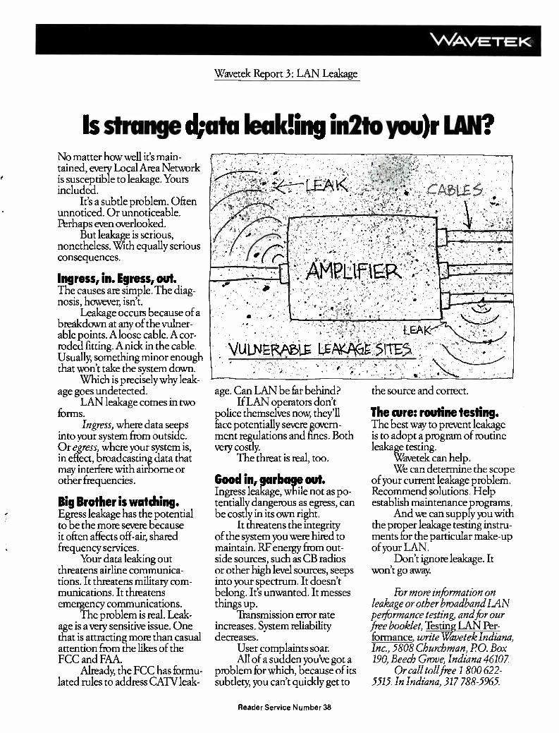
VvArve-T-K,
Wavetek Report 3: LAN Leakage
Is strange *ata leakling in2to you)r No matter how well it's main-tained, every Local Area Network is susceptible to leakage. Yours included.
It's a subtle problem. Often unnoticed. Or unnoticeable. Perhaps even overlooked.
But leakage is serious, nonetheless. With equally serious consequences.
Ingress, in. Egress, out. The causes are simple. The diag-nosis, however, isn't.
Leakage occurs because of a breakdown at any of the vulner-able points. A loose cable. A cor-roded fitting. A nick in the cable. Usually, something minor enough that won't take the system down.
Which is precisely why leak-age goes undetected.
LAN leakage comes in two forms.
Ingress, where data seeps into your system from outside. Or egress, where your system is, in effect, broadcasting data that may interfere with airborne or other frequencies.
Big Brother is watching. Egress leakage has the potential to be the more severe because it often affects off-air, shared frequency services.
Your data leaking out threatens airline communica-tions. It threatens military com-munications. It threatens emergency communications.
The problem is real. Leak-age is a very sensitive issue. One that is attracting more than casual attention from the likes of the FCC and FAA.
Already, the FCC has formu-lated rules to address CATV leak-
the source and correct. age. Can LAN be far behind? If LAN operators don't
police themselves now, they'll face potentially severe govern-ment regulations and fines. Both very costly.
The threat is real, too.
Good in, garbage out. Ingress leakage, while not as po-tentially dangerous as egress, can be costly in its own right.
It threatens the integrity of the system you were hired to maintain. RF energy from out-side sources, such as CB radios or other high level sources, seeps into your spectrum. It doesn't belong. It's unwanted. It messes things up.
Transmission error rate increases. System reliability decreases.
User complaints soar. All of a sudden you've got a
problem for which, because of its subtlety, you can't quiddy get to
The cure: routine testing. The best way to prevent leakage is to adopt a program of routine leakage testing.
Wavetek can help. We can determine the scope
of your current leakage problem. Recommend solutions. Help establish maintenance programs.
And we can supply you with the proper leakage testing instru-ments for the particular make-up of your LAN.
Don't ignore leakage. It won't go away
For more information on leakage or other broadband LAN performance testing, and hr our free booklet, Testing LAN Per-formance write Wavetek Indiana, Inc., 5808 Churchman, PO. Box 190, Beech Grove, Indiana 46107.
Or call toll free 1 800 622-5515. In Indiana, 317 788-5965.
Reader Service Number 38

LAN
Some companies are developing new hardware to serve the needs of business
data users.
send the best talent you've got. Too, the physical environment can be quite different: I-beams; electrical surges; pulls through chemically volatile work areas, and high RFI and EMI from large machines. Amplifiers will need to
hide in closets or plenums, splices will have to be tight. To get a grip on the business will
take some work. One vendor routinely calls reporters who do stories in com-munications trades on companies get-
LRC ELECTRONICS INTRODUCES SELF-TERMINATING CABLE CONNECTORS
LRC's self-terminating coaxial cable connector is designed for the automatic termination of a 75 ohm coaxial transmission line in a coaxial cable system when a cable/connector inter-face is interrupted.
FEATURES: 1) Automatic termination when
interface is disconnected. 2) Quality workmanship and
material, insuring long life and unlimited disconnects.
3) Components completely contained in housing to in-sure highest RF integrity.
4) Elimination of ingress and egress problems from un-terminated ports.
5) Compact design for compat-ibility in any application.
6) Compatible with RG 59 U and RG 6U connectors for both PVC and plenum cables.
7) Eliminates chains and loose terminators which are mis-placed or not re-connected.
8) "D" flat installation to pre-vent rotation.
SPECIFICATIONS: 1) Structural 18 db 0-450
Return Loss MHz
2) Insertion loss .2 db
3) RF shielding effectiveness
<-60 db (reduces signal 1/millionth of the voltage)
4) Material Brass (main body)
5) Plating Bright nickel (main body)
6) Contacts Silver-Plated
AUGAT ¿RC Quality and Innovation
LRC Electronics, Inc. 901 South Avenue Box 111, Horseheads, NY 14845 (607) 739-3844
Reader Service Number 39
ting LANs. Others read Commerce Business Daily. And a new stack of reading material is essential. Some read telephone or data processing trades. Others favor the slew of publi-cations with the name "Communica-tion" someplace on the masthead. Vis-its to LocalNet, Communications Net-works and Interface trade shows also are considered "musts" by experi-enced players. The LAN business also is seasonal,
partly because construction schedules favor the better weather, more impor-tantly because there's a lag between the start and end of a procurement and purchasing cycle. That can take a while. Keep in mind, too, that once all clearances are given, the customer will likely want delivery within 30 days. That can be next to impossible to com-ply with. But there are lots of land mines wait-
ing out there. For one thing, it's a busi-ness that takes more technical sophis-tication than some companies are used to. And even when you've got the knowledge of data communications, there are some jobs you don't want. "You can get over your head and get burned very easily," says one knowl-edgeable observer. You have to know when you don't have enough informa-tion or skills to proceed with a bid." Adds another observer: "Some compa-nies already have done themselves some harm by not knowing what they were doing." To avoid those kinds of dangers, RT/Katek's LAN/stall divi-sion, for example, has a policy of only sending the better personnel from its construction and installer groups.
In some cases, companies are devel-oping new types of hardware to serve the needs of the business data user. Augat's LRC division, for example, has developed a self-terminating connector that is unique at the mo-ment. Because it automatically termi-nates whenever the interface is discon-nected, ingress and egress problems growing from unterminated ports are eliminated. The unit withstands unlim-ited disconnects, an important consid-eration when devices are frequently moved from port to port. Also, all com-ponents are held inside the main hous-ing, improving RF integrity. Factory networks are a special case
in point. Downtime in a manufacturing
64 Communications Engineering and Design August 1986
Status monitoring in CATV has come to mean modules plugged into trunk amps.
setting can run up to $6,000 a minute, so rapid fault isolation is critical. Typi-cally, CATV status monitoring sys-tems have been located only in trunk amplifiers. That helps, but not so much as a system that monitors all active devices on the system, from headend to drop. Also, it isn't enough to moni-tor one frequency alone, such as a pilot carrier. A system to monitor the entire bandwidth of the system is better. Hot standbys are one way to backup a sys-tem, especially if the cut-over is exe-cuted automatically. Not many CATV-type monitoring systems have this ability however. Component redun-dancy also helps. What's nice, though, is to get immediate notice when a pri-mary unit has failed and the backup has kicked in.
Status monitoring Traditionally, status monitoring in
CATV has come to mean modules plugged in to trunk amps. Typically, a single frequency is monitored in each direction, and information is gathered on return feeder attenuation, cutoff, power supply and battery status, volt-age level, temperature, load or charger status. That's good, but is limited by the total number of monitoring sta-tions on the network. The Network Technologies division of AM Cable, though, seems to have come up with a better mousetrap, especially for down-time-sensitive factory automation ap-plications. The company soon will be distributing its new TMC-8000 Techni-cal Monitor and Control System, which has some interesting abilities.
It monitors multiple pilot carriers in both directions: headend to end-of-drop as well as end-of-drop returning to the headend. As many as 250 re-mote sensing units connected to the network are automatically interro-gated, identified and tracked once at-tached—no operator intervention is required. Additionally, the TMC-8000 automatically reports on the location and signal frequency of any measure-ment outside operator-configured pa-rameters.
Here's another nice feature. The sys-tem is user-programmable as far as level readings. You can poll any fre-quencies from 40 to 400 MHz in 50 kHz increments. An intelligent A-B switch is under development that will
be located at the end of certain critical drops. It will switch from A to B cable or vice versa in case of complete cable failure or failure in only a single direc-tion on either cable. Now focusing primarily on design,
construction and certification of net-works, Network Technologies hopes to use the TMC-8000 to develop mainte-nance agreements on a wide scale. The company also would like to OEM the product and is in discussions about that now. To round out the product, the firm is completing work on inter-faces that will monitor vital signs on various makes of amplifiers, focusing on three popular lines at first. C-COR, meanwhile, remains a leader
in the broadband LAN market, and first recognized the potential about five years ago. It began then to de-velop specific amplifiers and other products just for LANs. It also began doing system design and proofs, and like other manufacturers, finds the end user business much smaller than the system integrator market. End users are about 20 percent of the company's business, says Dick Faulkner, regional account executive. At the moment, C-COR probably holds about 50 percent of the entire market in its lines of busi-ness, built on a reputation for reliabil-ity. In fact, MTBF figures for com-pany actives are in excess of 500,000 hours. Faulkner says some recent stud-ies indicate something more on the or-der of 57 years in some cases.
In addition to its amplifiers and translators, the company also has come out with telemetry packages and an intelligent A-B switch that auto-matically routes signals in systems with redundant cable paths, whether single or dual-cable. Wavetek Indiana finds that its
CATV-type products need more tai-lored offsets and closer alignment to meet the needs of the LAN market. The company also has worked to make cosmetic adjustments so its products look like they belong in a lab-type set-ting. But the basic performance is much the same. Wavetek guesses that LAN business could be as big as its CATV business within the next five years. Comsonics also has been busy sell-
ing products like the Sniffer in LAN Continued on page 84
When you made your decision on LAN hardware, did you also consider who would be doing the contract labor for your system design and installation?
Our track record in design, construction and installation of both franchised and private cable systems is a logical back up for giving your LAN system the same proven performance.
If you didn't your system may well not deliver the results you're seeking. That's why we'd like you to consider contacting us or having your supplier contact us.
CATV Subscriber Services, Inc.
When you need contract services, you want results. CSS delivers.
108 State Street Suite 102 Greensboro, NC 27408 919-273-5553 (in NC) 800-334-0860
Reader Service Number 40
Communications Engineering and Design August 1986 65

Optical fiber moving into new world
Fiberoptic applications are rapidly growing in number as the use of the technology moves from con-
centration in long-distance telecom-munications into local environments. The initial benefits of optical fiber
made it irresistible as a replacement for copper media for handling the enor-mous distances and amounts of infor-mation traveling across the country or even around the world. And these ap-plications will continue. But optical fiber is becoming the
media of choice for other sorts of appli-cations, including transmission be-tween and within buildings, from ma-chine to machine, in networks, and even within a single piece of equip-ment. These new applications are leading
to a wide range of new hardware de-signed to meet the needs of local opti-cal transmission. Long-distance fiber-optic transmission has moved toward a set of components optimized for that particular area—single-mode fiber, la-ser diode transmitters, APD receivers, and operation at 1300 nm or 1550 nm wavelength. Just as the copper world has found
that there is no universal solution (coax is not used everywhere), the opti-cal world is moving into a set of differ-ent components optimized for the de-veloping local environment. Key reasons for the adoption of fiber
in these environments, aside from its superb attenuation characteristics, stem from its high data rate capability, electromagnetic immunity, ground-loop elimination, security, small size and expansion capability. The last factor is becoming increas-
ingly important, as users are empha-sizing investments in technology that will wear well in the future and not be outdated before being put into opera-tion. Most of today's applications are limited more by the electronic capabili-ties at the ends of the fiber than the fi-ber itself. A major advantage in using fiber
technology is that future improve-ments will involve changing the elec-tronics only and not the fiber itself. Today's installed fiber will undoubt-edly serve applications for many years
New optical fiber applications are leading to a wide range of new hardware to meet the needs of local optical
transmission.
Robert K Southard, AMP Incorporated
in the future. This paper concerns the design of fi-
beroptic systems. Information on a wide variety of materials for fiberoptic installations are detailed in AMP's OPTIMATE Fiberoptic Interconnec-tion System (Catalog 83-718). Since the catalog also contains an introduction to basic system components, this infor-mation will not be repeated here.
System specification
In some instances, fiber will be used to replace copper. The system architec-ture will already be defined, and the system specification will be aimed at duplicating or enhancing the existing system performance.
In other cases, totally new applica-tions will face the challenge of taking maximum advantage of optical tech-nology. In either case, this paper will aid in the decision-making needed to define, design, and evaluate a fiberop-tic system properly. System architecture will address
such issues as making the best trade-offs between transmission system per-formance and system complexity. Since digital systems ultimately deal with parallel data, decisions will need to be made regarding the degree of multiplexing to be implemented vs. the number of fiber channels to be used. In some cases, the use of slower parallel optical channels will save sufficient cir-cuitry to justify their implementation. Some situations may entail the need
to transmit data in relatively infre-quent high-data-rate bursts. Tradeoffs must be made on the use of more com-plex circuitry to buffer the data vs. a simpler approach that uses a higher speed optical link that will operate without buffering. After system-architecture concepts
are evaluated, a data rate for the opti-cal channel will be established. Meth-ods for encoding the data will need to
be evaluated. Factors that enter into the selection of a code including adding redundancy to the signal to enhance error-free detection, enriching the data stream to ensure a minimum data re-quired by the optical link, constraining the duty cycle of the signal as required by the optical receiver, and including sufficient transitions to allow clock re-covery and synchronization. The simplest of these, such as NRZ,
may be ideal for the application, while more complex codes might be required for the additional features that they provide. The choice of a particular code can
be quite significant to transmission system specifications. For example, a signal with a 20-Mb/s data rate that is encoded by one of the relatively sim-ple-to-implement bi-phase codes will require a link with twice this capacity in bits per second—the same capacity as a link carrying a 40-Mb/s signal us-ing NRZ code. Each bit of data re-quires up to two signal symbols, which effectively doubles the bandwidth re-quirements on the transmitter, re-ceiver, and fiber in the system. Other codes are employed that treat
a number of data bits as a set, and en-code these bits with a slightly larger number of bits. These so-called group or block codes are specified as mB/nB codes, where m data bits are encoded into n bits for transmission. Common types of group codes are
the 1B/2B codes, such as the bi-phase code mentioned above, 3B/4B, 4B/5B and 8B/10B. These codes serve many of the desir-
able functions mentioned above, yet increase channel capacity require-ments only fractionally. This is typi-cally done at the cost of more complex coding circuitry, however.
Additional concerns
An additional concern in establish-ing a system specification is the deter-mination of the distance required of the optical channel. Both the maxi-mum and the minimum should be es-tablished. A strategy could also be evaluated that would allow lengths longer than some maximum length, but with degraded performance. Appli-cations may present themselves that require this longer length, but do not
66 Communications Engineering and Design August 1986

Ir '
Rest easy,
you can sleep
tonight...
YOUR BROADBAND NETWORK IS UNDER CONTROL
Of Network Technologies TMC-8000M
You can lose a lot of sleep worrying about all of that expensive machinery and computing power tied into one broadband network.
Until now.
Network Technologies introduces the Technical Monitor and Control System, Model TMC-8000. Now, for the first time, you can rest easy — the TMC-8000 will babysit your broadband network. Furthermore, it will take continuous measure-ments of downstream and upstream frequency response, at every node in the system (not just in active line equipment and power supplies), with a measurement resolution of ± 0.5 dB at any frequency in the system between 40 and 400 MHz, on single and dual cable systems.
Not only that, it will set an alarm if any response parameters exceed preset limits that you select, and it will tell you the exact location of any failure. All at a cost that will easily satisfy your budget.
Network Technologies is more than just state-of-the-art network products—it's also one of the leading full-service broadband network design and construction firms in the business. From system definition and headend design, to cable installation and proof-of-performance testing, to complete in-plant training, Net-Tech' can and does do it all.
Call us now at 215-536-1354 for specifications and information on applications that will suit your needs.
A DIVISION OF AM CABLE TV INDUSTRIES, INC. P.O. Box 505. Quakertown, PA 18951 (215) 536-1354 Telex 510-651-0060
Reader Service Number 41

FIBER OPTIC DESIGN
The fiber of choice for local applications is
unquestionably multimode fiber.
have the throughput or accuracy re-quirements of the bulk of the applica-tions.
In these cases, engineering analysis may indicate that a particular optical transmission system will provide this capability with no additional redesign. The error-rate performance of the
communication system also must be factored in. A realistic estimate should be placed on the bit-error rate (BER) that can be tolerated in the transmis-sion path, while retaining the ability of the overall system to meet its specifi-cations. A transmission path carrying voice
or video information will most likely have a very different BER requirement than with a path carrying computer data. Stringent requirements may ne-cessitate additional levels of data en-coding, such as the use of error-correcting codes.
Higher-level system protocols may also be employed, such as cyclic redun-dancy checks, to monitor errors, fol-lowed by requests for retransmission when errors are detected. All these fac-tors should be considered before estab-lishing a BER performance require-ment for the optical link under design. The goal of system design is to use
the system specification to produce a detailed layout and list of the specific components that operate together to satisfy the specifications. The many variables involved include choice of operating wavelength; type of fiber, emitter, and detector; and selection of specific transmitters, receivers, cables, connectors, and other components. Ar-riving at the best solution will involve
a number of initial assumptions and choices, as well as analysis and evalua-tion of tradeoffs. Many local fiberoptic applications
will be best met by operation in the 800 nm to 900 nm optical wavelength win-dow. Very good performance and rela-tively inexpensive components are available for these applications. Evalu-ating system performance in this wavelength range would be a reason-able approach, unless other informa-tion has already proven the need to move to other wavelengths. The fiber of choice for local applica-
tions is unquestionably multimode fi-ber. This fiber allows the use of rela-tively simple and inexpensive LED emitters and PIN diode detectors. Multimode fiber will provide good at-tenuation and bandwidth performance in the 850 nm wavelength range and even better performance in the 1300 nm range. Next, the system specifications are
used to determine which transmitters and receivers are appropriate, based on signal characteristics such as data rate, duty cycle, and so forth. In some cases, a transmitter or receiver will be close to meeting the defined needs, but may have excess capability in some areas, and insufficient capability in others. For example, an application might
require 100-Mb/s transmission with a given power budget and with a BER of 10-9. A receiver specified at 100-Mb/s and a BER of 10.12 may operate prop-erly due to the tradeoff between data rate and bit-error rate. Information on these tradeoffs, as discussed later, and
engineering analysis will be needed to resolve these issues.
After these initial decisions have been made, system design turns to the analysis of establishing signal integ-rity through the fiber system. Evalua-tion of link performance is carried out in two main areas—optical power and bandwidth. The design will need to proceed
along both lines, with the interactions between the two areas continuously examined.
Power budget
The key elements in a simple power analysis of a fiberoptic link (transmit-ter, fiber, and receiver) are: • transmitter power put, into a spe-
cific fiber, Pr • fiber attenuation per unit length,
AL • receiver sensitivity or minimum
input power, PR • connector and component loss in
the fiber path, Ae • link margin, M The typical process of working
through a power budget involves mak-ing initial selections of potential com-ponents for the link and then proceed-ing with the power calculations. Ex-pressing the loss and link margin values in dB and power values in dBm, the basic formula is:
M = Pr — AL • L—Ae — PR
where L is the length of fiber in the system. Multiple fiber segments are simply combined algebraically.
DATA
CLOCK
NW!.
E 1 •
-1111 re BIT PERIOD
10101011101011 1 1011111 1 1
Fi Li I Ljuij
1111 iLiinJ
Rz I I 1 I I I
NR!.!
MANCHESTER I
MILLER
BIPHASE-m I
I I
, Format
FIGUR
Symbols Se • - Duty Factor Per §16asalgoe.- -.AMU -
' NRZ 1 No 0-100
RZ IMF
NRZI 1 No
2 4111141•111111 0-100
Manchester (Biphase-1)
Yes 33-67
Biphase-m (Bifrequency) 2 Yes
68 Communications Engineering and Design August 1986

FIBER OPTIC DESIGN
Values for connector loss, fiber attenuation and length can be used to determine the
margin of the system.
The transmitter power and receiver sensitivity are taken from the appro-priate data sheet, typically in units of dBm. Normally, peak power values are used throughout the calculation. This is based on a 50 percent duty-
cycle signal, so that average power is one-half of peak power. That is, aver-age power is 3 dB below peak power. Any inconsistency here will cause
sizeable errors to occur. All AMP spec-ifications are in peak power. Values for connector loss, fiber at-
tenuation, and length can be used along with the information on the transmitter and receiver to determine the margin of the system. Acceptable limits for margin are highly dependent upon the application. Links that are put into service with no changes ex-pected in the future may require rela-tively little margin. On the other hand, links that are ex-
pected to be extended in distance or to receive additional connectors and com-ponents will need appreciably more margin in anticipation of this addi-tional attenuation. Consider an example typical of local
area networks. An 85 ,um core fiber is initially selected for analysis. A 100-Mb/s transmitter/receiver pair is se-lected based on data rate. Data-sheet information indicates a launched power of —16 dBm for the selected fi-ber, while receiver sensitivity is given as —30 dBm worst-case. Connector loss is expected to be 1.5 dB maximum per matched pair with up to two connector pairs anticipated in the link. An estimate of the required margin is made—for example, 5 dB for compo-nent aging and possible link repairs and extensions.
Rearranging the above formula and calculating the total allowable fiber loss gives:
A, • L = —16 dBm — 2 • 1.5 dB —
(-30 dBm) — 5 dB, = 6 dB
Selecting a fiberoptic cable that has an attenuation of 5 dB/km will then al-low a link length of 1.2 km, based on power budgeting.
Fine-tuning
The previous analysis is a much sim-
plified approach, although very useful. More precise calculations involve the realities of dealing with an optical fiber as an electromagnetic waveguide whose properties are extremely com-plex.
In addition, most component specifi-cations are themselves simplifications. Although it is not possible to treat these subjects fully here, some addi-tional discussion will aid system de-sign.
PAY TV can be a profitable experience for Hotels, Hospitals, Apartments and Cable TV systems. With flexible Triple Crown equipment for building wiring of all types, be it Loop-Thru wall plates, off premise Home Run taps, or impulse two way interactive convertors, Pay Television could generate an impressive extra income for you.
Pay per view, per day or per stay, with options from call down manual ordering, touch tone automatic, impulse full convertor, we offer the correct system for your needs. Triple Crown addressables also offer remote access by your office business computer via cable or phone modem through the area processor which constantly refreshes the system. We can even save you money through the use of remote control disconnects.
To get a clearer view of the many ways Triple Crown addressables can make PAY TV more profitable for you, call us first, because we are!
-410 tiw TRIPLE CROWN q:.• ELECTRONICS 4560 Fieldgate Drive • 601 Fairway Dr. Mississauga, Ontario L4W 3W6 Deerfield Beach, Florida 33442 (416) 629-1111 Reader Service Number 42 (305) 429-087011-800-824-4332
Communications Engineering and Design August 1986 69
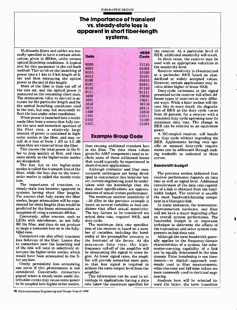
FIBER OPTIC DESIGN
The importance of transient vs. steady-state loss is
apparent in short fiber-length systems.
Multimode fibers and cables are nor-mally specified to have a certain atten-uation, given in dB/km, under certain optical launching conditions. A typical test for this parameter is the cut-back method. This involves the launching of power into a 1 km to 3 km length of fi-ber and then measuring the optical power at the end of this length. Most of the fiber is then cut off of
the test set, and the optical power is measured on the remaining short stub. The attenuation value so derived is ac-curate for the particular length and for the optical launching conditions used in the test, but may not accurately re-flect the loss under other conditions. When power is launched into a multi-
mode fiber from a source that fully cov-ers the area and numerical aperture of the fiber core, a relatively large amount of power is contained in high-order modes in the fiber, and may re-sult in a loss of from 1 dB to 1.5 dB when they are removed from the fiber. This causes the total power in the fi-
ber to drop quickly at first, and then more slowly as the higher-order modes are dissipated. The loss due to the higher-order
modes is called the transient loss of the fiber, while the loss due to the lower-order modes is called the steady-state loss. The importance of transient vs.
steady-state loss becomes apparent in systems having short fiber lengths. For sources that fully excite the fiber modes, larger attenuation will be expe-rienced for short lengths than would be predicted by the linear attenuation as-sumption of using a constant dB/km. Conversely, other sources, such as
LEDs with microlenses, do not fully fill the fiber, and thus do not produce as large a transient loss as in the fully-filled case. Connectors can also affect transient
loss behavior of the fiber. Losses due to connectors near the launching end of the link will tend to selectively at-tenuate the higher-order modes, which would have been attenuated in the fi-ber anyhow. Overly pessimistic loss accounting
can occur if this phenomenon is not considered. Conversely, connectors placed where a steady-state mode dis-tribution exists may cause some power to be coupled into higher-order modes,
Data
0000 0001 0010 0011 0100 0101 0110 0111 1000 1001 1010 1011 1100 1101 1110 1111
4B/5B Code
11110 01001 10100 10101 01010 01011 01110 01111 10010 10011 10110 10111 11010 11011 11100 11101
Example Group Code
thus causing additional transient loss in the fiber. The data sheet values given for AMP components tend to in-clude some of these additional losses that would typically be experienced in short-distance applications. Although connector and fiber mea-
surement techniques are being devel-oped to characterize this behavior bet-ter, current engineering must be under-taken with the knowledge that the data sheet specifications are approxi-mations of actual system performance. The minimum receiver sensitivity of
—30 dBm in the previous example is based on several variables or test con-ditions that affect actual sensitivity. The key factors to be considered are actual data rate, required BER, and duty cycle. The maximum data rate specifica-
tion of the receiver is based on a num-ber of variables, including the band-width of the preamplifier circuitry in the front-end of the device. At the maximum data rate, the high-frequency roll-off of the amplifier will be attenuating the signal to some de-gree. At lower signal rates, the ampli-fier will provide somewhat more gain, so that less signal is required to achieve the same output level from the amplifier. This information can be used to ad-
vantage in applications having a data rate below the maximum specified for
the receiver. At a particular level of BER, additional sensitivity will result.
In these cases, the receiver may be used with an appropriate reduction in the sensitivity level.
Receiver sensitivity is characterized at a particular BER based on stan-dardized or widely accepted values. However, certain applications may in-volve either higher or lower BER.
Duty-cycle variations in the signal presented to the receiver will affect dif-ferent types of receivers in very differ-ent ways. While a later section will dis-cuss this in more detail, the degrada-tion of BER as the duty cycle varies from 50 percent, for a receiver with a restricted duty cycle operating near its maximum data rate. The change in BER can be referred to an equivalent power. A DC-coupled receiver, will handle
any duty cycle without degrading the BER. Applications having very spe-cific or unusual duty-cycle require-ments can be addressed through mak-ing tradeoffs as indicated in these curves.
Bandwidth budget
The previous section indicated that receiver performance depends on data rate as well as signal level. Additional consideration of the data rate capabil-ity of a link is obtained from the band-width budget. The receiver is usually the most bandwidth-limiting compo-nent in a fiberoptic link.
In many instances, the transmitter, interconnection hardware, and fiber will not have a major degrading effect on overall system performance. The bandwidth budget is an important technique to determine the effects of the transmitter and other system com-ponents on link data rate. Although the term bandwidth gener-
ally applies to the frequency-domain characteristics of a system, the infor-mation-carrying capability of a link can be equally determined in the time domain. Pulse broadening is one time-domain—or digital—approach com-monly used in fiber measurements, while rise-time and fall-time values are more commonly used in electrical engi-neering. Analysis here will be oriented to-
ward the latter; the term transition
70 Communications Engineering and Design August 1986
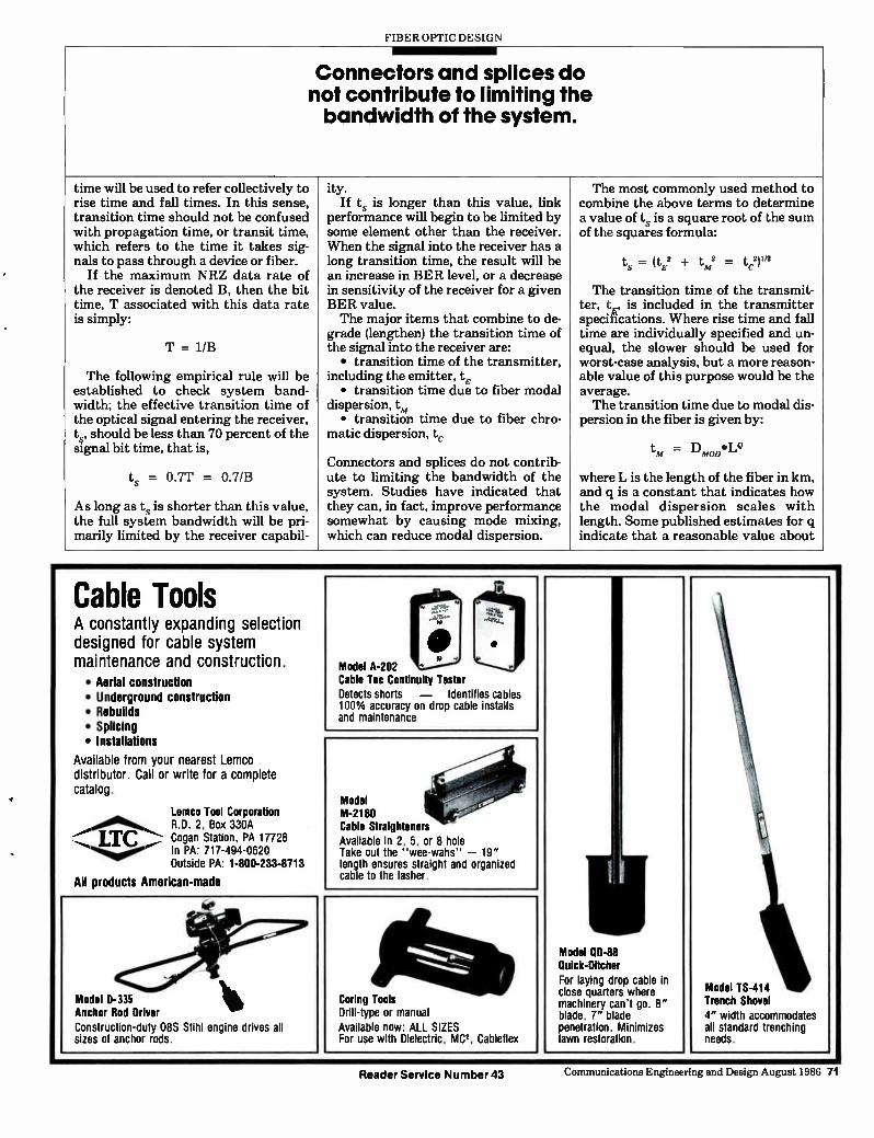
FIBER OPTIC DESIGN
Connectors and splices do not contribute to limiting the bandwidth of the system.
time will be used to refer collectively to ity. The most commonly used method to rise time and fall times. In this sense, transition time should not be confused
If ts is longer than this value, link performance will begin to be limited by
combine the above terms to determine a value of ts is a square root of the sum
with propagation time, or transit time, some element other than the receiver, of the squares formula: which refers to the time it takes sig- When the signal into the receiver has a nals to pass through a device or fiber. long transition time, the result will be ts = (tp2 + tm2 = tc.2)"2
If the maximum NRZ data rate of an increase in BER level, or a decrease the receiver is denoted B, then the bit in sensitivity of the receiver for a given The transition time of the transmit-time, T associated with this data rate is simply:
BER value, The major items that combine to de-
ter, t„, is included in the transmitter specifications. Where rise time and fall
grade (lengthen) the transition time of time are individually specified and un-T = 1/B the signal into the receiver are: equal, the slower should be used for
The following empirical rule will be • transition time of the transmitter,
including the emitter, tE worst-case analysis, but a more reason-able value of this purpose would be the
established to check system band- • transition time due to fiber modal average. width; the effective transition time of dispersion, tm The transition time due to modal dis-the optical signal entering the receiver, • transition time due to fiber chro- persion in the fiber is given by: t, should be less than 70 percent of the signal bit time, that is,
matic dispersion, t,
Connectors and splices do not contrib-tm = Dmo„•LQ
ts = 0.7T = 0.7/B ute to limiting the bandwidth of the system. Studies have indicated that
where L is the length of the fiber in km, and q is a constant that indicates how
As long as ts is shorter than this value, the full system bandwidth will be pri- manly limited by the receiver capabil-
they can, in fact, improve performance somewhat by causing mode mixing, which can reduce modal dispersion.
the modal dispersion scales with length. Some published estimates for q indicate that a reasonable value about
Cable Tools A constantly expanding selection designed for cable system maintenance and construction. • Aerial construction • Underground construction • Rebuilds • Splicing
M 1.-.
Model A-202 Cable Tec Continuity Tester Detects shorts — Identifies 100% accuracy on drop cable and maintenance
Nee., .5.1 .e ...
•
cables installs
• Installations
Available from your nearest Lemco distributor. Call or write for a complete catalog.
Lemco Tool Corporation R.D. 2, Box 330A
LTC Cogan Station, PA 17728 In PA: 717-494-0620 Outside PA: 1-800-233-8713
All products American-made
— - Model M-2180 Cable Straighteners Available in 2, 5, or 8 hole Take out the "wee-wahs" — 19" length ensures straight and organized cable to the lasher.
e -•
- .
Model D-335 Anchor Rod Driver Construction-duty 08S Stihl engine drives all sizes of anchor rods.
Coring Tools Drill-type or manual Available now: ALL SIZES For use with Dielectric, MC', Cableflex
Model OD-88 Quick-Ditcher For laying drop cable in close quarters where machinery can't go. 8" blade, 7" blade penetration. Minimizes lawn restoration.
Model TS-414 Trench Shovel 4" width accommodates all standard trenching needs.
--...„
Reader Service Number 43 Communications Engineer'ng and Design August 1986 71

FIBER OPTIC DESIGN
Chromatic dispersion is due to the material and
waveguide properties of the fiber.
0.7, but this value applies primarily to very long fiber systems. Other estimates for q place its value
for short system at approximately 1. 13,,,,D is a value that indicates the amount of modal dispersion due a par-
ticular fiber. Since the above function is nonlinear with length, it is impor-tant that a value for Dmo, in units of ns/km, be obtained with a fiber length of 1 km, or at least at some known length.
When they put you in charge of opera-tions for a cable system of 185,000 subscri-bers, you're faced with a lot of tough decisions.
Frank DeJoy, Vice President of Operations of Suburban Cable in East Orange, New Jersey can testify to that. He and his staff took a year and a half to study all the problems and considerations of addressabil-ity for a system as large as Suburban's. When they finally made their choice, it
was Sigma. "It offers security we'll be able to rely on for the next ten years," DeJoy explains, "and technically, it is far superior to anything else we looked at."
But technology wasn't the only reason DeJoy chose Sigma. "I like the cooperation
and support of the Oak organization," and later added, "Oak engineers worked with us to develop an electronic second set rela-tionship which allows the converter of the primary set to authorize the secondary set converter to function." Oak solved a dilemma for Frank DeJoy
and Suburban Cable. And in the process, developed a technology that is now a stan-dard part of Oak's Sigma converter-decoder.
If you'd like more information concerning Sigma, call your nearest Oak representative or contact us directly at (619) 451-1500.
We'll save you a fortune on cable theft. And speaking from a Frank point of view, we'll also save you a year and a half of your time.
Oak Communications Inc 16516 Via Esionlla Rancho Bernardo. CA 92127 (619) 451-1500 0 OAK COMMUNICATIONS INC
Reader Service Number 44
If a value of Dmo, iS not available, the best estimate for modal dispersion is based on the bandwidth specifica-tion for the fiber, B r Estimates for the resulting transition time are obtained from
tm = 0.44 LQ/13,.
Since transition time, and thus band-width, may not scale linearly with length, it is clear that specifying band-width, Bi., is specified in units of MHz.km is not a precise indication of actual performance.
It is accepted commercial practice to publish fiber bandwidth in MHz.km, however, without indicating the test conditions or length employed for the specification. These bandwidth values can be used with the knowledge that they are only valid if obtained on a 1 km length.
If it is known that the bandwidth was obtained with some other fiber length, Lo, then transition time due to modal dispersion is given by:
tm = 0.44/13p • (L/L0)Q
Thus, as an example, given a fiber bandwidth of 200 MHz.km (obtained at 1 km), a fiber length of 300 m, and using q = 1, we have
t = (0.44)(.3 km)/
(200 MHz.km) = 0.66 ns
Chromatic dispersion is due to the material and waveguide properties of the fiber. For multimode fiber in the 800 nm to 900 nm wavelength range, wave-guide dispersion can be ne-glected. In this wavelength range, common glass fibers have a material dispersion, D., Values for D „ 17. in the literature are
sometimes shown as positive and sometimes negative. A positive value is required for the calculations that fol-low.
= D mAT • X • L
where X is the spectral width of the source. For an LED transmitter with a 50 nm spectral width and 300 m of fi-ber having a material dispersion of 0.1 ns/nm/km, the calculation is
72 Communications Engineering and Design August 1986

FIBER OPTIC DESIGN
If improved optical signal transition time is desired, a faster transmitter is one item
to consider.
= (0.1 ns/nm/km)(50 nm)
(.3 km) = 1.5 ns
Due to the relatively large spectral width of LEDs compared to laser diodes, material dispersion in LED systems operating in the range of 850 nm will often be more limiting than modal dispersion. At 1300 nm, the situation is more
complex, since material dispersion is very low. In this case, wavelength dis-persion should be considered, and an accurate value of modal dispersion will be quite important. With the above information, the op-
tical transition time into the receiver, ts, can now be estimated. Assuming that the transmitter transition time, tb,, is about 4 ns, and using the above examples,
= (42 + .672 4. 1.62)1/2 = 4.3 ns
For a 50-Mb/s receiver, the permitted transition time into the receiver is given by:
0.7/B + 14 ns
Thus, the calculation indicates that receiver performance would not be de-graded at 50 Mb/s for the values cho-sen. The above equations can be used to determine the maximum fiber length that could be used in this exam-ple before ts would exceed the specified limit, and thus degrade system perfor-mance. This calculation indicates a maximum length of about 2.5 km.
If t, exceeds the limit indicated above,. the optical transition time will cause receiver performance to be some-what less than optimum. This may be acceptable, particularly if the link is being operated at a data rate lower than the maximum rate specified for the receiver.
In this case, the reduced receiver performance due to slow optical transi-tion times will be offset by the in-creased sensitivity due to the lower data rate. In general, receiver perfor-mance may be quite acceptable in such a case, due to other margins in the de-sign.
If improvement in the optical signal transition time is desired, a faster
transmitter would be one item to con-sider. A final word of warning is in order.
The calculations made above involve a large number of approximations and empirical estimations. In situations
that are borderline in nature, more ex-acting measurements will have to be made. Performance measurements on actual components, including both power and BER studies, will be needed to confirm actual system capability.
„Looking into the1000series.,
IS LIKE LOOKING INTO
THE FUTURE! WITH THE LINDSAY 1000 SERIES TRUNK, YOU CAN START WITH AN
OPEN RETURN SYSTEM & MULTIPLEX WHEN YOUR SUBSCRIBER BASE HAS EXPANDED, BY SIMPLY ADDING MODULES. BY MULTIPLEXING, THE LINDSAY 1000 SERIES CAN ACCOMMODATE UP TO 400 CONTINUOUSLY TRANSMITTING HOME TERMINAL UNITS, PER BRIDGER STATION. THE SYSTEM ALSO FEATURES FAILSAFE FORWARD & REVERSE STATION BYPASS, POWER DOUBLING & FEED FORWARD, AS WELL AS DIAGNOSTIC CAPABILITIES.
SPECIALTY PRODUCTS LIMITED
50 MARY ST. W. LINDSAY, ONTARIO CANADA K9V 4S7 TEL. 705-324-2196
CAL: TELEWIRE SUPPLY 415-939-9243 COL: ADVANCED COMM. 303-596-4464 FL: TELEWIRE SUPPLY 800-237-8203 NY: TELEWIRE SUPPLY 800-645-9510 OH: THE HEAD END 614-766-0874 PA: TONER CABLE EQUIP 215-675-2053 TX: TELEWIRE SUPPLY 800-527-1646
Reader Service Number 45
Communications Engineering and Design August 1986 73
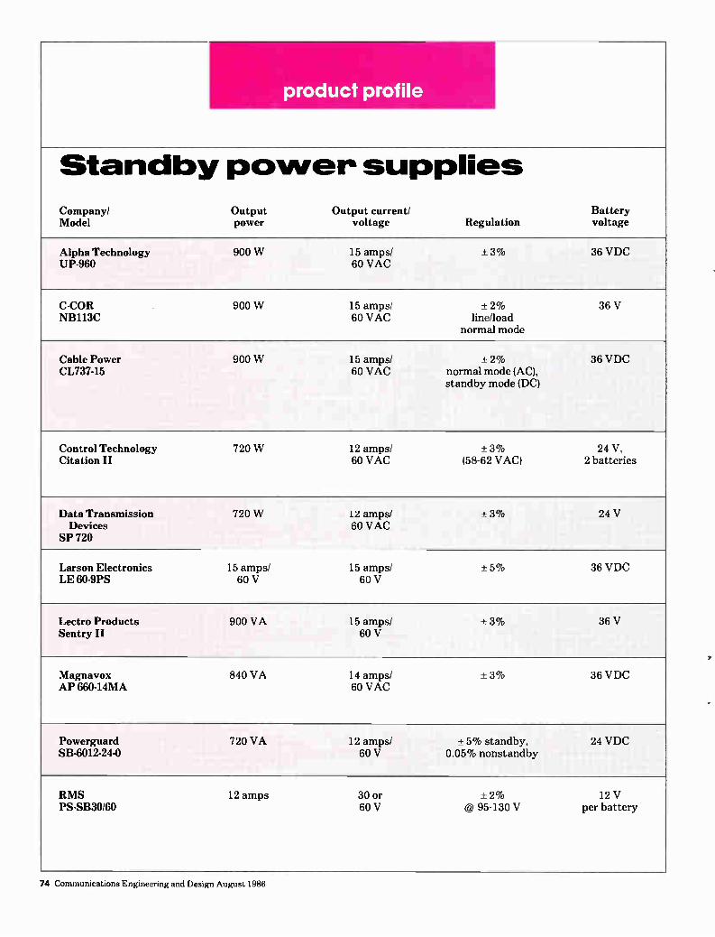
product profile
Standby power supplies
Company/ Output Output current/ Model power voltage Regulation
Battery voltage
Alpha Technology UP-960
900 W 15 amps/ 60 VAC
± 3% 36 VDC
C-COR NB113C
900 W 15 amps/ 60 VAC
± 2% line/load
normal mode
36 V
Cable Power CL737-15
900 W 15 amps/ 60 VAC
+ 2% normal mode (AC), standby mode (DC)
36 VDC
Control Technology Citation II
720 W 12 amps/ 60 VAC
+ 3% (58-62 VAC)
24 V, 2 batteries
Data Transmission Devices
SP 720
720 W 12 amps/ 60 VAC
± 3% 24 V
Larson Electronics LE 60-9PS
15 amps/ 60 V
15 amps/ 60 V
± 5% 36 VDC
Lectro Products Sentry II
900 VA 15 amps/ 60 V
± 3% 36 V
Magnavox AP 660-14MA
840 VA 14 amps/ 60 VAC
±3% 36 VDC
Powerguard SB-6012-24-0
720 VA 12 amps/ 60 V
± 5% standby, 0.05% nonstandby
24 VDC
RMS PS-SB30/60
12 amps 30 or 60 V
± 2% @ 95-130 V
12 V per battery
74 Communications Engineering and Design August 1986

PRODUCT PROFILE
Charge current
Recharge time
Transfer time
Standby time Dimensions
0-9 amps 12-16 hours
<4 msec. Function of load current & battery amp
hour rating
24"W x 14"D x 22"H
5.5 amps 18 hours
<16 msec. 3.75 hrs. 23"W x 14 1/2"D x 24"H
0-9 amps Typ. 10-20 hours
8-16 msec. 15 hrs.-1.5 hrs. (depending on output
load)
16"W x 14"D x 23"H or 23"W x 14"D x 25"H
5 amps From low voltage cutoff to recharge: 12-15 hrs. with CD110 batteries
From line to standby & standby to line: 15 msec.
1.7 hrs. @ full load
16"W x 15"D x 18 1/2 "F1
8 amps max.
12-24 hours
10 msec. 2 hrs. on full load
17 1/2 "W x 16 1/4 "L x 24"D
12 amps max.
18 hours from battery turn-off
0.5 msec. 5 hrs. @ 840 watts
23"W x 14 1/2"D x 19 1/2 "H
3 amps max.
12 hrs. 20 msec. 3 hrs. 14 1/2"W x 21 1/2"D x 20"H
10 amps max.
12-18 hours
<16 msec. 2 hrs. (depends on
battery capacity & load)
24"W x 14"D x 22"H
3 amps 18 hrs. typical from low voltage cutoff
15 msec. typical
3 hours @ 10 amps
16"W x 8"D x 37"H
Cycle change
Dependent upon battery condition
16 msec. 2 batteries- 8 amps nom.: 31/2 hrs.
21 1/4 "W x 14 3/4 "D x 23 1/4 "H
Continued on next page
Communications Engineering and Design August 1986 75

PRODUCT PROFILE
Standby power supplies Company/ Contact Options Weight
Alpha Tech. (206) 647-2360
Dual-system enclosures, status monitoring on one-way or two-way plant, automatic performance monitoring. Complete array of optional accessories
and configurations available.
97 lbs. w/o battery
C-COR (714) 993-2620
Status monitoring, slide-mounted battery tray, pedestal mount, additional surge
protection, U.L. approved.
93 lbs. w/o battery 273 lbs. w/battery
Cable Power (206) 882-2304
Pedestal enclosure, aux. power input, automatic performance monitor, remote performance monitor,
elapsed time meter, battery harness, temperature compensated battery charging circuit.
90 lbs. 95 lbs.
Control Technology (800) 527-1263 (214) 272-5544
Pedestal mount
75 lbs. w/o battery 195 lbs. w/battery
Data Transmission Devices
(617) 532-1884
U.L. listed; 12, 15, 18 and 24 amp supplies; voltmeter; ammeter; self-switching generator input; lightning/
transient protection; voltage regulation; remote status monitor.
89 lbs. w/o battery
Continued on page 79
SPARE ROOM
11111
if 232 cubic inches! Plenty of room for several traps, a ground block, a splitter and a few extra feet of cable. And there's more!
With the spacious Audit Control Box, thefts of service are re-duced by providing visual evidence of tampering. Field costs are reduced by placing customer service and tap audits at ground level Equipment costs are reduced by protecting drop components from the weather. For more information, call 800 548-7243.
I Telecrafter Products (oRpoRATIor, Products creatively designed for the cable Industry.
Order Now! 1986
Ieenee PoPes
NCI A rnember$30 others SAO
Pre-paid mail orders only. Price includes shipping. Send check with request to:
NCTA Science & Technology Department
1724 Massachusetts Ave., N.W. Washington, D.C. 20036
Reader Service Number 51
76 Communications Engineering and Design August 1986

PRODUCT PROFILE
Standby power supplies Continued from page 76
Company/ Contact Options Weight
Larson Electronics (817) 387-0002
Status monitoring, available w/o ferro resonant transformer, heated battery cabinet.
100 lbs. w/battery 70 lbs. w/o battery
Lectro Products (800) 551-3790
Input and output surge arresters, incident counters,
status monitoring.
90 lbs.
Magnavox (800) 448-5171
Interfaces with DSS status monitoring system, ground mount cabinet.
Standard features: heavy-duty surge arrester, battery cables.
N/A
Powerguard (404) 354-8129
15 amp model, 30/60 volt output, 200 joule MOV input surge protection, PIP-60 transorb output surge protection, pedestal model, elapsed time meter,
cycle counter, 18 amp model.
80 lbs. w/o battery
RMS (800) 223-8312
Standby counter, standby elapsed time meter assembly; 30, 60 & 115 volt transorbs, lightning arrester, aux. battery pack, pedestal base mount,
pole mounting bracket assembly, CA-3 and CA-4 enclosure locks, CA-1890 housing lock tool.
160 lbs. w/o battery
ANNOUNCING THE NEW GENERATION
MTS STEREO TV MODULATOR
FMI 6335 From FM Systems, Inc.
Solves the biggest problem of MTS stereo transmission on cable systems—NOISE, with the DNR® Dynamic Noise Re-duction system. (A registered trademark of Notional Semi-conductor Corporation)
At less thon half of the price of first generation MIS multi-plexer/modulators, and occupying 1/3 of the rack space, this new generation MTS compatible modulator at last en-ables the cable operator to deliver stereo economically to the growing number of subs with stereo TV sets.
PLACE YOUR ORDER NOW! Coll: Fronk McClotchie
Toll-Free 800-235-6960 In California 714-979-3355
FM SYSTEMS, INC. 3877 South Main St. Santo Ano, CA 92707
Reader Service Number 49
Performance Counts! We perform . . . so you can!
Let's face it. Performance is the bottom line. If we don't perform, you don't either.
With a Control Tech-nology standby power system, that just won't happen.
We're so confident our standby power designs out-perform the competition, we offer a no-strings FREE trial program, so you can test our performance for yourselves!
Remember, we guarantee our performance ... so you can!
For more information,
call toll-free Reader Service Number 13
1-800-527-1263; in Tx. 214-272-5544
Control Technology 1881 State Street Garland,
Reader Service Number 46
Communications Engineering and Design August 1986 79

classifieds
HELP WANTED
"We have it in our power to begin the world over again:'
—Thomas Paine American Political Philosopher and Author
You have it in your power to change your world— your career and your lifestyle by contacting TRW's Operations and Support Group in Southern California. Consider the following positions:
Senior Network Engineer Technical leader for a small group of engineers and techs doing design, design review, validation and testing on a broadband network with multiple application traffic. Requires a BSEE and 8 years experience in a broadband, local area network environment.
Communications Technicians To support the installation and maintenance of a large fiber optic, CATV based, broadband communication network. Requires an ASEET and 5 years experience supporting and maintaining a broadband system which includes fiber and CATV applications.
Communications Engineers You will test, monitor, and isolate faults in a multimedia operational environ-ment which includes fiberoptic, coaxial cable, twisted pairs, CATV, and microwave and satellite links. Requires a BSEE and 3 years experience with a common carrier or value added OEM operational environment.
Network Engineer Communications network design engineer with extensive IBM SNA background to do analog/digital measurements on T-carrier systems, net-work traffic analysis, and IBM frontend processor performance analysis. Re-quires a BSEE and 5 years experience in an IBM SNA, T-carrier design and analysis environment.
TRW offers excellent salaries and benefits including medical /dental/vision care coverage, liberal stock savings program, flexible hours, and a fabulous Southern California lifestyle. Please forward your resume with salary history to: TRW 0ErSG, R. Chambers, E1/4029, One Space Park, Redondo Beach, CA 90278.
Equal Opportunity Employer U.S. Citizenship Required
Bakerjcott Er Co. EXECUTIVE SEARCH
1259 Route 46 ParsIppany, NJ 07054 201 263 3355
Specialists in the COMMUNICATIONS INDUSTRY
CABLE N BROADCAST TELECOMMUNICATIONS DIVISION DIVISION
POSITIONS AVAILABLE AT ALL LEVELS OF MANAGEMENT. COAST TO COAST
Call of wr,, n CONFIDENCE FEE PAID
"WE DONT TALK CABLE, WE KNOW CABLE" PRINCIPALS DAVID ALLEN & JUDY BOUER
TECHNICIAN Experienced in headend and system maintenance. Familiar with logs and recordkeeping, NCTA measurement methods and instruments, TVRO use. Minimum 5 years as system technician. Large, rapidly growing MSO with sys-tems in many parts of U.S. Send re-sume to: Century Communications, Inc., 604 S. Brea Blvd., Brea, CA 92621, Attn: Mike Harris/Roger Wilson.
PLANT MANAGER Qualified individual with minimum 5 years experience in all phases of tech-nical field operations. Must be a proven leader and competent in employee rela-tions. Major-Market, 30-channel system with 47,000 subscribers and 1,200 plant miles. Attractive salary and benefits. Send resume to:
Columbia Cable TV Co., Inc. P.O. Box K
Columbia, S.C. 29250 Equal Opportunity Employer
SITUATION WANTED
MANAGER/ENGINEER Seeking employment with progressive cable company. Midwest/Southwest location preferred. Experience in-cludes: 10 years experience in con-struction, CATV, and telephone, sweep and balance, plant activation & design. franchising. Has own test equipment Respond to:
CEO: 0801-01
80 Communications Engineering and Design August 1986

CLASSIFIEDS
HELP WANTED
SR. CABLE SYSTEMS ENGINEER
IDR, a leader in high-speed communications, has a growth-oriented opportunity for a Sr. Engineer with at least 6 years experience in cable TV and com-munications design engineering. Background must include at least 2 years in a supervisory capacity. Good communications skills and at least a BSEE also required.
Responsibilities include the design and specification of one-way and two-way co-axial systems, and training staff to design and install these systems. Extensive travel within the U.S will be involved to perform field surveys on existing cable systems. You must prepare and document test and maintenance specifications; and set up, run and maintain a CAD CAM system for installation design purposes.
You'll enjoy a competitive salary and excellent company paid benefits. Please call or send resume to:
(516) 434-1900 An Equal Opportunity Employer M/F
BUSINESS DIRECTORY
1DR
**********
* SPECIFAPLÓWSM/ERATES *), Regular Special Prices Low Prices. »ea 15.00 * 12,50 10.00 -$0,60 8.00 * • ikeet 6.00 16,50' 12.00 *
* CONVERTERS M-35 RSX SX
Gammets JRX
* JERROLD TRUNK AMPS JN 300 MHZ All With Housings.
Regular Special * STATIONS Prices Low Prices
* 14 AGC Trunk widist. 3601:0 315.00 * 24 MGC Trunk widist. 340700 270.00 34 AGC Trunk only 290:011 245.00 * MGC Trunk only 230160 200.03
* 5* High Gain dial, 330:00 270.00 Taps - 300 MHZ, EFT, EFT RMS $3.98 $2.50
*
"VOLUME DISCOUNTS AVAILABLE" * All equipment la in workable condition. * Don't miss out on these super low prices. ,er AMERIGIN GIBLESYSTEMS OF FLORIDA * tha 141 N.W. 16th ST.
Pompano Beach, FL 33061 (305) 946-0099
Contact: Kurt Kerrigan
**********
PERMA-CAST SYSTEMS Headend Buildings
Precast concrete headend and earth station structures. Secure, fire and van-dal resistant, maintenance free. Same day occupancy. Standard 10 x 10 and customs designs available.
Specializing in communications industries
For information call Chris Miller at 215-926-5336
A Reuter Company 370 Vanderbilt Motor Parkway
Hauppauge, NY 11788
NEMAL' ELECTRONICS INTERNATIONAL, INC.
IMMEDIATE DELIVERY ON . . .
• TRUNK CABLE • DROP CABLE • CONNECTORS • SPLITTERS • SWITCHES • TAPS • SATELLITE PASSIVES • TOOLING • TRANSFORMERS • AMPLIFIERS
ORDER TOLL FREE:
U.S. 1-800-327-5999 FL 1-800-52-CABLE
Please call or write for your copy of our new 32-page Cable & Connector Selection Guide, and CATV Products flyer.
NEMAL ELECTRONICS INTERNATIONAL, INC.
12240 N.E. 14 Ave., N. Miami, FL 33161 ‘ o, (305)893-3924 Telex: 6975377 j
CONTRACT INSTALLERS
HOUSE INSTALLERS • APT. INSTALLERS • TAP AUDITS
P.O. Box 1564 Appleton. WI 54913 phone (414) 582.7087
24Mie 74.4,
EQUIPMENT FOR SALE/WANTED
Wanted To Buy
Texscan VSM-5D Spectrum ANALYZER
Bradley's, Inc., Box 41, Wharton, W. VA 25208, (304) 247-6231.
WerTHE 1 SOURCE 4» SOU ulim • SALES: Converters, or/ CATV Equipment
and Parts e • SERVICE: Converters and CATV Equipment
• JERROLD Qualified Warranty Service Centers
WE BUY USED AND EXCESS EQUIPMENT
1-800-382-BRAD IN NY 1-518-382-8000
Schenectady, NY 12301
Tampa, FL 33610 Fife, WA 98424
ELI IVI LZATgv THE S :fitiX OF CONVEM liTER & LINE EQUIPMENT
REPAIR
di:NORTHEAST CABLE ELECTRONICS INC
41 HUNTINGTON ST, NEW LONDON CONN 06320
2034437675
How to respond to a blind box ad:
Box CED (Box Number) do CED Magazine, P.O. Box 5208 T.A., Denver, CO 80217.
Communications Engineering and Design August 1986 81

CLASSIFIEDS
BUSINESS DIRECTORY
Harold Bigham, Pres. Two Fully Staffed (904) 932-6869 Office Locations
Cable Construction, Inc. Complete CATV Construction P.O. Box 903 Gulf Breeze, FL 32561 738 Renfro St., Burleson, TX 76028
Specializes Warren "Herb" Biddle, V.P. in Rebuilds (817) 447-1960
Even small cable operators can profitably insert ads on ESPN, CNN, CBN and other satellite chan-nels using our low cost ad insertion system. A complete package (character generator, firmware and DTMF channel controller) for only $975! Money back guarantee!
Abiqua International P.O. Box 100 Silverton, Oregon 97381 Phone (503) 873-4181
etlestern Services Technical and epair
CATV/MATV Repairs Converter Repair Magnavox factory authorized in and out of warranty repairs
Repair and Alignment of Headend Equipment and Satellite Receivers
3430 Fujita Avenue Torrance, CA 90505
In Calif.: 800 641-2288 Outside Calif.: 800 551-2288
Cable Inc. 5750 Argentine Road Fenton, Michigan 48430
Complete Cable Construction Aerial Underground New Builds Rebuilds
System Upgrade (313) 632-7253 Ask for Don
Advertisers' Index
Reader Page # Service #
AM Cable 41 67 Alpha Technologies 22 35 Anixter Communications 48 86 Belden Corp. 5 11 Broadband Engineering 8 15 Burnup & Sims Lectro 3 5 CATV Subscriber Services 40 65 Cable-Link 20 32 Cable Power Inc. 33 55 Cable Services Co. 26 Freq. Chart Carson Industries 6 12 Channel! Comm. Corp. 10 19-20 Channel Master 12 23 Control Technology 46 79 FM Systems 49 79 General Instrument 34 59 Gould Battery 21 33 Hughes Microwave 47 85 Integral Corp 16 27 Kinai Technologies 24 37 LRC Electronics 39 64 Lemco Tool Corp. 43 71 Lightning Deterrent Corp. 31 54 Lindsay Specialty Prod. 45 73 M/A-COM Cable
Reader Page # Service #
(Cable Division) 4 6-7 M/A-COM Cable (Network Division) 36 29
M/A-COM Cable (Converter Division) 9 17
Magnavox 1 9
NCS 37 62 Nacom 35 60 Nexus Engineering 14 25 Oak Communications 44 72 Panasonic 19 30-31 Pioneer Communications 50, 27 44-45, Freq. Chart Power-Guard 30 53 RMS Electronics 7 13 Riser-Bond 32 54 Sadelco 11 22 Scientific-Atlanta 25 Freq. Chart Telecrafter 51 76 Telewire 13 24 Time Manufacturing 15 26 Trilogy Communications 2 3 Triple Crown 42 69 Wavetek 38 63 Weldone Trading Co. 17 28 Westec 23 36
82 Communications Engineering and Design August 1986
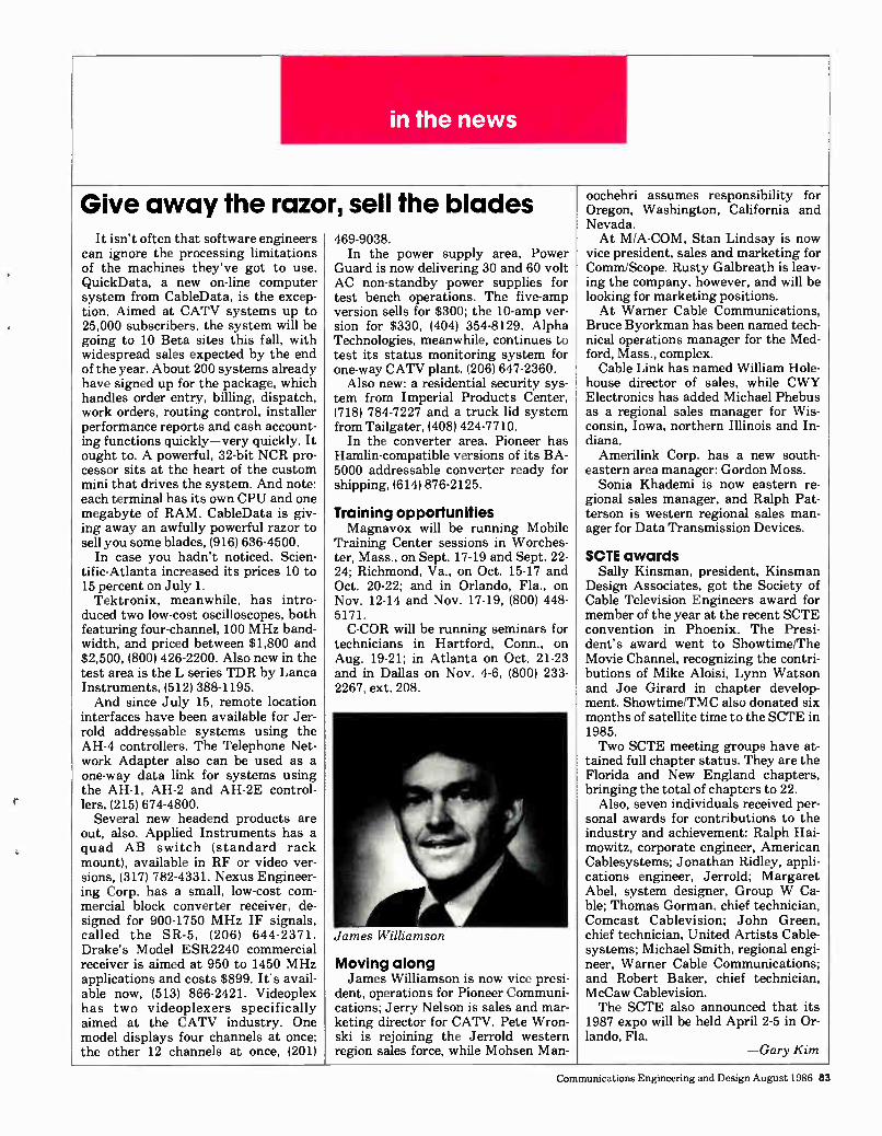
in the news
Give away the razor, sell the blades It isn't often that software engineers
can ignore the processing limitations of the machines they've got to use. QuickData, a new on-line computer system from CableData, is the excep-tion. Aimed at CATV systems up to 25,000 subscribers, the system will be going to 10 Beta sites this fall, with widespread sales expected by the end of the year. About 200 systems already have signed up for the package, which handles order entry, billing, dispatch, work orders, routing control, installer performance reports and cash account-ing functions quickly—very quickly. It ought to. A powerful, 32-bit NCR pro-cessor sits at the heart of the custom mini that drives the system. And note: each terminal has its own CPU and one megabyte of RAM. CableData is giv-ing away an awfully powerful razor to sell you some blades, (916) 636-4500.
In case you hadn't noticed, Scien-tific-Atlanta increased its prices 10 to 15 percent on July 1. Tektronix, meanwhile, has intro-
duced two low-cost oscilloscopes, both featuring four-channel, 100 MHz band-width, and priced between $1,800 and $2,500, (800) 426-2200. Also new in the test area is the L series TDR by Lanca Instruments, (512) 388-1195. And since July 15, remote location
interfaces have been available for Jer-rold addressable systems using the AH-4 controllers. The Telephone Net-work Adapter also can be used as a one-way data link for systems using the AH-1, AH-2 and AH-2E control-lers, (215) 674-4800.
Several new headend products are out, also. Applied Instruments has a quad AB switch (standard rack mount), available in RF or video ver-sions, (317) 782-4331. Nexus Engineer-ing Corp. has a small, low-cost com-mercial block converter receiver, de-signed for 900-1750 MHz IF signals, called the SR-5, (206) 644-2371. Drake's Model ESR2240 commercial receiver is aimed at 950 to 1450 MHz applications and costs $899. It's avail-able now, (513) 866-2421. Videoplex has two videoplexers specifically aimed at the CATV industry. One model displays four channels at once; the other 12 channels at once, (201)
469-9038. In the power supply area, Power
Guard is now delivering 30 and 60 volt AC non-standby power supplies for test bench operations. The five-amp version sells for $300; the 10-amp ver-sion for $330, (404) 354-8129. Alpha Technologies, meanwhile, continues to test its status monitoring system for one-way CATV plant, (206) 647-2360. Also new: a residential security sys-
tem from Imperial Products Center, (718) 784-7227 and a truck lid system from Tailgater, (408) 424-7710.
In the converter area, Pioneer has Hamlin-compatible versions of its BA-5000 addressable converter ready for shipping, (614) 876-2125.
Training opportunities Magnavox will be running Mobile
Training Center sessions in Worches-ter, Mass., on Sept. 17-19 and Sept. 22-24; Richmond, Va., on Oct. 15-17 and Oct. 20-22; and in Orlando, Fla., on Nov. 12-14 and Nov. 17-19, (800) 448-5171. C-COR will be running seminars for
technicians in Hartford, Conn., on Aug. 19-21; in Atlanta on Oct. 21-23 and in Dallas on Nov. 4-6, (800) 233-2267, ext. 208.
James Williamson
Moving along James Williamson is now vice presi-
dent, operations for Pioneer Communi-cations; Jerry Nelson is sales and mar-keting director for CATV. Pete Wron-ski is rejoining the Jerrold western region sales force, while Mohsen Man-
oochehri assumes responsibility for Oregon, Washington, California and Nevada. At M/A-COM, Stan Lindsay is now
vice president, sales and marketing for Comm/Scope. Rusty Galbreath is leav-ing the company, however, and will be looking for marketing positions. At Warner Cable Communications,
Bruce Byorkman has been named tech-nical operations manager for the Med-ford, Mass., complex. Cable Link has named William Hole-
house director of sales, while CWY Electronics has added Michael Phebus as a regional sales manager for Wis-consin, Iowa, northern Illinois and In-diana. Amerilink Corp. has a new south-
eastern area manager: Gordon Moss. Sonia Khademi is now eastern re-
gional sales manager, and Ralph Pat-terson is western regional sales man-ager for Data Transmission Devices.
SCTE awards Sally Kinsman, president, Kinsman
Design Associates, got the Society of Cable Television Engineers award for member of the year at the recent SCTE convention in Phoenix. The Presi-dent's award went to Showtime/The Movie Channel, recognizing the contri-butions of Mike Aloisi, Lynn Watson and Joe Girard in chapter develop-ment. Showtime/TMC also donated six months of satellite time to the SCTE in 1985. Two SCTE meeting groups have at-
tained full chapter status. They are the Florida and New England chapters, bringing the total of chapters to 22.
Also, seven individuals received per-sonal awards for contributions to the industry and achievement: Ralph Hai-mowitz, corporate engineer, American Cablesystems; Jonathan Ridley, appli-cations engineer, Jerrold; Margaret Abel, system designer, Group W Ca-ble; Thomas Gorman, chief technician, Comcast Cablevision; John Green, chief technician, United Artists Cable-systems; Michael Smith, regional engi-neer, Warner Cable Communications; and Robert Baker, chief technician, McCaw Cablevision. The SCTE also announced that its
1987 expo will be held April 2-5 in Or-lando, Fla.
—Gary Kim
Communications Engineering and Design August 1986 83

LAN
Developing products specially for MAP was a risky move, yet full of potential.
Continued from page 65 areas for about five years already, and will in the next fiscal year be making a major commitment to the LAN mar-ket, broadband for sure and possibly other areas as well, according to Dick Shimp, vice president, field services. The Lectro division of Burnup &
Sims will stick to broadband, and re-cently assigned Marty de Alminana to full time LAN sales. The new strategy is about four months old, and, in addi-tion to reorganizing its sales effort, the company is releasing a series of modi-fied power supply products to meet the special needs of the LAN user. A new Mini Brute supply that is wall-mounted, not strand-mounted, is such a product. The unit also has an integral fan—a big selling point to users whose gear is in poorly-ventilated closets. Redundancy also is a special LAN fea-ture. The unit also comes in a rack-mounted version. A rack-mounted standby unit designed for LAN use features a six millisecond switch time. Bob Dickinson, now doing business
as Dovetail Systems, says he's got a product under development in the leak-age area, and is starting to do some network integration as well. Perhaps the most ambitious, and
most risky, proposition tackled to date by any traditional CATV vendor was undertaken by Scientific-Atlanta. You've been reading a lot about the growth of interest in the Manufactur-ing Automation Protocol. S-A's ap-proach to the market has been to push its expertise at the physical layer of broadband networks, whether MAP-compliant or not. But the company went beyond standard broadband products and designed a MAP-com-patible modem. The prototype already has demonstrated its interoperability in the MAP environment, something no other vendor in CATV can match. S-A also developed a MAP-compliant remodulator, both products address-ing the standard's 2.1 version. Because the stream of purchase orders for MAP products has been extremely slow re-cently, both products are in a bit of limbo now.
Gutsy move Developing products specially for
MAP was a gutsy move, and while it
involved more risk and potential than many other strategies, the move points out a fact of life for anybody trying to make money in LANs: al-though everybody's coming to the party, it isn't clear where the party's being held. What is important for any manufac-
turer, though, is to get the specs for the equipment written into the docu-ment when the request for quotes goes out. "Most end users are buying turn-keys, not electronics," says S-A's Pat Miller, marketing manager. "What's important is that they understand the difference between our product and others. So we find we've got to stimu-late the market a little bit."
Miller also makes a good point about the factory automation market as a whole: MAP isn't the whole market. "Many stand-alone controllers will still be used, because not everyone can af-ford full computer-integrated manufac-turing." And like most other players in
broadband LANs, S-A has found that users generally put in LANs to handle data. Gradually they find other uses.
Zenith Electronics also adapted ex-isting CATV expertise for the LAN business, releasing its new Z-LAN 500 system, a 10 Mbps LAN supporting 10,000 nodes and using five six-MHz channels sub-divided into 500 kbps al-locations. Z-LAN uses the CSMA/CD signaling technique, and remote diag-nostics and network management are built right in. A strong point: much lower C/N ratios than comparable products on the market. Even MSOs are looking at the busi-
ness. Viacom Telecommunications al-ready has a dedicated private network unit. At other companies the emphasis seems more localized. Heritage's Jim Randolph, director of engineering, has quite a big data transport operation running, mostly at T-1 rates. Most of the customers in Dallas seem to be us-ing the conduit for bypass of the local telephone company. And while most of the activity is on existing CATV plant, he "gets calls every day from big cor-porations who want LANs." ATC thinks there's a business out there somewhere in data transport, but hasn't yet finalized any specific plans. Not everybody is jumping in with
both feet, though. RMS Electronics knows there's a market out there, but has no particular plans to alter the way it now does business to chase it. Like-wise, Reliable Electric isn't looking aggressively right now because there isn't an immediate fit with the existing manufacturing base. Kennedy Con-struction also has done a few jobs, but isn't quite sure how hard to push, al-though the company certainly wants to diversify. CATV Subscriber Services, for its
part, first began discussing the LAN market about three to four months ago, and thinks its installation, con-struction and design activities in CATV and private cable ought to help. Basically, the company sees itself pro-viding subcontracted installation ser-vices for turnkey operators. And some companies want to stay
away from certain aspects of the busi-ness entirely: NCS Industries, for ex-ample. It got its first LAN job about a year and a half ago, doing system proofing and supplying equipment. It will stay away from construction work, however. Modem repair is okay. "We'll stay away from cable, strand and other stuff that takes up warehouse space," says Dick Grasso, president. "We work the high tech end of the busi-ness." The basic strategy? "We don't stand up to the big IBMs and TRWs. We pick up what they don't want." Not surprisingly, perhaps, supply
giant Anixter, with its heavy base in the telephone world, has made one of the biggest internal reorganizations to tap the LAN market. Essentially, the company has merged its CATV/broad-band product lines with Ethernet, IBM Cabling System and data commu-nications product areas, offering a more unified, multi-media LAN effort. Accompanying the internal moves is a new emphasis on smaller, and more numerous stocking locations. As far as pursuing the LAN market,
Anixter can deliver—from one inte-grated unit—broadband, baseband, or IBM Cabling System options. The company also is making a big effort to supply physical layer products to MAP vendors and users, without much question the biggest such effort in the industry.
—Gary Kim
84 Communications Engineering and Design August 1986

FINALLY, A PRACTICAL SOLUTION TO OUT-OF-SIGHT
MICROWAVE TRANSMISSIONS.
AUntil now, all microwave systems shared this common problem: transmissions that weren't line-
of-sight often drove costs out-of-sight. But with the new low-cost Active Repeater from Hughes Aircraft Company, you can now get around those obstacles
and profit from areas previously too expensive to serve. The easy to install Hughes 2-watt MWB-122 Active
Repeater is directly compatible with all CARS band trans-mitters and receivers including Hughes AMU systems. It is outdoor mounted, totally self-contained, and its low power requirements are easily met by a small DC or solar power source. Whether your microwave path is blocked by man-made or natural obstacles—and whether your transmission is AM or FM— the MWB-122 stands alone as your most practical solution.
This Active Repeater is the latest development in
the most comprehensive line of CARS band microwave equip-ment available.The Hughes AML Microwave Line includes an entire selection of low, medium, and high power transmitters and receivers suitable to every application. In addition, Hughes offers the product quality, experience, and support services that really can remove all obstacles from earning greater profits.
Find out more about the Hughes MWB-122 Active Repeater. Contact: Hughes Microwave Communications Products, Bldg. 245, P.O. Box 2940, Torrance, CA 90509-2940 or call toll free (800) 227-7359, Ext. 6233. In California (213) 517-6233. In Canada: COMLINK Systems Inc.,1420 Bayly Street, Unit 5, Pickering, Ontario L1W 3R4, (416) 831-8282.
HUGHES AlliCPAf t COMPANY
©1986 Hughes Aircraft Company Reader Service Number 47

...there at the start, ...involved today,
. . excited about tomorrow, Oaf El COMMIINICAT1OS
4711 Golf Road ONE CONCOURSE PLAZA SKOK1E,ILLINOIS 80078
(312)677.2600
JOHN e EGAN Presideret August, 1986
An Open Letter to trie CABLE-TV Industry:
Manufacturers have been hard hit by the evolution of the Cable-TV Industry from heavy construction to an operating
and maintenance market.
With this new environment, the industry must address the growing disparity between the success of operators and the current plight of these manufacturf3rs. From their point of view, the maturing of their industry has been painful and the future looks bleak. From the operator's point of
view, the future has never been brighter.
Anixter has served the Cable-TV industry from its beginning, by providing innovative solutions to the industry's product
and supply problems. Anixter Communications sees its role as supply and service specialists working with both manufacturers and operators to eliminate duplication of effort and to reduce manufacturer's and operator's inventory and operating expenses. Anixter also sees its role in helping manufacturers to improve their production planning and provide fast service to operators from strategically located warehouses throughout North America.
While many suppliers are giving up and leaving the Cable-TV industry, Anixter continues working with those who remain, helping them bring their products to the marketplace.
Cable-TV has been a key factor in mak.ing Anixter a substantial New *York Stock Exchange Company. We are extremely strong financially, and we are recommitting ourselves to the continued
growth and prosperity of this indu.stry.
IN TeE NEXT FEW MONTHS YOU WILL SEE US BACK. OUR WORDS
WITH ACTIONS. IN 'THE MEANTIME, IF YOU HAVE ANY IDEAS THAT WILL HELP OUR INDUSTRY, PLEASE CALL US SO 'WE CAN
WORK ON IT TOGETHER.
John M. Egan President
JE:va
©1986 AnIxter Bros., Inc.
MOIR SERVICE IS OUR TECHNOLOGY®
CORPORATE HEADQUARTERS: ANIXTER BROS., INC. 4711 Golf Road, Skokie, IL 60076 (312) 677-2600 — Telex 289464
- Anixter Bros., Inc. 1986

![ESOPS] - World Radio History](https://static.fdokumen.com/doc/165x107/631e25131aedb9cd850f9e54/esops-world-radio-history.jpg)