
DESIGN AND CONSTRUCTION OF A 12 kV D.C. POWER ...
10
Bajopas Volume 2 Number 2 December, 2009 Bayero Journal of Pure and Applied Sciences, 2(2): 175 - 184 Received: July, 2009 Accepted: August, 2009 DESIGN AND CONSTRUCTION OF A 12 kV D.C. POWER SUPPLY Garba Babaji, Department of Physics, Bayero University, PMB 3011, Kano. ABSTRACT An experimental work on a modified version of the so-called Cockroft-Walton type voltage multiplying rectifier was carried out. This involved the study of the factors governing the output voltage of the Cockroft-Walton multiplier, designing a multiplier based on these factors that can yield the targeted output voltage of over 10 kV, and the construction of a 12-kV d.c voltage generator. Essentially, the constructed generator is a modified 32-stage Cockroft-Walton type voltage multiplying rectifier. It is suitable as a power supply for the nitrogen laser. It can also be used in particle acceleration. The results of the study of the factors governing the output of the Cockroft-Walton multiplier, the components type and specification, and the construction and performance of the generator are presented and discussed Keywords: Design, Power, Construction, Cockroft INTRODUCTION A voltage multiplier is an electrical system that converts alternating current (a.c.) electrical power from a lower voltage to a higher direct current (d.c.) voltage by means of capacitors and diodes combined into a network (Naidu, 1996, and Abdel-Salam, 2000). It is a known fact that when voltages are stepped up by means of transformers, the output current decreases. This is also true of voltage multipliers. Although the measured open-circuit output voltage of a voltage multiplier may be several times greater than the input voltage, once a load is connected the value of the output voltage decreases (Horowitz and Hill 1982). Voltage multipliers may be classified as voltage doublers, triplers, quadruplers, ect. The classification depends on the ratio of the output voltage to the input voltage. For example, a voltage multiplier whose open-circuit output voltage is two times the peak of the a.c. input voltage, V p is called a voltage doubler. Voltage multipliers ‘amplify’ the input voltage through the use of series-aiding voltage sources. This can be compared to the connection of dry cells (batteries) in series. A voltage doubler is illustrated in Fig.1. During the negative half-cycle of the a.c. input voltage, e in the diode, d 1 conducts and allows the capacitor c 1 to charge to the peak voltage, V p with the polarity shown. Near the peak of positive half- cycle of the input, the diode d 2 conducts and hence the capacitor c 2 is charged. However, at this instant, the charge retained in c 1 causes it to act like a voltage source nearly equal to the peak of the a.c. input. As a result, c 2 charges to a voltage nearly equal to twice V p with the polarity as shown in Fig.1. This process continues in successive cycles so that after a few cycles c 2 is charged to 2V p . Figure 1: Voltage Doubler Circuit. 175
-
Upload
khangminh22 -
Category
Documents
-
view
1 -
download
0
Transcript of DESIGN AND CONSTRUCTION OF A 12 kV D.C. POWER ...

Bajopas Volume 2 Number 2 December, 2009
Bayero Journal of Pure and Applied Sciences, 2(2): 175 - 184 Received: July, 2009 Accepted: August, 2009
DESIGN AND CONSTRUCTION OF A 12 kV D.C. POWER SUPPLY
Garba Babaji, Department of Physics, Bayero University, PMB 3011, Kano.
ABSTRACT An experimental work on a modified version of the so-called Cockroft-Walton type voltage multiplying rectifier was carried out. This involved the study of the factors governing the output voltage of the Cockroft-Walton multiplier, designing a multiplier based on these factors that can yield the targeted output voltage of over 10 kV, and the construction of a 12-kV d.c voltage generator. Essentially, the constructed generator is a modified 32-stage Cockroft-Walton type voltage multiplying rectifier. It is suitable as a power supply for the nitrogen laser. It can also be used in particle acceleration. The results of the study of the factors governing the output of the Cockroft-Walton multiplier, the components type and specification, and the construction and performance of the generator are presented and discussed
Keywords: Design, Power, Construction, Cockroft INTRODUCTION A voltage multiplier is an electrical system that converts alternating current (a.c.) electrical power from a lower voltage to a higher direct current (d.c.) voltage by means of capacitors and diodes combined into a network (Naidu, 1996, and Abdel-Salam, 2000). It is a known fact that when voltages are stepped up by means of transformers, the output current decreases. This is also true of voltage multipliers. Although the measured open-circuit output voltage of a voltage multiplier may be several times greater than the input voltage, once a load is connected the value of the output voltage decreases (Horowitz and Hill 1982).
Voltage multipliers may be classified as voltage doublers, triplers, quadruplers, ect. The classification depends on the ratio of the output voltage to the input voltage. For example, a voltage multiplier whose open-circuit output voltage is two
times the peak of the a.c. input voltage, Vp is called a voltage doubler. Voltage multipliers ‘amplify’ the input voltage through the use of series-aiding voltage sources. This can be compared to the connection of dry cells (batteries) in series.
A voltage doubler is illustrated in Fig.1. During the negative half-cycle of the a.c. input voltage, ein the diode, d1 conducts and allows the capacitor c1 to charge to the peak voltage, Vp with the polarity shown. Near the peak of positive half-cycle of the input, the diode d2 conducts and hence the capacitor c2 is charged. However, at this instant, the charge retained in c1 causes it to act like a voltage source nearly equal to the peak of the a.c. input. As a result, c2 charges to a voltage nearly equal to twice Vp with the polarity as shown in Fig.1. This process continues in successive cycles so that after a few cycles c2 is charged to 2Vp.
Figure 1: Voltage Doubler Circuit.
175

Bajopas Volume 2 Number 2 December, 2009
The circuit for a voltage multiplier which apparently can be extended indefinitely is drawn in Fig.2. It has been pointed out ( Robert, 1975) that even though this voltage multiplier circuit was first described in 1921 by Greinnacher, it is often identified with Cockroft and Walton particularly in English Language publications because of their pioneer application of it for positive ion acceleration. A comparison of Figs. 1 and 2 reveals that the so called Cockroft-Walton voltage multiplier is made up of a number of voltage doublers in series. When the a.c. input is switched on, capacitors c2, c4, c6, c8, etc gradually charge up until each has a potential difference of 2Vp across it. Capacitors c3, c5, c7, c9 etc on the other hand, act as a.c. coupling capacitors transmitting the a.c. wave to diodes d2, d4, d6, d8, etc. At the steady state, the open-circuit potential difference, V0(n) across a multiplier
consisting of n stages (a voltage doubler consist of two stages ) is given by (Jones, M. H. 1985) as V0(n) = nVp . (1)
The operation of the Cockroft-Walton voltage multiplier circuit has been explained by Gilgenback, (1988) by considering the response to the sinusoidal input voltage, ein = Vp tωsin . The polarity of the diode
d1 allows capacitor c1 to be charged such that the voltage at point B (Fig.2) is equal to Vp + Vp tωsin . This
voltage charges the capacitor c2 through the diode d2. so that the voltage at point G is 2Vp . This process repeats through the stages so that the voltage is equal to 2Vp +Vp tωsin at point C and 4Vp at point F.
Figure 2: Circuit Diagram of the Cockroft-Walton Voltage Rectifier and Multiplier.
A finite load current, IL drawn from the multiplier causes the output voltage to drop by certain amount, Vrip during the a.c. input cycle. The resulting unevenness in the d.c output is called ripple and appears as an a.c. wave form superimposed on the steady d.c.. The ripple also has the
effect of reducing the average output voltage. A load current, IL drawn from the Cockroft-Walton voltage multiplier results in a ripple voltage given by Kuffel, et al (2000) as
Cf
nnnIV
L
rip
⎥⎦
⎤⎢⎣
⎡−+
=623
2 23
, (2)
176

Bajopas Volume 2 Number 2 December, 2009
where f is the frequency of the ripple voltage. Thus, the average output voltage, V0 from such multiplier arrangement is given by:
Cf
nnnIrVV
L
p
⎥⎦
⎤⎢⎣
⎡−+
−=623
2 23
0 . (3)
However, for large n, n3>>n2, therefore
CfnInVV L
p 32 3
0 −≈ . (4)
But even at zero load current, there is a difference between the ideal output voltage given by Eq. [1] and the voltage that is actually realized. For small n, this voltage drop is mainly due to the source impedance and the rectifier losses. If n is large, the output voltage is further reduced by the effects of leakage current in the capacitors and the current flowing thorough the various stray capacitance particularly when the reservoir capacitors are of small capacitance ( Haibo, et al 1994 and Mariun, et al 2006 ). Molecular nitrogen lasers have proved to be among the most versatile. Their strong fast pulsed output in the near ultraviolet is ideally suited for pumping organics dye lasers (Wang, 1976), for fluorescent studies (Hilborn, 1976), Raman spectroscopy (Kunabenchi, et al 1982), and laser isotope separation (Snabely, 1974). The condition for laser action in molecular nitrogen is easily satisfied and permits a wide variety of design to be used. The most commonly used design employs transverse pumping with a pulse electric discharge. Commercial nitrogen lasers are available with costs ranging from a few thousand dollars to over $20,000 and peak power ratings ranging from 1kW to several mega-watts for the most expensive units. Fortunately, it is possible to construct a reliable high-power nitrogen laser for less than one-tenth the cost of the comparable commercial unit (Tan and Low, 1984 and Hilbom, 1976). Essentially, the nitrogen laser consists of a channel that contains nitrogen gas, a switching system
and high voltage supply. It has been found (Tan and Low, 1984) that the nitrogen laser operates best when its storage capacitors are charged to a voltage that lies between 10 and 25kV. Such high voltages are in general, obtained from a Marx generator, a voltage multiplier, a power transformer, or a combination of voltage multiplier with power transformer. In this work, a power supply unit suitable for pumping a nitrogen laser is designed and constructed entirely by means of locally available and affordable components. The constructed power supply is a modified version of the so called Cockroft-Walton type voltage multiplier. The present work is the first practical step in our efforts to construct a low cost nitrogen laser using locally available components. Rectifier and Capacitor Ratings The selection of diodes and capacitors for voltage multipliers need considerable care. This will be illustrated by considering the half-wave (HW) rectifier shown in Fig.3. The voltage across the reservoir capacitor in a steady state is equal to Vp . When end A of the transformer secondary is negative the diode is not conducting (because it is reversed-biased), but the reservoir capacitor at the diode cathode is charged to the positive peak value of the input a.c voltage. Since the diode is experiencing the negative value of Vp from the transformer, the potential difference across it is 2Vp and it must be able to withstand this reverse voltage without avalanche breakdown.
Fig.3 Half Wave Voltage Rectifier Circuit.
Although theoretically, a PIV (Peak Inverse Voltage) rating of 2Vp is adequate, in practice it is necessary to
chose a diode of PIV greater than this in order to allow for transient voltage pulses at the transformer secondary
177
Bajopas Volume 2 Number 2 December, 2009
as a result of mains borne interference and which may be sufficient to break down the rectifier junctions. The variac used in this work can provide an a.c. voltage in the range 0-280 V, therefore, the diodes in the voltage multiplier whose input voltage is obtained from the variac must be
of PlV greater than 792 V ( N.B. Vp = in2 V ). The
diodes used i.e IN4007 have PIV greater than 792V, thus there will be no problem of junction break-down. A careful look at Fig.2 reveals (as explained above) that the theoretical potential difference at zero load current across each of capacitors c2, c6, c8, c10 etc is 2Vp, and across each of capacitors c1, c3, c7, c9 c11, is Vp. However, due to leakage current which becomes more important as the number of stages in the multiplier is increased, the actual potential difference may be lower than 2Vp and Vp for the even-and odd-numbered capacitors respectively. However, to be on the safer side, the potential difference across each of these capacitors should not exceed their voltage rating, i.e. magnitude of the applied input voltage must be restricted so that the potential difference is lower than the voltage rating. Thus, for the multiplier in which all the capacitors are the aluminum electrolytic of voltage rating 400V, the input voltage should not exceed 138V. Tests, Analysis and Design A common setback encountered in experimental work in a developing country such as Nigeria is the difficulty in getting the desired components. One is forced to use components that are available which may not be the desired ones. Therefore, in order to get the best from what we had at our disposal, a series of preliminary experiments in which the factors governing the output voltage were conducted. The results of these experiments were then used in designing a circuit that can produce (using the components available) sufficient voltage to pump a nitrogen laser. The equipment and components available for constructing the multiplier circuit in this work are as follows:
1. One variac which is of the Fisher Scientific type 3PN1020. It has a capacity of 0.98 kVA and can provide 0-280 V a.c.
2. About two hundred piece of IN4007 diodes of peak inverse voltage (PIV) of 1 kV.
3. Seventy pieces of disc ceramic capacitors of 4 kV d.c. rating, and capacitance of 372 pF.
4. One hundred pieces of polypropylene capacitors of 1 kV d.c rating, and capacitance of 0.01
Fμ .
5. One hundred pieces of polypropylene capacitors of 1kV d.c. rating, and capacitance of 0.022
Fμ .
6. One hundred pieces of polypropylene capacitors of 1 kV d.c. rating and capacitance of 0.047
Fμ .
7. Twenty five pieces of polypropylene capacitors of 1 kV d.c. rating and capacitance of 0.2
Fμ .
8. Forty nine pieces of aluminium polarized capacitors of 400 V d.c ratings and capacitance of 4.7 Fμ .
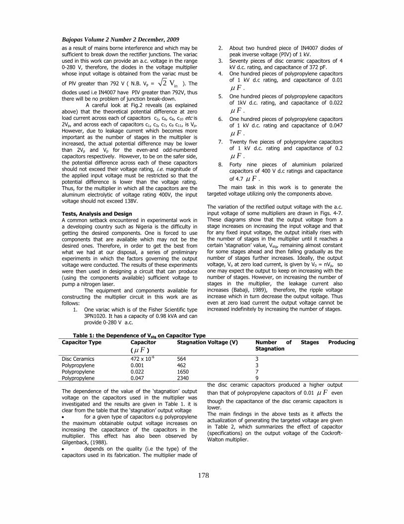
The main task in this work is to generate the targeted voltage utilizing only the components above. The variation of the rectified output voltage with the a.c. input voltage of some multipliers are drawn in Figs. 4-7. These diagrams show that the output voltage from a stage increases on increasing the input voltage and that for any fixed input voltage, the output initially rises with the number of stages in the multiplier until it reaches a certain ‘stagnation’ value, Vstg, remaining almost constant for some stages ahead and then falling gradually as the number of stages further increases. Ideally, the output voltage, Vo at zero load current, is given by V0 = nVp, so one may expect the output to keep on increasing with the number of stages. However, on increasing the number of stages in the multiplier, the leakage current also increases (Babaji, 1989), therefore, the ripple voltage increase which in turn decrease the output voltage. Thus even at zero load current the output voltage cannot be increased indefinitely by increasing the number of stages.
Table 1: the Dependence of Vstg on Capacitor Type
Capacitor Type Capacitor ( Fμ )
Stagnation Voltage (V) Number of Stages Producing Stagnation
Disc Ceramics 472 x 10-6 564 3 Polypropylene 0.001 462 3 Polypropylene 0.022 1650 7 Polypropylene 0.047 2340 9 The dependence of the value of the ‘stagnation’ output voltage on the capacitors used in the multiplier was investigated and the results are given in Table 1. it is clear from the table that the ‘stagnation’ output voltage • for a given type of capacitors e.g polypropylene the maximum obtainable output voltage increases on increasing the capacitance of the capacitors in the multiplier. This effect has also been observed by Gilgenback, (1988). • depends on the quality (i.e the type) of the capacitors used in its fabrication. The multiplier made of
the disc ceramic capacitors produced a higher output than that of polypropylene capacitors of 0.01 Fμ even
though the capacitance of the disc ceramic capacitors is lower. The main findings in the above tests as it affects the actualization of generating the targeted voltage are given in Table 2, which summarizes the effect of capacitor (specifications) on the output voltage of the Cockroft-Walton multiplier.
178

Bajopas Volume 2 Number 2 December, 2009
179
Bajopas Volume 2 Number 2 December, 2009
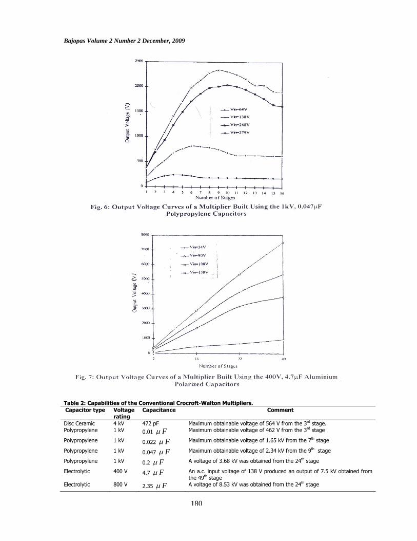
Table 2: Capabilities of the Conventional Crocroft-Walton Multipliers. Capacitor type Voltage
rating Capacitance Comment
Disc Ceramic 4 kV 472 pF Maximum obtainable voltage of 564 V from the 3rd stage. Polypropylene 1 kV 0.01 Fμ Maximum obtainable voltage of 462 V from the 3rd stage
Polypropylene 1 kV 0.022 Fμ Maximum obtainable voltage of 1.65 kV from the 7th stage
Polypropylene 1 kV 0.047 Fμ Maximum obtainable voltage of 2.34 kV from the 9th stage
Polypropylene 1 kV 0.2 Fμ A voltage of 3.68 kV was obtained from the 24th stage
Electrolytic 400 V 4.7 Fμ An a.c. input voltage of 138 V produced an output of 7.5 kV obtained from the 49th stage
Electrolytic 800 V 2.35 Fμ A voltage of 8.53 kV was obtained from the 24th stage
180

Bajopas Volume 2 Number 2 December, 2009
It should be remembered that in the original
Cockroft-Walton multiplier all the capacitors used are the same with respect to their type, voltage rating, and capacitance. As can be seen from Table 2, it will not be possible to generate the targeted voltage by using either the disc ceramics capacitors or any of the polypropylene capacitors of capacitance 0.01 Fμ , 0.022 Fμ or
0.047 Fμ because the values of their ‘stagnation’
output voltage, Vstg of 564 V, 462 V, 1.62 kV and 2.3 kV respectively are far below the required voltage. In the case of the polypropylene capacitor of capacitance 0.2 Fμ , a voltage of 3.68 kV was obtained from the
12th stage of a capacitor of a multiplier constructed using it. Even though ‘stagnation’ has not been reached and thus a higher voltage could have been obtained by increasing the number of stages, however, all but one of the available 0.2 Fμ polypropylene capacitors were
used in the 12-stage multiplier. In addition, these capacitors are fairly large and the multiplier made of them will be too big. An input voltage of 138 V produced an output of 7.5 kV in a 49-stage multiplier constructed using the polarized aluminium capacitors of capacitance 4.7 Fμ , and d.c. voltage rating of 400 V. A higher
voltage could have been obtained by increasing the input, however, in doing so the voltage rating of the capacitor will be exceeded and consequently damaged. In a bid to get a higher voltage, a 24-stage multiplier was set up using aluminium polarized capacitors of capacitance 2.35
Fμ and voltage rating of 800 V. These capacitors were
obtained by joining two aluminium polarized capacitors each of capacitance 4.7 Fμ and voltage rating of 400
V in series. An output voltage of 8.53 kV was produced by an input voltage of 280 V. It was not possible to increase the number of stages so that a higher output voltage is realized because all the available aluminium polarized capacitors were utilized. Thus, by using the available components and employing the original Cockroft-Walton circuit, it will not be possible to generate the targeted voltage. The conventional Cockroft-Walton circuit has to be modified in order to generate the targeted voltage. A way to do this was realized on a comparison of the roles of the odd numbered (i.e c1, c3, c5, etc) and the numbered (c2, c4, c6, etc) capacitors in the multiplication process. The output voltage from multipliers referred to as ‘D’ and ‘E’ (and whose composition is explain below) for some input voltages are shown in Table3.
Table 3. Comparison of the Output Voltages of Multipliers ‘D’ and ‘E’ Input Voltage (V) Output Voltage (V) ‘D’ ‘E’ 25 78 197 80 470 1300 200 910 3600 270 1200 4800
Each of these multipliers is composed of 16 stages. In ‘E’ the odd-numbered capacitors (i.e those that are designated by odd number subscript in Fig.2) were the polypropylene of d.c. voltage rating of 1000V and capacitance of 0.2 Fμ , while the even capacitors were
the aluminium polarized of d.c. voltage of 800V and
capacitance of 2.35 Fμ . In ‘D’ the positions of these
capacitors were interchanged. The multiplier ‘E’ performed better than ‘D’ thus, showing that the even number capacitors are more important in the multiplication process and so their quality has more profound effect on the output voltage.
The Constructed Power Source The circuit of the constructed generator is shown, in Fig.8. It is a 32-stage modified Cockroft-Walton type voltage multiplier. The a.c. input voltage was provided by the variac.
The value of the output voltage is measured by a 0-100 Aμ d.c. micro-ammeter adapted for high voltage
measurement. The entire cascade unit of the generator was connected through a key, to a water pipe in order to facilitate the discharging of the capacitors. The components used in the construction of the generator are of the following specifications:
181

Bajopas Volume 2 Number 2 December, 2009
1. The variac is the Fisher Scientific Auto-transformer type 3 PN 1020. It can provide 0-280 V a.c. and has a
capacity of 0.98 kVA. 2. All the diodes are IN 4007 . 3. Capacitors c25, c27, c29 and c31 are polypropylene of 0.2 Fμ capacitance and d.c. voltage rating of 1000 V.
4. All the other capacitors are the aluminium polarized type 2.35 Fμ capacitance and d.c. voltage rating of
800 V. 5. The micro-ammeter is the Philip Harris of range 0-100 Aμ d.c .
6. The 159.8 ΩM resistor consist of thirty four pieces of 4.7 ΩM resistors in series. The 159.8 ΩM resistor was mounted on two plastic circuit boards, while the cascade unit was fabricated on four such boards. The resistor and cascade modules were then neatly packed into a wooden box. The micro-ammeter was also placed in the box with its face facing the outside in order to facilitate reading the value of the output voltage.
182

Bajopas Volume 2 Number 2 December, 2009
The generator is operated as follows:
1. Connect the variac to the mains supply. 2. Connect the variac’s output to the input terminals of the multiplier circuit. 3. Set the variac’s output to zero by means of the output control knob. 4. Switch on the variac and steadily increase its output by means of the control knob. 5. Read the value of the output voltage from the kilo-voltmeter (i.e micro-ammeter adapted for high votage
measurement). It should be noted that: i) On putting off the variac, it takes some time for
the capacitors to be discharged and the output voltage to fall to zero. Thus if one wishes to instantly reduce the value of the output voltage, then the variac must be switched off, its output control knob set to zero, and the capacitors discharged. The kilovotlmeter will indicate when the capacitors are fully discharged. It is also essential to discharge the capacitors each time after using the generator.
ii) If no output voltage is obtained on increasing the variac’s output, then most probably the 4A protective fuse of the variac must have blown off
and so should be checked, and if necessary replaced.
As expected, the magnitude of the output voltage depends on the value of the input voltage from the variac. The output voltage corresponding to various input voltage are given in Table 4. The measurement of the output voltage was carried out using three different meters, namely the Altai YN-360TR, the Eagle MM100N, and the Miselco Mini 20. The 1000 V d.c. range of each of these meters was extended to 15.0kV for the purpose of the output voltage measurement. The value of an output voltage given in Table 4 is the average of the values from the three meters.
Table 4: Output Voltage of the Constructed Generator Vin (V) a.c. 28 56 84 112 140 168 196 224 252 280 V0 (kV) d.c. 1.032 2.628 3.504 4.620 5.940 7.050 8.244 9.522 10.97 12.12 DISCUSSION Since its invention, the Cockroft-Walton voltage multiplier has been receiving the attention of researchers, therefore, great advances have been made both in terms of it’s form and application. Initially, the Cockroft-Walton voltage multiplier was used for particle acceleration, however, recently Kim et al, (2008) presented a full wave voltage multiplier for RFID transponders, and Kazuhiro et al, (2006) described a battery charger using the Cockroft-Walton voltage multiplier. In terms of its form, the original Cockroft-Walton voltage multiplier was composed of discrete identical diodes and identical capacitors. In 1976, Dickson reported a modified Cockroft-Walton multiplier that is constructed with NMOS integrated circuits. Sam and Ali (2007) introduced a novel breakdown voltage that generate high output voltage swings using transistors. Also, Davor et al (2009) presented a modified Cockroft-Walton voltage multiplier that used switched capacitors technique.
The voltage multiplier unit of the constructed generator is made of thirty-two diodes and capacitors respectively. Of these capacitors, twenty –eight are of the polarized aluminium type, while the remaining four are of the polypropylene type. Normally, all the capacitors should have been of the same type and preferably of equal capacitance. However, the available polarized aluminium capacitors were not sufficient to fabricate a multiplier that could deliver the targeted output voltage of 12 kV. Thus, an additional polypropylene capacitors have to be used in order to increase the number of stages to be able to produce the desired output. These polypropylene capacitors are positioned at c25, c27, c29
and c31 because placing them else where was found to lower the magnitude of the output voltage. Thus the voltage multiplier constructed is indeed a modified Cockroft-Walton voltage multiplier. It has been observed that when the generator is switched off, it takes some time for the capacitors to be fully discharged and consequently the output voltage to fall to zero. The rather long period of discharge is because the aluminium capacitors, being electrolytic and therefore, retain the charge stored in them for a long period of time. To discharge the capacitors instantly, the key, S (Fig.8) is closed. On doing so, the charge stored in the capacitors is passed to the connected water pipe (at earth potential), which enables the output fall instantly to zero. CONCLUSION The constructed generator is a 32-stage voltage multiplier. The input is provided by a 0-280 V variac. The maximum output voltage is 12.120kV. The output voltage of the generator has a slow rise and fall times. On applying an input, the output voltage steadily increases and in general takes about one minute to reach its final value. Also, it takes several hours for the output voltage to fall to zero after the input is switched off, consequently the capacitors have to be discharged each time after using the generator. A power supply capable of producing 10-25kV d.c is required to pump a nitrogen laser. Therefore, the constructed generator may be used for this purpose. It can also be used in particle acceleration and gaseous discharge experiments.
REFERENCES Abdel-Salam, M. (2000). High Voltage Generation, in High
Voltage Engineering: Theory and Practice Edited
by M. E. Khalifa, Marcel Dekker Inc. New York, pp 519- 566.
Babaji, G. (1989). A Power Supply Applicable the Nitrogen Laser, Dissertation, Bayero University, Kano p.96.
183

Bajopas Volume 2 Number 2 December, 2009
Davor, V.; Tomislay, S. and Tomisly, M. (2009). Modification of the Cockroft-Walton Charge Pump by Using Switched Capacitors Techniques for Improved Performance Under Capacitve Loads, WSEAS Transactions on Circuits and Systems, vol. 8 no. 1, p.167.
Fitzsimmons, W. A.; Anderson, L. W.; Riedhauser, C. E. and Vrtilek, J. M. (1976). Experimental and Theoretical Investigation of the Nitrogen Laser, IEEE Journal of Quantum Electronics, vol. QE12, p.624.
Gilgenback, R.M. (1988). Low Voltage Models of Particle Accelerator Circuits, American Journal of Physics Vol. 56, No.9, p.822.
Haibo, Z.; Akio, T. and Katsumi, U. (1994). A Numerical Analysis Approach to Cockroft-Walton in Electron Microscope, Journal of Electron Microscopy, 43(1), p. 25.
Hilbom, R.C. (1976). An Inexpensive Reliable Higher-Power Molecular Nitrogen Laser, American Journal of Physics, Vol. 44, No. 12, p.1172.
Horowitz, P. and Hill, W. (1982). The Art of Electronics, Cambridge University Press Cambridge, p.39.
Jones, M.H. (1985). A Practical Introduction to Electronic Circuits. Cambridge University Press, Cambridge, page 109.
Kazuhiro, T., Satoru, T., Tatsuo, N., Takashi, E., Tateiki, O. and Michio, S. (2006). Design and Operation Verification of Integrated Battery Assembly Charger Using Cockroft- Walton Circuit, Journal of Asian Electric Vehicles, Vol. 2, No. 2, p.953.
Kim, S., Cho, J. H. and Hong, S. (2008). A Full Wave Voltage Multiplier for RFID Transponders, IEICE Transactions on Communications, E91-B(1), p. 388,
Kuffel, E., Zaengl, W. S. and Kuffel, J. (2000). High Voltage Engineering, Butterworth-Heinemann, Oxford. Chapt. two
Kunabenchi, R.S.; Gorbal, M. R. and Savadatti, M. I. (1982). Simple Nitrogen Laser, American Journal of Physics, Vol. 50, No.6, p.568.
Mariun, N., Ismail, D., Anayet, K.; Khan, N. and Amran, M. (2006). Simulation, Design and Construction of a High Voltage DC Power Supply at 15 kV Output Using Voltage Multiplier Circuits, American Journal of Applied Sciences, 3(12), p.2178.
Naidu, M. S. and Kamaraju, V. (1996). High Voltage Engineering, McGraw Hill Publishing Company, London, chapter six.
Riccardo, P. (1976). Design of a Reliable, High-power, Nitrogen Laser, Optical and Quantum Electronics, vol. 8, no. 6, p. 565.
Robert, P.F. (1975). Cockroft-Walton Voltage Multiplier, In Methods of Experiments Physics Vol.2 (Electronic Methods), Part ‘A’ Edited by E. Blear and R.O. Haxby, Academic Press New York, p.189.
Sam, M. and Ali, H. (2007). A Breakdown Voltage Multiplier for High Voltage Swing Drivers, IEEE Journal of Solid-State Circuits, Vol.42, No. 2, p.302.
Snabely, B.B. (1974). Laser Isotope Separation. Proc. VIII International Quantum Electronic Conference. P. 758.
Tan, C.H. and Low, K.S (1984). The Nitrogen Laser, Proc. 1st Tropical College on Applied Physics p.134.
Wang, C.P. (1976). Simple Fast-Discharge Device for High-Power Pulsed Lasers, Rev. Sci. Instrum. Vol 1. No.1 p.92.
184