. BID DOCUMENT FOR “Construction of 33 KV bay ... - Apdcl.org
91
. BID DOCUMENT FOR “Construction of 33 KV bay with terminal equipments at 33/11 KV Nellie Substation, Construction of 33/.433 KV 2 MVA Sub Stations at JRN Pharma & Laboratories LLP at Borgaon,Killing Valley,Morigaon Campus,Construction of 33 KV Line with MVCC from 33/11 KV Nellie Substation to 33/0.433 KV 2 MVA Substation under Jagiroad Electrical Sub Division of Morigaon Electrical Circle, APDCL” ON “PARTIAL TURNKEY” MODE SCHEME: Deposit Scheme. NIT NO: 2021-22/1/APDCL (CAR)/JRN Pharma/Morigaon Dtd. 16.09.2021
-
Upload
khangminh22 -
Category
Documents
-
view
0 -
download
0
Transcript of . BID DOCUMENT FOR “Construction of 33 KV bay ... - Apdcl.org

.
BID DOCUMENT
FOR
“Construction of 33 KV bay with terminal equipments at 33/11 KV Nellie Substation, Construction of
33/.433 KV 2 MVA Sub Stations at JRN Pharma & Laboratories LLP at Borgaon,Killing Valley,Morigaon
Campus,Construction of 33 KV Line with MVCC from 33/11 KV Nellie Substation to 33/0.433 KV 2 MVA
Substation under Jagiroad Electrical Sub Division of Morigaon Electrical Circle, APDCL”
ON
“PARTIAL TURNKEY” MODE
SCHEME: Deposit Scheme.
NIT NO: 2021-22/1/APDCL (CAR)/JRN Pharma/Morigaon Dtd. 16.09.2021

NIT NO: 2021-22/1/APDCL (CAR)/JRN Pharma/Morigaon Dtd. 16-09-2021 Page 2 of 91
INDEX
Page No:
Section – I Notice Inviting Tender 3-6
Section – II Tender Inviting Proposal 7-22
Section – III Bill of Quantity (BOQ) 23-27
Section – IV General Requirements 28-31
Section – V Forms of Bid 32-43
Section – VI Technical Specifications 44-91

NIT NO: 2021-22/1/APDCL (CAR)/JRN Pharma/Morigaon Dtd. 16-09-2021 Page 3 of 91
SECTION-I
(Notice Inviting Tender)

NIT NO: 2021-22/1/APDCL (CAR)/JRN Pharma/Morigaon Dtd. 16-09-2021 Page 4 of 91
O/o the Chief General Manager (D), Central Assam Region.
2nd Floor, Bijulee Bhawan, Paltanbazar, Guwahati – 1 E-mail: [email protected]
NIT NO: 2021-22/1/APDCL (CAR)/JRN Pharma/Morigaon Dtd. 16-09-2021
The Chief General Manager (D), CAR, Assam Power Distribution Co. Ltd. Bijulee Bhawan, Paltanbazar,
Guwahati-1, invites E- tenders from valid Empanelled Engineering Firms/Contractors in CMS portal of APDCL
having valid Electrical Contractor’s License up to 33 KV level for the following works:
“Construction of 33 KV bay with terminal equipments at 33/11 KV Nellie Substation, Construction
of 33/.433 KV 2 MVA Sub Stations at JRN Pharma & Laboratories LLP at Borgaon,Killing Valley,Morigaon
Campus, Construction of 33 KV Line with MVCC from 33/11 KV Nellie Substation to 33/0.433 KV 2 MVA
Substation under Jagiroad Electrical Sub Division of Morigaon Electrical Circle, APDCL under Deposit
Scheme on Partial Turnkey mode”
Details may be seen in websites www.assamtenders.gov.in or www.apdcl.org. w.e.f. 10 A.M on 18.09.2021
Description Date Time
Tender Document Publishing date 18.09.2021 10:00 Hrs
Pre-Bid Queries (through e-mail) 21.09.2021 From 10:00 Hrs. to 16:00 Hrs.
Bid-Submission Start date & time 23.09.2021 From 17:00 Hrs.
Bid-Submission End date & time 28.09.2021 Up to 16:00 Hrs.
Technical Bid Opening date & time 30.09.2021 At 14:00 Hrs.
-Sd-
Chief General Manager (D),
APDCL, CAR, Bijulee Bhawan, Ghy-1
Memo No: CGM (D)/APDCL (CAR)/JRN Pharma/Morigaon/2021-22/ 4(a) Dtd: 16.09.2021
Copy to: -
1. PS to MD, APDCL for kind appraisal of MD.
2. The CGM(M, CR & S), APDCL, Bijulee Bhawan, Paltan Bazar, Guwahati-1 for publication of the above
tender in one issue of “The Assam Tribune” and one Assamese daily news paper.
3. The OSD to the Chairman, APDCL/AEGCL/APGCL, Bijulee Bhawan, Paltan bazaar, Guwahati for
publication in the official website.
4. The GM (Revenue), Nagaon Zone, APDCL for information.
5. The CEO, Morigaon Electrical Circle, APDCL for information.
-Sd-
Chief General Manager (D),
APDCL, CAR, Bijulee Bhawan, Ghy-1

NIT NO: 2021-22/1/APDCL (CAR)/JRN Pharma/Morigaon Dtd. 16-09-2021 Page 5 of 91
O/o the Chief General Manager (D), Central Assam Region.
2nd Floor, Bijulee Bhawan, Paltanbazar, Guwahati – 1 E-mail: [email protected]
NOTICE INVITING TENDER
NIT NO: 2021-22/1/APDCL (CAR)/JRN Pharma/Morigaon Dtd. 16-09-2021
The Chief General Manager (D&S), CAR, Assam Power Distribution Co. Ltd., Bijulee Bhawan, Paltanbazar,
Guwahati-1, invites E- tenders from Enlisted Electrical Contractors in CMS portal of APDCL having valid
Electrical Contractor’s License up to 33 KV level issued by the competent authority on partial Turnkey mode of
contract.
Work description
Minimum Average
Annual
Turnover(MAAT)
(in lakh) for
[FY 2018-19, FY
2019-20 & FY 2020-
21(Audited or Prov.)]
EMD
amount
(in
lakh)
Period of
completion
in days
Tender
processing
fees in Rs.
“Construction of 33 KV bay with terminal
equipments at 33/11 KV Nellie Substation,
Construction of 33/.433 KV 2 MVA Sub
Stations at JRN Pharma & Laboratories
LLP at Borgaon, Killing Valley,Morigaon
Campus, Construction of 33 KV Line with
MVCC from 33/11 KV Nellie Substation to
33/0.433 KV 2 MVA Substation under
Jagiroad Electrical Sub Division of
Morigaon Electrical Circle, APDCL under
Deposit Scheme on Partial Turnkey mode”
500 10.0 180 10,000
1. Source of fund: “Deposit Scheme”
2. TENDER PROCESSING FEES: The Bid documents can be downloaded from the websites:
www.assamtenders.gov.in or www.apdcl.org for tender submission purpose. The bidder shall mandatorily
make payment of tender processing fees and Earnest money deposit ((EMD) through internet banking or
through NEFT/RTGS. Procedures for submission of Tender processing fees and EMD may be seen in the
‘Announcements’ tab of E-tendering portal www.assamtenders.gov.in. Any other mode of payment for
submission of tender processing fees and EMD shall not be accepted.
3. Earnest money: As shown in the table above.
4. Eligibility Criteria:
a) The intending Bidder (including JV partner) must be registered in the Contract Management System
(CMS) portal of APDCL before submission of bid.
b) Average annual turnover of the bidder for last three consecutive financial years i.e. FY 18-19, 19-20 & 20-
21(Prov. or audited) for the package, supported by audited balance sheet, shall be as per the requirements
shown in the table and duly certified by Registered Chartered Accountant with Registration No.
c) Past and present performance of the bidder in any Electrical utility within India will be taken into account to
decide the eligibility as per clause mentioned in the detail bid document.
d) Financial resources: The bidder shall have to specify proposed source of financing, such as liquid assets,
unencumbered real assets, letter of credit and other financial means, net current commitments etc. available to
meet the total construction cash flow demand of the subject contract (evaluation & qualification criteria).
e) Other Eligibility Criteria may be seen at detail bid document.

NIT NO: 2021-22/1/APDCL (CAR)/JRN Pharma/Morigaon Dtd. 16-09-2021 Page 6 of 91
5. Bid validity: 180 days from the last date of submission of Bid.
6. Pre-bid Queries: From 10:00 Hrs. of 21.09.2021 to 16:00 Hrs. of 21.09.2021
(Pre-bid Queries shall only be submitted via e-mail at [email protected])
7. Settlement of Queries: From 10:00 Hrs. of 22.09.2021 to 16:00 Hrs. of 23.09.2021
8. Downloading of Bid: From 10:00 Hrs. of 18.09.2021 to 16:00 Hrs. of 27.09.2021
9. Date of submission of Tenders: From 17:00 Hrs. of 23.09.2021 up to 16:00 Hrs. of 28.09.2021
10. Date of opening of Bid:
a) Techno commercial bids will be opened at 14-00 hrs of 30.09.2021
b) Price bids will be opened on a date to be notified later on.
c) Note that no physical presence of Bidders or their representatives is required in both
Techno commercial as well as Price Bid opening, as all perspective bidders will be able to view their
Bid status in e-portal www.assamtenders.gov.in by themselves.
Note:
1. The work shall be carried out as per latest APDCL specification and construction standards.
2. Bids must be submitted electronically through e-tender portal www.assamtenders.gov.in in two parts as
Techno Commercial bid (Part-I) and Price bid (Part-II). A copy of the Technical bid may be submitted in a
sealed envelope super scribing (a) Tender No. (b) Name of the bidder with full address, for convenience of
technical evaluation.
3. Techno-Commercial as well as Price Bids uploaded in the e-tender portal shall only be considered for
final assessment.
4. The bids of those bidders, who are found acceptable in Part-I Bid i.e. Techno Commercial bid, shall only be
considered for opening of Price Bid. The date and time of opening of Part-II Bid (Price) shall be
communicated to those bidders whose bids are found qualified for opening.
5. All prospective bidders shall upload the relevant Techno-Commercial as well as Price Bid carefully.
APDCL will not be responsible for any corrupt file that is uploaded by the bidders.
6. The Company reserves the right to accept or reject any tender in part or in full without showing any reason
thereof.
7. Bidders will not be allowed to withdraw their bids after expiry of the time of submission of bid and he/she
shall be considered as active bidder throughout the bidding process.
Sd/-
Chief General Manager (D),
APDCL, CAR, Bijulee Bhawan, Ghy-1
Memo No: CGM (D)/APDCL (CAR)/JRN Pharma/Morigaon/2021-22/4(a) Dtd: 16.09.2021
Copy to:-
1. The PS to the MD, APDCL for kind appraisal of MD.
2. The OSD to the Chairman, APDCL/AEGCL/APGCL, Bijulee Bhawan, Paltan bazaar, Guwahati for
publication in the official website.
3. The GM (Revenue), Nagaon Zone, APDCL for information.
4. The CEO, North Morigaon Electrical Circle, APDCL for information.
Sd/-
Chief General Manager (D),
APDCL (CAR)

NIT NO: 2021-22/1/APDCL (CAR)/JRN Pharma/Morigaon Dtd. 16-09-2021 Page 7 of 91
SECTION 2
TENDER INVITING PROPOSAL

NIT NO: 2021-22/1/APDCL (CAR)/JRN Pharma/Morigaon Dtd. 16-09-2021 Page 8 of 91
O/o the Chief General Manager (D), Central Assam Region.
2nd Floor, Bijulee Bhawan, Paltanbazar, Guwahati – 1 E-mail: [email protected]
NIT NO: 2021-22/1/APDCL (CAR)/JRN Pharma/Morigaon Dtd. 16-09-21
TENDER INVITING PROPOSALS WITH TERMS & CONDITIONS.
1. Name of work:
“Construction of 33 KV bay with terminal equipments at 33/11 KV Nellie Substation, Construction of
33/.433 KV 2 MVA Sub Stations at JRN Pharma & Laboratories LLP at Borgaon,Killing Valley,Morigaon
Campus, Construction of 33 KV Line with MVCC from 33/11 KV Nellie Substation to 33/0.433 KV 2
MVA Substation under Jagiroad Electrical Sub Division of Morigaon Electrical Circle, APDCL under
Deposit Scheme on Partial Turnkey mode”.
2. Intent of the Tender Enquiry
The intent of the Tender enquiry is to invite proposals from the prospective and relevantly experienced
and financially sound contractor(s) (individual or joint venture)/firms to carry out the works as
mentioned above on turnkey mode of contract.
3. Scope of Work
The various activities under the scope of work shall among other related aspects cover the following:
i) Site survey work.
ii) Procurement and supply of all materials required for the work excluding the materials supplied by the
Company.
iii) Arrange inspection/testing of any/all items ordered at manufacturer’s works for officer deputed by
APDCL for such inspection/testing.
iv) Site unloading, storage and handling of all materials supplied including watch and ward for safe custody
till handover.
v) Site fabrication work as per requirement.
vi) Submission of implementation schedule from the date of award of contract for: -
Supply, Erection, testing and commissioning of all materials/equipment supplied (including APDCL
supplied items)/system installed Project management and site organization.
vii) Obtaining clearance from statutory Agencies, Government Departments, Village Panchayats etc.
wherever necessary.
viii) Submission of technical specification/Test Certificate/Drawings etc. of all materials to be supplied and
get it approved through competent authority before procurement.
ix) A list of various items normally involved in proposed type of work is provided in this document. This,
however, is not to be considered as limiting but only typical. Bidders’ scope will include all other items
and materials as may be required to effectively complete the work.
x) Return of dismantled materials of dismantled lines, if any, to the concerned sub-divisional/ divisional store.
Bidder will compulsorily consider the dismantling charge at the time of submission of bid.
xi) Required jungle cutting.
xii) Prior to starting of the physical work, the successful bidder shall carry out route survey through GPS
(Global positioning System) and shall submit (in A2 paper) to office of the CEO, Morigaon Electrical
Circle, APDCL, CAR for approval. Layout drawing & Plan of the Control Room must be approved.
Above all, the scope of work of the bidder/contractor will include all items and facilities as may be
necessary to complete the electrification work on turnkey basis and as binding requirement.

NIT NO: 2021-22/1/APDCL (CAR)/JRN Pharma/Morigaon Dtd. 16-09-2021 Page 9 of 91
4. Basic specification of the various equipment/ works to be supplied /carried out
i. All equipment supplied shall conform to the requirement of relevant IS (BIS) as approved by
APDCL/REC construction standards.
ii. All materials supplied shall be erected, protected as per approved standard practice for proposed type of
electrical work so as to supply electricity to the consumers most effectively and in an intrinsically safe
manner.
iii. All equipments supplied and installed shall provide easy and effective:
• Maintainability
• Reliability
• Availability
• Long life
All equipments supplied and installed shall be provided stable and adequate weather protection, system
earthing etc. LA shall be earthed separately.
iv. All items, which may require frequent opening up/ dismantling for maintenance, shall be adequately
sealed against any tampering/ theft etc.
v. Generally, supply and erection of materials and system shall meet the requirement of construction
standard being followed in the electrification works under APDCL.
5. Basic qualifying requirement:
To be qualified for the package, the bidder must compulsorily meet the following minimum criteria:-
A. Technical:
The prospective bidder must fulfill the following qualifying requirements:
a. The bidders must register themselves (including JV partner) in the Contract Management
System (CMS) portal before submission of bid and shall furnish the Provisional Registration
Certificate if not issued the original certificate from the portal.
b. The bidder must have valid electrical Contractor’s and Supervisor’s License (HT minimum up to 33
KV) issued by the Chief Electrical Adviser, Govt. of Assam. The Bidder must have experience of
following Electrical works:
1. Must have experience of construction of at least 0.5 Ckt K.M of 33 KV line during last 5
years in MVCC Conductor.
2. Must have experience of erection of 33/0.4 or 33/11 KV, 2 MVA DTR SS or above during
last 5 years.
c. The experience certificate must be from an officer not below the rank of CEO/DGM/ Superintending
Engineer of electrical utilities/ departments.
d. The bidder shall furnish details of the work / works along with its value already in hand either in
APDCL or in any other successor companies of ASEB as well as works executed outside the state of
Assam along with date of completion as per Letter of Award and likely date of completion duly
certified by the competent authority as per format enclosed as Annexure-I(C). This shall be treated as
one of the major qualifying criteria for technical evaluation of the bid. Submission of false data, if
found, will be penalized as per rule.
e. If any milestone of an existing project of APDCL is not completed by the contractor in time or if
any of the project awarded to the contractor has not been completed in time and if the delay is
solely because of fault of contractor or reasons attributable to the firm, then the firm will be
barred from participating in this bid and the bid shall be considered as non-responsive.
B. Financial:
a. Average annual turnover of the bidder for the last three consecutive financial years shall be as per NIT
and the annual turnovers must be certified by a registered Chartered Accountant. This shall be
supported by the copy of audited balance sheet, for last three consecutive financial years along with the
income tax return. In case of joint venture firms, the figures of average annual turnovers for each Joint

NIT NO: 2021-22/1/APDCL (CAR)/JRN Pharma/Morigaon Dtd. 16-09-2021 Page 10 of 91
Venture partners shall be added together to determine the bidder’s compliance with the minimum
average turnover requirement for the package. However, the lead partner must meet at least 40% and
each of the other partners must meet at least 25% of the minimum average annual turnovers criteria
required for the package as per NIT.
b. Net worth for each of the last three financial years shall be positive. Net worth means the sum of total
of paid up capital and free reserves (excluding reserves created out of revaluation) reduced by aggregate
value of accumulated losses (including debit balance in profit and loss account for current year) and
intangible assets. Certificate from the Registered CA must be submitted in this regard.
c. The bidder shall furnish GST Registration Certificate, Employee Provident Fund and valid Labour
License (wherever applicable).
d. The bidder/firm shall furnish copy of their Pan Card. The card must be in the name of the firm if the
bidder is a firm. If it is a joint venture, copies of PAN Cards of both the partners/firms must be
submitted.
e. Joint Venture Agreement shall be a registered one or certified by Notary.
f. Power of Attorney shall be a registered/ notarized one.
g. Formal authority, Registered/Notarized for signing the tender or other documents on behalf of the
firm / individual must be submitted along with the bid. In case of registered company, Board’s
resolution of the company for authorized signatory shall be furnished.
h. Notwithstanding anything stated herein above, APDCL reserves the right to assess the capacity and
capability of the bidder to execute the work, shall the circumstance warrant such assessment in the
overall interest of APDCL.
➢ Even though the bidders meet the above qualifying criteria, they are subject to be disqualified if they
have :
• Made misleading or false representations in the forms, statements and enclosures submitted as a proof
of the qualification requirements; and/or recorded of poor performance such as abandoning the work,
rescinding of contract for which the reasons are attributable to the non-performance of the contractor,
consistent history of litigation awarded against the Applicant/firm or financial failure due to
bankruptcy. The rescinding of contract of a Joint Venture on account of reasons other than non-
performance, such as most experience partner of Joint Venture pulling out, court directions leading to
breaking up of a Joint Venture before the start of work, which are not attributable to the poor
performance of the contractor will, however, not affect the pre-qualification of the individual partners.
6. Agreement:
The successful bidders shall have to enter in to an agreement with APDCL within 7(seven) days from
the date of issue of detailed work order (LOA/PO) failing which the LOA/PO shall be treated as
cancelled without further communication from APDCL end.
7. Performance Guarantee:
The successful bidder shall have to deposit performance security deposit in the shape of Bank Guarantee
from a nationalized bank or scheduled bank of RBI having their regional office in Assam or at least a
branch office at Guwahati ( in case of those , whose regional office is not located in the state of Assam)
with a certificate from the Bank to the effect that the verification or any confirmation in regard to the BG
issued by the bank can be taken up with the Branch office at Guwahati pledged in favour of “ASSAM
POWER DISTRIBUTION COMPANY LIMITED.” as per proforma for an amount equivalent as per the
Clause No: 27.
The Contract Performance Guarantee (CPG) as per above table shall be furnished to the CGM (D),
APDCL (CAR) along with the acceptance of Letter of Award (LOA) for 7 months from the date of
LOA/PO. Further, another Performance Bank Guarantee (PBG) equivalent to 10% of the value of the
Contract amount shall be furnished for 18 months as Security after successful commissioning of the
Project/Work. The 1st BG shall be returned on furnishing of PBG. Again an additional BG equivalent to
10% against installed equipments (VCB, CT, PT, CR panel, Energy meter etc. if any) shall be submitted
and required to be guaranteed for 60(sixty) months on or before expiry of the earlier PBG submitted as
Security to cover the entire warranty period and shall be valid for 1(one) month beyond warranty period of
60(sixty) months. The earlier PBG will be released on receipt of 3rd BG. If supplier fails or neglect to
perform any of his obligations under the contract, the APDCL shall have the right to forfeit in full or in
part at its absolute discretion the performance security deposit furnished by the contractor. No interest shall
be payable on such deposits.

NIT NO: 2021-22/1/APDCL (CAR)/JRN Pharma/Morigaon Dtd. 16-09-2021 Page 11 of 91
8. Joint Venture Requirement
i. In case of Joint Venture Bid, only one Partner is allowed with the Lead Partner.
ii. In case of successful Bidder, one agreement shall be signed by the both partners so as to be
legally binding on both.
iii. One of the partners shall be authorized as the lead partner and authorization shall be evidenced by
submitting a Power of Attorney signed by legally authorized signatories of the both the partners. Both
the JV partners must have valid electrical Contractor’s License of required level issued by the
Licensing Authority of GOA.
iv. The lead partner shall be authorized to incur liabilities, receive payments and receive instructions for
and on behalf of any or all partners of the joint venture for entire execution of the contract.
v. All the partners of the joint venture shall be jointly and severally liable for the execution of the
contract in accordance with the contract terms and conditions. A relevant statement to this effect shall
be included in the authorization mentioned above as well as in the bid form and the form of agreement
(in case of successful bidder).
vi. A copy of the joint venture agreement shall be submitted with the bid.
vii. The figure of average annual turnovers for the joint venture partners shall be added together to
determine the bidder’s compliance with the minimum average turnover requirement for the package.
However, the lead partner must meet at least 40% and other partner must meet the at least 25%
of the minimum average annual turnover criteria given in the Tender.
viii. Apart from the above, the following are the documents that need to be submitted by each individual
partner constituting the joint venture-
a. Company/Firm Registration No
b. List of order executed in last 5 years and order in hand.
c. Bank Solvency Certificate.
d. Labour license
e. GST Registration certificate
f. Provident fund Registration certificate
g. List of labour registered under Assam building and other construction Workers’ welfare
Board.
h. ESIC Registration Certificate.
ix. The submission of E-tender shall be digitally signed by the contactor/firm and by the lead
partner only in case of JV.
9. Other requirements:
The Bidder:
i) Shall acquaint himself with relevant conditions of the local geography and socio economic setup of
the different locations of the State and having done so, accordingly mobilize, organize and expedite
the activities.
ii) Shall have adequate working personnel comprising of Electrical/ Mechanical engineers or diploma
holders, electrical supervisor, skilled and unskilled labour to be deputed to the proposed assignment.
iii) Shall be conversant with the code/ standards applicable to proposed type of work: BIS, REC/APDCL
guidelines.
10. Submission of bid:
Whether Price Bid or Techno-Commercial bid, both bids must be submitted electronically
through e-tender portal https://assamtenders.gov.in. Only the documents submitted electronically
will be considered for tender evaluation. A copy of the Technical bid has to be submitted in a sealed
envelope super scribing (a) Tender No. (b) Name of the bidder with full address to the O/o the CGM
(D), CAR, APDCL for reference purpose only. Please note that no documents shall be accepted
after opening of techno techno-commercial bid.
The EMD shall be valid for 180 days from the last date of submission of tender. The earnest money
of the unsuccessful bidders will be released on finalization of the tender. The EMD to the successful
bidder will be released on submission of CPG as per the clause of the bid document. The EMD of the
successful bidder will be forfeited on non-acceptance of Letter of Award (LOA) within the stipulated
period mentioned in LOA.

NIT NO: 2021-22/1/APDCL (CAR)/JRN Pharma/Morigaon Dtd. 16-09-2021 Page 12 of 91
11. Submission of documents with technical bids:
i) Detail list of makes and materials offered with catalogues, technical specification, type tests
certificate, performance certificate from utilities, authorization letter from manufacturer, customer list
etc.
ii) Certificates and testimonials in support of credentials of the bidder’s organization.
iii) Details past experience along with present works in hand with awarded amount and progress report.
iv) Brief write-up on methodology to carry out the assignment, if awarded.
v) Details of manpower to be engaged for the assignments.
vi) Any other information, the bidder may feel facilitative in evaluating the bid.
vii) Copies of contractor’s license and supervisor’s license, etc.
viii) Certificate from Registered Charted Accountant in support of Annual turn over.
ix) Solvency certificate from Bank.
x) Certificate in support of performance of the bidder.
xi) If the bidder is involved in any litigation with APDCL/ or any successor company of ASEB. The
bidder shall furnish the information to that effect.
xii) The bidder shall submit the list of materials that are to be brought from outside the state.
xiii) A self declaration by the bidder shall invariably be submitted along with Techno-Commercial bid,
for supplying the materials required for the works from the approved vendor/supplier of APDCL only.
xiv) GTP’S of items as described in BOQ shall not be submitted along with Techno-Commercial bid.
However, Qualified Bidder shall submit the required GTP for approval after issuance of LOA in
favour of them.
Note:-
a. If the price of any item is kept blank, the highest rate quoted among the techno-commercially qualified
bidders will be loaded for evaluation purpose. However, if the bidder happens to be L-1 after evaluation,
then rate against the item which the bidder has kept blank will be awarded as zero i.e. he will have to
execute the work without any financial involvement.
b. No separate declaration offering discount on price will be allowed. Offered price in the price
schedule will be final.
12. Pre-bid meeting: No pre-bid discussion will be held. Instead of physical meeting, intending bidders
may submit their Pre-bid Queries if any via e-mail at [email protected] from 10:00 Hrs.
of 21.09.2021 to 16:00 Hrs. of 21.09.2021.
APDCL will not accept any complain, request for correction/modification etc. after expiry of
above time period.
13. Quantity Variation: There may be increase or decrease in quantity of individual items subject to the
condition that the corresponding change in total contract value does not increase or decrease by more
than 10%. The quantity variation is allowed at the unit rate of individual material quoted at the time of
bidding or prevailing rates of those item in the SOR, whichever is lower. However, for consequential
change in labour portion on account of such quantity variation, the price quoted in the original price
schedule at the time of bidding shall only be applicable. The variation which may occur must have the
approval of CGM (D), CAR.
14. Award of work:
i. The evaluation of bids will be carried out in two parts, technical bid and price bid. The price
bid will be opened and evaluated only of those bidders who are declared as qualified in
technical bid only.
ii. Company is not bound to accept the lowest quoted rate if the bidder is not responsive as per
requirement of APDCL’s T&C.
iii. Work shall have to be started within fifteen (15) days from the date of issue of the work order,
failing which order will be cancelled without further correspondence.
iv. The successful bidder must have to complete survey works within 10(ten) days from the date
of issue of work order & submit quantity variation within that period.
v. All the materials installed shall be under custody of the contractor till the date of
commissioning and handed over to APDCL. The properties will be taken over by APDCL, only
after satisfactory commissioning and charging.
vi. All quoted rate shall be inclusive of all taxes as applicable as per prevailing rate.

NIT NO: 2021-22/1/APDCL (CAR)/JRN Pharma/Morigaon Dtd. 16-09-2021 Page 13 of 91
15. Period of completion: 180 (One hundred & Eighty days) days from the date of issue of work
order.
NB: The project being a time bound priority scheme, the intending bidder who feel competent
enough to complete within the stipulated period shall only participate.
16. Implementation schedule:
Comprehensive implementation schedule of work for the mentioned works: (Tentative).
Sl.
No Description
EXECUTION PERIOD
7 d
ays
10
day
s
30
day
s
30
day
s
90
day
s
13
day
s
1 Signing of
Agreement
2
Survey works &
submission of
drawings/GTP
3 Manufacture &
supply of materials
4 Erection of
equipments
5 Testing &
commissioning
17. Termination of work order:
Company reserves the right to terminate the work order at any stage in accordance with the
Company’s General Condition of Supply and Erection in force.
18. Terms of Payment:
a. For Supply:
During the pendency of the contract, 1(one) no. of progressive bill will be entertained for which 60%
payment shall be made against each progressive bill retaining the balance 40% amount. The balance
amount shall be paid along with the Erection bill after satisfactory completion & commissioning of the
portion of the project subject to validity of performance guarantee submitted as per clause. No
mobilization advance will be entertained.
100% bills raised against supply of materials shall be passed by the concerned Assistant General
Manager countersigned by the concerned CEO will be placed to the CGM (D), CAR for payment.
For Erection:
First & final erection bill shall be paid along with retained 40% of supply bills after successful
completion & commissioning of the work. Erection, bills after due verification by the concerned
SDE, 100% of the bill passed by the concerned Asstt. General Manager and countersigned by the
concerned CEO will be placed to the CGM (D), CAR for payment.
b. The right of the contractor/supplier to have payment or reimbursement of any cost for execution of
works/supply of materials, as the case may be, against this order will be forfeited or deemed to have
been relinquished if the claim for it is not preferred to the appropriate authority within 6(Six) months
from the date of completion or deemed completion as per clause of Company’s GCSE.
19. Project Management and site Organization:
In Consideration of the tight schedule of the project, the successful bidder(s)/Contractor(s) shall
exercise systematic closely controlled project management system with the aid of commonly used
soft tools. Following are the major activities/deliverables to be organized /generated for submission
NIT NO: 2021-22/1/APDCL (CAR)/JRN Pharma/Morigaon Dtd. 16-09-2021 Page 14 of 91
to the Board.
(I) Liaison/Construction offices will be established in the concerned Circle of APDCL.
(II) Work Progress Report:
• Progress monitoring by the contractor as per implementation schedule and approved
milestones.
• Fortnightly progress report will be submitted to the concerned Deputy General
Manager, Asstt. General Manager & Sub-Divisional Engineers.
The progress report will highlight the points like, work completion vis-à-vis planned, plan for
next working period, delay analysis vis-à-vis committed schedule with reasons and remedies,
etc.
(III) Site Organization-
The bidder at each working site shall establish the following.
• Store house
• Site fabrication facilities
• Construction supervision office.
All offices shall be adequately furnished and staffed so as to take all site decisions independently
without frequent references to head offices.
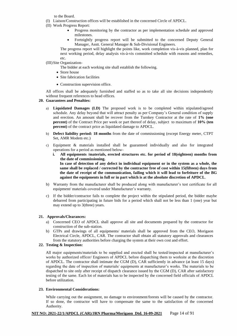
20. Guarantees and Penalties:
a) Liquidated Damages (LD) The proposed work is to be completed within stipulated/agreed
schedule. Any delay beyond that will attract penalty as per Company’s General condition of supply
and erection. An amount shall be recover from the Turnkey Contractor at the rate of 1% (one
percent) of the Contract Price per week or part thereof of delay, subject to maximum of 10% (ten
percent) of the contract price as liquidated damage to APDCL.
b) Defect liability period: 18 months from the date of commissioning (except Energy meter, CTPT
Set, AMR Modem etc.)
c) Equipment & materials installed shall be guaranteed individually and also for integrated
operations for a period as mentioned below-
i. All equipments /materials, erected structures etc. for period of 18(eighteen) months from
the date of commissioning.
In case of detection of any defect in individual equipment or in the system as a whole, the
same shall be replaced / corrected by the contractor free of cost within 15(fifteen) days from
the date of receipt of the communication, failing which it will lead to forfeiture of the BG
against the equipments in full or in part which is at the absolute discretion of APDCL.
b) Warranty from the manufacturer shall be produced along with manufacturer’s test certificate for all
equipment/ materials covered under Manufacturer’s warranty.
c) If the bidder/contractor fails to complete the project within the stipulated period, the bidder maybe
debarred from participating in future bids for a period which shall not be less than 1 (one) year but
may extend up to 3(three) years.
21. Approvals/Clearances:
a) Concerned CEO of APDCL shall approve all site and documents prepared by the contractor for
construction of the sub-station.
b) GTPs and drawings of all equipments/ materials shall be approved from the CEO, Morigaon
Electrical Circle, APDCL, CAR. The contractor shall obtain all statutory approvals and clearances
from the statutory authorities before charging the system at their own cost and effort.
22. Testing & Inspection:
All major equipments/materials to be supplied and erected shall be tested/inspected at manufacturer’s
works by authorized officer/ Engineers of APDCL before dispatching them to worksite at the discretion
of APDCL. The contractor shall intimate the CGM (D), CAR sufficiently in advance (at least 15 days)
regarding the date of inspection of materials/ equipments at manufacturer’s works. The materials to be
dispatched to site only after receipt of dispatch clearance issued by the CGM (D), CAR after satisfactory
testing of the same. Each lot of materials has to be inspected by the concerned field officials of APDCL
before utilization.
23. Environmental Considerations:
While carrying out the assignment, no damage to environment/forests will be caused by the contractor.
If so done, the contractor will have to compensate the same to the satisfaction of the concerned
Authority.

NIT NO: 2021-22/1/APDCL (CAR)/JRN Pharma/Morigaon Dtd. 16-09-2021 Page 15 of 91
24. Submission of documents
a) With bids.
i) Certificates and testimonials in support of credentials of the bidder’s organization.
ii) Details past experience along with present works in hand with awarded amount and progress
report.
iii) Brief writ-up on methodology to carry out the assignment, if awarded.
iv) Details of manpower to be engaged for the assignments.
v) Any other information, the bidder may feel facilitative in evaluating the bid.
vi) Copies of contractor and supervisor’s license, etc.
vii) Certificate from Registered Charted Accountant in support of Annual turn over
viii) Solvency certificate from the Bank.
ix) Earnest money deposit along with Techno- Commercial bid
x) Certificate in support of performance of the bidder.
b) During project execution
i) All documents for approval shall be submitted in 3 (three) copies.
ii) All final documents to be submitted to statutory organizations will be furnished as per requirement of
the authority.
25. Funding of the project: The proposed work is funded under Deposit scheme of APDCL.
26. The construction of line & Sub-stations for providing power supply to the proposed Cancer Care
Hospital, Morigaon is a Priority work of Govt. of Assam, hence, the work is to be executed with
high level of Quality standard of materials & labour and shall be completed within stipulated
time.
27. Ceiling on acceptance of Bid Value:
27.1. For Abnormally Low Bids (ALB) 27.1.1. An abnormally Low Bid is one in which the Bid price, in combination with other elements of the Bid, appears to be so low that it raises concerns as to the capability of the Bidder to perform the contract for the offered price. 27.1.2. For the purpose of identification and dealing with the ALBs, the MD, APDCL shall act as ex-officio Chairman of the Tender Evaluation Committee. The Committee shall undertake the following three-stage review process to check the possibility of an ALB by a potential successful bidder and take necessary action, as deemed fit. The decision of the Committee shall be conclusive and binding on all.
i. identify abnormally low costs and unit rates by comparing them with the APDCL estimate or other substantially responsive bidders, or recently awarded similar contracts; ii. clarify and analyze the Bidder’s resource inputs and pricing, including overheads, contingencies and profit margins; and iii. decide whether to accept or reject the Tender.
27.1.3. The ALBs shall be identified using any of the following 2(two) methodologies, as applicable: When Estimated Cost is disclosed: In this case, the ALB shall be identified based on the comparison with the Estimated Cost of the Project. The bids with quoted price below 10% (ten percent) of the Estimated Cost shall be treated as ALB by the Committee. When Estimated Cost is not disclosed: In this event, the Committee shall resort to a statistical approach in which first the Average Bid value shall be calculated among the substantially responsive bidders. Subsequently, the bids with quoted price found to be lower than 10% of the calculated average value shall be identified as ALBs. 27.1.4. Once a potential ALB has been identified, the Committee will seek a written explanation from the bidder of the reasons for the offered Tender price, including a detailed price analysis, proposed methodology, schedule, and allocation of risks and responsibilities. This may also include information regarding the economy of the manufacturing process; the services to be provided, or the construction method to be used; the technical solutions to be adopted; and any exceptionally favorable conditions available to the bidder for the works, equipment or services proposed. 27.1.5. Failure to furnish the required information against point 27.1.4 above within the stipulated time period will lead to the rejection of the bidder. In that case, the Committee will resort to the next lowest ranked bidder and reiterate the process, in case that bidder also happens to come under ALB. 27.1.6. On receiving the Bidder’s justification, the Committee will meticulously examine the information provided by the bidder while taking into account all the relevant evidence produced in response to the request for clarification. 27.1.7. After examining the explanation given and the detailed price analyses presented by the bidder, the Committee may at its sole discretion:
i) accept the Tender subject to requiring the bidder to submit an Additional Performance Security in pursuant to the Clause 27.2.1 under this section to protect the Employer from any financial loss in the event of default of the successful bidder under the contract; or ii) reject the Tender, if the evidence provided does not satisfactorily account for the low Tender price and make a similar determination for the next lowest ranked bid, if required.
27.2 Additional Performance Security in the event of ALB
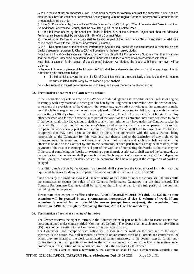
NIT NO: 2021-22/1/APDCL (CAR)/JRN Pharma/Morigaon Dtd. 16-09-2021 Page 16 of 91
27.2.1 In the event that an Abnormally Low Bid has been accepted for award of contract, the successful bidder shall be required to submit an additional Performance Security along with the regular Contract Performance Guarantee for an amount calculated as under: i) If the Bid Price offered by the shortlisted Bidder is lower than 10% but up to 20% of the estimated Project cost, then the Additional Performance Security shall be calculated @ 5% of the Contract Price. ii) If the Bid Price offered by the shortlisted Bidder is below 20% of the estimated Project cost, then the Additional Performance Security shall be calculated @ 15% of the Contract Price. iii) The additional Performance Security shall be treated as part of the Performance Security and shall be valid for a period coextensive with the Contract Performance Guarantee. 27.2.2 Non-submission of the additional Performance Security shall constitute sufficient ground to reject the bid and similar assessment pursuant to Clause 27.1 will be made for the next ranked bidder. Note that, if L1 is above the estimated value but accommodable with 3% Contingency & Sundries, then their Price offer shall be accepted. Otherwise negotiation shall be made with L1 Bidder to bring down to accommodable value. Note that, in case of tie (in respect of quoted price) between two bidders, the bidder with higher turn-over will be preferred. In the event of non-compliance of the following, APDCL shall have absolute discretion and right to scrap/reject the bid submitted by the successful bidder:
● If a bid contains several items in the Bill of Quantities which are unrealistically priced low and which cannot
be substantiated satisfactorily by the bidder in price analysis.
Non-submission of additional performance security, if required as per the terms mentioned above.
28. Termination of contract on Contractor’s default
If the Contractor neglects to execute the Works with due diligence and expertise or shall refuse or neglect
to comply with any reasonable order given to him by the Engineer in connection with the works or shall
contravene the provisions of the Contract, the owner may give notice in writing to the contractor to make
good the failure, neglect or contravention complained of. Shall the contractor fail to comply with the notice
within thirty (30) days from the date of serving the notice, then the Owner shall be at liberty to employ
other workmen and forthwith execute such part of the works as the Contractor, may have neglected to do or
if the owner shall think fit, without prejudice to any other right he may have under the Contract to take the
work wholly or in part out of the contractor's hands and re-contract with any other person or persons to
complete the works or any part thereof and in that event the Owner shall have free use of all Contractor's
equipment that may have been at the time on the site in connection with the works without being
responsible to the Contractor for fair wear and tear thereof and to the exclusion of any right of the
contractor over the same, and the Owner shall be entitled to retain and apply any balance which may
otherwise be due on the Contract by him to the contractor, or such part thereof as may be necessary, to the
payment of the cost of executing the said part of the work or of completing the Works as the case may be.
If the cost of completing the Works or executing a part thereof, as aforesaid, shall exceed the balance due to
the contractor, the contractor shall pay such excess. Such payment of excess amount shall be independent
of the liquidated damages for delay which the contractor shall have to pay if the completion of works is
delayed.
In addition, such action by the Owner, as aforesaid, shall not relieve the Contractor of his liability to pay
liquidated damages for delay in completion of works as defined in clause no.26 of GCSE.
Such action by the Owner as aforesaid, the termination of the Contract under this clause shall neither entitle
the contractor to reduce the value of the Contract Performance Guarantee nor the time thereof. The
Contract Performance Guarantee shall be valid for the full value and for the full period of the contract
including guarantee period.
Please note that as per the office order no. APDCL/OSD/MISC/2018-19/8 dtd. 14.11.2018, no time
extension will be granted in any circumstances irrespective of size & volume of work. If any
extension is needed for an unavoidable reason (except force majeure), the permission from
Chairman, APDCL through the Managing Director, APDCL will be mandatory.
29. Termination of contract on owners’ initiative
The Owner reserves the right to terminate the Contract either in part or in full due to reasons other than
those mentioned under clause entitled "Contractor's Default." The Owner shall in such an event give fifteen
(15) days notice in writing to the Contractor of his decision to do so.
The Contractor upon receipt of such notice shall discontinue the work on the date and to the extent
specified in the notice, make all reasonable efforts to obtain cancellation of all orders and contracts to the
extent they are related to the work terminated and terms satisfactory to the Owner, stop all further sub-
contracting or purchasing activity related to the work terminated, and assist the Owner in maintenance,
protection, and disposition of the Works acquired under the Contract by the Owner.
In the event of such a termination, the Contractor shall be paid compensation, equitable and

NIT NO: 2021-22/1/APDCL (CAR)/JRN Pharma/Morigaon Dtd. 16-09-2021 Page 17 of 91
reasonable, dictated by the circumstances prevalent at the time of termination.
If the Contractor is an individual or a proprietary concern and the individual or the proprietor dies and if the
contractor is a partnership concern and one of the partners dies then unless the Owner is satisfied that the
legal representatives of the individual contractor or of the proprietor of propriety concern and in the case of
partnership, the surviving partners, are capable of carrying out and completing the Contract, the Owner
shall be entitled to cancel the Contract as to its uncompleted part without being in any way liable to
payment of any compensation to the estate of deceased Contractor and/or to surviving partners of the
contractor's firm on account of the cancellation of the contract. The decision of the owner that the legal
representatives of the deceased contractor or surviving partners of the contractor's firm cannot carry out and
complete the contract shall be final and binding on the parties. In the event of such cancellation, the Owner
shall not hold the estate of the deceased Contractor and/or the surviving partner of the Contractor's firm
liable to damages for not completing the Contract.
30. Frustration of contract
In the event of frustration of the contract of supervening impossibility in items of Section 56 of the Indian
Contract Act, parties shall be absolved of their responsibility to perform the balance portion of the contract.
In the event of non-availability or suspension of funds for any reasons whatsoever (except for reason of
willful or flagrant breach by the Owner and/or contractor) then the Works under the contract shall be
suspended. Furthermore, if the Owner is unable to make satisfactory alternative arrangements for financing
to the contractor in accordance with the terms of the Contract within three months of the event, the parties
hereto shall be relieved from carrying out further obligations under the Contract treating it as frustration of
the Contract. In the event Performance Bank Guarantee, the parties shall mutually discuss to arrive at
reasonable terms on all issues including amounts due to either party for the work already done on
"Quantum merit" basis which shall be determined by mutual agreement between the parties.
31. Disclaimer:
While the Company will make every endeavor to extend necessary facilitation in expediting the work, the
contractor shall be responsible to organize and arrange all necessary inputs right from mobilization
activities up to completion of the project. Company will not entertain any failure / delay on such accounts.
Also, Company will not be responsible for any compensation, replenishment, damage, theft etc. as may be
caused due to negligent working, insufficient coordination with Government / non Government / Local
Authority by the contractor and/ or his personnel deputed for work. The contractor shall take necessary
insurance coverage under LIC/GIC etc. for his working personnel and the goods in store as well as in
transit. The contractor will be deemed to have made him acquainted with the local working conditions at
site(s) and fully provide for into the bid submitted.
32. Before submitting the tender, the intending bidders are requested to physically survey/inspect the
location/route and the scope of work and have discussion with concerned Sub-divisional Engineer
/Asstt. General Manager in this regard in order to minimize issues after awarding the contract.
Any additional work/quantity which may be required for laying / renovation of the line but
inadvertently left out in the BOQ may be raised in the pre-bid meeting only.
33. No pre-bid discussion will be held. Instead of physical meeting, intending bidders may submit
their Pre-bid Queries if any via e-mail at [email protected] from 10:00 Hrs. of
21.09.2021 to 16:00 Hrs. of 21.09.2021.
34. Terms and conditions, which are not specified herein above will be governed by the APDCL’s
General Conditions of supply and erection in force.
35. During the course of execution of the project, if any requirement of additional work arises which
happens to be not in scope of the BOQ and primarily involves permission from other
State/Central department in regard to Railway track crossing or Highway crossing, then
obtaining such necessary permission will be the obligation to the Turn key Contractor. APDCL,
however shall bear the essential financial involvement required in this process, if any.
36. APDCL’s General Conditions of supply and erection (GCSE) may be seen in our official website
www.apdcl.org.

NIT NO: 2021-22/1/APDCL (CAR)/JRN Pharma/Morigaon Dtd. 16-09-2021 Page 18 of 91
Annexure – I (A)
Tender Proforma part – I (Techno-commercial Bid)
NIT NO: 2021-22/1/APDCL (CAR)/JRN Pharma/Morigaon Dtd. 16-09-21
a. Name and full address of the Bidder :
b. Particulars of payment made for Purchase of
tender document in the shape of. :
c. Amount of earnest money paid in the shape of :
d. Whether Sales Tax Clearance Certificate : Yes / No
Submitted
e. GST Registration. .:
f. Acceptance of guarantee clause of :
Materials /equipment and system
Installed individually and for integrated
Operation.
g. Acceptance of penalty clause :
h. Acceptance of terms of payment :
i. Certificate/ documents regarding adequate :
experience of doing similar job
j. Details of work presently in hand with amount :
(Awarded by APDCL and other successor
Companies of ASEB) - a separate sheet if
Required may be enclosed.
k. Details of manpower and T&Ps including :
Vehicles available with the firm to be
Enclosed separately.
l. List of documents enclosed :
a) ….
b) ….
c) ….
Signature with full name
and designation of bidder or
his/her authorized representative
with seal

Page 19 of 91
Annexure- I (B)
REQUIRED QUALIFICATION
Sl
No. Qualification Requirement
Furnished at
Annexure Page Remark
A LEGAL
1 Document in support of legal status of firm
2 Memorandum of Association & Registered / Notarised Joint venture
Agreement if JV
3 Registered / Notarised power of attorney of the signatory of the Bidder
to participate in the Bid in case of JV
4 Board resolution of the company to authorizing the signatory in case of
company
5
Information regarding any litigation, current or during the last five years,
in which the Bidder is involved, the parties concerned, and disputed
amount
6 Valid Electrical Contractor's License
7 Valid Electrical & Supervisory License
8 Labour License
9 GST Registration Certificate
10 Provident Fund Registration Certificate
11 List of labour registered under Assam building and other construction
Workers’ Welfare Board
12 ESIC Registration Certificate
B Financial
1 Audited Balance sheet, Profit & Loss account, Auditor’s report for last
three year [FY 2018-19, FY 2019-20 & FY 2020-21( audited or Prov.)]
2 CA Certified Turnover of bidder during the last 3(three) years. [i.e. (FY
2018-19, FY 2019-20 & FY 2020-21(audited or Prov.)]
3 Evidence of adequacy of working capital for this contract (access to
Letter of Credit and availability of other financial resources)
4 Authority to seek references from the Bidder's Bankers
5 Income Tax return for last 3 (three) years i.e. [FY 2018-19, FY 2019-20
& FY 2020-21(audited or Prov.)]
6 Value of similar work performed by the bidder in each of the last five
years – Statement
7 Proposals for subcontracting components of the Works amounting to
more than 10 percent of the Contract Price
8 Details of the Bank Guarantee as EMD (BG/TD/Bank Call Deposit)
C Technical ability and experience
1
Experience in works of a similar nature and volume for each of the last
5(five) years from the closing date of Techno-Commercial Bid and
details of works under way or contractually committed including full
address of client for communication- Statement
2
Certificates issued by an Engineer not below the Cadre of Deputy
General Manager/SE along with supporting photo-copies of agreements
for the works executed.
3
Detailed activity plan and methodology supported with layout and
necessary drawings and calculations (detailed) to allow the employer to
review their proposals.
4 Quality Assurance plan with Bar Chart
5 List of technical personnel and their qualification and experience with
organization chart
6 Proof of availability of the tools, tackles, spare parts, etc. for carrying out
the works.

Page 20 of 91
D Technical particulars of equipments and Materials offered in the Bill
of Material and their GTPs
LIST OF ONGOING & COMPLETED PROJECTS: ANNEXURE- I(C)
List of ongoing & completed projects of -
(i) APDCL & Other successor companies of ASEB &
(ii) works executed outside the state of Assam
Sl. No. Name of the work Order No Contract
value Scheme
Stipulated
date of
completion
Present
Status
1
2
3
BIDDER’S INFORMATION SHEET: Annexure- I (D)
Bidder’s Information
Bidder’s legal name
In case of JV, legal name
of each partner
Bidder’s country of
constitution
Bidder’s/Firm year of
constitution
Bidder’s legal address in
country of constitution
Bidder’s authorized
representative
(name, address, telephone
numbers, fax numbers, e-
mail address)
Attached are copies of the following original documents.
1. In case of single entity, articles of incorporation or constitution of the legal entity.
2. Authorization to represent the firm or JV named in above, in accordance with clause stated in the Bid
document.
3. In case of JV, letter of intent to form JV or JV agreement, in accordance with clause stated in the Bid
document.

Page 21 of 91
………………………..
……………………….
Signature, name and designation of
Authorised Signatory
For and on behalf of
…………………………….(Name ofthe
Bidder)
Place : Date:
FINANCIAL SITUATION (FIN-1)
Each bidders or member of JV must fill in this form
Financial Data for Previous 3 Years [Rs in lakhs]
Year 1: FY 2018-19 Year 2: FY 2019-20 Year 3: FY 2020-
21(Audited or Prov.)
Information from Balance Sheet
Total Assets
Total Liabilities
Net Worth
Current Assets
Current Liabilities
Information from Income Statement
Total Revenues
Profits Before Taxes
Profits After Taxes
❑ Attached are copies of financial statements (balance sheets including all related notes, and income
statements) for the last three years, as indicated above, complying with the following conditions.
• All such documents reflect the financial situation of the Bidder or partner to a JV, and not sister or
parent companies.
• Historic financial statements must be audited by a certified accountant.
• Historic financial statements must be complete, including all notes to the financial statements.
• Historic financial statements must correspond to accounting periods already completed and audited (no
statements for partial periods shall be requested or accepted).
Form FIN - 2: Average Annual Turnover

Page 22 of 91
Each Bidder or member of a JV must fill in this form.
Annual Turnover Data for the Last 3 Years
Year Amount (Rs. In lakhs)
FY 2018-19
FY 2019-20
FY 2020-21(Audited or Prov.)
Average Annual Turnover
The information supplied shall be the Annual Turnover of the Bidder or each member of a JV in terms of the amounts billed
to clients for each year for contracts in progress or completed in ₹(Rupees).
Form FIN – 3: Financial Resources
Specify proposed sources of financing, such as liquid assets, unencumbered real assets, lines of credit, and other financial
means, net of current commitments, available to meet the total construction cash flow demands of the subject contract or
contracts as indicated in Section 3 (Evaluation and Qualification Criteria)
Financial Resources
No. Source of financing Amount (Rs. In lakhs)
1
2
3

Page 23 of 91
SECTION III
BILL OF QUANTITY (BOQ)

Page 24 of 91
BoQ
WORKS: “Construction of 33 KV bay with terminal equipments at 33/11 KV Nellie Substation, Construction of 33/.433 KV 2
MVA Sub Stations at JRN Pharma & Laboratories LLP at Borgaon,Killing Valley,Morigaon Campus,Construction of 33 KV
Line with MVCC from 33/11 KV Nellie Substation to 33/0.433 KV 2 MVA Substation under Jagiroad Electrical Sub Division
of Morigaon Electrical Circle, APDCL”
BoQ - 1
Construction of 33KV bay with terminal equipment at 33/11KV Nellie Sub Station for providing power supply to JRN Pharma & Laboratories LLP under deposit work scheme.
S/L Item description Qty Unit
1 33KV VCB with GI mounting structure 1 Set
2 33 KV 1 phase CT with GI mounting structure & Marshalling box (set comprising of three units) 200-100/5-5 A
1 Set
3 33 KV Isolator with Earth switch and with GI mounting structure 4 Nos.
4 33 KV 10 KA Lighting arrestor with surge Monitor & GI Mounting structure
2 Nos.
5 33 KV C&R panel for feeder ( with numerical relay & static TVM) 1 Nos.
6 33 KV Combined CT-PT set, 50/5 amps 1 Nos.
7 Control cable copper 10 core x 2.5 sq mm 50 Mtr
8 Control cable copper 7 core x 2.5 sq mm 350 Mtr
9 Control cable copper 4 core x 2.5 sq mm 350 Mtr
10 33 KV XLPE cable,1 core,240 sq mm,Aluminium ( armoured) 750 Mtr
11 33 KV Cable Kit for XLPE,single core 240 sq mm ( outdoor) 10 Nos.
12 HT Trivector meter 1 Nos.
13 GI Lattice structure 10 M/T
14 GI strip size 50x6 mm 120 Mtr
15 33 KV Pin Insulator Polymer 9 Nos.
16 33 KV Polymeric Disc Insulator 90 KN 18 Nos.
17 Hardware fiiting fir disc Insulator 18 Nos.
18 33 KV Post Insulator 6 Nos.
19 ACSR Panther Conductor Bus bar & Jumpering 0.2 Km
20 ACSR Wolf Conductor 0.15 Km
21 PG Clamp for Panther conductor 20 Nos.
22 PG clamp for Wolf conductor 20 Nos.
23 PVC 4'' Supreme brand pipe 4 Kg pressure 100 Mtr
24 Metering cabinet 1 Nos.
25 Modem for sending end meter 1 Nos.
26 GI Nuts and Boltswitch washer 150 Kg.
27 RCC foundation for Isolator (Set) 4 Job
28 RCC foundattion for VCB ( Set) 1 Job
29 PCC foundation ( 1:2:4 ) for LA,CT,PT and Lattice structure 11 Job
30 Switchyard gravelling of 0.15 mtr ( thickness) by 40 mm size crushed 400 Job
31 Transformer pad for station transformer 1 Job
32 Installation of Earthing system with MS flat 50x10 mm for mat and 25x6 mm flat for riser with 50 mm GI electrode of length 3 mtr etc
400 Job

Page 25 of 91
BoQ - 2
Construction of 33/0.433KV, 2MVA Sub Station for providing power supply to JRN Pharma & Laboratories LLP at Borgaon, P.O. Killing Valley, Dist :Morigaon under deposit work scheme.
S/L Item description Qty Unit
1 2000 KVA,33/0.433 KV,Dry Type Cast Resin Tranformer 1 Nos.
2 33 KV 1 -Phase CT with GI mounting structure & Marshalling box (set comprising of three units) 200-100/5-5 A
1 Set
3 33KV/110V, 1-Phase PT with GI mounting Structure & Marshaling box(Set comprising of three units)
1 Set
4 33 KV Isolator with Earth Switch and with GI mounting Structure 800A
1 Nos.
5 33KV 10KA Lightning Arrester with Surge Monitor & GI mounting Structure
1 Nos.
6 33KV Comboined CT-PT set, 50/5 Amps 1 Nos.
7 Metering Cabinate 1 Nos.
8 Modem for sending end meter 1 Nos.
9 CI Earth Pipe 1.6m, inner dia100mm, Outer dia 110mm 2 Nos.
10 Control Cable copper 10core x 2.5sq mm 50 Mtr
11 Control Cable copper 4core x 2.5sq mm 350 Mtr
12 Control Cable copper 7core x 2.5sq mm 350 Mtr
13 33KV XLPE Cable, 1-core, 240sq mm, Aluminium, (Armoured) 3000 Mtr
14 33KV Cable Kit for XLPE, single core, 240sq mm( Outdoor) 10 Nos.
15 33KV Cable Kit for XLPE, single core, 240sq mm( Indoor) 20 Nos.
16 HT Trivector meter 1 Nos.
17 GI Steel Tubler Pole SP-76 10 Nos.
18 33 KV Pin insulator Polymer 12 Nos.
19 33KV Polymeric Disc Insulator 90KN 24 Nos.
20 H/W Fitting for Disc insulator 24 Nos.
21 33KV Post Insulator 12 Nos.
22 ACSR Wolf Conductor 0 Km
23 GI Strip size 50x6mm 120 Mtr
24 GI Nuts and Boaltswith washer 150 Kg.
25 33KV, 800A Indoor VCB panel 1 Nos.
26 Battery Charger suitable for 100AH, 110V battery bank 1 Nos.
27 DCDB 1 Nos.
28 100AH, 110V maintanance free battery bank 1 Nos.
29 PG clamp for Panthar 20 Nos.
30 PG clamp for Woolf 20 Nos.
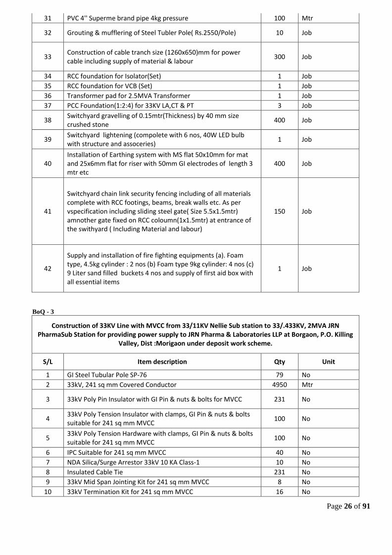
Page 26 of 91
31 PVC 4'' Superme brand pipe 4kg pressure 100 Mtr
32 Grouting & mufflering of Steel Tubler Pole( Rs.2550/Pole) 10 Job
33 Construction of cable tranch size (1260x650)mm for power cable including supply of material & labour
300 Job
34 RCC foundation for Isolator(Set) 1 Job
35 RCC foundation for VCB (Set) 1 Job
36 Transformer pad for 2.5MVA Transformer 1 Job
37 PCC Foundation(1:2:4) for 33KV LA,CT & PT 3 Job
38 Switchyard gravelling of 0.15mtr(Thickness) by 40 mm size crushed stone
400 Job
39 Switchyard lightening (compolete with 6 nos, 40W LED bulb with structure and assoceries)
1 Job
40 Installation of Earthing system with MS flat 50x10mm for mat and 25x6mm flat for riser with 50mm GI electrodes of length 3 mtr etc
400 Job
41
Switchyard chain link security fencing including of all materials complete with RCC footings, beams, break walls etc. As per vspecification including sliding steel gate( Size 5.5x1.5mtr) amnother gate fixed on RCC coloumn(1x1.5mtr) at entrance of the swithyard ( Including Material and labour)
150 Job
42
Supply and installation of fire fighting equipments (a). Foam type, 4.5kg cylinder : 2 nos (b) Foam type 9kg cylinder: 4 nos (c) 9 Liter sand filled buckets 4 nos and supply of first aid box with all essential items
1 Job
BoQ - 3
Construction of 33KV Line with MVCC from 33/11KV Nellie Sub station to 33/.433KV, 2MVA JRN PharmaSub Station for providing power supply to JRN Pharma & Laboratories LLP at Borgaon, P.O. Killing
Valley, Dist :Morigaon under deposit work scheme.
S/L Item description Qty Unit
1 GI Steel Tubular Pole SP-76 79 No
2 33kV, 241 sq mm Covered Conductor 4950 Mtr
3 33kV Poly Pin Insulator with GI Pin & nuts & bolts for MVCC 231 No
4 33kV Poly Tension Insulator with clamps, GI Pin & nuts & bolts suitable for 241 sq mm MVCC
100 No
5 33kV Poly Tension Hardware with clamps, GI Pin & nuts & bolts suitable for 241 sq mm MVCC
100 No
6 IPC Suitable for 241 sq mm MVCC 40 No
7 NDA Silica/Surge Arrestor 33kV 10 KA Class-1 10 No
8 Insulated Cable Tie 231 No
9 33kV Mid Span Jointing Kit for 241 sq mm MVCC 8 No
10 33kV Termination Kit for 241 sq mm MVCC 16 No

Page 27 of 91
11 G I Channel (100x50x6x3200mm) 82 No
12 GI Angle (50x50x6) mm 468 Mtr
13 Pole Clamp GI Flat 50x6 mm 250 No
14 CI Earth Pipe 1.6m, inner dia100mm, Outer dia 110mm 79 Nos.
15 GI Wire 6 SWG 45 Kg
16 GI Nuts & Bolts 120 Kg

Page 28 of 91
SECTION-IV
GENERAL REQUIREMENT

Page 29 of 91
GENERAL REQUIREMENTS
The bidder shall comply with the following general requirements along with other specifications.
1.0 QUALITY ASSURANCE PLAN
1.1 The bidder shall invariably furnish the following information along with his offer failing which the offer shall be
liable for rejection. Information shall be separately given for individual type of equipment offered.
i) The structure of organization
ii) The duties and responsibilities assigned to staff ensuring quality of work
iii) The system of purchasing, taking delivery and verification of materials
iv) The system for ensuring quality of workmanship
v) The quality assurance arrangements shall confirm to the relevant requirement of ISO 9001 on ISO 9002 as
applicable.
vi) Statement giving list of important raw materials, names of sub-supplies for the raw materials, list of
standards according to which the raw material are tested, list of tests normally carried out on raw material
in the presence of suppliers representative, copies of test certificates.
vii) Information and copies of test certificates as on (i) above in respect of bought out items
viii) List of manufacturing facilities available
ix) Level of automation achieved and list of areas where manual processing exists.
x) List of areas in manufacturing process, where stage inspections are normally carried out for quality control
and details of such test and inspection.
xi) List of testing equipment available with the bidder for final testing of equipment specified and test plant
limitation, if any vis-à-vis the type. Special acceptance and routine tests specified in the relevant
standards. These limitations shall be very clearly brought out in "Schedule of Deviations" from the
specified test requirement.
1.2 The contractor shall within 30 days of placement of order, submit the following information to the
purchaser.
i) List of the raw material as well as bought out accessories and the names of sub-suppliers selected from
those furnished along with the offer.
ii) Type test certificated of the raw material and bought out accessories if required by the purchaser.
iii) Quality Assurance Plant (QAP) with hold points for purchaser’s inspection. QAP and purchasers hold
points shall be discussed between the purchaser and contractor before the QAP is finalized.
The contractor shall submit the routine test certificates of bought out accessories and central excise asses for raw
material at the time of routine testing if required by the purchaser and ensure that the quality assurance
requirements of specification are followed by the sub-contractor.
1.3 The Quality Assurance Programmed shall give a description of the Quality System and Quality Plans
with the following details-
i) Quality System
• The structure of the organization.
• The duties and responsibilities assigned to staff ensuring quality of work.
• The system of purchasing, taking delivery of verification of materials
• The system of ensuring of quality workmanship.
• The system of control of documentation.
• The system of retention of records.
• The arrangement of contractor internal auditing.
• A list of administrator and work procedures required to achieve contractor’s quality requirements. These
procedures shall be made readily available to the purchaser for inspection on request.
ii) Quality Plans
• An outline of the proposed work and program sequence.
• The structure of contractor’s organizations for the contract.
• The duties and responsibilities ensuring quality of work.
• Hold and notification points.
• Submission of engineering documents required by this specification.
• The inspection of the materials and components on request.
• Reference to contractor’s work procedures appropriate to each activity.
• Inspection during fabrication /construction.
• Final inspection and test.
2.0 Inspection
2.1 The Owner's representative or third party nominee shall at all times be entitled to have access to the works and all
places of manufacture, where insulator, and its component parts shall be manufactured and the representatives
shall have full facilities for unrestricted inspection of the Contractor's and sub-Contractor's works, raw materials,
manufacture of the material and for conducting necessary test as detailed herein.
2.2 The material for final inspection shall be offered by the Contractor only under packed condition as detailed in the
specification. The Owner shall select samples at random from the packed lot for carrying out acceptance tests.
Page 30 of 91
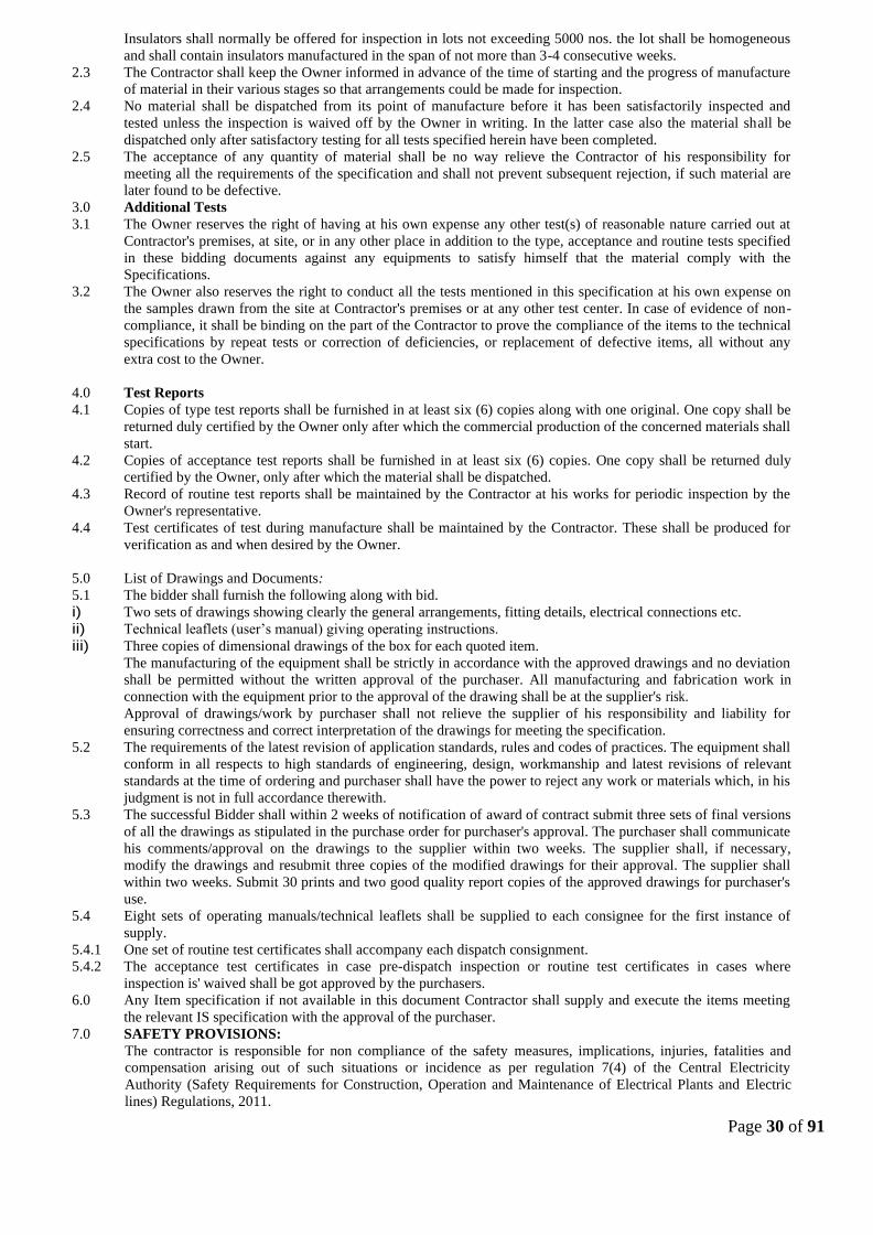
Insulators shall normally be offered for inspection in lots not exceeding 5000 nos. the lot shall be homogeneous
and shall contain insulators manufactured in the span of not more than 3-4 consecutive weeks.
2.3 The Contractor shall keep the Owner informed in advance of the time of starting and the progress of manufacture
of material in their various stages so that arrangements could be made for inspection.
2.4 No material shall be dispatched from its point of manufacture before it has been satisfactorily inspected and
tested unless the inspection is waived off by the Owner in writing. In the latter case also the material shall be
dispatched only after satisfactory testing for all tests specified herein have been completed.
2.5 The acceptance of any quantity of material shall be no way relieve the Contractor of his responsibility for
meeting all the requirements of the specification and shall not prevent subsequent rejection, if such material are
later found to be defective.
3.0 Additional Tests
3.1 The Owner reserves the right of having at his own expense any other test(s) of reasonable nature carried out at
Contractor's premises, at site, or in any other place in addition to the type, acceptance and routine tests specified
in these bidding documents against any equipments to satisfy himself that the material comply with the
Specifications.
3.2 The Owner also reserves the right to conduct all the tests mentioned in this specification at his own expense on
the samples drawn from the site at Contractor's premises or at any other test center. In case of evidence of non-
compliance, it shall be binding on the part of the Contractor to prove the compliance of the items to the technical
specifications by repeat tests or correction of deficiencies, or replacement of defective items, all without any
extra cost to the Owner.
4.0 Test Reports
4.1 Copies of type test reports shall be furnished in at least six (6) copies along with one original. One copy shall be
returned duly certified by the Owner only after which the commercial production of the concerned materials shall
start.
4.2 Copies of acceptance test reports shall be furnished in at least six (6) copies. One copy shall be returned duly
certified by the Owner, only after which the material shall be dispatched.
4.3 Record of routine test reports shall be maintained by the Contractor at his works for periodic inspection by the
Owner's representative.
4.4 Test certificates of test during manufacture shall be maintained by the Contractor. These shall be produced for
verification as and when desired by the Owner.
5.0 List of Drawings and Documents:
5.1 The bidder shall furnish the following along with bid.
i) Two sets of drawings showing clearly the general arrangements, fitting details, electrical connections etc.
ii) Technical leaflets (user’s manual) giving operating instructions.
iii) Three copies of dimensional drawings of the box for each quoted item.
The manufacturing of the equipment shall be strictly in accordance with the approved drawings and no deviation
shall be permitted without the written approval of the purchaser. All manufacturing and fabrication work in
connection with the equipment prior to the approval of the drawing shall be at the supplier's risk.
Approval of drawings/work by purchaser shall not relieve the supplier of his responsibility and liability for
ensuring correctness and correct interpretation of the drawings for meeting the specification.
5.2 The requirements of the latest revision of application standards, rules and codes of practices. The equipment shall
conform in all respects to high standards of engineering, design, workmanship and latest revisions of relevant
standards at the time of ordering and purchaser shall have the power to reject any work or materials which, in his
judgment is not in full accordance therewith.
5.3 The successful Bidder shall within 2 weeks of notification of award of contract submit three sets of final versions
of all the drawings as stipulated in the purchase order for purchaser's approval. The purchaser shall communicate
his comments/approval on the drawings to the supplier within two weeks. The supplier shall, if necessary,
modify the drawings and resubmit three copies of the modified drawings for their approval. The supplier shall
within two weeks. Submit 30 prints and two good quality report copies of the approved drawings for purchaser's
use.
5.4 Eight sets of operating manuals/technical leaflets shall be supplied to each consignee for the first instance of
supply.
5.4.1 One set of routine test certificates shall accompany each dispatch consignment.
5.4.2 The acceptance test certificates in case pre-dispatch inspection or routine test certificates in cases where
inspection is' waived shall be got approved by the purchasers.
6.0 Any Item specification if not available in this document Contractor shall supply and execute the items meeting
the relevant IS specification with the approval of the purchaser.
7.0 SAFETY PROVISIONS:
The contractor is responsible for non compliance of the safety measures, implications, injuries, fatalities and
compensation arising out of such situations or incidence as per regulation 7(4) of the Central Electricity
Authority (Safety Requirements for Construction, Operation and Maintenance of Electrical Plants and Electric
lines) Regulations, 2011.

Page 31 of 91
1. All the electrical installation works including additions, alternations, repairs and adjustments to existing
installations shall be carried out by an electrical contractor licensed in this behalf by the state government
and under direct supervision of a person holding a valid certificate of electrical competency and by a person
holding a valid workman permit issued or recognized by the Government.
2. All the aforesaid electrical works at site shall be carried by engaging competent & designated person having
valid electrical workman permit issued or recognised by the Govt. of Assam.
3. The Contractor shall furnish list of designated and competent persons having valid electrical workman
permits before execution of the electrical works at site to APDCL.
4. The contractor shall maintain a register of designated persons wherein the names of the designated persons
and purpose for which they are designated shall be entered along with their valid registered electrical
workman permit or certificate number.
5. The register of designated persons shall be produced before competent officials of APDCL/Electrical
Inspector when required by him for verification or removal of names from the aforesaid register on direction
by an electrical Inspector.
6. No person shall work on lines and apparatus and no person assist such person unless he is designated in this
behalf and takes safety precautions as per the safety Regulations of CEA..
7. Only persons designated in this behalf by the APDCL shall be allowed to carry out works on live lines and
apparatus of APDCL.
8. In the event of any electrical accident occurring due to use of poor quality/sub-standard material/item
or due to poor workmanship on the part of the contractor/supplier leading to death or injury of any
person or livestock/animal, the contractor/supplier shall be held responsible and shall be liable to pay
compensation for the same.
In such, APDCL may at its discretion debar the concerned contractor/supplier from participating in
any future bid for such period deemed fit without prejudice to its authority to take any other legal
action.

Page 32 of 91
SECTION – 5
FORMS OF BID

Page 33 of 91
PROFORMA OF BANK GUARANTEE FOR EARNEST MONEY
(To be stamped in accordance with Stamp Act)
The non-Judicial stamp paper shall be in the name of issuing bank
Ref………………………….. Bank Guarantee No…………..
Date…………………….
To
The Chief General Manager (D&S),CAR
Assam Power Distribution Company Ltd.
Bijulee Bhawan, Paltanbazar
Guwahati-1
Dear Sirs/ Madam,
In accordance with invitation to bid under your Bid No………………. M/s………………. having its Registered/
Head Office at ……………..( hereinafter called the ‘Bidder’) wish to participate in the said Bid or ………………… and
you, as a special favour have agreed to accept an irrevocable and unconditional Bank Guarantee for an amount of
……………….. valid up to……………………. On behalf of Bidder in lieu of the Earnest Money deposit of the BID
required to be made by the bidder, as a condition precedent for participation in the said Bid.
We, the …………………. Bank at …………………… have our Head Office at…………..( local address) guarantee and
undertake to pay immediately on demand by Assam Power Distribution Company Limited, the Amount of
……………………………………………
…………………………………………………..( in words & figures) without any reservation, protest, demur and recourse.
Any such demand made by said ‘Owner’ shall be conclusive and
binding on us irrespective of any dispute or difference raised by the Bidder.
The Guarantee shall be irrevocable and shall remain valid up to and including …………..@....................... if any further
extension of this guarantee is required, the same shall be extended to such required period ( not exceeding one year) on
receiving instruction from M/s ………… … ………. on whose behalf this guarantee is issued.
In witness whereof the Bank, through its authorized office, has set its hand and stamp on this
…………… day of ………………….. 20………… at …………………………
WITNESS
……………………… …………………….
(Signature) ( Signature)
…………………….. ……………………
(Name) (Name)
……………………. ……………………
( Official Address) (Official Address)
@ This date shall be thirty (30) days after the last date for which the bid is valid.

Page 34 of 91
PROFORMA OF BANK GUARANTEE FOR CONTRACT PERFORMANCE
(To be stamped in accordance with Stamp Act)
Ref………………………….. Bank Guarantee No…………..
Date…………………….
To
The Chief General Manager (D&S), CAR
Assam Power Distribution Company Ltd.
Bijulee Bhawan, Paltanbazar
Guwahati-1
Dear Sirs/ Madam,
In consideration of Assam Power Distribution Company Ltd., (herein after referred to as the ‘Owner’ which
expression shall unless repugnant to the context or meaning thereof include its successors, administrators and assigns) having
awarded to M/s…………… ….……………………….with registered/ Head office at ……………….( hereinafter referred to
as “ Contractor” which expression shall unless repugnant to the context or meaning thereof include its successors,
administrators, executors and assigns), a Contract by issue of Owner’s Letter of Intent No…………… dated………………..
and the same having been acknowledged by the contractor, resulting in a contract and contractor having agreed to provide a
Contract Performance Guarantee for the faithful performance of the entire Contract equivalent to 10(%) of the said value
Contract to the Owner.
We………………………………………………………………………………………….. (Name & Address) having its Head
Office at …………………( hereinafter referred to as the “ Bank” , which expression shall, unless repugnant to the context or
meaning thereof, include its successors, administrators, executors and assigns) do hereby guarantee and undertake to pay the
owner, on demand any or all monies payable by the contractor to be extent of ₹ …………………. at any time up to
………………………..**( day/month/year) without any demur, reservation , contest , recourse or protest and / or without
any reference to this contractor. Any such demand made by the owner on the bank shall be conclusive and binding
notwithstanding any difference between the Owner the Contractor or any dispute pending before any Court, Tribunal,
Arbitrator or any other authority. The bank undertakes not to revoke this guarantee during its currency without previous
consent of the owner and further agrees that the guarantee herein contained shall continue to be enforceable till the owner
discharges this guarantee.
The Owner shall have the fullest liberty without affecting in any way the liability of the Bank under the guarantee, from time
to time to extend the time for performance or the contract by the contractor. The owner shall have the fullest liberty, without
affecting this guarantee, to postpone from time to time the exercise of any power vested in them or of any right which they
might have against the contractor, and to exercise the same at any time in any matter, and either to enforce or to for bear to
enforce any covenants, contained or implied, in the contract between the owner and the contractor or any other course or
remedy or security available to the owner. The Bank shall not be released to its obligations under these presents by any
exercise by the owner of its liberty with reference to the matters aforesaid or any of them or by reason of any other act of
omission or commission on the part of the owner or any other indulgences shown by the owner or by any other matter or
thing whatsoever which under law would, but for this provision have the effect of relieving the Bank.
The bank also agrees that the owner at its option shall be entitled to enforce this guarantee against the Bank as a principal
debtor, in the first instance without proceeding against the contractor and not withstanding any security or other guarantee
the owner may have in relation to the Contractor’s liabilities.
Notwithstanding anything contained herein above our liability under this guarantee is restricted to ……………………. And
it shall remain in force up to an including …………………….. and shall be extended from time to time for such period( not
exceeding 1 year) as may be desired by M/s………………………………………………………….on whose behalf this
guarantee has been given.
Dated this……………………. Day of ……………………….. 20……………… at…………
WITNESS
……………………………. ………………………

Page 35 of 91
(Signature) (Signature)
…………………………… ……………………..
(Name) (Name)
………………………….. ……………………..
(Official address) (Official address)
Attorney as per power
Of Attorney No…………..
Date……………………..
NB: The stamp paper of appropriate value shall be purchased in the name of issuing bank.

Page 36 of 91
PROFORMA OF EXTENSION OF BANK GUARANTEE
Ref………………………….. Date…………………….
To
The Chief General Manager (D&S),CAR
Assam Power Distribution Company Ltd.
Bijulee Bhawan, Paltanbazar
Guwahati-1
Dear Sirs/ Madam,
Sub: Extension of Bank Guarantee No……………….. for Rs…………………. Favouring yourselves , expiring on
…………………. On account of M/S………………………….. in respect of contract no……………………. dated
…………….. (Hereinafter called original Bank Guarantee).
At the request of M/s ……………………… we …………………… bank, branch office at ………………….. and having its
Head Office at ………………………. Do hereby extend our liability under the above mentioned Bank Guarantee
No………………… dated………………………for a further period of ……………………… (Years / Months)
from………………….. to expire on………………….. expect as provided above, all other terms and conditions of the original
Bank Guarantee No………………………. dated ………………. Shall remain unaltered and binding.
Please treat this as an integral part of the original Bank Guarantee to which it would be attached.
Yours faithfully
For………………………………
Manager/ Agent/Accountant …………………..
Power of attorney No……………………
Dated……………………………………
SEAL OF BANK
Note: The non-judicial stamp paper of appropriate value shall be purchased in the name of the Bank who has issued the Bank
Guarantee.

Page 37 of 91
PROFORMA OF “AGREEMENT”
(To be executed on non-Judicial stamp paper)
This Agreement made this …………….. day of ………… two thousand……………. Between Assam Power Distribution
Company Ltd. having its head office at Bijulee Bhawan, Paltanbazar, Guwahati-1 ( hereinafter referred to as ‘Owner’ or
‘APDCL’, which expression shall include its administrators, successors and assign on one part and (hereinafter referred to as
the ‘Contractors ‘X’ ( Name of the contracting Co.) which expression shall include its administrators, successors, executors and
permitted assigns) on the other part.
WHEREAS APDCL desirous of …………………….. in ……………. Circle associated with APDCL at
……………….(District) invited Bids for…………………………………………….. ………………………………. (Briefly
describe scope of works) for the first state of the project as per its Bid Specification No………………………………
AND WHEREAS……………………….”X” ………………………. Had participated in the above referred Bidding vide their
proposal No……………………. dated………………. And awarded the Contract to……………..” X”…………….. on terms
and conditions documents referred to therein which have been acknowledged by……………….”X”…………………..resulting
into a “Contract”
NOW THEREFORE THIS DEED WITNESS AS UNDER:-
1.0 Article
1.1 Award of Contract
APDCL awarded the contract to……………..”X”……………… for the work of …………… on the terms and conditions
contained in its letter of Award No…….. ………. Dated…………… and the documents referred to therein. The award has
taken effect from aforesaid letter of award. The terms and expression used in this agreement shall have the same meaning as are
assigned to them in the ‘Contract Documents’ referred to in this succeeding Article.
2.0 Documentation
2.1 The contract shall be performed strictly as per the terms and condition stipulated herein and in the following documents
attached herewith( hereinafter referred to as “Contract Documents”.)
i) Section 1-11 of the Bidding Document.
ii) Proposal Sheets, Data Sheets, Drawing work schedule submitted by “X”.
APDCL’s Letter of Award No………….. dated……………….duly acknowledged by “X”.
Quality Plans for manufacturing and field activities entitled as Quality Plan.
All the aforesaid Contract Documents shall form an integral part of this agreement , in so far as the same or any part conform to
the bidding documents and what has been specifically agreed to by the Owner in its letter of Award. Any matter inconsistent
therewith, contrary or repugnant thereto or any deviations taken by the Contractor in its ‘Proposal’ but not agreed to specially
by the Owner in its Letter of Award shall be deemed to have been withdrawn b y the Contractor. For the sake of brevity, this
agreement along with its aforesaid Contract Documents shall be referred to as the ‘Agreement’.
3.0 Conditions & Covenants
3.1 The scope of Contract, Consideration, Terms of Payment, Price Adjustments, Taxes wherever applicable, Insurance,
Liquidated Damage, Performance Guarantees and all other terms and conditions are contained in APDCL’s Letter of Award
No………........... dated……………… read in conjunction with other aforesaid contract documents. The contract shall be duly
performed by the Contract Documents, but which are needed for successful, efficient, safe and reliable operation of the
equipment unless otherwise specifically excluded in the specification under ‘exclusion’ or Letter of Award.
3.2 The scope of work shall also include supply and installation of all such items which are not specifically mentioned in the
contract Documents, but which are needed for successful, efficient, safe and reliable operation of the equipment unless
otherwise specifically excluded in the specifications under ‘exclusions’ or ‘Letter of Award’.
3.3 Time Schedule
3.3.1 Time is the essence of the Contract and schedules shall be strictly adhered to “X” shall perform the work in accordance
with the agreed schedules.
3.4 Quality Plans
3.4.1 The Contractor is responsible for the proper execution of the Quality Plans mentioned in Section 4.8 of GTC. The work
beyond the customer’s hold points will progress only with the owner’s consent. The Owner will also undertake quality
surveillance and quality audit of the Contractor’s /Sub-contractor’s works, systems and procedures and quality control
activities. The Contractor further agrees that any change in the Quality Plan will be made only with the Owner’s approval. The
contractor shall also perform all quality control activities, inspection and tests agreed with the Owner to demonstrate full
compliance with the contract requirements.
3.4.2 The contractor also agrees to provide the Owner with the necessary facilities for carrying out inspection, quality audit and
quality surveillance of contractors and its Subcontractor’s Quality Assurance Systems and Manufacturing Activities.
These shall include but not limited to the following:

Page 38 of 91
• Relevant plant standards, drawing and procedures;
• Detailed Quality Assurance System manuals for manufacturing activities.
• Storage procedures and instructions weld, NDT, heat treatment prior to commencement of manufacture;
• Complete set of log sheets (blank) mentioned in the Quality Plans.
It is expressly agreed to by the contractor that the quality test and inspection by the owner shall not in any way relief the
contractor of its responsibilities for quality standards and performance guarantee and their other obligations under the
Agreement. 3.4.4 “X’ agrees to submit quality Assurance Documents to APDCL for review and record after completion and
within 3 weeks of dispatch of material.
The package will include the following :
• Factory test result, inspection report for testing required by this contract or applicable codes and standards.
• Two copies of inspection reports duly signed by Quality Assurance personnel of both APDCL and “X” for the
agreed customer hold points.
• Report of the rectification works where and if applicable.
3.5 It is expressly agreed to by the Contractor that notwithstanding the fact that the Contract is termed as Supply-cum-Erection
Contract or indicates the break-up of the Contract consideration, for convenience of operation and for payment of tax on supply
portion, it is in fact one composite Contract on single source responsibility basis and the Contractor is bound to perform the
total Contract in its entirely and non-performance of any part or portion of the Contract shall be deemed to be breach of the
entire Contract.
3.6 The Contractor guarantees that the equipment package under the Contract shall meet the ratings and performance
parameters as stipulated in the technical specifications (Section10) and in the event of any deficiencies found in the requisite
performance figures, the Owner may at its option reject the equipment package or alternatively accept it on the terms and
conditions and subject to levy of the liquidated damages in terms of Contract documents. The amount of liquidated damages so
leviable shall be in accordance with the contract document and without any limitation.
3.7 It is further agreed by the contractor that the contract performance guarantee shall in no way be constructed to limit or
restrict the owner’s equipment right to recover the damages/compensation due to shortfall in the equipment performance figures
as stated in Para 3.6 above or under any other clause of the agreement. The amount of damages/compensation shall be
recoverable either by way of deduction from the contract price, contract performance guarantee and or otherwise. The contract
performance guarantee furnished by the contractor is irrevocable and unconditional and the owner shall have the power to
invoke it notwithstanding any dispute or difference between the owner and the contractor pending before any court tribunal,
arbitrator or any other authority.
3.8 This Agreement constitutes full and complete understanding between the parties and terms of the payment. It shall
supersede all prior correspondence terms and conditions contained in the Agreement. Any modification of the agreement shall
be effected only by a written instrument signed by the authorized representative of both the parties.
4.0 SETTLEMENT OF DISPUTES
4.1 It is specifically agreed between parties that all the differences or disputes arising out of the agreement or touching the
subject matter of the agreement shall be decided by process of settlement and Arbitration as specified in clause 41 of the
General Condition of the Contract and provision of the Indian Arbitration Act, 1996 shall apply. Guwahati Courts alone shall
have exclusive jurisdiction over the same.
4.2 NOTICE OF DEFAULT
Notice of default given by either party to the other under agreement shall be in writing and shall be deemed to have been duly
and properly served upon the parties hereto if delivered against acknowledgement or by telex or by registered mail with
acknowledgements due addressed to the signatories at the addresses mentioned at Guwahati.
IN WITNESS WHEROF, the parties through their duly authorized representatives have executed these presents (execution
where of has been approved by the competent authorities of both the parties) on the day, month and year first above mentioned
at Guwahati .
WITNESS:
1. ……………………….. (Owner’s signature) ( Printed Name)
2. ……………………… (Designation)( Company’s Stamp)
3. …………………….. (Contractor’s Signature)(Company’s Name)
4. …………………….. (Designation)(Company’s Stamp)
• Applicable in case of single award is placed on one party on Supply-cum- Erection basis. In two separate awards are
placed on single party/two different parties this clause is to be modified suitably while signing the contract agreement
to be signed separately for two awards to incorporate cross fall breach clause.
FORM OF POWER OF ATTORNEY FOR JOINT VENTURE
(On Non-judicial Stamp Paper of Appropriate value to be purchased in the Name of Joint Venture)

Page 39 of 91
KNOW ALL MEN BY THESE PRESENTS THAT WE, the Partners whose details are given
hereunder……................................................................. have formed a Joint Venture under the laws
of……………………..and having our Registered Office(s)/Head Office(s) at
………………………………………………………………………………………………………….....(herein after
called the 'Joint Venture' which expression shall unless repugnant to the context or meaning thereof, include its
successors, administrators and assigns) acting thorough M/S………………
………………………………………………………………………….. being the Partner in-charge do hereby'
constitute, nominate and appoint M/S…………………………………… ………………………………..a Company
incorporated under the laws of arid having its Registered/Head Office at..as our duly 'constituted lawful Attorney
(hereinafter called "Attorney" or" Authorized Representative" or "Partner In-charge") to exercise all or any of the
powers for and on be.ha1f of, the Joint Venture in regard* to ---------------------(Name of the Package) (Specification
No.-------------------------)of Assam Power Distribution Company Ltd. Bijulee Bhawan, Paltan Bazar, GUWAHATI
(hereinafter called the "Owner"). and the bids for which' have been invited by the Owner, to undertake the following
acts:
i) To submit proposal and participate in the aforesaid Bid Specification of the Owner on behalf of the “Joint Venture”.
ii) To negotiate with the Owner 'the terms and' conditions for award of the Contract pursuant to the aforesaid Bid and to
sign the Contract with the Owner for and on behalf of the "Joint Venture'.
iii) To do any other act or submit any document rated to the above.
iv) To receive, accept and execute .the Contract for and on behalf of the "Joint Venture".
It is clearly understood that the Partner In-charge (Lead Partner) shall ensure performance of the Contract(s) and if one
or more Partner fail to perform their respective portion of the Contract(s), the same shall be deemed to be a default by
all the Partners.
It is expressly understood that this Power of Attorney shall remain valid binding and irrevocable till completion of the
Defect Liability Period in terms of the Contract.
The Joint Venture hereby agrees and undertakes to ratify and confirm all the above whatsoever the said Attorney/
Authorized Representative/Partner In-charge quotes in the bid, negotiates and signs the Contract with the Owner
and/or proposes to act on behalf of the joint Venture by virtue of this Power of Attorney and the same shall bind the
Joint Venture as if done by itself.
* Strike which is not applicable.
IN WITNESS THEREOF the Partners Constituting the Joint Venture as aforesaid have executed these
presents on this …………….. day of ……………....... under the Common Seal(s) of their Companies.
for and on behalf of
the Partners of Joint
Ventures

Page 40 of 91
The Common Seal of the above Partners of the Joint Venture:
The Common Seal has been affixed there unto in the presence of :
WITNESS
1. Signature _________________________
Name___________________________
Designation_______________________
Occupation ________________________
2. Signature _________________________
Name___________________________
Designation_______________________
Occupation ________________________

Page 41 of 91
FORM OF JOINT VENTURE AGREEMENT
(ON NON-JUDICIAL STAMP PAPER OF APPROPRIATE VALUE TO BE PURCHASED INTHE NAME OF JOINT
VENTURE)
PROFORMA OF JOINT VENTURE AGREEMENT BETWEEN ______________________
______________________________ AND ____________________________________________
FOR BID SPECIFICATION No_______________________________OF ASSAM POWER DISTRIBUTION COMPANY
LTD.
THIS Joint Venture agreement executed on this _____day of ______________Two thousand eight and between M/S
_________________________________________________ a Company incorporated under the laws of
_______________________________ and having its registered office at __________________________________
_____________________________ (herein after called the “Lead Partner” which expression shall include its successors,
executors and permitted assigns) and M/S _______________________________________________ a Company incorporated
under the laws of _______________________________ and having its registered office at
________________________________________________________________ (herein after called the “Partner” which
expression shall include its successors, executors and permitted assigns) for purpose of making a bid and entering into a
contract* (in case of award) for Construction of _______________________________(name of the package) against the
specifications No._____________________ of APDCL BIJULEE BHAWAN, PALTAN BAZAR, GUWAHATI – 781001,
an Electricity Distribution Company registered under Indian Electricity Act, 2003 having its registered office at
BijuleeBhawan, Paltan Bazar, Guwahati – 781001 (herein after called the “Owner”)
WHEREAS the Owner invited bids as per the above mentioned Specification for the design manufacture, supply and erection,
testing and commissioning of Equipment/Materials stipulated in the bidding documents under subject Package*
For_________________ (Package Name) (Specification No.:_____________________)
AND WHEREAS Annexure – A (Qualification Requirement of the Bidder). Section-4, forming part of the bidding documents,
stipulates that a Joint Venture of two or more qualified firms as partners, meeting the requirement of Annexure-A, Section 4 as
applicable may bid, provided the .Joint Venture fulfills all other requirements of Annexure-A, Section 4 and in such a case, the
BID shall be signed by all the partners so as to legally bind all the Partners of the .Joint Venture, who will be jointly and
severally liable to perform the Contract and all obligations hereunder .
* Strike which is not applicable.
The above clause further states that the Joint Venture agreement shall be attached to the bid and the contract performance
guarantee will be as per the format enclosed with the bidding document without any restriction or liability for either party.
AND 'WHEREAS the bid has been submitted to the Owner vide proposal
No ................................. dated ............................................................by Lead Partner based on the Joint Venture agreement
between all the Partners under these presents and the bid in accordance with the requirements of Annexure-A (Qualification
Requirements of the Bidders), Section -4 has been signed by all the partners.
NOW THIS INDENTURE WITNESSETH AS UNDER:
In consideration of the above premises and agreements all the Partners to this, Joint Venture do hereby now agree as follows:
1. In consideration of the award of the Contract by the Owner to the Joint Venture partners, we, the Partners to the
Joint Venture agreement do hereby agree that M/S__________________ shall act as Lead Partner and further
declare and confirm that we shall jointly and severally be bound unto the Owner for the successful performance of
the Contract and shall be fully responsible for the design, manufacture, supply, and successful performance of the
equipment in accordance with the Contract.
2. In case of any breach of the said Contract by the Lead Partner or other Partner(s) of the Joint Venture agreement,
the Partner(s) do hereby agree to be fully responsible for the successful performance of the Contract and to carry
out all the obligations and responsibilities under the Contract in accordance with the requirements of the Contract.
3. Further, if the Owner suffers any loss or damage on account of any breach in the Contract or any shortfall in the
performance of the equipment in meeting the performance guaranteed as per the specification in terms of the
Contract, tile Partner(s) of these presents undertake to promptly make good such loss or damages caused to the
Owner, on its demand without any demur. It shall not be necessary or obligatory for the Owner to proceed against

Page 42 of 91
Lead Partner to these presents before proceeding against or dealing with the other Partner(s)
4. The financial liability of the Partners of this Joint Venture agreement to the Owner, with respect to any of the
claims arising out of the performance of non-performance of the obligations set forth in the said Joint Venture
agreement, read in conjunction with the relevant conditions of the Contract shall, however, not be limited in any
way so as to restrict or limit the liabilities of any of the Partners of the Joint Venture agreement.
5. It is expressly understood and agreed between the Partners to this Joint Venture agreement that the responsibilities
and obligations of each of the Partners shall be as delineated in Appendix-I (*To be incorporated suitably by the
Partners) to this agreement. It is further agreed by the Partners that the above sharing of responsibilities and
obligations shall not in any way be a limitation of joint and several responsibilities of the Partners under this
Contract.
6. This Joint Venture agreement shall be construed and interpreted in accordance with the laws of India and the
courts of Assam shall have the exclusive jurisdiction in all matters arising there under.
7. In case of an award of a Contract, We the Partners to the Joint Venture agreement do hereby agree that we shall be
jointly and severally responsible for furnishing a contract performance security from a bank in favour of the
Owner in the forms acceptable to purchaser for value of 10% of the Contract Price in the currency/currencies of
the Contract.
8. It is further agreed that the Joint Venture agreement shall be irrevocable and shall form an integral part of the
Contract, and shall continue to be enforceable till the Owner discharges the same. It shall be effective from the
date first mentioned above for all purposes and intents.
IN WITNESS WHEREOF, the Partners to the Joint Venture agreement have through their authorized representatives
executed these presents and affixed Common Seals of their companies, on the day, month and year first mentioned above.
IN WITNESS WHEREOF, the Partners to the Joint Venture agreement have through their authorized representatives
executed these presents and affixed Common Seals of their companies, on the day, month and year first mentioned above.
Common Seal of_________________ For Lead Partner
has been affixed in my/our presence
pursuant to the Board of Director's (Signature of authorized
resolution dated________________ representative)
Name
Signature
Designation
Name Common Seal of the Company
Designation
Common Seal of_________________ For Other Partner
has been affixed in my/our presence
pursuant to the Board of Director's (Signature of authorized
resolution dated_______________
Name
Signature
Designation
Name Common Seal of the Company
Designation

Page 43 of 91
WITNESSES
1. Name . (Signature)
(Official address)
2. Name . (Signature)
(Official address)
Page 44 of 91
SECTION VI
TECHNICAL SPECIFICATION

Page 45 of 91
TECHNICAL SPECIFICATION FOR 33 & 11 KV STATION CLASS LIGHTNING ARRESTOR & 11 KV
DISTRIBUTION CLASS SURGE ARRESTORS
1. 33kV VOLTAGE CLASS SURGE ARRESTORS
Lightning Arrestors at Grid Substation shall be of Station class only in 33 & 11 KV System.
1.1. INTRODUCTION
The section covers the specification of 33kV voltage level, 10 kA, and Station class heavy duty, gapless
metal (zinc) oxide Surge Arrestors complete with insulating base, terminal clamps, complete fittings &
accessories for installation on outdoor type 33kV switchgear/transmission lines / transformers.
1.2. STANDARDS
The design, manufacture and performance of Surge Arrestors shall comply with IS: 3070 Part-3 and
other specific requirements stipulated in the specification. Unless otherwise specified, the equipment,
material and processes shall conform to the latest applicable Indian/International Standards as listed
hereunder :
IS:2071-1993 (Part-1) Methods of High Voltage Testing General Definitions & Test
Requirements.
IS:2071-1974(Part-2) Test Procedures
IS:2629-1985 Recommended Practice for hot dip galvanizing on Iron &
Steel
IS:2633-1986 Method for Testing uniformity of coating of zinc coated
Articles.
IS:3070-1993 (Part – 3) Specification for surge arrestor for alternating current
systems. Metal-Oxide lightening Arrestors without gaps
IS:4759-1996 Specification for hot dip zinc coating on Structural Steel
and Other allied products.
IS:5621-1980 Hollow Insulators for use in Electrical Equipment.
IS:6209-1982 Methods of Partial discharge measurement.
IS:6745 Method for determination of mass of zinc coating on zinc
coated iron and steel articles
ANSI/IEEE-C.62.11 Metal oxide, Surge Arrestor for AC Power Circuits.
IEC –60099-4 Surge Arrestors
The equipment complying with any other internationally accepted standards shall also be considered
if it ensures performance equivalent to or superior to the Indian Standards.
1.3. GENERAL REQUIREMENT
1.3.1. The metal oxide gap less Surge Arrestor without any series or shunt gap shall be suitable for protection of
33kV switchgear, transformers, associated equipment and 33 kV lines from voltage surges resulting from
natural disturbance like lightning as well as system disturbances.
1.3.2. The surge arrestor shall draw negligible current at operating voltage and at the same time offer
least resistance during the flow of surge current.

Page 46 of 91
1.3.3. The surge arrestor shall consist of non-linear resistor elements placed in series and housed in electrical
grade porcelain housing / silicon polymeric of specified creepage distance.
1.3.4. The assembly shall be hermetically sealed with suitable rubber gaskets with effective sealing system
arrangement to prevent ingress of moisture.
1.3.5. The surge arrestor shall be provided with line and earth terminals of suitable size. The ground side
terminal of surge arrestor shall be connected with 25x6 mm galvanized strip, one end connected
to the surge arrestor and second end to a separate ground electrode. The bidder shall also
recommend the procedure which shall be followed in providing the earthing system to the Surge Arrestor.
1.3.6. The surge arrestor shall not operate under power frequency and temporary over voltage conditions but
under surge conditions, the surge arrestor shall change over to the conducting mode.
1.3.7. The surge arrestor shall be suitable for circuit breaker performing 0-0.3sec.-CO-3 min-CO- duty in the
system.
1.3.8. Surge arrestors shall have a suitable pressure relief system to avoid damage to the porcelain/silicon
polymeric housing and providing path for flow of rated fault currents in the event of arrestor failure.
1.3.9. The reference current of the arrestor shall be high enough to eliminate the influence of grading and stray
capacitance on the measured reference voltage.
1.3.10. The arrestors for 33 kV system shall be suitable for mounting on transformers, Bus, Line & structure as per
scheme. The supplier shall furnish the drawing indicating the dimensions, weights etc. of the surge
arrestors for the design of mounting Structure.
1.3.11. The arrestor shall be capable of handling terminal energy for high surges, external pollution and transient
over voltage and have low losses at operating voltages.
1.4. ARRESTOR HOUSING
1.4.1. The arrestor housing shall be made up of silicon polymeric housing and shall be homogenous, free from
laminations, cavities and other flaws of imperfections that might affect the mechanical and dielectric
quality. The housing shall be of uniform Grey (for silicon polymeric) colour, free from blisters, burrs and
other similar defects.
Arrestors shall be complete with fasteners for stacking units together and terminal connectors.
1.4.2. The housing shall be so coordinated that external flashover shall not occur due to application of any
impulse or switching surge voltage up to the maximum design value for arrestor. The arrestors shall not
fail due to contamination. The 33 kV arrestors housing shall be designed for pressure relief class as given in
Technical Parameters of the specification.
1.4.3. Sealed housings shall exhibit no measurable leakage.

Page 47 of 91
1.5. FITTINGS & ACCESSORIES
1.5.1. The surge arrestor shall be complete with fasteners for stacking units together and terminal connectors.
1.5.2. The terminals shall be non-magnetic, corrosion proof, robust and of adequate size and shall be so located
that incoming and outgoing connections are made with minimum possible bends. The top metal cap and
base of surge arrestor shall be galvanized. The line terminal shall have a built in clamping device which can
be adjusted for both horizontal and vertical take off.
1.6. SURGE MONITOR :A self-contained discharge counter suitably enclosed for outdoor use and requiring no
auxiliary or battery supply for operation shall be provided for each single pole unit.Leakage current meter
with suitable scale range to measure leakage current of surge of surge arrestor shall also be supplied within
the same enclosure.The number of operations performed by the arrestor shall be recorded by the suitable
cyclometric counter and surge monitor shall be provided within the inspection window.There shall be a
provision for putting ammeter to record the current/alarm contacts in the control room if the leakage
current exceeds the permitted value.Similar provision shall be considered for the surge counter also..Surge
monitor shall be mountrd on the support structure at a suitable height so that the raeding can be taken
from the ground level through the inspection window and length connecting leads up to grounding point for
33kV class only.
1.7. TESTING:
1.7.1. Test on Surge Arrestors
The Surge Arrestors offered shall be type tested and shall be subjected to routine and acceptance
tests in accordance with IS : 3070 (Part-3)/IEC-60099-4. In addition, the suitability of the surge arresters
shall also be established for the following :
i) Acceptance tests
a) Measurement of power frequency reference voltage of arrester units.
b) Lightning impulse residual voltage on arrester units (IEC clause 6.3.2)
c) Internal ionization or partial discharge test
ii) Special Acceptance tests
a) Thermal stability test (IEC 99-4clause 7.2.2)
b) Watt loss test.
iii) Routine tests
a) Measurement of reference voltage
b) Residual voltage test of arrester unit

Page 48 of 91
c) Internal ionization or partial discharge test
d) Sealing test
e) Verticality check on completely assembled surge arresters as a sample test on each lot if applicable.
iv) Type Tests
Following shall be type test as per IS 3070 (Part 3): 1993 or its latest amendment :
1. Insulation Withstand test
a) Lightning Impulse
b) Power Frequency (Dry/Wet) 2
.
Residual Voltage Test
a) Steep current impulse residual voltage test
b) Lightning impulse residual voltage test
c) Switching Impulse Residual voltage test
3
.
Long duration current impulse withstand test
4
.
Switching surge operating duty test
5
.
Power frequency voltage Vs. Time characteristics
6
.
Accelerated Ageing test
7
.
Pressure relief test
a) High Current
b) Low Current 8
.
Artificial pollution test (for porcelain housing)
9
.
Seismic Test
1
0
.
Partial Discharge test
1
1
.
Bending test
1
2
.
a) Temperature cycle test (for porcelain housing)
b) Porosity test (for porcelain housing)
1
3
.
Galvanising test on metal parts
1
4
.
Seal Leakage test (for porcelain housing)
1
5
.
Seal leak test and operation tests ( for surge monitor)
1
6
.
Weather ageing test (for polymer housing)
1.7.2. The maximum residual voltages corresponding to nominal discharge current of 10 kA for steep
current, impulse residual voltage test, lightning impulse protection level and switching impulse level shall
generally conform to Annex-K of IEC-99-4.
1.7.3. The contractor shall furnish the copies of the type tests and the characteristics curves between the
residual voltage and nominal discharge current of the offered surge arrestor and power frequency
voltage v/s time characteristic of the surge arrestor subsequent to impulse energy consumption
as per clause 6.6.7 of IS:3070 (Part-3) offered along with the GTP/Drawing.

Page 49 of 91
1.7.4. The surge arrestor housing shall also be type tested and shall be subjected to routine and acceptance tests
in accordance with IS: 5621.
1.7.5. Galvanization Test
All Ferrous parts exposed to atmospheric condition shall have passed the type tests and be subjected to
routine and acceptance tests in accordance with IS:2633 & IS 6745.
1.8. NAME PLATE
1.8.1. The name plate attached to the arrestor shall carry the following information :
- Rated Voltage
- Continuous Operation Voltage
- Normal discharge current
- Pressure relief rated current
- Manufacturers Trade Mark
- Name of Sub-station
- Year of Manufacture
- Name of the manufacture
- Name of Client: “ “
- Purchase Order Number along with date
1.9. DRAWINGS AND INSTRUCTION MANUALS
Within 15 days of receipt of the order, the successful tenderer shall furnish to the purchaser the following
drawings and literature for approval :
(i) Outline dimensional drawings of Surge Arrestor and all accessories.
(ii) Assembly drawings and weights of main component parts.
(iii) Drawings of terminal clamps.
(iv) Arrangement of earthing lead.
(v) Minimum air clearance to be maintained of line components to ground.

Page 50 of 91
(vi) Name plate.
(vii) Instructions manual.
(viii) Drawing showing details of pressure relief valve.
(ix) Volt-time characteristics of surge arrestors.
(x) Detailed dimensional drawing of porcelain housing/Silicon polymeric i.e. internal diameter, external
diameter, thickness, height, profile, creepage distance, dry arcing distance etc.
1.0 TECHNICAL PARTICULARS
1.1.1 The surge arrestors shall conform to the following standard technical requirements. The Insulation values
shall be enhanced considering the altitude of operation & other atmospheric conditions.
System Parameters :
Nominal system voltage 33 kV
Highest system voltage 36 kV
System earthing Solidly earthed
system Frequency (Hz) 50
Lightning Impulse withstand Voltage (kVP) 170
Power frequency withstand Voltage (kV rms) 70
Connection to system Phase to earth
1.1.2 Surge Arrestors
Type of Surge Arrestor Gapless Metal oxide
outdoor Arrestor rating (kV rms) 30
Continuous Operating voltage (kV rms) 25
Standard Nominal Discharge Current Rating (kA) (8x20 micro impulse
shape)
10
Line discharge class
2
Degree of protection
IP-67
Lightning Impulse at 10 kA 85
Partial discharge at 1.05 COV not greater than 50 (PC)
Energy capability corresponding to
a) Arrestor rating (kj/kV) 4.5
b) COV (kJ/kV) 4.9
Peak current for high current impulse operating duty of arrestor
classification 10 kA
100
1.1.3 Insulator Housing

Page 51 of 91
Power frequency withstand test voltage (wet) (kV rms) 70
Lightning impulse withstand/tests voltage (kVP) 170
Pressure Relief Class 40
Creepage distance not less than 900 mm
1.1.4 Galvanisation
Fabricated Steel Aticles
-- 5 mm thick cover 610 g/m2
-- Under 5 mm but not less than 2 mm thickness 460 g/m2
-- Under 2 mm but not less than 1.2 mm thickness 340 g/m2
Castings
-- Grey Iron, malleable iron 610 g/m2
Threaded works other than tubes & tube fittings
-- Under 10 mm dia 270 g/m2
-- 10 mm dia & above 300 g/m2
2.0 11kV VOLTAGE CLASS SURGE ARRESTORS
2.1 INTRODUCTION
This section covers the specification of 11kV voltage station Surge Arrestors for installation on outdoor type
11kV switchgear, transmission lines, transformers etc. 11kV side of which is not enclosed in a cable box.
Station class surge arrestors shall be complete with fasteners for stacking units.
2.2 STANDARDS
The design, manufacture and performance of Surge Arrestors shall comply with IS: 3070 Part-3 and
other specific requirements stipulated in the specification. Unless otherwise specified, the equipment,
material & processes shall conform to the latest amendments of the following:
IS:2071-1993 (Part-
1)
Methods of High Voltage Testing General Definitions & Test
Requirements.
IS:2071-1974 (Part-2) Test Procedures.
IS: 2629-1985 Recommended Practice for hot dip galvanizing on Iron & Steel.
IS: 2633-1986 Method for Testing uniformity of coating of zinc coated Articles.
IS:3070-1993 (Part –
3)
Specification for surge arrestor for alternating current systems. Metal-
Oxide lightening Arrestors without gaps.
IS: 4759-1996 Specification for hot dip zinc coating on structural steel and other allied
products.
IS: 5621-1980 Hollow Insulators for use in Electrical Equipment.
IS: 6209-1982 Methods of Partial discharge measurement.
IS: 6745 Method for determination of mass of zinc coating on zinc coated iron
and steel articles.
ANSI/IEEE-C.62.11 Metal oxide, Surge Arrestor for AC Power Circuits.

Page 52 of 91
IEC –60099-4 Surge Arrestors.
The equipment complying with any other internationally accepted standards shall also be considered
if it ensures performance equivalent to or superior to the Indian Standards.
2.3 GENERAL REQUIREMENT
2.3.1 The metal oxide gap less Surge Arrestor without any series or shunt gap shall be suitable for protection of
11 kV side of power transformers, associated equipment and 11kV lines from voltage surges resulting from
natural disturbance like lightning as well as system disturbances.
2.3.2 The surge arrestor shall draw negligible current at operating voltage and at the same time offer
least resistance during the flow of surge current.
2.3.3 The surge arrestor shall consist of non-linear resistor elements placed in series and housed in electrical
grade porcelain housing / silicon polymeric of specified Creepage distance.
2.3.4 The assembly shall be hermetically sealed with suitable rubber gaskets with effective sealing system
arrangement to prevent ingress of moisture.
2.3.5 The surge arrestor shall be provided with line and earth terminals of suitable size. The ground side
terminal of surge arrestor shall be connected with 25x6 mm galvanized strip, one end connected
to the surge arrestor and second end to a separate ground electrode. The bidder shall also
recommend the procedure which shall be followed in providing the earthing system to the Surge Arrestor.
2.3.6 The surge arrestor shall not operate under power frequency and temporary over voltage conditions but
under surge conditions, the surge arrestor shall change over to the conducting mode.
2.3.7 The surge arrestor shall be suitable for circuit breaker performing 0-0.3 min-CO-3 min-CO- duty in the
system.
2.3.8 Surge arrestors shall have a suitable pressure relief system to avoid damage to the porcelain/ silicon
polymeric housing and providing path for flow of rated fault currents in the event of arrestor failure.
2.3.9 The reference current of the arrestor shall be high enough to eliminate the influence of grading and stray
capacitance on the measured reference voltage.
2.3.10 The Surge Arrestor shall be thermally stable and the bidder shall furnish a copy of thermal stability test with
the bid.
2.3.11 The arrestor shall be capable of handling terminal energy for high surges, external pollution and transient
over voltage and have low losses at operating voltages.
2.3.12 The surge arrestor shall be provided with line and earth terminals of suitable size.
2.4 ARRESTOR HOUSING

Page 53 of 91
2.4.1 The arrestor housing shall be made up of silicon polymeric housing and shall be homogenous, free from
laminations, cavities and other flaws of imperfections that might affect the mechanical and dielectric
quality. The housing shall be of uniform Grey (for silicon polymeric) colour, free from blisters, burrs
and other similar defects.
Arrestors shall be complete with fasteners for stacking units together and terminal connectors.
2.4.2 The housing shall be so coordinated that external flashover shall not occur due to application of any
impulse or switching surge voltage upto the maximum design value for arrestor. The arrestors shall not fail
due to contamination. The 11kV arrestors housing shall be designed for pressure relief class as given in
Technical Parameters of the specification.
2.4.3 Sealed housings shall exhibit no measurable leakage.
2.5 SURGE MONITOR :A self-contained discharge counter suitably enclosed for outdoor use and requiring no
auxiliary or battery supply for operation shall be provided for each single pole unit.Leakage current meter
with suitable scale range to measure leakage current of surge of surge arrestor shall also be supplied within
the same enclosure.The number of operations performed by the arrestor shall be recorded by the suitable
cyclometric counter and surge monitor shall be provided within the inspection window.There shall be a
provision for putting ammeter to record the current/alarm contacts in the control room if the leakage
current exceeds the permitted value.Similar provision shall be considered for the surge counter also..Surge
monitor shall be mountrd on the support structure at a suitable height so that the raeding can be taken
from the ground level through the inspection window and length connecting leads up to grounding point for
11kV class only.
2.6 ARRESTOR MOUNTING
The arrestors shall be suitable for mounting on 4 pole/2 pole structure used for pole/plinth mounted
transformer and for incoming and outgoing lines. Arrestor may also be required to be mounted on a
bracket provided in the Transformers.
2.7 FITTINGS & ACCESSORIES
2.7.1 The surge arrestor shall be complete with fasteners and terminal connectors.
2.7.2 The terminals shall be non-magnetic, corrosion proof, robust and of adequate size and shall be so located
that incoming and outgoing connections are made with minimum possible bends. The top metal cap and
base of surge arrestor shall be galvanized. The line terminal shall have a built in clamping device which can
be adjusted for both horizontal and vertical take off.
2.8 TESTS
2.8.1 Test on Surge Arrestors
The Surge Arrestors offered shall be type tested and shall be subjected to routine and acceptance tests
in accordance with IS : 3070 (Part-3)-/IEC:600994. In addition, the suitability of the surge arresters shall
also be established for the following :

Page 54 of 91
i) Acceptance tests :
a) Measurement of power frequency reference voltage of arrester units.
b) Lightning impulse residual voltage on arrester units (IEC clause 6.3.2).
c) Internal ionization or partial discharge test
ii) Special Acceptance tests :
a) Thermal stability test (IEC clause 7.2.2).
b) Watt loss test.
iii) Routine tests :
a) Measurement of reference voltage.
b) Residual voltage test of arrester unit.
c) Internal ionization or partial discharge test.
d) Sealing test.
e) Verticality check on completely assembled surge arresters as a sample test on each lot if
applicable.
iv) Type Tests :
Following shall be type test as per IS 3070 (Part 3): 1993 or its latest amendment :
1. Insulation Withstand test
a) Lightning Impulse
b) Power Frequency (Dry/Wet)
2. Residual Voltage Test
a) Steep current impulse residual voltage test
b) Lightning impulse residual voltage test
c) Switching Impulse Residual voltage test
3. Long duration current impulse withstand test
4. Switching surge operating duty test
5. Power frequency voltage Vs. Time characteristics
6
.
Accelerated Ageing test
7. Pressure relief test
a) High Current
b) Low Current
8. Artificial pollution test (for porcelain housing)

Page 55 of 91
9. Seismic Test
10. Partial Discharge test
11. Bending test
12. a) Temperature cycle test (for porcelain housing)
b) Porosity test (for porcelain housing) 13. Galvanising test on metal parts
14. Seal Leakage test (for porcelain housing)
15. Seal leak test and operation tests ( for surge monitor)
16. Weather ageing test (for polymer housing)
2.8.2 The maximum residual voltages corresponding to nominal discharge current of 10 kA for steep current,
impulse residual voltage test, lightning impulse protection level and switching impulse level shall generally
conform to Annex-K of IEC-99-4.
2.8.3 The contractor shall furnish the copies of the type tests and the characteristics curves between the
residual voltage and nominal discharge current of the offered surge arrestor and power frequency
voltage v/s time characteristic of the surge arrestor subsequent to impulse energy consumption
as per clause 6.6 of IS:3070 (Part-3) offered alongwith the bid.
2.8.4 The surge arrestor housing shall also be type tested and shall be subjected to routine and acceptance tests
in accordance with IS :5621.
2.8.5 Galvanization Test :
All Ferrous parts exposed to atmospheric condition shall have passed the type tests and be subjected to
routine and acceptance tests in accordance with IS:2633 & IS 6745.
2.9 NAME PLATE
2.9.1 The name plate attached to the arrestor shall carry the following information:
- Rated Voltage
- Continuous Operation Voltage
- Normal discharge current
- Pressure relief rated current
- Manufacturers Trade Mark
- Name of Sub-station
- Year of Manufacturer
- Name of the manufacture

Page 56 of 91
- Name of Client
- Purchase Order Number along with date
2.10 DRAWINGS AND INSTRUCTION MANUALS
Within 15 days of receipt of the order, the successful tenderer shall furnish to the purchaser, the following
drawings and literature for approval :
(i) Outline dimensional drawings of Surge Arrestor and all accessories.
(ii) Assembly drawings and weights of main component parts.
(iii) Drawings of terminal clamps.
(iv) Arrangement of earthing lead.
(v) Minimum air clearance to be maintained of line components to ground.
(vi) Name plate.
(vii) Surge monitor, if applicable.
(viii) Instructions manual.
(ix) Drawing showing details of pressure relief valve.
(x) Volt-time characteristics of surge arrestors.
(xi) Detailed dimensional drawing of porcelain housing/Silicon polymeric i.e. internal diameter, external
diameter, thickness, height, profile, creepage distance, dry arcing distance etc.
2.11 TECHNICAL PARTICULARS
2.11.1 The surge arrestors shall conform to the following standard technical requirements. The Insulation values
shall be enhanced considering the altitude of operation & other atmospheric conditions.
System Parameters
i) Nominal system voltage 11kV
ii) Highest system voltage 12 kV
iii) System earthing Effectively earthed system
iv) Frequency (Hz) 50

Page 57 of 91
v) Lightning Impulse withstand 75 Voltage (kVP)
vi) Power frequency withstand 28 Voltage (kV rms)
vii) Arrestor duty
-- Connection to system Phase to earth
-- Type of equipment to be protected transformers & switchgear
2.11.2 Surge Arrestors
i) Type Gapless Metal oxide outdoor
ii) Arrestor rating (kV rms) 9
iii) Continuous Operating voltage 7.65 (kV rms)
iv) Standard Nominal Discharge Current 10 Rating (kA) (8x20 micro impulse shape)
v) Degree of protection IP 67
vi) Line discharge Class 2
vii) Steep current at 10 kA 45
viii) Lightning Impulse at 10 kA 40
ix) Energy capability corresponding to
a) Arrestor rating (kj/kV) 4.5
b) COV (kj/kV) 4.9
x) Peak current for high current impulse operating 100
duty of Standard TS for arrestor classification10 kA
2.11.3 Insulator Housing
i) Power frequency withstand test voltage (Wet) (kV rms) 28
ii) Lightning impulse withstand/tests voltage (kVP) 75
2.11.4 Galvanisation
i) Fabricated Steel Aticles
a) 5 mm thick cover 610 g/m2
b) Under 5 mm but not less than 2 mm thickness 460 g/m2
c) Under 2 mm but not less than 1.2 mm thickness 340 g/m2

Page 58 of 91
ii) Castings
Grey Iron, malleable iron 610 g/m2
iii) Threaded works other than tubes & tube fittings
a) Under 10 mm dia 270 g/m2
b) 10 mm dia & above 300 g/m2
NOTE : Surge Monitor shall have to be provided if coverded in BPS.
3.0 DISTRIBUTION CLASS SURGE ARRESTORS
Distribution class surge arrestors are generally used in distribution Transformer Substations only.
3.1 INTRODUCTION
This section covers the specification of Distribution class Surge Arrestor for 11kV transmission lines,
transformers etc.
3.2 STANDARDS
The design, manufacture and performance of Surge Arrestors shall comply with IS: 3070 Part-3 and
other specific requirements stipulated in the specification. Unless otherwise specified, the equipment,
material and processes shall conform to the latest applicable Indian/International Standards as listed
hereunder :
IS:2071- 1993 (Part-
1) Requirements.
Methods of High Voltage Testing General Definitions & Test
IS:2071-1974 (part-
2)
Test Procedures
IS:2629-1985 Recommended Practice for hot dip galvanizing on Iron & Steel
IS:2633-1986 Method for Testing uniformity of coating of zinc coated Articles.
IS3070-1993 (Part–
3)
Specification for surge arrestor for alternating current systems. Metal-Oxide
lightening arrestors without gaps
IS:4759-1996
Specification for hot dip zinc coating on Structural Steel and Other allied
products. IS:5621-1980 Hollow Insulators for use in Electrical Equipment.
IS:6209-1982
Methods of Partial discharge measurement.
IS:6745
Method for determination of mass of zinc coating on zinc coated iron and steel
articles ANSI/IEEE-C.62.11 : Metal oxide, Surge Arrestor for AC Power (1982) Circuits.
IEC –60099-4 Surge Arrestors
3.2.1 The equipment complying with any other internationally accepted standards shall also be considered
if it ensures performance equivalent to or superior to the Indian Standards.
3.3 GENERAL REQUIREMENT

Page 59 of 91
3.3.1 The metal oxide gap less Surge Arrestor without any series or shunt gap shall be suitable for protection of
11 kV side of Distribution Transformers, associated equipment and 11 kV lines from voltage surges resulting
from natural disturbance like lightning as well as system disturbances.
3.3.2 The surge arrestor shall draw negligible current at operating voltage and at the same time offer
least resistance during the flow of surge current.
3.3.3 The surge arrestor shall consist of non-linear metal oxide resistor elements placed in series and housed in
electrical grade porcelain housing / silicon polymeric of specified Creepage distance.
3.3.4 The assembly shall be hermetically sealed with suitable rubber gaskets with effective sealing system
arrangement to prevent ingress of moisture.
3.3.5 The surge arrestor shall be provided with line and earth terminals of suitable size. The ground side
terminal of surge arrestor shall be connected with 25x6 mm galvanized strip, one end connected
to the surge arrestor and second end to a separate ground electrode. The contractor shall also
recommend the procedure which shall be followed in providing the earthing/system to the Surge Arrestor.
3.3.6 The surge arrestor shall not operate under power frequency and temporary over voltage conditions but
under surge conditions, the surge arrestor shall change over to the conducting mode.
3.3.7 The surge arrestor shall be suitable for circuit breaker performing 0-0.3 min-CO-3 min-CO- duty in the
system.
3.3.8 The reference current of the arrestor shall be high enough to eliminate the influence of grading and stray
capacitance on the measured reference voltage.
3.3.9 The Surge Arrestor shall be thermally stable and the contractor shall furnish a copy of thermal stability test
with the bid.
3.3.10 The arrestor shall be capable of handling terminal energy for high surges, external pollution and transient
over voltage and have low losses at operating voltages.
3.4 ARRESTOR HOUSING
3.4.1 The arrestor housing shall be made up of silicon polymeric housing and shall be homogenous, free from
laminations, cavities and other flaws of imperfections that might affect the mechanical and dielectric
quality. The housing shall be of uniform Grey (for silicon polymeric) colour, free from blisters, burrs
and other similar defects.
3.4.2 The housing shall be so coordinated that external flashover shall not occur due to application of any
impulse or switching surge voltage upto the maximum design value for arrestor. The arrestors shall not fail
due to contamination.
3.4.3 Sealed housings shall exhibit no measurable leakage.
3.5 ARRESTOR MOUNTING

Page 60 of 91
The arrestors shall be suitable for mounting on 4 pole/2 pole structure used for pole mounted transformer
and for incoming and outgoing lines.
3.6 FITTINGS & ACCESSORIES
3.6.1 The surge arrestor shall be complete with disconnector and terminal connectors and all other accessories.
3.6.2 The terminals shall be non-magnetic, corrosion proof, robust and of adequate size and shall be so located
that incoming and outgoing connections are made with minimum possible bends. The top metal cap and
base of surge arrestor shall be galvanized. The line terminal shall have a built in clamping device which can
be adjusted for both horizontal and vertical take off.
3.7 TESTS
3.7.1 Test on Surge Arrestors
The Surge Arrestors offered shall be type tested and shall be subjected to routine and acceptance
tests in accordance with IS : 3070 (Part-3)-1993. In addition, the suitability of the surge arresters shall
also be established for the following :
a) Acceptance tests :
i) Measurement of power frequency reference voltage of arrester units.
ii) Lightning impulse residual voltage on arrester units (IEC clause 6.3.2).
iii) Internal ionization or partial discharge test.
b) Special Acceptance tests :
i) Thermal stability test (IEC clause 7.2.2)
c) Routine tests :
Measurement of reference voltage
i) Residual voltage test of arrester unit.
ii) Internal ionization or partial discharge test.
iii) Sealing test.
iv) Verticality check on completely assembled surge arresters as a sample test on each lot if
applicable.
d) Type tests : Following shall be type test As per IS 3070 (Part 3)-/IEC;60094 or its latest
amendment :

Page 61 of 91
1. Insulation Withstand test
a) Lightning Impulse voltage test
b) Power Frequency (Dry & Wet)
2. Residual Voltage Test
a) Steep current impulse residual voltage test
b) Lightning Impulse Residual Voltage Test
3. Long duration current impulse withstand test
4. High current impulse operating duty test
5. Power frequency voltage Vs. Time characteristics
6. Accelerated Ageing test
7. Artificial pollution test (for porcelain housing)
8. Partial discharge test
9. Visual Examination (for porcelain housing)
10. a) Temperature cycle test (for porcelain housing)
b) Porosity test (for porcelain housing)
11. Mechanical Failing Load test (Bending Strength test)
12. Uniformity of Zinc coating, Mass of zinc coating
13. Time versus current curve (for disconnector)
14. Weather ageing test (for polymer housing)
3.7.2 The maximum residual voltages corresponding to nominal discharge current of 5 kA for steep current,
impulse residual voltage test, lightning impulse protection level and switching impulse level shall generally
conform to Annex-K of IEC-99-4.
3.7.3 The contractor shall furnish the copies of the type tests and the characteristics curves between the
residual voltage and nominal discharge current of the offered surge arrestor and power frequency
voltage v/s time characteristic of the surge arrestor subsequent to impulse energy consumption
as per clause 6.6.7 of IS:3070 (Part-3) offered alongwith the GTP.
3.7.4 The surge arrestor housing shall also be type tested and shall be subjected to routine and acceptance tests
in accordance with IS: 5621
3.7.5 GALVANIZATION TEST
All Ferrous parts exposed to atmospheric condition shall have passed the type tests and be subjected to
routine and acceptance tests in accordance with IS:2633 & IS 6745.
3.7.6 TEST ON SURGE ARRESTOR DISCONNECTORS
The test shall be performed on surge arrestors which are fitted with arrestor disconnector or on the
disconnector assembly alone if its design is such as to be un-affected by the heating of adjacent parts of
the arrestor in its normally installed portion in accordance with IS:3070 (Part-3).
3.8 NAME PLATE
3.8.1 The name plate attached to the arrestor shall carry the following information :

Page 62 of 91
- Rated Voltage
- Continuous Operation Voltage
- Normal discharge current
- Manufacturers Trade Mark
- Year of Manufacturer
- Name of the manufacture
- Name of Client
- Purchase Order Number along with date
3.9 DRAWINGS AND INSTRUCTION MANUALS
The successful bidder shall furnish to the purchaser the following drawings and literature for approval :
(i) Outline dimensional drawings of Surge Arrestor and all accessories.
(ii) Assembly drawings and weights of main component parts.
(iii) Drawings of terminal clamps.
(iv) Arrangement of earthing lead.
(v) Minimum air clearance to be maintained of line components to ground.
(vi) Name plate
(vii) Instructions manual
(viii) Drawing showing details of pressure relief valve
(ix) Volt-time characteristics of surge arrestors
(x) Detailed dimensional drawing of porcelain housing/Silicon polymeric i.e. internal diameter, external
diameter, thickness, height, profile, creepage distance, dry arcing distance etc.
3.10 TECHNICAL PARTICULARS
3.10.1 The surge arrestors shall conform to the following standard technical requirements. The Insulation values
shall be enhanced considering the altitude of operation & other atmospheric conditions.

Page 63 of 91
System Parameters
i) Nominal system voltage 11kV
ii) Highest system voltage 12 kV
iii) System earthing solidly earthed system
iv) Frequency (Hz) 50
vii) Lightning Impulse withstand 75 Voltage (kVP)
viii) Power frequency withstand 28 Voltage (kV rms)
vii) Arrestor duty
-- Connection to system Phase to earth
-- Type of equipment to be protected 11 kV transformers & switchgear
3.10.2 Surge Arrestors
i) Type Gapless Metal oxide outdoor
ii) Arrestor rating (kV rms) 9
iii) Continuous Operating voltage (kV rms) 7.65
v) Nominal Discharge Current 5 Rating (kA) (8x20 micro impulse
shape)
v) Long Duration discharge class Distribution class
vi) Maximum residual voltage (kV peak)
a) at 5 kA 27
vii) Partial discharge at 1.05 COV not greater than 50 (PC)
viii) High current impulse withstand voltage at 5 kA (kVp) 65
3.11 INSULATOR HOUSING
i) Power frequency withstand test voltage (Wet) (kV rms) 28
ii) Lightning impulse withstand/tests voltage (kVP) 75

Page 64 of 91
iii) Creepage distance not less than (mm) 300
3.12 GALVANISATION
i) Fabricated Steel Articles
a) 5 mm thick cover 610 g/m2
b) Under 5 mm but not less than 2 mm thickness 460 g/m2
c) Under 2 mm but not less than 1.2 mm thickness 340 g/m2
ii) Castings
Grey Iron, malleable iron 610 g/m2
iii) Threaded works other than tubes & tube fittings
a) Under 10 mm dia 270 g/m2
b) 10 mm dia & above 300 g/m2
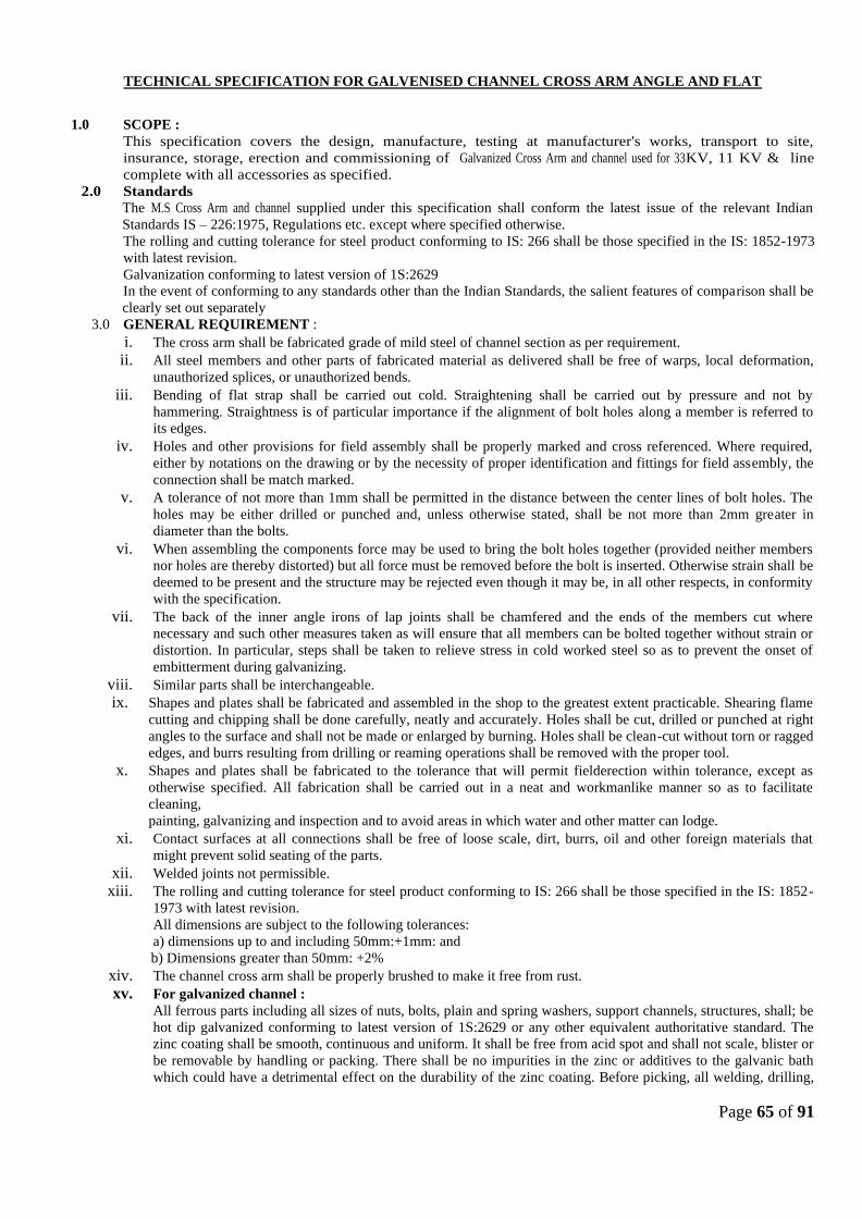
Page 65 of 91
TECHNICAL SPECIFICATION FOR GALVENISED CHANNEL CROSS ARM ANGLE AND FLAT
1.0 SCOPE :
This specification covers the design, manufacture, testing at manufacturer's works, transport to site,
insurance, storage, erection and commissioning of Galvanized Cross Arm and channel used for 33KV, 11 KV & line
complete with all accessories as specified.
2.0 Standards
The M.S Cross Arm and channel supplied under this specification shall conform the latest issue of the relevant Indian
Standards IS – 226:1975, Regulations etc. except where specified otherwise.
The rolling and cutting tolerance for steel product conforming to IS: 266 shall be those specified in the IS: 1852-1973
with latest revision.
Galvanization conforming to latest version of 1S:2629
In the event of conforming to any standards other than the Indian Standards, the salient features of comparison shall be
clearly set out separately
3.0 GENERAL REQUIREMENT :
i. The cross arm shall be fabricated grade of mild steel of channel section as per requirement.
ii. All steel members and other parts of fabricated material as delivered shall be free of warps, local deformation,
unauthorized splices, or unauthorized bends.
iii. Bending of flat strap shall be carried out cold. Straightening shall be carried out by pressure and not by
hammering. Straightness is of particular importance if the alignment of bolt holes along a member is referred to
its edges.
iv. Holes and other provisions for field assembly shall be properly marked and cross referenced. Where required,
either by notations on the drawing or by the necessity of proper identification and fittings for field assembly, the
connection shall be match marked.
v. A tolerance of not more than 1mm shall be permitted in the distance between the center lines of bolt holes. The
holes may be either drilled or punched and, unless otherwise stated, shall be not more than 2mm greater in
diameter than the bolts.
vi. When assembling the components force may be used to bring the bolt holes together (provided neither members
nor holes are thereby distorted) but all force must be removed before the bolt is inserted. Otherwise strain shall be
deemed to be present and the structure may be rejected even though it may be, in all other respects, in conformity
with the specification.
vii. The back of the inner angle irons of lap joints shall be chamfered and the ends of the members cut where
necessary and such other measures taken as will ensure that all members can be bolted together without strain or
distortion. In particular, steps shall be taken to relieve stress in cold worked steel so as to prevent the onset of
embitterment during galvanizing.
viii. Similar parts shall be interchangeable.
ix. Shapes and plates shall be fabricated and assembled in the shop to the greatest extent practicable. Shearing flame
cutting and chipping shall be done carefully, neatly and accurately. Holes shall be cut, drilled or punched at right
angles to the surface and shall not be made or enlarged by burning. Holes shall be clean-cut without torn or ragged
edges, and burrs resulting from drilling or reaming operations shall be removed with the proper tool.
x. Shapes and plates shall be fabricated to the tolerance that will permit fielderection within tolerance, except as
otherwise specified. All fabrication shall be carried out in a neat and workmanlike manner so as to facilitate
cleaning,
painting, galvanizing and inspection and to avoid areas in which water and other matter can lodge.
xi. Contact surfaces at all connections shall be free of loose scale, dirt, burrs, oil and other foreign materials that
might prevent solid seating of the parts.
xii. Welded joints not permissible.
xiii. The rolling and cutting tolerance for steel product conforming to IS: 266 shall be those specified in the IS: 1852-
1973 with latest revision.
All dimensions are subject to the following tolerances:
a) dimensions up to and including 50mm:+1mm: and
b) Dimensions greater than 50mm: +2%
xiv. The channel cross arm shall be properly brushed to make it free from rust.
xv. For galvanized channel :
All ferrous parts including all sizes of nuts, bolts, plain and spring washers, support channels, structures, shall; be
hot dip galvanized conforming to latest version of 1S:2629 or any other equivalent authoritative standard. The
zinc coating shall be smooth, continuous and uniform. It shall be free from acid spot and shall not scale, blister or
be removable by handling or packing. There shall be no impurities in the zinc or additives to the galvanic bath
which could have a detrimental effect on the durability of the zinc coating. Before picking, all welding, drilling,
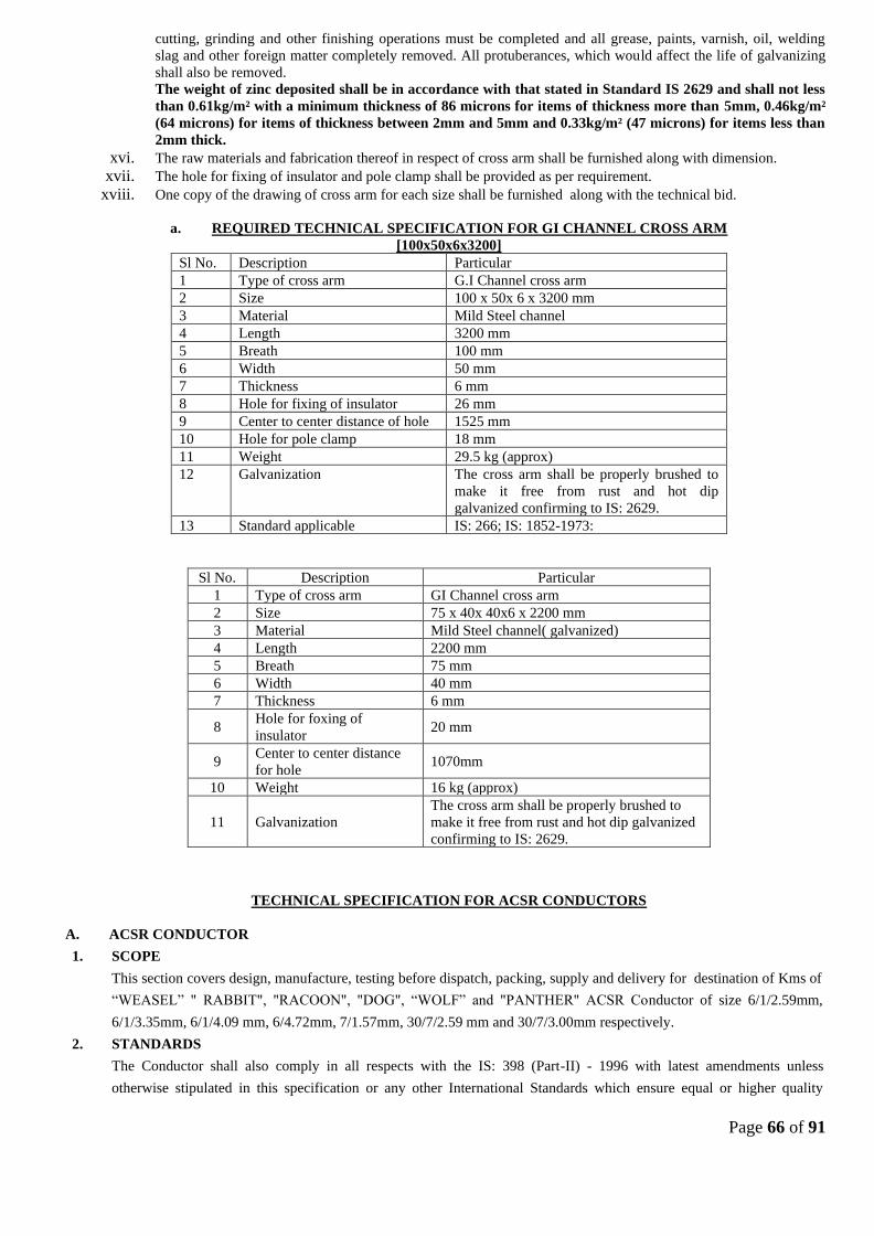
Page 66 of 91
cutting, grinding and other finishing operations must be completed and all grease, paints, varnish, oil, welding
slag and other foreign matter completely removed. All protuberances, which would affect the life of galvanizing
shall also be removed.
The weight of zinc deposited shall be in accordance with that stated in Standard IS 2629 and shall not less
than 0.61kg/m² with a minimum thickness of 86 microns for items of thickness more than 5mm, 0.46kg/m²
(64 microns) for items of thickness between 2mm and 5mm and 0.33kg/m² (47 microns) for items less than
2mm thick.
xvi. The raw materials and fabrication thereof in respect of cross arm shall be furnished along with dimension.
xvii. The hole for fixing of insulator and pole clamp shall be provided as per requirement.
xviii. One copy of the drawing of cross arm for each size shall be furnished along with the technical bid.
a. REQUIRED TECHNICAL SPECIFICATION FOR GI CHANNEL CROSS ARM
[100x50x6x3200]
Sl No. Description Particular
1 Type of cross arm G.I Channel cross arm
2 Size 100 x 50x 6 x 3200 mm
3 Material Mild Steel channel
4 Length 3200 mm
5 Breath 100 mm
6 Width 50 mm
7 Thickness 6 mm
8 Hole for fixing of insulator 26 mm
9 Center to center distance of hole 1525 mm
10 Hole for pole clamp 18 mm
11 Weight 29.5 kg (approx)
12 Galvanization The cross arm shall be properly brushed to
make it free from rust and hot dip
galvanized confirming to IS: 2629.
13 Standard applicable IS: 266; IS: 1852-1973:
Sl No. Description Particular
1 Type of cross arm GI Channel cross arm
2 Size 75 x 40x 40x6 x 2200 mm
3 Material Mild Steel channel( galvanized)
4 Length 2200 mm
5 Breath 75 mm
6 Width 40 mm
7 Thickness 6 mm
8 Hole for foxing of
insulator 20 mm
9 Center to center distance
for hole 1070mm
10 Weight 16 kg (approx)
11 Galvanization
The cross arm shall be properly brushed to
make it free from rust and hot dip galvanized
confirming to IS: 2629.
TECHNICAL SPECIFICATION FOR ACSR CONDUCTORS
A. ACSR CONDUCTOR
1. SCOPE
This section covers design, manufacture, testing before dispatch, packing, supply and delivery for destination of Kms of
“WEASEL” " RABBIT", "RACOON", "DOG", “WOLF” and "PANTHER" ACSR Conductor of size 6/1/2.59mm,
6/1/3.35mm, 6/1/4.09 mm, 6/4.72mm, 7/1.57mm, 30/7/2.59 mm and 30/7/3.00mm respectively.
2. STANDARDS
The Conductor shall also comply in all respects with the IS: 398 (Part-II) - 1996 with latest amendments unless
otherwise stipulated in this specification or any other International Standards which ensure equal or higher quality

Page 67 of 91
material.
The
ACS
R
Cond
uctor
shall
also
confor
m to the following standards: Offer Conforming to standards other than IS-398 shall be accompanied by the English
version of relevant standards in support of the guaranteed technical particulars to be furnished as per format enclosed.
3. GENERAL TECHNICAL REQUIREMENTS
The General Technical Requirements are given in Section-II. The Conductor shall conform to these technical
requirements.
The Bidder shall furnish guaranteed technical particulars in Section-III.
3.1. MATERIALS/WORKMANSHIP
3.1.1. The material offered shall be of best quality and workmanship. The steel cored Aluminum conductor strands shall
consist of hard drawn Aluminum wire manufactured from not less than 99.5% pure electrolytic Aluminum rods of E.C.
grade and copper content not exceeding 0.04%. They shall have the same properties and characteristics as prescribed
in IEC: 889-1987. The steel wire shall be made from material produced either by the acid or basic open hearth process
or by electric furnace process or basic oxygen process. Steel wire drawn from Bessemer process shall not be used.
3.1.2. The steel wires shall be evenly and uniformly coated with electrolytic high grade, 99.95% purity zinc complying with
the latest issue of IS-209 for zinc. The uniformity of zinc coating and the weight of coating shall be in accordance with
Section-II and shall be tested and determined according to the latest IS-2633 or any other authoritative standard.
3.1.3. The steel strands shall be hot dip galvanized and shall have a minimum zinc coating of 250 gm/sq.m after stranding.
The coating shall be smooth, continuous, and of uniform thickness, free from imperfections and shall withstand
minimum three dips after stranding in standard preece test. The steel strands shall be preformed and post-formed in
order to prevent spreading of strands in the event of cutting of composite core wire. The properties and characteristics
of finished strands and individual wires shall be as prescribed in IEC: 888-1987.
4. CONDUCTOR PARAMETERS
The Parameters of individual strands and composite steel cored aluminium conductor, shall be in accordance with the
values given in Section-II.
Creep in a conductor is attributed partly due to settlement of strands and partly due to non-elastic elongation of metal
when subjected to load. The manufacturer of conductor shall furnish the amount of creep which will take place in 10,
20, 30, 40 and 50 years along with the supporting calculations. The calculations shall be based on everyday
Sl.
No.
Indian
Standards Title International
1 IS:209-1979 Specification for Zinc BS-3436-1961
2 IS:398-1996 Specification for Aluminum conductors for overhead
transmission purposes.
Part-II Aluminum conductors IEC-209-1966
Galvanized steel reinforced BS-215(Part-II)
3 IS:1521-1972 Method of Tensile Testing of Steel wire ISO/R89-1959
4 IS:1778-1980 Reels and Drums for Bare conductors BS-1559-1949
5 IS:1841-1978 E.C. Grade Aluminum rod produced by rolling
6 IS:2629-1966 Recommended practice for Hot Dip Galvanizing of iron
and steel
7 IS:2633-1986 Method of testing uniformity of coating of zinc coated
articles.
8 IS:4826-1968 Galvanized coatings on round steel wires. ASTM A472-729
9 IS:5484-1978 E.C. Grade Aluminum rod produced by continuous
casting and rolling.
10 IS:6745-1972 Methods of determination of weight of zinc-coating of
zinc coated iron and steel articles
BS-443-1969

Page 68 of 91
temperature of 32 ºC and everyday tension of 25% of UTS of conductor of 11/33 KV Lines.
5. TOLERANCES
The tolerances on standard diameter of Aluminium and Steel wires shall be as detailed in specific technical
requirements.
The cross-section of any wire shall not depart from circularity by more than an amount corresponding to the tolerance
on the standard diameter.
The details of diameters, lay ratios of Aluminium and steel wires shall be in accordance with the Section-II
"Technical Requirements".
6. SURFACE CONDITIONS
All Aluminum and steel strands shall be smooth, and free from all imperfections, spills/and splits. The finished
conductor shall be smooth, compact, uniform and free from all imperfections including spills and splits, die marks,
scratches, abrasions, scuff marks, kinks (protrusion of wires), dents, pressmarks, cut marks, wire cross-over, over-
riding looseness, pressure and/or unusual bangle noise on tapping, material inclusions, white rust, powder formation
or black spots (on account of reaction with trapped rain water etc.,), dirt, grit, etc. The surface of conductor shall be
free from points, sharp edges, abrasions or other departures from smoothness or uniformity of surface contour that
would increase radio interference and corona losses. When subjected to tension upto 50% of the ultimate strength of
the conductor, the surface shall not depart from the cylindrical form nor any part of the component parts or strands
move relative to each other in such a way as to get out of place and disturb the longitudinal smoothness of the
conductor.
7. JOINTS IN WIRES
7.1. Aluminum wires
During stranding, no Aluminum wire welds shall be made for the purpose of achieving the required conductor length.
No joint shall be permitted in the individual Aluminum wires in the outer most layer of the finished Conductor.
However, joints in the 12 wire & 18 wire inner layer of the conductor are permitted but these joints shall be made by
the cold pressure butt welding and shall be such that no two such joints shall be within 15 meters of each other in the
complete stranded conductor.
7.2. Steel wires
There shall be no joints in finished steel wires forming the core of the steel reinforced Aluminium conductor.
8. STRANDING
The wires used in construction of the stranded conductor, shall, before stranding, satisfy all requirements of IS-398
(Part-II) 1996.
In all constructions, the successive layers shall be stranded in opposite directions. The wires in each layer shall be
evenly and closely stranded round the underlying wire or wires. The outer most layer of wires shall have a right hand
lay. The lay ratio of the different layers shall be within the limits given under Section-II.
9. PACKING
9.1. The conductor shall be supplied in non-returnable strong wooden drums provided with lagging of adequate strength
constructed to protect the conductor against any damage and displacement during transit, storage and subsequent
handling and stringing operations in the field. The drums shall generally conform to IS-1778-1980 and latest version
except as otherwise specified hereinafter. The conductor drums shall be adequate to wind one standard length of 2500
meters of WEASEL/RABIT/RACOON/DOG/PANTHERACSR conductor.
9.2. The drums shall be suitable for wheel mounting and for letting off the conductor under a minimum controlled tension
of the order of 5KN. The conductor drums shall be provided with necessary clamping arrangements so as to be suitable
for tension stringing of power conductor.
9.3. The bidders shall submit their drawings of the conductor drums along with the bid. After placement of letter of intent
the Manufacturer shall submit four copies of fully dimensioned drawing of the drum for Employer's approval. After
getting approval from the Employer, Manufacturer shall submit 30 more copies of the approved drawings for further
distribution and field use.
9.4. All wooden components shall be manufactured out of seasoned soft wood free from defects that may materially

Page 69 of 91
weaken the component parts of the drums. Preservative treatment for anti-termite/anti fungus shall be applied to the
entire drum with preservatives of a quality which is not harmful to the conductor.
9.5. All flanges shall be 2-ply construction with 64 mm thickness. Each ply shall be nailed and clenched together at
approximately 90 degrees. Nails shall be driven from the inside face of the flange, punched and then clenched on the
outer face. Flange boards shall not be less than the nominal thickness by more than 2 mm. There shall not be less than
2 nails per board in each circle.
9.6. The wooden battens used for making the barrel of the conductor shall be of segmental type. These shall be nailed to
the barrel supports with at least two nails. The battens shall be closely butted and shall provide a round barrel with
smooth external surface. The edges of the battens shall be rounded or chamfered to avoid damage to the conductor.
9.7. Barrel studs shall be used for construction of drums. The flanges shall be holed and the barrel supports slotted to
receive them. The barrel studs shall be threaded over a length on either end, sufficient to accommodate washers,
spindle plates and nuts for fixing flanges at the required spacing.
9.8. Normally, the nuts on the studs shall stand protruded of the flanges. All the nails used on the inner surface of the
flanges and the drum barrel shall be countersunk. The ends of the barrel shall generally be flushed with the top of the
nuts.
9.9. The inner cheek of the flanges and drum barrel surface shall be painted with bitumen based paint.
9.10. Before reeling, card board or double corrugated or thick bituminized waterproof bamboo paper shall be secured to the
drum barrel and inside of flanges of the drum by means of a suitable commercial adhesive material. The paper shall be
dried before use. Medium grade craft paper shall be used in between the layers of the conductor. After reeling the
conductor the exposed surface of the outer layer of conductor shall be wrapped with thin polythene sheet across the
flanges to preserve the conductor from dirt, grit and damage during transportation and handling and also to prevent
ingress of rain water during storage/transport.
9.11. A minimum space of 75 mm shall be provided between the inner surface of the external protective lagging and outer
layer of the conductor. Outside the protective lagging, there shall be minimum of two binders consisting of hoop
iron/galvanised steel wire. Each protective lagging shall have two recesses to accommodate the binders.
9.12. Each batten shall be securely nailed across grains as far as possible to the flange edges with at least 2 nails per end.
The length of the nails shall not be less than twice the thickness of the battens. The nail shall not protrude above the
general surface and shall not have exposed sharp edges or allow the battens to be released due to corrosion.
9.13. The conductor ends shall be properly sealed and secured with the help of U-nails on one side of the flanges.
9.14. Only one standard length of conductor shall be wound on each drum. The method of lagging to be employed shall be
clearly stated in the tender.
9.15. As an alternative to wooden drum Bidder may also supply the conductors in non-returnable painted steel drums. The
painting shall conform to IS:9954-1981,reaffirmed in 1992. Wooden/ steel drum will be treated at par for evaluation
purpose and accordingly the Bidder shall quote the package.
10. LABELLING AND MARKING
The drum number shall be branded or gauged or stencilled into the flange. An arrow shall be marked on the sides of
the drum, together with the words "Roll this way". Each drum shall have the following information provided on the
outside of the flange stencilled with indelible ink.
i) Manufacturer's name and address.
ii) Contract/Specification number.
iii) Size and type of conductor.
iv) Net weight of the conductor.
v) Gross weight of the conductor and drum.
vi) Length of the conductor.
vii) Position of the conductor end.
viii) Drum and lot number.
ix) Name and address of the consignee.
x) Month and year of manufacture.

Page 70 of 91
xi) The drum may also be marked with standard specification as per which the conductor is manufactured.
11. STANDARD LENGTHS
11.1. The standard length of the conductor shall be 2500 metres. Bidder shall indicate the standard length of the conductor to
be offered by them. A tolerance of plus or minus 5% on the standard length offered by the bidder shall be permitted.
All lengths outside this limit of tolerance shall be treated as random lengths.
11.2. Random lengths will be accepted provided no length is less than 70% of the standard length and total quantity of such
random length shall not be more than 10% of the total quantity order. When one number random length has been
manufactured at any time, five (5) more individual lengths, each equivalent to the above random length with a
tolerance of +/-5% shall also be manufactured and all above six random lengths shall be dispatched in the same
shipment. At any point, the cumulative quantity supplied including such random lengths shall not be more than 12.5%
of the total cumulative quantity supplied including such random lengths. However, the last 20% of the quantity ordered
shall be supplied only in standard length as specified.
11.3. Bidder shall also indicate the maximum single length, above the standard length, he can manufacture in the guaranteed
technical particulars of offer. This is required for special stretches like river crossing etc. The Employer reserves the
right to place orders for the above lengths on the same terms and conditions applicable for the standard lengths during
the pendency of the Contract.
12. QUALITY ASSURANCE PLAN
A Quality Assurance Plan including customer hold points covering the manufacturing activities of the material shall
be required to be submitted by the tenderer to the Employer along with the tender. The Quality Assurance Plan
after the same is found acceptable, will be approved by the Employer.
The contractor shall follow the approved Quality Assurance Plan in true spirit. If desired by the Employer, he shall
give access to all the documents and materials to satisfy the Employer that the Quality Assurance Plan is being
properly followed.

Page 71 of 91
SECTION - II
SPECIFIC TECHNICAL REQUIREMENTS
1. SCOPE
This section of the specification covers climatic and isoceraunic conditions, specific technical particulars, schedule of
requirements & desired deliveries, for conductor for 11/33 kV lines.
2. CLIMATIC & ISOCERAUNIC CONDITIONS:
CONDUCTOR
1. Conductor: Raccoon ACSR
2. IS applicable: IS-398 (part-II) 1996 latest revision
3. Wire Diameter Raccoon
Aluminium (mm) 6/4.09
Steel(mm) 1/4.09
4. Number of strands:
Steel centre 1
1st steel layer
1st Aluminium layer 6
2nd Aluminium layer
5. Sectional Area of Aluminium (sq. mm.) 78.83
6. Total Sectional Area(sq.mm.) 91.97
7. Overall diameter(mm) 12.27
8. Approximate weight(Kg./Km.) 319
9. Calculated D.C rersistance at 20 degrees C.,
maximum. (Ohms/Km)
0.371
10. Ultimate tensile strength (KN) 26.91
11. Final modulas of elasticity (GN/sq.m) 79
12. Coefficient of linear expansion x 10-6 per◦C 19.1
13. Lay ratio Max /Min
Steel core 6 wire layer
Aluminium Ist layer 14
10
2nd layer
14. Technical Particulars
a. Diameter-mm Al Steel
Standard(mm) 4.09 4.09
2.1 Maximum Temperature
a) Conductor ºC.
2.2Minimum Temperature ºC.
2.3 i)Max. ambient temperature ºC
ii) Mean annual / every day temperature ºC
2.4Basic wind speed m/s
2.5Relative humidity
i) i) Maximum %
ii) Minimum %
2.6Average Rainfall (Max.) mm per annum
2.7a)Rainy months May to Sept.
15 Rainy days in a year (days)

Page 72 of 91
Maximum (mm) 4.17 4.17
Minimum (mm) 4.01 4.01
b. Cross-sectional area of nominal diameter wire
(mm2)
13.14 13.14
c. Weight (Kg./Km) 102.48 35.51
d. Min. breaking load (KN)
Before stranding 17.27 2.08
After Stranding 16.4 1.98
e. D.C resistance at 20̊C min. (Ohm/Km) 0.371
15. Zinc coating of steel core:
(i) Number of 1 minute dips: 3
(ii) Minimum weight of Zinc: 260 gms/sqm Coating
(iii) Process of Galvanizing: Hot dip.
(iv) Quality of Zinc: IS-209/1979 or latest edition.
16. Joints in strands
16.1 Steel : Not permitted
16.2 Aluminium: No joint shall be permitted in the Aluminium wires in the outer most layer of the ACSR conductor. But
permitted in the inner layers such that no two such joints are within 15 meters of each other in the complete stranded
conductor.
17 Chemical composition of high carbon steel wire:
TECHNICAL SPECIFICATION FOR COMPOSITE POLYMERIC INSULATORS FOR USE IN
11KV AND 33 KV SYSTEM
SCOPE
This section covers the specifications for design, manufacture, shop & laboratory testing, supply before
dispatch & supply of Composite polymeric insulator consisting of a load bearing cylindrical insulating solid
core consisting of fibres usually glass in a resin based matrix, a housing (outside the insulating core) made
of polymeric material and end fittings permanently attached to the insulating core for a.c system with a
nominal voltage greater than 1000 V for overhead lines.
The Composite insulator shall be pin insulator for straight line location and Long rod insulator for
conductors in tension application at angle/ cut point. The composite tension / suspension insulator shall be
of suitable for boll and socket type or tongue & Clevis type fittings.
1. APPLICABLE STANDARD: Following international standard are applicable for composite polymeric
insulation with latest amendment and other relevant national & internal standard also been application with
latest amendment.
The composite insulators including the end fitting connection shall be of standard design suitable for use
with the hardware fittings of any make conforming to relevant IEC/IS standards. Sl. No.
Indian Standard Title International Standard
1. IEC
Definition, test method and acceptance criteria for composite insulators for a. c. overhead lines above. IEC:61109
Element % Composition
i) Carbon 0.5 to 0.85
ii) Manganese 0.5 to 1.10
iii) Phosphorus Not more than 0.035
iv) Sulphur Not more than 0.045
v) Silicon 0.10 to 0.35

Page 73 of 91
2. IS:731
Porcelain insulators for overhead power lines with a nominal voltage greater than 1000V IEC:60383
3. IS:2071 Methods of High voltage testing IEC:60060-1
4.
IS:2486
Specification for insulator fitting for overhead
power lines with a nominal voltage greater than
1000V General Requirements and tests Dimensional Requirements locking devices.
IEC:6012
0
IEC:6037
2
5. Thermal mechanical performances test on string insulator units. IEC:60575
6. IS:13134
Guide for the selection of insulators in respect of polluted conditions. IEC:60815
7. Characteristics of string insulator units of the long rod type. IEC:60433
8. Hydrophobicity classification STRI GUIDE 1.92/1
9. Radio interference characteristics of overhead power lines and high-voltage equipment CISPR:18-2 PART2
10. IS:8263 Methods of RI test of HV insulators IEC:60437
11. Standard for insulators- composite distribution dead end type ANSI c29.13-2000
12. IS:4759
Hot dip Zinc coatings on structural steel & other allied products.
ISO:1459 ISO:1461
13. IS:2629
Recommendation of weight for hot, dip galvanization for iron and steel ISO:1461(E)
14. IS:6745
Determination of weight of Zinc coatings on zinc coated iron and steel articles ISO:1460
15. IS:3203
Method of testing of local thickness of electroplated coating ISO:2178
16. IS:2633 Testing of uniformity of coating of zinc coated articles
17. Standard specification for glass fiber standards ASTM D 578-05
18. Standard test method for compositional analysis of thermogravimetry ASTME 1131- 03
19. IS:4699 Specification for refined secondary Zinc
2. SERVICE CONDITION
Maximum ambient temperature : *480 C
Minimum ambient temperature : - 50 C
Relative humidity : 0 to 100%
The size of composite insulator, minimum creepage distance and mechanical strength along with hardware
fittings shall be as follows.
3. TERMS AND DEFINITION:
I. The polymeric insulator whose insulating body consists of organic base materials also known as
non ceramic insulator and coupling device shall be attached to the end of the insulating body.
II. The composite polymeric insulator shall be made two insulating part- namely a core and a housing
part. The core consisting of fibres (e.g glass) which are position in a resin based matrix or a
homogeneous insulating material (resin) III. The insulator trunk which is the central insulating part of an insulator from which the sheds project.
IV. The housing which is the external insulating part of a composite insulator providing the necessary
creapage distance and protecting core from environment.
V. The shed of the insulator which is the insulating part projecting from the insulator trunk , intended
to increase the creepage distance.
VI. The interface which is the surface between housing and fixating device, between various parts of
the housing e.g between shed or between sheath and shes, between core and housing.
VII. The end fitting which provide integral component or formed part of an insulator intended to

Page 74 of 91
connect it to a supporting structure , or to a conductor or to an item of equipment or to another
insulator.
Sl
.
N
o.
Type of
compos
ite
insulat
or
Nomi
nal
syste
m
volta
ge
KV
(rms)
Highest
system
voltage
KV
(rms)
Visible
discharg
e test
voltage
KV
(rms
Wet
power
frequen
cy
withsta
nd
voltage
KV
(rms
Impuls
e
withsta
nd
voltage
KV
(rms
Minimum
Creepage
distance (mm)
Min.
Failing
load
KN
Pin ball
shankd
iameter
mm
Normal
&
modera
tely
polluted
(20mm/
KV)
Heavily
polluted
(25mm/
KV)
i Long
rod
insulat
or
11 12 9 35 75 240 320 45 16
33 36 27 75 170 720 900 45/70**
ii Post/
pin
insula
tor
11 12 9 35 75 240 320 5
33 36 2
7
75 170 720 900 10
Dimensional Tolerance of composite insulators
±(0.04d=1.5) mm when d < 300 mm
±(0.025d=6) mm when d < 300 mm
4. Inter changeability
The composite insulators including the end fitting connection shall be of standard design suitable for use
with the hardware fittings of any make conforming to relevant IEC/IS standards.
5. Corona and RI performance
All surfaces shall be clean, smooth without cuts, abrasions or projections. No parts shall be subjected to
excessive localized pressure. The insulator and metal parts shall be so designed and manufactured that it
shall avoid local corona formation and not generate any radio interference beyond specified limit under the
operating conditions.
6. Core
It shall be a glass – fiber reinforce epoxy resin rod of high strength (FRP rod). Glass fibers and resin shall
be optimized in the FRP rod. Glass fibers shall be Boron free electrically corrosion resistant (ECR) glass
fiber or boron free E- class and shall exhibit both high electrical integrity and high resistance to acid
corrosion . the matrix of the FRP rod shall be Hydrolysis resistant. The FRP rod shall be manufactured
through pultrusion process. The FRP rod shall be void free. Housing (Sheath)
The FRP rod shall be covered by a seamless sheath of a silicon elastometric compound or silicon alloy
compound of a thickness of 3 mm minimum.
It shall protect the FRP rod against environment influences, external pollution and humidity. It shall be
excluded or directly moulded on the core and shall have chemical bonding with the FRP rod. The strength
of the bond shall be greater than the tearing strength of the polymer. Sheath material in the bulk as in the
sealing/ bonding area shall be free from voids.
7. Weather sheds
The composite polymer weather sheds made of silicon elastomeric compound of silicon alloy shall be
firmly bounded to the sheath, vulcanized to the sheath or moulded as part of the sheath and shall be free
from imperfections. The weather sheds shall have silicon content of minimum 30% by weight. The strength
of the weather sheds to sheath interface shall be greater than the tearing strength of the polymer. The
interface, if any, between sheds and sheath (housing) shall be free from voids.
8. End Fittings
End fittings transmit then mechanical load to the core. They shall be made of spheroid graphite cast iron,
malleable cast iron or forged steel or aluminium alloy. They shall be connected to the rod by means of a
controlled compression technique. The gap between fitting and sheath shall be sealed by a flexible silicon
elastomeric compound or silicon alloy compound sealant. System of attachment of end fitting to the rod

Page 75 of 91
shall provide superior sealing performance between housing, i.e. seamless sheath and metal connection. The
sealing must be moisture proof.
The dimensions of end fittings of Insulators shall be in accordance with the standard dimensions stated in
IS:2486/IEC:60120
9. Equipment Marking
I. Each insulator unit shall be legibly and marked with the following details as per IEC-61109
(a) Month & Year of manufacture
(b) Min. Failing load/ guaranteed mechanical strength in kilo Newton followed by the word KN to facilitate
easy identification.
(c) Manufacture’s name / trade mark.
II. One 10mm thick ring or 20mm thick spot of suitable quality of paint shall be marked on the end fitting of
each composite long rod of [particular strength in case of 33 KV insulators for identification in case both type
of insulators are procured by the utility. The paint shall be not have deteriorating effect on the insulator
performance, following codes shall be used as identification mark:
For 45 KN Long unit : Blue
For 70 KN Long unit : Red
10. Bid Drawings
I. The full description and illustration of the materials offered.
II. The bidder furnish alongwith the bid the outline drawing (3 copies) of each insulator unit including
a cross sectional view of the long rod insulator unit. The drawing shall include but not be limited
to the following information.
(a) Long rod diameter with manufacturing tolerance.
(b) Minimum creepage distance with positive tolerance.
(c) Protected creepage distance.
(d) Eccentricity of the long rod unit
(i) Axial run out
(ii) Radial run out
(e) Unit mechanical and electrical characteristics
(f) Size and weight of ball and socket/ tongue & cleaves
(g) Weight of composite long rod units
(h) Materials
(i) Identification Mark
(ii) Manufacturer’s catalogue number
Type tests
Sl. No. Description of type test Test procedure / standard
1. Dry lightning impulse withstand voltage test
As per IEC 61109 (Clause 6.1)
2. Wet power frequency test As per IEC 61109 (Clause 6.2) 3. Mechanical load- time test As per IEC 61109 (Clause 6.4) 4. Radio Interference test As per IEC 61109 (Clause 6.5) revised
5. Recovery of Hydrophobicity test Annexure-B This test may be repeated every 3 yrs by the manufacturer
6. Chemical composition test for silicon content
Annexure-B or any other test method acceptable to the owner
7. Brittle fracture resistance test Annexure-B
11. Acceptance (Sample) Tests
A. For Composite Insulators
A Verification of dimensions Clause 7.2 IEC:61109
B Verification of the locking system ( if possible) Clause 7.3 IEC:61109
C Galvanizing Test IS 2633 / IS 6745
D Verification of the specified mechanical load Clause 7.4 IEC:61109
B. Routine Tests
Sl. No. Description Standard
1. Identification of marking As per IEC:61109 Clause 8.1

Page 76 of 91
2. Visual Inspection As per IEC:61109 Clause 8.2
3. Mechanical routine test As per IEC:61109 Clause 8.3
C. Tests During Manufacture
Following tests shall also be carried our
A Chemical analysis of zinc used for galvanizing
B Chemical analysis, mechanical, metallographic test and magnetic particle inspection for
malleable castings
C Chemical analysis, hardness and magnetic particle inspection for forigngs

Page 77 of 91
TECHNICAL SPECIFICATION FOR G.I. WIRE
1.0 Scope This specification covers the manufacturing, testing at works, transport to site, insurance, storage,
erection and commissioning of Galvanised Iron Wire of sizes 4 mm and 5 mm diameter.
2.0 General requirements It relating to the supply of mild steel wire shall be as per IS: 1387/1967 and the wire shall be
drawn from the wire rods conforming to IS: 7887/1975.
The requirements for chemical composition for the wires shall conform to IS:7887/1975. Mild steel wire for General
Engineering purpose shall be of following sizes:
I) 4mm - diameter (8 SWG)
II) 5mm - diameter (6 SWG)
Tolerance permitted on the diameter of wire shall be as per Table -1 of IS:280/1978.
3.0 Climatic Conditions The cross arms shall be suitable for the climatic condition mentioned In these
bidding documents:
Mechanical Properties
Tensile Test: Tensile strength of wire when tested in accordance with IS: 1521-1972, shall be within the
limits given in Table-2 of IS: 280/1978.
Wrapping Test: Wires shall be subjected wrapping test in accordance with IS: 1755-1961. The wire shall
withstand without breaking or splitting. being wrapped eight times round its own diameter and
subsequently straightened.
Surface finish
a. The wire shall have galvanized finishes. The galvanized coating of steel wire shall conform to the
requirements for anyone of the types of coatings given in IS: 4826-1968 as per agreement with the
purchaser.
b. The coating test for finishes other than galvanized, copper coated or tinned shall be subject to between the
purchaser and the manufacturer.
c. Unless otherwise agreed to the method of drawing representative samples of the material and the criteria
for conforming shall be as prescribed in Appendix (A) of IS: 280/1978.
d. All finished wires shall be well and cleanly drawn to the dimensions specified. The wire shall be sound,
free from splits, surface flaws, rough jagged and imperfect edges and other harmful surface defects.
e. Each coil of wire shall be suitably bound and fastened compactly and shall be protected by suitably
wrapped.
4.0 Marking Each coil of wire shall be marked legibly with the finish size of wire, lot number and trade mark
of the name of the manufacturer. The material may also be marked with the ISI certification mark and
name of the project.
5.0 INSPECTION: Inspection may be carried out by the purchaser or third party nominee at any stage of
manufacture. The supplier shall grant free access to the purchaser's representative or third party nominee
at a reasonable time when the work is in progress. Inspection and acceptance of any equipment under this
specification by the purchaser shall not relieve the supplier of his obligation of furnishing equipment in
accordance with the specification and shall not prevent subsequent rejection if the equipment is found
defective.
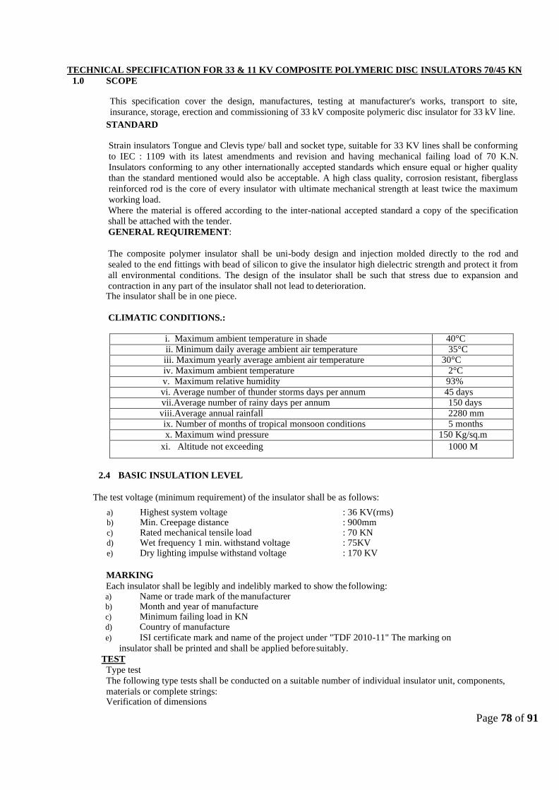
Page 78 of 91
TECHNICAL SPECIFICATION FOR 33 & 11 KV COMPOSITE POLYMERIC DISC INSULATORS 70/45 KN
1.0 SCOPE
This specification cover the design, manufactures, testing at manufacturer's works, transport to site,
insurance, storage, erection and commissioning of 33 kV composite polymeric disc insulator for 33 kV line.
STANDARD
Strain insulators Tongue and Clevis type/ ball and socket type, suitable for 33 KV lines shall be conforming
to IEC : 1109 with its latest amendments and revision and having mechanical failing load of 70 K.N.
Insulators conforming to any other internationally accepted standards which ensure equal or higher quality
than the standard mentioned would also be acceptable. A high class quality, corrosion resistant, fiberglass
reinforced rod is the core of every insulator with ultimate mechanical strength at least twice the maximum
working load.
Where the material is offered according to the inter-national accepted standard a copy of the specification
shall be attached with the tender.
GENERAL REQUIREMENT:
The composite polymer insulator shall be uni-body design and injection molded directly to the rod and
sealed to the end fittings with bead of silicon to give the insulator high dielectric strength and protect it from
all environmental conditions. The design of the insulator shall be such that stress due to expansion and
contraction in any part of the insulator shall not lead to deterioration. The insulator shall be in one piece.
CLIMATIC CONDITIONS.:
i. Maximum ambient temperature in shade 40°C
ii. Minimum daily average ambient air temperature 35°C iii. Maximum yearly average ambient air temperature 30°C
iv. Maximum ambient temperature 2°C
v. Maximum relative humidity 93%
vi. Average number of thunder storms days per annum 45 days vii.Average number of rainy days per annum 150 days
viii.Average annual rainfall 2280 mm ix. Number of months of tropical monsoon conditions 5 months
x. Maximum wind pressure 150 Kg/sq.m
xi. Altitude not exceeding 1000 M
2.4 BASIC INSULATION LEVEL
The test voltage (minimum requirement) of the insulator shall be as follows:
a) Highest system voltage : 36 KV(rms) b) Min. Creepage distance : 900mm c) Rated mechanical tensile load : 70 KN d) Wet frequency 1 min. withstand voltage : 75KV e) Dry lighting impulse withstand voltage : 170 KV
MARKING
Each insulator shall be legibly and indelibly marked to show the following: a) Name or trade mark of the manufacturer b) Month and year of manufacture c) Minimum failing load in KN d) Country of manufacture
e) ISI certificate mark and name of the project under "TDF 2010-11" The marking on
insulator shall be printed and shall be applied before suitably.
TEST
Type test
The following type tests shall be conducted on a suitable number of individual insulator unit, components,
materials or complete strings: Verification of dimensions

Page 79 of 91
Thermal mechanical performance test Power frequency voltage withstand and flashover test (i) dry (ii) wet Impulse voltage withstand and flashover test (dry) Visible discharge test (dry) RIV test (dry) Mechanical failing Load Test (for pin insulator only) 24 hrs. mechanical strength test (for strain I string insulator only)
Acceptance Tests a) Visual examination b) Verification of dimensions c) Temperature cycle test d) Galvanizing test
e) Mechanical performance test f) Test on locking device for ball and socket coupling g) Eccentricity test h) Metallurgical test i) Grain size j) Inclusion rating k) Chemical analysis l) Microstructure m) Mechanical failing load test (for Pin Insulator only) n) Electro-mechanical strength test (for Strain insulator only) o) Porosity test
p) Puncture test (for strain Insulator only)
Routine Tests
a. Visual Inspection b. Mechanical routine test for Strain Insulator only) c. Electrical routine test (for Strain Insulator only)
Tests During Manufacture
On all components as applicable a) Chemical analysis of zinc used for galvanizing b) Chemical analysis, mechanical, metallographic test and magnetic particle inspection for malleable castings. c) Chemical analysis hardness tests and magnetic particle inspection for forgings d) Hydraulic Internal Pressure tests On disc insulator shells
Test Reports
Copies of type test reports shall be furnished in at least six (6)' copies along with one original. One copy shall
be returned duly certified by the Owner only after which the commercial production of the concerned
materials shall start.
Copies of acceptance test reports shall be furnished in at least six (6) copies. One copy shall be returned duly
certified by the Owner, only after which the material shall be despatch.
Record of routine test reports shall be maintained by the Contractor at his works for periodic inspection by
the Owner's representative.
Test certificates of test during manufacture shall be maintained by the Contractor. These shall be produced
for verification as and 'When desired by the Owner.
INSPECTION
The Owner's representative or third party nominee shall at all times be entitled to have access to the works
and all places of manufacture, where insulator, and its component parts shall be manufactured and the
representatives shall have full facilities for unrestricted inspection of the Contractor's and sub Contractor's
works, raw materials, manufacture of the material and for conducting necessary test as detailed herein.
The material for final inspection shall be offered by the Contractor only under packed condition as detailed in
the specification. The Owner shall select samples at random from the packed lot for carrying out
acceptance

Page 80 of 91
After placement of award, the Contractor shall submit fully dimensioned insulator drawings containing all the
details, in four (4) copies to Owner for approval. After getting approval from Owner and successful completion of
all the type tests, the Contractor shall submit 20 more copies of the same drawing to the Owner for further
distribution and field use at Owner's end.
TECHNICAL SPECIFICATION FOR XLPE POWER CABLES (11KV &33 KV)
SECTION I
STANDARD TECHNICAL REQUIREMENT
1.0 SCOPE:
T his sect ion covers t he st andard technical requirement s of design, manufact uring, test ing, packing and dispat
ching of 11 kV and 33 kV XLPE HT Pow er Cable.
2.0 APPLICABLE STANDARDS
T he mat erials shall conform t o t he lat est edit ions of t he follow ing Indian/Int ernat ional St andards :
IS 7098 Part 2 : 1985 XLPE insulat ed PVC sheat hed cables For w orking volt ages from 3.3 kV
up t o and including 33 kV IS 5831 : 1984 PVC Insulat ion and Sheat h of elect ric Cables
IS 8130:1984 Conductors for insulat ed elect ric cables and flexible cords. IS 613:1984 Copper rods and bars
for elect rical purposes. IS 3975:1988 Mild st eel w ires, formed and t apes for armouring of cable. IS 10810:1984 Met hod of t est s for cables. IEEE-383:1974 St andard for t ype test of class IE elect ric cables, field splices, and connections for nuclear pow er generat ing st at ions. AST M-D2843,1993 Standard t est method for densit y of smoke from burning or decomposit ion
of plast ics. AST M-D2863, 1991 St andard t est met hod for measuring minimum oxygen concent rat ion t o support candle - like combust ion of plast ics (oxygen index).
NEMA-W C5,1992 T hermoplast ic Insulat e d W ire and cable for t he t ransmission and dist ribut ion of
Elect rical Energy. IEC:754 T est on gases evolved during combust ion of elect ric cables -
(Part -1):1994 Determinat ion of t he amount of halogen acid gas evolved during combust ion of polymeric mat erials t
aken from cables. IEC:332 T est on elect ric cables under fire condit ions (Part I):1993 T est on a single vert ical insulat ed w ire or cable. IS 3961 Recommended current rat ing for
cables - (Part II):1967 PVC insulat ed and PVC sheat hed heavy dut y cables. IS 10418:1982

Page 81 of 91
Drums for elect ric cables.
3.0 GENERAL REQUIREMENTS
All cables shall be suit able for high ambient , high humid t ropical Indian Climat ic condit ions. Cables shall be
designed t o withstand t he mechanical, electrical and t hermal st resses under t he unforeseen st eady st at e
and t ransient condit ions and shall be suit able for proposed met hod of inst allat ion.
Conduct or shall be of uniform, of good qualit y, free from defect s Aluminium copper. Insulat ion shall
be Cross Linked Polyet hylene (XLPE).
For 33 kV and 11 kV cables, conduct or screen and insulat ion screen shall bot h be ext ruded,
semi-conducting compound and shall be applied along -w it h XLPE insulat ion in a single operat ion by t riple ext rusion process. Met hod of curing for 33 kV cable shall be "Dry curing/ gas curing " only, w hereas for 11 kV and 3.3 kV cables it shall be "Dry curing/ gas curing / St eam curing".
Ext ruded Semi-conducting screening and met allic screening of copper t ape shall be generally as per IS 7098
(Part -II) w it h lat est amendment s. T he semi conduct ing compound shall be suit able for t he operat ing t
emperat ure of t he cable and compat ible w it h t he insulat ing mat erial. T he insulat ion screen shall be an ext ruded layer of black semi-conduct ing compound and cont inuously
covers t he w hole area of insu lat ion. T he semi-conduct ing screens should be effect ively cross linked t o
achieve 90 ᵒ C cable rat ing. T he contact surface between insulat ion and insulat ion screen shall be smoot h
and free from prot rusion and irregularit ies. T he int erface bet w een insulat ion and insulat ion screen shall be free of any voids. Insulat ion screen shall be st rippable t ype. T he met allic screen shall consist of a layer of copper cable applied in helical form. Inner sheat h - All armoured and mult i-core un-armoured cables shall have dist inct ext ruded inner PVC sheat h of black colour. Armouring - Mat erial for armour for Single Core Cable shall be Aluminum w ire. For Mult icore cable it shall be GS w ire / flat . Armouring shall be as per relevant IS and it shall have minimum 90% coverage.
Breaking Load of t he joint s shall be minimum 95% of t he normal armour.
Out er Sheat h – It shall be of black colour PVC (t ype ST 2 as per IS 5831) w it h Cable size and Volt age grade embossed on it . Sequential marking shall be at every 1 (one ) Met er dist ance. W ord "FRLS" shall also be
embossed on it at every 5 ( Five ) met er dist ance. FRLS Propert ies - All cable shall be Flame Ret ardant , Low Smoke (FRLS) t ype. Out er sheat h shall have t he follow ing propert ies –
Acid Gas Generat ion – Max 20% ( as per IEC 754-1) Smoke densit y rat
ing: 60% (As per AST MD 2843)
Flammabilit y t est - As per Sw edish chimney t est F3 as per SEN 4241475 As per IEC 332 part -3 (Cat egory B) Minimum bending radius
shall be 10 D Repaired cables shall not be accept able.
4.0 CURRENT RATING OF CABLES

Page 82 of 91
1) Normal current rat ing shall not be less t han t hat covere d by IS 3961. Vendor shall submit dat a in respect of
all cables in t he prescribed format .
2) T ables given de-rat ing fact ors for various condit ions of cable inst allat ion including t he follow ing, for all t
ypes of cables shall be furnished. - Variat ion in ambient air t emperat ure. - Variat ion in ground t emperat ure.
- Dept h of laying.
- Cables laid in t he ground - Cables laid in t rench
- Cables laid in duct s - Soil resist ivit y.
- Grouping of cables.
3) T he value of short circuit w it hst and current rat ings of all cables shall be indicat ed for a short circuit for 1
second durat ion and should also specify t he maximum t emperat ure during short circuit .
4) T he follow ing fact ors shall also be account ed for, w hile specifying t he maximum short circuit w it hst and
of t he cables.
5) Deformat ion of t he insulat ion, due t o t hermo -mechanical forces produced by t he short circuit condit ions, can reduce t he effect ive t hickness of insulat ion.
6) Conduct or and core screens can be adversely affect ed w it h loss of screening effect .
Likew ise t he t hermal propert ies of t he out er sheat h mat erial can be t he limit at ion.
7) It is essent ial t hat t he accessories w hich are used in t he cable syst em w it h mechanical and/or soldered
connect ions are suit able for t he t emperat ure adopt ed for t he cables.
8) Formula for calculat ing short circuit current for different durat ion or curve show ing short t ime current v/s t ime for different sizes of cables shall be furnished by vendor. 5.0 CABLE DRUMS
5.1 Cables shall be supplied in non-ret urnable w ooden or st eel drums of heavy c onst ruction and drum shall be
properly seasoned, sound and free from defect s. W ood preservat ive shall be applied t o t he ent ire drum.
5.2 All Pow er Cables shall be supplied in drum lengt h of 1000 m. Each drum shall cont ain one cont inuous lengt h of cable. Ow ner shall have t he opt ion of reject ing cable drums w it h short er lengt hs. T he cable length per drum is allow ed a t olerance of +5%. T he t olerance allow ed on t ot al quant it y of each size is as given below .
3.150 met ers for cable lengt h upt o 10 kms.
3.2100 met ers for cable lengt h more t han 10 kms. and up t o 20 kms. 3.3150 met ers for cable lengt h more t han 20 kms. W here t he ordered quant it y is not mult iple of 1000 m and t he increment al quant it y is very small, t he
same may be included in one of t he drums. Ot herw ise, an ad dit ional lengt h for t he increment al quant it y w ill
be supplied.
5.3 A layer of w at er proof paper shall be applied t o t he surface of t he drums and over t he outer most cable layer. 5.4 A clear space of at least 40mm shall be left bet w een t he cables and t he logging.
5.5 Each drum shall carry manufact urer’s name, purchaser’s name, address and cont ract number, it em number
and t ype, size and lengt h of t he cable, net and gross w eight st enciled on bot h sides of drum. A t ag cont aining t he same informat ion shall be at t ached t o t he leading end of t he cable. An arrow and suit able accompanying w
ordings shall be marked on one end of t he reel indicat ing t he direct ion in w hich it should be rolled.
5.6 Packing shall be st urdy and adequat e t o protect t he cables, from any injury due t o mishandling or ot her condit

Page 83 of 91
ions encountered during t ransport at ion, handling and st orage. Bot h cable ends shall be sealed w it h PVC/Rubber caps so as t o eliminat e ingress of w at er during t ransport at ion and erect ion. 6.0 TESTS
6.1 T ype T est s
T he follow ing shall const it ut e t ype t est s:
i) T est s on conduct or
a. Annealing t est (for copper)
b. T ensile t est s (for aluminium)
c. W rapping t est s (for aluminium)
d. Resist ance t est
ii) T est s for armouring w ires/st rips
iii) T est for t hickness of insulat ion and sheat h iv) Physical t
est s for insulat ion
a. T ensile st rengt h and elongat ion at break b. Ageing in air oven
c. Hot t est
d. Shrinkage t est
e. W at er absorpt ion (gravimet ric)
v) Physical t est s for out sheat h
a. T ensile st rengt h and elongat ion at break b. Ageing in air oven
c. Hot t est
d. Shrinkage t est
vi) Bleeding and blooming t est s (for out er sheat h)
vii) Part ial discharge t est viii) Bending t
est
ix) Dielect ric pow er fact or t est
a. As a funct ion of volt age
b. As a funct ion of t emperat ure
x) Insulat ion resist ance (volume recept ivit y) t est s xi) Heat ing
cycle t est
xii) Impulse w it hst and t est xiii) High volt
age t est
xiv) Flammabilit y t est
6.2 Accept ance t est s
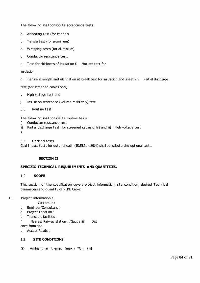
Page 84 of 91
T he follow ing shall const it ut e accept ance t est s:
a. Annealing t est (for copper) b. T ensile t est (for aluminium) c. W rapping t est s (for aluminium)
d. Conduct or resist ance t est ,
e. T est for t hickness of insulat ion f. Hot set t est for
insulat ion,
g. T ensile st rengt h and elongat ion at break t est for insulat ion and sheat h h. Part ial discharge
t est (for screened cables only)
i. High volt age t est and j. Insulat ion resist ance (volume resist ively) t est 6.3 Rout ine t est
T he follow ing shall const it ut e rout ine t est s:
i) Conduct or resist ance t est
ii) Part ial discharge t est (for screened cables only) and iii) High volt age t est
s.
6.4 Opt ional t est s
Cold impact t est s for out er sheat h (IS:5831 -1984) shall const it ut e t he opt ional t est s.
SECTION II
SPECIFIC TECHNICAL REQUIREMENTS AND QUANTITIES.
1.0 SCOPE
T his sect ion of t he specificat ion covers project informat ion, sit e condit ion, desired T echnical
paramet ers and quant it y of XLPE Cable.
1.1 Project Informat ion a.
Cust omer :
b. Engineer/Consult ant :
c. Project Locat ion :
d. T ransport facilit ies
i) Nearest Railw ay st at ion : /Gauge ii) Dist
ance from sit e :
e. Access Roads :
1.2 SITE CONDITIONS
(i) Ambient air t emp. (max.) °C : (ii)

Page 85 of 91
Ambient air t emp. (min.) °C : (iii) Design
ambient t emp. °C :
1.2.1 Relat ive humidit y for design : purposes
1.2.2 Height above mean sea level in : met ers
1.2.3 Eart h quake dat a
i) Seismic zone : IS:1893-84
ii) Seismic accelerat ion : As per IS 2.2.4
1.2.4 W ind dat a
Sit e W ind Pressure Kgf/m2 : As per IS 2.3
1.3 Syst em Part iculars
a
.
Line Volt age (kV) 11/33
b
.
Highest Syst em Volt age
(kV)
12/36
c.
Number of Circuit s 1
d.
Frequency HZ50
e
.
Neut ral effect ively eart hed
f
.
Short circuit level (KA) 22.77 KA, 31.8K A / 22.5K A, 4 5K A
1.4 SPECIFIC TECHNICAL REQUIREMNTS
T echnical Paramet ers of t he cable shall be as follow s:
S. No.
PARTICULAR Unit DATA DATA
1 Rat ed Volt age kV 6.35/1 1 19.0/3 3
2 T ype of Insulat ion - XLPE XLPE
3 Single core/ Mult i core - Single/T hree core Single/T hree core
4 Armoured / Unarmoured - Armoured Armoured
5 Mat erial of Conduct or - Aluminiu m / C op pe r Aluminiu m / C op pe r
6 Syst em - 11 kV Earthe d 33 kV Earthe d
7 Highest Syst em Volt age kV 12 36
8 Conduct or size sq. mm 120, 150, 185, 240, 300 150, 185, 240, 300, 400
9
Mat erial
Stra n de d Aluminiu m /c op
pe r
Stra n de d
Aluminiu m / co pp e r 10 Shape of Conduct or Circu la r Circu la r
11 Short Circuit Current kA 13.12 , 18.35 for 3 secs. 13.12, 26.24 for 3 secs
12
Pow er Frequency W it hst and
Volt age
KV rms
28
70
13
Light ning Impulse W it hst and
Volt age
kVp
75
170
14
Cont inuous W it hst and
T emperat ure
Deg C
90
90
15
Short Circuit w it hst and
T emperat ure
Deg C
250
250
16
Oxygen Index
Min 29 (as per ASTM D
2863)
Min 29 (as per ASTM D
2863)
17
Acid Gas Generat ion
Max 20% ( as per IEC 754 -
1)
Max 20% ( as per IEC
754-1)

Page 86 of 91
18.
Smoke Densit y Generat ion
60% (As per ASTM D
2843)
60% (As per AST MD
2843)
19.
Flammabilit y T est
As per Sw edish Chimney
t est
As per Swe dish
Chimn e y test
SECTION-III
GUARANTEED TECHNICAL PARTICULARS
Sl. No. Item Particulars Unit
1 Manufacturers Name & Address
2 Country of manufacturer
3 Type of cable
4 Applicable standards for manufacturing
5 Applicable standards for testing
6 Rated voltage kV
7 Maximum service voltage kV
8
Maximum continuous current carrying capacity per cable
when lain in air at an ambient air temperature of 50 deg.
(single core cables solid bonded)
A
9
Maximum continuous current carrying capacity per cale when
lain in ground at a depth of 1.0 m (ground temp. 40 deg. C
and soil thermal resistivity of 150 deg.c/watt/cm max.
Conductor temp. 90 deg. C) (single core cables solid bonded)
A
10 Maximum continuous current carrying capacity per cable
when drawing into duct./pipes (single core cables solid
bonded)
A
11
Maximum continuous current carrying capacity per cable
when lain in covered RCC trenches at an ambient
temperature of 50
Deg. C laying conditions to be specified (Single core cables
solid bonded)
A
12 Short circuit withstand capacities for 1 second of (With a
conductor temperature of 90 Deg. C at the
commencement
i) Conductor KA
ii) Screen KA
iii) Armour KA
13 Conductor
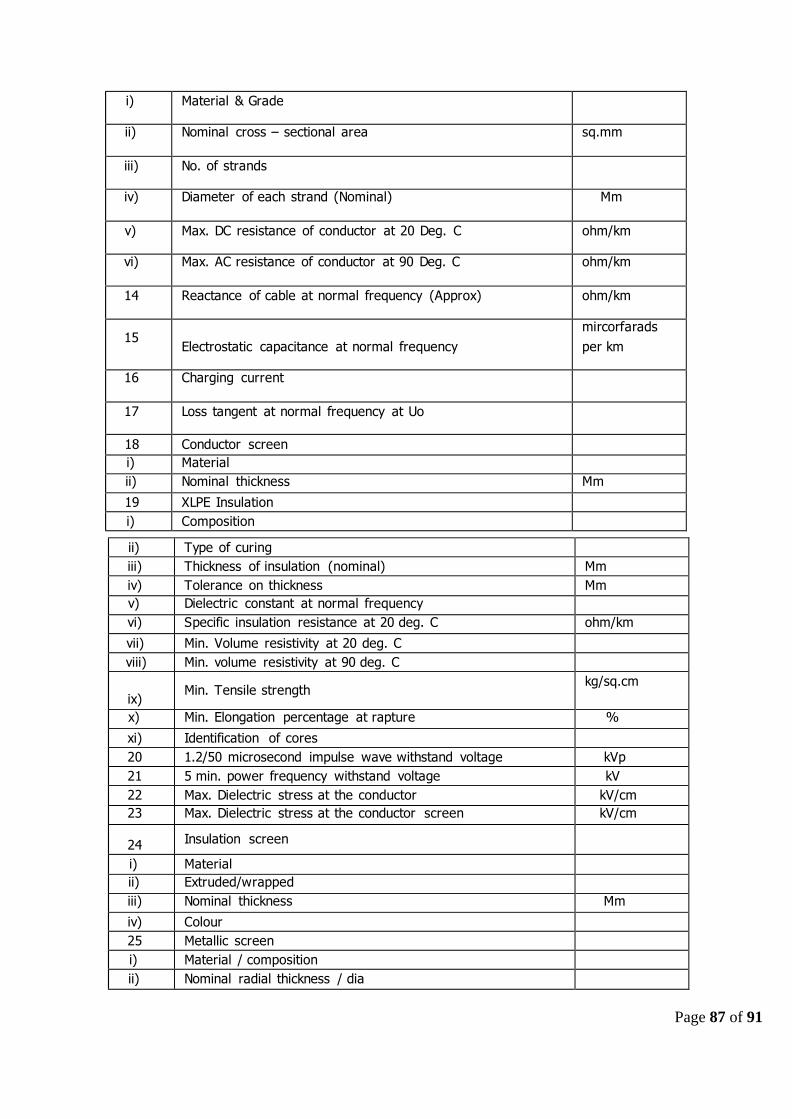
Page 87 of 91
i) Material & Grade
ii) Nominal cross – sectional area sq.mm
iii) No. of strands
iv) Diameter of each strand (Nominal) Mm
v) Max. DC resistance of conductor at 20 Deg. C ohm/km
vi) Max. AC resistance of conductor at 90 Deg. C ohm/km
14 Reactance of cable at normal frequency (Approx) ohm/km
15
Electrostatic capacitance at normal frequency
mircorfarads
per km
16 Charging current
17 Loss tangent at normal frequency at Uo
18 Conductor screen
i) Material
ii) Nominal thickness Mm
19 XLPE Insulation
i) Composition
ii) Type of curing
iii) Thickness of insulation (nominal) Mm
iv) Tolerance on thickness Mm
v) Dielectric constant at normal frequency
vi) Specific insulation resistance at 20 deg. C ohm/km
vii) Min. Volume resistivity at 20 deg. C
viii) Min. volume resistivity at 90 deg. C
ix)
Min. Tensile strength
kg/sq.cm
x) Min. Elongation percentage at rapture %
xi) Identification of cores
20 1.2/50 microsecond impulse wave withstand voltage kVp
21 5 min. power frequency withstand voltage kV
22 Max. Dielectric stress at the conductor kV/cm
23 Max. Dielectric stress at the conductor screen kV/cm
24 Insulation screen
i) Material
ii) Extruded/wrapped
iii) Nominal thickness Mm
iv) Colour
25 Metallic screen
i) Material / composition
ii) Nominal radial thickness / dia

Page 88 of 91
26 Nominal diameter over metallic screen Mm
27 Nominal radial clearance allowed under metal sheath Mm
28 Type and material of filler
29 Armour
i) Material and type
ii) Dia
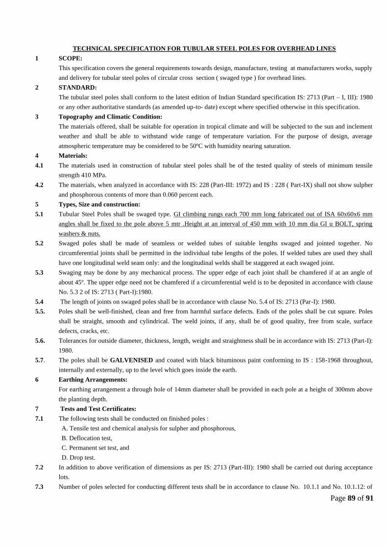
Page 89 of 91
TECHNICAL SPECIFICATION FOR TUBULAR STEEL POLES FOR OVERHEAD LINES
1 SCOPE:
This specification covers the general requirements towards design, manufacture, testing at manufacturers works, supply
and delivery for tubular steel poles of circular cross section ( swaged type ) for overhead lines.
2 STANDARD:
The tubular steel poles shall conform to the latest edition of Indian Standard specification IS: 2713 (Part – I, III): 1980
or any other authoritative standards (as amended up-to- date) except where specified otherwise in this specification.
3 Topography and Climatic Condition:
The materials offered, shall be suitable for operation in tropical climate and will be subjected to the sun and inclement
weather and shall be able to withstand wide range of temperature variation. For the purpose of design, average
atmospheric temperature may be considered to be 50ºC with humidity nearing saturation.
4 Materials:
4.1 The materials used in construction of tubular steel poles shall be of the tested quality of steels of minimum tensile
strength 410 MPa.
4.2 The materials, when analyzed in accordance with IS: 228 (Part-III: 1972) and IS : 228 ( Part-IX) shall not show sulpher
and phosphorous contents of more than 0.060 percent each.
5 Types, Size and construction:
5.1 Tubular Steel Poles shall be swaged type. GI climbing rungs each 700 mm long fabricated out of ISA 60x60x6 mm
angles shall be fixed to the pole above 5 mtr .Height at an interval of 450 mm with 10 mm dia GI u BOLT, spring
washers & nuts.
5.2 Swaged poles shall be made of seamless or welded tubes of suitable lengths swaged and jointed together. No
circumferential joints shall be permitted in the individual tube lengths of the poles. If welded tubes are used they shall
have one longitudinal weld seam only: and the longitudinal welds shall be staggered at each swaged joint.
5.3 Swaging may be done by any mechanical process. The upper edge of each joint shall be chamfered if at an angle of
about 45o. The upper edge need not be chamfered if a circumferential weld is to be deposited in accordance with clause
No. 5.3 2 of IS: 2713 ( Part-I):1980.
5.4 The length of joints on swaged poles shall be in accordance with clause No. 5.4 of IS: 2713 (Par-I): 1980.
5.5. Poles shall be well-finished, clean and free from harmful surface defects. Ends of the poles shall be cut square. Poles
shall be straight, smooth and cylindrical. The weld joints, if any, shall be of good quality, free from scale, surface
defects, cracks, etc.
5.6. Tolerances for outside diameter, thickness, length, weight and straightness shall be in accordance with IS: 2713 (Part-I):
1980.
5.7. The poles shall be GALVENISED and coated with black bituminous paint conforming to IS : 158-1968 throughout,
internally and externally, up to the level which goes inside the earth.
6 Earthing Arrangements:
For earthing arrangement a through hole of 14mm diameter shall be provided in each pole at a height of 300mm above
the planting depth.
7 Tests and Test Certificates:
7.1 The following tests shall be conducted on finished poles :
A. Tensile test and chemical analysis for sulpher and phosphorous,
B. Deflocation test,
C. Permanent set test, and
D. Drop test.
7.2 In addition to above verification of dimensions as per IS: 2713 (Part-III): 1980 shall be carried out during acceptance
lots.
7.3 Number of poles selected for conducting different tests shall be in accordance to clause No. 10.1.1 and No. 10.1.12: of

Page 90 of 91
IS: 2713 (Part-I) 1980.
7.4 Tests shall be carried out before supply of each consignment at the manufacturers woks and test certificates shall be
submitted to the purchaser for approval prior to delivery.
7.5 Re-tests, if any, shall be made in accordance with IS: 2713 (Part-I) 1980.
7.6 Purchaser reserves the right to inspect during manufacturing and depute his representative to inspect/test at the works.
7.7 If any extra cost is required for carrying out the above specified tests, the same shall be borne by the manufacturer.
8 Marking:
8.1 The poles shall be marked with designation, manufacturer’s identification, year of manufacture and name of the
purchaser: APDCL (IPDS)
8.2 The poles may also be marked with the ISI certification mark.
9 Guaranteed technical particulars:
9.1 The manufacturer shall furnish all necessary guaranteed technical particulars in the prescribed Performa enclosed
hereinafter.
10 Performance:-
10.1 The manufacturer shall furnish a list of the major supplies effected during the last 3 (three) years indicating the volume
of supply and actual delivery dates.
10.2 Manufacturer may not be considered if the past manufacturing experience is found to be less that 3 (three) years.
11 Deviation:
Any deviation in technical specification shall be clearly indicated with sufficient reasons thereof. Purchaser shall
however reserve the right to accept and/or reject the same without assigning any reasons what-so-ever.
ANNEXURE –‘A’
SPECIFIC TECHNICAL REQUIREMENTS FORTUBULAR STEEL POLES : SWAGED TYPE
8.5 meters long 11 meters
long
14.5 meters
long 12 meters long
1) Standard IS: 2713 ( Pat-I and III): 1980 as amended upto date
2) Type of Pole Swaged Type
3) Designation 410 SP 22 410 SP 52 410 SP 76 410 SP 60
4) Overall Length 8.5 meters 11 meters 14.5 meters 12 meters
5) Planting depth 1.5 meters 1.8 meters 2.0 meters 2.0 meters
6) Height above ground 7.0 meters 9.2 meters 12.5 meters 10.0 meters
7) Effective length of
Each section.
a) Bottom 5.0 meters 5.6 meters 6.50 meters 5.80 meters
b) Middle 1.75 meters 2.7 meters 4.00 meters 3.10 meters
c) Top 1.75 meters 2.7 meters 4.00 meters 3.10 meters
8) Outside diameter and
Thickness of each
Section.
a) Bottom 165.1x 4.50 mm 165.1x4.50
mm 219.1x5.90 mm 165.1x5.40mm
b) Middle 139.7x4.50 mm 139.7x4.50
mm 193.7x4.85 mm 139.7x4.50 mm
c) Top 114.3x3.65 mm 114.3x3.65 165.1x4.50 mm 114.3x3.65 mm
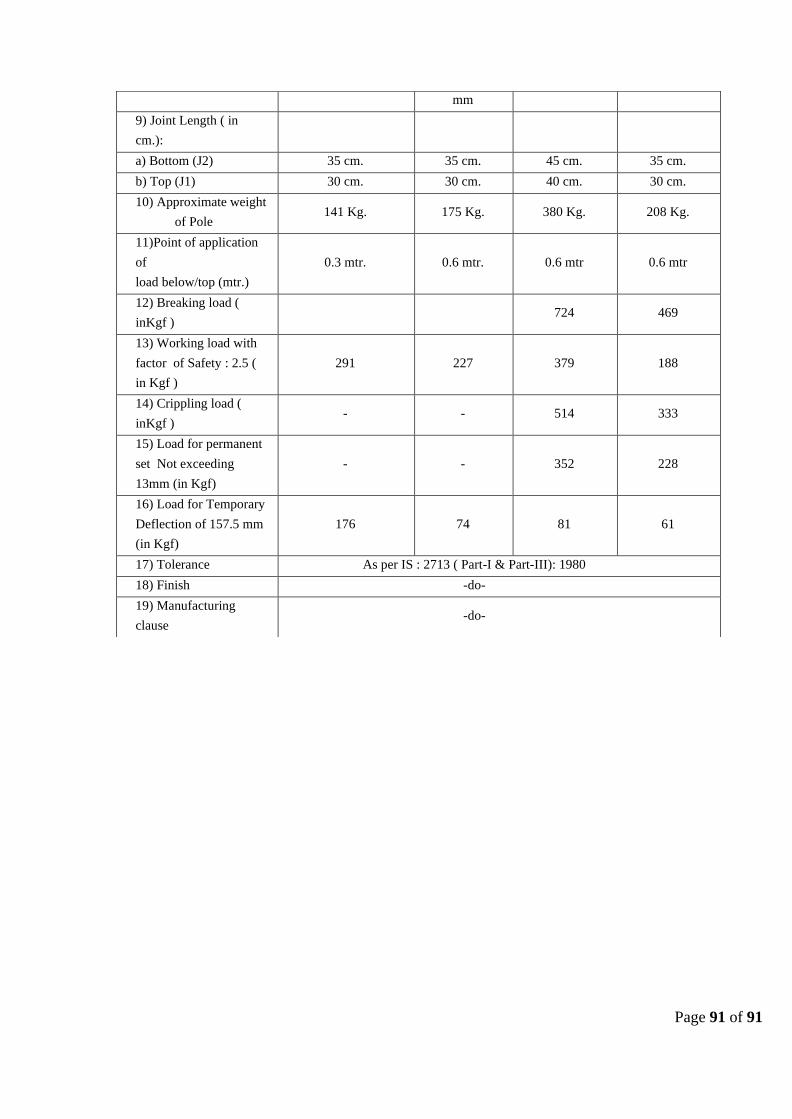
Page 91 of 91
mm
9) Joint Length ( in
cm.):
a) Bottom (J2) 35 cm. 35 cm. 45 cm. 35 cm.
b) Top (J1) 30 cm. 30 cm. 40 cm. 30 cm.
10) Approximate weight
of Pole 141 Kg. 175 Kg. 380 Kg. 208 Kg.
11)Point of application
of
load below/top (mtr.)
0.3 mtr. 0.6 mtr. 0.6 mtr 0.6 mtr
12) Breaking load (
inKgf ) 724 469
13) Working load with
factor of Safety : 2.5 (
in Kgf )
291 227 379 188
14) Crippling load (
inKgf ) - - 514 333
15) Load for permanent
set Not exceeding
13mm (in Kgf)
- - 352 228
16) Load for Temporary
Deflection of 157.5 mm
(in Kgf)
176 74 81 61
17) Tolerance As per IS : 2713 ( Part-I & Part-III): 1980
18) Finish -do-
19) Manufacturing
clause -do-