DESIGN AND ANALYSIS OF WINGLETS WITH MODIFIED TIP ...
13
AIJREAS VOLUME 1, ISSUE 10 (2016, OCT) (ISSN-2455-6300) ONLINE ANVESHANA’S INTERNATIONAL JOURNAL OF RESEARCH IN ENGINEERING AND APPLIED SCIENCES ANVESHANA’S INTERNATIONAL JOURNAL OF RESEARCH IN ENGINEERING AND APPLIED SCIENCES EMAIL ID: [email protected] , WEBSITE: www.anveshanaindia.com 152 DESIGN AND ANALYSIS OF WINGLETS WITH MODIFIED TIP TO ENHANCE PERFORMANCE BY REDUCING DRAG T.SUMANTH 14R31D0410, M.Tech, Nova College Of Engineering And Technology, Jafferguda, Hayatnagar, Hyderabad Dr.D.RAMESH Principal, Nova College Of Engineering And Technology, Jafferguda, Hayatnagar, Hyderabad ABSTRACT: Winglets being a small structure play an important role in reducing the induced drag in Aircraft . Many types of winglets have been designed and their significance in reducing the Drag is published. One of the main objectives of this master thesis work is to study about the winglet design and about their contribution in reducing induced drag. A brief overview of wing tip devices and their performance from the manufacturers as well as from airliner’s point of view are discussed. Moreover, the role of winglet in reducing the drag of commercial civil jet aircraft is studied and the percentage of drag reduction is calculated by a conceptual approach . A320 specifications are taken to perform induced drag reduction calculation with and without winglets. Indeed, the total drag count reduced with the help of winglets accounts for additional payload which will be an advantage for the aircraft operator. Reducing the process time in design is one of the important criteria for any field and hence automation with help of CAD tools is very significant in reducing time. This study also aims at developing an automated model for different types of winglets and wing tip devices with the help of CAD technology focused on reducing design time during the initial design process . Knowledge based approach is used in this work and all the models are parameterized so e ach model could be varied with associated parameters. The generic model created would take different shapes and switches between different types of wing tip devices as per the user’s requirement with the help of available parameters. Knowledge Pattern (KP) approach is used to develop the automation process. User Defined Features (UDFs) are created for each type of winglet and tip devices. CATIA V5 R18 software is used to develop the models of winglets and tip devices. INTRODUCTION WING: A wing is a type of fin with a surface that produces aerodynamic force for flight or propulsion through the atmosphere, or through another gaseous or liquid fluid. As such, wings have an airfoil shape, a streamlined cross-sectional shape producing a useful lift to drag ratio. The word "wing" from the Old Norse vængr for many centuries referred mainly to the foremost limbs of birds (in addition to the architectural aisle.) But in recent centuries the word's meaning has extended to include lift producing appendages of insects, bats, pterosaurs, boomerangs, some sail boats and aircraft, or the inverted airfoil on a race car that generates a downward force to increase traction.
-
Upload
khangminh22 -
Category
Documents
-
view
2 -
download
0
Transcript of DESIGN AND ANALYSIS OF WINGLETS WITH MODIFIED TIP ...

AIJREAS VOLUME 1, ISSUE 10 (2016, OCT) (ISSN-2455-6300) ONLINE
ANVESHANA’S INTERNATIONAL JOURNAL OF RESEARCH IN ENGINEERING AND APPLIED SCIENCES
ANVESHANA’S INTERNATIONAL JOURNAL OF RESEARCH IN ENGINEERING AND APPLIED SCIENCES
EMAIL ID: [email protected] , WEBSITE: www.anveshanaindia.com 152
DESIGN AND ANALYSIS OF WINGLETS WITH MODIFIED TIP TO
ENHANCE PERFORMANCE BY REDUCING DRAG
T.SUMANTH
14R31D0410, M.Tech, Nova College Of
Engineering And Technology, Jafferguda,
Hayatnagar, Hyderabad
Dr.D.RAMESH
Principal, Nova College Of Engineering And
Technology, Jafferguda, Hayatnagar, Hyderabad
ABSTRACT:
Winglets being a small structure play an
important role in reducing the induced drag
in Aircraft . Many types of winglets have
been designed and their significance in
reducing the Drag is published. One of the
main objectives of this master thesis work is to
study about the winglet design and about their
contribution in reducing induced drag. A
brief overview of wing tip devices and their
performance from the manufacturers as well as
from airliner’s point of view are discussed.
Moreover, the role of winglet in reducing the
drag of commercial civil jet aircraft is studied
and the percentage of drag reduction is
calculated by a conceptual approach . A320
specifications are taken to perform induced
drag reduction calculation with and without
winglets. Indeed, the total drag count reduced
with the help of winglets accounts for additional
payload which will be an advantage for the
aircraft operator.
Reducing the process time in design is one of
the important criteria for any field and hence
automation with help of CAD tools is very
significant in reducing time. This study also
aims at developing an automated model for
different types of winglets and wing tip
devices with the help of CAD technology
focused on reducing design time during the
initial design process . Knowledge based
approach is used in this work and all the models
are parameterized so e ach model could be
varied with associated parameters. The generic
model created would take different shapes and
switches between different types of wing tip
devices as per the user’s requirement with the
help of available parameters. Knowledge
Pattern (KP) approach is used to develop the
automation process. User Defined Features
(UDFs) are created for each type of winglet
and tip devices. CATIA V5 R18 software is
used to develop the models of winglets and
tip devices.
INTRODUCTION
WING:
A wing is a type of fin with a surface that
produces aerodynamic force for flight or
propulsion through the atmosphere, or
through another gaseous or liquid fluid. As
such, wings have an airfoil shape, a
streamlined cross-sectional shape producing
a useful lift to drag ratio.
The word "wing" from the Old Norse vængr
for many centuries referred mainly to the
foremost limbs of birds (in addition to the
architectural aisle.) But in recent centuries
the word's meaning has extended to include
lift producing appendages of insects, bats,
pterosaurs, boomerangs, some sail boats and
aircraft, or the inverted airfoil on a race car
that generates a downward force to increase
traction.
AIJREAS VOLUME 1, ISSUE 10 (2016, OCT) (ISSN-2455-6300) ONLINE
ANVESHANA’S INTERNATIONAL JOURNAL OF RESEARCH IN ENGINEERING AND APPLIED SCIENCES
ANVESHANA’S INTERNATIONAL JOURNAL OF RESEARCH IN ENGINEERING AND APPLIED SCIENCES
EMAIL ID: [email protected] , WEBSITE: www.anveshanaindia.com 153
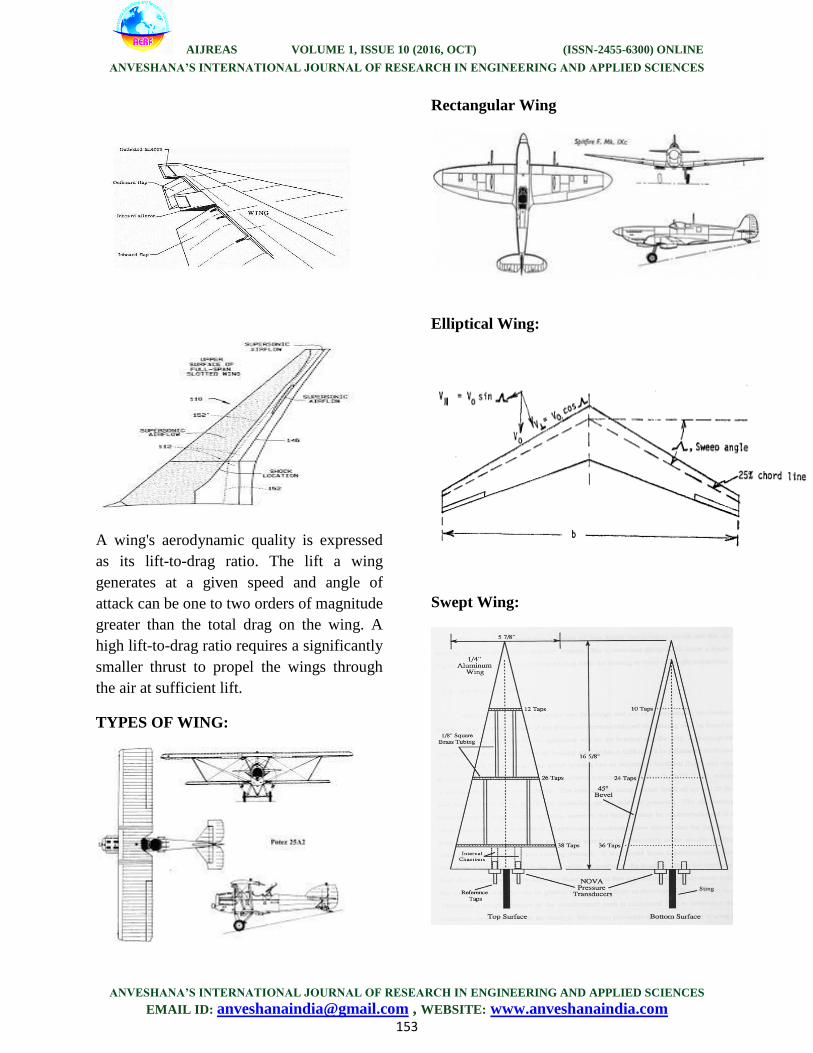
A wing's aerodynamic quality is expressed
as its lift-to-drag ratio. The lift a wing
generates at a given speed and angle of
attack can be one to two orders of magnitude
greater than the total drag on the wing. A
high lift-to-drag ratio requires a significantly
smaller thrust to propel the wings through
the air at sufficient lift.
TYPES OF WING:
Rectangular Wing
Elliptical Wing:
Swept Wing:
AIJREAS VOLUME 1, ISSUE 10 (2016, OCT) (ISSN-2455-6300) ONLINE
ANVESHANA’S INTERNATIONAL JOURNAL OF RESEARCH IN ENGINEERING AND APPLIED SCIENCES
ANVESHANA’S INTERNATIONAL JOURNAL OF RESEARCH IN ENGINEERING AND APPLIED SCIENCES
EMAIL ID: [email protected] , WEBSITE: www.anveshanaindia.com 154
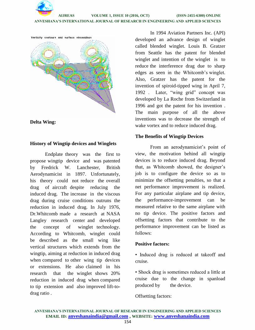
Delta Wing:
History of Wingtip devices and Winglets
Endplate theory was the first to
propose wingtip device and was patented
by Fredrick W. Lanchester, British
Aerodynamicist in 1897. Unfortunately,
his theory could not reduce the overall
drag of aircraft despite reducing the
induced drag. The increase in the viscous
drag during cruise conditions outruns the
reduction in induced drag. In July 1976,
Dr.Whitcomb made a research at NASA
Langley research center and developed
the concept of winglet technology.
According to Whitcomb, winglet could
be described as the small wing like
vertical structures which extends from the
wingtip, aiming at reduction in induced drag
when compared to other wing tip devices
or extensions. He also claimed in his
research that the winglet shows 20%
reduction in induced drag when compared
to tip extension and also improved lift-to-
drag ratio .
In 1994 Aviation Partners Inc. (API)
developed an advance design of winglet
called blended winglet. Louis B. Gratzer
from Seattle has the patent for blended
winglet and intention of the winglet is to
reduce the interference drag due to sharp
edges as seen in the Whitcomb’s winglet.
Also, Gratzer has the patent for the
invention of spiroid-tipped wing in April 7,
1992 . Later, “wing grid” concept was
developed by La Roche from Switzerland in
1996 and got the patent for his invention .
The main purpose of all the above
inventions was to decrease the strength of
wake vortex and to reduce induced drag.
The Benefits of Wingtip Devices
From an aerodynamicist’s point of
view, the motivation behind all wingtip
devices is to reduce induced drag. Beyond
that, as Whitcomb showed, the designer’s
job is to configure the device so as to
minimize the offsetting penalties, so that a
net performance improvement is realized.
For any particular airplane and tip device,
the performance-improvement can be
measured relative to the same airplane with
no tip device. The positive factors and
offsetting factors that contribute to the
performance improvement can be listed as
follows:
Positive factors:
• Induced drag is reduced at takeoff and
cruise.
• Shock drag is sometimes reduced a little at
cruise due to the change in spanload
produced by the device.
Offsetting factors:
AIJREAS VOLUME 1, ISSUE 10 (2016, OCT) (ISSN-2455-6300) ONLINE
ANVESHANA’S INTERNATIONAL JOURNAL OF RESEARCH IN ENGINEERING AND APPLIED SCIENCES
ANVESHANA’S INTERNATIONAL JOURNAL OF RESEARCH IN ENGINEERING AND APPLIED SCIENCES
EMAIL ID: [email protected] , WEBSITE: www.anveshanaindia.com 155
• Profile drag is increased due to:
– Increased wetted area.
– Junction flows, high sectional loadings,
etc.
• Weight is increased due to:
– The weight of the device itself.
– The weight of attachment fittings.
– Increases in the weight of the existing
wing structure due to increases in static
loads and to meet flutter and fatigue
requirements.
A net performance improvement is
satisfying to an engineer, but for an airplane
manufacturer or operator the objective is to
realize the kind of bottom-line benefits that
translate into dollars. Here is a list of the
potential bottom-line benefits of tip devices,
in rough order of importance, and some
offsetting factors:
Benefits:
• Improved performance:
– Reduced fuel burn.
– Increased maximum range.
– Reduced takeoff field length due to
improved second segment climb.
– Increased cruise altitude due to improved
buffet boundary.
– Increased cruise speed due to modest
increase in MDD
– Reduced takeoff noise.
• Meet gate clearance with minimal
performance penalty.
• Appearance and product differentiation.
Offsetting factors:
• Increased cost (development, recurring,
and purchase).
• Increased development risk.
Another possible benefit that has
sometimes been put forward is that tip
devices can reduce the strength of the vortex
wake, with the implication that this could
lead improved safety or reduced separation
distances on landing approach or takeoff.
This one is not included on our list because
the reduction in vortex strength is typically
very small, and the resulting benefit is
insignificant.
The main positive factor that makes
the benefits possible is the reduction of
induced drag. In the next section we discuss
the physics of induced-drag reduction and
the implications for the configuration of
effective wingtip devices.
The vortex wake
A distinctive feature of the wing-
induced flowfield that is prominent in
discussions of induced drag, and that plays a
role in the quantitative theory, is the trailing
vortex wake. The nature of the vortex wake
and its role in induced drag have been a
source of some serious misunderstandings,
and these erroneous ideas have resulted in
numerous proposals for tip-device concepts
that cannot work as their proponents claim.
We therefore take care in the following

AIJREAS VOLUME 1, ISSUE 10 (2016, OCT) (ISSN-2455-6300) ONLINE
ANVESHANA’S INTERNATIONAL JOURNAL OF RESEARCH IN ENGINEERING AND APPLIED SCIENCES
ANVESHANA’S INTERNATIONAL JOURNAL OF RESEARCH IN ENGINEERING AND APPLIED SCIENCES
EMAIL ID: [email protected] , WEBSITE: www.anveshanaindia.com 156
discussion to develop a correct
understanding of the vortex wake and its
role and to point out where some of the
erroneous concepts went wrong.
The vortex wake starts as a vortex
sheet shed from the trailing edge of the wing
as a byproduct of producing the flow pattern
shown in Figure 3.1. To understand the
origin of the vortex sheet, look at the
velocity vectors immediately above and
below the wing in Figure 3.1. Note that the
vertical components of these velocities are
the same above and below the wing, but that
the horizontal (spanwise) components
undergo a "jump,” from the outboard
direction below the wing to the inboard
direction above the wing. It is this jump in
the spanwise velocity component that
constitutes the vortex sheet that ends up
streaming back from the wing trailing edge.
The vortex sheet is a necessary part of the
flowfield because the conservation laws of
fluid mechanics dictate that the wing cannot
produce the general flow pattern of Figure
3.1 without also producing the jump in
spanwise velocity. On an intuitive level, the
spanwise-velocity jump can be understood
as being a result of the tendency of air to
flow away from the high pressure under the
wing toward the low pressure above the
wing. The wing itself presents an obstacle to
this motion and deflects it in the spanwise
direction.
COMPUTER AIDED DESIGN:
Aircraft design being a complex process has
many phases in which Computer Aided
Design (CAD) plays a significant role.
Many aircraft manufacturers such as
Boeing, Dassault, and Airbus have been
adopting the CAD software tool like CATIA
in order to minimize the lead time and to
avoid prolonged duration in design
process. CAD combined with Knowledge
based engineering (KBE) aimed at
reducing time the taken for design process
in case of repetition . Studies have been
done on developing parameterized CAD
models focusing to optimize the given
model with less duration of time . D
operator and K operator were the two
approaches developed with CAE tools for
making repetitive process. VB script is
associated with D operator, whereas
Knowledge Pattern (KP) developed based
on C++ programming language, is under
the K operator approach .
KP has been implemented in Dassault
systems software CATIA V5 R16. One of
the main disadvantages in VB script for
dynamic instantiation of the models is
longer time consumption for scripting.
Studies revealed that automation for
creating models and patterns dynamically
were done based on Knowledge Pattern
script where the time consumed for
pattern creation and scripting were much
lesser than VB approach.

AIJREAS VOLUME 1, ISSUE 10 (2016, OCT) (ISSN-2455-6300) ONLINE
ANVESHANA’S INTERNATIONAL JOURNAL OF RESEARCH IN ENGINEERING AND APPLIED SCIENCES
ANVESHANA’S INTERNATIONAL JOURNAL OF RESEARCH IN ENGINEERING AND APPLIED SCIENCES
EMAIL ID: [email protected] , WEBSITE: www.anveshanaindia.com 157
Design Requirements
Because a winglet does not operate
exactly as a wing does, the performance
benefits if the airfoil used is designed
specifically for that purpose. To do this,
it is necessary to fully determine the
operational conditions of the winglet and
how they relate to those of the wing.
Because the principal benefit of a
winglet is in climb, he airfoil
performance at low flight speeds is of
primary importance. Thus, the airfoil must
generate the maximum lift coefficient
required by the winglet as the aircraft main
wing approaches stall. Likewise, low-drag
performance over the entire operating
range is mportant, but must be considered
in conjunction with other constraints.
As the profile drag increases with
velocity squared, a large drag coefficient
at low lift coefficients would severely
penalize the aircraft performance at higher
flight speeds. This drives the low lift-
coefficient portion of the airfoil drag
polar. The degree to which these
considerations influence the overall
performance is difficult to ascertain
without considering the entire flight profile
of the sailplane. To do this, a method of
sailplane performance has been developed
that can be used to determine how much of a
gain at low speed is needed to offset a
loss at highspeed.
Computer-aided design (CAD) is the use of
computer systems to assist in the creation,
modification, analysis, or optimization of a
design. CAD software is used to increase the
productivity of the designer, improve the
quality of design, improve communications
through documentation, and to create a
database for manufacturing.CAD output is
often in the form of electronic files for print,
machining, or other manufacturing
operations.
Computer-aided design is used in many
fields. Its use in designing electronic
systems is known as Electronic Design
Automation, or EDA. In mechanical design
it is known as Mechanical Design
Automation (MDA) or computer-aided
drafting (CAD), which includes the process
of creating a technical drawing with the use
of computer software.
CATIA V5 R16
(Computer Aided Three Dimensional
Interactive Application)
The 3D CAD system CATIA V5 was
introduced in 1999 by Dassault Systems.
Replacing CATIA V4, it represented a
completely new design tool showing
fundamental differences to its predecessor.
The user interface, now featuring MS
Windows layout, allows an easy integration
of common software packages such as MS
Office, several graphic programs or SAP-R3
products (depending on the IT environment)
and others.
CATIA (Computer Aided Three-
dimensional Interactive Application) (in
English usually pronounced /kəˈtiə/) is a
multi-platform CAD/CAM/CAE
commercial software suite developed by the
French company Dassault Systèmes. Written
in the C++ programming language, CATIA
is the cornerstone of the Dassault Systèmes
product lifecycle management software
suite.

AIJREAS VOLUME 1, ISSUE 10 (2016, OCT) (ISSN-2455-6300) ONLINE
ANVESHANA’S INTERNATIONAL JOURNAL OF RESEARCH IN ENGINEERING AND APPLIED SCIENCES
ANVESHANA’S INTERNATIONAL JOURNAL OF RESEARCH IN ENGINEERING AND APPLIED SCIENCES
EMAIL ID: [email protected] , WEBSITE: www.anveshanaindia.com 158
CATIA competes in the high-end
CAD/CAM/CAE market with Creo
Elements/Pro and NX (Unigraphics).
After the airfoil in the curve is created the”
multisection” command is being used to
connect the three airfoil to create the
following design.
The above picture only shows the design
without spline
The picture with spline and sweep of angle
115 degree’s is as follows.
Now this wireframe is subjected to create a
solid model. So to create a solid model of
above wireframe design the design is to be
thoroughly checked for an unclosed surface,
because the ”catia” won’t allow the open
surface to create a solid body.
So the design is checked for any open
surfaces . So if there are any we use “spline
command” to close the structure.
Here the different airfoils are selected and
created as one domain using “multisection”
After the airfoil in the curve is created the”
multisection” command is being used to
connect the three airfoil to create the
following design.
The whole angle is almost 360 degree but it
is arranged according to our assumptions.

AIJREAS VOLUME 1, ISSUE 10 (2016, OCT) (ISSN-2455-6300) ONLINE
ANVESHANA’S INTERNATIONAL JOURNAL OF RESEARCH IN ENGINEERING AND APPLIED SCIENCES
ANVESHANA’S INTERNATIONAL JOURNAL OF RESEARCH IN ENGINEERING AND APPLIED SCIENCES
EMAIL ID: [email protected] , WEBSITE: www.anveshanaindia.com 159
MESHING THE WINGLETS using
ANSYS 14.0 WORKBENCH
ANSYS, Inc. is an engineering simulation
software (computer-aided engineering, or
CAE) developer that is headquartered south
of Pittsburgh in the Southpointe business
park in Cecil Township, Pennsylvania,
United States.
ANSYS was listed on the NASDAQ
stock exchange in 1996. In late 2011,
ANSYS received the highest possible score
on its SmartSelect Composite Ratings
according to Investor's Business Daily. The
organization reinvests 15 percent of its
revenues each year into research to
continually refine the software.
ANSYS 14.0 delivers innovative,
dramatic simulation technology advances in
every major physics discipline, along with
improvements in computing speed and
enhancements to enabling technologies such
as geometry handling, meshing and post-
processing. These advancements alone
represent a major step ahead on the path
forward in Simulation Driven Product
Development. But ANSYS has reached even
further by delivering all this technology in
an innovative simulation framework
,ANSYS Workbench 2.0.The ANSYS
Workbench environment is the glue that
binds the simulation process; this has not
changed with version 2.0.
In the original ANSYS Workbench,
the user interacted with the analysis as a
whole using the platform’s project page:
launching the various applications and
tracking the resulting files employed in the
process of creating an analysis. Tight
integration between the component
application yielded unprecedented ease of
use for setup and solution of even complex
multiphysics simulations. In ANSYS 14.0,
while the core applications may seem
familiar, they are bound together via the
innovative project page that introduces the
concept of the project schematic.
Mesh-generate
After this export the file to fluent.
The mesh file looks like the figure below

AIJREAS VOLUME 1, ISSUE 10 (2016, OCT) (ISSN-2455-6300) ONLINE
ANVESHANA’S INTERNATIONAL JOURNAL OF RESEARCH IN ENGINEERING AND APPLIED SCIENCES
ANVESHANA’S INTERNATIONAL JOURNAL OF RESEARCH IN ENGINEERING AND APPLIED SCIENCES
EMAIL ID: [email protected] , WEBSITE: www.anveshanaindia.com 160
ANALYSIS USING
ANSYS FLUENT
ANSYS Fluent software contains
the broad physical modeling capabilities
needed to model flow, turbulence, heat
transfer, and reactions for industrial
applications ranging from air flow over an
aircraft wing to combustion in a furnace,
from bubble columns to oil platforms, from
blood flow to semiconductor manufacturing,
and from clean room design to wastewater
treatment plants. Special models that give
the software the ability to model in-cylinder
combustion, aeroacoustics, turbomachinery,
and multiphase systems have served to
broaden its reach.
View larger imageInternal combustion
engine modeled using ANSYS Fluent
Today, thousands of companies throughout
the world benefit from the use of ANSYS
Fluent software as an integral part of the
design and optimization phases of their
product development. Advanced solver
technology provides fast, accurate CFD
results, flexible moving and deforming
meshes, and superior parallel scalability.
User-defined functions allow the
implementation of new user models and the
extensive customization of existing ones.
The interactive solver setup, solution and
post-processing capabilities of ANSYS
Fluent make it easy to pause a calculation,
examine results with integrated post-
processing, change any setting, and then
continue the calculation within a single
application. Case and data files can be read
into ANSYS CFD-Post for further analysis
with advanced post-processing tools and
side-by-side comparison of different cases.
.

AIJREAS VOLUME 1, ISSUE 10 (2016, OCT) (ISSN-2455-6300) ONLINE
ANVESHANA’S INTERNATIONAL JOURNAL OF RESEARCH IN ENGINEERING AND APPLIED SCIENCES
ANVESHANA’S INTERNATIONAL JOURNAL OF RESEARCH IN ENGINEERING AND APPLIED SCIENCES
EMAIL ID: [email protected] , WEBSITE: www.anveshanaindia.com 161
FIG :ANSYS Fluent adjoint solver
indicates the necessary shape changes to
ensure maximum down force for a race
car
The combination of these benefits with the
extensive range of physical modeling
capabilities and the fast, accurate CFD
results that ANSYS Fluent software has to
offer results in one of the most
comprehensive software packages for CFD
modeling available in the world today. A
native two-way connection to ANSYS
structural mechanics products allows capture
of even the most complex fluid–structure
interaction (FSI) problems in the same easy-
to-use environment, saving the need to
purchase, administer or run third-party
coupling software. Other multiphysics
connections include electromagnetic–fluid
coupling.
The flow over a 3d blended winglet after
1000 iterations is as follows
RESULTS AND CONCLUSIONS:
Cases Wth Blended Winglet And Spiroid
Winglet :
As seen in Fig below the largest amount of
turbulence in the flow is associated with the
winglet. The clean wing also produces a
turbulent flow as air flows over the wingtips.
The spiroid wingtip exhibits the least
amount of disruption aft of the tip, due to its
more aerodynamic design.
FIG: TURBULENT FLOW ASSOCIATED
WITH WINGLETS

AIJREAS VOLUME 1, ISSUE 10 (2016, OCT) (ISSN-2455-6300) ONLINE
ANVESHANA’S INTERNATIONAL JOURNAL OF RESEARCH IN ENGINEERING AND APPLIED SCIENCES
ANVESHANA’S INTERNATIONAL JOURNAL OF RESEARCH IN ENGINEERING AND APPLIED SCIENCES
EMAIL ID: [email protected] , WEBSITE: www.anveshanaindia.com 162
The vorticity of the vortex wake for each
wingtip is plotted in Fig. below. The range
of the plot extends from the wingtip of each
wing to the boundary of the flow domain, in
the direction of the freestream. Noticeable in
Fig below is the dramatic reduction of
vorticity in the wake region associated with
the spiroid wingtip model. The plot indicates
that the vorticity associated with the clean
wing and the wing with winglets
configurations share a similar flow pattern.
However, upon closer inspection of the plot
the vorticity magnitude in the vortex wake
of the clean wing is
more erratic and turbulent than for the wing
with winglets. As illustrated in the previous
vector and contour plots, the wing with
winglets configuration produces strong
wingtip vortices, however they are less
turbulent and more concentrated than the
clean wing configuration.
The graph is shown below.
FIG: REDUCTION IN VORTICITY
GRAPH OF DRAG CONVERGENT (Cd
VS ITERATIONS):
These are the two graphs below for the
blended winglet drag and lift respectively.
Now observing this graph, at the beginning
as we can see the drag is far more greater
than any in the field represented.
At the beginning of the flow of velocity
133km/sec the drag gradually increases to
the critical point and later the drag on the
surface of the body, decreases gradually
until it reaches a certain point where the
drag is standard until the converging of the
structure.we can conclude that from drag
graph the reduction in drag gradually.
By reducing the drag we can increase the lift
and we get the more thrust and this will help
the aircraft to reduce take off distance and
increase the fuel efficiency.
By reducing the drag we can increase the
lift and we get the more thrust this will help
the aircraft to reduce take off distance and
increase the fuel efficiency.
The lift graph below explains how the lift is
generated is far more efficient than the other
wings with no wingtip devices.

AIJREAS VOLUME 1, ISSUE 10 (2016, OCT) (ISSN-2455-6300) ONLINE
ANVESHANA’S INTERNATIONAL JOURNAL OF RESEARCH IN ENGINEERING AND APPLIED SCIENCES
ANVESHANA’S INTERNATIONAL JOURNAL OF RESEARCH IN ENGINEERING AND APPLIED SCIENCES
EMAIL ID: [email protected] , WEBSITE: www.anveshanaindia.com 163
Hence the lift convergence graph explains as
iterations increases the performance against
drag.
These are the results of spiroid winglet this
also reduce the induce drag this will help in
reduce the take off distance, weaks and de-
strength the vertices.
When we observe the both blended and
spiroid winglets blended winglet reduce the
induced drag more effectively then the
spiroid winglet
Conclusion/Recommendations/
Assumptions :
The present study serves as a
preliminary investigation into the
aerodynamic effects of different wingtip
configurations on the wingtip vortices
generated as a result of the induced drag on
a wing. In addition, the advantages and
disadvantages of 3-D finite wings with
winglets and spiroid wingtip wing
configurations were investigated. The results
presented in this study reveal two methods
for reducing wingtip vortices and,
consequently, the induced drag on a 3-D
wing.
This study has shown that
clean wing configurations, i.e., wings
without wingtip devices, produce the highest
vorticity magnitudes when compared to
wing configurations that employ either
winglets or spiroid wingtip designs. The
vortex wake generated by clean wing
configurations reduce the aspect ratio of the
wing, thereby increasing the induced drag
on the wing. The winglet design employed
in this study demonstrate the potential to
produce a component of force in the thrust
direction of the aircraft by concentrating the
otherwise turbulent and chaotic vortex flow
behind the wingtips into a more energy-
efficient flow, thereby counteracting the
drag on the wing.
Alternatively, spiroid wingtips
reduce the overall magnitude of the tip
vortices, thereby reducing the induced drag
on the wing. The streamline design of the
spiroid wingtips provide less resistance to
the flow over the wingtips and, in this way,
conserve the energy of the flow. The results
of this preliminary study suggest that wings
designed with winglets or spiroid wingtips

AIJREAS VOLUME 1, ISSUE 10 (2016, OCT) (ISSN-2455-6300) ONLINE
ANVESHANA’S INTERNATIONAL JOURNAL OF RESEARCH IN ENGINEERING AND APPLIED SCIENCES
ANVESHANA’S INTERNATIONAL JOURNAL OF RESEARCH IN ENGINEERING AND APPLIED SCIENCES
EMAIL ID: [email protected] , WEBSITE: www.anveshanaindia.com 164
can indeed reduce the induced drag on a
wing during cruise conditions. This
reduction of the induced drag on an
aircraft’s wing offer advantages in terms of
an aircraft’s performance including
improved fuel efficiency, increased range,
and reduced wing loading.
BIBILOGRAPHY
1. Issn (Online): 2321-3051 Ijrame A Report
On Numerical Investigation Of Wings: With
And Without Winglet By Mohammad
Salahuddin, Mohd Obaid-ur-Rahman , Shaik
Jaleel.
2. 27th AIAA (Applied Aerodynamics
Conference ) Computational Study of the
Vortex Wake Generated by a Three-
Dimensional Wing with Dihedral, Taper,
and Sweep.
3. Numerical Investigation Of Blended
Winglets Effects On Wing Performance.
4.Wingtip Devices by BOEING