Design of Modified Z-Shaped and T-Shaped Microstrip Filter Based on Transfer Function Analysis
14
1 23 Wireless Personal Communications An International Journal ISSN 0929-6212 Wireless Pers Commun DOI 10.1007/s11277-015-2328-z Design of Modified Z-Shaped and T- Shaped Microstrip Filter Based on Transfer Function Analysis Gh. Karimi, H. Siahkamari, F. Khamin Hamedani & A. Lalbakhsh
Transcript of Design of Modified Z-Shaped and T-Shaped Microstrip Filter Based on Transfer Function Analysis
1 23
Wireless Personal CommunicationsAn International Journal ISSN 0929-6212 Wireless Pers CommunDOI 10.1007/s11277-015-2328-z
Design of Modified Z-Shaped and T-Shaped Microstrip Filter Based on TransferFunction Analysis
Gh. Karimi, H. Siahkamari,F. Khamin Hamedani & A. Lalbakhsh

1 23
Your article is protected by copyright and all
rights are held exclusively by Springer Science
+Business Media New York. This e-offprint is
for personal use only and shall not be self-
archived in electronic repositories. If you wish
to self-archive your article, please use the
accepted manuscript version for posting on
your own website. You may further deposit
the accepted manuscript version in any
repository, provided it is only made publicly
available 12 months after official publication
or later and provided acknowledgement is
given to the original source of publication
and a link is inserted to the published article
on Springer's website. The link must be
accompanied by the following text: "The final
publication is available at link.springer.com”.

Wireless Pers CommunDOI 10.1007/s11277-015-2328-z
Design of Modified Z-Shaped and T-Shaped MicrostripFilter Based on Transfer Function Analysis
Gh. Karimi · H. Siahkamari · F. Khamin Hamedani ·A. Lalbakhsh
© Springer Science+Business Media New York 2015
Abstract A new microstrip lowpass filter with compact size, ultra-wide stopband and sharpcutoff frequency is proposed. To achieve an ultra-wide stopband and sharp cutoff frequency,two Z-shaped resonators are added to the filter. To reduce the circuit size of the filter, cur-sive transmission line is also introduced. Moreover, exact equation for the most importanttransmission zeroes are obtained based on LC equivalent circuit and transfer function. Ademonstration filter with 3 dB cut-off frequency at 1.89 has been designed, fabricated andmeasured. The results show a relative stopband bandwidth of 166.3 % (referred to suppressiondegree of 25 dB), and a high figure of merit of 32,613.
Keywords Micriostrip lowpass filter · Ultra wide stopband · Transfer function ·Transmission zero
1 Introduction
High-performance and compact size lowpass filters (LPF) with wide stopband and sharpcutoff frequency are highly demanded in many communication systems especially in wirelessand mobile communications in order to suppress high frequency harmonics [1]. In [2], alowpass filter using shunt open-stubs at feed points of a center fed coupled-line hairpinresonator was presented. The filter has a wide stopband, but the cutoff frequency was notenough sharp. In [3], a lowpass filter was presented circular-shaped patches and open stubsto achieve sharp roll-off and ultra-wide stopband, but the structure of the filter was notsymmetrical. In [4], a new transformed radial stubs (TRSs) with an extended stopband wasintroduced. In [5], a new microstrip lowpass filter with compact size and an ultra-widestopband using both triangular patch resonators and radial patch resonators were presented.
Gh. Karimi (B) · H. SiahkamariElectrical Department, Faculty of Engineering, Razi University, Kermanshah, Irane-mail: [email protected]
F. Khamin Hamedani · A. LalbakhshDepartment of Engineering, Islamic Azad University, Kermanshah Branch, Kermanshah, Iran
123
Author's personal copy
Gh. Karimi et al.
Sharp roll-off and wide stopband lowpass filter based on radial split ring was presented in [6].Authors in [7] proposed a lowpass filter with a very sharp transition band and wide stopband.In [8], coupled-line structure and shunt open stub with compact size and a wide stopbandwere reported. In this paper, a novel lowpass filter with ultra-wide stopband and small size ispresented. To achieve wide stopband, Z-shaped and T-shaped resonators are employed. Thefilter has an ultra-wide stopband from 2.06 GHz up to 20 GHz with large attenuation of morethan 25 dB.
2 Analytical Method
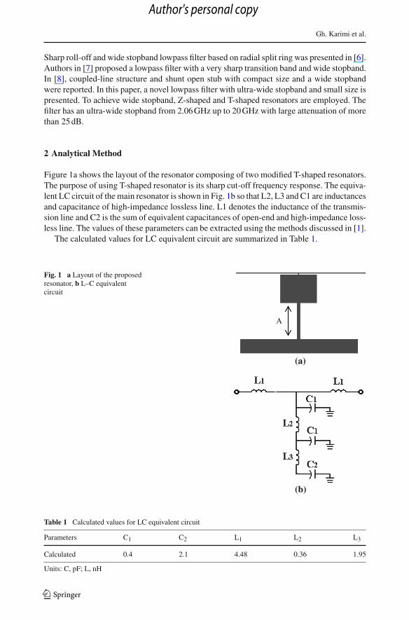
Figure 1a shows the layout of the resonator composing of two modified T-shaped resonators.The purpose of using T-shaped resonator is its sharp cut-off frequency response. The equiva-lent LC circuit of the main resonator is shown in Fig. 1b so that L2, L3 and C1 are inductancesand capacitance of high-impedance lossless line. L1 denotes the inductance of the transmis-sion line and C2 is the sum of equivalent capacitances of open-end and high-impedance loss-less line. The values of these parameters can be extracted using the methods discussed in [1].
The calculated values for LC equivalent circuit are summarized in Table 1.
Fig. 1 a Layout of the proposedresonator, b L–C equivalentcircuit
(a)
(b)
A
Table 1 Calculated values for LC equivalent circuit
Parameters C1 C2 L1 L2 L3
Calculated 0.4 2.1 4.48 0.36 1.95
Units: C, pF; L, nH
123
Author's personal copy

Design of Modified Z-Shaped and T-Shaped Microstrip Filter
Fig. 2 a Frequency response ofthe modified T-shaped resonators.b EM and circuit simulationresults of the proposed resonator
The EM and equivalent circuit simulation results of modified T-shaped resonators are ingood agreement as shown in Fig. 2a. Figure 2b shows the frequency response of the modifiedT-shaped resonators, which has two transmission zeroes at 2.4 and 13.1 GHz with 25.4 and30.2 dB attenuation level respectively. Since the cut-off frequency and sharpness in transitionband are controlled with the first transmission zero, the first transmission zero affects moreimportant than another one.
In this work, we utilized LC model and transfer function for the calculation of the firsttransmission zero. Transfer function is extracted from LC circuit in Eq. (1). r in Eq. (1) refersto resistance of matching. The transmission zero can be calculated in Eq. (2) using the transferfunction in Eq. (1).
vo
vi= ar
(r + L1s)(2a + r + L1S)(1)
where
a = 1 + C1L2s2 + C2 L2s2 + C2 L3s2 + C1C2G2 L4s4
2C1s + C2s + C21 L2s3 + C1C2 L2s3 + 2C1C2 L3s3 + C2
1 C2 L2 L3s5
123
Author's personal copy

Gh. Karimi et al.
Fig. 3 Frequency response ofthe modified T-shaped resonatorswith changing L3 and A
Fig. 4 a Layout of the proposedZ-shaped resonator, b L–Cequivalent circuit
f z =
√−1
C1 L2− 1
C1 L3− 1
C2 L3−
√−4C1C2 L2 L3+(C1 L2+C2 L2+C2 L3)2
C1C2 L2 L3
2√
2π(2)
As can be seen in Eq. (2), the location of transmission zero can be adjusted by changingthe capacitances and inductances values. For instance, if L3 changes to 1.5, 1.95, 2.7 nH, thedimension of A (as shown in Fig. 1) will change to 3, 3.8 and 5 mm respectively, having fzat 2.71, 2.41and 2.11 GHz respectively, as shown in Fig. 3.
Figure 4a shows layout of Z-shaped resonators. The resonators can generate transmissionzero for increasing width of stopband and sharpness in transition band. LC equivalent circuitof resonators is shown in Fig. 4b so that inductances and capacitances are exploited of high
123
Author's personal copy

Design of Modified Z-Shaped and T-Shaped Microstrip Filter
Table 2 Calculated values forLC equivalent circuit
Units: C, pF; L, nH
Parameters L4 L5 L6 L7 L8
Calculated 0.65 8 0.2 1 1
Parameters C3 C4 C5 C6 C7
Calculated 0.2 1.04 0.29 0.53 0.01
Fig. 5 a Frequency response ofthe proposed Z-resonator. b EMand circuit simulation results ofmain resonator.
and low-impedance lossless line, open–end, gap and bend structures. The calculated valuesfor LC equivalent circuit are summarized in Table 2.
Figure 5a shows frequency response of the Z-shaped resonators. As shown in Fig. 5b, theEM and equivalent circuit simulation results of the main resonator are in good agreement.Z-shaped resonator can create four transmission zeroes at about 3.5, 5, 12.8 and 18.5 GHz.As can be seen, transmission zeroes at 3.5 and 5 GHz are important than other transmissionzeroes so we calculate them in Eq. (3).
123
Author's personal copy
Gh. Karimi et al.
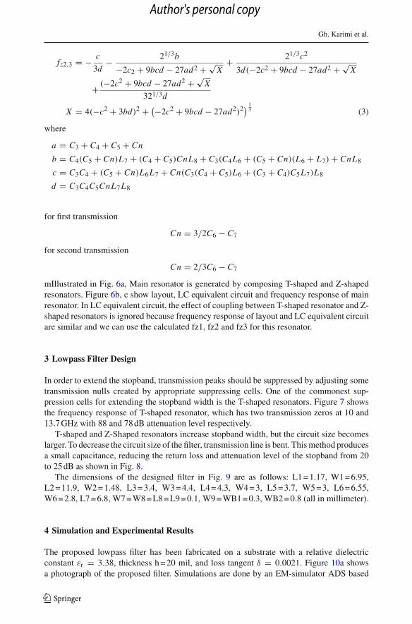
fz2,3 = − c
3d− 21/3b
−2c2 + 9bcd − 27ad2 + √X
+ 21/3c2
3d(−2c2 + 9bcd − 27ad2 + √X
+ (−2c2 + 9bcd − 27ad2 + √X
321/3d
X = 4(−c2 + 3bd)2 + (−2c2 + 9bcd − 27ad2)2) 13 (3)
where
a = C3 + C4 + C5 + Cn
b = C4(C5 + Cn)L7 + (C4 + C5)CnL8 + C3(C4 L6 + (C5 + Cn)(L6 + L7) + CnL8
c = C3C4 + (C5 + Cn)L6L7 + Cn(C3(C4 + C5)L6 + (C3 + C4)C5L7)L8
d = C3C4C5CnL7L8
for first transmission
Cn = 3/2C6 − C7
for second transmission
Cn = 2/3C6 − C7
mIllustrated in Fig. 6a, Main resonator is generated by composing T-shaped and Z-shapedresonators. Figure 6b, c show layout, LC equivalent circuit and frequency response of mainresonator. In LC equivalent circuit, the effect of coupling between T-shaped resonator and Z-shaped resonators is ignored because frequency response of layout and LC equivalent circuitare similar and we can use the calculated fz1, fz2 and fz3 for this resonator.
3 Lowpass Filter Design
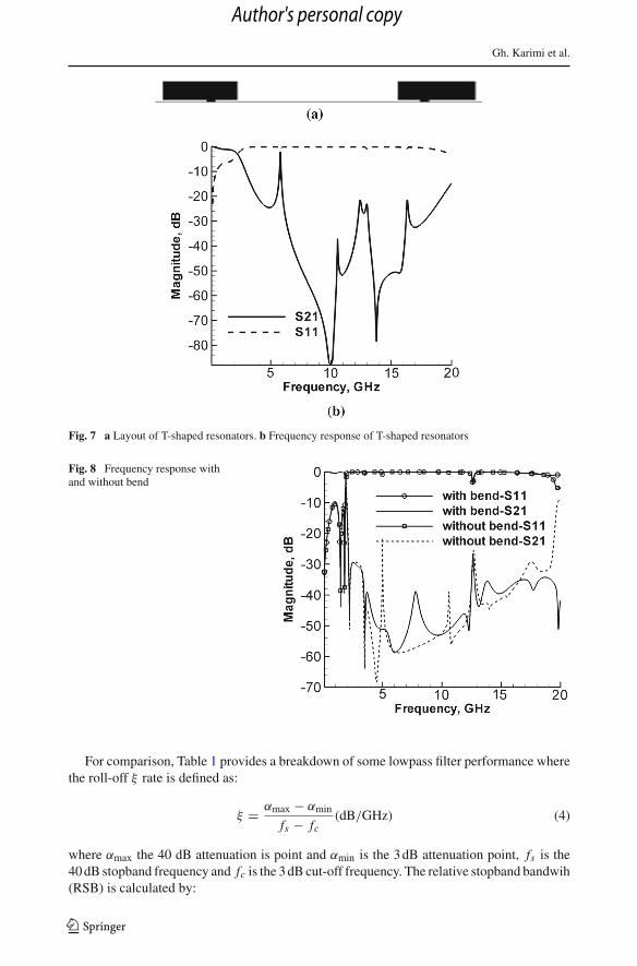
In order to extend the stopband, transmission peaks should be suppressed by adjusting sometransmission nulls created by appropriate suppressing cells. One of the commonest sup-pression cells for extending the stopband width is the T-shaped resonators. Figure 7 showsthe frequency response of T-shaped resonator, which has two transmission zeros at 10 and13.7 GHz with 88 and 78 dB attenuation level respectively.
T-shaped and Z-Shaped resonators increase stopband width, but the circuit size becomeslarger. To decrease the circuit size of the filter, transmission line is bent. This method producesa small capacitance, reducing the return loss and attenuation level of the stopband from 20to 25 dB as shown in Fig. 8.
The dimensions of the designed filter in Fig. 9 are as follows: L1 = 1.17, W1 = 6.95,L2 = 11.9, W2 = 1.48, L3 = 3.4, W3 = 4.4, L4 = 4.3, W4 = 3, L5 = 3.7, W5 = 3, L6 = 6.55,W6 = 2.8, L7 = 6.8, W7 = W8 = L8 = L9 = 0.1, W9 = WB1 = 0.3, WB2 = 0.8 (all in millimeter).
4 Simulation and Experimental Results
The proposed lowpass filter has been fabricated on a substrate with a relative dielectricconstant εr = 3.38, thickness h = 20 mil, and loss tangent δ = 0.0021. Figure 10a showsa photograph of the proposed filter. Simulations are done by an EM-simulator ADS based
123
Author's personal copy

Design of Modified Z-Shaped and T-Shaped Microstrip Filter
Fig. 6 a Layout of the proposedresonator, b L–C equivalentcircuit, c EM and circuitsimulation results of mainresonator
on the method of moment. The S-parameters are measured by an Agilent network analyzerN5230A. Simulated and measured responses of the filter are shown in Fig. 10b. It can beseen from the results that the filter has 3 dB cutoff frequency equal to 1.89 GHz, insertionloss less than 1.8 dB in the passband from DC to 0.5 GHz, return loss better than −10.3 dBand suppression level better than −25 dB from 2.01 up to 20 GHz. The size of the lowpassfilter is only 19.9 × 8.5 mm and the transition band from 1.89 to 2.05 GHz with −3 and−20 dB.
123
Author's personal copy
Gh. Karimi et al.
Fig. 7 a Layout of T-shaped resonators. b Frequency response of T-shaped resonators
Fig. 8 Frequency response withand without bend
For comparison, Table 1 provides a breakdown of some lowpass filter performance wherethe roll-off ξ rate is defined as:
ξ = αmax − αmin
fs − fc(dB/GHz) (4)
where αmax the 40 dB attenuation is point and αmin is the 3 dB attenuation point, fs is the40 dB stopband frequency and fc is the 3 dB cut-off frequency. The relative stopband bandwih(RSB) is calculated by:
123
Author's personal copy

Design of Modified Z-Shaped and T-Shaped Microstrip Filter
Fig. 9 Layout of the proposedfilter
Fig. 10 a Photograph of theproposed filter. b Simulated andmeasured performance oflowpass filter
RSB = stopband bandwidth
stopband center frequency(5)
The suppression factor (SF) is based on the stop-band bandwidth. For example, the stop-band bandwidth is referred to 25 dB suppression, thus the corresponding SF is defined as2.5. A higher suppression corresponds to a greater SF. The normalized circuit size (NCS) iscalculated by:
123
Author's personal copy

Gh. Karimi et al.
Table 3 Performance comparison among published filters and presented one
References Roll-off RSB SF NCS AF FOM
Krishna Velidi and Sanyal [2] 95 1.4 2 0.214 × 0.104 1 11,951
Karimi et al. [3] 202 1.65 2 0.29 × 0.124 1 19,951
Ma and Yeo [4] 94.9 1.6 2.3 0.104 × 0.123 1 27,292
Wang et al. [5] 36 1.32 1.5 0.079 × 0.079 1 11,543
Hayati et al. [6] 62 1.72 3 0.310 × 0.240 1 4,430This work 137 1.69 2.5 0.204 × .0.087 1 32, 613
NCS = physical size (length × width)
λ2g
(6)
where λg is the guided wavelength at 3 dB cutoff frequency. The architecture factor (AF) canbe recognized as the circuit complexity factor, which is equal to 1 when the design is 2D andit is equal to 2 when the design is 3D. Finally, the figure-of-merit (FOM), the overall indexof a proposed filter, is given by:
FOM = ξ × RSB × SF
NC S × AF(7)
As seen from this table, the proposed filter offers good performance, compact size, ultra-wide stopband and outstanding electrical performance among the quoted filters, being moresuitable for using in modern UWB systems (Table 3).
5 Conclusion
A lowpass filter with 1.89 GHz cut-off frequency using the modified T-shaped resonator hasbeen designed, fabricated and measured. The proposed lowpass filter has exhibited manydesirable features, such as ultra-wide stopband, sharp characteristic and compact size. Thispaper has presented a novel analytical method based on calculated and examined transmissionzero and transformation function of the main resonator. With all these good features, theproposed filter is applicable for modern communication systems.
References
1. Hong, J. S., & Lancaster, M. J. (2001). Microstrip filters for RF/microwave applications. New York:Wiley.
2. Krishna Velidi, V., & Sanyal, S. (2011). Sharp roll-off lowpass filter with wide stopband using stub-loadedcoupled-line hairpin unit. IEEE Microwave and Wireless Components Letters, 21(6), 301–303.
3. Karimi, G., Lalbakhsh, A., & Siahkamari, H. (2013). Design of sharp roll-off lowpass filter with ultra widestopband. IEEE Microwave and Wireless Components Letters, 23(6), 303–305.
4. Ma, K., & Yeo, K. S. (2011). New ultra-wide stopband low-pass filter using transformed radial stubs. IEEETransactions on Microwave Theory and Techniques, 59(3), 604–611.
5. Wang, J., Xu, L.-J., Zhao, S., Guo, Y.-X., & Wu, W. (2010). Compact quasi-elliptic microstrip lowpassfilter with wide stopband. IEE Electronics Letters, 46(20), 1384–1385.
6. Hayati, M., Asadbeigi, H., & Sheikhi, A. (2012). Microstrip lowpass filter with high and wide rejectionband. Electronics Letters, 48(19), 1217–1219.
7. Hayati, M., & Sheikhi, A. (2011). Microstrip lowpass filter with very sharp transition band and widestopband. ETRI Journal, 33(6), 981–984.
8. Krishna Velidi, V., KantiMandal, M., & Sanyal, S. (2009). Compact lowpass filters, microstrip coupled-linelowpass filter with wide stopband for RF/wireless systems. ETRI Journal, 31(3), 324–326.
123
Author's personal copy

Design of Modified Z-Shaped and T-Shaped Microstrip Filter
Gh. Karimi was born in Kermanshah, Iran in 1977. He receivedthe B.S. and M.S. and PhD degrees in electrical engineering fromIran University of Science and Technology (IUST) in 1999, 2001 and2006 respectively. He is currently an Assistant Professor in ElectricalDepartment at Razi University, Kermanshah, since 2007. His researchinterests include low power Analog and Digital IC design, RF ICdesign, modeling and simulation of RF mixed signal IC and microwavedevices.
H. Siahkamari was born in Kermanshah, Iran in 1988. He received hisB.Sc. degree in Electronic Eng. in 2010 from Islamic Azad University,Kermanshah Branch, Kermanshah, Iran and he is now an M.Sc colle-gian in Electronic Eng. in Razi University, Kermanshah, Iran. His cur-rent research interests are RF/Microwave circuit design.
F. Khamin Hamedani was born in Kermanshah, Iran in 1980. Shereceived her B.Sc. degree in Electronic Eng. in 2003 from Razi Univer-sity, Kermanshah, Iran and she is now an M.Sc collegian in ElectronicEng. in Islamic Azad University, Science and Research Branch, Ker-manshah, Iran. Her current research interests are RF/Microwave circuitdesign.
123
Author's personal copy
Gh. Karimi et al.
A. Lalbakhsh was born in Tehran, Iran in 1985. He received the B.Sc.and M.Sc. degrees in Communication Engineering from the IslamicAzad University, Boroujerd Branch, in 2008 and Islamic Azad Univer-sity, Science and Research Branch in 2011, respectively. From 2010 hehas been lecturing at Islamic Azad University, Kermanshah Branch. Hisresearch interests include Microwave passive components, Microstripantenna and RF circuit design. Lalbakhsh is a member of IEEE andIEICE from 2011. He has also served as a reviewer for several journals.
123
Author's personal copy