Double semiconductor substrate in overlay shielded superconducting microstrip lines
12
International Journal of Infrared and Millimeter Waves. Vol. 1Z No. 8, 1996 DOUBLE SEMICONDUCTOR SUBSTRATE IN OVERLAY SHIELDED SUPERCONDUCTING MICROSTRIP LINES Humberto C6sar Chaves Fernandes and. Idalmir de Souza Queiroz Jfinior Department of Electrical Engineering-Technological Center Federal University of Rio Grande do Norte P.O.Box 1583 59.072-970-Natal-RN, Brazil Tel~Fax: +55 84 231.4254 e-mail: [email protected] Received June 4, 1996 ABSTRACT The Transverse Transmission Line (TTL) is used in the theory of the overlay shielded microstrip lines considering the superconductor strip on two semiconductor regions. The superconductor effect is included with the boundary condition of the surface impedance, that is related to the complex conductivity of the material, calculated fi'om the advanced two-fluid model. Applying the moment method the complex propagation constant of the structure, including the phase constant and the attenuation constant, is obtained. Results are presented for the complex propagation constant, versus the frequency and the temperature, of this overlay superconducting microstrip lines. Key words: Superconductor, Microstrip, Semiconductor, TTL Method. 1. Introduction The microstrip line is a structure normally utilized in Microwave Monolithic Integrated Circuits --MMIC's. The utilization of high-Tc 1391 0195-927|/96/0800-139l$09.50/0 © 1996 Plenum Publishing Corporation
-
Upload
independent -
Category
Documents
-
view
1 -
download
0
Transcript of Double semiconductor substrate in overlay shielded superconducting microstrip lines
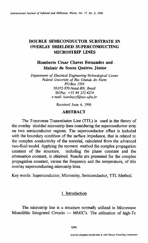
International Journal of Infrared and Millimeter Waves. Vol. 1Z No. 8, 1996
DOUBLE SEMICONDUCTOR SUBSTRATE IN OVERLAY SHIELDED SUPERCONDUCTING
MICROSTRIP LINES
Humberto C6sar Chaves Fernandes and. Idalmir de Souza Queiroz Jfinior
Department o f Electrical Engineering-Technological Center Federal University o f Rio Grande do Norte
P.O.Box 1583 59.072-970-Natal-RN, Brazil
Tel~Fax: +55 84 231.4254 e-mail: [email protected]
Received June 4, 1996
ABSTRACT
The Transverse Transmission Line (TTL) is used in the theory of the overlay shielded microstrip lines considering the superconductor strip on two semiconductor regions. The superconductor effect is included with the boundary condition of the surface impedance, that is related to the complex conductivity of the material, calculated fi'om the advanced two-fluid model. Applying the moment method the complex propagation constant of the structure, including the phase constant and the attenuation constant, is obtained. Results are presented for the complex propagation constant, versus the frequency and the temperature, of this overlay superconducting microstrip lines.
Key words: Superconductor, Microstrip, Semiconductor, TTL Method.
1. Introduction
The microstrip line is a structure normally utilized in Microwave Monolithic Integrated Circuits - -MMIC's . The utilization of high-Tc
1391
0195-927|/96/0800-139l$09.50/0 © 1996 Plenum Publishing Corporation

1392 Fernandes and Queiroz J6nior
superconductor films in the structures has practical applications [1] and permit a reduction of ohmic losses and low dispersion.
Different methods have been proposed in the Fourier transform domain ( FTD ) and others schemes [2]-[10], for the microstrip and stripline characterization. In this work is used the full wave analysis of the Transverse Transmission Line ( TTL ) method, developed by the authors recently with success [2],[8]-[10]. This TTL method permits an exact and concise analysis to obtain the dyadic Green matrix impedance.
For microstrip with the superconductor film thickness, tsc , much
thinner than the effective penetration depth, ~eff, the introduction of this
superconductor can be analyzed by considering a Complex Resistive Boundary Condition [4]. The conductivity of the superconductor film is complex and is given by the Two Fluid Theory[4].
This full wave TTL analysis in the spectral domain [2], is used in the theory of the overlay shielded microstrip lines considering the superconductor strip on two semiconductor regions, shown in the Fig. 1.
I< db ~t
Fig. 1. Cross section of the overlay shielded superconducting microstrip line on double substrate with losses.

Superconducting Microstrip Lines 1393
Therefore two type of losses can be present in this structure: one is caused by the superconducting line and another one is caused by the complex substrate.
The superconductor effect is included with the boundary condition of the surface impedance, that is related to the complex conductivity of the material, calculated from a advanced two-fluid model [2],[4]. In the TTL method the electromagnetic fields in directions ~ and ~. (~. is the direction of propagation with complex constant F=cz+jl 3) are obtained as functions of the transverse electromagnetic fields. Applying the magnetic boundary condition with the surface impedance, is obtained a matrix system that relates the tangential electric fields with the surface current densities resulting the impedance matrix.
In the sequence, the moment method is used conducing to a characteristic equation, such that their roots are numerically calculated to given the complex propagation constant, including the phase constant and the attenuation constant. Results are presented for the phase constant and attenuation constant as a function of the temperature and of the frequency, for the superconductor microstrip on complex substrate, where the effects of the high-Tc superconductor are showed.
2. Theory_
In the TTL method, applying the Maxwell equations, a set of equations that represent the electromagnetic fields, in the direction ~ and £, in the regions of the structure are given as a function of the fields in the direction ~, transverse to the interfaces, in the Fourier transform domain (FTD), as follow:
1 I - a t . / x- -I
or,
( 1 )
(2)

1394 Fernandes and Queiroz Jfnior
- J a, Uor~ +a J ( 3 ) ~ x ~ - k i ~ + r ~ '~ °
' I zi = -- 2 8 y k i + y ? (0 f l00~nHy i + F E y i ( 4 )
xi - k 2 -- ' i yi 8 y i +r~ o ~ r E - a . y~ ( 5 )
,[ 8] z," = k~ + 7 ' ? < a z i a n E ' y i - F 8 y H y i
where, k i is the wave number, 3'i is the propagation constant in y
direction, F = a + j13 is the propagation constant, a n is the spectral
variable, and i = 1, 2, 3 and 4 are the considered regions.
Applying the boundary conditions and the Helmholtz equations, the electromagnetic fields of the microstrip line are obtained. y=0: E,, = F'z, = 0 (7.1)
y-=s" F,,, = Ex2, Ez, = E,z, B[x, = B[,2, Hxl = H,2 (7.2)
V =h" E,z = E z~, E22 = E, , , F',3 = F-',g, F-'23 = E,, (7.3)
Y=2.a E , 3 = Eza = 0 (7.4)
As an example at the region (1) this field is:
where,
A = sinh(y,s) cosh(v 2g) + "[1 cosh(T,s)sinh(T 2g) (8. I) V2

Superconducting Microstrip Lines
B = ~' lsinh(y is)cosh(y 2g) + 3'2 et cosh(y ls)sinh(3 ' 2g) G2
1395
(8.2)
After application of the magnetic boundary conditions the matrix equation is obtained relating the fields and the current densities,
( 9 )
where [2] represent the dyadic Green impedance matrix in the FTD,
obtained by the TTL method. After to obtain this matrix, the Complex Resistive Boundary
Conditions model [2;4] is applied to include the superconducting characteristic of the microstrip structure. The tangential components of the electric field on the plane y =g (h~ +h2) are given as
= Ex~ + Exg ~ in ~ o E~ E~ +E~
(10 )
~O ~O where E~ and E~ are the electric fields out of the superconductor, and, - in ~in Ex~ and E~ are the electric fields in the superconductor. These last fields
are related with the current densities by the presence of the impedance surface, since the superconducting film thickness is much thinner than ~, eft [2], [4]. This impedance surface is given as
1 zs - (11)
t ,%c
where Crsc is the conductivity of the superconductor and is obtained of the Two Fluid theory [4]:
ITI 4 .(11 (12 )

1396 Fernandes and Queiroz Jtinior
gn is the conductivity of the superconductor, T c is the critical
temperature of the superconductor, and, 7~eff (0) is the penetration
effective depth when T = 0 K. The Two Fluid theory is used for high- temperature materials with success at the present time, appears of the originally applied in low-temperature materials[4]. The "enhanced" Two Fluid theory is used by others authors for corrections in materials parameters obtaineA experimentally [7].
After the inclusion of the superconducting impedance, considering the algebraic modifications, the matrix equation ( 9 ) is changed for:
7-'zx ( 1 3 )
where [J] is the surface current density in the superconductor strip, [E] is the tangential electrical field in the lateral of the superconducting strip, and [Z] is the impedance matrix.
The Moment method is applied at the equation (13), resulting in the matrix equation. (14),
(14)
In this matrix the surface current densities was expanded in terms of basis functions, where [ a ] are the unknown coefficient of these functions. The complex root of the determinant of [K] is the complex propagation constant, F = ot + j13, where ot is the attenuation constant and 13 is the phase constant.

Superconducting Microstrip Lines 1397
3. Results
Using a Pentium, 100 MHz microcomputer, a program in the FORTRAN 77 language was developed to calculate the complex propagation constant of the shielded overlay superconducting microstrip line including two substrates with losses. The numerical results are presented for the effective dielectric constant and attenuation constant as a function of the frequency to various temperatures and conductivity. In all figures the superconducting material used is the (YBCO), where the effective penetration depth at temperature of 0 K is ~ 0 ) = 150 nm, the conductivity at normal temperature (T > Tc) is o,=2x10⁵ S/m and the critical temperature Tc = 90 K.
In the Fig. 2.a results of the effective dielectric constant as a function of the strip width are presented for various temperature, and different conductivities. In the Fig. 2.b the results of the attenuation constant are presented for the same parameters as in Fig.2.a. Regions 1 and 2 are identical for these results.

1398 Fernandes and Queiroz Jt~nior
17
en ' r
16
15
14
13
12
11
10:'
c t ( d B / m
10 =
101
%
+ i i + i t
Crl = 1.0 8,~n
f= 1.0 Gila
. \ / / hl=h ~01 t 211ml
Sr~ 12.9
~ = 0 S / m ~ . g K . f . ~ ~., ,= =_--~ .~+r-
T~70K % +_,. -~', , o.2 o.4 o16 & o:7 o18 o19
w (ram)
(a)
a I = 1,0 ~/m
f = I.O GHz h l = h =03
t= llam
a I ~ 0.I S/m
-. . . . . . . . . . . . . . . . . . . . . . . . ,--,-
8f~ 12.9
8r~ ].?S
tJ3 = 0 ~ m ¢~1 = o.01 $hn
T= 89.9 I~ T=?OK - -
o12 o13 o14 o15 o16 o17 o18 o19 w ( m m )
(b) Fig. 2. Results o f the a) effective dielectric constant and b) attenuation
constant, as a function of the strip width of the shielded overlay superconducting microstrip line on semiconductor substrate.
In the fig. (3)-(4) are used a WR-28 (da = 7.112 mm, db = 3.556 mm), s=0.154mm, g= 0.1 mm, r = 10.0 nm and wl = 0.4 m m the substrates used are the RT-duroid 5880 TM where e, = 2.22, and the e~.=10.5 to substrate with losses, the temperature used is T=70 K.

S u p e r c o n d u c t i n g M i c r o s t r i p L i n e s 1 3 9 9
4.5
Serf
4.0
3.5
3.0
2.5
2.0
1.5 O.
120.
~(Np/m
100.
80.
60.
40.
20.
O. O.
d a = 7 . 1 1 2 m m
d b = 3 . 5 5 6 m m
sn = 2.22
o l = , ~ = 0 . 0 S / m a e = 10.5
~ . . ,~ = , ~ = 0 . 5 S / m a-z = 1.0 = 0.0 S/m
c~ = o~ = 1.0 Slm
,.~t = aa = 2.22 This W o r k r.s = 1.0
~x R e f . [ l ] o~ = o 2 = o3 = 0 .0 S / m
-- , , . . . . . X X ;~ ^ -- ^ ~ A A n
,io. l'oo. Frequency(GHz)
(a)
f Srl = 2.22
s~ = I0,5
sa = 1.0
03 = 0,0 Slm mr- 01 = o= = 0.0 S/m (Ref.[l] and This Work)
eeo t= oz= 0.5 S/m - - O t = oz= 1 .0 Slm ( ~ . . _ . . . e _ ~ o o O 0 O o o
d a = 7 . 1 1 2 m m
d b = 3.556 r a m
s a = s a = 2 . 2 2
c ~ = 1 . 0
c 3 = 0 . 0 S / m
^ 2 0 . ~ 4"0. ^ 6 0 . ~ 8 0 . ^ 1 0 0 .
Frequency (GHz)
(b) Fig. 3. Effect of conductivity of the substrate on the propagation
constant, m: (a) effective dielectric constant, and (b) attenuation constant, versus frequency of the shielded microstrip line with two layers substr~ t~

1400 Fernandes and Queiroz Jdnior
9.0
E:eff
8.0
7.0
6.C
5.0
4.0
3.0 O.
¢t~ = 2.22 , d ~ rt2 = 10.5
~3 = 1.0 ~ / X T = ol =02 = m =0.0 S/m - - T = 1(10 K da=7.112mm ooT=80K"
• ~ a=r-T= gB
do. 1'oo. Frequency(GHz)
(a)
200.
[ ~-2 = 10.5 /
160. / r¢3 = 1.0 / al =o'2 ~o-~ =0.0S/m . /
140. da = 7.112 rran I t
120. db = 3.556 mm
/ 100.
80.
- - T = 10 K ~ / 60. ooT= g0K . /
40. -~-T= 88 X / F
o. - ~ ~ ~ ~ ~'o " ~'o - f o o .
Frequency(GHz)
(b) Fig.4. Temperature of the superconductor, to: (a) effective dielectric
constant, and (b) attenuation constant, versus frequency of the shielded microstrip line with two layers.

Superconducting Microstrip Lines 1401
4. Conclusions
The utilization of superconducting film in microwave devices, as microstrip, open a variety of new applications. The advantages include low attenuation, low distortion and the propagation of slow waves. The comparisons realized shows this advantages. The inclusion of the semiconductor substrate with the complex variables, permit the use of these superconducting microstrip line in solid state devices.
A new conjunction of methods are utilized for the characterization of these structures that use high-Tc superconducting : the TTL - - Transverse Transmission Line, and the Complex Resistive Boundary Condition model. The analysis have been concise and objective, producing excellent results, that were compared with that obtained in another works.
This work was supported by CNPq and CAPES.
References
1. S. M. El-ghazaly, R. B. Hammond e T. Itoh, "Analysis of Superconducting Microwave Structures: Application to Microstrip Lines", IEEE Trans. Theory and Tech., vol. 40, n -° 03, pp. 499-508, march (1992).
2. H.C.C.Femandes, "Shielded and Open Two-layer Superconducting Microstrip Lines", SPIE's 1995 International Symposium on Optical Science, Engineering and Instrumentation, in the Conference, High- Temperature Microwave Superconductors and Applications, San Diego, CA, USA, Conf. Proc. pp. 22-29, Jul. (1995).
3. J.M.Schellenberg, "CAD Models for Suspended and Inverted Microstrip", IF~EE Trans. Microwave Theory and Techniques, vol. 43, n -° 6, pp. 1247-1252, June, (1995).
4. J.M.Pond, C.M.Crowne and W.L.Carter, "On the Application of Complex Resistive Boundary Conditions to Model Transmission Lines Consisting of Very Thin Superconductors", IEEE Trans. on
M77"., vol. 37, n- ° 1, pp. 181-190, Jan. (1989). 5. Z. Cai e J. Bomemann, "Generalized Spectral Domain Analysis for
Multilayred Complex Media and High-Tc Superconductor

1402 Fernandes and Queiroz J•nior
Applications", IEEE Trans. Theory and Tech., vol. 40, n -° 12, pp. 2251-2257, Dec. (1992).
6. D. Nghiem, J. T. Willians e D. R. Jackson, "A General Analysis of Propagation along Multiple-Layer Superconducting Stripline and Microstrip Transmission Lines", IEEE Trans. Theory and Tech., vol. 39, n -° 9, pp. 1553-1565, Sept. (1991).
7. O. R. Baiocchi, K. Kong and T. Itoh, "Pulse Propagation in Superconducting Coplanar Striplines", IEEE Trans. Theory and Tech., vol. 40, n -° 03, pp. 509-513, March (1992).
8. H.C.C. Femandes, A. C. R. de Brito, R. S. de Oliveira e A. M. B. Jfinior, "Attenuation and phase in microstrip lines with one and two different semiconductor substrates", ( in Portuguese ), 11 -° Brazilian Telecommunications Symposium, Natal-RN/Brazil, Conf. Proc., pp. 581-585, Sept. (1993).
9. H. C. C. Femandes, E. A. M. Souza, E. D. Barbosa e N. D. de Freitas, "Characterization of Unilateral Finlines Considering the Conductor Thickness", 17 ~ International Conference on Infrared and Millimeter Waves, Proc. pp. 496-499, Pasadena-CA USA, Dec. (1992).
10. H.C.C.Femandes, E.A.M.Souza e I.S.Queiroz Jr., "High precision analysis offinlines on semiconductor substrate", International Journal of Infrared and Millimeter Waves, Vol. 16, N ° 1 pp.185-200, Jan. (1995).