A RECONFIGURABLE CEDAR-SHAPED MICROSTRIP ANTENNA FOR WIRELESS APPLICATIONS
13
Progress In Electromagnetics Research C, Vol. 25, 209–221, 2012 A RECONFIGURABLE CEDAR-SHAPED MICROSTRIP ANTENNA FOR WIRELESS APPLICATIONS M. A. Madi, M. Al-Husseini * , A. H. Ramadan, K. Y. Kabalan, and A. El-Hajj ECE Department, American University of Beirut, P. O. Box 11-0236, Bliss Street, Beirut 1107 2020, Lebanon Abstract—This paper presents a frequency reconfigurable cedar- shaped fractal antenna. The special shape of the patch makes it simpler to integrate RF switches to connect consecutive branches. The proper activation/deactivation of the switches alters the current flow and changes the resonance frequency. Simulated and measured results show the characteristics of the presented design. 1. INTRODUCTION Research in electromagnetism and antenna design has focused on improving the antenna characteristics to fit modern telecommunica- tions demands for miniaturized antennas that operate over multiple bands [1]. The tendency of grouping many services in an increasingly narrow space has made fractal antenna design a research hotspot. On the other hand, maintaining acceptable radiation pattern and gain characteristics, and improving noise mitigation, has led to focus on reconfigurability techniques. Fractal theory, proposed by B. Mandelbrot, states that the space can have a fractional dimension that is in contrast with Euclidean space [2]. Fractal geometry is based on self repetition leading to infinitely fine structures thus simulating natural elements [2]. The space-filling property results in miniaturizing classic antenna elements. Another characteristic of fractal shapes is the self-similarity property employed to maintain antenna characteristics [3,4]. Fractals can best be generated by iterating a certain shape with an increasingly reduced scale for consecutive iterations. As a result, the electrical length of the antenna increases causing the resonant frequency to be lowered achieving physical reduction of the antenna. Received 12 October 2011, Accepted 17 November 2011, Scheduled 24 November 2011 * Corresponding author: Mohammed Al-Husseini ([email protected]).
-
Upload
independent -
Category
Documents
-
view
0 -
download
0
Transcript of A RECONFIGURABLE CEDAR-SHAPED MICROSTRIP ANTENNA FOR WIRELESS APPLICATIONS
Progress In Electromagnetics Research C, Vol. 25, 209–221, 2012
A RECONFIGURABLE CEDAR-SHAPED MICROSTRIPANTENNA FOR WIRELESS APPLICATIONS
M. A. Madi, M. Al-Husseini *, A. H. Ramadan,K. Y. Kabalan, and A. El-Hajj
ECE Department, American University of Beirut, P. O. Box 11-0236,Bliss Street, Beirut 1107 2020, Lebanon
Abstract—This paper presents a frequency reconfigurable cedar-shaped fractal antenna. The special shape of the patch makes itsimpler to integrate RF switches to connect consecutive branches. Theproper activation/deactivation of the switches alters the current flowand changes the resonance frequency. Simulated and measured resultsshow the characteristics of the presented design.
1. INTRODUCTION
Research in electromagnetism and antenna design has focused onimproving the antenna characteristics to fit modern telecommunica-tions demands for miniaturized antennas that operate over multiplebands [1]. The tendency of grouping many services in an increasinglynarrow space has made fractal antenna design a research hotspot. Onthe other hand, maintaining acceptable radiation pattern and gaincharacteristics, and improving noise mitigation, has led to focus onreconfigurability techniques.
Fractal theory, proposed by B. Mandelbrot, states that the spacecan have a fractional dimension that is in contrast with Euclideanspace [2]. Fractal geometry is based on self repetition leading toinfinitely fine structures thus simulating natural elements [2]. Thespace-filling property results in miniaturizing classic antenna elements.Another characteristic of fractal shapes is the self-similarity propertyemployed to maintain antenna characteristics [3, 4]. Fractals can bestbe generated by iterating a certain shape with an increasingly reducedscale for consecutive iterations. As a result, the electrical length ofthe antenna increases causing the resonant frequency to be loweredachieving physical reduction of the antenna.
Received 12 October 2011, Accepted 17 November 2011, Scheduled 24 November 2011* Corresponding author: Mohammed Al-Husseini ([email protected]).

210 Madi et al.
Various fractal shapes have been implemented to design compact-sized antennas. In a nested triangle [2], the height and angle ofthe largest triangle and the number of nested triangles are varied toobtain the desired pass-band characteristics of the antenna. Koch-based fractal is exploited with two iterations in [5] to achieve a goodaxial ratio, where as in [6], a second-iterated Sierpinski carpet is usedto obtain ultra wide band operation. In [4], natural structures with oneor more iterations have been used to show the efficiency of using fractalshapes in designing antennas that respond to telecommunicationsystem developments and the need for portable devices.
Grouping many services in one antenna, using the reconfigurabilityapproach, results in better isolation of antennas and hence, increasesthe efficiency of modern platforms. In particular, due to theirimproved out of band rejection, frequency reconfigurable antennassurpass multiband antennas as they do not necessitate highly efficientnoise filters and thus the cost of the overall antenna is reduced [1].Employing frequency reconfigurable antennas also preserves theradiation properties at the various reconfigured frequencies. Frequencyreconfigurability is usually achieved by incorporating switches acrossslots such as MEMS switches and p-i-n diodes. In [7], the authorspresent a PCB with electronic switches placed across slots in the feedline for Cognitive Radio applications. Optical switching was also usedin [8] to obtain frequency reconfigurability where laser diodes wereembedded in the substrate.
In general, the switches use de-biased signals to change the currentpath and to shorten the electrical length of the antenna [1]. Switchescould be used to vary the depth of slots [9] which varies the electricallength of the antenna and consequently its resonant frequency. Theymay also be used to control the current flow path within two differentconfigurations printed on the same patch, such as an inner and an outersquare patch [10]. Compared to p-i-n diodes, RF MEMS switchesconsume less power and perform better but are still costly, so whenused they are subject to optimization in positioning and quantity.Compared to p-i-n diodes, RF MEMS switches consume less powerand perform better but are still costly, so when used they are subjectto optimization in positioning and quantity [1]. Some configurationsare adapted to host electronic switches due to their richness. A Vivaldiantenna is used by the authors in [11] to incorporate four pairs of p-i-ndiodes. A dual frequency reconfigurable TLLPD (tunable loop-loadedprinted dipole) is reported in [12]. The authors in [13] present anantenna with band notch reconfigurability based on complementarysplit-ring resonators (CSRRs) and split-ring resonators (SRRs).
Designing a fractal antenna in combination with reconfigurability

Progress In Electromagnetics Research C, Vol. 25, 2012 211
approach that incorporates electronic switches has produced moreefficient antennas with size reduction. The authors of [14] apply aKoch curve to a U-slotted square patch to obtain wide band frequencyreconfigurability. In [15], the authors use Sierpinski triangles to builda fractal Gasket-shaped frequency reconfigurable antenna.
This paper adopts a cedar-shaped microstrip antenna which ischaracterized by its fractal geometry that allows for a wide range ofpossibilities for placing RF switches. The antenna design is based onhaving pairs of symmetrical slots to form branches. Switches mountedover these slots could be activated to obtain frequency reconfigurability.The space filling property and self similarity of the fractal shape haveserved to decrease the antenna’s operation frequencies and to keep theconsistency of its radiation patterns, respectively.
2. ANTENNA DESIGN
An equilateral patch antenna is first designed to resonate at 2.4GHz.The relation between the dimension of an equilateral triangle patchand the resonant frequency is given in Equation (1) [16]. A side lengthof 38.86 mm (height = 33.65mm) is obtained.
fmnl =2c
3a(εr)1/2
(m2 + mn + n2
)1/2 (1)
Figure 1. Antenna geometry (dimensions in mm).

212 Madi et al.
In (1), c is the velocity of electromagnetic waves in free space, εr
is the dielectric constant of the substrate, m, n, and l are the integerscorresponding to the mode, and a is the side length of the equilateraltriangle.
Trims are to be symmetrically incorporated into the triangularpatch to form the branches of the cedar. To give more area tothese trims, and to keep the matching at around 2.4 GHz, the baseof the patch (side connected to the feed line) has to be elongated,and the height has to be shortened. For three trims on each side, theoptimizations lead to a base length and a height of 49 mm and 31.5mm,respectively.
Further optimizations are done to ensure positive gain and alsofor aesthetic reasons. The final design, which now has the shape ofa cedar tree, is printed on an FR4-epoxy substrate with a dielectricconstant εr = 4.4, and has a full ground plane, and a 50-Ω matchedmicrostrip feed line. Three pairs of switches are mounted across thetrims to control the current flow on the patch. The detailed antennais described in Figure 1.
A parametric study for the positions of the switches is done, anda prototype based on selected locations of the switches is fabricated,as demonstrated in the next section.
Figure 2. S11 results for variable positions of (S1, S′1) with (S2, S′2)and (S3, S′3) in the OFF state.
Progress In Electromagnetics Research C, Vol. 25, 2012 213
3. RESULTS AND DISCUSSION
The design and parameter optimization are done using AnsoftHFSS [17], which is based on the Finite-Element Method (FEM). Themeasurements are done using Agilent’s E5071B network analyzer.
Since the positions of the switches affect the current flowpath, varying these positions certainly tunes the obtained resonancefrequency. The positions of the switches are denoted d1, d2, and d3, asshown in Figure 1, and a parametric study is done to show the effectof a switch position of the antenna’s resonance.
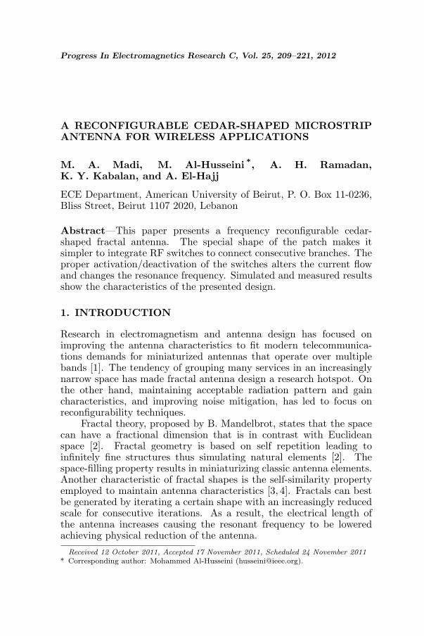
Figure 3. S11 results for variable positions of (S2, S′2) with (S1, S′1)in the ON state at d1 = 2.26mm and (S3, S′3) in the OFF state.
Figure 4. S11 results for variable positions of (S3, S′3) with (S1, S′1)and (S2, S′2) in the ON state at d1 = 2.26mm and d2 = 2.13mm.

214 Madi et al.
First, switches (S1, S′1) are turned ON and switches (S2, S′2) and(S3, S′3) are turned OFF. Then switches (S1, S′1) are placed at severalpositions, and the corresponding resonance frequency is obtained. Thereflection coefficient plots for 6 different d1 values are given in Figure 2.They show that the resonance frequency increases with decreasing d1
value.Fixing the positions of (S1, S′1) at d1 = 2.26mm, (S2, S′2) are
moved over 5 different positions achieving frequency tunability in
Table 1. Switch states for Cases 0, 1, 2, and 3.
Case (S1, S′1) (S2, S′2) (S3, S′3)Resonance Frequency
(GHz)Gain (dB)
0 OFF OFF OFF 2.075 0.2798
1 ON OFF OFF 2.145 1.0373
2 ON ON OFF 2.295 2.1824
3 ON ON ON 2.325 2.5098
Figure 5. Current distribution for switching Cases 0, 1, 2, and 3presented in Table 1.

Progress In Electromagnetics Research C, Vol. 25, 2012 215
2.235–2.305GHz frequency band as shown in Figure 3. The resonancefrequency increases with decreasing d2 value.
Similarly, the positions of the first two pairs of switches are fixedat d1 = 2.26mm and d2 = 2.13mm while (S3, S′3) are moved in 5switching cases to tune the antenna in 2.305–2.335 GHz band as shownin Figure 4.
The locations of the switches are chosen such as d1 = 2.26mm,d2 = 2.13mm and d3 = 0.385mm (refer to Figure 1). The successiveactivation of each pair of switches, from bottom to top, results inaltering the flow of current and as a result in shifting the resonancefrequency. Four switching cases are chosen, as listed in Table 1. Thecurrent distribution on the patch for these cases is shown in Figure 5.When a switch is OFF, the current flows around the correspondingtrim, thus its path is longer, and the resonance frequency is lower.
Figure 6. Simulated S11 of the antenna for switching Cases 0, 1, 2and 3.
Figure 7. Cedar prototype for Case 3 described in Table 1.
216 Madi et al.
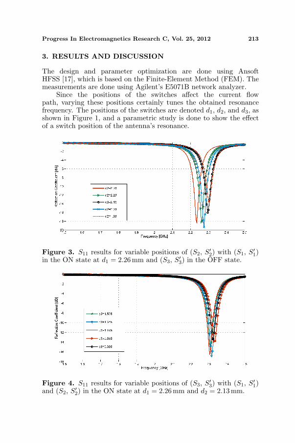
Simulated S11 plots in Figure 6 show frequency reconfigurabilityat 2.075 GHz, 2.145GHz, 2.295GHz, and 2.325 GHz for the differentswitching cases. A prototype of the antenna is fabricated. A photo ofthe prototype is shown in Figure 7.
The measured S11 plots are shown in Figure 8. They are in verygood agreement with the simulated ones.
In the results of Figures 6 and 8, switches in their ON statewere replaced by 1.2mm × 0.8mm copper strips. In the OFFstate, the copper strips were removed. The technique of replacingelectronic switches by copper strips in simulations is reported as
Figure 8. Measured S11 for switching Cases 0, 1, 2 and 3.
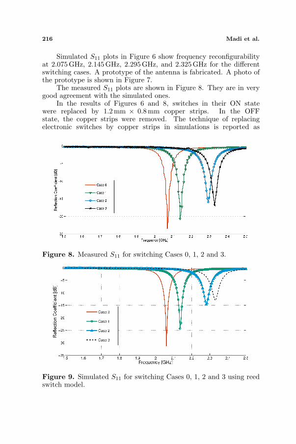
Figure 9. Simulated S11 for switching Cases 0, 1, 2 and 3 using reedswitch model.

Progress In Electromagnetics Research C, Vol. 25, 2012 217
valid in [14, 18, 19]. Using real switches, such as p-i-n diodes orRF MEMS, requires the design of their biasing networks. Thesebiasing networks will leave their effect on the antenna’s characteristics,especially the radiation patterns. However, some other types ofswitches do not need such biasing lines. They are actuated from belowthe ground plane, without affecting the radiation patterns. Theseinclude photoconductive switches [8], and reed switches [20, 21].
Figure 10. Design with more trims that widens the frequencyreconfigurability band.
Figure 11. Simulated S11 of the new antenna design shown inFigure 10 for two switching cases (all switches OFF and all switchesON) in comparison with the initial design.
218 Madi et al.
In [20], a Reed switch was modeled as a 0.2-Ω resistance when inthe ON state, and as a 0.1 pF capacitance in the OFF state. Usingthis model in the simulations, the S11 plots in Figure 9 are obtained.These results are almost identical to the ones in Figure 6, hence thevalidity of using the copper strip model.
The number of trims in the patch and their depth directly affectthe difference in the electrical length between Case 0 and Case 3,and hence the frequency reconfigurability range. A wider frequencyreconfigurability range is obtained by increasing the number of trimsand/or making them deeper. An example modified design is shown
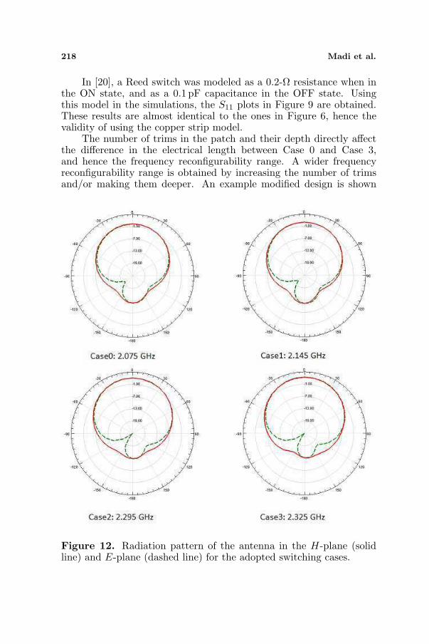
Figure 12. Radiation pattern of the antenna in the H-plane (solidline) and E-plane (dashed line) for the adopted switching cases.
Progress In Electromagnetics Research C, Vol. 25, 2012 219
in Figure 10. A comparison of the reflection coefficient plots forCases 0 and 3 of the original design and the modified design aregiven in Figure 11. It is shown that a 92% increase in the frequencyreconfigurability range is achieved. More deeper trims will furtherincrease this range.
For the design in Figure 1, the computed gain patterns in the E-and H-planes, for each of the switching cases, are shown in Figure 12.The four switching cases result in broadside patterns that remainconsistent over the four obtained operation bands. The obtained peakgain values are given in Table 1.
4. CONCLUSION
A cedar-shaped fractal antenna with frequency reconfiguration abilitywas presented. The space-filling property of the antenna served tolower its resonant frequency, and its self-similarity property to keepconsistent some of its characteristics. Frequency reconfigurabilitywas obtained by mounting and activating switches between thedifferent branches of the cedar. The switches allow modifying thecurrent path, and as a result the obtained resonance frequency. Thefrequency reconfigurability range for the fabricated prototype is 2–2.4GHz but can be adjusted by modifying the number and depthof the incorporated trims. Simulated and measured results were inagreement.
REFERENCES
1. Yang, S., Z. Chunna, P. Helen, A. Fathy, and V. Nair, “Frequency-reconfigurable antennas for multiradio wireless platforms,” IEEEMicrowave Magazine, Vol. 10, No. 1, 66–83, Feb. 2009.
2. Yu, Y. H. and C. P. Ji, “Research of fractal technology inthe design of multi-frequency antenna,” Microwave ConferenceProceedings (CJMW), 1–4, Apr. 2011.
3. Ramadan, A., M. Al-Husseini, K. Y. Kabalan, and A. El-Hajj,“Fractal-shaped reconfigurable antennas,” Microstrip Antennas,N. Nasimuddin (ed.), ISBN 978-953-307-247-0, InTech, Apr. 2011.
4. Balanis, C. A., Antenna Theory, Analysis and Design, John Wileyand Sons, 2005.
5. Rao, P. N. and N. V. S. N. Sarma, “A single feed circularlypolarized fractal shaped microstrip antenna with fractal slot,”PIERS Proceedings, 195–197, Hangzhou, China, Mar. 24–28, 2008.

220 Madi et al.
6. Ramadan, A., M. Al-Husseini, K. Y. Kabalan, A. El-Hajj, andJ. Costantine, “A compact Sierpinski-carpet-based patch antennafor UWB applications,” Proceedings of IEEE Antennas andPropagation Society International Symposium (APS-URSI 2009),1–4, Jun. 2009.
7. Al-Husseini, M., A. Ramadan, M. E. Zamudio,C. G. Christodoulou, A. El-Hajj, and K. Y. Kabalan, “AUWB antenna combined with a reconfigurable bandpass filter forcognitive radio applications,” The 2011 International Conferenceon Electromagnetics in Advanced Applications (ICEAA2011),Torino, Italy, Sep. 12–16, 2011.
8. Tawk, Y., M. Al-Husseini, S. Hemmady, A. R. Albrecht,G. Balakrishnan, and C. G. Christodoulou, “Implementation of acognitive radio front-end using optically reconfigurable antennas,”The 2010 International Conference on Electromagnetics inAdvanced Applications (ICEAA2010), Sydney, Australia, Sep. 20–24, 2010.
9. Cai, X., A. Wang, and W. Chen, “A circular disc-shaped antennawith frequency and pattern reconfigurable characteristics,” 2011China-Japan Joint Microwave Conference Proceedings (CJMW),1–4, Apr. 2011.
10. De Luis, J. R. and F. de Flaviis, “A reconfigurable dual frequencyswitched beam antenna array and phase shifter using PINdiodes,” IEEE Antennas and Propagation Society InternationalSymposium, 2009, APSURSI’09, 1–4, Jun. 2009.
11. Hamid, M. R., P. S. Hall, P. Gardner, and F. Ghanem, “Frequencyreconfigurable Vivaldi antenna,” 2010 Proceedings of the FourthEuropean Conference on Antennas and Propagation (EuCAP), 1–4, Apr. 2010.
12. Sondas, A., M. H. B. Ucar, and Y. E. Erdemli, “Tunable loop-loaded printed dipole antenna design,” Antennas and PropagationSociety International Symposium (APSURSI), 1–4, Jul. 2010.
13. Al-Husseini, M., J. Costantine, C. G. Christodoulou, S. E. Barbin,A. El-Hajj, and K. Y. Kabalan, “A reconfigurable frequency-notched UWB antenna with split-ring resonators,” MicrowaveConference Proceedings (APMC), 618–621, Dec. 2010.
14. Ramadan, A., K. Y. Kabalan, A. El-Hajj, S. Khoury, andM. Al-Husseini, “A reconfigurable U-Koch microstrip antennafor wireless applications,” Progress In Electromagnetics Research,Vol. 93, 355–367, 2009.
15. Anagnostou, D. E., G. Zheng, M. T. Chryssomallis, J. C. Lyke,G. E. Ponchak, J. Papapolymerou, and C. G. Christodoulou,
Progress In Electromagnetics Research C, Vol. 25, 2012 221
“Design, fabrication, and measurements of an RF-MEMS-based self-similar reconfigurable antenna,” IEEE Transactions onAntennas and Propagation, Vol. 54, No. 2, 422–432, Feb. 2006.
16. Guney, K., “Resonant frequency of a triangular microstripantenna,” Microwave and Optical Technology Letters, Vol. 6,No. 9, Jul. 1993.
17. Ansoft HFSS, Pittsburg, PA 15219, USA.18. Costantine, J., C. G. Christodoulou, and S. E. Barbin, “A new
reconfigurable multi band patch antenna,” SBMO/IEEE MTT-S International Microwave and Optoelectronics Conference, 2007,IMOC 2007, 75–78, Oct. 2007.
19. Zammit, J. A. and A. Muscat, “Tunable microstrip antenna usingswitchable patches,” Antennas and Propagation Conference, 2008,LAPC 2008, 233–236, Loughborough, Mar. 2008.
20. Wu, C., T. Wang, A. Ren, and D. G. Michelson, “Implementationof reconfigurable patch antennas using reed switches,” IEEEAntennas and Wireless Propagation Letters, Vol. 10, 2011.
21. http://www.meder.com.