DESIGN AND ANALYSIS OF C TYPE HYDRAULIC PRESS STRUCTURE AND CYLINDER
10
INTERNATIONAL JOURNAL OF RESEARCH IN AERONAUTICAL AND MECHANICAL ENGINEERING Vol.2 Issue.3, March 2014. Pgs: 47-56 B.PARTHIBAN , P.EAZHUMALI , S.KARTHI , P.KALIMUTHU 47 ISSN (ONLINE): 2321-3051 INTERNATIONAL JOURNAL OF RESEARCH IN AERONAUTICAL AND MECHANICAL ENGINEERING DESIGN AND ANALYSIS OF C TYPE HYDRAULIC PRESS STRUCTURE AND CYLINDER B.PARTHIBAN 1 , P.EAZHUMALI 2 , S.KARTHI 2 , P.KALIMUTHU 2 1 Asst Prof., Department of Mechanical Engineering, Jay ShriRam Group of Institutions, Tirupur. 2 Final Year Student, Department of Mechanical Engineering, Jay ShriRam Group of Institutions, Tirupur. Abstract A hydraulic press is a machine using a hydraulic cylinder to generate a compressive force. Frame and cylinder are the main components of the hydraulic press. In this project press frame and cylinder are designed by the design procedure. Press frame and cylinder are analysed to improve its performance and quality for press working operation. Structural analysis has become an integral part of the product design. The frame and cylinder are modeled by using modeling software CATIA. Structural analysis has been applied on C frame hydraulic press structure and cylinder by using analysing software ANSYS. An integrated approach has been developed to verify the structural performance and stress strain distributions are plotted by using ANSYS software. According to the structural values the dimensions of the frame and cylinder are modified to perform the functions satisfactory. Keywords: HYDRAULIC; CYLINDER; Betz Law; Rotor; Brakes. I. INTRODUCTION HYDRAULIC PRESS In hydraulic press, the force generation, transmission and amplification are achieved using fluid under pressure. The liquid system exhibits the characteristics of a solid and provides a very positive and rigid medium of power transmission and amplification. In a simple application, a smaller piston transfers fluid under high pressure to a cylinder having a larger piston area, thus amplifying the force. There is easy transmissibility of large amount of energy with practically unlimited force amplification. It has also a very low inertia effect.
-
Upload
independent -
Category
Documents
-
view
6 -
download
0
Transcript of DESIGN AND ANALYSIS OF C TYPE HYDRAULIC PRESS STRUCTURE AND CYLINDER
INTERNATIONAL JOURNAL OF RESEARCH IN AERONAUTICAL AND MECHANICAL ENGINEERING
Vol.2 Issue.3,
March 2014.
Pgs: 47-56
B.PARTHIBAN , P.EAZHUMALI , S.KARTHI , P.KALIMUTHU 47
ISSN (ONLINE): 2321-3051
INTERNATIONAL JOURNAL OF RESEARCH IN AERONAUTICAL AND MECHANICAL ENGINEERING
DESIGN AND ANALYSIS OF C TYPE HYDRAULIC PRESS STRUCTURE AND CYLINDER
B.PARTHIBAN 1 , P.EAZHUMALI 2 , S.KARTHI 2 , P.KALIMUTHU 2
1 Asst Prof., Department of Mechanical Engineering, Jay ShriRam Group of Institutions, Tirupur. 2Final Year Student, Department of Mechanical Engineering, Jay ShriRam Group of Institutions, Tirupur.
Abstract
A hydraulic press is a machine using a hydraulic cylinder to generate a
compressive force. Frame and cylinder are the main components of the hydraulic press. In this project press frame and cylinder are designed by the design procedure. Press frame and cylinder are analysed to improve its performance and quality for press working operation. Structural analysis has become an integral part of the product design. The frame and cylinder are modeled by using modeling software CATIA. Structural analysis has been applied on C frame hydraulic press structure and cylinder by using analysing software ANSYS. An integrated approach has been developed to verify the structural performance and stress strain distributions are plotted by using ANSYS software. According to the structural values the dimensions of the frame and cylinder are modified to perform the functions satisfactory.
Keywords: HYDRAULIC; CYLINDER; Betz Law; Rotor; Brakes.
I. INTRODUCTION
HYDRAULIC PRESS
In hydraulic press, the force generation, transmission and amplification are achieved using fluid under pressure. The liquid system exhibits the characteristics of a solid and provides a very positive and rigid medium of power transmission and amplification. In a simple application, a smaller piston transfers fluid under high pressure to a cylinder having a larger piston area, thus amplifying the force. There is easy transmissibility of large amount of energy with practically unlimited force amplification. It has also a very low inertia effect.
INTERNATIONAL JOURNAL OF RESEARCH IN AERONAUTICAL AND MECHANICAL ENGINEERING
Vol.2 Issue.3,
March 2014.
Pgs: 47-56
B.PARTHIBAN , P.EAZHUMALI , S.KARTHI , P.KALIMUTHU 48
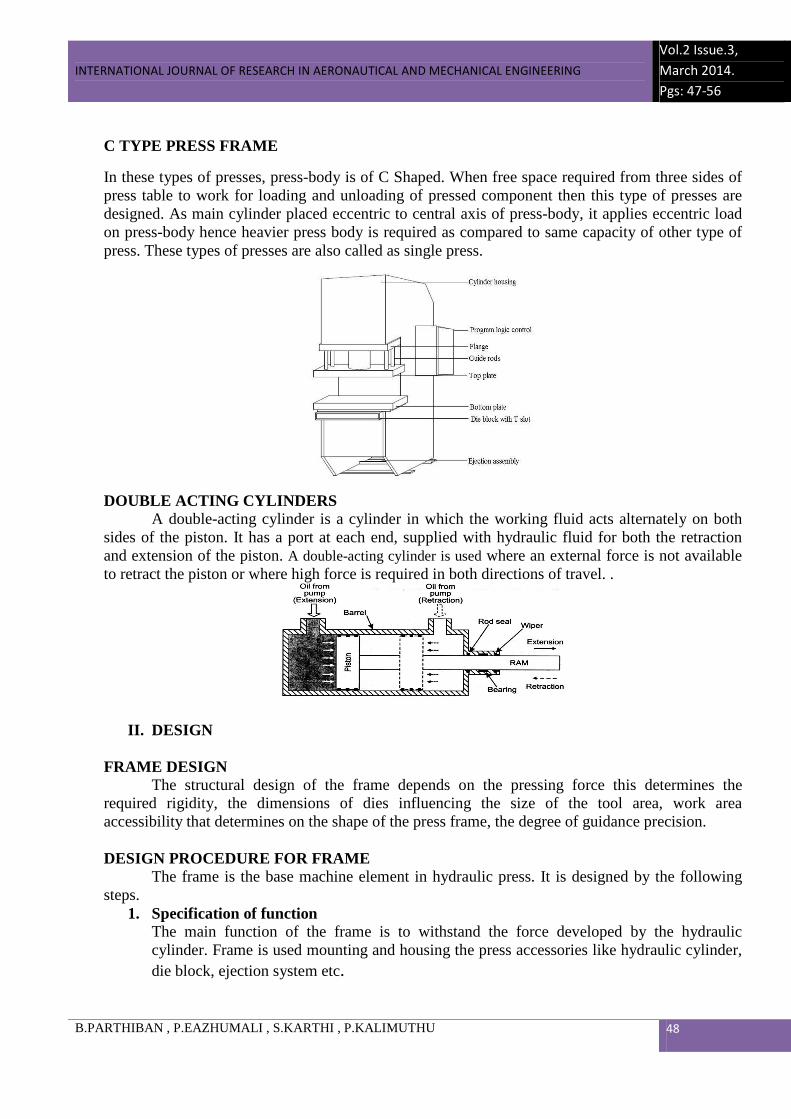
C TYPE PRESS FRAME
In these types of presses, press-body is of C Shaped. When free space required from three sides of press table to work for loading and unloading of pressed component then this type of presses are designed. As main cylinder placed eccentric to central axis of press-body, it applies eccentric load on press-body hence heavier press body is required as compared to same capacity of other type of press. These types of presses are also called as single press.
DOUBLE ACTING CYLINDERS
A double-acting cylinder is a cylinder in which the working fluid acts alternately on both sides of the piston. It has a port at each end, supplied with hydraulic fluid for both the retraction and extension of the piston. A double-acting cylinder is used where an external force is not available to retract the piston or where high force is required in both directions of travel. .
II. DESIGN
FRAME DESIGN The structural design of the frame depends on the pressing force this determines the
required rigidity, the dimensions of dies influencing the size of the tool area, work area accessibility that determines on the shape of the press frame, the degree of guidance precision.
DESIGN PROCEDURE FOR FRAME
The frame is the base machine element in hydraulic press. It is designed by the following steps.
1. Specification of function The main function of the frame is to withstand the force developed by the hydraulic cylinder. Frame is used mounting and housing the press accessories like hydraulic cylinder, die block, ejection system etc.
INTERNATIONAL JOURNAL OF RESEARCH IN AERONAUTICAL AND MECHANICAL ENGINEERING
Vol.2 Issue.3,
March 2014.
Pgs: 47-56
B.PARTHIBAN , P.EAZHUMALI , S.KARTHI , P.KALIMUTHU 49
2. Determination of forces The weight of the cylinder and the cylinder load is the major forces acting on the frame
structure. Press capacity P = 588600 N 3. Selection of materials
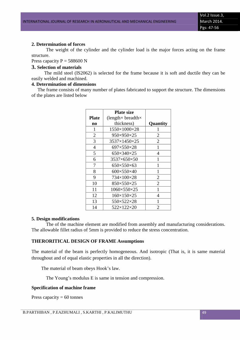
The mild steel (IS2062) is selected for the frame because it is soft and ductile they can be easily welded and machined. 4. Determination of dimensions The frame consists of many number of plates fabricated to support the structure. The dimensions of the plates are listed below
Plate no
Plate size (length× breadth×
thickness) Quantity 1 1550×1000×28 1 2 950×950×25 2 3 3537×1450×25 2 4 697×550×28 1 5 650×340×25 4 6 3537×650×50 1 7 650×550×63 1 8 600×550×40 1 9 734×100×28 2 10 850×550×25 2 11 1060×550×25 1 12 160×150×25 4 13 550×522×28 1 14 522×122×20 2
5. Design modifications
The of the machine element are modified from assembly and manufacturing considerations. The allowable fillet radius of 5mm is provided to reduce the stress concentration.
THERORITICAL DESIGN OF FRAME Assumptions
The material of the beam is perfectly homogeneous. And isotropic (That is, it is same material throughout and of equal elastic properties in all the direction).
The material of beam obeys Hook’s law.
The Young’s modulus E is same in tension and compression.
Specification of machine frame
Press capacity = 60 tonnes

INTERNATIONAL JOURNAL OF RESEARCH IN AERONAUTICAL AND MECHANICAL ENGINEERING
Vol.2 Issue.3,
March 2014.
Pgs: 47-56
B.PARTHIBAN , P.EAZHUMALI , S.KARTHI , P.KALIMUTHU 50
Tensile strength= 410 26 /10 mmN×
Density= 7850 kg/ 3m
Young’s Modulus= 2.1 25 /10 mmN× .
Poisons Ratio= 0.3.
Factor of Safety= 4.0
Max Allowable Stress σ =410/4
σ = 102 N/ 2mm
Formulas and calculations
The frame subjected to direct tensile stress and bending stresses
bendingtensiletotal σσσ += N/ 2mm
I
YM
A
P b+=σ N/ 2mm
Where
σ = Permissible stress in N/ 2mm
P = Applied load/ Force in N
A= Area of the plate section in 2mm
bM = Bending moment in N. mm
x= Perpendicular Distance in mm
y = Distance from the neutral surface to
the extreme fiber in mm
I = Moment of inertia in 4mm
P =60 tonnes
Applied load P= 60000 81.9× N
P = 588600 N
Breadth b = 900 mm
Thickness d= 25mm
INTERNATIONAL JOURNAL OF RESEARCH IN AERONAUTICAL AND MECHANICAL ENGINEERING
Vol.2 Issue.3,
March 2014.
Pgs: 47-56
B.PARTHIBAN , P.EAZHUMALI , S.KARTHI , P.KALIMUTHU 51
Area = b d× = 22500 2mm
tensileσ = 588600/22500 = 26.16 N/ 2mm
bendingσ = I
yM b × N/ 2mm
Bending moment bM = xP ×)2/(
Perpendicular Distance x= 11850 in mm
bM = 294300×11850
bM = 3487455000 N.mm
Y= 25 mm Moment
of inertia for rectangular plate sections I = 12
3db 4mm I = 1518750000
4mm
bendingσ = (3487455000 ×25) / (1518750000)
bendingσ = 57. 41 N/ 2mm
totalσ = (26.16 + 57.41) N/ 2mm
totalσ = 83.57 N/ 2mm
Max Allowable Stress σ =410/4 = 102 N/ 2mm
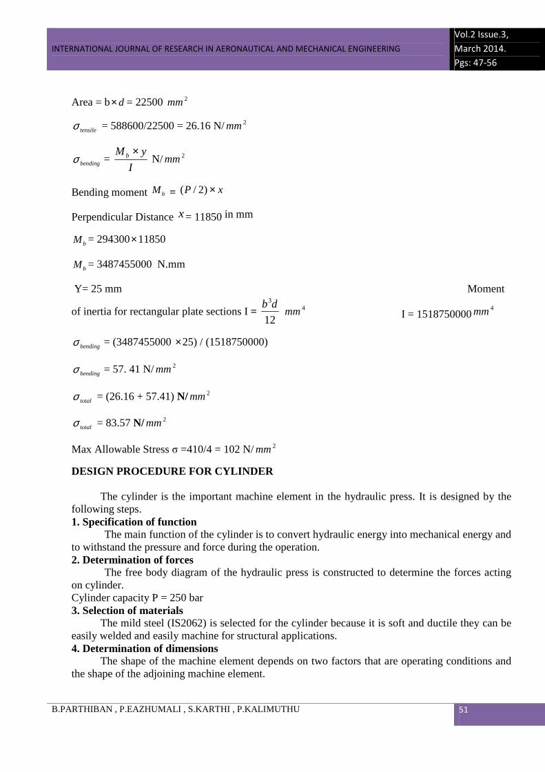
DESIGN PROCEDURE FOR CYLINDER
The cylinder is the important machine element in the hydraulic press. It is designed by the following steps. 1. Specification of function
The main function of the cylinder is to convert hydraulic energy into mechanical energy and to withstand the pressure and force during the operation. 2. Determination of forces
The free body diagram of the hydraulic press is constructed to determine the forces acting on cylinder. Cylinder capacity P = 250 bar 3. Selection of materials
The mild steel (IS2062) is selected for the cylinder because it is soft and ductile they can be easily welded and easily machine for structural applications. 4. Determination of dimensions
The shape of the machine element depends on two factors that are operating conditions and the shape of the adjoining machine element.
INTERNATIONAL JOURNAL OF RESEARCH IN AERONAUTICAL AND MECHANICAL ENGINEERING
Vol.2 Issue.3,
March 2014.
Pgs: 47-56
B.PARTHIBAN , P.EAZHUMALI , S.KARTHI , P.KALIMUTHU 52
Length : 1112 mm Inner diameter : 200 mm Outer diameter : 288 mm
5. Design modifications The of the machine element are modified from assembly and manufacturing considerations.
The allowable fillet radius of 5mm is provided to reduce the stress concentration.
III. ANALYSIS
STRUCTURAL ANALYSIS OF FRAME AND CYLINDER The performance of a hydraulic press depends, largely, upon the behavior of its structure
during operation. The analysis of hydraulic press structure is needed to increased their performance and productivity. The deformation of press structure during the loading condition is analysed to change the dimensions of plates.
For the hydraulic cylinder, the loading condition is defined with applying the pressure to the inner surface of the cylinder. The amount of pressure developed inside the cylinder during the loading condition is analysed and the wall thickness, flange thickness and number and size of bolts are changed.
ANALYSIS PROCEDURE
STEP 1
The C type hydraulic press frame and double acting cylinder are created from the modeling software CATIA.
STEP 2
Now, the model is opened in simulation software ANSYS for analyzing stress strain distribution.
STEP 3
Open the model in Simulation, establish units, and set up a structural analysis.
STEP 4
Apply fixed support by selecting the face shown and choosing Supports Fixed Support and also Load from the toolbar.
STEP 5
Solve the analysis. Choose Solve from the toolbar.
STEP 6
Review the results of the structural analysis. Highlight the Shape Finder object. The results show suggested areas of material removal.
INTERNATIONAL JOURNAL OF RESEARCH IN AERONAUTICAL AND MECHANICAL ENGINEERING
Vol.2 Issue.3,
March 2014.
Pgs: 47-56
B.PARTHIBAN , P.EAZHUMALI , S.KARTHI , P.KALIMUTHU 53
STEP 7
Simulation of press structure is done in ANSYS software.
STEP 8
From the above results, the metal removal areas in the frame can be determined and removed to reduce the weight and cost.
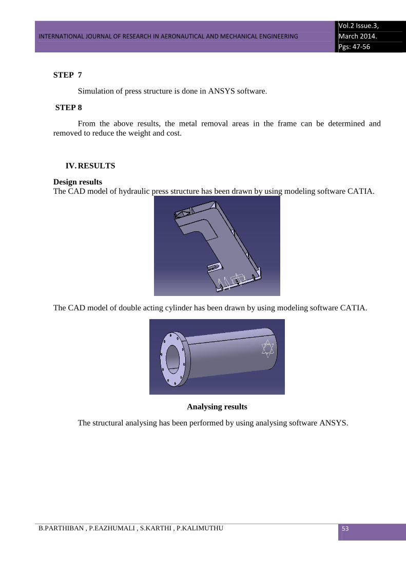
IV. RESULTS
Design results The CAD model of hydraulic press structure has been drawn by using modeling software CATIA.
The CAD model of double acting cylinder has been drawn by using modeling software CATIA.
Analysing results
The structural analysing has been performed by using analysing software ANSYS.
INTERNATIONAL JOURNAL OF RESEARCH IN AERONAUTICAL AND MECHANICAL ENGINEERING
Vol.2 Issue.3,
March 2014.
Pgs: 47-56
B.PARTHIBAN , P.EAZHUMALI , S.KARTHI , P.KALIMUTHU 54
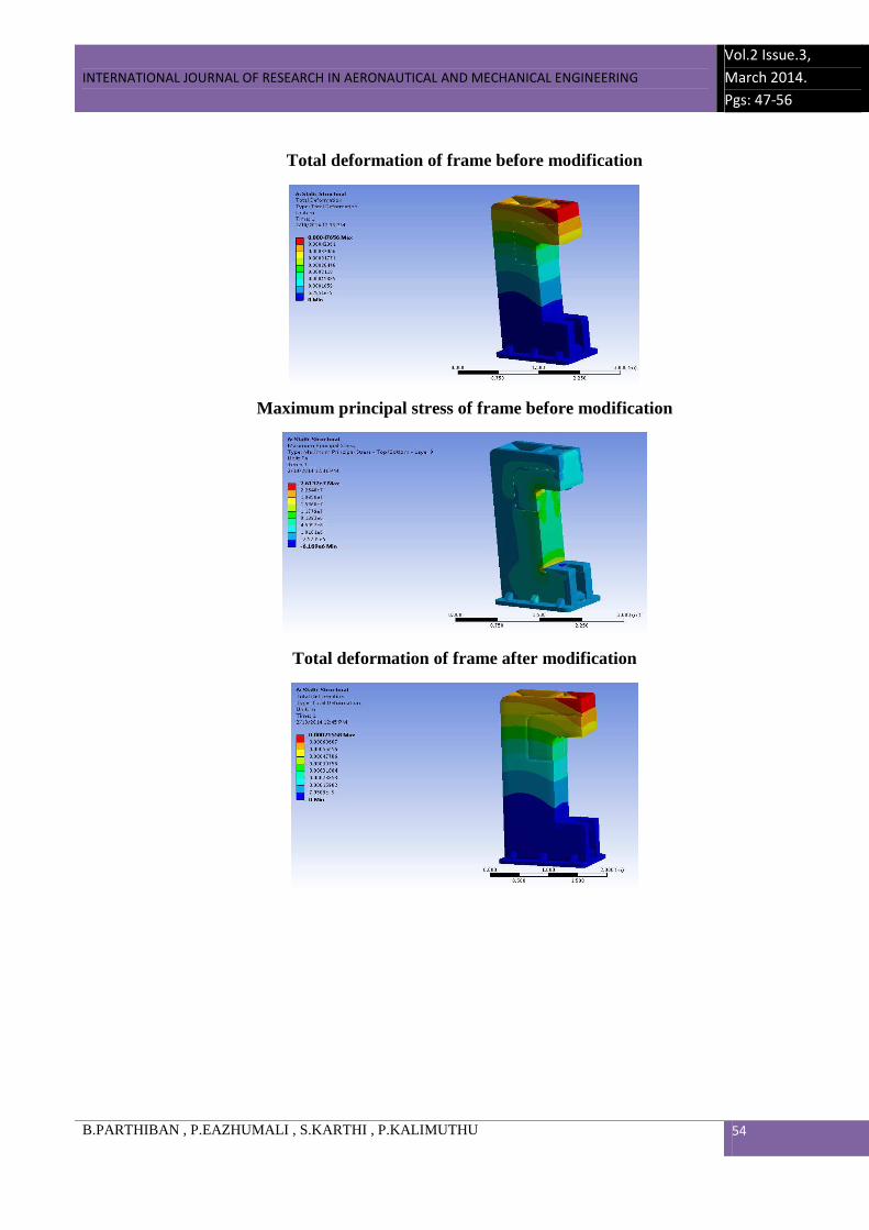
Total deformation of frame before modification
Maximum principal stress of frame before modification
Total deformation of frame after modification
INTERNATIONAL JOURNAL OF RESEARCH IN AERONAUTICAL AND MECHANICAL ENGINEERING
Vol.2 Issue.3,
March 2014.
Pgs: 47-56
B.PARTHIBAN , P.EAZHUMALI , S.KARTHI , P.KALIMUTHU 55
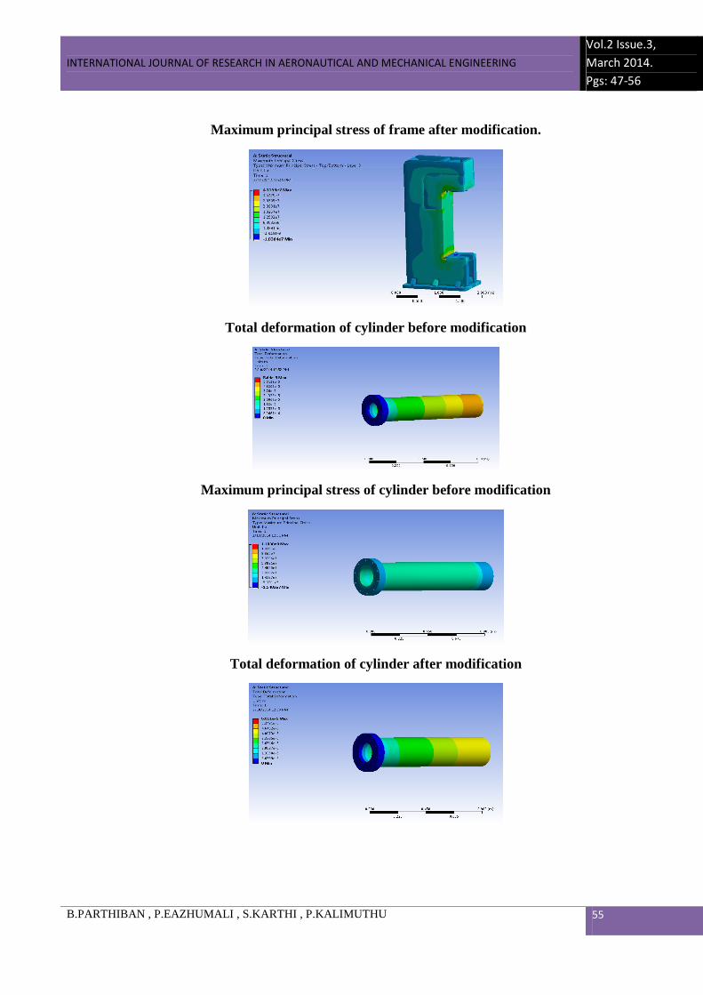
Maximum principal stress of frame after modification.
Total deformation of cylinder before modification
Maximum principal stress of cylinder before modification
Total deformation of cylinder after modification
INTERNATIONAL JOURNAL OF RESEARCH IN AERONAUTICAL AND MECHANICAL ENGINEERING
Vol.2 Issue.3,
March 2014.
Pgs: 47-56
B.PARTHIBAN , P.EAZHUMALI , S.KARTHI , P.KALIMUTHU 56
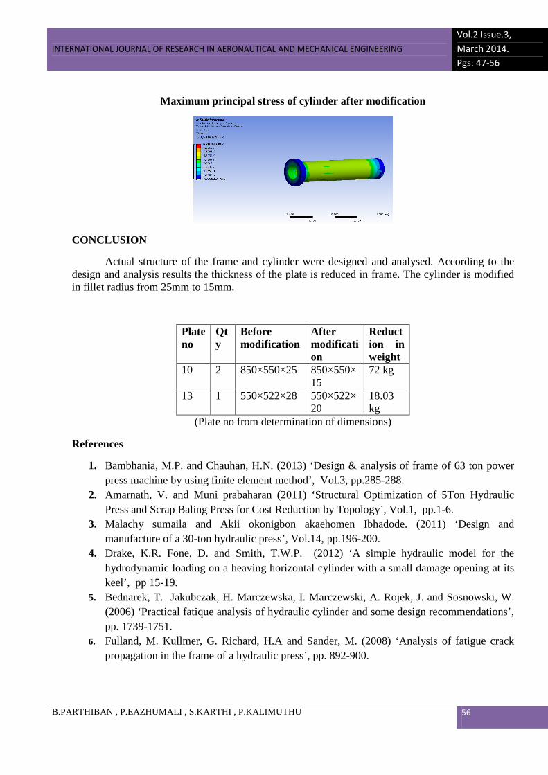
Maximum principal stress of cylinder after modification
CONCLUSION
Actual structure of the frame and cylinder were designed and analysed. According to the design and analysis results the thickness of the plate is reduced in frame. The cylinder is modified in fillet radius from 25mm to 15mm.
Plate no
Qty
Before modification
After modification
Reduction in weight
10 2 850×550×25 850×550×15
72 kg
13 1 550×522×28 550×522×20
18.03 kg
(Plate no from determination of dimensions)
References
1. Bambhania, M.P. and Chauhan, H.N. (2013) ‘Design & analysis of frame of 63 ton power press machine by using finite element method’, Vol.3, pp.285-288.
2. Amarnath, V. and Muni prabaharan (2011) ‘Structural Optimization of 5Ton Hydraulic Press and Scrap Baling Press for Cost Reduction by Topology’, Vol.1, pp.1-6.
3. Malachy sumaila and Akii okonigbon akaehomen Ibhadode. (2011) ‘Design and manufacture of a 30-ton hydraulic press’, Vol.14, pp.196-200.
4. Drake, K.R. Fone, D. and Smith, T.W.P. (2012) ‘A simple hydraulic model for the hydrodynamic loading on a heaving horizontal cylinder with a small damage opening at its keel’, pp 15-19.
5. Bednarek, T. Jakubczak, H. Marczewska, I. Marczewski, A. Rojek, J. and Sosnowski, W. (2006) ‘Practical fatique analysis of hydraulic cylinder and some design recommendations’, pp. 1739-1751.
6. Fulland, M. Kullmer, G. Richard, H.A and Sander, M. (2008) ‘Analysis of fatigue crack propagation in the frame of a hydraulic press’, pp. 892-900.