DESCRIPTION OF THE PROPOSED DEVELOPMENT
83
Proposed Croagh Wind Farm Development Environmental Impact Assessment Report EIAR – 2020.07.06 – 180511 – F 4-1 4. DESCRIPTION OF THE PROPOSED DEVELOPMENT 4.1 Introduction This section of the Environmental Impact Assessment Report (EIAR) describes the development and its component parts which is the subject of a proposed application for planning permission to Leitrim County Council and Sligo County Council, (‘the Proposed Development’). The Proposed Development comprises: i. Construction of 10 No. wind turbines with a maximum overall blade tip height of up to 170 metres, and associated hardstand areas; ii. 1 no. 38kV permanent electrical substation including a control building with welfare facilities, all associated electrical plant and equipment, security fencing, all associated underground cabling, waste water holding tank and all ancillary works; iii. 1 no. permanent Meteorological Mast with a maximum height of up to 100 metres; iv. All associated underground electrical and communications cabling connecting the turbines to the proposed wind farm substation; v. All works associated with the connection of the proposed wind farm to the national electricity grid, via underground cabling to the existing Garvagh substation; vi. Upgrade of existing tracks and roads, provision of new site access roads and hardstand areas; vii. The partial demolition and alteration of two agricultural buildings in the townlands of Sheena and associated junction access and road works to the existing yard, agricultural buildings and agricultural lands in the townlands of Sheena and Derrybofin to provide a link road primarily for construction traffic off the R280. This link road will be used for the delivery of abnormal loads to the site during the construction period and may be used during the operational period if necessary or to facilitate the decommissioning of the wind farm. Following construction, access to the link road will be closed off and the yard/agricultural building will revert to its use for agricultural purposes except if and when required for delivery of abnormal loads during the operational period of the windfarm or to facilitate the decommissioning of the wind farm; viii. 1 no. borrow pit; ix. 2 no. peat and spoil repository areas x. 2 no. temporary construction compounds; xi. Recreation and amenity works, including marked trails, boardwalk and viewing area provision of a permanent amenity car park, and associated recreation and amenity signage xii. Site Drainage; xiii. Permanent Signage; xiv. Ancillary Forestry Felling to facilitate construction and operation of the proposed development; and xv. All associated site development works This application seeks a ten-year planning permission and 30-year operational life from the date of commissioning of the entire wind farm. The development of the proposed wind farm development will require the felling of approximately 55.1 hectares of commercial forestry which will require replanting elsewhere in the state. Details regarding the area to be felled are outlined in Section 4.3.10 below. The Forest Service policy on the granting of felling licences requires replanting of forestry on a hectare by hectare basis. Three potential forestry replacement lands have been identified for assessment purposes. These lands, located in Counties Cavan, Roscommon and Wicklow, have all been granted Forest Service Technical Approval for afforestation and these or similarly approved lands will be used for replanting should the Proposed Development receive planning permission. All elements of the Proposed Development described in the list above and the forestry replacement lands have been assessed as part of this EIAR.
-
Upload
khangminh22 -
Category
Documents
-
view
0 -
download
0
Transcript of DESCRIPTION OF THE PROPOSED DEVELOPMENT

Proposed Croagh Wind Farm Development
Environmental Impact Assessment Report
EIAR – 2020.07.06 – 180511 – F
4-1
4. DESCRIPTION OF THE PROPOSED DEVELOPMENT
4.1 Introduction This section of the Environmental Impact Assessment Report (EIAR) describes the development and its component parts which is the subject of a proposed application for planning permission to Leitrim County Council and Sligo County Council, (‘the Proposed Development’). The Proposed Development comprises:
i. Construction of 10 No. wind turbines with a maximum overall blade tip height of up to 170 metres, and associated hardstand areas;
ii. 1 no. 38kV permanent electrical substation including a control building with welfare facilities, all associated electrical plant and equipment, security fencing, all associated underground cabling, waste water holding tank and all ancillary works;
iii. 1 no. permanent Meteorological Mast with a maximum height of up to 100 metres; iv. All associated underground electrical and communications cabling connecting the turbines to the
proposed wind farm substation; v. All works associated with the connection of the proposed wind farm to the national electricity
grid, via underground cabling to the existing Garvagh substation; vi. Upgrade of existing tracks and roads, provision of new site access roads and hardstand areas; vii. The partial demolition and alteration of two agricultural buildings in the townlands of Sheena
and associated junction access and road works to the existing yard, agricultural buildings and agricultural lands in the townlands of Sheena and Derrybofin to provide a link road primarily for construction traffic off the R280. This link road will be used for the delivery of abnormal loads to the site during the construction period and may be used during the operational period if necessary or to facilitate the decommissioning of the wind farm. Following construction, access to the link road will be closed off and the yard/agricultural building will revert to its use for agricultural purposes except if and when required for delivery of abnormal loads during the operational period of the windfarm or to facilitate the decommissioning of the wind farm;
viii. 1 no. borrow pit; ix. 2 no. peat and spoil repository areas x. 2 no. temporary construction compounds; xi. Recreation and amenity works, including marked trails, boardwalk and viewing area provision of
a permanent amenity car park, and associated recreation and amenity signage xii. Site Drainage; xiii. Permanent Signage; xiv. Ancillary Forestry Felling to facilitate construction and operation of the proposed development;
and xv. All associated site development works
This application seeks a ten-year planning permission and 30-year operational life from the date of commissioning of the entire wind farm.
The development of the proposed wind farm development will require the felling of approximately 55.1 hectares of commercial forestry which will require replanting elsewhere in the state. Details regarding the area to be felled are outlined in Section 4.3.10 below. The Forest Service policy on the granting of felling licences requires replanting of forestry on a hectare by hectare basis. Three potential forestry replacement lands have been identified for assessment purposes. These lands, located in Counties Cavan, Roscommon and Wicklow, have all been granted Forest Service Technical Approval for afforestation and these or similarly approved lands will be used for replanting should the Proposed Development receive planning permission.
All elements of the Proposed Development described in the list above and the forestry replacement lands have been assessed as part of this EIAR.

Proposed Croagh Wind Farm Development
Environmental Impact Assessment Report
EIAR – 2020.07.06 – 180511 – F
4-2
4.2 Development Layout The layout of the Proposed Development has been designed to minimise the potential environmental effects of the wind farm, while at the same time maximising the energy yield of the wind resource passing over the site. A constraints study, as described in Section 3.6.1 of this EIAR, has been carried out to ensure that turbines and ancillary infrastructure are located in the most appropriate areas of the site. The Proposed Development layout makes maximum use of the existing access roads and tracks within the site.
The overall layout of the Proposed Development is shown on Figure 4-1. This drawing shows the proposed locations of the wind turbines, electricity substation, grid connection route, borrow pit, peat and spoil repositories, construction compounds, internal roads layout, the construction access road and the main site entrance. Detailed site layout drawings of the Proposed Development are included in Appendix 4-1 to this EIAR.
4.3 Development Components
4.3.1 Wind Turbines
4.3.1.1 Turbine Locations
The proposed wind turbine layout has been optimised using industry standard wind farm design software to maximise the energy yield from the site, while maintaining sufficient distances between the proposed turbines to ensure turbulence and wake effects do not compromise turbine performance. The Grid Reference coordinates of the proposed turbine locations are listed in Table 4-1 below.
Table 4-1 Propose Wind Turbine Locations and Elevations
Turbine No. Irish Transverse Mercator Co-ordinates Elevation (m OD)
Easting (m) Northing (m)
1 583322 823639 271
2 583831 824112 241
3 583648 823314 287
4 584,223 823,820 277
5 584259 823347 294
6 584841 823616 294
7 584968 823032 291
8 585523 822935 300
9 586144 822595 323
10 584676 822493 298

MKO Ltd., Tuam Road, Galway, Ireland, H91 VW84. Email: [email protected] Tel: +353 (0)91 735611
MAP TITLE:
PROJECT TITLE:
DRAWING BY: CHECKED BY:
MAP NO.:
ISSUE NO.:
SCALE:
DATE:
Ordnance Survey Ireland Licence No. AR 0021820© Ordnance Survey Ireland/Government of Ireland
Eoin McCarthy Michael Watson04-06-2020
1:22,500
180511-2020.06.04-F
Figure 4.1Proposed Development Layout180511 - Croagh Wind Farm
Map Legend
Co. Letrim/ Co. Sligo County Boundary
Regional Road
Local Roads
Existing Access Road/Track
Proposed Visitor Carpark Location(Operational Phase)
Proposed Viewing Platform
Proposed Boardwalk
Proposed Amenity Walkways
Proposed New Site Roads
Existing Roads - Upgrade Proposed
Existing 110kV Garvagh Substation Location
Proposed 38kV Underground GridConnection Cabling Route
Road Widening Works Area
Proposed Peat & Spoil Repository
Proposed Borrow Pit
Proposed Construction Compound
Proposed 38kV Substation Compound
Proposed Met Mast Location
Proposed Turbine Location
EIAR Site Boundary

Proposed Croagh Wind Farm Development
Environmental Impact Assessment Report
EIAR – 2020.07.06 – 180511 – F
4-3
4.3.1.2 Turbine Type
Wind turbines use the energy from the wind to generate electricity. A wind turbine, as shown in Plate 4-1 below, consists of four main components:
Foundation unit Tower Nacelle (turbine housing) Rotor
Plate 4-1 Wind turbine components
The proposed wind turbines will have a tip height of up to 170 metres. Within this size envelope, various configurations of hub height, rotor diameter and ground to blade tip height may be used. The exact make and model of the turbine will be dictated by a competitive tender process, but it will not exceed a tip height of up to 170 metres. Modern wind turbines from the main turbine manufacturers have evolved to share a common appearance and other major characteristics, with only minor cosmetic differences differentiating one from another. The wind turbines that will be installed on the site will be conventional three-blade turbines, that will be geared to ensure the rotors of all turbines rotate in the same direction at all times. The turbines will be grey matt in colour.
For the purposes of this EIAR, various types and sizes of wind turbines within the 170-metre tip height envelope have been selected and considered in the relevant sections of the EIAR to assess the worst-case scenario. Turbine design parameters have a bearing on the assessment of shadow flicker, noise, visual impact, traffic and transport and ecology (specifically birds), as addressed elsewhere in this EIAR. In each EIAR section that requires the consideration of turbine parameters as part of the impact assessment, the worst-case turbine design parameters that have been used in the impact assessment are specified.
A drawing of the proposed wind turbine is shown in Figure 4-2. The individual components of a typical geared wind turbine nacelle and hub are shown in Figure 4-3 below.

Plan
Fornt/Sectional Elevation Side/Section Elevation
Nacelle
Blade
Foundation
Access Stairway
Ground Level
Tower
Blade
Blade
Nacelle
Tower
Foundation
Access Stairway
Ground Level
Up
To 1
70 m
etre
s To
p of
Fou
ndat
ion
- Bla
de T
ip H
eigh
t
N
3000 40000
1200
0
1900
0
55000
3500
0
13000
3000
Secondary Hardstand
Secondary Hardstand
Main Hardstand
TurbineFoundation
Temporary Works Area Temporary Works Area
Roadway
Turbine Excavation Area
Positive drainagefrom turbine base
Outfalls to proposed drainageor new outfall to lower grounddepending on site topography
Treatment at outfall,if connection to proposedturbine drainage not possible
North point will vary depending on turbine location,please refer to individual layout maps.
natural slope oflocal topography
natural slope oflocal topography
Figure 4-2DRAWING TITLE:
Typical Wind TurbineHardstanding & Elevations
Drawing Notes1. Proposed wind turbines to have a maximum ground
to blade tip height of up to 170m.
2. Exact make and model of the turbine to be dictated bya competitive tender process.
3. Installed wind turbine not to exceed maximum sizeenvelope set out above in any blade length andhub-height configuration.
4. Turbine foundation diameter may vary.
5. Ground level represents the top of turbine foundation.
PROJECT TITLE:
1:500 @A1 03.07.2020180511
Joseph O Brien Eoin McCarthy
Croagh Wind Farm, Co. LeitrimDRAWING BY: CHECKED BY:
DRAWING No.:
SCALE: DATE:
PROJECT No.:180511 - 45
MKOTuam Road, Galway
Ireland, H91 VW84
+353 (0) 91 735611
email: [email protected]
Website: www.mkoireland.ie

Proposed Croagh Wind Farm Development
Environmental Impact Assessment Report
EIAR – 2020.07.06 – 180511 – F
4-4
Figure 4-3 Turbine nacelle and hub components
Figure 4-2 shows a typical turbine base layout, including turbine foundation, hard standing area, assembly area, access road and surrounding works area.
4.3.1.3 Turbine Foundations
Each wind turbine is secured to a reinforced concrete foundation that is installed below the finished ground level. The size of the foundation will be dictated by the turbine manufacturer, and the final turbine selection will be the subject of a competitive tender process. Different turbine manufacturers use different shaped turbine foundations, ranging from circular to hexagonal and square, depending on the requirements of the final turbine supplier and a foundation area large enough to accommodate modern turbine models has been assessed in this EIAR. The turbine foundation transmits any load on the wind turbine into the ground. The typical horizontal and vertical extent of a turbine’s foundation is shown in Figure 4-2.
After the foundation level of each turbine has been formed on competent strata or using piling methods, the bottom section of the turbine tower “Anchor Cage” is levelled and reinforcing steel is then built up around and through the anchor cage. The outside of the foundation is shuttered with demountable formwork to allow the pouring of concrete and is backfilled accordingly with appropriate granular fill to finished surface level (Plate 4-2 below).

Proposed Croagh Wind Farm Development
Environmental Impact Assessment Report
EIAR – 2020.07.06 – 180511 – F
4-5
Plate 4-2 Turbine 'Anchor Cage' and finished turbine base
4.3.1.4 Hard Standing Areas
Hard standing areas consisting of levelled and compacted hardcore are required around each turbine base to facilitate access, turbine assembly and turbine erection. The hard-standing areas are typically used to accommodate cranes used in the assembly and erection of the turbine, offloading and storage of turbine components, and generally provide a safe, level working area around each turbine position. The hard-standing areas are extended to cover the turbine foundations once the turbine foundation is in place. The sizes, arrangement and positioning of hard standing areas are dictated by turbine suppliers. The hard-standing area is intended to accommodate a crane during turbine assembly and erection. The proposed hard standing areas shown on the detailed layout drawings included in Appendix 4-1 to this report are indicative of the sizes required, but the extent of the required areas at each turbine location may be optimised on-site depending on topography, position of the site access road, the proposed turbine position and the turbine supplier’s exact requirements.
4.3.1.5 Assembly Area
Levelled assembly areas will be located on either side of the hard-standing area as shown on Figure 4-2. These assembly areas are required for offloading turbine blades, tower sections and hub from trucks until such time as they are ready to be lifted into position by cranes and to assist the main crane during turbine assembly. The exact location and number of assembly areas will be determined in consultation with the selected turbine manufacturer.
4.3.1.6 Power Output
It is anticipated the proposed wind turbines will have a rated electrical power output in the 3 to 5-megawatt (MW) range depending on further wind data analysis and power output modelling. Turbines of the exact same make, model and dimensions can also have different power outputs depending on the capacity of the electrical generator installed in the turbine nacelle. For the purposes of this EIAR, a rated output of 4.8MW has been chosen to calculate the power output of the proposed 10-turbine wind farm, which would result in an estimated installed capacity of 48MW.
Assuming an installed capacity of 48 MW, the Proposed Development therefore has the potential to produce up to 147,168 MWh (megawatt hours) of electricity per year, based on the following calculation:
A x B x C = Megawatt Hours of electricity produced per year
where: A = …… The number of hours in a year: 8,760 hours
B = …… The capacity factor, which takes into account the intermittent nature of the wind, the availability of wind turbines and array losses etc. A standard capacity factor of 35% is applied here
C = …… Rated output of the wind farm: 48 MW

Proposed Croagh Wind Farm Development
Environmental Impact Assessment Report
EIAR – 2020.07.06 – 180511 – F
4-6
The 147,168 MWh of electricity produced by the Proposed Development would be sufficient to supply 35,040 Irish households with electricity per year, based on the average Irish household using 4.2 MWh1 of electricity.
The 2016 Census of Ireland recorded a total of 50,815 households in Co. Leitrim and Co. Sligo combined. Per annum, based on a capacity factor of 35%, the Proposed Development would therefore produce sufficient electricity for the equivalent of approximately 69% of all households in Co. Leitrim and Co. Sligo.
4.3.2 Site Roads
4.3.2.1 Road Construction Types
To provide access within the site of the Proposed Development and to connect the wind turbines and associated infrastructure approximately 10.9 kilometres of existing roads and tracks will need to be upgraded and approximately 6.9 kilometres of new access roads will need to be constructed. The road construction preliminary design has taken into account the following key factors as stated in the Fehily Timoney & Company’s (FTC) Peat & Spoil Management Plan in Appendix 4-2:
1. Buildability considerations 2. Serviceability requirements for construction and wind turbine delivery and
maintenance vehicles 3. Minimise excavation arising 4. Requirement to minimise disruption to peat hydrology
Whilst the above key factors are used to determine the road design the actual construction technique employed for a particular length of road will be determined on the prevailing ground conditions encountered along that length of road.
The proposed upgrade to existing roadways and construction of new roadways will incorporate passing bays to allow traffic to pass easily while traveling around the site.
4.3.2.1.1 Upgrade to Existing Roads or Tracks
The general construction methodology for upgrading of existing sections of excavated and floating roads or tracks, as presented in FTC’s Peat & Spoil Management Plan in Appendix 4-2, is summarised below. This methodology includes procedures that are to be included in the construction to minimise any adverse impact on peat stability.
1. For upgrading of existing excavated access tracks the following guidelines apply: a. Excavation will be required on one or both sides of the existing access track
to a competent stratum. b. Granular fill to be placed and compacted in layers in accordance with the
designer’s specification. c. The surface of the existing access track should be overlaid with up to 500mm
of selected granular fill. d. Access roads to be finished with a layer of capping across the full width of the
road. e. A layer of geogrid/geotextile may be required at the surface of the existing
access road in areas where the existing track shows signs of excessive rutting, etc.
1 March 2017 CER (CRU) Review of Typical Consumption Figures Decision https://www.cru.ie/document_group/review-of-typical-consumption-figures-decision-paper/

Proposed Croagh Wind Farm Development
Environmental Impact Assessment Report
EIAR – 2020.07.06 – 180511 – F
4-7
f. For excavations in peat and spoil, side slopes shall be not greater than 1 (v):3 (h). Where areas of weaker peat are encountered then shallower slopes will be required to ensure stability.
2. For upgrading of existing floated access tracks the following guidelines apply: a. The make-up of the existing floating access roads on site is generally locally
tree brash/trunks laid directly onto the peat surface and/or geotextile overlain by up to 500mm of coarse granular fill/till type (fine granular/cohesive) site won material. It should be noted that there are localised variations in the make-up of the existing floated access tracks on site, frequently no tree brash/trunks were used in the make-up and the presence of a geogrid was also noted in localised sections of the existing track.
b. The surface of the existing access track will be levelled prior the placement of any geogrid/geotextile, where necessary (to prevent damaging the geogrid/geotextile).
c. Where coarse granular fill has been used in the existing floated access road make-up, a layer of geogrid will be placed on top of the existing floated access track.
d. Where fine granular/cohesive type material has been used in the existing floated access road make-up (as is the case on some of the existing access roads in the southeast of the site), a layer of geotextile will be required as a separator layer with a layer of geogrid.
e. The geogrid will be overlaid with up to 500mm of selected granular fill. Granular fill to be placed and compacted in layers.
3. The finished road width will have a running width of 5m, with wider sections on bends and corners.
4. On side long sloping ground any road widening works required will be done on the upslope side of the existing road where possible.
5. At transitions between new floating and existing excavated roads a length of road of about 10 to20m shall have all peat excavated and replaced with suitable fill. The surface of this fill shall be graded so that the road surface transitions smoothly from floating to excavated road.
6. A final surface layer shall be placed over the existing access track, to provide a road profile and graded to accommodate wind turbine construction and delivery traffic.
A typical section of existing excavated road for upgrade is shown in Figure 4-4. A typical section through an existing floating road to be upgraded is shown in Figure 4-5.
4.3.2.1.2 Construction of New Excavated Roads
Excavate and replace type access roads are the conventional method for construction of access roads on peatland sites and the preferred construction technique on this site.
The general methodology for the construction of excavated roads, as presented in FTC’s Peat & Spoil Management Plan in Appendix 4-2, is summarised below. This methodology includes procedures that are to be included in the construction to minimise any adverse impact on peat stability.
1. Prior to commencing road construction movement monitoring posts will be installed in areas where the peat depth is greater than 2m.
2. Interceptor drains will be installed upslope of the access road alignment to divert any surface water away from the construction area.
3. Excavation will take place to a competent stratum beneath the peat. 4. Road construction will be carried out in sections of approximately 50m lengths i.e. no
more than 50m of access road should be excavated without replacement with stone fill. 5. Excavation of materials with respect to control of peat stability.

6.0m width
0.5m
Solid/Competant Strata
Existing Access Tracks
Geotextile/Geogrid(as required)
Excavate toCompetent Strata
Clean outdrainageditches asnecessary
Up to 500mm of selected granular fill
0.5m
Solid/Competant Strata
Existing Access Tracks
Geotextile/Geogrid(as required)
Excavate toCompetent Strata
Clean outdrainageditches asnecessary
Up to 500mm of selected granular fill
6.0m width
Cable Corridor
Indicative cable duct trench (only located on one side ofroadway across majority of the site). Cable trench can belocated on either side of the road surface but where possible itshould be located on the upstream side of the road surface.
Cable Corridor
Indicative cable duct trench (only located on one side ofroadway across majority of the site). Cable trench can belocated on either side of the road surface but where possible itshould be located on the upstream side of the road surface.
Upgrade of Existing ExcavatedAccess Roads
PROJECT TITLE:
DRAWING TITLE:
DRAWING BY: CHECKED BY:
DRAWING No.:
OS SHEET No.:
SCALE: DATE:
PROJECT No.:
@ A3
POR IH
03.07.2020
Croagh Wind Farm, Co. Leitrim/Co. Sligo
180511 - 46180511
1:50
Figure 4-4

6.0m width
Peat
Up to 500mm of selected granular fillGeogrid/Geotextile
Existing Geogrid/Geotextilewith possible use of brash /Corduroy raft underneath
Existing Floated Access Track
6.0m width
Peat Existing Geogrid/Geotextilewith possible use of brash /Corduroy raft underneath
Existing Floated Access Track
Up to 500mm of selected granular fillGeogrid/Geotextile
Cable Corridor
Indicative cable duct trench (only located on one side ofroadway across majority of the site). Cable trench can belocated on either side of the road surface but where possible itshould be located on the upstream side of the road surface.
Cable Corridor
Indicative cable duct trench (only located on one side ofroadway across majority of the site). Cable trench can belocated on either side of the road surface but where possible itshould be located on the upstream side of the road surface. Upgrade of Existing Floated
Access RoadsPROJECT TITLE:
DRAWING TITLE:
DRAWING BY: CHECKED BY:
DRAWING No.:
OS SHEET No.:
SCALE: DATE:
PROJECT No.:
@ A3
POR IH
03.07.2020
Croagh Wind Farm, Co. Leitrim/Co. Sligo
180511 - 47180511
1:50
Figure 4-5

Proposed Croagh Wind Farm Development
Environmental Impact Assessment Report
EIAR – 2020.07.06 – 180511 – F
4-8
a. Acrotelm (top about 0.3 to 0.4m of peat) is generally required for landscaping and shall be stripped and temporarily stockpiled for re-use as required. Acrotelm stripping shall be undertaken prior to main excavations.
b. Where possible, the acrotelm shall be placed with the vegetation part of the sod facing the right way up to encourage growth of plants and vegetation.
c. All catotelm peat (peat below about 0.3 to 0.4m depth) shall be transported immediately on excavation to the borrow pit or peat repositories.
6. Side slopes in peat shall be not greater than 1 (v): 2 or 3 (h). This slope inclination will be reviewed during construction, as appropriate. Where areas of weaker peat are encountered then shallower slopes will be required. Battering of the side slopes of the excavations will be carried out as the excavation progresses.
7. The excavated access road will be constructed of up to 1000mm of selected granular fill.
8. Access roads to be finished with a layer of capping across the full width of the road. 9. A layer of geogrid/geotextile may be required at the surface of the competent stratum. 10. At transitions between floating and excavated roads a length of road of about 10 to
20m shall have all peat excavated and replaced with suitable fill. The surface of this fill shall be graded so that the road surface transitions smoothly from floating to excavated road.
11. Where steeper slopes are encountered along with relatively deep peat (i.e. typically greater than 1m) and where it is proposed to construct the access road perpendicular to the slope contours it is best practice to start construction at the bottom of the slope and work towards the top, where possible. This method avoids any unnecessary loading to the adjacent peat and greatly reduces any risk of peat instability.
12. A final surface layer shall be placed over the excavated road and graded to accommodate wind turbine construction and delivery traffic.
A typical section of a new excavated road is shown in Figure 4-6.
4.3.2.1.3 Construction of New Floating Roads
In a number of areas across the site of the Proposed Development it will be necessary to construct floating roads over peat.
A confirmatory stability analysis to affirm the conditions predicted in this EIAR will be carried out by the designer where it is proposed to install floating access roads over the peat prior to any construction work commencing on site.
Floating roads minimise impact on the peat, particularly peat hydrology. As there is no excavation required no peat arisings are generated. However, where the underlying peat has insufficient bearing capacity or due to topographic restrictions an excavated type access road is more suitable.
The general construction methodology for the construction of floating, as presented in FTC’s Peat and Spoil Management Plan in Appendix 4-2, is summarised below. This methodology includes procedures that are to be included in the construction to minimise any adverse impact on peat stability.
1. Prior to commencing floating road construction movement monitoring posts will be installed in areas where the peat depth is greater than 3m.
2. Base geogrid to be laid directly onto the existing peat surface along the line of the road in accordance with geogrid provider’s requirements.
3. The typical make-up of the new floated access road is a minimum of 1000mm of selected granular fill with 2 no. layers of geogrid with possibly the inclusion of a basal layer of tree trunks/brash.
4. Granular fill to be placed in layers and compacted in accordance with the TII Specification for Road Works.

TYP.
< 2
.0m5.0m width
Geogrid/Geotextile (as required)
Up to 500mm ofselected granular fill
Peat
Solid/Competant Strata
Interceptor draininstalled upslopeof access road
2 or 31
2 or 31
Cable Corridor
Indicative cable duct trench (only located on one side ofroadway across majority of the site). Cable trench can belocated on either side of the road surface but where possible itshould be located on the upstream side of the road surface.
New Excavate and ReplaceAccess Road
PROJECT TITLE:
DRAWING TITLE:
DRAWING BY: CHECKED BY:
DRAWING No.:
OS SHEET No.:
SCALE: DATE:
PROJECT No.:
@ A3
POR IH
03.07.2020
Croagh Wind Farm, Co. Leitrim/Co. Sligo
180511 - 48180511
1:50
Figure 4-6

Proposed Croagh Wind Farm Development
Environmental Impact Assessment Report
EIAR – 2020.07.06 – 180511 – F
4-9
5. During construction of the floated access roads it may be necessary to include pressure berms either side of the access road in some of the deeper/weaker peat areas. The inclusion of a 2 to 5m wide pressure berm (typically 0.5m in height) either side of the access road at such locations will reduce the likelihood of potential bearing failures beneath the access road.
6. The finished running width of the road will be 5m, with wider sections on bends and corners.
7. Stone delivered to the floating road construction shall be end-tipped onto the constructed floating road. Direct tipping of stone onto the peat shall not be carried out.
8. To avoid excessive impact loading on the peat due to concentrated end-tipping all stone delivered to the floating road shall be tipped over at least a 10m length of constructed floating road.
9. Where it is not possible to end-tip over a 10m length of constructed floating road due to the presence of weak deep peat then dumpers delivering stone to the floating road shall carry a reduced stone load (not greater than half full) until such time as end-tipping can be carried out over a 10m length of constructed floating road.
10. Following end-tipping a suitable bulldozer shall be employed to spread and place the tipped stone over the base geogrid along the line of the road.
11. A final surface capping layer shall be placed over the full width of the floating road, as per design requirements, to provide a road profile and graded to accommodate wind turbine construction and turbine delivery traffic.
A typical section of a new floating road is shown in Figure 4-7.
4.3.3 Borrow Pits
4.3.3.1 Description
It is proposed to develop an on-site borrow pit as part of the Proposed Development. It is proposed to obtain the majority of all rock and hardcore material that will be required during the construction of the proposed development from the on-site borrow pit. The borrow pit is located adjacent to an existing site road. Usable rock may also be won from other infrastructure construction including the substation and the turbine base excavations.
The proposed borrow pit is located approximately 430 metres west of Turbine No. 9, measures approximately 20,930m2 in area and is shown on Figure 4-1 and on the detailed site layout drawings included as Appendix 4-1 to this EIAR. Figure 4-8 below shows detailed sections through the proposed borrow pits. The borrow pits will, on removal of all necessary and useful rock, be reinstated with excavated peat and subsoils as described in Section 4.3.4 below.
Post-construction, the borrow pit area will be permanently secured and a stock-proof fence will be erected around the borrow pit areas to prevent access to these areas. Appropriate health and safety signage will also be erected on this fencing and at locations around the fenced area.
At certain turbine foundation and hardstand locations, depending on local ground conditions, the extraction of rock may be required in order to obtain a level construction area. Any rock obtained from a turbine location will be used to supply the hardcore materials requirement for that turbine’s hardstand and access road.
Hardcore materials will be extracted from the borrow pit (and some turbine locations, if necessary), principally by means of rock breaking. Depending on the hardcore volume requirements, blasting may also be used as a more effective rock extraction method, capable of producing significant volumes of rock in a matter of milliseconds. Blasting will only be carried out after notifying any potentially sensitive local residents. The potential noise and vibration impact on sensitive receptors associated with the rock extraction measures, detailed below, are assessed in Chapter 11 of this EIAR.

5.0m width
Geogrid (as required)
Geogrid/Geotextile (as required)
Up to 250mm thick layer ofselected granular fill (as required)
Tree trunks/brash as basal layer(as required)
Up to 750mm thick layerof selected granular fill
Typi
cally
> 2.
0m d
eep
Peat
Solid/Competant Strata
Cable Corridor
Indicative cable duct trench (only located on one side ofroadway across majority of the site). Cable trench can belocated on either side of the road surface but where possible itshould be located on the upstream side of the road surface.
New Floating AccessRoad
PROJECT TITLE:
DRAWING TITLE:
DRAWING BY: CHECKED BY:
DRAWING No.:
OS SHEET No.:
SCALE: DATE:
PROJECT No.:
@ A3
POR IH
03.07.2020
Croagh Wind Farm, Co. Leitrim/Co. Sligo
180511 - 49180511
1:50
Figure 4-7

Max
. 7m
Max
. 29m
63
See construction note 2
Ground surface
Base of peat
Indicative top of rockSee construction notes 4,5 & 6
See construction note 3
Placed peat & spoil
In-situ rock
Section Scales:
1:1 Horizontal1:1 Vertical
(No exaggeration on vertical scale i.e. true scale)
In-situ rock used in berm
290
290
280
270
260
260
A
A
Outline of borrow pitPlaced peat and spoil
Engineered rock
buttress
Existing access
track
New proposed
access track
300.0
295.0
290.0
285.0
280.0
275.0
270.0
Borrow Pit Layout and SectionsPROJECT TITLE:
DRAWING TITLE:
DRAWING BY: CHECKED BY:
DRAWING No.:
OS SHEET No.:
SCALE: DATE:
PROJECT No.:
As Shown @ A3
POR IH
03.07.2020
Croagh Wind Farm, Co. Leitrim/Co. Sligo
180511 - 41
4315, 4316, 4317, 4318, 4373, 4374, 4375, 4376,4431, 4432, 4333, 4334, 4490, 4491, 4492, 4493
180511
Construction Notes Borrow pit(1) It is proposed to construct the borrow pit so that the base of the
borrow pit is below the level of the adjacent section of accessroad. Depending on the type and condition of rock present inthe borrow pit it may be possible to excavate the rock from theborrow pit whilst leaving in place upstands/segments of intactrock which will help to retain the placed peat & spoil. Theupstands/segments of intact rock will essentially act asengineered rock buttresses within the borrow pit.
(2) Slopes within the excavated rock formed around the perimeterof the borrow pit should be formed at stable inclinations to suitlocal in-situ rock conditions.
(3) Infilling of the peat & spoil should commence at the back edgeof the borrow pit and progress towards the borrow pitentrance/rock buttress. Excavation and infilling of the borrow pitwill need to be sequenced and programmed. Leaving in placeupstands/segments of intact rock which will help to retain theplaced peat & spoil and will allow the borrow pit to bedeveloped and infilled in cells.
(4) The contractor excavating the rock will be required to developthe borrow pit in a way which will allow the excavated peat &spoil to be reinstated safely.
(5) A rock buttress is required at the downslope edge of the borrowpit to safely retain the infilled peat and spoil. The height of therock buttresses constructed should be greater than the height ofthe infilled peat & spoil to prevent any surface peat & spoilrun-off. A buttress up to 7m (approx.) in height is likely to berequired.
(6) The rock buttress will be founded on competent strata. Thefounding stratum for the rock buttress should be inspected andapproved by a competent person.
(7) In order to prevent water retention occurring behind thebuttresses, the buttresses should be constructed of coarseboulder fill with a high permeability.
(8) Where possible, the surface of the placed peat & spoil should beshaped to allow efficient run-off of surface water from theplaced arising's.
(9) Control of groundwater within the borrow pit may be requiredand measures will be determined as part of the groundinvestigation programme.
(10) All the above-mentioned general guidelines and requirementsshould be confirmed by the designer prior to construction.
(11) Further guidelines on the construction of the borrow pit isincluded within Section 7.4 of the Peat & Spoil Management Plan
1:500
1:2,500
Figure 4-8

Proposed Croagh Wind Farm Development
Environmental Impact Assessment Report
EIAR – 2020.07.06 – 180511 – F
4-10
It is anticipated that a certain volume of finer, crushed stone, used to provide the final surface layer for site roads and hardstanding areas will be brought to the site from local, appropriately authorised quarries. Five quarries located within 20 km of the proposed development have been selected for the purposes of assessment throughout this EIAR. The locations of these quarries are shown in Figure 4-9.
The two proposed extraction methods are detailed below.
4.3.3.2 Rock Extraction Methods
The extraction of rock from the borrow pit is a workstage of the Proposed Development which will be a temporary operation run over a short period of time relative to the duration of the entire project. As described above, there is a layer of overburden present at the borrow pit location, which will be stripped back and stockpiled using standard tracked excavators. Two extraction methods have been assessed for breaking out the useful rock below; rock breaking and blasting.
4.3.3.2.1 Rock Breaking
Weathered or brittle rock can be extracted by means of a hydraulic excavator and a ripper attachment. This is a common extraction methodology where fragmented rock is encountered as it can be carefully excavated in layers by a competent operator. In areas where rock of a much higher strength is encountered and cannot be removed by means of excavating then a rock breaking methodology may be used. Where rock breaking is required, a large hydraulic 360-degree excavator with a rock breaker attachment is typically used. Given the power required to break out tight and compact stone at depth, the machines are generally large and in the 40-60 tonne size range. Even where rock might appear weathered or brittle at the surface, the extent of weathering can quickly diminish with depth resulting in strong rock requiring significant force to extract it at depths of only a few metres.
A large rock breaking excavator progressively breaks out the solid rock from the ground in the borrow pit area. The large rock breaker is typically supported by a smaller rock breaker which can often be in the 30-40 tonne size range and works to break the rocks down to a size that they can be fed into a crusher.
The extracted broken rock is typically loaded into a mobile crusher using a wheeled loading shovel and crushed down to the necessary size of graded stone required for the on-site civil works. The same wheeled loader takes the stone from the crusher conveyor stockpile and stockpiles it elsewhere away from the immediate area of the crusher until it is required elsewhere on the site of the Proposed Development.
4.3.3.2.2 Rock Blasting
Where blasting is used as an extraction method, a mobile drilling rig is used to drill vertical boreholes into the area of rock that is to be blasted. The drilling rigs used are normally purpose built, self-propelled machines, designed specifically for drilling blast boreholes. A drilling rig working for 3-4 days would typically drill the necessary number of boreholes required for a single blast. The locations, depth and number of boreholes are determined by the blast engineer, a specialist role fulfilled by the blasting contractor that would be employed to undertake the duties.
The blast engineer would then arrange for the necessary quantity of explosive to be brought to site to undertake a single blast. The management of explosives onsite and the actual blasting operation would be agreed in advance with and supervised by An Gardaí Siochána. The blast engineer sets the explosives in place in the boreholes, sets the charges, and fires the blast. The blast takes only a matter of milliseconds but may be perceived to take longer as blast noise echoes around the area.
A properly designed blast should generate rock of a size that can be loaded directly into a mobile crusher, using the same wheeled loader description outlined above. From that point on, the same

Project No.
Drawing Title
Existing Quarry Locations
180511 - Croagh Wind Farm EIAR
Project Title
Drawn By
Daire O'Shaughnessy
MKOMKO
Checked By
Planning andEnvironmental Consultants
Eoin McCarthy
180511Drawing No.
ScaleFig 4-9
Date
29.06.20
Tuam Road, GalwayIreland, H91 VW84+353 (0) 91 735611email:[email protected]: ww.mkoireland.ie
EIAR Site Boundary
Quarry Locations
Map Legend
1:220,000
Ord
nanc
e Su
rvey
Ire
land
Lic
ence
No.
AR 0
0218
20©
Ord
nanc
e Su
rvey
Ire
land
/Gov
ernm
ent
of I
rela
nd

Proposed Croagh Wind Farm Development
Environmental Impact Assessment Report
EIAR – 2020.07.06 – 180511 – F
4-11
method is used for processing the rock generated from a blast, as would be used to process rock generated by rock breaking. It would be likely that a drilling rig would recommence drilling blast holes for the next blast as soon one blast finished. The potential impacts associated with noise and vibration are assessed in Chapter 11: Noise and Vibration.
4.3.4 Peat and Spoil Management Plan
4.3.4.1 Quantities
The quantity of peat and non-peat material (spoil), requiring management on the site of the Proposed Development has been calculated, as presented in Table 4-2 below. These quantities were calculated by FTC as part of the Peat and Spoil Management Plan in Appendix 4-2 of this EIAR.
Table 4-2 Peat and Spoil Volumes requiring management
Development Component
Area (m2) (approx.) Peat Volume (m3) (approx.)
Spoil Volume(m3) (approx.)
10 no. Turbines and Hardstanding Areas
22,800 65,925 48,635
2 no. Construction Compound Platform
4,800 7,940
17,095 1 no. Substation Platform & Building
2,600 2,810
Anemometry Mast Platform
280 425
Access Roads 67,200 103,500 93,550
1 no. Borrow Pit 20,930 14,820 34,580
2 no. Repository Areas
34,530 15,000 3,000
Total 209,970 196,860
Total Peat & Spoil to be managed (m3) 406,830
4.3.4.2 Peat and Spoil Usage in Restoration of Borrow Pits
Once the required volume of rock has been extracted from the borrow pit areas, it is intended to reinstate these areas with peat and overburden excavated from the works areas of the Proposed Development and the alternative construction access road.
As rock is being extracted from the borrow pit, upstands of rock will be left in place, depending on the type of rock, to act as intermediate retaining buttresses. Where this is not achievable, stone buttresses will be constructed within the borrow pit. The upstands or buttresses will form individual restoration areas within the borrow pit which will be filled once the required volume of rock has been extracted from each individual area. The buttresses will be wide enough to allow construction traffic access for the tipping of peat into the individual cells.

Proposed Croagh Wind Farm Development
Environmental Impact Assessment Report
EIAR – 2020.07.06 – 180511 – F
4-12
A temporary access track, will be placed around the perimeter of the borrow pit area to allow for the tipping of peat over the edge of the borrow pit area.
Where possible, the acrotelm peat that has been excavated and not retained for reinstatement and landscaping works will be stored with the vegetated side facing up so as to promote the growth of vegetation across the surface of the stored peat within the borrow pit area.
4.3.4.2.1 Placement of Peat and Spoil in Repository Areas
Two locations have been identified as suitable peat and spoil repository areas and are shown in Figure 4-1. The peat depth within the footprint of the repositories is generally less than 1.5m. Repository No. 1 is located approximately 1,080m south of Turbine No. 9 and measures approximately 24,770 square metres. Repository No. 2 is located approximately 210m southwest of Turbine No. 2 and measures approximately 9,760 square metres. Both repository areas are located adjacent to existing roads.
Both repository areas have a perimeter buttress which will contain and ensure the placed peat and spoil remains stable in the long-term. Prior to the placement of any excavated peat and spoil, the permanent stone buttresses shall be constructed around the perimeter of the repository areas. Construction details for each of the repository areas are shown on Figures 4-10 and 4-11.
The presence of perimeter buttresses will help prevent the flow of any saturated peat which may occur at the surface of the placed peat over the life time of the repository and will also allow some drainage of the placed peat and spoil within the repository areas.
The repository areas in particular the stone buttresses shall be constructed as follows:
1. All stone buttresses required within the repository areas will be founded on mineral soil or bedrock i.e. competent strata. The founding stratum for each stone buttress will be inspected and approved by a geotechnical engineer or competent person.
2. In order to prevent water retention occurring behind the buttresses, the buttresses will be constructed of coarse boulder fill with a high permeability. The buttresses will be constructed of well graded granular rock fill of about 100mm up to typically 500mm in size. Alternatively, drains will be placed through the buttresses to allow excess water to drain.
3. The height of the stone buttresses constructed will be greater than the height of the stored peat and spoil to prevent any surface run-off. The height of the stone buttresses will be a minimum of 0.5m above the height of the placed peat and spoil to prevent any potential for saturated peat to flow out of the repository area.
4. The side slopes of the stone buttresses shall be constructed at 45 degrees. The stone buttresses will be widened to allow construction traffic access for tipping purposes during the placement of the excavated peat and spoil.
5. An interceptor drain will also be installed upslope of the repository areas. The drain will divert any surface water away from the repository area and hence prevent water from ponding in the area.
6. A settlement pond will be required at the lower side of the repository areas. 7. A granular layer of material will be required at the base of the stored spoil immediately
upslope of the stone buttresses to act as a drainage layer. This drainage layer will aid in preventing a build-up of pore water pressure behind the stone buttress.
8. The placement of the excavated spoil will commence at the downslope edge of the repository area against the stone buttress and placement will then continue upslope against the stone buttress and placement will then continue upslope.
9. It is important that the surface of the stored spoil be shaped to allow efficient run-off of water from the stored spoil.
10. Supervision by a geotechnical engineer or appropriately competent person is required for the construction of the repository area.

Max
. 7m
Max
. 7m
Placed peat & spoil
In-situ peatPerimeter stonebuttress
Perimeter stonebuttress
Ground surface
145
Competant strata
270
260
250
250
250
240240
240
240
250
250
250
Repository areaoutline
B
B
Slope
Slope
Slope
Slope
Placed peat and spoil
Interceptordrain
Perimeter stonebuttress
Interceptordrain
Existing AccessTrack
New ProposedAccess Track
258.0
255.0
253.0
253.0
254.0
255.0
260.0
257.0
248.0
249.
0
250.0
251.0
252.0
252.0
251.0
250.0
249.0
Peat and Spoil Repository 1Layout and Sections
PROJECT TITLE:
DRAWING TITLE:
DRAWING BY: CHECKED BY:
DRAWING No.:
OS SHEET No.:
SCALE: DATE:
PROJECT No.:
As Shown @ A3
POR IH
03.07.2020
Croagh Wind Farm, Co. Leitrim/Co. Sligo
180511 - 42
4315, 4316, 4317, 4318, 4373, 4374, 4375, 4376,4431, 4432, 4333, 4334, 4490, 4491, 4492, 4493
180511
Construction Notes Borrow pit(1) It is proposed to construct the borrow pit so that the base of the
borrow pit is below the level of the adjacent section of accessroad. Depending on the type and condition of rock present inthe borrow pit it may be possible to excavate the rock from theborrow pit whilst leaving in place upstands/segments of intactrock which will help to retain the placed peat & spoil. Theupstands/segments of intact rock will essentially act asengineered rock buttresses within the borrow pit.
(2) Slopes within the excavated rock formed around the perimeterof the borrow pit should be formed at stable inclinations to suitlocal in-situ rock conditions.
(3) Infilling of the peat & spoil should commence at the back edgeof the borrow pit and progress towards the borrow pitentrance/rock buttress. Excavation and infilling of the borrow pitwill need to be sequenced and programmed. Leaving in placeupstands/segments of intact rock which will help to retain theplaced peat & spoil and will allow the borrow pit to bedeveloped and infilled in cells.
(4) The contractor excavating the rock will be required to developthe borrow pit in a way which will allow the excavated peat &spoil to be reinstated safely.
(5) A rock buttress is required at the downslope edge of the borrowpit to safely retain the infilled peat and spoil. The height of therock buttresses constructed should be greater than the height ofthe infilled peat & spoil to prevent any surface peat & spoilrun-off. A buttress up to 7m (approx.) in height is likely to berequired.
(6) The rock buttress will be founded on competent strata. Thefounding stratum for the rock buttress should be inspected andapproved by a competent person.
(7) In order to prevent water retention occurring behind thebuttresses, the buttresses should be constructed of coarseboulder fill with a high permeability.
(8) Where possible, the surface of the placed peat & spoil should beshaped to allow efficient run-off of surface water from theplaced arising's.
(9) Control of groundwater within the borrow pit may be requiredand measures will be determined as part of the groundinvestigation programme.
(10) All the above-mentioned general guidelines and requirementsshould be confirmed by the designer prior to construction.
(11) Further guidelines on the construction of the borrow pit isincluded within Section 7.4 of the Peat & Spoil Management Plan
1:500
1:2,500
Figure 4-10

Max
. 6m
Max
. 0.3
m
Placed peat & spoil
In-situ peat
Perimeter stonebuttress
Ground surface Perimeter stonebuttress
31
Interceptor drain
Competant strata
260
250
C
C
Repository area outline
Perimeterstone buttress
Slope
Interceptor drain
Placed peat and spoil Existing Access Track
New ProposedAccess Track
Peat and Spoil Repository 2Layout and Sections
PROJECT TITLE:
DRAWING TITLE:
DRAWING BY: CHECKED BY:
DRAWING No.:
OS SHEET No.:
SCALE: DATE:
PROJECT No.:
As Shown @ A3
POR IH
03.07.2020
Croagh Wind Farm, Co. Leitrim/Co. Sligo
180511 - 43
4315, 4316, 4317, 4318, 4373, 4374, 4375, 4376,4431, 4432, 4333, 4334, 4490, 4491, 4492, 4493
180511
Construction Notes Borrow pit(1) It is proposed to construct the borrow pit so that the base of the
borrow pit is below the level of the adjacent section of accessroad. Depending on the type and condition of rock present inthe borrow pit it may be possible to excavate the rock from theborrow pit whilst leaving in place upstands/segments of intactrock which will help to retain the placed peat & spoil. Theupstands/segments of intact rock will essentially act asengineered rock buttresses within the borrow pit.
(2) Slopes within the excavated rock formed around the perimeterof the borrow pit should be formed at stable inclinations to suitlocal in-situ rock conditions.
(3) Infilling of the peat & spoil should commence at the back edgeof the borrow pit and progress towards the borrow pitentrance/rock buttress. Excavation and infilling of the borrow pitwill need to be sequenced and programmed. Leaving in placeupstands/segments of intact rock which will help to retain theplaced peat & spoil and will allow the borrow pit to bedeveloped and infilled in cells.
(4) The contractor excavating the rock will be required to developthe borrow pit in a way which will allow the excavated peat &spoil to be reinstated safely.
(5) A rock buttress is required at the downslope edge of the borrowpit to safely retain the infilled peat and spoil. The height of therock buttresses constructed should be greater than the height ofthe infilled peat & spoil to prevent any surface peat & spoilrun-off. A buttress up to 7m (approx.) in height is likely to berequired.
(6) The rock buttress will be founded on competent strata. Thefounding stratum for the rock buttress should be inspected andapproved by a competent person.
(7) In order to prevent water retention occurring behind thebuttresses, the buttresses should be constructed of coarseboulder fill with a high permeability.
(8) Where possible, the surface of the placed peat & spoil should beshaped to allow efficient run-off of surface water from theplaced arising's.
(9) Control of groundwater within the borrow pit may be requiredand measures will be determined as part of the groundinvestigation programme.
(10) All the above-mentioned general guidelines and requirementsshould be confirmed by the designer prior to construction.
(11) Further guidelines on the construction of the borrow pit isincluded within Section 7.4 of the Peat & Spoil Management Plan
1:250
1:1,000
Figure 4-11

Proposed Croagh Wind Farm Development
Environmental Impact Assessment Report
EIAR – 2020.07.06 – 180511 – F
4-13
The management of excavated peat and overburden and the methods of placement and/or reinstatement are described in detail in FTC’s Peat and Spoil Management Plan in Appendix 4-2 of this EIAR.
4.3.5 Electricity Substation
It is proposed to construct a 38kV electricity substation within the site of the Proposed Development as shown in Figure 4-1. The proposed substation site is located within an area of forestry adjacent to an existing access road.
The footprint of the proposed onsite electricity substation compound measures approximately 1,058 square metres, and will include a wind farm control building and the electrical components necessary to consolidate the electrical energy generated by each wind turbine and export that electricity from the wind farm to the national grid. Further details regarding the connection of the onsite substation to the national electricity grid are provided in Section 4.3.7 below.
The layout and cross-section of the proposed onsite substation is shown on Figure 4-12. The substation compound will be surrounded by an approximately 2.6-metre-high steel palisade fence (or as otherwise required by ESB), and internal fences will also segregate different areas within the main substation. The construction and exact layout of electrical equipment in the onsite electricity substation will be to ESB Networks specifications.
4.3.5.1 Wind Farm Control Building
The wind farm control building will be located within the substation compound and will measure 21.8 metres by 7.3 metres and six metres in height. Layout and elevation drawings of the control building are included in Figure 4-13.
The wind farm control building will include staff welfare facilities for the staff that will work on the Proposed Development during the operational phase of the project. Toilet facilities will be installed with a low-flush cistern and low-flow wash basin. Due to the specific nature of the proposed development there will be a very small water requirement for occasional toilet flushing and hand washing and therefore the water requirement of the proposed development does not necessitate a potable source. It is proposed to harvest rainwater from the roofs of the building, and if necessary, bottled water will be supplied for drinking.
It is proposed to manage wastewater from the staff welfare facilities in the control buildings by means of a sealed storage tank, with all wastewater tankered off site by permitted waste collector to wastewater treatment plants. It is not proposed to treat wastewater on-site, and therefore the EPA’s 2009 ‘Code of Practice: Wastewater Treatment and Disposal Systems Serving Single Houses (p.e. ��10)’ does not apply. Similarly, the EPA’s 1999 manual on ‘Treatment Systems for Small Communities, Business, Leisure Centres and Hotels’ also does not apply, as it too deals with scenarios where it is proposed to treat wastewater on-site.
Such a proposal for managing the wastewater has become almost standard practice on wind farm sites, which are often in areas where percolation requirements for on-site treatment are challenging. This type of wastewater management proposal has been accepted by numerous planning authorities and An Bord Pleanála as an acceptable proposal.
The proposed wastewater storage tank will be fitted with an automated alarm system that will provide sufficient notice that the tank requires emptying. Full details of the proposed tank alarm system can be submitted to the Planning Authority in advance of any works commencing on-site. The wastewater storage tank alarm will be part of a continuous stream of data from the site’s turbines, wind measurement devices and electricity substation that will be monitored remotely 24 hours a day, 7 days per week. Only waste collectors holding valid waste collection permits under the Waste Management

2300
0
46000
A.J. A.J.
A.J.A.J.
A.J.
A.J.
A.J.A.J.
A.J. A.J.
A.J.
A.J.
ESB NetworksCompound
IPPCompound
ESB Compound Entrance Gates
Foul Waste Holding Tank,vented to the atmospherewith High Level Alarm
Rainwater Harvesting Tank
Palis
ade
Fenc
e
Palis
ade
Fenc
e
Palisade Fence
Palisade fenceTo be constructed in accordancewith ESB Specifications
S4 S4 S4 S4 S4
S4S4
S4
S4 S4 S4 S4 S4
S4
S4
M1 M2
NER
4500mm wide x250mm deep ConcreteAccess Road on wellcompacted stone fill.
MH
A.J. A.J.
Connect to existingdrainage1038
House Transformer
Diesel Generator
Diesel Tank
E2R
S
Q
Ø660
1U1V
1W
2U2V
2W2N
DrainageSump
DrainageSump
HouseTraffo
Diesel Generator
Diesel Tank
250mm deep Type Bclause 804 wellgraded and wellcompacted stone fill.
4500mm wide x250mm deep Type Bclause 804 wellgraded and wellcompacted stone fill.
215215215215215215215215215215215215215215215215215215215
ESBRoom Control
RoomSwitchgear
Room
WC Office StaffArea
StoreRoom
FFL 280m
6500
3500
6500
4500
6500
4500
3600
7570
3915
2685
7330
21545
A A
19m telecom pole
Site LightingLamp Standard
Site LightingLamp Standard
Site LightingLamp Standard
Site LightingLamp Standard
Site LightingLamp Standard
Site LightingLamp Standard
Site LightingLamp Standard
Lightning Mast
38kV CableChair
ESB 38kVEquipment
Customer 38kVEquipment
Connect to existingdrainage
38kV PowerTransformer
Windfarm-Substation Compound LayoutSCALE 1:100
Proj
ect M
anag
emen
t Ini
tials
:D
esig
ner:
Che
cked
:Ap
prov
ed:
CHSK
RG
I/R DATE DESCRIPTION
ISSUE/REVISION
00 29.08.19 Issued for Information
01 19.11.19 Issued for Planning
02 15.01.20 Issued for Planning
03 12.06.20 Issued for Planning
04 01.07.20 Issued for Planning
ISO
A1
594m
m x
841
mm
NOTES: -
CONSULTANTS
PROJECT NUMBER
SHEET TITLE
SHEET NUMBER
GROUP
LEGEND: -
PROJECT
CLIENT
Head OfficeBeenreigh, Abbeydorney, Tralee, Co. KerryIrelandTel: 00353 66 7135710
Regional OfficeBasepoint Business CentreStroudley Road, Basingstoke,Hampshire,RG24 8UP, UKTel: 00 44 1256406664
Croagh Wind Farm38kV Grid Connection
05-649
Windfarm-Substation Compound Layout & Section
05649-230 (0511-67)
See notes in main drawing window
PLEASE NOTE THAT THE SUBSTATION LAYOUT AND SUBSTATIONCOMPONENTS ILLUSTRATED ON THIS DRAWING ARE INDICATIVE ONLY.THE FULL SPECIFICATION AND DETAIL WILL BE DETERMINED FROM THEELECTRICAL EQUIPMENT SUPPLIER, ESB FUNCTIONAL SPECIFICATIONAND EIRGRID FUNCTIONAL SPECIFICATION
Section A-ASCALE 1:100
NOTES:This design is subject to ESB approval and should be used for planning purposes only.The grid connection may be a single circuit or a double circuit as to be agreed withESB.Configuration of substation equipment and infrastructure is subject to ESB designapproval.Additional lightning mast(s) may be required following a lightning protection study tobe completed at a later stage.This drawing is to be read in conjunction with relevant drawings, specifications andreports.Dimensions are in millimeters, unless noted otherwise.Drawings are not to be scaled use figured dimensions only.

6035225x225mm
galvanised steelWall Vent
100 mm Ø uPVC WCVent
FFL 280m
Galvanised steeldoor & frame
225x225mmgalvanised steelWall Vent
Galvanised steeldoor & frame
Galvanised steeldoor & frame
Nap Plaster Finish
100mm Ø uPVCRainwater pipe
uPVC Facia& Soffit
100mm Ø uPVCgutter
Blue/BlackCement FibreSlates
6035
Galvanised steeldoor & frame
Nap Plaster Finish
100mm Ø uPVCRainwater pipe
uPVC Facia& Soffit
100mm Ø uPVCgutter
Blue/BlackCement FibreSlates
Galvanised steeldoor & frame225x225mm
galvanised steelWall Vent
225x225mmgalvanised steelWall Vent
225x225mmgalvanised steelWall Vent
225x225mmgalvanised steelWall Vent
FFL 280m
FFL 280mFFL 280m
225x225mmgalvanised steelWall Vent
225x225mmgalvanised steelWall Vent
100 mm ØuPVC Vent
Galvanised steeldoor & frame
Vandal ProofMesh to Window
Vandal ProofMesh to Window
Galvanised steeldoor & frame
Galvanised steeldoor & frame
7330
21845
21845
7330
21545
21545
Front ElevationSCALE 1:50
Proj
ect M
anag
emen
t Ini
tials
:D
esig
ner:
Che
cked
:Ap
prov
ed:
CHSK
RG
I/R DATE DESCRIPTION
ISSUE/REVISION
00 29.08.19 Issued for Information
01 12.06.20 Issued for Planning
ISO
A1
594m
m x
841
mm
NOTES: -
CONSULTANTS
PROJECT NUMBER
SHEET TITLE
SHEET NUMBER
GROUP
LEGEND: -
PROJECT
CLIENT
Head OfficeBeenreigh, Abbeydorney, Tralee, Co. KerryIrelandTel: 00353 66 7135710
Regional OfficeBasepoint Business CentreStroudley Road, Basingstoke,Hampshire,RG24 8UP, UKTel: 00 44 1256406664
Croagh Wind Farm38kV Grid Connection
05-649
Windfarm-Substation Building Elevations
05649-231 (0511-68)
Side ElevationSCALE 1:50
Rear ElevationSCALE 1:50
Side ElevationSCALE 1:50
This design is subject to ESB approval and should be used forplanning purposes only.This drawing is to be read in conjunction with relevantdrawings, specifications and reportsDimensions are in millimeters, unless noted otherwiseDrawings are not to be scaled use figured dimensions only
PLEASE NOTE THAT THE SUBSTATION LAYOUT AND SUBSTATIONCOMPONENTS ILLUSTRATED ON THIS DRAWING ARE INDICATIVE ONLY.THE FULL SPECIFICATION AND DEATIL WILL BE DETERMINED FROM THEELECTRICAL EQUIPMENT SUPPLIER, ESB FUNCTIONAL SPECIFICATIONAND EIRGRID FUNCTIONAL SPECIFICATION

Proposed Croagh Wind Farm Development
Environmental Impact Assessment Report
EIAR – 2020.07.06 – 180511 – F
4-14
(Collection Permit) Regulations, 2007 (as amended), will be employed to transport wastewater away from the site to an appropriately licensed facility.
4.3.6 Site Cabling
Each turbine will be connected to the on-site electricity substation via an underground 20 or 33kV (kilovolt) electricity cable. Fibre-optic cables will also connect each wind turbine to the wind farm control building at the onsite substation compound. The electricity and fibre-optic cables running from the turbines to the onsite substation compound will be run in trenches that will be approximately 1.3 metres in depth and 0.6m in width, along the sides of roadways. The route of the cable ducts will follow the access track to each turbine location and are visible on the site layout drawings included as Appendix 4-1 to this report. The position of the internal site cable trench relative to the roadways is shown in section in Figure 4-4 to Figure 4-7 above. Figure 4-14 below shows two variations of a typical cable trench, one for off-road trenches (to be installed on areas of soft ground that will not be trafficked) and one for on-road trenches (to be used where trenches run along or under a roadway).
Figure 4-14 Typical Onsite Cable trench cross-section detail
Clay plugs will be installed at regular intervals of not greater than 50 metres along the length of the trenches to prevent the trenches becoming conduits for runoff water. While the majority of the cable trenches will be backfilled with native material, clay subsoils of low permeability will be used to prevent conduit flow in the backfilled trenches. This material will be imported onto the site should sufficient volumes not be encountered during the excavation phase of roadway and turbine foundation construction.
4.3.7 Grid Connection Cabling
A 38kV connection between the Proposed Development and the national electricity grid will be necessary to export electricity from the proposed wind farm. This connection will originate at the proposed onsite substation and will run southeast along the existing site roads before tuning northeast and running along the local public road and substation access road, within Coillte property, to the existing Garvagh 110kV Electricity Substation, located within the site in the townland of Seltan. The grid connection cabling route is approximately 6.2 kilometres in length. This connection route is

Proposed Croagh Wind Farm Development
Environmental Impact Assessment Report
EIAR – 2020.07.06 – 180511 – F
4-15
illustrated in Figure 4-1. All works required to connect the proposed wind farm to the national grid can be undertaken within the site boundary.
For the purposes of the grid connection design for this planning application, it is assumed that the export capacity of the of the proposed wind farm will be 48MW as per Section 4.3.1.6. Whether this export capacity will require a single circuit or double circuit 38kV connection to Garvagh Substation will be determined by ESB/EirGrid following more detailed analysis as part of the grid connection offer process. For the purposes of the planning application a double circuit connection has been designed, however, design details for a single circuit connection have also been provided. The difference between the two connection types is the number of ducts, the number of cables and the width of the trench and associated joint bay chambers.
Typical 38kV single and double circuit trench cross sections are shown in Figures 4-15 and 4-16. Further details in relation to the grid connection for the proposed development is outlined in Section 4.9.6.
4.3.8 Meteorological Mast
One permanent meteorological mast is proposed as part of the Proposed Development. The anemometry masts will be equipped with wind monitoring equipment at various heights. The mast will be located at E584,049 N823,136 as shown on the site layout drawing in Figure 4-1. The mast will be a slender structure up to 100 metres in height. The mast will be a free-standing structure. The mast will be constructed on a hard-standing area sufficiently large to accommodate the crane that will be used to erect the mast, adjacent to an existing track. The typical design of the proposed anemometry mast is shown in Figure 4-17.
4.3.9 Temporary Construction Compounds
A temporary construction compound measuring approximately 60 metres by 40 metres and 2,370 square metres in area is proposed for the centre of the site, adjacent to the existing access road approximately 270 metres northeast of Turbine No. 7. The location of the proposed construction compound is shown on the site layout drawing in Figure 4-1.
The construction compound will consist of temporary site offices, staff facilities and car-parking areas for staff and visitors. The layout of this construction compound is shown on Figure 4-18. Construction materials and turbine components will be brought directly to the proposed turbine locations following their delivery to the site.
Temporary port-a-loo toilets located within a staff portacabin will be used during the construction phase. Wastewater from staff toilets will be directed to a sealed storage tank, with all wastewater being tankered off site by a permitted waste collector to wastewater treatment plants.
There will be a second temporary construction compound located adjacent to an existing road approximately 140 metres north of Turbine No. 4 in the southwest of the proposed site. This temporary compound will measure approximately 2,110 square metres in area. This temporary construction compound will include staff facilities and a temporary port-a-loo and is also shown in Figure 4-1. The layout of this construction compound is shown in Figure 4-19
Upon commissioning of the proposed wind farm, all temporary structures will be removed from the construction compounds and the areas will be covered with previously excavated peat and spoil and reseeded.

Yellow marker warning tape. Must befull width of trench ESBN approvedmaterial only.
400mm Red cable protection strip, ESBN approvedmaterial only.
Backfill with selected backfillmaterial compacted, (Max grainsize 75mm) in layers of 150mmto avoid residual consolidationand to improve thermalproperties
Ducts laid in CBM4 (CL 1039), full tests required.Compacted to CL. 1035 OF TII specification forroadworks (15n/mm² after 7 days)
6 No. 110mm outer diameter HDPE ducts. ESBNapproved material only
12mm dia. pull rope in all ducts
15N/mm² CBM4 Lean-Mix Concrete
2 No. 110mm outer diameter HDPE Comms ducts.ESBN approved material only. Comms duct to beplaced to the side of trench closest to the roadcentre.
Finished Forestry Road Level
Cl.804 compactedin layers finishedwith screenings
COMPACTION LAYER 1
COMPACTION LAYER 2
COMPACTION LAYER 3
1220
65
950
min
.
280
9030
0 M
ax20
0
750
min
250 110 110 105110 110105
Project Management Initials: Designer: Checked: Approved: RGSKCH
I/R DATE DESCRIPTION
ISSUE/REVISION
00 29.08.19 Issued for Information01 19.11.19 Issued for Planning02 12.06.20 Issued for Planning03 01.07.20 Issued for Planning
GROUP
Head OfficeBeenreigh, Abbeydorney, Tralee, Co. KerryIrelandTel: 00353 66 7135710
PROJECT SHEET TITLECLIENT
PROJECT NUMBER
ISO A3 297mm x 420mm
SHEET NUMBER DRAWING STATUS
Croagh Wind Farm38 kV Grid Connection
38kV Double Circuit - Typical DuctingDetails through Forestry Road
05-649 05649-219(0511-75) For Planning
Note:The proposed design is subject to ESB approvaland should be used for planning purposes only.This drawing is to be read in conjunction withrelevant drawings, specifications and reports.Dimensions are in millimeters, unless notedotherwise.Drawings are not to be scaled use figureddimensions only.
Typical Section Through Forestry Road
ALL REINSTATEMENT WORKS ARE TO BE INACCORDANCE WITH LANDOWNERS REQUIREMENTS
SCALE 1:10
38kV DOUBLE CIRCUIT DETAILS

1220
65
950
min
.
Yellow marker warning tape. Must befull width of trench ESBN approvedmaterial only.
400mm Red cable protection strip, ESBN approvedmaterial only.
Backfill with selected backfillmaterial compacted, (Max grainsize 75mm) in layers of 150mmto avoid residual consolidationand to improve thermalproperties
Ducts laid in CBM4 (CL 1039), full tests required.Compacted to CL. 1035 OF TII specification forroadworks (15n/mm² after 7 days)
3 No. 110mm outer diameter HDPE ducts. ESBNapproved material only
12mm dia. pull rope in all ducts
280
9030
0 M
ax
190 110 110 190
15N/mm² CBM4 Lean-Mix Concrete
200
750
min
90
1 No. 110mm outer diameter HDPE Comms ducts.ESBN approved material only. Comms duct to beplaced to the side of trench closest to the roadcentre.
Finished Forestry Road Level
Cl.804 compactedin layers finishedwith screenings
Project Management Initials: Designer: Checked: Approved: RGSKCH
I/R DATE DESCRIPTION
ISSUE/REVISION
00 29.08.19 Issued for Information01 12.06.20 Issued for Planning02 01.07.20 Issued for Planning
GROUP
Head OfficeBeenreigh, Abbeydorney, Tralee, Co. KerryIrelandTel: 00353 66 7135710
PROJECT SHEET TITLECLIENT
PROJECT NUMBER
ISO A3 297mm x 420mm
SHEET NUMBER DRAWING STATUS
Croagh Wind Farm38 kV Grid Connection
38kV Single Circuit - Ducting throughForestry Road Section
05-649 05649-241(0511-85) For Planning
Note:The proposed design is subject to ESB design approvaland should be used for planning purposes only.This drawing is to be read in conjunction with relevantdrawings, specifications and reports.Dimensions are in millimeters, unless noted otherwise.Drawings are not to be scaled use figured dimensionsonly.
Typical Section Through Forestry Road
ALL REINSTATEMENT WORKS ARE TO BE INACCORDANCE WITH LANDOWNERS REQUIREMENTS
SCALE 1:10

Proposed Croagh Wind Farm Development
Environmental Impact Assessment Report
EIAR – 2020.07.06 – 180511 – F
4-16
4.3.10 Tree Felling and Replanting
4.3.10.1 Tree Felling
The majority of the site (86%) currently comprises commercial coniferous forestry plantation. As part of the Proposed Development, tree felling will be required within and around the development footprint to allow the construction of turbine bases, access roads and the other ancillary infrastructure.
A total of 55.1 hectares of forestry will be permanently felled within and around the footprint of the Proposed Development in order to facilitate infrastructure construction and turbine erection. Figure 4-20 shows the extent of the areas to be permanently felled as part of the Proposed Development.
The tree felling activities required as part of the Proposed Development will be the subject of a Limited Felling Licence (LFL) application to the Forest Service in accordance with the Forestry Act 2014 and the Forestry Regulations 2017 (SI 191/2017) and as per the Forest Service’s policy on granting felling licenses for wind farm developments. The policy requires that a copy of the planning permission for the Proposed Development be submitted with the felling licence application; therefore, the felling license cannot be applied for until such time as planning permission is obtained for the Proposed Development.
4.3.10.2 Forestry Replacement
In line with the Forest Service’s published policy on granting felling licences for wind farm developments, areas cleared of forestry for turbine bases, access roads, and any other wind farm-related uses will have to be replaced by replanting at an alternative site.
The Forest Service policy requires replacement or replanting on a hectare for hectare basis for the footprint of the turbines and the other infrastructure developments.
The estimated 55.1 hectares that will be permanently felled for the footprint of the turbines and the other infrastructure and turbine erection will be replaced or replanted on a hectare for hectare basis as a condition of any felling licence that might be issued in respect of the proposed wind farm development. Replanting is a requirement of the Forestry Act and is primarily a matter for the statutory licensing processes that are under the control of the Forest service.
The replacement of the 55.1 hectares of forestry can occur anywhere in the State subject to licence. Three potential forestry replacement areas, listed in Table 4-3 below have been identified for assessment purposes, with a combined availability of 59.33 hectares. These lands have been granted Forest Service Technical Approval for afforestation, and these or similarly approved lands will be used for replanting should the proposed wind farm receive planning permission. A description of the proposed replanting lands and an assessment of the potential impacts including cumulative impacts associated with afforestation at this location are provided in Appendix 4-3 of this EIAR.

Project No.
Drawing Title
Proposed Felling Area
180511 - Croagh Wind Farm EIAR
Project Title
Drawn By
Daire O'Shaughnessy
MKOMKO
Checked By
Planning andEnvironmental Consultants
Eoin McCarthy
180511Drawing No.
ScaleFig 4-20
Date
29.06.20
Tuam Road, GalwayIreland, H91 VW84+353 (0) 91 735611email:[email protected]: ww.mkoireland.ie
EIAR Site Boundary
Development Footprint
Felling Area (55.1ha)
Map Legend
1:35,000
Ord
nanc
e Su
rvey
Ire
land
Lic
ence
No.
AR 0
0218
20©
Ord
nanc
e Su
rvey
Ire
land
/Gov
ernm
ent
of I
rela
nd

Proposed Croagh Wind Farm Development
Environmental Impact Assessment Report
EIAR – 2020.07.06 – 180511 – F
4-17
Table 4-3 Proposed Replanting Lands
Location
No.
Property Name Location Technically Approved Area (hectares)
1 Stranamart Co. Cavan 12.57
2 Brackloon Co. Roscommon 7.2
3 Ballard Co. Wicklow 39.56
Total Area Available 59.33
4.3.11 Site Activities
4.3.11.1 Environmental Management
All proposed activities on the site of the Proposed Development will be provided for in an environmental management plan. A Construction and Environmental Management Plan (CEMP) has been prepared for the Proposed Development and is included in Appendix 4-4 of this EIAR. The CEMP sets out the key environmental considerations to be taken into account by the contractor during construction of the proposed development. The CEMP also details the mitigation measures to be implemented in order to comply with the environmental commitments outlined in the EIAR. The contractor will be contractually obliged to comply with all such measures. In the event planning permission is granted for the Proposed Development, the CEMP will be updated prior to the commencement of the development, to address the requirements of any relevant planning conditions, including any additional mitigation measures which are conditioned and will be submitted to the Planning Authority for written approval.
4.3.11.2 Refuelling
Wherever possible, vehicles will be refuelled off-site. This will be the case for regular, road-going vehicles. However, for construction machinery that will be based on-site continuously, a limited amount of fuel will have to be stored on site in bunded areas.
On-site refuelling of machinery will be carried out at dedicated refuelling locations using a mobile double skinned fuel bowser. The fuel bowser, a double-axle custom-built refuelling trailer will be re-filled off site and will be towed around the site by a 4x4 jeep to where machinery is located. It is not practical for all vehicles to travel back to a single refuelling point, given the size of the cranes, excavators, etc. that will be used during the construction of the proposed wind farm. The 4x4 jeep will also carry fuel absorbent material and pads in the event of any accidental spillages. The fuel bowser will be parked on a level area in the construction compound when not in use.
Only designated trained and competent operatives will be authorised to refuel plant on site. Mobile measures such as drip trays, spill kits and fuel absorbent mats will be used during all refuelling operations.
4.3.11.3 Concrete Deliveries
Only ready-mixed concrete will be used during the construction phase, with all concrete being delivered from local batching plants in sealed concrete delivery trucks. The use of ready-mixed concrete deliveries will eliminate any potential environmental risks of on-site batching. When concrete is delivered to site, only the chute of the delivery truck will be cleaned, using the smallest volume of

Proposed Croagh Wind Farm Development
Environmental Impact Assessment Report
EIAR – 2020.07.06 – 180511 – F
4-18
water necessary, before leaving the site. Concrete trucks will be washed out fully at the batching plant, where facilities are already in place.
The small volume of water that will be generated from washing of the concrete lorry’s chute will be directed into a temporary lined impermeable containment area, or a Siltbuster-type concrete wash unit (https://www.siltbuster.co.uk/sb_prod/siltbuster-roadside-concrete-washout-rcw/) or equivalent. This type of Siltbuster unit catches the solid concrete and filters and holds wash liquid for pH adjustment and further solids separation. The residual liquids and solids can be disposed of off-site at an appropriate waste facility. Where temporary lined impermeable containment areas are used, such containment areas are typically built using straw bales and lined with an impermeable membrane. Two examples are shown in Plates 4-3 and 4-4 below.
Plate 4-3 Concrete washout area Plate 4-4 Concrete washout area
The areas are generally covered when not in use to prevent rainwater collecting. In periods of dry weather, the areas can be uncovered to allow much of the water to be lost to evaporation. At the end of the concrete pours, any of the remaining liquid contents will be tankered off-site. Any solid contents that will have been cleaned down from the chute will have solidified and can be broken up and disposed of along with other construction waste.
Due to the volume of concrete required for each turbine foundation, and the requirement for the concrete pours to be continuous, deliveries are often carried out outside normal working hours in order to limit the traffic impact on other road users, particularly peak period school and work commuter traffic. Such activities are limited to the day of turbine foundation concrete pours, which are normally complete in a single day per turbine.
The risks of pollution arising from concrete deliveries will be further reduced by the following:
Concrete trucks will not be washed out on the site but will be directed back to their batching plant for washout.
Site roads will be constructed to a high standard to allow transport of the turbine components around the site, and hence, concrete delivery trucks will be able to access all areas where the concrete will be needed. No concrete will be transported around the site in open trailers or dumpers so as to avoid spillage while in transport. All concrete used in the construction of turbine bases will be pumped directly into the shuttered formwork from the delivery truck. If this is not practical, the concrete will be pumped from the delivery truck into a hydraulic concrete pump or into the bucket of an excavator, which will transfer the concrete locally to the location where it is needed.
The arrangements for concrete deliveries to the site will be discussed with suppliers before work starts, confirming routes, prohibiting on-site washout and discussing emergency procedures.
Clearly visible signage will be placed in prominent locations close to concrete pour areas specifically stating washout of concrete lorries is not permitted on the site.

Proposed Croagh Wind Farm Development
Environmental Impact Assessment Report
EIAR – 2020.07.06 – 180511 – F
4-19
4.3.11.4 Concrete Pouring
Because of the scale of the main concrete pours that will be required to construct the Proposed Development, the main pours will be planned days or weeks in advance. Special procedures will be adopted in advance of and during all concrete pours to minimise the risk of pollution. These may include:
Using weather forecasting to assist in planning large concrete pours and avoiding large pours where prolonged periods of heavy rain is forecast.
Restricting concrete pumps and machine buckets from slewing over watercourses while placing concrete.
Ensuring that excavations are sufficiently dewatered before concreting begins and that dewatering continues while concrete sets.
Ensuring that covers are available for freshly placed concrete to avoid the surface washing away in heavy rain.
Disposing of any potential, small surplus of concrete after completion of a pour in suitable locations away from any watercourse or sensitive habitats.
4.3.11.5 Dust Suppression
In periods of extended dry weather, dust suppression may be necessary along haul roads to ensure dust does not cause a nuisance. If necessary, water will be taken from stilling ponds in the site’s drainage system and will be pumped into a bowser or water spreader to dampen down haul roads and site compounds to prevent the generation of dust. Silty or oily water will not be used for dust suppression, because this would transfer the pollutants to the haul roads and generate polluted runoff or more dust. Water bowser movements will be carefully monitored, as the application of too much water may lead to increased runoff.
4.3.11.6 Vehicle Washing
Wheels or vehicle underbodies are often washed before leaving sites to prevent the build-up of mud on public (and site) roads. A wheelwash facility will be provided and a typical detaild of the same is shown in Figure 4-21. The site roads will be well finished with non-friable, compacted hardcore, and so the public road-going vehicles will not be travelling over soft or muddy ground where they might pick up mud or dirt.
A road sweeper will be available if any section of the public roads were to be dirtied by trucks associated with the Proposed Development.
4.3.11.7 Waste Management
The CEMP, Appendix 4-4 of this EIAR, provides a waste management plan (WMP) which outlines the best practice procedures during the demolition, excavation and construction phases of the project. The WMP will outline the methods of waste prevention and minimisation by recycling, recovery and reuse at each stage of construction of the proposed development. Disposal of waste will be seen as a last resort.
The Waste Management Act 1996 and its subsequent amendments provide for measures to improve performance in relation to waste management, recycling and recovery. The Act also provides a regulatory framework for meeting higher environmental standards set out by other national and EU legislation.
The Act requires that any waste related activity has to have all necessary licenses and authorisations. It will be the duty of the Waste Manager on the site of the development to ensure that all contractors hired to remove waste from the site have valid Waste Collection Permits. It will then be necessary to

3100
100
2000 3000 2000 2000
200
Section B-B
Section A-A
DRAWING TITLE:
PROJECT TITLE:
DRAWING BY: CHECKED BY:
DRAWING No.:
SCALE: DATE:
PROJECT No.:
03.07.2020180511 - 54180511
Eoin McCarthyJoseph O Brien
Croagh Wind Farm, Co. Leitrim/Co. Sligo
Planning andEnvironmentalConsultants
Tuam Road, Galway
Ireland, H91 VW84
+353 (0) 91 735611
email: [email protected]
Website: www.mkoireland.ie
MKO
1: 50 @ A3
Typical Wheel WashDetail
NoteWheel washes will be appropriatelylocated at all entrances used duringconstruction of the wind farm
Figure 4-21

Proposed Croagh Wind Farm Development
Environmental Impact Assessment Report
EIAR – 2020.07.06 – 180511 – F
4-20
ensure that the waste is delivered to a licensed or permitted waste facility. The hired waste contractors and subsequent receiving facilities must adhere to the conditions set out in their respective permits and authorisations.
Prior to the commencement of the development, a Construction Waste Manager will be appointed by the Contractor. The Construction Waste Manager will be in charge of the implementation of the objectives of the plan, ensuring that all hired waste contractors have the necessary authorisations and that the waste management hierarchy is adhered to. The person nominated must have sufficient authority so that they can ensure everyone working on the development adheres to the management plan.
The WMP will provide systems that will enable all arisings, movements and treatments of construction waste to be recorded. This system will enable the contractor to measure and record the quantity of waste being generated. It will highlight the areas from which most waste occurs and allows the measurement of arisings against performance targets. The WMP can then be adapted with changes that are seen through record keeping.
4.4 Access and Transportation
4.4.1 Site Entrances
During the construction of the proposed development, the Croagh Wind Farm site will be accessed via a proposed new construction phase entrance and access road off the L4282 Local Road in the townland of Derrycullinan, Co. Leitrim. This entrance will be used as the primary site entrance during the construction phase of the proposed development. The boundary with the L4282 will be reinstated with fencing upon the completion of the construction stage.
The main site entrance that will be used to access the wind farm site, during both the construction and operational phases of the proposed development, is an existing entrance off the L4282 in the townland of Boleymaguire. The existing entrance will be upgraded to accommodate the delivery of turbine components and abnormal loads during the construction phase of the proposed development. This entrance will be used as the primary site entrance during the operational phase for the access and egress of operational and maintenance staff.
Both site entrances are shown on Figure 4-1 and on the layout drawings included in Appendix 4-1 of this EIAR.
As outlined in Section 4.6.1.1 below, visitors to the site, during the operational phase, will access thesite via an existing entrance off the local road in the townland of Garvagh Glebe.
Both site entrances are shown on Figure 4-1 and on the layout drawings included in Appendix 4-1 of this EIAR.
4.4.1.1 Link Road and Construction Access Road
The site of the proposed development is currently accessed, from the R280 to the west, via the local road network. To facilitate the delivery of large turbine components and other abnormal loads during the construction of the wind farm, this application includes for the construction of:
a link road between the R280 in the village of Drumkeeran and the L4282 in the townland of Derryboffin; and,
a construction phase access road between the L4282 at Derrycullinan and the same local road at Bargowla.

Proposed Croagh Wind Farm Development
Environmental Impact Assessment Report
EIAR – 2020.07.06 – 180511 – F
4-21
Link Road
HGVs and vehicles delivering large turbine components and other abnormal loads to the site of the proposed development will turn west off the R280, in Drumkeeran village, into an existing farmyard. In this yard, there will be temporary removal of a wooden fence adjacent to the R280, partial demolition of a small agricultural storage building and the removal of part of the rear wall of the larger, livestock shed to allow vehicles to continue through the yard. Once through the larger shed, the vehicles will continue west on a proposed new road, measuring approximately 260m, through agricultural land before turning south onto the L4282 in the Derryboffin. The vehicles will travel west along the L4282 before turning south at the new proposed construction site entrance in the townland of Derrycullinan. A plan view of the link road arrangement is shown in detail in Figure 4-22.
Upon completion of the construction phase, corrugated steel gates will be installed in place of a rear masonry wall at the back of the large, livestock shed and stockproof fencing and a gate will also be installed to reinstate the boundary between the agricultural land west of the farm yard and the L4282. The road that will be constructed through this agricultural land will be left in place and the embankments of the road will be seeded or be allowed to revegetate. Existing elevations and details of the proposed works to the agricultural buildings area shown in Figures 4-23 to 4-28. Details of these works are outlined in Section 4.9.7 below.
This link road is only intended for use during the construction phase of the proposed development for the delivery of large turbine components and other abnormal loads. However, it will be used during the operational phase only in the exceptional and unlikely event of the delivery of a replacement turbine component or other abnormal load required for the operational maintenance of the wind farm.
Construction Access Road
From the proposed construction phase site entrance in the townland of Derrycullinan, the construction access road will comprise a combination of proposed new roads and the upgrade of existing forestry roads. The construction access road will from a new junction with L4282 in the townland of Bargowla. The construction access road is shown in Figure 4-1 and in the drawings in Appendix 4-1.
This access road will accommodate the delivery of all of the turbine components and the vast majority of all other construction materials, thereby, significantly reducing the volume of traffic, associated with the construction of the proposed development, using the local road network in the vicinity of the site.
Once the proposed Croagh Wind Farm is operational, the sections of the contructon access road, under the control of the applicant, will remain in use for forestry operations. The road will also be used in the event of the delivery of a replacement turbine component or other abnormal load required for the operational maintenance of the wind farm.
The proposed new junctions in Derrycullinan and Bargowla will be closed off using stockproof fencing and steel barriers or gates.
Road Widening Works Area
As illustrated in Figure 4-1, a hardstanding area will be constructed within agricultural land, adjacent to the L4282, in order to widen the local road between two sharp bends in the townland of Derrycullinan. This widening area is required to facilitate the delivery of large turbine components and other abnormal loads.
Upon completion of the construction phase of the proposed development, the boundary between the local road and the hardstanding area will be reinstated using stockproof fencing.

Drawing LegendPlanning Application Boundary(Leitrim County Council)
Existing Road to be Upgraded
Proposed Road
Fill
Underground Grid Connection
N
DRAWING TITLE:
PROJECT TITLE:
DRAWING BY: CHECKED BY:
DRAWING No.:
SCALE: DATE:
PROJECT No.:
OS SHEET No.:
Ord
nanc
e Su
rvey
Irel
and
Lice
nce
No.
AR
0021
820©
Ord
nanc
e Su
rvey
Irel
and/
Gov
ernm
ent o
f Ire
land
03.07.2020180511 - 60180511
Michael WatsonJoseph O Brien
Croagh Wind Farm, Co. Leitrim/Co. Sligo
Planning andEnvironmentalConsultants
Tuam Road, Galway
Ireland, H91 VW84
+353 (0) 91 735611
email: [email protected]
Website: www.mkoireland.ie
MKO
1196, 1197, 1198, 1262, 1263, 1264, 1331, 1332, 1333
1:500 @ A3
Link RoadArrangement Detail
Drumkeeran Village
Wooden Fencing to beTemporarily Removed
Area to be Surfaced toFacilitate Large TurbineComponent and OtherAbnormal Load Delivery Vehicles.
Refer to DWG No.180511 - 61For Details
AgriculturalBuilding 1(StorageShed)
Partial DemolitionArea 4.77m x 7.88mSee DWG No.180511-64 for Detail
Agricultural Building 2(Livestock Shed)Refer to DWG No.180511 - 62 & 63 For Details
Temporary Removal ofSteel Gate & PillarRefer to DWGNo. 180511-65 for Detail
Existing OverheadTransmission Line
Existing OverheadTransmission Line
Alteration of Rear MasonryWall and Gable Sheeting.Refer to DWG No.180511-66 for detail
Figure 4-22
AutoCAD SHX Text
96.39
AutoCAD SHX Text
96.35
AutoCAD SHX Text
96.27
AutoCAD SHX Text
96.30
AutoCAD SHX Text
96.34
AutoCAD SHX Text
96.29
AutoCAD SHX Text
96.30
AutoCAD SHX Text
96.56
AutoCAD SHX Text
96.57
AutoCAD SHX Text
97.16
AutoCAD SHX Text
97.56
AutoCAD SHX Text
97.60
AutoCAD SHX Text
97.19
AutoCAD SHX Text
97.65
AutoCAD SHX Text
97.63
AutoCAD SHX Text
97.95
AutoCAD SHX Text
98.25
AutoCAD SHX Text
96.48
AutoCAD SHX Text
96.35
AutoCAD SHX Text
96.49
AutoCAD SHX Text
96.45
AutoCAD SHX Text
96.41
AutoCAD SHX Text
96.38
AutoCAD SHX Text
96.10
AutoCAD SHX Text
96.28
AutoCAD SHX Text
96.15
AutoCAD SHX Text
96.03
AutoCAD SHX Text
96.36
AutoCAD SHX Text
95.87
AutoCAD SHX Text
95.89
AutoCAD SHX Text
96.03
AutoCAD SHX Text
96.20
AutoCAD SHX Text
96.24
AutoCAD SHX Text
96.44
AutoCAD SHX Text
96.24
AutoCAD SHX Text
96.34
AutoCAD SHX Text
96.44
AutoCAD SHX Text
93.60
AutoCAD SHX Text
93.72
AutoCAD SHX Text
93.13
AutoCAD SHX Text
91.80
AutoCAD SHX Text
92.28
AutoCAD SHX Text
91.74
AutoCAD SHX Text
91.87
AutoCAD SHX Text
92.61
AutoCAD SHX Text
92.59
AutoCAD SHX Text
92.84
AutoCAD SHX Text
92.23
AutoCAD SHX Text
92.11
AutoCAD SHX Text
89.55
AutoCAD SHX Text
89.19
AutoCAD SHX Text
89.24
AutoCAD SHX Text
89.23
AutoCAD SHX Text
89.47
AutoCAD SHX Text
86.53
AutoCAD SHX Text
85.44
AutoCAD SHX Text
85.49
AutoCAD SHX Text
86.20
AutoCAD SHX Text
86.00
AutoCAD SHX Text
85.29
AutoCAD SHX Text
85.55
AutoCAD SHX Text
90.20
AutoCAD SHX Text
96.71
AutoCAD SHX Text
96.92
AutoCAD SHX Text
97.20
AutoCAD SHX Text
97.18
AutoCAD SHX Text
97.59
AutoCAD SHX Text
97.21
AutoCAD SHX Text
96.60
AutoCAD SHX Text
97.27
AutoCAD SHX Text
97.54
AutoCAD SHX Text
97.65
AutoCAD SHX Text
98.35
AutoCAD SHX Text
98.24
AutoCAD SHX Text
97.08
AutoCAD SHX Text
97.01
AutoCAD SHX Text
96.90
AutoCAD SHX Text
95.82
AutoCAD SHX Text
98.79
AutoCAD SHX Text
98.96
AutoCAD SHX Text
99.01
AutoCAD SHX Text
100.05
AutoCAD SHX Text
100.22
AutoCAD SHX Text
99.92
AutoCAD SHX Text
100.31
AutoCAD SHX Text
101.19
AutoCAD SHX Text
101.21
AutoCAD SHX Text
101.58
AutoCAD SHX Text
101.15
AutoCAD SHX Text
101.53
AutoCAD SHX Text
101.47
AutoCAD SHX Text
103.10
AutoCAD SHX Text
103.23
AutoCAD SHX Text
102.89
AutoCAD SHX Text
102.66
AutoCAD SHX Text
102.08
AutoCAD SHX Text
102.12
AutoCAD SHX Text
101.62
AutoCAD SHX Text
101.65
AutoCAD SHX Text
101.52
AutoCAD SHX Text
100.46
AutoCAD SHX Text
100.48
AutoCAD SHX Text
100.47
AutoCAD SHX Text
100.46
AutoCAD SHX Text
100.23
AutoCAD SHX Text
99.59
AutoCAD SHX Text
100.14
AutoCAD SHX Text
99.91
AutoCAD SHX Text
99.01
AutoCAD SHX Text
98.43
AutoCAD SHX Text
98.56
AutoCAD SHX Text
99.34
AutoCAD SHX Text
99.72
AutoCAD SHX Text
100.14
AutoCAD SHX Text
99.92
AutoCAD SHX Text
99.49
AutoCAD SHX Text
99.38
AutoCAD SHX Text
99.21
AutoCAD SHX Text
98.94
AutoCAD SHX Text
98.04
AutoCAD SHX Text
98.16
AutoCAD SHX Text
98.23
AutoCAD SHX Text
98.22
AutoCAD SHX Text
98.12
AutoCAD SHX Text
97.74
AutoCAD SHX Text
97.54
AutoCAD SHX Text
97.71
AutoCAD SHX Text
98.04
AutoCAD SHX Text
98.43
AutoCAD SHX Text
98.55
AutoCAD SHX Text
98.34
AutoCAD SHX Text
98.29
AutoCAD SHX Text
98.24
AutoCAD SHX Text
98.08
AutoCAD SHX Text
97.99
AutoCAD SHX Text
97.08
AutoCAD SHX Text
98.40
AutoCAD SHX Text
99.48
AutoCAD SHX Text
99.74
AutoCAD SHX Text
99.66
AutoCAD SHX Text
99.00
AutoCAD SHX Text
98.25
AutoCAD SHX Text
98.29
AutoCAD SHX Text
97.77
AutoCAD SHX Text
98.13
AutoCAD SHX Text
98.03
AutoCAD SHX Text
98.44
AutoCAD SHX Text
98.68
AutoCAD SHX Text
98.77
AutoCAD SHX Text
99.02
AutoCAD SHX Text
99.09
AutoCAD SHX Text
99.09
AutoCAD SHX Text
98.88
AutoCAD SHX Text
98.63
AutoCAD SHX Text
99.04
AutoCAD SHX Text
99.30
AutoCAD SHX Text
99.64
AutoCAD SHX Text
99.59
AutoCAD SHX Text
98.81
AutoCAD SHX Text
98.69
AutoCAD SHX Text
98.63
AutoCAD SHX Text
98.23
AutoCAD SHX Text
98.59
AutoCAD SHX Text
98.87
AutoCAD SHX Text
98.94
AutoCAD SHX Text
98.86
AutoCAD SHX Text
98.90
AutoCAD SHX Text
98.81
AutoCAD SHX Text
98.82
AutoCAD SHX Text
98.87
AutoCAD SHX Text
98.54
AutoCAD SHX Text
98.63
AutoCAD SHX Text
98.32
AutoCAD SHX Text
98.43
AutoCAD SHX Text
98.54
AutoCAD SHX Text
98.99
AutoCAD SHX Text
98.97
AutoCAD SHX Text
98.94
AutoCAD SHX Text
98.95
AutoCAD SHX Text
98.89
AutoCAD SHX Text
98.75
AutoCAD SHX Text
98.82
AutoCAD SHX Text
97.88
AutoCAD SHX Text
97.82
AutoCAD SHX Text
98.20
AutoCAD SHX Text
97.68
AutoCAD SHX Text
97.60
AutoCAD SHX Text
97.64
AutoCAD SHX Text
96.93
AutoCAD SHX Text
97.08
AutoCAD SHX Text
97.06
AutoCAD SHX Text
96.57
AutoCAD SHX Text
95.65
AutoCAD SHX Text
96.09
AutoCAD SHX Text
96.38
AutoCAD SHX Text
95.32
AutoCAD SHX Text
95.35
AutoCAD SHX Text
95.44
AutoCAD SHX Text
95.84
AutoCAD SHX Text
95.49
AutoCAD SHX Text
94.85
AutoCAD SHX Text
94.90
AutoCAD SHX Text
94.11
AutoCAD SHX Text
93.02
AutoCAD SHX Text
94.05
AutoCAD SHX Text
94.32
AutoCAD SHX Text
94.50
AutoCAD SHX Text
94.98
AutoCAD SHX Text
94.39
AutoCAD SHX Text
94.01
AutoCAD SHX Text
93.81
AutoCAD SHX Text
93.24
AutoCAD SHX Text
93.38
AutoCAD SHX Text
93.29
AutoCAD SHX Text
93.61
AutoCAD SHX Text
95.82
AutoCAD SHX Text
LP
AutoCAD SHX Text
LP
AutoCAD SHX Text
LP
AutoCAD SHX Text
LP
AutoCAD SHX Text
LP
AutoCAD SHX Text
SCULPTURE
AutoCAD SHX Text
Raised Conc
AutoCAD SHX Text
Roadway
AutoCAD SHX Text
Concrete Pavement
AutoCAD SHX Text
Concrete Pavement
AutoCAD SHX Text
Concrete Pavement
AutoCAD SHX Text
GRAVEL
AutoCAD SHX Text
Concrete
AutoCAD SHX Text
Concrete
AutoCAD SHX Text
Concrete
AutoCAD SHX Text
GRAVEL
AutoCAD SHX Text
Concrete Pavement
AutoCAD SHX Text
Concrete Pavement
AutoCAD SHX Text
BOG PIT
AutoCAD SHX Text
BOG PIT
AutoCAD SHX Text
BOG PIT
AutoCAD SHX Text
88
AutoCAD SHX Text
90
AutoCAD SHX Text
92
AutoCAD SHX Text
94
AutoCAD SHX Text
96
AutoCAD SHX Text
96

5100
1900
3200
5100
19250
5100
3550
7880
19250
4994
2550
5100
3550
7880
JOB NO
SITE ADDRESS
TITLE
DATESCALE
DRAWING BY
APPROVED BY
1:100
20057 DRG NO
Drumkeeran, Co Leitrim.
DRG NO. 0511-61
03.07.2020
Storage Shed - Existing Elevations
Vincent Durkin
CLIENT Coillte
Tuam Rd, Galway, Ireland. H91 VW84Tel: (091) 735 611 | e:[email protected]
web: www.mkoireland.ie Eoin McCarthy
PROJECT Carrane Hill WF PA

1217
1400
1799
18336225
7019225
6732
31945
8000
3300
300
3000
2400
4800
11949
7200
JOB NO
SITE ADDRESS
TITLE
DATESCALE
DRAWING BY
APPROVED BY
1:100
20057 DRG NO
Drumkeeran, Co Leitrim.
DRG NO 0511-62
03.07.2020
Livestock Shed - Existing North and East Elevations
Vincent Durkin
CLIENT Coillte
Tuam Rd, Galway, Ireland. H91 VW84Tel: (091) 735 611 | e:[email protected]
web: www.mkoireland.ie Eoin McCarthy
PROJECT Carrane Hill WF PA

4100
300
3800
8000
4100
25794
11949
8000
31945
JOB NO
SITE ADDRESS
TITLE
DATESCALE
DRAWING BY
APPROVED BY
1:100
20057 DRG NO
Drumkeeran, Co Leitrim.
DRG NO 0511-63
03.07.2020
Livestock Shed - Existing South & West Elevations
Vincent Durkin
CLIENT Coillte
Tuam Rd, Galway, Ireland. H91 VW84Tel: (091) 735 611 | e:[email protected]
web: www.mkoireland.ie Eoin McCarthy
PROJECT Carrane Hill WF PA

5100
1900
3200
5100
5100
3550
7880
47711447919250
5100
5100
3550
7880
4771 14479
19250
JOB NO
SITE ADDRESS
TITLE
DATESCALE
DRAWING BY
APPROVED BY
1:100
20057 DRG NO
Drumkeeran, Co Leitrim.
DRG NO 0511-64
Storage Shed - Proposed Elevations
Vincent Durkin
CLIENT Coillte
Tuam Rd, Galway, Ireland. H91 VW84Tel: (091) 735 611 | e:[email protected]
web: www.mkoireland.ie Eoin McCarthy
PROJECT Carrane Hill WF PA
03.07.2020

1217
1400
1799
18336225
7019225
6732
31945
8000
3300
300
3000
2400
4800
7200
JOB NO
SITE ADDRESS
TITLE
DATESCALE
DRAWING BY
APPROVED BY
1:100
20057 DRG NO
Drumkeeran, Co Leitrim.
DRG NO 0511-65
Livestock Shed North & East Elevations
Vincent Durkin
CLIENT Coillte
Tuam Rd, Galway, Ireland. H91 VW84Tel: (091) 735 611 | e:[email protected]
web: www.mkoireland.ie Eoin McCarthy
PROJECT Carrane Hill WF PA
03.07.2020

4100
300
3800
5m (D
oor O
peni
ng)
3009
832
6.9m (Door Opening)
4100
8000
31945
JOB NO
SITE ADDRESS
TITLE
DATESCALE
DRAWING BY
APPROVED BY
1:100
20057 DRG NO
Drumkeeran, Co Leitrim.
DRG NO 0511-66
03.07.2020
Livestock Shed - Proposed South & West Elevations
Vincent Durkin
CLIENT Coillte
Tuam Rd, Galway, Ireland. H91 VW84Tel: (091) 735 611 | e:[email protected]
web: www.mkoireland.ie Eoin McCarthy
PROJECT Carrane Hill WF PA

Proposed Croagh Wind Farm Development
Environmental Impact Assessment Report
EIAR – 2020.07.06 – 180511 – F
4-22
4.4.2 Turbine and Construction Materials Transport Route
It is proposed that large wind turbine components will be delivered to the site of the proposed development, from Dublin Port or Galway Port, via the M4 Motorway which becomes the N4 National Primary Route at Knocksimon, Co. Westmeath. The delivery vehicles will continue northwest on the N4 before turning will turning on to the R299 Regional Road at Drumsna, Co. Leitrim. From here the delivery vehicles will travel northwest before turning right on to the R280 Regional Road and continuing north before turning left onto the proposed link road in the village of Drumkeeran, as described in Section 4.4.1.1 above. The delivery vehicles will turn south onto the L4282 in the townland of Derrybofin and continue west along the L4282 to the proposed new construction site access road at Derrycullinan, as described in Section 4.4.1.1 above. The delivery vehicles will travel southeast along the proposed construction access road before switching back in a westerly direction and then turning south again onto the L4282 and continue south towards the main site entrance in the townland of Boleymaguire. The proposed route is shown on Figure 4-29.
Other construction materials will be delivered to the site via the existing junction between the R280 and the L4282 in the village of Drumkeeran and continuing on the local road before reaching the construction access junction in Derrycullinan. It is intended that some passenger vehicles carrying construction staff and regular HGVs delivering construction materials will turn onto the L4282 at the crossroads in Drumkeeran and continue to the main site entrance site entrance in Boleymaguire via the local road without using the construction access road.
Traffic movements generated by the proposed development are discussed in Section 14.1 of Chapter 14, Material Assets.
4.4.3 Traffic Management
A turbine with a blade length of 70 metres has been used in assessing the traffic impact of the Proposed Development. The blade transporter for such a turbine blade would have a total vehicle length of 76 metres, including the blade which overhangs the back of the vehicle. The total length of the tower transporter is approximately 50m with the axles located at the front and rear of the load with no overhang. The vehicles used to transport the nacelles will be similar to, but shorter than the tower transporter. All other vehicles requiring access to the site of the Proposed Development will be regular road-going vehicles. The turbine delivery vehicles have been modelled accurately in the Autotrack assessments for the site access junctions, as detailed in Section 14.1 of this EIAR.
The need to transport turbine components on the public roads is not an everyday occurrence in the vicinity of the site of the Proposed Development. However, the procedures for transporting abnormal size loads on the country’s roads are well established. While every operation to transport abnormal loads is different and requires careful consideration and planning, escort vehicles, traffic management plans, drive tests, road marshals and convoy escorts from the Garda Traffic Corps are all measures that are regularly employed to gets unusual loads from origin to destination. With over 350 No. wind farms already built and operating in Ireland (Republic and Northern Ireland combined, as per latest available figures on www.iwea.com), transport challenges are something the wind energy industry and specialist transport sector has become particularly adept in finding solutions to.
An outline f the Traffic Management Plan (TMP) has been prepared and set out in Appendix 14-2 of this EIAR. In the event planning permission is granted for the Proposed Development, the final outline Traffic Management Plan will address the requirements of any relevant planning conditions, including any additional mitigation measures which are conditioned. The plan will include:
A delivery schedule. Details of works or any other minor alteration identified. A dry run of the route using vehicles with similar dimensions.

Project No.
Drawing Title
Turbine Delivery Route
180511 - Croagh Wind Farm EIAR
Project Title
Drawn By
Daire O'Shaughnessy
MKOMKO
Checked By
Planning andEnvironmental Consultants
Eoin McCarthy
180511Drawing No.
ScaleFig 4-29
Date
29.06.20
Tuam Road, GalwayIreland, H91 VW84+353 (0) 91 735611email:[email protected]: ww.mkoireland.ie
EIAR Site Boundary
Turbine Delivery Route
Map Legend
1:65,000R299/N4
Ord
nanc
e Su
rvey
Ire
land
Lic
ence
No.
AR 0
0218
20©
Ord
nanc
e Su
rvey
Ire
land
/Gov
ernm
ent
of I
rela
nd

Proposed Croagh Wind Farm Development
Environmental Impact Assessment Report
EIAR – 2020.07.06 – 180511 – F
4-23
The deliveries of turbine components to the site may be made in convoys of three to five vehicles at a time, and mostly at night when roads are quietest. Convoys will be accompanied by escorts at the front and rear operating a “stop and go” system. Although the turbine delivery vehicles are large, they will not prevent other road users or emergency vehicles passing, should the need arise. The delivery escort vehicles will ensure the turbine transport is carried out in a safe and efficient manner with minimal delay or inconvenience for other road users.
It is not anticipated that any section of the public road network will be closed during transport of turbines, although there will be some delays to local traffic at pinch points. During these periods it may be necessary to operate local diversions for through traffic. All deliveries comprising abnormally large loads where required will be made outside the normal peak traffic periods, at night, to avoid disruption to work and school-related traffic.
Prior to the Traffic Management Plan being finalised, a full dry run of the transport operation along the proposed route will be completed using vehicles with attachments to simulate the dimensions of the wind turbine transportation vehicles. This dry run will inform the Traffic Management Plan submitted for agreement with the local authority. All turbine deliveries will be provided for in a transport management plan which will have to be prepared in advance of the construction stage, when the exact transport arrangements are known, delivery dates confirmed and escort proposals in place. Such a transport management plan is typically submitted to the Planning Authority for agreement in advance of any abnormal loads using the local roads, and will provide for all necessary safety measures, including a convoy and Garda escort as required, off-peak turning/reversing movements and any necessary safety controls.
4.5 Community Gain Proposal Croagh Wind Farm has the potential to bring significant positive benefit to the local community. The project will create sustainable local employment, it will contribute annual rates to the local authority and it will provide opportunity for local community investment in the project in line with the new Renewable Energy Support Scheme. As with all wind farm projects which Coillte develop, a community benefit fund will be put in place for the lifetime of the project to provide direct funding to those areas surrounding the project.
4.5.1 Renewable Energy Support Scheme
The recent Renewable Energy Support Scheme (RESS) Terms and Conditions, published by the Department of Communications, Climate Action and Environment on the 27th February, make some high level provisions for how this type of benefit fund will work. Any project which wants to export electricity to the national grid must abide by these broad principles. These include the following:
1. a minimum of €1,000 shall be paid to each household located within a distance of a 1 kilometre radius from the Project;
2. a minimum of 40% of the funds shall be paid to not-for-profit community enterprises whose primary focus or aim is the promotion of initiatives towards the delivery of the UN Sustainable Development Goals, in particular Goals 4, 7, 11 and 13, including education, energy efficiency, sustainable energy and climate action initiatives;
3. a maximum of 10% of the funds may be spent on administration. This is to ensure successful outcomes and good governance of the Community Benefit Fund.
4. the balance of the funds shall be spent on initiatives successful in the annual application process, as proposed by clubs and societies and similar not-for-profit entities, and in respect of Onshore Wind RESS 1 Projects, on “near neighbour payments” for households located outside a distance of 1 kilometre from the Project but within a distance of 2 kilometres from such Project.

Proposed Croagh Wind Farm Development
Environmental Impact Assessment Report
EIAR – 2020.07.06 – 180511 – F
4-24
4.5.2 Community Benefit Fund
Coillte expects that for each megawatt hour (MWh) of electricity produced by the wind farm, the project will contribute €2 into a community fund for the RESS period i.e. first 15 years of operation and €1 per MWh for the remaining lifetime of the wind farm. If this commitment is improved upon in upcoming Government Policy we will adjust accordingly.
If this project is constructed as currently designed we estimate that a total of approximately €5 million will be available in the local area for community funding over the lifetime of the project. The above figure is indicative only and will be dependent on the generation capacity of the wind farm which is influenced by a number of factors including:
1. Number of wind turbines. 2. Capacity and availability of energy production of those turbines. 3. Quantity of wind.
4.5.2.1 Administration of the Benefit Fund
The Community Benefit Fund belongs to the local community. The premise of the fund is that it should be used to bring about significant, positive change in the local area. To make this happen, our first task will be to form a benefit fund development working group that clearly represents both the close neighbours to the project as well as nearby communities. This group will then work on designing the governance and structure of a community entity that would administer the Community Benefit Fund. Coillte aim to commence this work in autumn 2020.
4.5.3 Community Investment Opportunity
The Renewable Energy Support Scheme (RESS) sets out that future renewable energy project proposals enable the possibility for local communities to invest in projects in a meaningful way as a means to directly gain from the financial dividends that a project can provide should it be consented, built and operated. In response to this, Coillte have been working hard with external agencies to develop workable models of Community Investment. As with the benefit fund, Coillte aim to take this work into the community during 2020, to continue to explore this exciting possibility and see how best to embed its design within the community.
4.6 Recreation and Amenity Proposals The proposal to develop a wind farm on the subject site, provides an opportunity and a mechanism to open up the area for recreational and amenity use by the local community and general public. The scale of the site, extent of infrastructure already in place and proposed as part of the wind farm development, and the accessibility of the area from the public road network, provides a recreation and amenity opportunity of great potential. The recreational and amenity proposals for the site follow an emerging international trend to make wind farm sites accessible to the general public by providing recreation opportunities that complement the wind farm development. Although the site consists of a rural working landscape under commercial forestry plantation with many wind farm developments already permitted in the immediate vicinity and surrounding area, the site has a secluded and isolated feel, which adds to the attractiveness and potential of the area as a recreation location.
The recreation and amenity facilities proposed for the Croagh Wind Farm development are intended to appeal to walkers, cyclists, trail runners, amongst others, and are outlined in the below.

Proposed Croagh Wind Farm Development
Environmental Impact Assessment Report
EIAR – 2020.07.06 – 180511 – F
4-25
4.6.1 Recreation and Amenity Facilities
The proposed recreation and amenity facilities consist of a series of marked walkways, a boardwalk and a viewing point, complimented by waypoint signage and a visitor car park, each of which are detailed the below. The following proposals should be read in conjunction with Figure 4-30 which maps the proposed recreation and amenity proposals for the site of the Proposed Development.
4.6.1.1 Visitor Entrance and Car Park
Access to the site, for visitors during the operational phase, will be via the local road in the townland of Garvagh Glebe, north of the proposed visitor car park. It is proposed to use an existing site entrance, as shown on Figure 4-1, for public access to the site and associated amenity facilities during the operational phase. This existing entrance has adequate visibility splays for safe access and egress for passenger vehicles or cyclists. This entrance will not be used to provide access or egress for construction plant or vehicles during the construction or operational phase of the Proposed Development.
A visitor car park will be constructed on the western side of the amenity access track, the detail of which is shown in Figure 4-31. A vehicles height restriction barrier will be installed at the entrance to the car park and this is shown in Figure 4-32. The surface dressing of this car park will be level and compacted Clause 804 stone and will accommodate up to 24 vehicles.
The car park will act as a landing point or trailhead for recreation and amenity users arriving at the site. The car park will provide a safe and easily accessible landing point, allowing visitors to orientate themselves on the site.
4.6.1.2 Amenity Walkways and Viewing Platform
It is proposed to open sections of the wind farm site roads, in combination with proposed new gravel walkways, as marked trails for walkers, cyclists, trail runners and general outdoor recreation. Three separate sections of proposed new gravel walkways are proposed, forming a number of looped trails within the site of the proposed wind farm development. In total, there will be approximately 3.75 kilometres of amenity walkways constructed and linking into wind farm site roads. The proposed walkways are shown on Figure 4-1. All proposed walkways will have a 2.5 metre-running width, constructed in the same manner as the proposed new floating road sections, as described in Section 4.3.2 above, and will correspond to National Trails Office Class 3 Walking Trails standard, or better.
A wooden boardwalk will extend for approximately 90m from the amenity walkway north of Lough Nacroagh and will terminate at a viewing platform on the shores of the lake. Figure 4-33 shows typical cross section of the proposed boardwalk and viewing platform.
Areas along the amenity walkways and site roads will be targeted for planting with native broadleaved trees to create areas of interest and increase the biodiversity of the site. Further detail is provided in Chapter 6 and Appendix 6.4 of this EIAR.
4.6.1.3 Seating Areas
Seating areas will be provided at different locations along the amenity walkways, including the viewing platform, to allow visitors to rest and take advantage of the scenic views of the wider area from the site and to enjoy the area around Lough Nacroagh. A typical wooden bench is shown in Figure 4-33.
4.6.1.4 Visitor Information and Waypoint Signage
Three different forms of information and waypoint signage will be provided across the proposed recreation and amenity area. The proposed locations of the signage are indicated on Figure 4-30.

Project No.
Drawing Title
Recreation and AmenityProposal
180511 - Croagh Wind Farm EIAR
Project Title
Drawn By
Daire O'Shaughnessy
MKOMKO
Checked By
Planning andEnvironmental Consultants
Eoin McCarthy
180511Drawing No.
Scale4-30
Date
29.06.20
Tuam Road, GalwayIreland, H91 VW84+353 (0) 91 735611email:[email protected]: ww.mkoireland.ie
EIAR Site Boundary
Proposed Turbine Location
Proposed Met Mast Location
Proposed 38kV Substation Compound
Proposed Construction Compound
Proposed Peat & Soil Repository
Proposed Visitor Carpark
Native Woodland Broadleaf Planting Areas
Development Footprint
Proposed Amenity Walkways
Proposed Boardwalk
Proposed Viewing Platform (Indicative Location)
Proposed Seating Areas (Indicative Location)
Proposed Information Signage (Indicative Location)
Proposed Waypoint Signage (Indicative Location)
Proposed 'You are Here' Signage (Indicative Location)
Existing Forestry Access Road/Track
Local Roads
Co. Leitrim/ Co. Sligo County Border
Map Legend
Ord
nanc
e Su
rvey
Ire
land
Lic
ence
No.
AR 0
0218
20©
Ord
nanc
e Su
rvey
Ire
land
/Gov
ernm
ent
of I
rela
nd
1:10,000
Seating Area
Seating Area
Visitor Entrance
Visitor Carpark

210
Drawing LegendPlanning Application Boundary(Leitrim County Council)
Project Design Drawing Notes1. Drawings issued are for planning application purposes only.2. Drawings not to be used for construction/contract conditions.3. Copyright, all rights reserved. No part herewith may be copied orreproduced partially or wholly in any form whatsoever without theprior notice of the copyright owner McCarthy Keville O'Sullivan.4. Do not scale off this drawing. Figured metric dimensions onlyshould be taken off this drawing.5. All contractors, whether main or sub-contractors, must visit thesite and are responsible for taking and checking any and alldimensions and levels that relate to the works.6. The use of or reliance upon this drawing shall be deemed to beacceptance of these conditions of use unless otherwise agreed inwriting, such written agreement to be sought from and issued by thecopyright holder to the use or reliance upon this drawing.7. Layout plans show typical Turbine rotor diameter as per turbinedrawing.8. Final levels may vary depending on local ground conditions.9. Exact location of grid connection cable/joint bay in the roadcurtilage to be subject to ESB specifications and agreement withLeitrim County Council.
Existing Road to be Upgraded
Existing Road no Upgrade Proposed
N
DRAWING TITLE:
PROJECT TITLE:
DRAWING BY: CHECKED BY:
DRAWING No.:
SCALE: DATE:
PROJECT No.:
OS SHEET No.:
Ord
nanc
e Su
rvey
Irel
and
Lice
nce
No.
AR
0021
820©
Ord
nanc
e Su
rvey
Irel
and/
Gov
ernm
ent o
f Ire
land
03.07.2020180511 - 50180511
Michael WatsonJoseph O Brien
Croagh Wind Farm, Co. Leitrim/Co. Sligo
Planning andEnvironmentalConsultants
Tuam Road, Galway
Ireland, H91 VW84
+353 (0) 91 735611
email: [email protected]
Website: www.mkoireland.ie
MKO
1196, 1197, 1198, 1262, 1263, 1264, 1331, 1332, 1333
1:500 @ A3
Visitor Carpark
Figure 4-31

Max Height 2.1m
5000
2100
DRAWING TITLE:
PROJECT TITLE:
DRAWING BY: CHECKED BY:
DRAWING No.:
SCALE: DATE:
PROJECT No.:
03.07.2020180511 - 51180511
Eoin McCarthyJoseph O Brien
Croagh Wind Farm, Co. Leitrim/Co. Sligo
Planning andEnvironmentalConsultants
Tuam Road, Galway
Ireland, H91 VW84
+353 (0) 91 735611
email: [email protected]
Website: www.mkoireland.ie
MKO
1 :20 @ A3
Proposed Height RestrictionBarrier Typical Detail
Figure 4-32
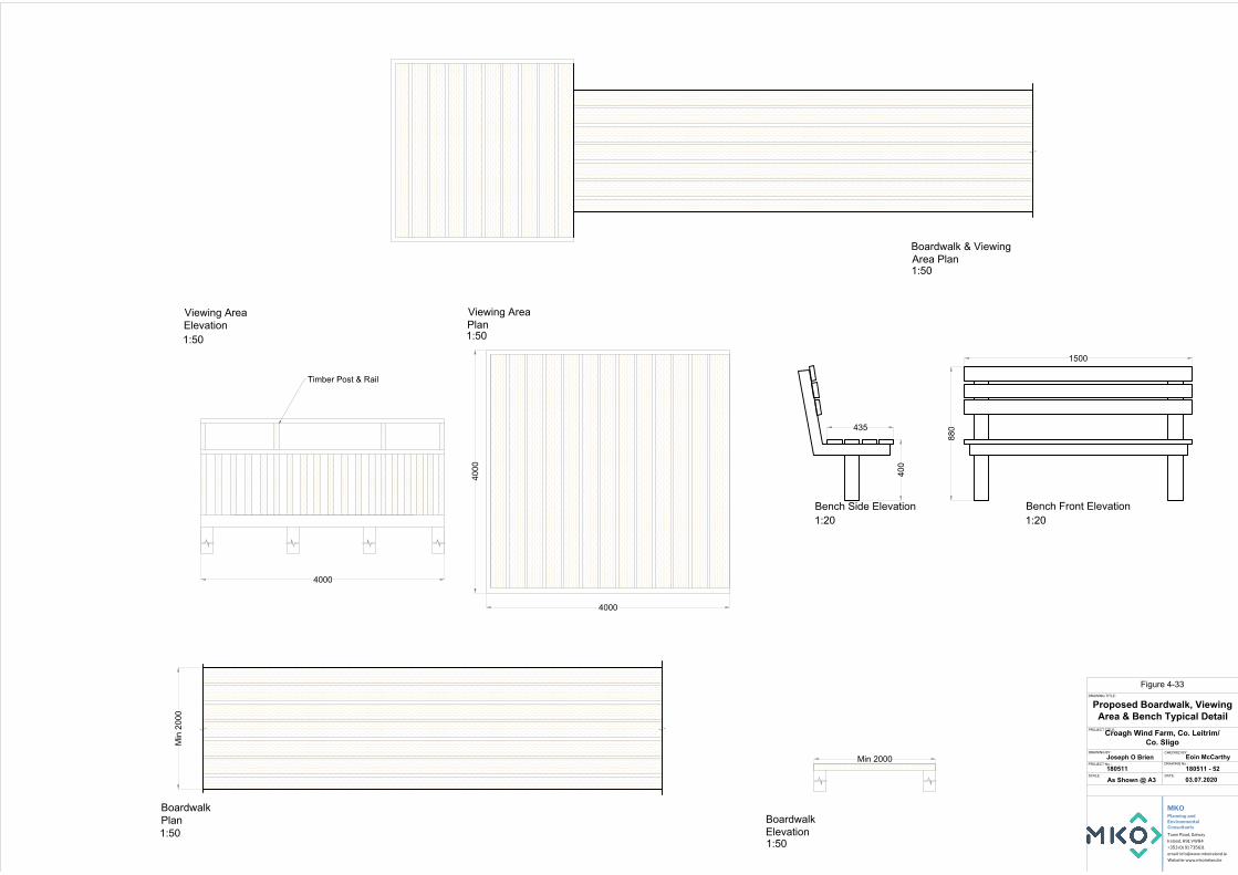
Min
200
0
4000
4000
4000
Min 2000
880
1500
400
435
DRAWING TITLE:
PROJECT TITLE:
DRAWING BY: CHECKED BY:
DRAWING No.:
SCALE: DATE:
PROJECT No.:
03.07.2020180511 - 52180511
Eoin McCarthyJoseph O Brien
Croagh Wind Farm, Co. Leitrim/Co. Sligo
Planning andEnvironmentalConsultants
Tuam Road, Galway
Ireland, H91 VW84
+353 (0) 91 735611
email: [email protected]
Website: www.mkoireland.ie
MKO
As Shown @ A3
Proposed Boardwalk, ViewingArea & Bench Typical Detail
Timber Post & Rail
Viewing AreaElevation
Viewing AreaPlan
BoardwalkPlan Boardwalk
Elevation
Boardwalk & ViewingArea Plan
Bench Front ElevationBench Side Elevation1:20
1:501:50
1:50 1:50
1:50
1:20
Figure 4-33

Proposed Croagh Wind Farm Development
Environmental Impact Assessment Report
EIAR – 2020.07.06 – 180511 – F
4-26
Entry point signage will be provided at various locations, where recreation users could enter the site, all at points on the marked walkways. The entry point information boards will clearly indicate each of the marked trails on a map, as well as outlining the distance, suitability and length of each trail. The signage will also indicate the principles of ‘Leave No Trace’. Waypoint map information signage indicating the location of the sign in the context of the overall site will be provided at five locations across the site, which will indicate to users “You Are Here” and outline the options available to them for continuing through the recreation area and provide information in relation to wind energy and the flora and fauna present along the walkways and within the local area. Waypoint direction signage will be provided at all junctions or at least at every one kilometre along the trails as reassurance waymarkers, to indicate the recommended direction of travel and distance to trail end and return distance to trailhead and will be colour coded to indicate the marked trail(s) on the route being followed. Elevation drawings of the proposed typical signage is shown on Figure 4-34.
4.6.2 Further Potential
The proposed recreation and amenity proposals outlined above form part of the Proposed Development, and will be provided subject to planning permission being granted. It is acknowledged that any investment in the creation of recreation and amenity proposals on the site of the Proposed Development will have to be matched by an ongoing commitment from the wind farm developer to maintain the recreation amenities once they are put in place. The amenity proposals which have been included as part of the Proposed Development can operate as standalone destination amenity walks, however, they would also facilitate and augment any future amenity proposals which may be brought forward in the wider area in the future.
The site is very well placed within the wider recreational area with the existing Miners Way very close to the site. Coillte is already active in this area with Sligo & Leitrim County Councils and we propose that the project support the development of the wider area which could be uncovered as part of a wider regional strategy.
4.7 Site Drainage
4.7.1 Introduction
The drainage design for the Proposed Development has been prepared by Hydro Environmental Services Ltd. (HES), and by the firm’s principal, Mr. Michael Gill. The protection of the watercourses within and surrounding the site, and downstream catchments that they feed is of utmost importance in considering the most appropriate drainage proposals for the site of the Proposed Development. The Proposed Development’s drainage design has therefore been proposed specifically with the intention of having no negative impact on the water quality of the site and its associated rivers and lakes, and consequently no impact on downstream catchments and ecological ecosystems. No routes of any natural drainage features will be altered as part of the Proposed Development and turbine locations and associated new roadways were originally selected to avoid natural watercourses, and existing roads are to be used wherever possible. There will be no direct discharges to any natural watercourses, with all drainage waters being dispersed as overland flows. All discharges from the proposed works areas will be made over vegetation filters at an appropriate distance from natural watercourses. Buffer zones of 100m and 50m around rivers and streams, respectively, have been used to inform the layout of the Proposed Development.
4.7.2 Existing Drainage Features
The routes of any natural drainage features will not be altered as part of the Proposed Development. Turbine locations have been selected to avoid natural watercourses. Up to 9 no. new watercourse crossings and 16 no. potential crossing upgrades will be required as part of the Proposed Development. One new crossing would be required along the alternative construction access road.

Amenity Area
xxxxxxxxxxxxxxxxxxxxxxxxxxxxxxxxxxxxxxxxxxxxxxxxxxxxxxxxxxxxxxxxxxxxxxxxxxxxxxxxxxxxxxxxxxxxxxxxxxxxxxxxxxxxxxxxxxxxxxxxxxxxxxxxxxxxxxxxxxxxxxxxxxxxxxxxxxxxxxxxxxxxxxxxxxxxxxxxxxxxxxxxxxxxxxxxxxxxxxxxxxxxxxxxxxxxxxxxxxxxxxxxxxxxxxxxxxxxxxxxxxxxxxxxxxxxxxxxxxxxxxxxxxxxxxxxxxxxxxxxxxxxxxxxxxxxxxxxxxxxxxxxxxxxxxxxxxxxxxxxxxxxxxxxxxxxxxxx
xxxxxxxxxxxxxxxxxxxxxxxxxxxxxxxxxxxxxxxxxxxxxxxxxxxxxxxxxxxxxxxxxxxxxxxxxxxxxxxxxxxxxxxxxxxxxxxxxxxxxxxxxxxxxxxxxxxxxxxxxxxxxxxxxxxxxxxxxxxxxxxxxxxxxxxxxxxxxxxxxxxxxxxxxxxxxxxxxxxxxxxxxxxxxxxxxxxxxxxxxxxxxxxxxxxxxxxxxxxxxxxxxxxxxxxxxxxxxxxxxxxxxxxxxxxxxxxxxxxxxxxxxxxxxxxxxxxxxxxxxxxxxxxxxxxxxxxxxxxxxxxxxxxxxxxxxxxxxxxxxxxxxxxxxxxxxxxx
xxxxxxxxxxxxxxxxxxxxxxxxxxxxxxxxxxxxxxxxxxxxxxxxxxxxxxxxxxxxxxxxxxxxxxxxxxxxxxxxxxxxxxxxxxxxxxxxxxxxxxxxxxxxxxxxxxxxxxxxxxxxxxxxxxxxxxxxxxxxxxxxxxxxxxxxxxxxxxxxxxxxxxxxxxxxxxxxxxxxxxxxxxxxxxxxxxxxxxxxxxxxxxxxxxxxxxxxxxxxxxxxxxxxxxxxxxxxxxxxxxxxxxxxxxxxxxxxxxxxxxxxxxxxxxxxxxxxxxxxxxxxxxxxxxxxxxxxxxxxxxxxxxxxxxxxxxxxxxxxxxxxxxxxxxxxxxxx
Area Mapxxxxxxxxxxxxxxxxxxxxxxxxxxxxxxxxxxxxxxxxxxxxxxxxxxxxxxxxxxxxxxxxxxxxxxxxxxxxxxxxxxxxxxxxxxxxxxxxxxxxxxxxxxxxxxxxxxxxxxxxxxxxxxxxxxxxxxxxxxxxxxxxxxxxxxxxxxxxxxxxxxxxxxxxxxxxxxxxxxxxxxxxxxxxxxxxxxxxxxxxxxxxxxxxxxxxxxxxxxxxxxxxxxxxxxxxxxxxxxxxxxxxxxxxxxxxxxxxxxxxxxxxxxxxxxxxxxxxxxxxxxxxxxxxxxxxxxxxxxxxxxxxxxxxxxxxxxxxxxxxxxxxxxxxxxxxxxxx
xxxxxxxxxxxxxxxxxxxxxxxxxxxxxxxxxxxxxxxxxxxxxxxxxxxxxxxxxxxxxxxxxxxxxxxxxxxxxxxxxxxxxxxxxxxxxxxxxxxxxxxxxxxxxxxxxxxxxxxxxxxxxxxxxxxxxxxxxxxxxxxxxxxxxxxxxxxxxxxxxxxxxxxxxxxxxxxxxxxxxxxxxxxxxxxxxxxxxxxxxxxxxxxxxxxxxxxxxxxxxxxxxxxxxxxxxxxxxxxxxxxxxxxxxxxxxxxxxxxxxxxxxxxxxxxxxxxxxxxxxxxxxxxxxxxxxxxxxxxxxxxxxxxxxxxxxxxxxxxxxxxxxxxxxxxxxxxx
Walkway 1
Walkway 2
2400
188 600 600 600
1800
1800
188 600 600
600
300
1200
Amenity Signage TypicalDetail
DRAWING TITLE:
PROJECT TITLE:
1 :20 @A3 03.07.2020180511
Joseph O Brien Eoin McCarthy
Croagh Wind Farm, Co. Leitrim/Co. Sligo
DRAWING BY: CHECKED BY:
DRAWING No.:
SCALE: DATE:
PROJECT No.:180511 - 53
Signage Type C - Way Point Direction Signage
Signage Type A - Waypoint Map Signage Signage Type B - Entry Point Signage
NoteFor illustrative purposes onlyexact details to be confirmed
Planning andEnvironmentalConsultants
Tuam Road, Galway
Ireland, H91 VW84
+353 (0) 91 735611
email: [email protected]
Website: www.mkoireland.ie
MKO
Figure 4-34

Proposed Croagh Wind Farm Development
Environmental Impact Assessment Report
EIAR – 2020.07.06 – 180511 – F
4-27
There will be no direct discharges to natural watercourses. All discharges from the proposed works areas or from interceptor drains will be made over vegetated ground at an appropriate distance from natural watercourse and lakes. Buffer zones around the existing natural drainage features have informed the layout of the Proposed Development and are indicated on the drainage design drawings.
Where artificial drains are currently in place in the vicinity of proposed works areas, these drains may have to be diverted around the proposed works areas to minimise the amount of water in the vicinity of works areas. Where it may not be possible to divert artificial drains around proposed work areas, the drains will be blocked to ensure sediment laden water from the works areas has no direct route to other watercourses. Where drains have to be blocked, the blocking will only take place after an alternative drainage system to handle the same water has been put in place.
Existing artificial drains in the vicinity of existing site roads will be maintained in their present location where possible. If it is expected that these artificial drains will receive drainage water from works areas, check dams will be added (as specified below) to control flows and sediment loads in these existing artificial drains. If road widening or improvement works are necessary along the existing roads, where possible, the works will take place on the opposite side of the road to the drain.
4.7.3 Drainage Design Principles
Drainage water from any works areas of the site of the Proposed Development will not be directed to any natural watercourses within the site. Two distinct methods will be employed to manage drainage water within the site. The first method involves keeping clean water clean by avoiding disturbance to natural drainage features, minimising any works in or around artificial drainage features, and diverting clean surface water flow around excavations and construction areas. The second method involves collecting any drainage waters from works areas within the site that might carry silt or sediment, to allow attenuation and settlement prior to controlled diffuse release.
The drainage design is intended to maximise erosion control, which is more effective than having to control sediment during high rainfall. Such a system also requires less maintenance. The area of exposed ground will be minimised. The drainage measures will prevent runoff from entering the works areas of the site from adjacent ground, to minimise the volume of sediment-laden water that has to be managed. Discoloured run-off from any construction area will be isolated from natural clean run-off.
The proposed wind farm drainage process flow is presented in Figure 4-35 below.

Proposed Croagh Wind Farm Development
Environmental Impact Assessment Report
EIAR – 2020.07.06 – 180511 – F
4-28
Figure 4-35 Proposed Wind Farm Drainage Process Flow
4.7.4 References
The drainage design has been prepared based on experience of the project team of other wind farm sites in peat-dominated environments, and the number of best practice guidance documents referred to in the References section of the EIAR.
4.7.5 Drainage Design
A detailed drainage design for the Proposed Development, incorporating all principles and measures outlined in this drainage design description, has been prepared, and is included in Appendix 4-5 of this EIAR. The drainage design employs the various measures further described below.
4.7.5.1 Interceptor Drains
Interceptor drains will be installed upgradient of any works areas to collect surface flow runoff and prevent it reaching excavations and construction areas of the site where it might otherwise have come into contact with exposed surfaces and picked up silt and sediment. The drains will be used to divert upslope runoff around the works area to a location where it can be redistributed over the ground surface as sheet flow. This will minimise the volume of potentially silty runoff to be managed within the construction area.
The interceptor drains will be installed in advance of any main construction works commencing. The material excavated to make the drain will be compacted on the downslope edge of the drain to form a diversion dike. On completion of the construction phase works, it is envisaged that the majority of the interceptor drains could be removed. At that stage, there will be no open excavations or large areas of exposed ground that are likely to give rise to large volumes of potentially silt-laden run off. Any areas in which works were carried out to construct roads, turbine bases or hardstands, will have been built up

Proposed Croagh Wind Farm Development
Environmental Impact Assessment Report
EIAR – 2020.07.06 – 180511 – F
4-29
with large grade hardcore, which even when compacted in place, will retain sufficient void space to allow water to infiltrate the subsurface of these constructed areas. It is not anticipated that roadways or other installed site infrastructure will intercept ground-conveyed surface water runoff to any significant extent that would result in scouring or over-topping or spill over. Where the drains are to be removed, they will be backfilled with the material from the diversion dike. Interceptor drains may have to be retained in certain locations, for example where roadways are to be installed on slopes, to prevent the roadways acting of conduits for water that might infiltrate the roadway sub-base. In these cases, interceptor drains would be maintained in localised areas along the roadway with culverts under the roadway, which would allow the intercepted water to be discharged to vegetation filters downgradient of the roadway. Similarly, in localised hollows where water is likely to be funnelled at greater concentrations than on broader slopes, interceptor drains, and culverts may be left in situ following construction.
The velocity of flow in the interceptor will be controlled by check dams (see Section 4.7.5.3 below), which will be installed at regular intervals along the drains to ensure flow in the channel is non-erosive. On steeper sections where erosion risks are greater, a geotextile membrane will be added to the channel.
Interceptor drains will be installed horizontally across slopes to run in parallel with the natural contour line of the slope. Intercepted water will travel along the interceptor drains to areas downgradient of works areas, where the drain will terminate at a level spreader (see Section 4.7.5.4 below). Across the entire length of the interceptor drains, the design elevation of the water surface along the route of the drains will not be lower than the design elevation of the water surface in the outlet at the level spreader.
4.7.5.2 Swales
Drainage swales are shallow drains that will be used to intercept and collect run off from construction areas of the site during the construction phase. Drainage swales will remain in place to collect runoff from roads and hardstanding areas of the proposed development during the operational phase. A swale is an excavated drainage channel located along the downgradient perimeter of construction areas, used to collect and carry any potentially sediment-laden runoff to a sediment-trapping facility and stabilised outlet. Swales are proven to be most effective when a dike is installed on the downhill side. They are similar in design to interceptor drains and collector drains described above.
Drainage swales will be installed downgradient of any works areas to collect surface flow runoff where it might have come into contact with exposed surfaces and picked up silt and sediment. Swales will intercept the potentially silt-laden water from the excavations and construction areas of the site and prevent it reaching natural watercourses.
Drainage swales will be installed in advance of any main construction works commencing. The material excavated to make the swale will be compacted on the downslope edge of the drain to form a diversion dike.
4.7.5.3 Check Dams
The velocity of flow in the interceptor drains and drainage swales, particularly on sloped sections of the channel, will be controlled by check dams, which will be installed at regular intervals along the drains to ensure flow in the swale is non-erosive. Check dams will also be installed in some existing artificial drainage channels that will receive waters from works areas of the site.
Check dams will restrict flow velocity, minimise channel erosion and promote sedimentation behind the dam. The check dams will be installed as the interceptor drains are being excavated.
The proposed check dams will be made up of straw bales or stone, or a combination of both depending on the size of the drainage swale it is being installed in. Where straw bales are to be used,

Proposed Croagh Wind Farm Development
Environmental Impact Assessment Report
EIAR – 2020.07.06 – 180511 – F
4-30
they will be secured to the bottom of the drainage swale with stakes. Clean 4-6 inch stone will be built up on either side and over the straw bale to a maximum height of 600mm over the bottom of the interceptor drain. In smaller channels, a stone check dam will be installed and pressed down into place in the bottom of the drainage swale with the bucket of an excavator.
The check dams will be installed at regular intervals along the interceptor drains to ensure the bottom elevation of the upper check dam is at the same level as the top elevation of the next down-gradient check dam in the drain. The centre of the check dam will be approximately 150mm lower than the edges to allow excess water to overtop the dam in flood conditions rather than cause upstream flooding or scouring around the dams.
Check dams will not be used in any natural watercourses, only artificial drainage channels and interceptor drains. The check dams will be left in place at the end of the construction phase to limit erosive linear flow in the drainage swales during extreme rainfall events.
Check dams are designed to reduce velocity and control erosion and are not specifically designed or intended to trap sediment, although sediment is likely to build up. If necessary, any excess sediment build up behind the dams will be removed. For this reason, check dams will be inspected and maintained regularly to insure adequate performance. Maintenance checks will also ensure the centre elevation of the dam remains lower than the sides of the dam.
4.7.5.4 Level Spreader
A level spreader will be constructed at the end of each interceptor drain to convert concentrated flows in the drain, into diffuse sheet flow on areas of vegetated ground. The levels spreaders will be located downgradient of any proposed works areas in locations where they are not likely to contribute further to water ingress to construction areas of the site.
The water carried in interceptor drains will not have come in contact with works areas of the site, and therefore should be free of silt and sediment. The level spreaders will distribute clean drainage water onto vegetated areas where the water will not be reconcentrated into a flow channel immediately below the point of discharge. The discharge point will be on level or only very gently sloping ground rather than on a steep slope so as to prevent erosion.
The slope in the channel leading into the spreader will be less than or equal to 1%. The slope downgradient of the spreader onto which the water will dissipate will have a grade of less than 6%. The availability of slopes with a grade of 6% or less will determine the locations of level spreaders. If a slope grade of less than 6% is not available in the immediate area downgradient of a works area at the end of a diversion drain, a piped slope drain (see Section 4.7.5.5 below) will be used to transfer the water to a suitable location.
The spreader lip over which the water will spill will be made of a concrete kerb, wooden board, pipe, or other similar piece of material that can create a level edge similar in effect to a weir. The spreader will be level across the top and bottom to prevent channelised flow leaving the spreader or ponding occurring behind the spreader. The top of the spreader lip will be 150mm above the ground behind it. The length of the spreader will be a minimum of four metres and a maximum length of 25 metres, with the actual length of each spreader to be determined by the size of the contributing catchment, slope and ground conditions.
Clean four-inch stone can be placed on the outside of the spreader lip and pressed into the ground mechanically to further dissipate the flow leaving the level spreader over a larger area.

Proposed Croagh Wind Farm Development
Environmental Impact Assessment Report
EIAR – 2020.07.06 – 180511 – F
4-31
4.7.5.5 Piped Slope Drains
Piped slope drains will be used to convey surface runoff from diversion drains safely down slopes to flat areas without causing erosion. Once the runoff reaches the flat areas it will be reconverted to diffuse sheet flow. Level spreaders will only be established on slopes of less than 6% in grade. Piped slope drains will be used to transfer water away from areas where slopes are too steep to use level spreaders.
The piped slope drains will be semi-rigid corrugated pipes with a stabilised entrance and a rock apron at the outlet to trap sediment and dissipate the energy of the water. The base of drains leading into the top of the piped slope drain will be compacted and concavely formed to channel the water into the corrugated pipe. The entrance at the top of the pipe will be stabilised with sandbags if necessary. The pipe will be anchored in place by staking at approximately 3-4 metre intervals or by weighing down with compacted soil. The bottom of the pipe will be placed on a slope with a grade of less than 1% for a length of 1.5 metres, before outflowing onto a rock apron.
The rock apron at the outlet will consist of 6-inch stone to a depth equal to the diameter of the pipe, a length six times the diameter of the pipe. The width of the rock apron will be three times the diameter of the pipe where the pipe opens onto the apron and will fan out to six times the diameter of the pipe over its length.
Piped slope drains will only remain in place for the duration of the construction phase of the Proposed Development. On completion of the works, the pipes and rock aprons will be removed, and all channels backfilled with the material that was originally excavated from them.
Piped slope drains will be inspected weekly and following rainfall events. Inlet and outlets will be checked for sediment accumulation and blockages. Stake anchors or fill over the pipe will be checked for settlement, cracking and stability. Any seepage holes where pipe emerges from drain at the top of the pipe will be repaired promptly.
4.7.5.6 Vegetation Filters
Vegetation filters are the existing vegetated areas of land that will be used to accept surface water runoff from upgradient areas. The selection of suitable areas to use as vegetation filters will be determined by the size of the contributing catchment, slope and ground conditions.
Vegetation filters will carry outflow from the level spreaders as overland sheet flow, removing any suspended solids and discharging to the groundwater system by diffuse infiltration.
Vegetation filters will not be used in isolation for waters that are likely to have higher silt loadings. In such cases, silt-bearing water will already have passed through stilling ponds prior to diffuse discharge to the vegetation filters via a level spreader.
4.7.5.7 Stilling Ponds
Stilling ponds will be used to attenuate runoff from works areas of the site of the Proposed Development during the construction phase and will remain in place to handle runoff from roads and hardstanding areas of the proposed development during the operational phase. The purpose of the stilling ponds is to intercept runoff potentially laden with sediment and to reduce the amount of sediment leaving the disturbed area by reducing runoff velocity. Reducing runoff velocity will allow larger particles to settle out in the stilling ponds, before the run-off water is redistributed as diffuse sheet flow in filter strips downgradient of any works areas.
Stilling ponds will be excavated/constructed at each required location as two separate ponds in sequence, a primary pond and a secondary pond. The points at which water enters and exits the stilling ponds will be stabilised with rock aprons, which will trap sediment, dissipate the energy of the water
Proposed Croagh Wind Farm Development
Environmental Impact Assessment Report
EIAR – 2020.07.06 – 180511 – F
4-32
flowing through the stilling pond system, and prevent erosion. The primary stilling pond will reduce the velocity of flows to less than 0.5 metres per second to allow settlement of silt to occur. Water will then pass from the primary pond to the secondary pond via another rock apron. The secondary stilling pond will reduce the velocity of flows to less than 0.3 metres per second. Water will flow out of the secondary stilling pond through a stone dam, partially wrapped in geo-textile membrane, which will control flow velocities and trap any sediment that has not settled out.
Water will flow by gravity through the stilling pond system. The stilling ponds will be sized according to the size of the area they will be receiving water from but will be sufficiently large to accommodate peak flows storm events. The stilling ponds will be dimensioned so that the length to width ratio will be greater than 2:1, where the length is the distance between the inlet and the outlet. Where ground conditions allow, stilling ponds will be constructed in a wedge shape, with the inlet located at the narrow end of the wedge. Each stilling pond will be a minimum of 1-1.5 metres in depth. Deeper ponds will be used to minimise the excavation area needed for the required volume.
The embankment that forms the sloped sides of the stilling ponds will be stabilised with vegetated turves, which will have been removed during the excavation of the stilling ponds area.
Stilling ponds will be located towards the end of swales, close to where the water will be reconverted to diffuse sheet flow. Upon exiting the stilling pond system, water will be immediately reconverted to diffuse flow via a fan-shaped rock apron if there is adequate space and ground conditions allow. Otherwise, a swale will be used to carry water exiting the stilling pond system to a level spreader to reconvert the flow to diffuse sheet flow.
A water level indicator such as a staff gauge will be installed in each stilling pond with marks to identify when sediment is at 10% of the stilling pond capacity. Sediment will be cleaned out of the still pond when it exceeds 10% of pond capacity. Stilling ponds will be inspected weekly and following rainfall events. Inlet and outlets will be checked for sediment accumulation and anything else that might interfere with flows.
4.7.5.8 Siltbuster
A “siltbuster” or similar equivalent piece of equipment will be available to filter any water pumped out of excavation areas if necessary, prior to its discharge to stilling ponds or swales.
Siltbusters are mobile silt traps that can remove fine particles from water using a proven technology and hydraulic design in a rugged unit. The mobile units are specifically designed for use on construction sites.
The unit stills the incoming water/solids mix and routes it upwards between a set of inclined plates for separation. Fine particles settle onto the plates and slide down to the base for collection, whilst treated water flows to an outlet weir after passing below a scum board to retain any floating material. The inclined plates dramatically increase the effective settling area of the unit giving it a very small footprint on site and making it highly mobile. Figure 4-36 below shows an illustrative diagram of the Siltbuster.
The Siltbuster units are now considered best practice for the management of dirty water pumped from construction sites. The UK Environment Agency and the Scottish Environmental Protection Agency have all recommended/specified the use of Siltbuster units on construction projects.

Proposed Croagh Wind Farm Development
Environmental Impact Assessment Report
EIAR – 2020.07.06 – 180511 – F
4-33
Figure 4-36 Siltbuster (Source: https://www.siltbuster.co.uk/sb_prod/siltbuster-fb50-settlement-unit/)
4.7.5.9 Silt Bags
Dewatering silt bags allow the flow of water through them while trapping any silt or sediment suspended in the water. The silt bags provide a passive non-mechanical method of removing any remaining silt contained in the potentially silt-laden water collected from works areas within the site.
Dewatering silt bags are an additional drainage measure that can be used downgradient of the stilling ponds at the end of the drainage swale channels and will be located, wherever it is deemed appropriate, throughout the site. The water will flow, via a pipe, from the stilling ponds into the silt bag. The silt bag will allow the water to flow through the geotextile fabric and will trap any of the finer silt and sediment remaining in the water after it has gone through the previous drainage measures. The dewatering silt bags will ensure that there will be no loss of peaty silt into the stream.
The dewatering silt bag that will be used will be approximately 3 metres in width by 4.5 metres (see Plate 4-5 and Plate 4-6 below) in length and will be capable of trapping approximately four tonnes of silt. The dewatering silt bag, when full, will be removed from site by a waste contractor with the necessary waste collection permit, who will then transport the silt bag to an appropriate, fully licensed waste facility.

Proposed Croagh Wind Farm Development
Environmental Impact Assessment Report
EIAR – 2020.07.06 – 180511 – F
4-34
Plate 4-3 Silt Bag with water being pumped through Plate 4-4 Silt bag under inspection
4.7.5.10 Sedimats
Sediment entrapment mats, consisting of coir or jute matting, will be placed at the outlet of the silt bag to provide further treatment of the water outfall from the silt bag. Sedimats will be secured to the ground surface using stakes/pegs. The sedimat will extend to the full width of the outfall to ensure all water passes through this additional treatment measure.
4.7.5.11 Culverts All new proposed culverts and proposed culvert upgrades will be suitably sized for the expected peak flows in the watercourse.
Some culverts may be installed to manage drainage waters from works areas of the proposed development, particularly where the waters have to be taken from one side of an existing roadway to the other for discharge. The size of culverts will be influenced by the depth of the track or road sub-base. In some cases, two or more smaller diameter culverts may be used where this depth is limited, though this will be avoided as they will have a higher associated risk of blockage than a single, larger pipe. In all cases, culverts will be oversized to allow mammals to pass through the culvert.
Culverts will be installed with a minimum internal gradient of 1% (1 in 100). Smaller culverts will have a smooth internal surface. Larger culverts may have corrugated surfaces which will trap silt and contribute to the stream ecosystem. Depending on the management of water on the downstream side of the culvert, large stone may be used to interrupt the flow of water. This will help dissipate its energy and help prevent problems of erosion. Smaller water crossings will simply consist of an appropriately sized pipe buried in the sub-base of the road at the necessary invert level to ensure ponding or pooling doesn’t occur above or below the culvert and water can continue to flow as necessary.
All culverts will be inspected regularly to ensure they are not blocked by debris, vegetation or any other material that may impede conveyance.
4.7.5.12 Silt Fences
Silt fences will be installed as an additional water protection measure around existing watercourses in certain locations, particularly where works are proposed within the 50-metre buffer zone of a stream or 100m buffer zone of a lake, which is inevitable where existing roads in proximity to watercourses are to be upgraded as part of the proposed development. These areas include around existing culverts, around the headwaters of watercourses, and the proposed locations are indicated on the detailed drainage design drawings included in Appendix 4-5.
Silt fences will be installed as single, double or a series of triple silt fences, depending on the space available and the anticipated sediment loading. The silt fence designs follow the technical guidance document ‘Control of Water Pollution from Linear Construction Projects’ published by CIRIA (Ciria, No. C648, 1996). Up to three silt fences may be deployed in series.

Proposed Croagh Wind Farm Development
Environmental Impact Assessment Report
EIAR – 2020.07.06 – 180511 – F
4-35
All silt fencing will be formed using Terrastop Premium or equivalent silt fence product.
Site fences will be inspected regularly to ensure water is continuing to flow through the fabric, and the fence is not coming under strain from water backing up behind it.
4.7.6 Forestry Felling Drainage Measures Tree felling to facilitate the Proposed Development will not be undertaken simultaneously with construction groundworks. Keyhole felling to facilitate construction works will take place prior to groundworks commencing.
Before the commencement of any felling works, an Environmental Clerk of Works (ECoW) shall be appointed to oversee the keyhole and extraction works. The ECoW shall be experienced and competent, and shall have the following functions and operate their record using a Schedule of Works Operation Record (SOWOR), as proposed in the planning application:
Attend the site for the setup period when drainage protection works are being installed and be present on site during the remainder of the forestry keyhole felling works.
Prior to the commencement of works, review and agree the positioning by the Operator of the required Aquatic Buffer Zones (ABZs), silt traps, silt fencing (see below), water crossings and onsite storage facilities for fuel, oil and chemicals (see further below).
Be responsible for preparing and delivering the Environmental Tool Box Talk (TBT) to all relevant parties involved in site operations, prior to the commencement of the works.
Conduct daily and weekly inspections of all water protection measures and visually assess their integrity and effectiveness in accordance with Section 3.4 (Monitoring and Recording) and Appendix 3 (Site Monitoring Form (Visual Inspections)) of the Forestry & FPM Requirements.
Take representative photographs showing the progress of operation onsite, and the integrity and effectiveness of the water protection measures.
Collect water samples for analysis by a 3rd party accredited laboratory, adhering to the following requirements:
o Surface water samples shall be collected upstream and downstream of the keyhole felling site at suitable sampling locations.
o Sampling shall be taken from the stream / riverbank, with no in-stream access permitted.
o The following minimum analytical suite shall be used: pH, EC, TSS, BOD, Total P, Ortho-P, Total N, and Ammonia.
Review of operator’s records for plant inspections, evidence of contamination and leaks, and drainage checks made after extreme weather conditions.
Prepare and maintain a contingency plan. Suspend work where potential risk to water from siltation and pollution is identified, or
where operational methods and mitigation measures are not specified or agreed. Prepare and maintain a Water Protection Measure Register. This document is to be
updated weekly by the ECoW.
All relevant measures set out in the Forestry & Freshwater Pearl Mussel Requirements, Forestry & Water Quality Guidelines, Forest Harvesting & the Environment Guidelines and the Forest Protection Guidelines will apply. To protect watercourses, the following measures will be adhered to during all keyhole/tree felling activities.
Works will be overseen by an ECoW as described above. The extent of all necessary tree felling will be identified and demarcated with markings
on the ground in advance of any felling commencing. All roads and culverts will be inspected prior to any machinery being brought on site to
commence the felling operation. No tracking of vehicles through watercourses will occur. Vehicles will only use existing road infrastructure and established watercourse crossings.

Proposed Croagh Wind Farm Development
Environmental Impact Assessment Report
EIAR – 2020.07.06 – 180511 – F
4-36
Existing drains that drain an area to be felled towards surface watercourses will be blocked, and temporary silt traps (ie. check dam / silt fence) will be constructed to ensure collection of all silt within felling areas. These temporary silt traps will be cleaned out and backfilled once felling works are complete. This ensures there is no residual collected silt remaining in blocked drains after felling works are completed. No direct discharge of such drains to watercourses will occur from within felling areas.
New collector drains and sediment traps will be installed during ground preparation to intercept water upgradient of felling areas and divert it away. Collector drains will be excavated at an acute angle to the contour (0.3%-3% gradient), to minimise flow velocities.
All silt traps will be sited outside of buffer zones and have no direct outflow into the aquatic zone. Machine access will be maintained to enable the accumulated sediment to be excavated. Sediment will be carefully disposed of away from all aquatic zones.
All new collector drains will taper out before entering the aquatic buffer zone to ensures the discharging water gently fans out over the buffer zone before entering the aquatic zone.
Machine combinations will be chosen which are most suitable for ground conditions at the time of felling, and which will minimise soils disturbance;
Mechanised operations will be suspended during and immediately after heavy rainfall. Where brash is required to form brash mats, it is to be laid out at harvesting stage to
prevent soil disturbance by machine movement. Brash which has not been pushed into the soil may be moved within the site to facilitate
the creation of mats in more demanding locations. Felling of trees will be pointed directionally away from watercourses. Felling will be planned to minimise the number of machine passes in any one area. Extraction routes, and hence brash mats, will be aligned parallel to the ground contours
where possible. Harvested timber will be stacked in dry areas, and outside any 50-metre watercourse
buffer zone. Straw bales and check dams to be emplaced on the down gradient side of timber storage sites.
Branches, logs or debris will not be allowed to build up in aquatic zones. All such material will be removed when harvesting operations have been completed but removing of natural debris deflectors will be avoided.
4.7.7 Borrow Pit Drainage
While surface water will be contained in the borrow pits area, the design proposal is to control the level of water in the borrow pit area by creating a single point outlet from the basin-like area that will ensure the water does not overtop the pit area. Run-off from the proposed borrow pit area will be controlled via a single outlet that will be installed at the edge of the borrow pit. The single outfall point will be constructed to manage runoff from the borrow pit and its immediate surrounds. Interceptor drains will already have been installed upgradient of the borrow pit area before any extraction begins.
During the construction phase of the project, it will be necessary to keep the borrow pit area free of standing water while rock is still being extracted. This will be achieved by using a mobile pump, which will pump water into the same series of drains, settlement ponds and level spreader, which will receive the water from the single outlet.
4.7.8 Floating Road Drainage
Where sections of floating road are to be installed, cross drains will be installed beneath the road construction corridor to maintain existing clean water drainage paths. Large surface water drainage pipes will be placed to from the cross-drains below the level of the proposed road sub-base. These drainage pipes will be extended each side of the proposed road and cable trench construction corridor, along the paths of the existing drains.

Proposed Croagh Wind Farm Development
Environmental Impact Assessment Report
EIAR – 2020.07.06 – 180511 – F
4-37
With the exception of the installation of cross drains under the floating road corridor, minimal additional drainage will be installed to run parallel to the roads, in order to maintain the natural hydrology of the peatland areas over which the roads will be floated.
4.7.9 Cable Trench Drainage
Cable trenches are typically developed in short sections, thereby minimising the amount of ground disturbed at any one time and minimising the potential for drainage runoff to pick up silt or suspended solids. Each short section of trench is excavated, ducting installed and bedded, and backfilled with the appropriate materials, before work on the next section commences.
To efficiently control drainage runoff from cable trench works areas, excavated material is stored on the upgradient side of the trench. Should any rainfall cause runoff from the excavated material, the material is contained in the downgradient cable trench. Excess subsoil is removed from the cable trench works area immediately upon excavation, and in the case of the Proposed Development, would be transported to one of the on-site borrow pits or used for landscaping and reinstatements of other areas elsewhere on site.
On steeper slopes, silt fences, as detailed in Section 4.7.5.12, above, will be installed temporarily downgradient of the cable trench works area, or on the downhill slope below where excavated material is being temporarily stored to control run-off.
4.7.10 Site and Drainage Management
4.7.10.1 Preparative Site Drainage Management
All materials and equipment necessary to implement the drainage measures outlined above, will be brought on-site in advance of any works commencing. An adequate number of straw bales, clean stone, terram, stakes, etc will be kept on site at all times to implement the drainage design measures as necessary. The drainage measures outlined in the above will be installed prior to, or at the same time as the works they are intended to drain.
4.7.10.2 Pre-emptive Site Drainage Management
The works programme for the groundworks part of the construction phase of the Proposed Development will also take account of weather forecasts, and predicted rainfall in particular. Large excavations, large movements of overburden or large-scale overburden or soil stripping will be suspended or scaled back if heavy rain is forecast. The extent to which works will be scaled back or suspended will relate directly to the amount of rainfall forecast.
4.7.10.3 Reactive Site Drainage Management
The final drainage design prepared for the Proposed Development prior to commencement of construction will provide for reactive management of drainage measures. The effectiveness of drainage measures designed to minimise runoff entering works areas and capture and treat potentially silt-laden water from the works areas, will be monitored continuously by the ECoW or supervising hydrologist on-site. The ECoW or supervising hydrologist will respond to changing weather, ground or drainage conditions on the ground as the project proceeds, to ensure the effectiveness of the drainage design is maintained. This may require the installation of additional check dams, interceptor drains, or swales as deemed necessary on-site. The drainage design may have to be modified on the ground as necessary, and the modifications will draw on the various features outlined above in whatever combinations are deemed to be most appropriate to the situation on the ground at a particular time.

Proposed Croagh Wind Farm Development
Environmental Impact Assessment Report
EIAR – 2020.07.06 – 180511 – F
4-38
In the event that works are giving rise to siltation of watercourses, the ECoW or supervising hydrologist will stop all works in the immediate area around where the siltation is evident. The source of the siltation will be identified and additional drainage measures such as those outlined above will be installed in advance of works recommencing.
4.7.11 Drainage Maintenance
An inspection and maintenance plan for the drainage system onsite will be prepared in advance of commencement of any works on the Proposed Development. Regular inspections of all installed drainage features will be necessary, especially after heavy rainfall, to check for blockages, and ensure there is no build-up of standing water at parts of the systems where it is not intended. The inspection of the drainage system will be the responsibility of the ECoW or the supervising hydrologist.
If necessary, any excess sediment build up behind check dams will be removed. For this reason, check dams will be inspected and maintained weekly during the construction phase of the project to insure adequate performance. Maintenance checks will also ensure the centre elevation of the dam remains lower than the sides of the dam.
Check dams will also be inspected weekly during the construction phase of the Proposed Development and following rainfall events to ensure the structure of the dam is still effective in controlling flow. Any scouring around the edges of the check dams or overtopping of the dam in normal flow conditions will be rectified be reinforcement of the check dam.
Drainage swales will be regularly inspected for evidence of erosion along the length of the swale. If any evidence of erosion is detected, additional check dams will be installed to limit the velocity of flow in the channel and reduce the likelihood of erosion occurring in the future.
A water level indicator such as a simple staff gauge or level marker will be installed in each silt trap with marks to identify when sediment is at 50% of the trap’s capacity. Sediment will be cleaned out of the silt trap when it exceeds 50% of trap capacity. Silt traps will be inspected weekly during the construction phase of the Proposed Development and following rainfall events. Inlet and outlets will be checked for sediment accumulation and anything else that might interfere with flows.
The frequency of drainage system inspections will be reduced following completion of the construction phase of the Proposed Development. Weekly inspections during the construction phase will be reduced to monthly, bi-monthly and eventually quarterly inspections during the operational phase up until the site has revegetated and the natural silt controls regenerate. The frequency will be increased or decreased depending on the effectiveness of the measures in place and the amount of remedial action required in any given period.
4.8 Construction Phasing and Timing It is estimated that the construction phase of the Proposed Development will take approximately 12-18 months from starting on site to the commissioning of the electrical system. In the interest of breeding birds, construction will not commence during the Breeding Bird season from April to July inclusive. Construction may commence at any stage from August onwards to the end of March, so that construction activities are ongoing by the time the next breeding bird season comes around and can continue throughout the next breeding season.
4.8.1 Construction Sequencing
The construction phase can be broken down into three main phases, 1) civil engineering works - 10 months, 2) electrical works - 6 months, and 3) turbine erection and commissioning - 8 months. The main task items under each of the three phases are outlined below.

Proposed Croagh Wind Farm Development
Environmental Impact Assessment Report
EIAR – 2020.07.06 – 180511 – F
4-39
Civil Engineering Works
Create new entrance(s) and hardcore existing entrances (where required). Clearfelling of forestry (as outlined in Section 4.3.10) Construct new site roads (permanent and temporary), drainage ditches and culverts. Clear and hardcore area for temporary site offices. Install same. Construct remaining new site roads and hard-standings and crane pads. Construct the substation, control buildings and groundworks for the substation
compound. Excavate/pile for turbine bases where required. Store soil/peat locally for backfilling
and re-use. Place blinding concrete to turbine bases. Fix reinforcing steel and anchorage system for tower section. Construct shuttering. Fix any ducts etc. to be cast in. Pour concrete bases. Cure concrete. Remove shutters after 1-2 days.
Electrical Works
Construct bases/plinths for transformer. Excavate trenches for site cables, lay cables and backfill. Provide ducts at road
crossings. Install external electrical equipment at substations Install transformer at compound. Erect stock proof and palisade fencing around substation area. Install internal collector network and communication cabling. Construct grid connection.
Turbine Erection and Commissioning
Backfill tower foundations and cover with suitable material. Erect towers, nacelles and blades. Complete electrical installation. Install anemometry masts and decommission and remove existing mast. Commission and test turbines. Complete site works, reinstate site. Remove temporary site offices. Provide any gates, landscaping, signs etc. which may
be required.
The phasing and scheduling of the main construction task items are outlined in Figure 4-37 below, where 1st January has been selected as an arbitrary start date for construction activities.

Proposed Croagh Wind Farm Development
Environmental Impact Assessment Report
EIAR – 2020.07.06 – 180511 – F
4-40
Figure 4-37 Indicative Construction Schedule
4.8.2 Construction Phase Monitoring and Oversight
The requirement for a Construction and Environmental Management Plan (CEMP) to be prepared in advance of any construction works commencing on any wind farm site and submitted for agreement to the Planning Authority is now well-established. The proposed procedures for the implementation of the mitigation measures outlined in such a CEMP and their effectiveness and completion is typically audited by way of a Construction and Environmental Management Plan Audit Report. The CEMP Audit Report effectively lists all mitigation measures prescribed in any of the planning documentation and all conditions attached to the grant of planning permission and allows them to be audited on a systematic and regular basis. The first assessment is a simply Yes/No question, has the mitigation measure been employed on-site or not? Following confirmation that the mitigation measure has been implemented, the effectiveness of the mitigation measures has to be the subject of regular review and audit during the full construction stage of the project. If some remedial actions are needed to improve the effectiveness of the mitigation measure, then these are notified to the site staff immediately during the audit site visit, and in writing by way of the circulation of the audit report. Depending on the importance and urgency of rectifying the issue, the construction site manager is given a timeframe by when the remedial works need to be completed.
A Construction Environmental Management Plan (CEMP) has been prepared for the Proposed Development and is included in Appendix 4-4 of this EIAR. The CEMP includes details of drainage, peat and overburden management, waste management etc, and describes how the above-mentioned Audit Report will function and be presented. In the event planning permission is granted for the Proposed Development, the CEMP will be updated prior to the commencement of the development, to address the requirements of any relevant planning conditions, including any additional mitigation measures which are conditioned and will be submitted to the Planning Authority for written approval.
The on-site construction staff will be responsible for implementing the mitigation measures specified in the EIAR and compiled in the Audit Report. Their implementation will be overseen by the ECoW or supervising hydrogeologists, environmental scientists, ecologists or geotechnical engineers, depending on who is best placed to advise on the implementation. The system of auditing referred to above ensures that the mitigation measures are maintained for the duration of the construction phase, and into the operational phase where necessary.

Proposed Croagh Wind Farm Development
Environmental Impact Assessment Report
EIAR – 2020.07.06 – 180511 – F
4-41
4.9 Construction Methodologies
4.9.1 Turbine Foundations
Each of the turbines to be erected on site will have a reinforced concrete base. Overburden will be stripped off the foundation area to a suitable formation using a 360° excavator and will be removed to the onsite borrow pit or one of the peat repositories. A five-metre-wide working area will be required around each turbine base, with the sides of the excavated areas sloped sufficiently to ensure that slippage does not occur. Material excavated to create the working area will be stored locally for later reuse in backfilling the working area around the turbine foundation. The excavated material will be sealed using the back of the excavator bucket to ensure no water is trapped within the material and it will be surrounded by silt fences to ensure sediment-laden run-off does not occur.
The formation material will have to be approved by an engineer as meeting the turbine manufacturer’s requirements. If the formation level is reached at a depth greater than the depth of the foundation, the ground level will be raised with clause 804 or similar hardcore material, compacted in 250 millimetres (mm) layers, with sufficient compacted effort (i.e. compacted with seven passes using 12 tonne roller). Drainage measures will be installed to protect the formation by forming an interceptor drain around the perimeter of the base which will outfall out at the lowest point level spreader or settlement pond.
An embankment approximately 600 mm high will be constructed around the perimeter of each turbine base and a fence will be erected to prevent construction traffic from driving into the excavated hole and to demarcate the working area. All necessary health and safety signage will be erected to warn of deep excavations etc. Access to and from excavated bases will be formed by excavating a pedestrian walkway to 1:12 grade.
There will be a minimum of 100 mm of blinding concrete laid on the formation material positioned using concrete skip and 360° excavator to protect ground formation and to give a safe working platform.
The anchor cage is delivered to site in 2 or more parts depending on the turbine type. A 360° excavator with suitable approved lifting equipment will be used to unload sections of the anchor cage and reinforcing steel. The anchor cage is positioned in the middle of the turbine base and is assembled accordingly. When the anchor cage is in final position it is checked and levelled by using an appropriate instrument. The anchor cage is positioned 250mm – 300mm from formation level by use of adjustable legs. Reinforcement bars are then placed around the anchor cage, first radial bars, then concentric bars, shear bars and finally the superior group of bars. Earthing material is attached during the steel foundation build up. The level of the anchor cage will be checked again prior to the concrete pour and during the concrete pour
Formwork to concrete bases will be propped/supported sufficiently so as to prevent failure. Concrete for bases will be poured using a concrete pump. Each base will be poured in three stages. Stage 1 will see the concrete being poured and vibrated in the centre of the anchor cage to bring the concrete up to the required level inside the cage. Stage 2 will see the centre of the steel foundation being poured and vibrated to the required level. Stage 3 will see the remaining concrete being poured around the steel foundation to bring it up to the required finished level. After a period of time when the concrete has set sufficiently the top surface of the concrete surface is to be finished with a power float.
Once the base has sufficient curing time it will be filled with suitable fill up to existing ground level. The working area around the perimeter of the foundation will be backfilled with the original material that was excavated.

Proposed Croagh Wind Farm Development
Environmental Impact Assessment Report
EIAR – 2020.07.06 – 180511 – F
4-42
4.9.2 Site Roads and Crane Pad Areas
Site roads will be constructed to each turbine base and at each base a crane hard standing will be constructed to the turbine manufacturer’s specifications and the largest predicted area has been assessed in this EIAR. Tracked excavators will carry out excavation for roads with appropriate equipment attached. The excavations shall follow a logical route working away from the borrow pit locations. Excavated material will be transported back to the borrow pits in haul trucks. A two to three-metre-wide working area will be required around each hardstanding area, with the sides of the excavated areas sloped sufficiently to ensure that slippage does not occur. Material excavated to create the working area will be stored locally for later reuse in backfilling the working area around the turbine foundation. The excavated material will be covered with polythene sheets and surrounded by silt fences to ensure sediment-laden run-off does not occur.
When the formation layer has been reached, stone from the on-site borrow pit shall be placed to form the road foundation. In the event of large clay deposits being encountered in sections of road, a geotextile layer will be required at sub-base level. The sub grade will be compacted with the use of a roller. The final wearing course will not be provided until all bases have been poured. This prevents damage to the wearing course due to stone and concrete trucks movements. The road will be upgraded prior to the arrival of the first turbine. All roads will be maintained for the duration of the operation of the Proposed Development.
4.9.3 Proposed Clear-span Watercourse Crossings
It is proposed to construct clear-span watercourse crossings along the access roads to Turbine No. 1 and Turbine No. 10 using corrugate metal arches. The locations of these crossings are shown as Proposed New Watercourse Crossing No. 1 and No. 2 on the layout drawings included in Appendix 4-1 of this EIAR. It is proposed that these crossings will be constructed using a corrugated metal arch and appropriate backfill.
The typical construction methodology for the installation of a corrugated metal arch and stone clear-span bridge is presented below:
The access road on the approach to the watercourse will be completed to a formation level which is suitable for the passing of plant and equipment required for the installation of the watercourse crossing.
The foundation will consist of concrete panels which will be installed on a concrete lean mix foundation to provide a suitable base. The base will be excavated to rock or competent ground with a mechanical excavator with the foundation formed in-situ using a semi-dry concrete lean mix. The base will be excavated along the stream bank with no instream works required.
The bottom plate of the arch will be bolted to the foundation on both sides of the stream. The top section of the culvert will be bolted together and lifted into position and bolted to the two bottom sections. This sequence will continue until the full length of culvert is in position.
Once the arch is in position stone backfill will be placed and compacted against the culvert up to the required level above the foundations. A concrete beam will then be shuttered, fixed and poured along the two shoulders of the steel culvert.
When the concrete beams are cured the filling and compaction of the road will be completed.
The design drawings for the 2 No. proposed, corrugate metal arch clear-span watercourse crossings are shown in Figure 4-38 and Figure 4-39.
A further four new water course crossings will be required as part of the proposed development. The locations of these crossings are shown as Proposed New Watercourse Crossing No. 3 to No. 7 on the

Proposed Croagh Wind Farm Development
Environmental Impact Assessment Report
EIAR – 2020.07.06 – 180511 – F
4-43
layout drawings in Appendix 4-1. It is proposed that these crossings will be constructed using bottomless, pre-cast concrete structures.
The typical construction methodology for the installation of a pre-cast concrete clear-span bridge is presented below:
�The access road on the approach to the watercourse will be completed to a formation level which is suitable for the passing of plant and equipment required for the installation of the watercourse crossing.
�All drainage measures along the proposed road will be installed in advance of the works. �The abutment will consist of concrete panels which will be installed on a concrete lean
mix foundation to provide a suitable base. The base will be excavated to rock or competent ground with a mechanical excavator with the foundation formed in-situ using a semi-dry concrete lean mix. The base will be excavated along the stream bank with no instream works required.
�Access to the opposite side of the river for excavation and foundation installation will require the installation of pre-cast concrete slab across the river to provide temporary access for the excavator.
�All pre-cast concrete panels and slabs/beams will be installed using a crane which will be set up on the bank of the watercourse and will be lifted into place from the bank with no contact with the watercourse.
�A concrete deck will be poured over the beams/slabs which span across the river. This will be shuttered, sealed and water tested before concrete pouring can commence.
A typical design drawing of a pre-cast concrete, clear span crossing is shown in Figure 4-40.
The watercourse crossings will be constructed to the specifications of the OPW bridge design guidelines ’Construction, Replacement or Alteration of Bridges and Culverts - A Guide to Applying for Consent under Section 50 of the Arterial Drainage Act, 1945’, and in consultation with Inland Fisheries Ireland. Abutments will be constructed from precast units combined with in-situ foundations, placed within an acceptable backfill material.
4.9.4 Onsite Electricity Substation and Control Building
Once tree felling as described in Section 4.3.10, above, is completed, the onsite substation will be constructed by the following methodology:
The area of the onsite substation will be marked out using ranging rods or wooden posts and the soil and overburden stripped and removed to nearby temporary storage area for later use in landscaping. Any excess material will be sent to one of the on-site peat repositories or the proposed borrow pit, for reinstatement purposes.
The dimensions of the onsite substation area have been designed to meet the requirements of the ESB and the necessary equipment to safely and efficiently operate the proposed wind farm;
A control building will be built within the onsite substation compound; The foundations will be excavated down to the level indicated by the designer and
appropriately shuttered reinforced concrete will be laid over it. An anti-bleeding admixture will be included in the concrete mix;
The block work walls will be built up from the footings to DPC level and the floor slab constructed, having first located any ducts or trenches required by the follow on mechanical and electrical contractors;
The block work will then be raised to wall plate level and the gables & internal partition walls formed. Scaffold will be erected around the outside of the building for this operation;
The roof slabs will be lifted into position using an adequately sized mobile crane;

SOFFIT LEVEL
ROAD LEVEL
EXISTINGGROUND
EXISTINGGROUND
FOUNDATION LEVEL
BRIDGE CROSS SECTIONScale 1:100
STRUCTURALFILL MATERIAL
STRUCTURALFILL MATERIAL
STREAM BEDLEVEL
7400 APPROX.
3500
APP
RO
X.
CORRUGATED METALARCH
IN-SITU CONCRETEFOUNDATION
IN-SITU CONCRETE FOUNDATIONILLUSTRATED (FOUNDATION TYPE
[E.G. PILED, SPREAD FOOTING]T.B.C. AT DETAILED DESIGN STAGE)
STRUCTURALFILL MATERIAL
VARIATION INSTREAM BANKTHROUGHSTRUCTURE
SOFFIT LEVEL
FOUNDATION LEVEL
FILL MATERIAL
7400 APPROX.
CORRUGATED METALARCH
LEGEND
STRUCTURAL FILL
BRIDGE STRUCTURE
EXISTING GROUND LEVEL
STREAM BANK
EMBANKMENT
ROAD
1000APPROX.
1000APPROX.
T1
EXACT BRIDGE DIMENSIONSTO BE CONFIRMEDFOLLOWING CONFIRMATORYGROUND INVESTIGATIONS
STREAM BANK
WINGWALLS
ARCH STRUCTURE
EMBANKMENT SLOPE
WINGWALLS
SITE ROADCUT EMBANKMENT SLOPE
T1
STREAM
FENCE
BARRIER/BERM
FENCE
BARRIER/BERM
ADROASITE R
ARCH STRUCTURE
FENCE
BARRIER/BERMEMBANKMENT SLOOPE
BARRIER/BERM
CUT EMBANKMENT
EXTENT OF EMBANKMENT TO ALLOWFORMATION ON SUITABLE SUBGRADE
EXTENT OF EARTHWORKS EXCAVATION
EXTENT OF EMBANKMENT TO ALLOWFORMATION ON SUITABLE SUBGRADE
EXTENT OF EMBANKMENT TO ALLOWFORMATION ON SUITABLE SUBGRADE
EXACT BRIDGE DIMENSIONSTO BE CONFIRMEDFOLLOWING CONFIRMATORYGROUND INVESTIGATIONS
19m APPRO
X.
LEGEND
ROAD
EMBANKMENT
STEAM
BRIDGE STRUCTURE
PROJECT
TITLE
DRAWING NUMBER
DRAWN BY
STATUSCHECKED AND APPROVED
REVISION
DATE
DATE
SCALEPAPER SIZE
ENGINEER CLIENT
Z:\Projects\Ireland\Croagh CROA\Drawings\CROA D002 Bridges\CROA D002.1.1 BridgesREV DATE DRAWN BY DETAILSCHECKED BYPlotted - 03/07/2020 14:13:07
The Hyde Building, The Park, Carrickmines, Dublin 18,D18VC44, IrelandE. [email protected]. +353 (0) 1 845 5031W. www.ionicconsulting.ie
Formerly known as WIND PROSPECT IRELAND
NOTES
0511-55
D
CROAGH WIND FARM
PROPOSED NEW WATERCOURSE CROSSING NO.1AS SHOWN
INFORMATION
A3M. BROWNE 26/07/2019
J. SHANAHAN 26/07/2019A 26.07.19 M.B. J.S. DRAFT ISSUE - FOR DISCUSSIONB 04.10.19 M.B. J.S. PLAN INCLUDED
C 01.11.19 M.B. J.S. CLIENT COMMENTS INCLUDEDD 03.07.20 M.B J.S LEGEND ADDED
BRIDGE PLANScale 1:500
N
S
W E

STRUCTURALFILL MATERIAL
STRUCTURALFILL MATERIAL
SOFFIT LEVEL
FOUNDATION LEVEL
STRUCTURALFILL MATERIAL
STREAM BED LEVEL
VARIATION INSTREAM BANKTHROUGHSTRUCTURE
EXISTINGGROUND
EXISTINGGROUND
1000APPROX.
1000APPROX.
7400 APPROX.3500
APP
RO
X.
T10ROAD LEVEL
SOFFIT LEVEL
FOUNDATION LEVEL
UCTURALMATERIAL
1000
7400 APPROX.3500
APP
RO
X.
LEGEND
STRUCTURAL FILL
BRIDGE STRUCTURE
EXISTING GROUND LEVEL
STREAM BANK
EMBANKMENT
ROAD
CORRUGATEDMETAL ARCH
IN-SITU CONCRETE FOUNDATIONILLUSTRATED (FOUNDATION TYPE
[E.G. PILED, SPREAD FOOTING]T.B.C. AT DETAILED DESIGN STAGE)
STREAM BANKEXACT BRIDGE DIMENSIONSTO BE CONFIRMEDFOLLOWING CONFIRMATORYGROUND INVESTIGATIONS
T
STREAM
STREAM FLOW
WINGWALLS ARCH STRUCTURE
EMBANKMENT SLOPE
WINGWALLS
SITE ROAD
CUT EMBANKMENT SLOPE
FENCE
BARRIER/BERM
T10
EXTENT OF EMBANKMENT TO ALLOWFORMATION ON SUITABLE SUBGRADE
EXTENT OF EMBANKMENT TO ALLOWFORMATION ON SUITABLE SUBGRADE
EXACT BRIDGE DIMENSIONSTO BE CONFIRMEDFOLLOWING CONFIRMATORYGROUND INVESTIGATIONS
LEGEND
ROAD
EMBANKMENT
STEAM
BRIDGE STRUCTURE
PROJECT
TITLE
DRAWING NUMBER
DRAWN BY
STATUSCHECKED AND APPROVED
REVISION
DATE
DATE
SCALEPAPER SIZE
ENGINEER CLIENT
Z:\Projects\Ireland\Croagh CROA\Drawings\CROA D002 Bridges\CROA D002.1.1 BridgesREV DATE DRAWN BY DETAILSCHECKED BYPlotted - 03/07/2020 14:17:07
The Hyde Building, The Park, Carrickmines, Dublin 18,D18VC44, IrelandE. [email protected]. +353 (0) 1 845 5031W. www.ionicconsulting.ie
Formerly known as WIND PROSPECT IRELAND
NOTES
0511-56
C
CROAGH WIND FARM
PROPOSED NEW WATERCOURSE CROSSING NO.2AS SHOWN
INFORMATION
A3M. BROWNE 01/10/2019
J. SHANAHAN 01/10/2019A 01.10.19 M.B. J.S. FIRST ISSUEB 01.11.19 M.B. J.S. CLIENT COMMENTS INCLUDED
C 03.07.20 M.B. J.S. LEGEND ADDED
BRIDGE CROSS SECTIONScale 1:100
BRIDGE PLANScale 1:500
N
S
W E

Proposed Croagh Wind Farm Development
Environmental Impact Assessment Report
EIAR – 2020.07.06 – 180511 – F
4-44
The timber roof trusses will then be lifted into position using a telescopic load all or mobile crane depending on site conditions. The roof trusses will then be felted, battened, tiled and sealed against the weather.
The electrical equipment will be installed and commissioned. Perimeter fencing will be erected. The construction and components of the substation are to ESB specifications.
4.9.5 Temporary Construction Compounds
The temporary construction compounds will be constructed as follows:
The area to be used as the compound will be marked out at the corners using ranging rods or timber posts. Drainage runs and associated settlement ponds will be installed around the perimeter;
The compound platform will be established using a similar technique as the construction of the substation platform discussed above;
A layer of geo-grid will be installed, and compacted layers of well graded granular material will be spread and lightly compacted to provide a hard area for site offices and storage containers;
Areas within the compound will be constructed as site roads and used as vehicle hardstandings during deliveries and for parking;
The compound will be fenced and secured with locked gates if necessary; and, Upon completion of the Proposed Development the temporary construction compound
will be decommissioned by backfilling the area with the material arising during excavation, landscaping with topsoil as required.
The car park that is proposed as part of the recreation and amenity facilities will be constructed in a similar manner to the proposed temporary construction compounds.
4.9.6 Grid Connection Cable Trench
The underground cabling (UGC) works will consist of the installation of ducts in an excavated trench to accommodate power cables, and a fibre communications cable to allow communications between the Croagh Wind Farm Substation and Garvagh Substation.
The UGC will either be a single circuit or a double circuit 38kV connection, in accordance with the requirements and specifications of ESB . The difference between the two connection types is the number of ducts, the number of cables and the width of the trench and associated joint bay chambers. A single circuit connection typically consists of 3 no. 110mm diameter HDPE power cable ducts and 1 no. 110mm diameter HDPE communications duct to be installed in an excavated trench, typically 600mm wide by 1,220mm deep. A double circuit connection typically consists of 6 no. 110mm diameter HDPE power cable ducts and 2 no. 110mm diameter HDPE communications duct to be installed in an excavated trench, typically 900mm wide by 1,220mm deep. For trench designs there will be variations on the design to adapt to service crossings and watercourse crossings.
The power cable ducts will accommodate the power cables and the communications duct(s) will accommodate a fibre cable(s) to allow communications between the Croagh Wind Farm substation and Garvagh Substation. The ducts will be installed, the trench reinstated in accordance with landowner or local authority specification, and then the electrical cabling/fibre cable is pulled through the installed ducts in approximately 650/750m sections. Construction methodologies to be implemented and materials to be used will ensure that the UGC is installed in accordance with the requirements and specifications of ESB.
The underground cable required to facilitate the grid connection will be laid beneath the surface of the site and/or public road using the following the methodology summarised below, and outlined in detail

1
1
Existing Ground
1
1
Proposed Road Surface Level
Embankment Fill
Water Level
Precast Concrete Structure
600
Stone Fill
DRAWING TITLE:
PROJECT TITLE:
DRAWING BY: CHECKED BY:
DRAWING No.:
SCALE: DATE:
PROJECT No.:
03.07.2020180511 - 57180511
Michael WatsonJoseph O Brien
Croagh Wind Farm, Co. Leitrim/Co. Sligo
Planning andEnvironmentalConsultants
Tuam Road, Galway
Ireland, H91 VW84
+353 (0) 91 735611
email: [email protected]
Website: www.mkoireland.ie
MKO
1:50 @ A3
Typical Pre-cast ConcreteClearspan Watercourse Crossing
Figure 4-40

Proposed Croagh Wind Farm Development
Environmental Impact Assessment Report
EIAR – 2020.07.06 – 180511 – F
4-45
in TLI Group’s Croagh Wind Farm 38kVGrid Connection – Construction Methodology included as Appendix 4-5 of this EIAR:
The Contractor, and their appointed Site Manager, will prepare a targeted Method Statement concisely outlining the construction methodology and incorporating all mitigation and control measures included within the planning application and accompanying reports and as required by planning conditions where relevant;
All existing underground services shall be identified on site prior to the commencement of construction works;
At watercourse crossings, the contractor will be required to adhere to the environmental control measures outlined within the planning application and accompanying reports, the final Construction Environmental Management Plan (CEMP) and best practice construction methodologies;
Where the cable route intersects with culverts, the culvert will remain in place (where possible) and the ducting will be installed either above or below the culvert to provide minimum separation distances in accordance with ESB specifications;
Traffic management measures will be implemented in accordance with those included in the Chapter 14 of this EIAR and a final Traffic Management Plan will be prepared and agreed with the local authority;
The excavated trench will be approximately 600/900mm in width and approximately 1220mm deep both within the public road network and within Coillte lands;
The base of the excavated trench will be lined with sand bedding to be imported to site from a local licensed supplier. The 110mm diameter HDPE cable ducting will be placed into the prepared trench, inspected and backfilled as per Figures 4 & 5;
Excavated material will be temporarily stockpiled onsite for re-use during reinstatement. Stockpiles will be restricted to less than 2m in height. Stockpiles will be located a minimum of 50m from surface water features and all stockpiling locations will be subject to approval by the Site Manager and Project Ecological Clerk of Works (ECoW);
Excavated material shall be reused to backfill the trench where appropriate and any surplus material will be transported to either the proposed onsite borrow pit or repository areas;
Any earthen (sod) banks to be excavated will be carefully opened with the surface sods being stored separately and maintained for use during reinstatement;
The excavated trench will be dewatered if required, from a sump installed within the low section of the opened trench. Where dewatering is required, silt laden water will be fully and appropriately attenuated, through silt bags, before being appropriately discharged to vegetation or surface water drainage feature (please refer to drainage design in the proposed development);
Where required, grass will be reinstated by either seeding or by replacing with grass turves;
No more than a 100 metre section of trench will be opened at any one time. The second 100 metres will only be excavated once the majority of reinstatement has been completed on the first;
The excavation, installation and reinstatement process will take on average of 1 no. day to complete a 100m section;
Where the cable is being installed in a roadway, temporary reinstatement may be provided to allow larger sections of road to be permanently reinstated together;
Following the installation of ducting, pulling the cable will take approximately 1 day between each joint bay, with the jointing of cables taking approximately 1-2 days.
4.9.6.1 Site Cable Trenching
The transformer in each turbine is connected to the substation through a network of buried electrical cables. The ground is trenched typically using a mechanical excavator. The top layer of soil is removed and saved so that it is replaced on completion. The cables will be bedded with suitable material. The cables will be laid at a depth that meets all national and international requirements, and will generally

Proposed Croagh Wind Farm Development
Environmental Impact Assessment Report
EIAR – 2020.07.06 – 180511 – F
4-46
be approximately 1.3m below ground level; a suitable marking tape is installed between the cables and the surface (see Plate 4-7below). On completion, the ground will be reinstated as previously described above. The route of the cable ducts will follow the access track to each turbine location, and are visible on the site layout drawings included as Appendix 4-1 of the EIAR.
Plate 4-5 Typical Cable Trench View
4.9.6.2 Existing Underground Services
In order to facilitate the installation of the proposed UGC, it may be necessary to relocate existing underground services such as water mains or existing cables. In advance of any construction activity, the contractor will undertake additional surveys of the proposed route to confirm the presence or otherwise of any services. If found to be present, the relevant service provider will be consulted with in order to determine the requirement for specific excavation or relocation methods and to schedule a suitable time to carry out works.
If existing low voltage underground cables are found be present, a trench will be excavated, and new ducting and cabling will be installed along the new alignment and connected to the network on either end. The trench will be backfilled with suitable material to the required specification. Warning strip and marking tape will be laid at various depths over the cables as required. Marker posts and plates will be installed at surface level to identify the new alignment of the underground cable, the underground cables will then be re-energised.
In the event that water mains are encountered the water supply will be turned off by the utility so work can commence on diverting the service. The section of existing pipe will be removed and will be replaced with a new pipe along the new alignment of the service. The works will be carried out in accordance with the utility standards.
4.9.6.3 Joint Bays
Joints Bays are to be provided approximately every 750m - 800m along the UGC route to facilitate the jointing of 2 no. lengths of UGC. The joint bays will be pre-cast concrete structures installed below finished ground level. The joint bay width varies between single and double circuits (2.03 – 2.7m). Joint Bays will be located in the non-load bearing strip of roadways insofar as possible.

Proposed Croagh Wind Farm Development
Environmental Impact Assessment Report
EIAR – 2020.07.06 – 180511 – F
4-47
In association with Joint Bays, Communication Chambers are required at every joint bay location to facilitate communication links between the Croagh Wind Farm substation and the existing Garvagh 110kV Substation. Earth Sheath Link Chambers are also required approximately every second joint bay along the cable route. Earth Sheath Links are used for earthing and bonding cable sheaths of underground power cables, installed in a flat formation, so that the circulating currents and induced voltages are eliminated or reduced. Earth Sheath Link Chambers and Communication Chambers are located in close proximity to Joint Bays. Earth Sheath Link Chambers and Communication Chambers will typically be pre-cast concrete structures with an access cover at finished surface level. The locations of the joint bays and chambers are shown on the site layout drawings in Appendix 4-1.
The precise siting of all Joint Bays, Earth Sheath Link Chambers and Communication Chambers within the planning corridor is subject to approval by ESBN.
4.9.6.4 Grid Connection Watercourse/Culvert Crossings
Nine watercourse crossing locations were identified along the cable route. All of the watercourse crossings identified are culverts and no bridge crossings have been identified. It is proposed to cross all watercourses using open trenching with either an undercrossing or an overcrossing, depending on the depth of the culvert. A schedule of the culverts identified and the proposed crossing method to be implemented is detailed in Appendix 4-6 of this EIAR and the locations are shown on the site layout drawings included in Appendix 4-1. Should an alternative methodology option be required for individual crossings during the construction process this will be agreed with the relevant authorities including prior to works commencing. The proposed culvert crossing methods are detailed in Figure 4-42 below, the number of ducts will vary between a single and double circuit connection.
Where the cable route intersects with existing watercourses, a detailed construction method statement will be prepared by the Contractor prior to the commencement of construction and is to be approved by the Local Authority and relevant environmental agencies as required.
Inland Fisheries Ireland have published guidelines relating to construction works along water bodies entitled “Requirements for the Protection of Fisheries Habitats during Construction and Development Works at River Sites”, and these guidelines will be adhered to during the construction of the proposed development.
4.9.6.5 Horizontal Direction Drilling
It is not currently proposed to implement Horizontal Directional Drilling (HDD) for any crossings. However, following confirmatory site investigations prior to construction it may be necessary to utilise HDD for some crossings.
Horizontal Direction Drilling (HDD) is a method of drilling under obstacles such as bridges, culverts, railways, water courses, etc. in order to install cable ducts under the obstacle. This method is employed where installing the ducts using standard installation methods is not possible. The proposed HDD methodology is as follows: -
A works area of circa .40 square metres will be fenced on both sides of a crossing The drilling rig and fluid handling units will be located on one side of the bridge and will
be stored on double bunded 0.5mm PVC bunds which will contain any fluid spills and storm water run-off.
Entry and exit pits (1m x 1m x 2m) will be excavated using an excavator, the excavated material will be temporarily stored within the works area and used for reinstatement or disposed of to a licensed facility.
A 1m x 1m x 2m steel box will be placed in each pit. This box will contain any drilling fluid returns from the borehole.

300
50
300
MIN
1880
300
MAX
300
MAX
DUCTS LAID IN CBGM B (CL 822)COMPACTED TO CL 813.10 AND TABLE 8/4OF TII SPECIFICATION FORROADWORKS (15N/MM²) LEGEND
110mm Ø HDPE
RED MARKER STRIP
YELLOW MARKERWARNING TAPE
EXISTING CULVERT / SERVICE(TO BE SUPPORTED DURINGTHE CROSSING) FINISHED GROUND /
ROAD LEVEL110mm Ø HDPECOMMUNICATION DUCT WITH12mm DIAMTER PULL ROPE
RED MARKER STRIP ORSTEEL PLATES
1000 1000 YELLOW MARKER WARNING TAPE
RAPID HARDENING WETCONCRETE GRADE C25/30BETWEEN CULVERT /SERVICE & PIPE DUCTING.
1:6 GRADIENT
SERVICEOD
SECTION A-ASCALE 1:50
EXISTINGCULVERT / SERVICE.DUCTS LAID IN CBGM B (CL 822)
COMPACTED TO CL 813.10 AND TABLE 8/4OF TII SPECIFICATION FORROADWORKS (15N/MM²)
1000 1000
SPLAY DUCTS INTO 2 HORIZONTALROW OF 4 DUCTS TO MINIMIZEEXCAVATION.
1:6 GRADIENT
POWER DUCT WITH12mm DIAMTER PULL ROPE
NOTES
1. This drawing is to be read in conjunction with all otherrelevant documentation.
2. Do not scale from this drawing use only printeddimensions.
3. All dimensions are in millimetres, all chainages, levelsand co-ordinates are in metres unless defined otherwise.
4. This drawing is to be read in conjunction with the projectHealth & Safety file for any identified potential risks.
5. No excavation shall commence until the contractor hasconsulted up to date services drawings and carried outan Electromagnetic Locator (EML) Scan.
6. Hand dig only within 500mm of existing services.7. If compacting CBGM B could cause damage to the
culvert / service below, use rapid hardening cementgrade C25/30 following engineers prior approval.
8. For standard trench cross section drawings andminimum horizontal separation to existing services, seeTLI-05649-213/214 (TREFOIL)and 05649-220 (FLAT).
9. Where depths exceed 3000mm to the top of duct thecontractor shall consult the cable system designengineer for phase spacing requirements.
10.For Watermain crossings, see 05649-218
RAPID HARDENING WETCONCRETE GRADE C25/30BETWEEN CULVERT /SERVICE & PIPE DUCTING.
SERVICEOD
PLAN VIEWSCALE 1:50
YELLOW MARKERWARNING TAPE
A393 STEELREINFORCEMENT MESH
FINISHED GROUND /ROAD LEVEL
38kV DOUBLE CIRCUIT DETAILS -2. SERVICE/CULVERT OVERCROSSING
EXISTINGCULVERT / SERVICE.
1:6 GRADIENT
SERVICEOD
SECTION C-CSCALE 1:50
EXISTINGCULVERT / SERVICE.DUCTS LAID IN CBGM B (CL 822)
COMPACTED TO CL 813.10 AND TABLE 8/4OF TII SPECIFICATION FORROADWORKS (15N/MM²)
SERVICEOD
PLAN VIEWSCALE 1:50
1:6 GRADIENT
CL804
A393 STEELREINFORCEMENT MESH.
8 No. STEEL PLATES &RED MARKER STRIPS
A393 STEEL REINFORCEMNET MESH
6mm GALVANISED STEEL PLATE
MIN BURIAL DEPTH450mm
8 No. STEELPLATES &RED MARKERSTRIPS
RED MARKER STRIP
INSTALL STEEL PLATES & MESH UNTIL DUCTS REACH STANDARD DEPTH INSTALL STEEL PLATES & MESH UNTIL DUCTS REACH STANDARD DEPTH
DUCTS LAID IN CBGM B (CL 822)COMPACTED TO CL 813.10 AND TABLE 8/4OF TII SPECIFICATION FORROADWORKS (15N/MM²)
38kV DOUBLE CIRCUIT DETAILS -1. SERVICE/CULVERT UNDERCROSSING
6575
50M
AX 3
00
EXISTING CULVERT/SERVICE.
ESBN APPROVED YELLOW WARNINGTAPE FOR WIDTH OF TRENCH
BACKFILL AND REINSTATE ASPER SPECIFICATION
FINISHED GROUND / ROAD LEVEL
SECTION B-BSCALE: NTS
A AA
MIN
300
75
50mm SEPARATION BETWEENEXISTING SERVICE AND CONCRETE
A393 STEEL REINFORCEMENT MESH FOR WIDTH OF TRENCH
RAPID HARDENING WETCONCRETE GRADE C25/30
RED MARKER STRIPS 4x200mm WIDE LINKED TO 4x200mm WIDE GALVANIZED STEEL PLATES
A = 110mm OUTER DIAMETER HDPE ESB APPROVED DUCT, SDR=17.6
A
75 75 75 150250
A AAA
75 75 75
885
MIN
*
EXISTING CULVERT / SERVICECROWN LEVEL OF CULVERT /SERVICE PIPE
* ALL EXISTING SERVICES WITH COVER LESSTHAN MIN. DIMENSIONS ABOVE SHALL BECROSSED BY UNDERCROSSING METHOD
1880
SECTION D-DSCALE: NTS
FINISHED GROUND / ROAD LEVEL
7530
0 M
AX
MIN
450
75
A = 110mm OUTER DIAMETER HDPE ESB APPROVED DUCT, SDR=17.6
A393 STEEL REINFORCEMENT MESH FOR WIDTH OF TRENCH
RAPID HARDENING WETCONCRETE GRADE C25/30
RED MARKER STRIPS 4x200mm WIDE LINKED TO 4x200mm WIDE GALVANIZED STEEL PLATES
ESBN APPROVED YELLOW WARNINGTAPE FOR WIDTH OF TRENCH BACKFILL AND REINSTATE AS
PER SPECIFICATION
65 EXISTING GROUNDA AAA
75 75 75 150
150
A AAAA AAA
150 75 75 75 250
1880
1880
SPLAY DUCTS INTO 2 HORIZONTALROW OF 4 DUCTS TO MINIMIZEEXCAVATION.
CROWN LEVEL OF CULVERT /SERVICE PIPE
I/R DATE DESCRIPTION
ISSUE/REVISION
00 29.08.19 Issued for Information
01 19.11.19 Issued for Planning
02 12.06.20 Issued for Planning
03 01.07.20 Issued for Planning
ISO
A1
594m
m x
841
mm
NOTES: -
CONSULTANTS
PROJECT NUMBER
SHEET TITLE
SHEET NUMBER
GROUP
LEGEND: -
PROJECT
CLIENT
Head OfficeBeenreigh, Abbeydorney, Tralee, Co. KerryIrelandTel: 00353 66 7135710
Regional OfficeBasepoint Business CentreStroudley Road, Basingstoke,Hampshire,RG24 8UP, UKTel: 00 44 1256406664
Croagh Wind Farm38kV Grid Connection
05-649
38kV Double Circuit -Service/Culvert Crossing Detail
05649-217(0511-73)Proj
ect M
anag
emen
t Ini
tials
:D
esig
ner:
Che
cked
:Ap
prov
ed:
CHSK
RG
See notes in drawing window

Proposed Croagh Wind Farm Development
Environmental Impact Assessment Report
EIAR – 2020.07.06 – 180511 – F
4-48
The drill bit will be set up by a surveyor, and the driller will push the drill string into the ground and will steer the bore path under the watercourse.
A surveyor will monitor drilling works to ensure that the modelled stresses and collapse pressures are not exceeded.
The drilled cuttings will be flushed back by drilling fluid to the steel box in the entry pit. Once the first pilot hole has been completed a hole-opener or back reamer will be fitted
in the exit pit and will pull a drill pipe back through the bore to the entry side. Once all bore holes have been completed, a towing assembly will be set up on the drill
and this will pull the ducting into the bore. The steel boxes will be removed, with the drilling fluid disposed of to a licensed facility. The ducts will be cleaned and proven and their installed location surveyed. The entry and exit pits will be reinstated to the specification of ESB Networks and the
landowner.
A joint bay or transition chamber will be installed on either side of the bridge following the horizontal directional drilling as per ESB requirements. The horizontal direction drilling method is illustrated in Figure 4-44 below.
Figure 4-44 Horizontal Directional Drilling Methodology
4.9.7 Proposed Demolition Works
As outline in Section 4.4.1.1 it is proposed to carry out partial demolition works on two agricultural buildings as part of the development of the proposed link road for turbine component and abnormal load deliveries. A single bay on the northern side of the storage shed will be demolished and the masonry wall will be reconstructed at the end of the adjacent bay. This detail is shown in Figure 4-26. A 6.9m length of the rear masonry wall of the livestock shed will be demolished and part of the gable sheeting will be removed. The central steel support structure will be relocated by one metre to increase the size of the opening at the rear of the livestock shed. This will be replaced with a corrugated, galvanised steel door. This detail is shown in Figure 4-28. The demolition will be carried out using the following methodology.
An inventory of the waste types that will be generated by the demolition works will be carried out.
Any equipment or miscellaneous materials within northern bay of the storage shed will be removed.
Removal of all fixtures and supporting structures. Removal of the roof sheeting over the northern bay of the storage shed and the
section of gable sheeting at the rear of the livestock shed. Demolition will be completed by way of a mechanical excavator which will remove
the structure and all associated groundworks. The demolition of the masonry wall structures will be carried out by a mechanical
excavator.

Proposed Croagh Wind Farm Development
Environmental Impact Assessment Report
EIAR – 2020.07.06 – 180511 – F
4-49
The majority of the waste generated by the demolition of the existing shed will consist of concrete rubble and stones from the existing wall structure, floor and foundations. This material will be segregated from all other waste components and sent by an authorised waste collector to an authorised waste recovery facility.
The remaining volume of waste material will not be large enough to warrant any further segregation therefore, all waste generated during the demolition of the building will be deposited into a single skip that will be brought by a waste collector to an appropriately authorised facility.
4.10 Operation The Proposed Development is expected to have a lifespan of approximately 30 years. Planning permission is being sought for a 30-year operation period commencing from the date of full operational commissioning of the wind farm. During the operational period, on a day-to-day basis the wind turbines will operate automatically, responding by means of anemometry equipment and control systems to changes in wind speed and direction.
The wind turbines will be connected together, and data relayed from the wind turbines to an off-site control centre. Each turbine will also be monitored off-site by the wind turbine supplier. The monitoring of turbine output, performance, wind speeds, and responses to any key alarms will be monitored at an off-site control centre 24-hours per day.
Each turbine will be subject to a routine maintenance programme involving a number of checks and changing of consumables, including oil changes. In addition, there will be a requirement for unscheduled maintenance, which could vary between resetting alarms to major component changes requiring a crane. Typically, maintenance traffic will consist of four-wheel drive vehicles or vans. The electricity substation and battery storage components and site tracks will also require periodic maintenance.
4.11 Decommissioning The wind turbines proposed as part of the Proposed Development are expected to have a lifespan of approximately 30 years. Following the end of their useful life, the wind turbines may be replaced with a new set of turbines, subject to planning permission being obtained, or the Proposed Development may be decommissioned fully. The onsite substation will remain in place as it will be under the ownership of the ESB and will form a permanent part of the national electricity grid.
Upon decommissioning of the Proposed Development, the wind turbines would be disassembled in reverse order to how they were erected. All above ground turbine components would be separated and removed off-site for recycling. Turbine foundations would remain in place underground and would be covered with earth and reseeded as appropriate. Leaving the turbine foundations in-situ is considered a more environmentally prudent option, as to remove that volume of reinforced concrete from the ground could result in significant environment nuisances such as noise, dust and/or vibration. Site roadways will be left in situ, for future forestry operations. The amenity and recreation infrastructure will also be left in-situ. Underground cables, including grid connection, will be removed and the ducting left in place. A decommissioning plan will be agreed with the local authorities three months prior to decommissioning the Proposed Development.

Proposed Croagh Wind Farm Development
Environmental Impact Assessment Report
EIAR – 2020.07.06 – 180511 – F
4-50
However, as noted in the Scottish Natural Heritage report (SNH) Research and Guidance on Restoration and Decommissioning of Onshore Wind Farms (SNH, 2013) reinstatement proposals for a wind farm are made approximately 30 years in advance, so within the lifespan of the wind farm, technological advances and preferred approaches to reinstatement are likely to change. According to the SNH guidance, it is therefore:
“best practice not to limit options too far in advance of actual decommissioning but to maintain informed flexibility until close to the end-of-life of the wind farm”.