Depicting shape features with directional strokes and spotlighting
8
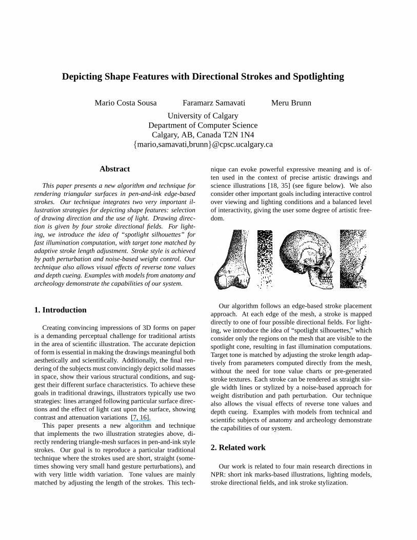
Depicting Shape Features with Directional Strokes and Spotlighting Mario Costa Sousa Faramarz Samavati Meru Brunn University of Calgary Department of Computer Science Calgary, AB, Canada T2N 1N4 {mario,samavati,brunn}@cpsc.ucalgary.ca Abstract This paper presents a new algorithm and technique for rendering triangular surfaces in pen-and-ink edge-based strokes. Our technique integrates two very important il- lustration strategies for depicting shape features: selection of drawing direction and the use of light. Drawing direc- tion is given by four stroke directional fields. For light- ing, we introduce the idea of “spotlight silhouettes” for fast illumination computation, with target tone matched by adaptive stroke length adjustment. Stroke style is achieved by path perturbation and noise-based weight control. Our technique also allows visual effects of reverse tone values and depth cueing. Examples with models from anatomy and archeology demonstrate the capabilities of our system. 1. Introduction Creating convincing impressions of 3D forms on paper is a demanding perceptual challenge for traditional artists in the area of scientific illustration. The accurate depiction of form is essential in making the drawings meaningful both aesthetically and scientifically. Additionally, the final ren- dering of the subjects must convincingly depict solid masses in space, show their various structural conditions, and sug- gest their different surface characteristics. To achieve these goals in traditional drawings, illustrators typically use two strategies: lines arranged following particular surface direc- tions and the effect of light cast upon the surface, showing contrast and attenuation variations [7, 16]. This paper presents a new algorithm and technique that implements the two illustration strategies above, di- rectly rendering triangle-mesh surfaces in pen-and-ink style strokes. Our goal is to reproduce a particular traditional technique where the strokes used are short, straight (some- times showing very small hand gesture perturbations), and with very little width variation. Tone values are mainly matched by adjusting the length of the strokes. This tech- nique can evoke powerful expressive meaning and is of- ten used in the context of precise artistic drawings and science illustrations [18, 35] (see figure below). We also consider other important goals including interactive control over viewing and lighting conditions and a balanced level of interactivity, giving the user some degree of artistic free- dom. Our algorithm follows an edge-based stroke placement approach. At each edge of the mesh, a stroke is mapped directly to one of four possible directional fields. For light- ing, we introduce the idea of “spotlight silhouettes,” which consider only the regions on the mesh that are visible to the spotlight cone, resulting in fast illumination computations. Target tone is matched by adjusting the stroke length adap- tively from parameters computed directly from the mesh, without the need for tone value charts or pre-generated stroke textures. Each stroke can be rendered as straight sin- gle width lines or stylized by a noise-based approach for weight distribution and path perturbation. Our technique also allows the visual effects of reverse tone values and depth cueing. Examples with models from technical and scientific subjects of anatomy and archeology demonstrate the capabilities of our system. 2. Related work Our work is related to four main research directions in NPR: short ink marks-based illustrations, lighting models, stroke directional fields, and ink stroke stylization.
-
Upload
independent -
Category
Documents
-
view
0 -
download
0
Transcript of Depicting shape features with directional strokes and spotlighting
Depicting Shape Features with Directional Strokes and Spotlighting
Mario Costa Sousa Faramarz Samavati Meru Brunn
University of CalgaryDepartment of Computer ScienceCalgary, AB, Canada T2N 1N4
{mario,samavati,brunn}@cpsc.ucalgary.ca
Abstract
This paper presents a new algorithm and technique forrendering triangular surfaces in pen-and-ink edge-basedstrokes. Our technique integrates two very important il-lustration strategies for depicting shape features: selectionof drawing direction and the use of light. Drawing direc-tion is given by four stroke directional fields. For light-ing, we introduce the idea of “spotlight silhouettes” forfast illumination computation, with target tone matched byadaptive stroke length adjustment. Stroke style is achievedby path perturbation and noise-based weight control. Ourtechnique also allows visual effects of reverse tone valuesand depth cueing. Examples with models from anatomy andarcheology demonstrate the capabilities of our system.
1. Introduction
Creating convincing impressions of 3D forms on paperis a demanding perceptual challenge for traditional artistsin the area of scientific illustration. The accurate depictionof form is essential in making the drawings meaningful bothaesthetically and scientifically. Additionally, the final ren-dering of the subjects must convincingly depict solid massesin space, show their various structural conditions, and sug-gest their different surface characteristics. To achieve thesegoals in traditional drawings, illustrators typically use twostrategies: lines arranged following particular surface direc-tions and the effect of light cast upon the surface, showingcontrast and attenuation variations [7, 16].
This paper presents a new algorithm and techniquethat implements the two illustration strategies above, di-rectly rendering triangle-mesh surfaces in pen-and-ink stylestrokes. Our goal is to reproduce a particular traditionaltechnique where the strokes used are short, straight (some-times showing very small hand gesture perturbations), andwith very little width variation. Tone values are mainlymatched by adjusting the length of the strokes. This tech-
nique can evoke powerful expressive meaning and is of-ten used in the context of precise artistic drawings andscience illustrations [18, 35] (see figure below). We alsoconsider other important goals including interactive controlover viewing and lighting conditions and a balanced levelof interactivity, giving the user some degree of artistic free-dom.
Our algorithm follows an edge-based stroke placementapproach. At each edge of the mesh, a stroke is mappeddirectly to one of four possible directional fields. For light-ing, we introduce the idea of “spotlight silhouettes,” whichconsider only the regions on the mesh that are visible to thespotlight cone, resulting in fast illumination computations.Target tone is matched by adjusting the stroke length adap-tively from parameters computed directly from the mesh,without the need for tone value charts or pre-generatedstroke textures. Each stroke can be rendered as straight sin-gle width lines or stylized by a noise-based approach forweight distribution and path perturbation. Our techniquealso allows the visual effects of reverse tone values anddepth cueing. Examples with models from technical andscientific subjects of anatomy and archeology demonstratethe capabilities of our system.
2. Related work
Our work is related to four main research directions inNPR: short ink marks-based illustrations, lighting models,stroke directional fields, and ink stroke stylization.
1) Short ink marks-based illustrations: Winkenbach andSalesin [34] introducedstroke textureswhich procedurallyaccumulate strokes for patterns made with short marks.Praun et al. [25] extended this approach introducingtonalart mapswhich organize pre-rendered strokes as a sequenceof mip-mapped images. Some researchers have focused onthe geometric relation between the stipple marks [3, 15]. Aparticle-based distribution approach was used by Deussenand Strothotte [4] to place marks for tree foliage render-ing. A voxel-based approach has been proposed by Lu etal. [19] with an interactive direct volume stippling illustra-tion system. Secord et al. [29] develop a fast probabilisticmethod that places small arbitrarily-shaped primitives, in-cluding stippling. More recently, Pastor et al. [23] presentan approach where stipple particles are attached to the sur-face of the model, using a point hierarchy to control thestipple shading density. In [32], a system is described forrendering large, detailed meshes, using extracted geomet-ric shape features to guide the placement of strokes on eachmesh edge.
We extended the work in [32] to include stroke direc-tional fields and the evaluation of “spotlight silhouettes” di-rectly at each edge in the model. All of these extensionsare placed into a new version of the edge-buffer data struc-ture [2]. Also, we match target tones by adaptively adjust-ing the stroke length directly at each edge. Our methodalso allows for efficient visualizations of tone value rever-sals across the model.
2) NPR lighting: Compared to photorealistic rendering al-gorithms, lighting in NPR does not generally attempt tosimulate or approximate a physical model of light-surfaceinteraction. Instead, the goal is often to extract additionalinformation from the scene to help generate a stylized ren-dering. Martin and Torres [20] use multiple interactively-placed diffuse or specularvirtual lights to generate silhou-ette outlines and shape lines for cartoon animation-stylerenderings of 3D objects. Akers et al. [1] interactively com-posite multiple differently-lit images of an object to repro-duce the artistic technique of using different lighting condi-tions for different feature areas of an object. Hall [12] intro-duces a technique to visualize the shape of precisely colored3D surfaces without color distortion from lighting. Goochet al. [8] (extended in [9]) introduce an NPR lighting modelthat mimics the artistic style of traditional technical illustra-tions. Hamel [13] presents a new lighting model, derivedfrom traditional scientific illustration principles, that allowsboth photorealistic and artistic illumination techniques suchas rim shadows, curvature shading and transparency.
Our approach is similar in principle to the idea presentedin [20]. In our work, we first extract all mesh regions visibleto the spotlight rays and then calculate the light intensity ateach edge in the edge-buffer. The reason we select a spot-light is because (1) it provides coverage of selective areas in
the model with (2) attenuated light intensity. Both aspectsare very useful to create different visualizations of the shapefeatures.
3) Directional strokes: In mesh-based NPR systems, thefocus has been mainly on estimating principal direction ofcurvature (usually at each mesh vertex) to guide the strokeplacement process [6, 14, 25, 27].
In our system we estimate four types of stroke directionalfields, providing alternate visualizations of shape features.We use two calculation methods. The first method estimatesthe principal directions of curvature at each vertex with sub-sequent edge-buffer updates. The second method estimatestwo directional fields directly at each edge by consideringthe normals of the two triangles adjacent to it.
4) Ink stroke stylization: Stroke stylization helps bothin evaluating surface shape and achieving expressive effecttypical of artistic drawings. Stroke textures [34] use slightperturbations of the stroke’s curvature, length, and directionto give a less mechanical look to pen-and-ink renderings.Kaplan et al. [17] vary line thickness of silhouette strokesbased on light intensity. Northrup and Markosian [22] allowthe user to specify a combination of various stylization suchas tapering, flaring, and wiggles to achieve a desired lookfor silhouette edge strokes. In [32], surface curvature met-rics are used to automatically adjust stroke thickness. Thestrokes are then drawn with different pen marking styles.
Our stroke stylizer combines path perturbation [28] witha new way of distributing specific weight patterns using Per-lin noise [24].
3. Illustration techniques
In this section, we briefly review two key principles oftraditional illustration used together for depicting shape fea-tures: the selection of drawing direction and the use of light;much more detailed studies can be found in a number oftexts [7, 11, 16, 35].
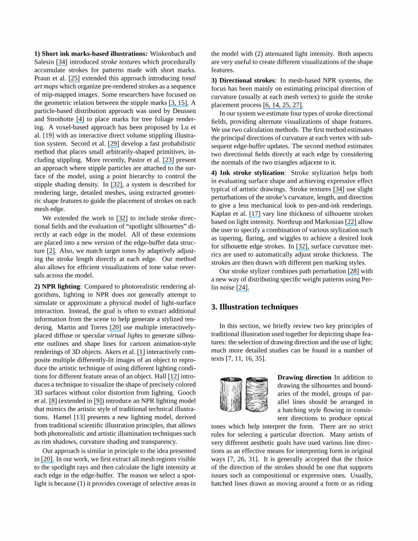
Drawing direction In addition todrawing the silhouettes and bound-aries of the model, groups of par-allel lines should be arranged ina hatching style flowing in consis-tent directions to produce optical
tones which help interpret the form. There are no strictrules for selecting a particular direction. Many artists ofvery different aesthetic goals have used various line direc-tions as an effective means for interpreting form in originalways [7, 26, 31]. It is generally accepted that the choiceof the direction of the strokes should be one that supportsissues such as compositional or expressive ones. Usually,hatched lines drawn as moving around a form or as riding
upon its surface undulations tell us more about a shape’sform than lines that go in other directions on it. Therefore, acommon strategy is to establish two main directional fields,one orthogonal to the other. In the cylinder drawings [7](previous page), the lines of the left cylinder direct our eyesalong the length of the body suggesting a more forcefulmove in a direction, while those in the right cylinder movearound it, telling us a little more about its volume [7].
Light on form The placement of lines in particular direc-tions is not the only way to describe form. Light on form is avery important and complementary technique for conveyingshape features and overall form of subjects. Tone values cando more than establish local tones, build forms and suggestlight. They can help the artist to add expressiveness to thesubject [7, 11, 16]. Light not only can be made to explainand unify forms, it can provide important visual and expres-sive meanings. Without a study of the subject’s tonalities,important structural clues are missed. Traditional illustra-tion commonly tend to have a “dramatic” light source (i.e.light off to one side of the model), to experiment with tonevalue studies. Also, abrupt changes in value are used to sug-gest angular forms and gradual changes for rounded forms.
4. Algorithm overview
Our data structures and algorithms were selected to pro-vide interactive rates for visualization of complex meshes.For efficiency, our technique uses two stages: we sepa-rate the single-pass pre-processing from the user-adjustableinteractive controls over the final rendering. In the pre-processing phase, we construct an edge buffer [2] from themesh and simultaneously compute and store the four strokedirection fields at each edge (sec. 5). During run-time spot-light silhouettes are extracted and illumination values arecomputed at each edge (sec. 6). Strokes are then renderedfrom the direction and illumination values stored with eachedge. To match the target tones from the attenuated spot-lighting, the length of each stroke is adjusted proportionally,based on the stored intensity (sec. 6). Finally, the stroke isstylized with path perturbation and ink weight distribution,imparting a less uniform look to strokes rendered on regularmeshes (sec. 7).
5. Stroke directional fields
Based on the techniques of traditional illustration, weconsider two orthogonal directions for strokes (sec. 3).In order to achieve an efficient technique, these directionsare pre-computed and saved in the data structure. Conse-quently, in our case, the directions are associated with theedges of the 3D mesh.
The important problem is to determine the appropriatedirections from the given 3D mesh. Although there is noclear artistic rule for having a unique stroke direction, itis possible to find reasonable solutions that can depict theshape of the object. We consider two solutions.
Method 1: principal directions of curvature Principal di-rections of curvature are classical geometric measures thatcan visualize the local shape of the surface. The maximalcurvaturec1 and minimal curvaturec2 are called princi-pal curvatures, the associated tangent vectorse1 ande2 arecalled principal directions. Therefore, moving alonge1 pro-duces the highest and moving alonge2 causes the lowestvariation for the normal at the surface. These two directionsare mutually orthogonal to each other and form an orthonor-mal basis for the tangent space. Although there is a richtheory in differential geometry about curvature of differen-tiable surfaces, the resulting methods are not appropriatefor 3D meshes as non-differentiable surfaces. In contrast,methods from discrete differential geometry are preferredfor these kind of objects [5, 21, 33]. In this approach, prin-cipal curvatures and directions are estimated by evaluatingthe eigenvalues and eigenvectors of a3 × 3 matrix that isclosely related to the tensor of curvature. This matrix canbe estimated by difference of the normals at a vertex andits neighbors [5, 21, 33]. For an edge-based data structuresuch as the edge-buffer, it is beneficial if the directions areassigned directly to the edges. We use the average ofe1
at two adjacent vertices of the edge as the first direction ofthe edge. Analogously, the average ofe2 at two adjacentvertices is used as the second direction.
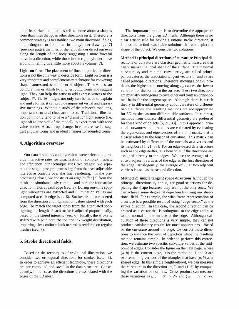
Method 2: simple tangent space directionsAlthough theprincipal directionse1 and e2 are good selections for de-picting the shape features, they are not the only ones. Wecan achieve some degree of depiction by using any direc-tional field. For example, the wire-frame representation ofa surface is a possible result of using “edge vector” as thestroke direction. In this case, the second direction can becreated as a vector that is orthogonal to the edge and alsoto the normal of the surface at the edge. Although cal-culation of these directions is very simple, they can notproduce satisfactory results for most applications. Basedon the curvature around the edge, we correct these direc-tions to enhance the level of depiction while the resultingmethod remains simple. In order to perform this correc-tion, we estimate two specific curvature values at the mid-point of edges. Consider the figure on the next page, where(a, b) is the current edge,0 is the midpoint,1 and 2 aretwo remaining vertices of the triangles that have(a, b) as ashared edge. In this simple neighborhood, we can measurethe curvature in the direction(a, b) and(1, 2) by comput-ing the variation of normals. Cross product can measurethese variations asξab = Na × Nb andξ12 = N1 × N2.
We pick the direction of the largest vector (ξab and ξ12)as the first direction denoted byf1. We estimateN0, thenormal vector at the “phantom” vertex 0 (midpoint of edgeab), by N0 = 0.5(Na + Nb). Note thatf1 lies in the tan-gent plane at0. Therefore, we can find the second directionby f2 = f1 × N0. These vectors form an orthonormal ba-
sis for the tangent plane. Vectorf2 represents a directionthat the normal varies rapidly and vectorf1 represents adirection that the normal varies slowly. The effect of thecross product causes the change of the order. Although theyare not principal directions of the curvature, they can depictshape features pleasantly in a very simple and inexpensiveway. Figure 3 show the effectiveness of these two direc-tions.
6. Spotlight illumination
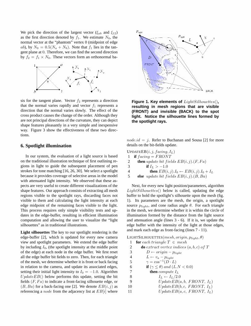
In our system, the evaluation of a light source is basedon the traditional illustration technique of first outlining re-gions in light to guide the subsequent placement of penstrokes for tone matching [16, 26, 30]. We select a spotlightbecause it provides coverage of selective areas in the modelwith attenuated light intensity. We observed that these as-pects are very useful to create different visualizations of theshape features. Our approach consists of extracting all meshregions visible to the spotlight rays, discarding faces notvisible to them and calculating the light intensity at eachedge midpoint of the remaining faces visible to the light.This process requires only simple visibility tests and up-dates in the edge-buffer, resulting in efficient illuminationcomputation and allowing the user to visualize the “lightsilhouettes” as in traditional illustrations.
Light silhouettes The key to our spotlight rendering is theedge-buffer [2], which is updated for every new cameraview and spotlight parameters. We extend the edge bufferby includingI0, (the spotlight intensity at the middle pointof the edge) at each node in the edge buffer. We first resetall the edge buffer bit fields to zero. Then, for each triangleof the mesh, we determine whether it is front or back facingin relation to the camera, and update its associated edges,setting their initial light intensity toI0 = −1.0. AlgorithmUpdateEB() below performs this update, setting the bitfields (F, Fa) to indicate a front-facing silhouette edge, or(B,Ba) for a back-facing one [2]. We denoteEB(i, j) asreferencing anode from the adjacency list atEB[i] where
Figure 1. Key elements of LightSilhouettes(),resulting in mesh regions that are visible(FRONT) and invisible (BACK) to the spotlight. Notice the silhouette lines formed bythe spotlight rays.
node.id = j. Refer to Buchanan and Sousa [2] for moredetails on the bit-fields update.
UPDATEEB(i, j, facing, IL)1 if facing = FRONT2 then update bit fields EB(i, j).(F, Fa)3 if IL > −1.04 then EB(i, j).I0 ← EB(i, j).I0 + IL
5 else update bit fields EB(i, j).(B,Ba)
Next, for every new light position/parameters, algorithmLightSilhouettes() below is called, updating the edgebuffer to hold the spotlight’s silhouette upon the mesh (fig.1). Its parameters are the mesh, the origin, a spotlightsourceplight, and cone radius angleθ. For each trianglein the mesh, we determine whether it is within the circle ofillumination formed by the distance from the light sourceand attenuation angle (lines 3 - 6). If it is, we update theedge buffer with the intensity of the light at those edges,and mark each edge as front-facing (lines 7 - 11).
L IGHTSILHOUETTES(mesh, origin, plight, θ)1 for each triangle T ∈ mesh2 do extract vertex indices (a, b, c) of T3 D ← origin− plight
4 L← va − plight
5 γ = cos−1(D · L)6 if (γ ≤ θ) and (L.N < 0.0)7 then compute IL
8 IL ← IL/2.09 UpdateEB(a, b, FRONT, IL)
10 UpdateEB(b, c, FRONT, IL)11 UpdateEB(a, c, FRONT, IL)
Target tone In our system the spotlight intensity (the targettone) is computed asIL = I0(D · L)/(kc + kld + kqd
2),where I0 is the user-defined light intensity,d is the dis-tance fromPlight to triangle vertexa, and(kc, kl, kq) arethe (user-defined) constant, linear, and quadratic attenua-tion factors, respectively. Notice that the light intensity ofthe edge is equal to the averaged intensities of its two adja-cent triangles. This is achieved by first dividing the originalintensity by two (line 8 inLightSilhouettes()) and thenadding it toI0 in the edge-buffer (line 4 inUpdateEB()).
Value gradation One technique used by illustrators tograde target tone variations is to enlarge the space be-tween strokes, as the tone gets closer to full light inten-sity [18] (figure below).
We reproduce this techniqueby simply adjusting thelengthof the stroke directly at eachmesh edge, thus creating thosespace variations. This pro-cedure works as follows: the
edge-buffer is traversed, and for every edgeab, a singlepen mark is modeled by first determining its stroke baseline endpoints(p0, p1), wherep0 is the midpoint ofab andp1 = p0 + ρφ~d. The proportion of ink to be deposited isgiven byρ = 1.0 − I0, with I0 being the light intensity atthe midpoint of edgeab; φ is a user-defined length value forthe stroke, and~d is the stroke direction equal toe1, e2, f1
or f2 depending on which directional field the user selects(sec. 5).
Value reversal In our system, the effect oftone value rever-sal (or negative film) can be computed by simply assigningρ = I0, which reverses the original light intensity. Thiseffect allows fast visualizations of different contrast tonecombinations, an important illustration composition tech-nique used to create focus of attention at specific shape fea-tures of the subject [10]. Figure 3 illustrates the results ofusing this effect in our system.
7. Stroke qualities
At this stage, we include attributes along the stroke baseline p0p1 to approximate the visual qualities of traditionalink strokes. Our system supports the attributes of weightdistribution and path perturbation.
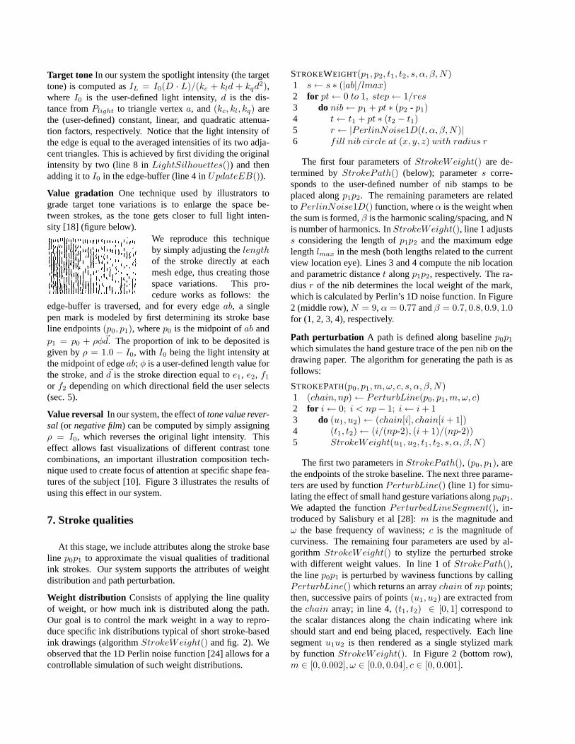
Weight distribution Consists of applying the line qualityof weight, or how much ink is distributed along the path.Our goal is to control the mark weight in a way to repro-duce specific ink distributions typical of short stroke-basedink drawings (algorithmStrokeWeight() and fig. 2). Weobserved that the 1D Perlin noise function [24] allows for acontrollable simulation of such weight distributions.
STROKEWEIGHT(p1, p2, t1, t2, s, α, β,N)1 s← s ∗ (|ab|/lmax)2 for pt← 0 to 1, step← 1/res3 do nib← p1 + pt ∗ (p2 - p1)4 t← t1 + pt ∗ (t2 − t1)5 r ← |PerlinNoise1D(t, α, β,N)|6 fill nib circle at (x, y, z) with radius r
The first four parameters ofStrokeWeight() are de-termined byStrokePath() (below); parameters corre-sponds to the user-defined number of nib stamps to beplaced alongp1p2. The remaining parameters are relatedto PerlinNoise1D() function, whereα is the weight whenthe sum is formed,β is the harmonic scaling/spacing, and Nis number of harmonics. InStrokeWeight(), line 1 adjustss considering the length ofp1p2 and the maximum edgelengthlmax in the mesh (both lengths related to the currentview location eye). Lines 3 and 4 compute the nib locationand parametric distancet alongp1p2, respectively. The ra-dius r of the nib determines the local weight of the mark,which is calculated by Perlin’s 1D noise function. In Figure2 (middle row),N = 9, α = 0.77 andβ = 0.7, 0.8, 0.9, 1.0for (1, 2, 3, 4), respectively.
Path perturbation A path is defined along baselinep0p1
which simulates the hand gesture trace of the pen nib on thedrawing paper. The algorithm for generating the path is asfollows:
STROKEPATH(p0, p1,m, ω, c, s, α, β,N)1 (chain, np)← PerturbLine(p0, p1,m, ω, c)2 for i← 0; i < np− 1; i← i + 13 do (u1, u2)← (chain[i], chain[i + 1])4 (t1, t2)← (i/(np-2), (i + 1)/(np-2))5 StrokeWeight(u1, u2, t1, t2, s, α, β,N)
The first two parameters inStrokePath(), (p0, p1), arethe endpoints of the stroke baseline. The next three parame-ters are used by functionPerturbLine() (line 1) for simu-lating the effect of small hand gesture variations alongp0p1.We adapted the functionPerturbedLineSegment(), in-troduced by Salisbury et al [28]:m is the magnitude andω the base frequency of waviness;c is the magnitude ofcurviness. The remaining four parameters are used by al-gorithm StrokeWeight() to stylize the perturbed strokewith different weight values. In line 1 ofStrokePath(),the linep0p1 is perturbed by waviness functions by callingPerturbLine() which returns an arraychain of np points;then, successive pairs of points(u1, u2) are extracted fromthe chain array; in line 4,(t1, t2) ∈ [0, 1] correspond tothe scalar distances along the chain indicating where inkshould start and end being placed, respectively. Each linesegmentu1u2 is then rendered as a single stylized markby functionStrokeWeight(). In Figure 2 (bottom row),m ∈ [0, 0.002], ω ∈ [0.0, 0.04], c ∈ [0, 0.001].
(1) (2) (3) (4)
Figure 2. Top row: Real samples of ink distri-bution patterns along a straight pen strokewith (1, 2) decreasing and (3, 4) varied pres-sure of the pen nib [11]. Middle row: approx-imations to the real samples by applying al-gorithm StrokeWeight() to a single line seg-ment. Bottom row: suggesting hand gesturevariations by applying algorithm StrokePath()to the weighted lines in middle row.
8. Results and discussion
The table below shows the average times (in seconds) forpre-processing and rendering (without light) all the strokesof the models presented in this paper. Running times weregathered from a 2.65 GHz Pentium IV with OpenGL/ATIRadeon 9700 graphics.
4mesh edges PP L W P W+PInner ear 16,373 < 1 < 1 1 3 10Pelvis/hands 42,231 1 1 7 14 27Skull 49,133 1 1 10 27 45Dental arcade 118,999 2 2 20 42 70Igea artifact 136,484 2 2 25 57 94
Pre-processing (PP) refers to construction of the edge bufferand calculation of stroke directional fields. The remainingcolumns refer to rendering a single straight line (L), addingweight toL, perturbation (P), and lastly adding both weightand perturbation toL. In our current system, models can beinteractively visualized and composed (with spotlight) withjust simple lines (L) and then rendered fairly quickly (butnot interactively) with full stylization (W , P , W + P ) toget a better artistic effect. As expected, rendering times de-crease depending on the spotlight cone angle selected, dueto the discarding of triangles not visible to the light rays.
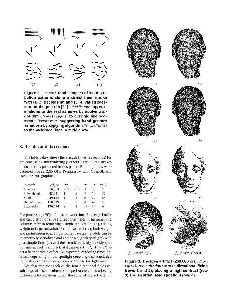
We observed that each of the four directional fields re-sult in good visualizations of shape features, thus allowingdifferent interpretations about the form of the subject. In
e1 e2
f1 f2
f1 f2
f1, switching to−→ f2, reversed value
Figure 3. The Igea artifact (268,686 4s). Fromtop to bottom:the four stroke directional fields(rows 1 and 2); placing a high-contrast (row3) and an attenuated spot light (row 4).
the Igea artifact (fig. 3),f1 andf2 clearly provide betterdepiction of shape features and overall form. Notice howthe two directional fields allow different interpretations ofthe same facial features. Directionf1 seems to depict thevolume of facial features (i.e. lips, nose), whereasf2 seemsto direct the visualization along the length of the face. Thesame figure shows the effect of high-contrast lighting andvalue reversal after an attenuated spotlighting. Notice thematerial wear patterns revealed at the facial regions (fig. 3,bottom-most row).
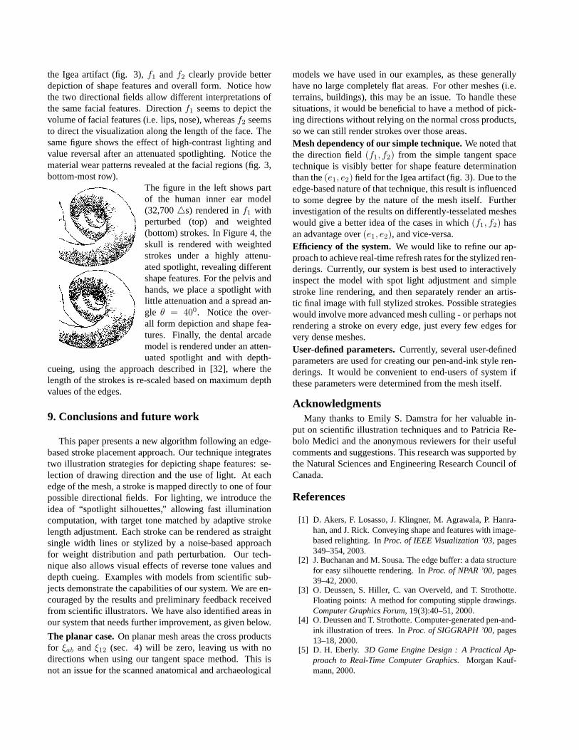
The figure in the left shows partof the human inner ear model(32,7004s) rendered inf1 withperturbed (top) and weighted(bottom) strokes. In Figure 4, theskull is rendered with weightedstrokes under a highly attenu-ated spotlight, revealing differentshape features. For the pelvis andhands, we place a spotlight withlittle attenuation and a spread an-gle θ = 400. Notice the over-all form depiction and shape fea-tures. Finally, the dental arcademodel is rendered under an atten-uated spotlight and with depth-
cueing, using the approach described in [32], where thelength of the strokes is re-scaled based on maximum depthvalues of the edges.
9. Conclusions and future work
This paper presents a new algorithm following an edge-based stroke placement approach. Our technique integratestwo illustration strategies for depicting shape features: se-lection of drawing direction and the use of light. At eachedge of the mesh, a stroke is mapped directly to one of fourpossible directional fields. For lighting, we introduce theidea of “spotlight silhouettes,” allowing fast illuminationcomputation, with target tone matched by adaptive strokelength adjustment. Each stroke can be rendered as straightsingle width lines or stylized by a noise-based approachfor weight distribution and path perturbation. Our tech-nique also allows visual effects of reverse tone values anddepth cueing. Examples with models from scientific sub-jects demonstrate the capabilities of our system. We are en-couraged by the results and preliminary feedback receivedfrom scientific illustrators. We have also identified areas inour system that needs further improvement, as given below.
The planar case.On planar mesh areas the cross productsfor ξab and ξ12 (sec. 4) will be zero, leaving us with nodirections when using our tangent space method. This isnot an issue for the scanned anatomical and archaeological
models we have used in our examples, as these generallyhave no large completely flat areas. For other meshes (i.e.terrains, buildings), this may be an issue. To handle thesesituations, it would be beneficial to have a method of pick-ing directions without relying on the normal cross products,so we can still render strokes over those areas.Mesh dependency of our simple technique.We noted thatthe direction field(f1, f2) from the simple tangent spacetechnique is visibly better for shape feature determinationthan the(e1, e2) field for the Igea artifact (fig. 3). Due to theedge-based nature of that technique, this result is influencedto some degree by the nature of the mesh itself. Furtherinvestigation of the results on differently-tesselated mesheswould give a better idea of the cases in which(f1, f2) hasan advantage over(e1, e2), and vice-versa.Efficiency of the system.We would like to refine our ap-proach to achieve real-time refresh rates for the stylized ren-derings. Currently, our system is best used to interactivelyinspect the model with spot light adjustment and simplestroke line rendering, and then separately render an artis-tic final image with full stylized strokes. Possible strategieswould involve more advanced mesh culling - or perhaps notrendering a stroke on every edge, just every few edges forvery dense meshes.User-defined parameters.Currently, several user-definedparameters are used for creating our pen-and-ink style ren-derings. It would be convenient to end-users of system ifthese parameters were determined from the mesh itself.
AcknowledgmentsMany thanks to Emily S. Damstra for her valuable in-
put on scientific illustration techniques and to Patricia Re-bolo Medici and the anonymous reviewers for their usefulcomments and suggestions. This research was supported bythe Natural Sciences and Engineering Research Council ofCanada.
References
[1] D. Akers, F. Losasso, J. Klingner, M. Agrawala, P. Hanra-han, and J. Rick. Conveying shape and features with image-based relighting. InProc. of IEEE Visualization ’03, pages349–354, 2003.
[2] J. Buchanan and M. Sousa. The edge buffer: a data structurefor easy silhouette rendering. InProc. of NPAR ’00, pages39–42, 2000.
[3] O. Deussen, S. Hiller, C. van Overveld, and T. Strothotte.Floating points: A method for computing stipple drawings.Computer Graphics Forum, 19(3):40–51, 2000.
[4] O. Deussen and T. Strothotte. Computer-generated pen-and-ink illustration of trees. InProc. of SIGGRAPH ’00, pages13–18, 2000.
[5] D. H. Eberly. 3D Game Engine Design : A Practical Ap-proach to Real-Time Computer Graphics. Morgan Kauf-mann, 2000.
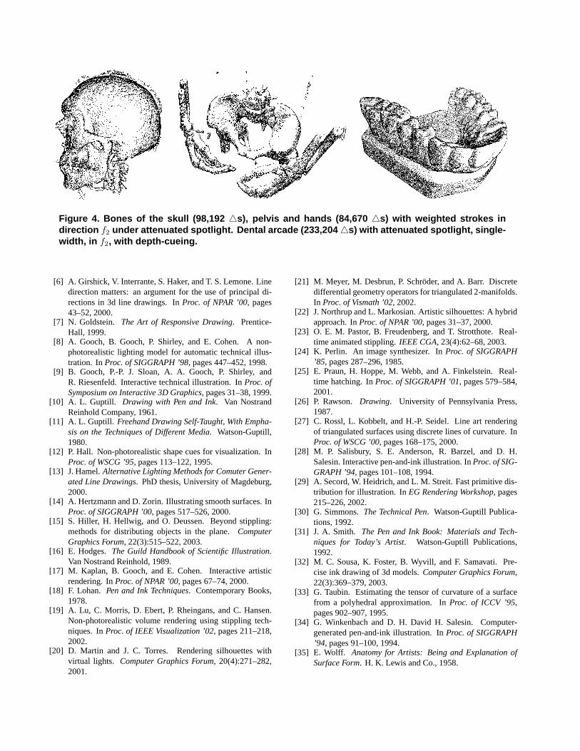
Figure 4. Bones of the skull (98,192 4s), pelvis and hands (84,670 4s) with weighted strokes indirection f2 under attenuated spotlight. Dental arcade (233,204 4s) with attenuated spotlight, single-width, in f2, with depth-cueing.
[6] A. Girshick, V. Interrante, S. Haker, and T. S. Lemone. Linedirection matters: an argument for the use of principal di-rections in 3d line drawings. InProc. of NPAR ’00, pages43–52, 2000.
[7] N. Goldstein. The Art of Responsive Drawing. Prentice-Hall, 1999.
[8] A. Gooch, B. Gooch, P. Shirley, and E. Cohen. A non-photorealistic lighting model for automatic technical illus-tration. InProc. of SIGGRAPH ’98, pages 447–452, 1998.
[9] B. Gooch, P.-P. J. Sloan, A. A. Gooch, P. Shirley, andR. Riesenfeld. Interactive technical illustration. InProc. ofSymposium on Interactive 3D Graphics, pages 31–38, 1999.
[10] A. L. Guptill. Drawing with Pen and Ink. Van NostrandReinhold Company, 1961.
[11] A. L. Guptill. Freehand Drawing Self-Taught, With Empha-sis on the Techniques of Different Media. Watson-Guptill,1980.
[12] P. Hall. Non-photorealistic shape cues for visualization. InProc. of WSCG ’95, pages 113–122, 1995.
[13] J. Hamel.Alternative Lighting Methods for Comuter Gener-ated Line Drawings. PhD thesis, University of Magdeburg,2000.
[14] A. Hertzmann and D. Zorin. Illustrating smooth surfaces. InProc. of SIGGRAPH ’00, pages 517–526, 2000.
[15] S. Hiller, H. Hellwig, and O. Deussen. Beyond stippling:methods for distributing objects in the plane.ComputerGraphics Forum, 22(3):515–522, 2003.
[16] E. Hodges.The Guild Handbook of Scientific Illustration.Van Nostrand Reinhold, 1989.
[17] M. Kaplan, B. Gooch, and E. Cohen. Interactive artisticrendering. InProc. of NPAR ’00, pages 67–74, 2000.
[18] F. Lohan. Pen and Ink Techniques. Contemporary Books,1978.
[19] A. Lu, C. Morris, D. Ebert, P. Rheingans, and C. Hansen.Non-photorealistic volume rendering using stippling tech-niques. InProc. of IEEE Visualization ’02, pages 211–218,2002.
[20] D. Martin and J. C. Torres. Rendering silhouettes withvirtual lights. Computer Graphics Forum, 20(4):271–282,2001.
[21] M. Meyer, M. Desbrun, P. Schroder, and A. Barr. Discretedifferential geometry operators for triangulated 2-manifolds.In Proc. of Vismath ’02, 2002.
[22] J. Northrup and L. Markosian. Artistic silhouettes: A hybridapproach. InProc. of NPAR ’00, pages 31–37, 2000.
[23] O. E. M. Pastor, B. Freudenberg, and T. Strotthote. Real-time animated stippling.IEEE CGA, 23(4):62–68, 2003.
[24] K. Perlin. An image synthesizer. InProc. of SIGGRAPH’85, pages 287–296, 1985.
[25] E. Praun, H. Hoppe, M. Webb, and A. Finkelstein. Real-time hatching. InProc. of SIGGRAPH ’01, pages 579–584,2001.
[26] P. Rawson. Drawing. University of Pennsylvania Press,1987.
[27] C. Rossl, L. Kobbelt, and H.-P. Seidel. Line art renderingof triangulated surfaces using discrete lines of curvature. InProc. of WSCG ’00, pages 168–175, 2000.
[28] M. P. Salisbury, S. E. Anderson, R. Barzel, and D. H.Salesin. Interactive pen-and-ink illustration. InProc. of SIG-GRAPH ’94, pages 101–108, 1994.
[29] A. Secord, W. Heidrich, and L. M. Streit. Fast primitive dis-tribution for illustration. InEG Rendering Workshop, pages215–226, 2002.
[30] G. Simmons.The Technical Pen. Watson-Guptill Publica-tions, 1992.
[31] J. A. Smith. The Pen and Ink Book: Materials and Tech-niques for Today’s Artist. Watson-Guptill Publications,1992.
[32] M. C. Sousa, K. Foster, B. Wyvill, and F. Samavati. Pre-cise ink drawing of 3d models.Computer Graphics Forum,22(3):369–379, 2003.
[33] G. Taubin. Estimating the tensor of curvature of a surfacefrom a polyhedral approximation. InProc. of ICCV ’95,pages 902–907, 1995.
[34] G. Winkenbach and D. H. David H. Salesin. Computer-generated pen-and-ink illustration. InProc. of SIGGRAPH’94, pages 91–100, 1994.
[35] E. Wolff. Anatomy for Artists: Being and Explanation ofSurface Form. H. K. Lewis and Co., 1958.