Rate-controlled optical burst switching for both congestion avoidance and service differentiation
Upload
independentCategory
view
0download
0
JOURNAL OF LIGHTWAVE TECHNOLOGY, VOL. 21, NO. 11, NOVEMBER 2003 2723
Demonstration of All-Optical Packet SwitchingRouters With Optical Label Swapping
and 2R Regeneration for ScalableOptical Label Switching
Network ApplicationsMin Yong Jeon, Member, OSA, Zhong Pan, Jing Cao, Student Member, IEEE, Student Member, OSA, Yash Bansal,
Julie Taylor, Zubin Wang, Venkatesh Akella, Katsunari Okamoto, Senior Member, IEEE, Shin Kamei,James Pan, Member, IEEE, and S. J. Ben Yoo, Member, OSA
Abstract—This paper investigates comprehensive operation andexperimentation of an all-optical packet switching router with op-tical label swapping and reamplification and reshaping (2R) regen-eration, capable of multihop operation and Internet protocol (IP)-client interoperability. In particular, the experiment demonstratessuccessful packet switching and transport up to 11 hops with 10 9
bit-error rate and error-free up to four hops. Furthermore, thispaper demonstrates the optical label switching (OLS) core routerand edge routers working together to support IP-client-to-IP-clientpacket transport and switching across the optical label switchingnetwork. The edge router generates an optical label based on theIP header content of the packet and generates an optical label en-coded packet, which subsequently ingresses into the OLS network.The optical label switching router (OLSR) forwards the packetwith all-optical label swapping at each hop with 2R regeneration.The 2R regeneration leads to an experimentally measured negativepenalty and a successful experimental demonstration of multihopcascaded OLSR operation with the edge routers interfacing withIP clients. The successful IP-client-to-IP-client packet forwardingvia the edge routers and the cascaded multihop OLSR with all-op-tical label swapping indicate the viability of OLS in the scalableand transparent IP-over-optical Internet.
Index Terms—All-optical networks (AONs), optical Internet, op-tical label swapping, optical label switching (OLS), optical packetswitching, subcarrier multiplexing (SCM), wavelength conversion.
Manuscript received December 16, 2002; revised July 25, 2003. Thiswork was supported in part by the Defense Advanced Research ProjectsAgency (DARPA) and the Air Force Research Laboratory under AgreementF30602-00-2-0543,and the National Science Foundation under Grant AdvancedNetwork Infrastructure ANI-9986665, and Sprint.
M. Y. Jeon was with the Department of Electrical and Computer Engineering,University of California, Davis, CA 95616 USA. He is now with the Chung NamNational University, Daejeon, Korea.
Z. Pan, J. Cao, Y. Bansal, J. Taylor, Z. Wang, V. Akella, and S. J. B. Yooare with the Department of Electrical and Computer Engineering, University ofCalifornia, Davis, CA 95616 USA (e-mail: [email protected]).
K. Okamoto is with the Okamoto Laboratory, Ltd., Ibaraki 310-0035, Japan.S. Kamei is with the NTT Photonics Laboratories, Kanagawa 243-0198,
Japan.J. Pan is with the SPRINT Advanced Technology Laboratory, Burlingame,
CA 94010 USA.Digital Object Identifier 10.1109/JLT.2003.819563
I. INTRODUCTION
OPTICAL LABEL SWITCHING (OLS) technology hasmade key progress in providing the low-latency and
transparent switching desired for the next-generation Internet[1], [2]. It is also an attractive technology to accommodateInternet protocol (IP)-over-optical on a wavelength-divi-sion-multiplexing (WDM) platform using a shim layer thatemploys optical labels. Label swapping can be an impor-tant technology to provide scalability in multiprotocol labelswitching (MPLS) [3] and OLS networks [1], [2]. All-opticallabel swapping may avoid the complexity of optical-to-elec-trical (O/E) and electrical-to-optical (E/O) conversions in OLSnetworks, especially when it is coupled with rapid opticalswitching to provide optical-label-based packet switching.All-optical regeneration and label swapping may offer mul-tihop packet transport and switching in scalable OLS networkswithout resorting to repeated O/E and E/O conversions. Aprogrammable and pipelined optical router controller witha forwarding table can allow asynchronous switching inan all-optical packet switching fabric without resorting tobuffers for store-and-forward switching. Such OLS corerouters working with OLS edge routers for interfacing with IPclients provide ultimate possibilities for IP-client-to-IP-clientpacket transport across the all-optical OLS network. Thispaper investigates and demonstrates comprehensive operationand experimental studies of OLS routers (OLSRs) with theaforementioned desired characteristics.
Optical label swapping capability is critically dependenton the encoding method for attaching the optical label ontothe packet. Optical subcarrier multiplexing (SCM) [4]–[10] isan attractive label-encoding scheme from this perspective. Itaccommodates both the label and the baseband data payloadon the same optical wavelength by treating the payload as abaseband signal while including the label as the subcarrier[7]–[9]. Compared with bit-serial time-domain label-encodingtechniques [11], SCM techniques facilitate label swapping inthat frequency-dependent separation of the label, and the datapayload is feasible. Optical label swapping techniques reportedso far involve relatively complex single side-band transmitters
0733-8724/03$17.00 © 2003 IEEE

2724 JOURNAL OF LIGHTWAVE TECHNOLOGY, VOL. 21, NO. 11, NOVEMBER 2003
Fig. 1. Basic architecture of OLS networks.
[10], bulky-fiber-based nonlinear optical schemes [11], [20],interferometric wavelength converter schemes with large powerpenalty [7], overmodulating schemes with intermodulationpenalty [12], or multiwavelength label schemes with relativelylow spectral efficiency [19]. For cascaded operations, [19]reported three-hop label swapping based on multiwavelengthlabel switching. [20] reported two-hop optical label swappingusing relatively bulky nonlinear fiber wavelength converter.In addition to the limitations mentioned here previously, thedemonstrated OLS systems lacked time-to-live (TTL) or opticalregeneration considerations. Recent system demonstrations ofSCM label swapping have been limited to single-hop operationswith label swapping [15] and a two-hop operation without labelor data regeneration [16].
Optical regeneration is important for cascadability ofOLSRs and scalability of OLS networks without resortingto optical–electrical–optical (O/E/O) regeneration. Opticalre-amplification and reshaping (2R) regeneration can providesignificant improvement in cascadability of optical systemsby confining the signal degradations in the amplitude domainsuch as signal-to-noise ratio reductions and signal distortiondue to dispersion or nonlinearities. Optical reamplification,reshaping, and retiming (3R) regeneration can offer additionalimprovement in the time domain to overcome timing jittersby retiming. While 3R regeneration using wavelength con-verters has demonstrated 1 000 000-km transmission and 2500cascaded wavelength conversion [23], it also requires clockrecovery and retiming, which are extremely difficult in opticalpacket switching networks since the packets arrive at burstrates. 2R regeneration is far simpler and offers regenerationcapabilities limited by the time-domain degradations, such astiming jitters. This paper will investigate OLS core routerswith all-optical label swapping that include 2R regeneration.Using the regenerative optical label swapping, this paper willdemonstrate an OLSR [13] with a cascaded multihop operationup to 11 hops with 1E-9 bit-error rate (BER) and error-free upto four hops.
Fig. 1 illustrates the basic architecture of an OLS network.The IP packets enter the core router at the ingress edge routerand propagate through the core network. The router controllerin each core router uses the contents of the extracted labels
to perform the forwarding decision and forward the packetstoward their egress edge router. Each optical core router per-forms routing and forwarding operations together with wave-length conversion and label swapping. The all-optical packetswitching router in the core performs routing and forwardingoperations through tunable wavelength conversion [14] and all-optical label swapping [15]. In the control plane, the router ex-tracts the optical label from the packet and makes the forwardingdecision based on the content of the label and the forwardingtable. Edge routers provide an interface between legacy net-works and the OLS network. They take advantage of queuingin the electrical domain to enhance OLS network performance.Optical labels are produced at the edge router, based on the con-tent of the legacy packets. The optical labels and data payloadsare then encoded and sent to the OLS network as an opticalpacket. This paper will demonstrate an OLS edge router capableof generating an optical label based on the IP header contentof the packet. Then, the edge router encodes an optical labelswitching packet, which subsequently ingresses into the OLSnetwork with OLS core routers. The 2R regeneration in the OLScore routers leads to a successful experimental demonstration ofmultihop cascaded OLSR operation with the edge routers inter-facing to IP clients.
The organization of this paper is as follows. Section I pro-vides the introduction. Section II discusses the setup and per-formance of an all-optical label rewriting module that also pro-vides 2R regeneration. This module is the key subsystem in theoptical label swapping scheme. Section III demonstrates mul-tihop operation of the OLS system with optical label swapping.Specifically, Section III-B introduces an edge router interfacingwith the OLS core router with a packet over the synchronousoptical network (PoS). Section IV summarizes the paper.
II. ALL-OPTICAL LABEL REWRITING MODULE
AND 2R REGENERATION
This section proposes and demonstrates a new scheme of anall-optical label rewriting module in the OLS network.
A. Experimental Setup of the Label- Rewriting Module
Fig. 2 illustrates the experimental setup of the label rewritingmodule. The two-arm structure realizes wavelength conversion

JEON et al.: DEMONSTRATION OF ALL-OPTICAL PACKET SWITCHING ROUTERS 2725
Fig. 2. All-optical label swapping module: DFB-LD: distributed-feedback laser diode; EDFA: erbium-doped fiber amplifier; OBPF: optical bandpass filter;PC: polarization controller; MZI WC: Mach–Zehnder interferometer wavelength converter; FBG: fiber Bragg grating; Mod: modulator; PBS: polarization beamcombiner; LO: local oscillator; Att.: attenuator; and ISO.: isolator.
and 2R regeneration of the payload in one arm and the mod-ulation of the new label in the other arm, and then combinesthe two together without incurring interference. Details are de-scribed hereafter.
The distributed-feedback laser diode (DFB-LD) providescontinuous-wave (CW) light to both arms through a 1 2fiber coupler. The first two polarization controllers (PC1 andPC2) match the polarizations of the CW lights to the desiredpolarizations of the Mach–Zehnder interferometer wavelengthconverter (MZI WC; Alcatel 1901-ICM) and the LiNbOmodulator, respectively. 50% of the CW light enters the semi-conductor optical amplifier (SOA)-based MZI WC and carriesthe modulation from the old data payload through cross-phasemodulation (XPM). The counterpropagating geometry elim-inates the need for a spectrum filter [21]. This wavelengthconversion also provides 2R regeneration [13]. The other 50%of the CW light is modulated by the subcarrier signal containingthe new label generated by the router controller. To reject theresidue baseband optical carrier after the modulation, the setupincludes a fiber Bragg grating (FBG) with the reflection peakcentered at the wavelength of the DFB-LD, allowing only thedouble sideband SCM label component to pass. The isolator(ISO) prevents the reflected signal from entering the DFB-LD.The polarization controllers (PC3 and PC4) are adjusted suchthat the payload from the upper arm and the label from thelower arm have orthogonal polarizations. Then, the polarizationbeam combiner (PBC) can combine the two optical signalswithout undesired coherent interference. The PCs can beeliminated if polarization maintaining fibers and couplers areutilized in this module [22].
To make the operation of the label-rewriting module clear,Fig. 3 shows typical spectra taken in an experiment at variouspoints in the setup. The remainder of the experiment will beexplained in Section II-B. Fig. 3(a) shows the spectrum of theincoming payload at point (i) in Fig. 2. The carrier center wave-length is 1550.76 nm. Fig. 3(b) shows the spectrum of the wave-length converted and 2R regenerated payload at (ii). The carriercenter wavelength is changed to 1555.73 nm. Fig. 3(c) shows
the spectrum of the new optical label at (iii), with the basebandcarrier component already removed. Fig. 3(d) shows the spec-trum of the final output, the regenerated OLS packet.
B. BER Performance of the Optical Label Swapping
This section describes the BER performance and the systemexperiment of the all-optical label swapping module with 2Rregeneration. Fig. 4 shows the experimental setup. It consistsof five modules. The transmitter module generates the OLSpackets. The fiber-transmission-line module introduces signaldegradation to the OLS packets. The first label extractor (LE1)module separates the label and the payload. The label rewritingmodule (LR) regenerates the payload and attaches a new labelto it. The second label extractor separates the label and thepayload again for final measurements.
The parallel BER tester (ParBERT) synchronously generatesthe electrical label (155 Mb/s) and data payload (2.488 Gb/s)signals. Although there is theoretically no problem for the SCMscheme to accommodate payload data rate at 10 Gb/s, the datarate is limited by the commercial 2.5-Gb/s SOA device we areusing for the cross-gain modulation (XGM) wavelength conver-sion. Higher data rate experiments are in progress. The SCMtransmitter creates the optical packets with the payload as thebaseband signal and the label as the 14-GHz double-sidebandsubcarrier components. In the time domain, the label and thepayload are overlapping. Very strict timing or synchronizationat the bit level is not required between the label and the pay-load. Timing in the context of the multihop OLS network is dis-cussed in Section III-A. The packet duration is 619.4 ns (pay-load 1536 b; label 96 b), with a 206.5-ns guard time betweentwo packets. The data payload contains a pseudorandombit sequence (PRBS). Again, the PRBS length is limited by thecommercial SOA device for XGM wavelength conversion. TheOLS packet may go through a transmission line module com-posed of two erbium-doped fiber amplifiers (EDFAs), an attenu-ator, and a section of 75-km single-mode fiber (SMF). Typically,the double-sideband subcarrier-modulated signal suffers from

2726 JOURNAL OF LIGHTWAVE TECHNOLOGY, VOL. 21, NO. 11, NOVEMBER 2003
Fig. 3. Typical spectra taken in an optical label swapping module: (a) input payload (1550.76 nm); (b) regenerated payload (1555.73 nm); (c) new label(DSB_SCM) without baseband; and (d) regenerated DSB-SCM (0.1 nm/div).
Fig. 4. Experimental setup for optical label swapping module with 2R regeneration: Par BERT: parallel bit-error-rate tester; PPG: programmable pattern generator;LO: local oscillator; DFB-LD: distributed-feedback laser diode; EDFA: erbium-doped fiber amplifier; SMF: single-mode fiber; Mod: modulator; LE: label extractor;FBG: fiber Bragg grating; BPF: bandpass filter; OC: optical circulator; and LR: label rewriting module.
the well-known radio frequency (RF) fading effect in transmis-sion. However, in this scheme, a narrow-band filter (the FBG)removes the payload and the optical carrier before the subcar-rier label is received, thus suppressing RF fading [9]. Moreover,at 2.5 Gb/s, the dispersion and nonlinear effects are negligible.Thus, the major degradation imposed on the optical signal bythe transmission, the attenuation, and the EDFAs is the decreasein optical signal-to-noise ratio (OSNR). After the transmission,LE1 achieves all-optical extraction of the label by utilizing therelatively sharp filtering characteristics of FBG1 [12]. The FBGhas a full-width at half-maximum (FWHM) bandwidth of about
10 GHz, a maximum reflectivity of 99.9%, and a reflectioncenter at 1550.76 nm—the same as the SCM transmitter centerwavelength. The label passes through FBG1 to the label detectorfor BER performance measurements. At the same time, the re-flected data payload goes to the label rewriting module afterbeing amplified by an EDFA. The details of the label rewritingmodule as well as the spectra taken at various places within thelabel- rewriting module are discussed in Section II-A. In thisexperiment, the new label comes from the ParBERT, insteadof the switch controller for BER testing purposes. The regen-erated OLS packet then reaches LE2, which includes the FBG2
JEON et al.: DEMONSTRATION OF ALL-OPTICAL PACKET SWITCHING ROUTERS 2727
Fig. 5. BER test results for label swapping without transmission-line module.(Insets: Eye diagrams of label and payload before and after label swapping.)
with the peak reflection wavelength matching the optical car-rier wavelength of the regenerated packet (1555.73 nm). The ex-tracted label and data payload subsequently undergo BER mea-surements respectively.
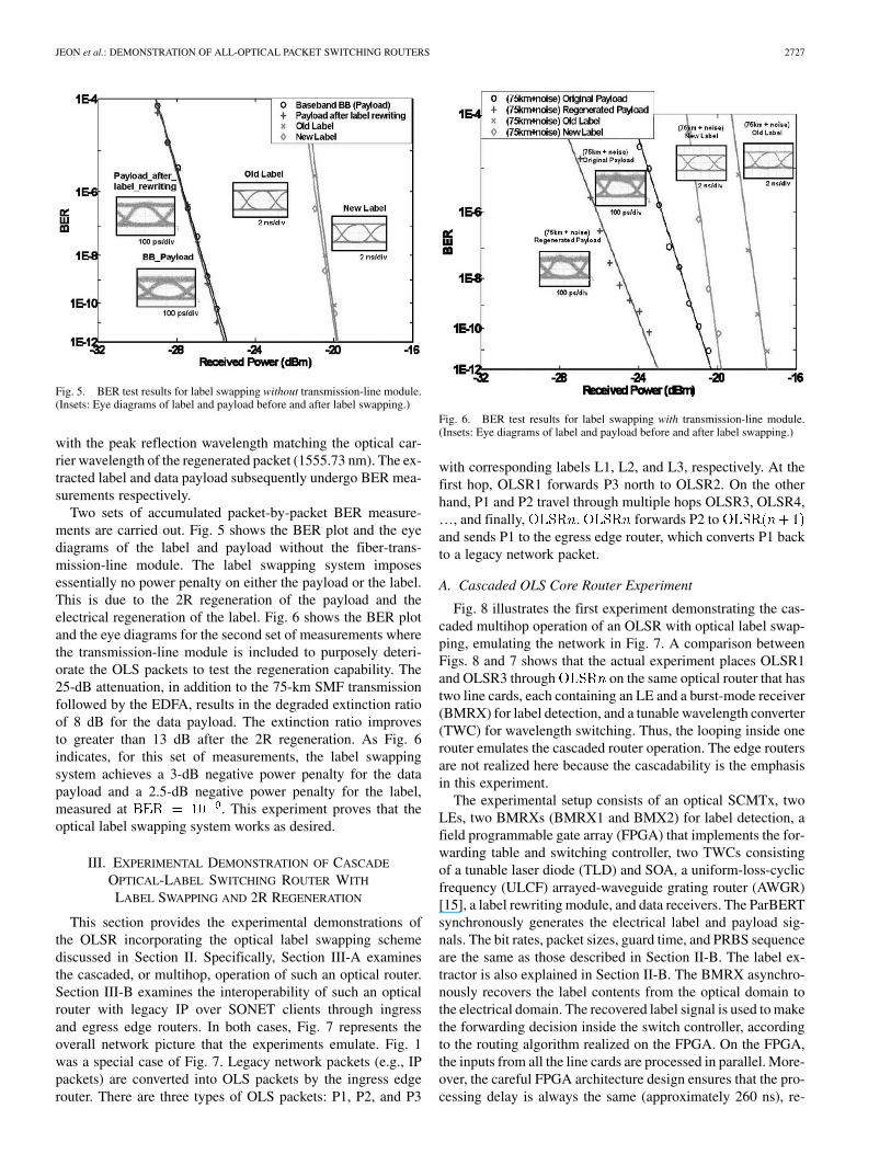
Two sets of accumulated packet-by-packet BER measure-ments are carried out. Fig. 5 shows the BER plot and the eyediagrams of the label and payload without the fiber-trans-mission-line module. The label swapping system imposesessentially no power penalty on either the payload or the label.This is due to the 2R regeneration of the payload and theelectrical regeneration of the label. Fig. 6 shows the BER plotand the eye diagrams for the second set of measurements wherethe transmission-line module is included to purposely deteri-orate the OLS packets to test the regeneration capability. The25-dB attenuation, in addition to the 75-km SMF transmissionfollowed by the EDFA, results in the degraded extinction ratioof 8 dB for the data payload. The extinction ratio improvesto greater than 13 dB after the 2R regeneration. As Fig. 6indicates, for this set of measurements, the label swappingsystem achieves a 3-dB negative power penalty for the datapayload and a 2.5-dB negative power penalty for the label,measured at . This experiment proves that theoptical label swapping system works as desired.
III. EXPERIMENTAL DEMONSTRATION OF CASCADE
OPTICAL-LABEL SWITCHING ROUTER WITH
LABEL SWAPPING AND 2R REGENERATION
This section provides the experimental demonstrations ofthe OLSR incorporating the optical label swapping schemediscussed in Section II. Specifically, Section III-A examinesthe cascaded, or multihop, operation of such an optical router.Section III-B examines the interoperability of such an opticalrouter with legacy IP over SONET clients through ingressand egress edge routers. In both cases, Fig. 7 represents theoverall network picture that the experiments emulate. Fig. 1was a special case of Fig. 7. Legacy network packets (e.g., IPpackets) are converted into OLS packets by the ingress edgerouter. There are three types of OLS packets: P1, P2, and P3
Fig. 6. BER test results for label swapping with transmission-line module.(Insets: Eye diagrams of label and payload before and after label swapping.)
with corresponding labels L1, L2, and L3, respectively. At thefirst hop, OLSR1 forwards P3 north to OLSR2. On the otherhand, P1 and P2 travel through multiple hops OLSR3, OLSR4,…, and finally, . forwards P2 toand sends P1 to the egress edge router, which converts P1 backto a legacy network packet.
A. Cascaded OLS Core Router Experiment
Fig. 8 illustrates the first experiment demonstrating the cas-caded multihop operation of an OLSR with optical label swap-ping, emulating the network in Fig. 7. A comparison betweenFigs. 8 and 7 shows that the actual experiment places OLSR1and OLSR3 through on the same optical router that hastwo line cards, each containing an LE and a burst-mode receiver(BMRX) for label detection, and a tunable wavelength converter(TWC) for wavelength switching. Thus, the looping inside onerouter emulates the cascaded router operation. The edge routersare not realized here because the cascadability is the emphasisin this experiment.
The experimental setup consists of an optical SCMTx, twoLEs, two BMRXs (BMRX1 and BMX2) for label detection, afield programmable gate array (FPGA) that implements the for-warding table and switching controller, two TWCs consistingof a tunable laser diode (TLD) and SOA, a uniform-loss-cyclicfrequency (ULCF) arrayed-waveguide grating router (AWGR)[15], a label rewriting module, and data receivers. The ParBERTsynchronously generates the electrical label and payload sig-nals. The bit rates, packet sizes, guard time, and PRBS sequenceare the same as those described in Section II-B. The label ex-tractor is also explained in Section II-B. The BMRX asynchro-nously recovers the label contents from the optical domain tothe electrical domain. The recovered label signal is used to makethe forwarding decision inside the switch controller, accordingto the routing algorithm realized on the FPGA. On the FPGA,the inputs from all the line cards are processed in parallel. More-over, the careful FPGA architecture design ensures that the pro-cessing delay is always the same (approximately 260 ns), re-

2728 JOURNAL OF LIGHTWAVE TECHNOLOGY, VOL. 21, NO. 11, NOVEMBER 2003
Fig. 7. Schematic diagram of emulated network. OLSR: Optical label switching router.
Fig. 8. Experimental setup for cascaded OLS core router experiment: Par BERT: parallel bit-error-rate tester; LO: local oscillator; EDFA: erbium-doped fiberamplifier; Mod: modulator; FBG: fiber Bragg grating; OC: optical circulator; SOA: semiconductor optical amplifier; TLD: tunable laser diode; TWC: tunablewavelength converter; BMRx: burst-mode receiver; AWGR: arrayed-waveguide grating router; ATT: attenuator; BPF: bandpass filter; and FDL: fiber delay line.
gardless of packet contention and arrival rates. This processingdelay is matched by the right amount of fiber delay (FDL1 andFDL2) such that the payload arrives at the TWC right after thetunable laser switches. The FPGA design also ensures that thewriting of the new label happens at the right time. As a re-sult, the time-domain misalignment between the payload andthe label that belong to the same packet will not accumulatefrom hop to hop. Based on the forwarding decision, the switchcontroller sends a control signal to the TLD to switch to the des-ignated wavelength [15]. The TLD generates a probe light forthe SOA, and XGM modulates the payload onto this designatedwavelength. Payloads with different labels are converted ontodifferent wavelengths corresponding to different desired outputports of the AWGR.
In the experiment, the ParBERT generates repeated patternsof packet 1 (P1), packet 2 (P2), and packet 3 (P3) with differentlabels (L1, L2, L3). The data rates, packet lengths, guard time,and bit pattern are the same as in Section II-B. The label con-
tains destination information as well as a TTL field that decideshow many loops the packet should travel. L1 and L2 have thesame TTL values. The TTL field of L3 is not used since P3 doesnot enter the multihop loop. According to L1, L2, and L3, theforwarding table and controller tunes the wavelength of TLD1to (1544.3 nm), (1544.3 nm), and (1555.6 nm), re-spectively. Thus, P1 and P2 are converted to , while P3 isconverted to . After the AWGR, P3 is forwarded to OLSR2while P1 and P2 go to the label rewriting module. Section II-Bdiscussed the details of the label rewriting module. The switchcontroller generates new labels L1’ and L2’ with the TTL fieldsdecreased by 1. The new label mixes with the 14-GHz sub-carrier and drives the modulator in the label rewriting module.At the same time, payload P1 and P2 are regenerated to thefixed wavelength (1555.7 nm) in the SOA-based MZI WC byXPM. The converted payloads and the new labels form packets.The packets travel to line card 2, where, by similar process,the switch controller sends control signals to TLD2 according

JEON et al.: DEMONSTRATION OF ALL-OPTICAL PACKET SWITCHING ROUTERS 2729
Fig. 9. Timing diagram of the cascaded OLS core router experiment for the three-hop case: SCM TX: subcarrier-multiplexing transmitter; LC: line card (it isa set of BMRX, LE, and TWC combining together that can provide one input to the AWGR); FPGA: field programmable gate array (the forwarding table andcontroller); LR: label rewriting module; P: payload; L: label. (a) Step-by-step snapshots of the OLSR operation. For simplicity, some P3s injected by the transmitterto avoid collision have been ignored. (b) Illustrative packet sequences observed at various locations in the setup. Location numbers such as correspond to thosein Fig. 8. The number in parentheses on top of a label represents the TTL value in that label. t : Packet length; 619.4 ns. t : Guard time; 206.5 ns. T : Total lengthof P1 and P2 together; 1.652 �s. t : Processing delay; approximately 260 ns. t : Loop delay; 1.652 �s matching T .
to the new labels. Based on the contents of L1’ and L2’, theforwarding table and controller instruct the packets to be con-verted to (1548 nm) if the TTL fields are greater than 0,or (1552.2 nm) and (1563.6 nm) otherwise. As a result,when the TTL fields are greater than 0, P1 and P2 continue tothe label rewriting module to form a loop. At the same time,the ParBERT only sends in P3 to avoid packet collisions in theloop. When the TTL fields decrease to 0, P1 goes to the finaloutput for BER measurements and P2 goes to .At the same time, the ParBERT resumes sending P1 and P2to start a new round. Thus, by using different TTL values, theexperiment demonstrates two-, three-, four-, six-, and 11-hopoperations.
Fig. 9 shows the timing diagram for a three-hop case. Fig. 9(a)shows the step-by-step snapshots of the router operation, andFig. 9(b) shows the packet sequences at various locations in thesetup. These points are also marked in Fig. 8. is the packetlength (619.4 ns), and is the guard time (206.5 ns). From point
(right after the transmitter) to point (right after ATT5 be-fore the AWGR), there is a processing delay , which is approx-imately 260 ns. Same processing delay occurs from point(right after the loop delay) to point (right after ATT6 beforethe AWGR). The loop delay occurs between point and .To be simple, it is ensured that 1.652 sso that the loop delay equals an integral number of the totallength of packets that travel in the loop. All other delays are

2730 JOURNAL OF LIGHTWAVE TECHNOLOGY, VOL. 21, NO. 11, NOVEMBER 2003
Fig. 10. Experimental results of cascaded OLSR core router experiment.(a) Waveforms of packets for the six-hop case. Top: Tapping of EDFA2.Bottom: Final output (P1). (b) Packet-by-packet BER test result. B2B:Back-to-back. (Insets: Eye diagrams of payload signals.)
small and thus ignored in Fig. 9(b) for simplicity. The numberin the parentheses on top of a label represents the TTL valuecontained in that label. From the packet sequence at point ,
, and , we can see how the TTL decreases at each hop.Fig. 10 shows the experimental results. Fig. 10(a) shows
the packet waveforms for the six-hop case. The top trace isfrom the tapping of EDFA2. The logic inversions are due tothe XGM wavelength converter. The bottom is the final outputof P1. Packet-by-packet BER measurements take place on thefinal output of P1 for each hop count. Fig. 10(b) shows theBER curves. The insets show the payload eye diagrams ofthe final output (P1), all with clear openings. The six curvesare for back-to-back, after two, three, four, six, and 11 hops,respectively. Comparing with back-to-back, all other BERcurves show apparent negative power penalties. This is due toreduction in the average power with reduction in the duty cyclefor the higher hop numbers. After the normalization of thereceived power considering the above effects, the penalties fortwo, three, and four hops are 0.2, 0.1, and 0 dB, respectively,which are negligibly small. The power penalties are measuredat . Error floors appear at forsix hops and for 11 hops, possibly due to theaccumulated timing jitter and residue pattern dependence ofXGM-based wavelength converters. The XGM-based SOA
wavelength converters SOA1, SOA2 (Alcatel 1901-SOA)exhibit timing jitters and pattern dependence at 2.5 Gb/sunless very high power levels are used. Replacing themwith XPM-based wavelength converters (10-Gb/s Alcatel1901-ICM) and introducing 3R regeneration could eliminatethe timing jitter and improve the system performance, thuspossibly removing the error floor.
B. Edge Router for a Multihop OLS Network
The second experiment demonstrates IP client-to-IP-clientpacket communication via edge routers and cascaded opticallabel switching core routers. As in MPLS networks, OLSnetworks require edge routers or edge devices to performoptical label generation with label distribution protocol. Edgerouters in OLS networks also function as important interfacesfor IP, MPLS [3], asynchronous transfer mode (ATM) [17], orany legacy format clients or client networks. The main functionof an OLS edge router is to seamlessly interface networksthat use different protocols by generating or extracting opticallabels to be used in the OLS core network.
The working principle of the edge routers is as follows. Theingress edge router receives synchronous PoS frames from theclient network emulated by the IXIA performance analyzer. Itthen assembles the contents of the frames into point-to-point-protocol (PPP)-encapsulated IP packets. If an IP packet spansmultiple SONET frames, the IP packet is reassembled beforethe ingress edge router further processes the packet. Althoughnot realized in this experiment, the IP packets can be variablesize, as demonstrated in a recent experiment [19], [24]. Theingress edge router, operating as a layer 3 device, uses the con-tents of the IP header to generate a label containing a preamble,an egress edge router destination address, a priority, a packetduration, an optical TTL, and the source address of the ingressedge router. The OC-3 label and the OC-48 PPP-encapsulatedIP packets are then forwarded to the SCM transmitter for trans-mission to the asynchronous OLS network. Upon receipt ofthe PPP-encapsulated IP packets, the egress edge router bytealigns the asynchronously received packets, converts them toPoS frames, and sends them to the emulated client network.
Fig. 11 shows the experimental setup for two-hopIP-client-to-IP-client communication using edge routersand OLS core routers. This emulates the network in Fig. 7.The IXIA OC-48c POS Load Module emulates the PoS clientnetwork. It generates and sends three different 1500-B IPpackets, P1, P2, and P3, to the ingress edge router. Each kindof packet has a different destination IP address. The edgerouter reads the IP headers, generates labels L1, L2, and L3at 155 Mb/s, and places them on the three payloads, P1, P2,and P3 at 2.488 Gb/s using SCM, thus creating three kindsof optical label encoded packets. The OLS core router isessentially the same as that described in Section III-A. BMRx1recovers the contents of L1, L2, and L3 and sends them tothe FPGA-based router controller, while the payloads P1, P2,and P3 are amplified and delayed using an EDFA to match the
260 ns processing time through the router controller. Usingthe recovered labels, the router controller decides where toforward the packets and sends the appropriate control signalsto the first TLD1. TLD1 with the SOA2 converts P1 and P2 to

JEON et al.: DEMONSTRATION OF ALL-OPTICAL PACKET SWITCHING ROUTERS 2731
Fig. 11. Experimental setup for two-hop IP-client-to-IP-client communication using edge routers and OLS core router: SCM Tx: subcarrier multiplexingtransmitter; EDFA: erbium-doped fiber amplifier; Mod: modulator; FBG: fiber Bragg grating; OC: optical circulator; SOA: semiconductor optical amplifier; MZIWC: Mach–Zehnder-interferometer-based wavelength converter; TLD: tunable laser diode; BMRx: burst-mode receiver; AWGR: arrayed-waveguide gratingrouter; LPF: low-pass filter; and PoS: packet over SONET.
1552 nm and P3 to 1546 nm as dictated by the router controllerbased on the contents of L1, L2, and L3. SOA1 and SOA3 areused instead of the EDFA to amplify the packets, thus avoidingthe gain transient of EDFA. The two wavelengths then assumethe switching paths determined by the well-known wavelengthrouting characteristics of the AWGR. This results in droppingP3 at first hop drop port and forwarding P1 and P2 to EDFA1,where optical gain clamping is used to reduce the gain transient[18]. The router controller generates two new labels, L1’ andL2’, updating the contents if necessary. In the label rewritingmodule, P1 and P2 are subcarrier multiplexed with their newlabels, L1’ and L2’.
The optical packets with new labels now enter the secondhop through label extractor 2, where the OLS core router per-forms forwarding similar to the first hop with an SOA-basedMZI WC used in place of the SOA. The router forwards P2to a drop port (1542 nm) and forwards P1 to the receiver andegress edge router (1546 nm). The egress edge router receivesP1 and converts the received OLS packet to SONET frames andsends them back to the IXIA OC-48c PoS load module for per-formance analysis.
Fig. 12 shows the measured packet error rate (PER). The edgerouter and the IXIA performance analyzer function as layer 3devices that have no layer 1 or 2 testing access. Hence, the BERcannot be obtained. The crossing in the PER curves is due to thereduction in average optical power after dropping packets. Theinset of Fig. 12 shows the packet patterns, and the eye diagramsshow back-to-back, after one-hop, and after two-hop routing, re-spectively. All eye diagrams show clear openings. These resultsalso indicate the successful operation of the OLS edge and theOLS core routers for IP client to IP client packet transport overthe OLS network with cascaded stages of optical routers.
Fig. 12. Measured packet error rate (PER) for two-hop IP-client-to-IP-clientcommunication using edge routers and OLS core router. The insets show packetpattern as well as the eye diagrams of the payload signals.
IV. SUMMARY
We proposed and demonstrated an all-optical label swappingsystem with 2R regeneration capability. The all-optical labelswapping achieved near-zero power penalty for a high-qualityinput signal and negative power penalty for a deteriorated inputsignal for both labels and data payloads. Using the label swap-ping scheme, we demonstrated cascaded operation of an all-op-tical packet routing system. The experiment emulated opticalpacket switching through two, three, four, six, and 11 hops in

2732 JOURNAL OF LIGHTWAVE TECHNOLOGY, VOL. 21, NO. 11, NOVEMBER 2003
the network. Error-free operation was achieved for the two-,three-, and four-hop cases with negligible power penalty. Errorfloors appeared at in the 6-loop case and at in the11-hop case. The possible causes are the accumulated time jit-ters and the residue pattern dependence of the XGM wavelengthconverter. We also demonstrated the routing of optical packetsfrom IP client- to IP client over a two-hop OLS core routers in-corporating edge routers. The interoperation between the corerouters and the IP clients emulated by the IXIA performanceanalyzer through the edge routers were successful, resulting ina low packet loss rate.
REFERENCES
[1] S. J. B. Yoo, G. K. Chang, and Bellcore, U. S. A, “High-throughput,low-latency next generation internet using optical tag switching,” U. S.Patent 6 111 673, Aug. 29, 2000.
[2] B. Meagher, G. K. Chang, G. Ellinas, Y. M. Lin, W. Xin, T. F. Chen,X. Yang, A. Chowdhury, J. Young, S. J. Yoo, C. Lee, M. Z. Iqbal, T.Robe, H. Dai, Y. J. Chen, and W. I. Way, “Design and implementationof ultra-low latency optical label switching for packet-switched WDMnetworks,” J. Lightwave Technol., vol. 18, pp. 1978–1987, Dec. 2000.
[3] A. Viswanathan, N. Feldman, Z. Wang, and R. Callon, “Evolutionof multiprotocol label switching,” IEEE Commun. Mag., vol. 36, pp.165–173, May 1998.
[4] R. Olshansky and V. A. Lanzisera, “60-channel FM video subcarriermultiplexed optical communication system,” Electron. Lett., vol. 23, pp.1196–1198, 1987.
[5] I. M. White, M. S. Rogge, K. Shrikhande, Y. Fukashiro, D.Wonglumsom, F.-T. An, and L. G. Kazovsky, “Experimentaldemonstration of a novel media access protocol for HORNET: Apacket-over-WDM multiple-access MAN ring,” IEEE Photon. Technol.Lett., vol. 12, pp. 1264–1266, Sept. 2000.
[6] G. Rossi, O. Jerphagnon, B.-E. Olsson, and D. J. Blumenthal, “OpticalSCM data extraction using a fiber-loop mirror for WDM network sys-tems,” IEEE Photon. Technol. Lett., vol. 12, pp. 897–899, July 2000.
[7] D. J. Blumenthal, A. Carena, L. Rau, V. Curri, and S. Humphries, “All-optical label swapping with wavelength conversion for WDM-IP net-works with subcarrier multiplexed addressing,” IEEE Photon. Technol.Lett., vol. 11, pp. 1497–1499, Nov. 1999.
[8] A. Carena, M. D. Vaughn, R. Gaudino, M. Shell, and D. J. Blumenthal,“OPERA: An optical packet experimental routing architecture with labelswapping capability,” J. Lightwave Technol., vol. 16, pp. 2135–2145,Dec. 1998.
[9] H. J. Lee, V. Hernandez, V. K. Tsui, and S. J. B. Yoo, “Simple, polar-ization-independent, and dispersion-insensitive SCM signal extractiontechnique for optical switching systems applications,” Electron. Lett.,vol. 37, pp. 1240–1241, Sept. 2001.
[10] Y. M. Lin, W. I. Way, and G. K. Chang, “A novel optical label swappingtechnique using erasable optical single-sideband subcarrier label,” IEEEPhoton. Technol. Lett., vol. 12, pp. 1088–1090, Aug. 2000.
[11] B. E. Olsson, P. Ohlen, L. Rau, G. Rossi, O. Jerphagnon, R. Doshi,D. S. Humphries, D. J. Blumenthal, V. Kaman, and J. E. Bowers,“Wavelength routing of 40 Gbit/s packets with 2.5 Gbit/s headererasure/rewriting using all-fiber wavelength converter,” Electron. Lett.,vol. 36, pp. 345–347, Feb. 2000.
[12] H. J. Lee, S. J. B. Yoo, V. K. Tsui, and S. K. Fong, “A simple all-op-tical label detection and swapping technique incorporating a fiber Bragggrating filter,” IEEE Photon. Technol. Lett., vol. 13, pp. 635–637, June2001.
[13] D. Wolfson, A. Kloch, T. Fjelde, C. Janz, B. Dagens, and M. Renaud,“40-Gb/s all-optical wavelength conversion, regeneration, and demul-tiplexing in an SOA-based all-active Mach–Zehnder interferometer,”IEEE Photon. Technol. Lett., vol. 12, pp. 332–334, Mar. 2000.
[14] S. J. B. Yoo, “Wavelength conversion technologies foe WDM networkapplications,” J Lightwave Technol., vol. 14, pp. 942–954, June 1996.
[15] S. J. B. Yoo, H. J. Lee, Z. Pan, J. Cao, Y. Zhang, K. Okamoto, and S.Kamei, “Rapidly switching all-optical packet routing system with op-tical-label swapping incorporating tunable wavelength conversion anda uniform-loss cyclic frequency AWGR,” IEEE Photon. Technol. Lett.,vol. 14, pp. 1211–1213, Aug. 2002.
[16] J. Cao, Z. Pan, M. Y. Jeon, Y. Bansal, J. Taylor, V. Akella, S. Kamei,K. Okamoto, and S. J. B. Yoo, “Cascaded operation of an optical packetrouting system with optical-label switching and 2-R regeneration,” Tech.Dig., ECOC2002, 2002.
[17] F. Masetti, J. Benoit, F. Brillouet, J. M. Gabriagues, A. Jourdan, M. Re-naud, D. Bottle, G. Eilenberger, K. Wunstel, M. Schilling, D. Chiaroni,P. Gavignet, J. B. Jacob, G. Bendelli, P. Cinato, P. Gambini, M. Puleo,T. Martinson, and P. Vogel, “High speed, high capacity ATM opticalswitches for future telecommunication transport networks,” IEEE J. Se-lect. Areas Commun., vol. 14, pp. 979–998, June 1996.
[18] M. Zirngibl, “Gain control in erbium-doped fiber amplifiers by an all-optical feedback loop,” Electron. Lett., vol. 27, pp. 560–561, 1991.
[19] N. Wada, H. Harai, and W. Chujo, “Multi-hop, 40 Gbit/s variable lengthphotonic packet routing based on multi-wavelength label switching,waveband routing and label swapping,” in Optical Fiber Communica-tions Conf. (OFC 2002) Postconf. Tech. Dig., vol. 1, (IEEE Cat. No.02CH37339), pp. 216–217.
[20] L. Rau, S. Rangarajan, D. J. Blumenthal, H.-F. Chou, Y.-J. Chiu, andJ. E. Bowers, “Two-hop all-optical label swapping with variable length80 Gb/s packets and 10 Gb/s labels using nonlinear fiber wavelengthconverters, unicast/multicast output and a single EAM for 80- to 10-Gb/spacket demultiplexing,” in Optical Fiber Communications Conf. (OFC2002) Postconf. Tech. Dig. Postdeadline Papers, vol. 2, pp. FD2-1–3.
[21] T. Durhuus, C. Joergensen, B. Mikkelsen, R. J. S. Pedersen, andK. E. Stubkjaer, “All optical wavelength conversion by SOA’s in aMach–Zehnder configuration,” IEEE Photon. Technol. Lett., vol. 6, pp.53–55, Jan. 1994.
[22] E. L. Goldstein and L. Eskildsen, “Scaling limitations in transparent op-tical networks due to low-level crosstalk,” IEEE Photon. Technol. Lett.,vol. 7, pp. 93–94, Jan. 1995.
[23] J. Leuthold, G. Raybon, Y. Su, R. Essiambre, S. Cabot, J. Jaques, andM. Kauer, “40 Gbit/s transmission and cascaded all-optical wavelengthconversion over 1 000 000 km,” Electron. Lett., vol. 38, pp. 890–892,Aug. 2002.
[24] Z. Pan, H. Yang, Z. Zhu, J. Cao, V. Akella, S. Butt, and S. J. Ben Yoo, “Experimental demonstration of variable-size packet contention resolu-tion and switching in an optical-label switching router,” in Optical FiberCommunications Conf. 2004 (OFC 2004), Los Angeles, CA, Feb. 2004,submitted for publication.
Min Yong Jeon received the B.S. degree from Han Yang University, Seoul,Korea, in 1988 and the M.S. and Ph.D. degrees from Korea Advanced Instituteof Science and Technology (KAIST), Daejeon, Korea, in 1990 and 1994, re-spectively, all in physics.
Prior to joining Chung Nam University, he worked in the area of opticalrouters, as a Research Scientist at the University of California, Davis. From1994 to 2001, he worked in the area of the optical network subsystem at the Elec-tronics and Telecommunications Research Institute (ETRI), Daejeon, Korea. Hehas been with the Chung Nam National University, Daejeon, Korea, as an Assis-tant Professor of Physics since May 2003. His current research interests includecharacterization and application of optical switching technologies, amplifiers,lasers and optical nonlinear effects.
Prof. Jeon is a Member of the Optical Society of America (OSA).
Zhong Pan, photograph and biography not available at the time of publication.
Jing Cao (S’03) received the B.S. and M.S. degrees from the Department ofElectronics Engineering, Tsinghua University, Beijing, China, in 1997 and2000, respectively, and is working toward the Ph.D. degree at the Electrical andComputer Engineering Department, University of California, Davis.
His research focuses on optical integrated devices and system integration fornext-generation optical networks.
Mr. Cao is a Student Member of the Optical Society of America (OSA).
Yash Bansal, photograph and biography not available at the time of publication.
Julie Taylor, photograph and biography not available at the time of publication.

JEON et al.: DEMONSTRATION OF ALL-OPTICAL PACKET SWITCHING ROUTERS 2733
Zubin Wang, photograph and biography not available at the time of publication.
Venkatesh Akella, photograph and biography not available at the time ofpublication.
Katsunari Okamoto (M’85–SM’98) was born in Hi-roshima, Japan, on October 19, 1949. He receivedthe B.S., M.S., and Ph.D. degrees in electronics en-gineering from Tokyo University, Tokyo, Japan, in1972, 1974, and 1977, respectively.
He joined Ibaraki Electrical CommunicationLaboratory, Nippon Telegraph and Telephone Cor-poration, Ibaraki, Japan, in 1977 and was engagedin the research on transmission characteristicsof multimode, dispersion-flattened single-mode,single-polarization (PANDA) fibers, and fiber-optic
components. He proposed for the first time the dispersion-flattened fiber(DFF) and succeeded in fabrication of DFF that had chromatic dispersionless than ±1 ps/km/nm over a wide spectral range. Since 1990, he has beenworking on the analysis and the synthesis of guided-wave devices and thecomputer-aided-design and fabrication of silica-based planar lightwave circuits(PLCs) at Ibaraki R&D Center, NTT Photonics Laboratories. He has developeda 256 × 256 star coupler, various kinds of arrayed-waveguide gratings (AWGs)ranging from 8 ch–50 nm spacing AWGs to 128 ch–25 GHz AWGs, flat spectralresponse AWGs, and integrated-optic reconfigurable add/drop multiplexers.In 2003, he started Okamoto Laboratory, Ltd., Ibaraki, Japan, a research anddevelopment consulting company that deals with the custom design of opticalfibers and functional PLCs. He has published more than 210 papers in technicaljournals and international conferences. He has authored and coauthored eightbooks, including Fundamentals of Optical Waveguides.
Dr. Okamoto is a Member of the Institute of Electronics, Information andCommunication Engineers (IEICE) of Japan.
Shin Kamei, photograph and biography not available at the time of publication.
James Pan (M’95), photograph and biography not available at the time ofpublication.
S. J. Ben Yoo received the B.S. degree in electricalengineering with distinction, the M.S. degree inelectrical engineering, and the Ph.D. degree inelectrical engineering with a minor degree in physicsfrom Stanford University, Stanford, CA, in 1984,1986, and 1991, respectively. His Ph.D. dissertationwas on linear and nonlinear optical spectroscopy ofquantum-well intersubband transitions.
Prior to joining Bellcore in 1991, he conductedresearch on nonlinear optical processes in quantumwells, a four-wave-mixing study of relaxation
mechanisms in dye molecules, and ultrafast diffusion driven photodetectors.During this period, he also conducted research on lifetime measurements ofintersubband transitions and on nonlinear optical storage mechanisms at BellLaboratories and IBM Research Laboratories, respectively. He was then aSenior Scientist at Bellcore, leading technical efforts in optical networkingresearch and systems integration. His research activities at Bellcore includedoptical-label switching for the Next Generation Internet, power transients inreconfigurable optical networks, wavelength interchanging cross-connects,wavelength converters, vertical-cavity lasers, and high-speed modulators. Healso participated in the Advanced Technology Demonstration Network andMultiwavelength Optical Networking (ATD/MONET) systems integration, theOC-192 synchronous optical network (SONET) ring studies, and a numberof standardization activities. He joined the University of California, Davis(UC Davis), as Associate Professor of electrical and computer engineering inMarch 1999. He is currently the Branch Director of the Center for InformationTechnology Research in the Interest of Society (CITRIS). His current researchinvolves advanced switching techniques and optical communications systemsfor the Next Generation Internet. In particular, he is conducting research onarchitectures, systems integration, and network experiments of all-optical labelswitching routers.
Prof. Yoo is a Senior Member of IEEE Lasers & Electro-Optics Society(LEOS), and a Member of the Optical Society of America (OSA) and TauBeta Pi. He received the Bellcore CEO Award in 1998 and DARPA Award forSustained Excellence in 1997 for his work at Bellcore.
Copyright © 2022 FDOKUMEN