All-optical techniques enabling packet switching with label processing and label rewriting
Upload
independentCategory
view
2download
0
Computer Networks 51 (2007) 1882–1907
www.elsevier.com/locate/comnet
A survey of IP and multiprotocol label switchingfast reroute schemes
Alex Raj a, Oliver C. Ibe b,*
a Cisco Systems, Inc., 1414 Massachusetts Avenue, Boxborough, MA 01719, United Statesb Department of Electrical and Computer Engineering, University of Massachusetts, Lowell, MA 01854, United States
Received 5 December 2005; received in revised form 6 June 2006; accepted 21 September 2006Available online 19 October 2006
Responsible Editor: M. Smirnow
Abstract
One of the desirable features of any network is its ability to keep services running despite a link or node failure. Thisability is usually referred to as network resilience and has become a key demand from service providers. Resilient networksrecover from a failure by repairing themselves automatically by diverting traffic from the failed part of the network toanother portion of the network. This traffic diversion process should be fast enough to ensure that the interruption of servicedue to a link or node failure is either unnoticeable or as small as possible. The new path taken by a diverted traffic can becomputed at the time a failure occurs through a procedure called rerouting. Alternatively the path can be computed before afailure occurs through a procedure called fast reroute. Much attention is currently being paid to fast reroute because serviceproviders who are used to the 50-ms failure recovery time associated with SONET networks are demanding the same featurefrom IP and MPLS networks. While this requirement can easily be met in SONET because it operates at the physical layer, itis not easily met in IP and MPLS networks that operate above the physical layer. However, over the last few years, severalschemes have been proposed for accomplishing 50-ms fast reroutes for IP and MPLS networks. The purpose of this paper isto provide a survey of the IP fast reroute and MPLS fast reroute schemes that have been proposed.� 2006 Elsevier B.V. All rights reserved.
Keywords: MPLS networks; IP fast reroute; Protection switching; Micro-loop prevention; Loop-free alternate; U-turn alternate
1. Introduction
One of the desirable features of any network is itsability to keep services running despite a link ornode failure. This ability of a network to keep ser-vices running despite a failure is usually referredto as network resilience and has always been a key
1389-1286/$ - see front matter � 2006 Elsevier B.V. All rights reserved
doi:10.1016/j.comnet.2006.09.010
* Corresponding author. Tel.: +1 978 934 3118.E-mail address: [email protected] (O.C. Ibe).
attribute for a network infrastructure. Service pro-viders commonly advertise availability numbers forbusiness services. If they fail to meet the advertisedavailability numbers, the providers are likely to paypenalties to their customers. Resilient networksrecover from a failure by repairing themselves auto-matically by diverting traffic from the failed part ofthe network to another part of the network. Thistraffic diversion process should be fast enough toensure that the interruption of service due to a link
.
A. Raj, O.C. Ibe / Computer Networks 51 (2007) 1882–1907 1883
or node failure is either unnoticeable or as small aspossible. The new path taken by the diverted trafficcan be either computed at the time failures occur orbefore failures. The first method of traffic diversionin which a new path is established for traffic restora-tion after the occurrence of a fault is called restora-
tion or reroute. The other method of traffic diversionin which a backup path is pre-established for trafficrestoration before the occurrence of a fault is calledprotection switching or fast reroute.
Fast reroute mechanisms provide decreased inter-ruption of service compared to non-pre-plannedschemes. However, they may introduce additionalcomplexity and consume valuable resources, suchas extra connectivity and computational cycles tocompute backup paths.
A major challenge in an IP network [36] is for thenodes to converge on a common view of the newtopology after a node or link failure has occurred.During this process, which is referred to as a routingtransition, packet delivery between certain source–destination pairs may be disrupted. This is due tothe time it takes for the topology change to be prop-agated around the network, plus the time it takeseach node to determine and then update theforwarding information base (FIB) for the affecteddestinations. FIB maintains the forwarding informa-tion derived from the IP routing table. Thus, whenrouting or topology changes occur in the network,the routing table is updated, and those changes arereflected in the FIB. During a routing transition,packets may be lost because of the continuingattempts to use the failed component, and also as aresult of the formation of forwarding loops calledmicro-loops. Micro-loops arise from the inconsistentFIBs that occur as a result of the difference in timetaken by nodes to execute the routing transition pro-cess. Thus, while a node closer to the failed compo-nent can quickly revise its routes to work around thefailure, a node that is farther away will take a muchlonger time to react to the failure, and this leads toinconsistencies that give rise to forwarding loops.
Although service failures caused by routing tran-sitions are largely hidden by higher-level protocolsthat retransmit the lost data, new Internet servicesare emerging that are very sensitive to the packetdisruption that occurs during a transition. For therouting transition to be transparent to such users,it should be as short as possible. The best-case sce-nario is for the routing transitions to be completedin zero time with no packet loss. Transient micro-loops are common in current IP networks. How-
ever, because there is no strict time imposed onthe normal reroute, transient micro-loops are notan issue for the normal reroutes.
Service providers are used to the fact that theSynchronous Optical Network (SONET) standardsspecify that the service interruption time shouldnot exceed 50 ms, which is short enough for the out-age to be unnoticeable by customers who participatein a live conversation where voice is carried over aSONET network. This has motivated Layer 3designers of fast reroute schemes to aim at solvingthe reroute traffic loss issues, including micro-loops,in no more than 50 ms.
Rerouting in SONET occurs at the physicallayer, which is fast but requires extra dedicatedfiber. On the other hand, current IP rerouting doesnot satisfy the 50-ms failure recovery requirement.Over the last few years, several schemes have beenproposed for accomplishing the 50-ms fast reroutesfor IP and Multiprotocol Label Switching (MPLS)networks [31]. These have come to be known asIP fast reroute (FRR) and MPLS fast reroute
schemes, respectively. MPLS networks use two inte-rior gateway protocols (IGPs), namely Label Distri-
bution Protocol (LDP) and Resource Reservation
Protocol (RSVP) Traffic Engineering (TE) protocol.Since the fast reroute procedures are defined in theLayer 3, each of these MPLS protocols requires itsown fast reroute scheme. The purpose of this paperis to provide a survey of the IP fast reroute andMPLS fast reroute schemes that have been pro-posed. The paper is organized as follows. Section2 provides an overview of MPLS. Section 3discusses different types of micro-loops. Section 4discusses MPLS Traffic Engineering fast rerouteschemes. Section 5 discusses IP fast reroute schemes.Section 6 discusses MPLS LDP fast reroute schemesthat use IP fast reroute. Finally, concluding remarksare made in Section 7.
2. MPLS overview
MPLS capabilities enhance the services providedby IP networks by providing strict quality of service(QoS) and traffic engineering. Traffic engineeringgives network operators a great deal of flexibilityto divert and route traffic around link failures andcongestion points in a network. In an MPLS net-work, incoming traffic is assigned a ‘‘label’’ by alabel edge router (LER). Traffic is forwarded alonga label switched path (LSP) where each label switch
router (LSR) makes forwarding decisions based

1884 A. Raj, O.C. Ibe / Computer Networks 51 (2007) 1882–1907
solely on the contents of the label. At each hop, theLSR removes the existing label from a packet andapplies a new label, which tells the next hop howto forward the packet.
Label switched paths can be established eitherautomatically or by network operators for a varietyof purposes, such as to guarantee a certain level ofperformance, to route around network congestion,or to create IP tunnels for virtual private networks.An LSP can be established that crosses multipleLayer 2 transports, such as ATM, Frame Relay orEthernet. Thus, one of the true promises of MPLSis the ability to create end-to-end circuits, with spe-cific performance characteristics, across any type oftransport medium, eliminating the need for overlaynetworks or Layer 2-only control mechanisms.
MPLS label switching methods allow routers tomake forwarding decisions based on the contentsof a simple label, rather than by performing a com-plex route lookup based on destination IP address.However, this initial justification for technologiessuch as MPLS is no longer perceived as the mainbenefit because Layer 3 switches (or ASIC-basedrouters) are able to perform route lookups at suffi-cient speeds to support most interface types. MPLSis normally built with a scalable IP control planeand technology-independent data plane. It is usedwith IP packet routers, ATM switches and opticalswitches in the data plane. This helps in keepingthe benefits of all these data plane technologieswhile building a large scalable network.
The above observation notwithstanding, MPLSbrings many other benefits to IP-based networks,and these include:
• IP Virtual Private Networks (VPNs) – UsingMPLS, service providers can create Layer 3 IPVPNs in their networks, with private route andforwarding tables.
• Layer 2 Transport – New standards being definedby the IETF’s PWE3 and PPVPN workinggroups allow service providers to carry Layer 2services, including Ethernet, Frame Relay andATM, over an IP/MPLS core.
• MPLS Traffic Engineering (TE) – This employsthe constraint-based routing in which the pathfor a traffic flow is the shortest path that meetsthe resource requirements or constraints of thetraffic flow.
• MPLS TE Fast ReRoute (FRR) – This mecha-nism routes traffic around network outages usinga pre-determined path and provides telecommu-
nications networks the same 50-ms protectionas SONET. Thus, it is a mechanism that is usedto protect MPLS TE LSPs from link and nodefailures by locally repairing the LSPs at the pointof failure, allowing data to continue to flow onthem while their headend routers attempt toestablish new end-to-end LSPs to replace them.A backup path that bypasses only a single linkof the primary path provides link protection,and a backup path that bypasses a single nodeof the primary path provides node protection.
Therefore, the flexibility of MPLS enables modernnetworks to achieve next-generation Layer 2 andLayer 3 VPNs, better QoS, and scalable controlplane for optical networks.
MPLS uses two signaling protocols to establishand maintain the label bindings between MPLSnodes in the IGP and hence set up LSPs within anMPLS network. These are
• Resource Reservation Protocol (RSVP) TrafficEngineering (TE), which is used to establishMPLS LSPs when there are traffic engineeringrequirements. Thus, it is primarily used to pro-vide QoS and load balancing across the networkcore. It uses MPLS tunnels that forward the traf-fic along the explicit path. The tunnel explicitpath can be provisioned, or it can be automati-cally computed using the constraint-based short-est path first (CSPF) calculations. In RSVP-TEfast reroute, when the failure occurs on thePacket over SONET (POS) network, the trafficis routed to the backup tunnel within 50 ms.The RSVP-TE fast reroute time or data loss iscomparable to the SONET automatic protectionswitching (APS). Service providers prefer theRSVP-TE fast reroute over SONET APS protec-tion because RSVP-TE does not require addi-tional expensive fiber for protection. RSVP-TEfast reroute has been used in MPLS service pro-vider networks for many years.
• MPLS Label Distribution Protocol (LDP), whichis used for setting up LSPs based on IP routes.LDP provides automatic MPLS tunnels accord-ing to IP routes with MPLS label encapsulation.Unlike RSVP-TE, LDP does not have the capa-bility of source routing and directed forwarding.The LDP LSP always follows the IP route.Because LDP is simple and easy to configureand manage, most service providers use LDPfor their network core.
Routed path
Backup path
D
R3
R1 R2
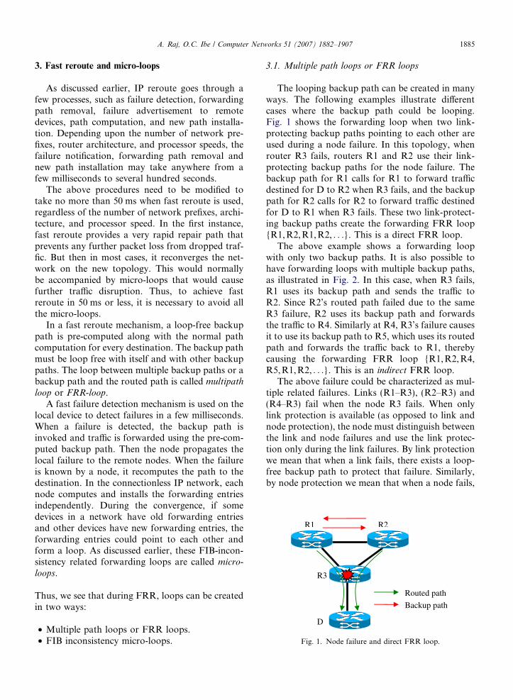
Fig. 1. Node failure and direct FRR loop.
A. Raj, O.C. Ibe / Computer Networks 51 (2007) 1882–1907 1885
3. Fast reroute and micro-loops
As discussed earlier, IP reroute goes through afew processes, such as failure detection, forwardingpath removal, failure advertisement to remotedevices, path computation, and new path installa-tion. Depending upon the number of network pre-fixes, router architecture, and processor speeds, thefailure notification, forwarding path removal andnew path installation may take anywhere from afew milliseconds to several hundred seconds.
The above procedures need to be modified totake no more than 50 ms when fast reroute is used,regardless of the number of network prefixes, archi-tecture, and processor speed. In the first instance,fast reroute provides a very rapid repair path thatprevents any further packet loss from dropped traf-fic. But then in most cases, it reconverges the net-work on the new topology. This would normallybe accompanied by micro-loops that would causefurther traffic disruption. Thus, to achieve fastreroute in 50 ms or less, it is necessary to avoid allthe micro-loops.
In a fast reroute mechanism, a loop-free backuppath is pre-computed along with the normal pathcomputation for every destination. The backup pathmust be loop free with itself and with other backuppaths. The loop between multiple backup paths or abackup path and the routed path is called multipath
loop or FRR-loop.A fast failure detection mechanism is used on the
local device to detect failures in a few milliseconds.When a failure is detected, the backup path isinvoked and traffic is forwarded using the pre-com-puted backup path. Then the node propagates thelocal failure to the remote nodes. When the failureis known by a node, it recomputes the path to thedestination. In the connectionless IP network, eachnode computes and installs the forwarding entriesindependently. During the convergence, if somedevices in a network have old forwarding entriesand other devices have new forwarding entries, theforwarding entries could point to each other andform a loop. As discussed earlier, these FIB-incon-sistency related forwarding loops are called micro-
loops.
Thus, we see that during FRR, loops can be createdin two ways:
• Multiple path loops or FRR loops.• FIB inconsistency micro-loops.
3.1. Multiple path loops or FRR loops
The looping backup path can be created in manyways. The following examples illustrate differentcases where the backup path could be looping.Fig. 1 shows the forwarding loop when two link-protecting backup paths pointing to each other areused during a node failure. In this topology, whenrouter R3 fails, routers R1 and R2 use their link-protecting backup paths for the node failure. Thebackup path for R1 calls for R1 to forward trafficdestined for D to R2 when R3 fails, and the backuppath for R2 calls for R2 to forward traffic destinedfor D to R1 when R3 fails. These two link-protect-ing backup paths create the forwarding FRR loop{R1, R2,R1, R2, . . .}. This is a direct FRR loop.
The above example shows a forwarding loopwith only two backup paths. It is also possible tohave forwarding loops with multiple backup paths,as illustrated in Fig. 2. In this case, when R3 fails,R1 uses its backup path and sends the traffic toR2. Since R2’s routed path failed due to the sameR3 failure, R2 uses its backup path and forwardsthe traffic to R4. Similarly at R4, R3’s failure causesit to use its backup path to R5, which uses its routedpath and forwards the traffic back to R1, therebycausing the forwarding FRR loop {R1, R2, R4,R5,R1, R2, . . .}. This is an indirect FRR loop.
The above failure could be characterized as mul-tiple related failures. Links (R1–R3), (R2–R3) and(R4–R3) fail when the node R3 fails. When onlylink protection is available (as opposed to link andnode protection), the node must distinguish betweenthe link and node failures and use the link protec-tion only during the link failures. By link protectionwe mean that when a link fails, there exists a loop-free backup path to protect that failure. Similarly,by node protection we mean that when a node fails,

R5
R1
D
R3
R2
R4
Routed path
Backup path
Fig. 2. Node failure and indirect FRR loop.
Figure 3
Backup path Switch L
D
R1 R2
Routed path
Fig. 3. Link (R1–L) failure.
Figure 4
Backup path
Switch L
Routed path
D
R1 R2
Fig. 4. Switch L failure.
1886 A. Raj, O.C. Ibe / Computer Networks 51 (2007) 1882–1907
there exists a loop-free backup path to protect thatfailure.
The links sharing the same risk are defined as aShared Risk Link Group (SRLG). When the backuppath is computed, this SRLG information must beincluded in the backup path computation to avoidloops. The SRLG is commonly associated used withoptical link bundles. Multiple optical fibers are bun-dled in a single physical transport during the opticalcable installation. When the optical cable is dam-aged, it affects all the fibers traveling in that bundle.For example, in Fig. 2 the links (R1–R3), (R2–R3),and (R4–R3) could be fibers on the same opticaltransport bundle. When there is a cut in this bundle,it creates multiple related failures, as in the case ofthe R3 failure. The router R3 failure can also beconsidered as an SRLG’s failure to compute aloop-free backup path. This type of fiber bundleor single-point-of-failure information must also beconsidered during the loop-free backup path com-putation to avoid loops.
When there is a Layer 2 switch between the Layer3 devices, only the local device directly attached tothe failure can detect the link failure. Until theremote device detects the failure, the traffic isdropped. Therefore, when there is a Layer 2 switchbetween the Layer 3 devices, other fast failure-detec-tion procedures, such as Bidirectional ForwardingDetection (BFD) [19] or protocol-specific fast hello,must be used. BFD is a protocol used to detectfaults in the bidirectional path between two for-warding engines, including physical interfaces, logi-cal sub-interfaces, data link(s), and, if possible, theforwarding engines themselves, with potentially verylow latency. BFD operates independently of media,data protocols, and routing protocols.
In Non-Broadcast Multiple Access (NBMA) net-works, such as local area networks (LANs), there
are two possible types of failures: failure of a linkbetween a Layer 3 router and the Layer 2 switch,and failure of the Layer 2 switch.
In the LAN environment shown in Fig. 3, whenthe link connecting R1 to the switch L fails, R1 usesthe backup path to R2. This is similar to the routercase if the link has a single neighbor. If the link isconnecting multiple neighbors using Virtual LAN(VLAN) interfaces, then the collection of VLANson a link can be considered as a shared risk linkgroup, and SRLG-based backup path computationshould be used to compute the backup path.
In Fig. 4, when the switch L fails, R1 sends thetraffic to R2 and R2 sends it back to R1, therebycreating a loop. This is similar to the router failureshown in Fig. 2. However, the node failure mecha-nism used in the routers cannot be used on theswitch L.
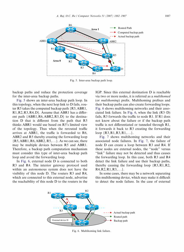
Fast reroute mechanisms normally use link-statetopology to compute the backup path. In the link-state topology, routers in one area do not haveknowledge of the topologies of other areas. Thislimited knowledge may limit the use of inter-area
Area 1
R5
R4
D
ABR2
R6
Area 0
Computed backup path
Actual backup path
ABR1
R1
R2
R3
Routed Path
Fig. 5. Inter-area backup path loop.
A. Raj, O.C. Ibe / Computer Networks 51 (2007) 1882–1907 1887
backup paths and reduce the protection coveragefor the inter-area backup paths.
Fig. 5 shows an inter-area backup path loop. Inthis topology, when the next hop link to D fails, rou-ter R5 takes the computed backup path {R5, ABR1,R1, R2,R3, R4,D}. Assume that ABR1 has a differ-ent path {ABR1,R6, ABR2,R5,D} to the destina-tion D that is different from the path that R5thinks ABR1 would use based on R5’s limited viewof the topology. Thus when the rerouted trafficarrives at ABR1, the traffic is forwarded to R6,ABR2 and R5 thereby creating the forwarding loop{R5, ABR1,R6,ABR2, R5, . . .}. As we can see, theremay be multiple devices between R5 and ABR1.Therefore, a backup path computation mechanismmust consider this type of inter-area backup pathloop and avoid the forwarding loop.
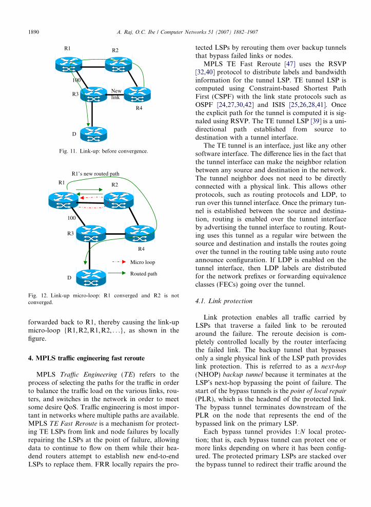
In Fig. 6, external node D is connected to bothR3 and R4. The interior gateway protocol usedwithin an autonomous system does not have thevisibility of this node D. The routers R3 and R4,which are connected to this external node, advertisethe reachability of this node D to the routers in the
R1
D
R3
R2
R4
External device D
Fig. 6. Multihomin
IGP. Since this external destination D is reachablevia two or more nodes, it is referred as a multihomed
(or multihoming) prefix. Multihoming prefixes andtheir backup paths can also create forwarding loops.Fig. 6 shows multihoming networks and their asso-ciated link failure. In Fig. 6, when the link (R3–D)fails, R3 forwards the traffic to node R1. If R1 doesnot know about the failure or if the backup pathtraffic is not differentiated or tunneled through R1,it forwards it back to R3 creating the forwardingloop {R3, R1,R3, R1, . . .}.
Fig. 7 shows multihoming networks and theirassociated node failures. In Fig. 7, the failure ofnode D can create a loop between R3 and R4. Ifthese nodes are external nodes, the ‘‘node’’ versus‘‘link’’ failure may not be detected and thus causesthe forwarding loop. In this case, both R3 and R4detect the link failure and use their backup paths,thereby causing the forwarding loop {R3, R1, R2,R4,R2, R1, R3, . . .}.
In some cases, there may be a network separatingthis multihoming device, which may make it difficultto detect the node failure. In the case of external
Routed path
Backup path
Actual backup path
g link failure.

External device D Routed path
Backup path
R1
D
R3
R2
R4Actual backup path
Fig. 7. Multihoming node failure.
1888 A. Raj, O.C. Ibe / Computer Networks 51 (2007) 1882–1907
nodes, even though a device has multiple links, itmay not have fast reroute capability, and this couldcause more data loss. Additionally, in the followingcases, the same prefix could be attached to two ormore routers:
• The subnet present on a link is advertised fromboth ends of the link.
• Prefixes are propagated from one routing domainto another by multiple routers.
• Prefixes are advertised from multiple routers toprovide resilience in the event of the failure ofone of the routers.
The backup path computation must consider thesecases when it computes the loop-free backup path.
Backup path calculation must also considertopologies that use equal-cost multipaths (ECMP)in the backup path. ECMP is a routing techniquefor routing packets along multiple paths of equalcost. ECMP paths need to be given a special consid-eration. In the absence of an ECMP-specific proce-dure, ECMP paths in a network can create loops
R6
R1 R2 R3
R4R5
Fig. 8. ECMP and
during a fast reroute. When the backup path travelsthrough the ECMP path, the backup path computa-tion procedure must ensure that none of the ECMPpaths makes any forwarding loops during the fastreroute when the backup path is used. For example,in Fig. 8, if all the links have a cost of 1 unit or therouting metric is the hop count, then R1 has threeECMP paths to D, which are {R1, R4,R5, D},{R1,R6, R3,D} and {R1, R2,R3, D}. R3 has thelink (R3–D) protecting backup path {R3, R2,R1,R4, R5, D}. When the link (R3–D) failure occurs,this backup path {R3, R2,R1, R4,R5, D} is usedand traffic is sent up to R1. R1 load balances thetraffic on its three ECMP paths {R1, R4,R5, D},{R1,R6, R3,D} and {R1, R2,R3, D}. Unlike themulticast Reverse Path Forwarding (RPF) [48], inthe unicast routing, the incoming interface is notchecked for loops. When R1 load balances theFRR backup traffic between the ECMP paths, itcreates the forwarding loop {R3, R2, R1,R6,R3, . . .} and the forwarding loop {R3, R2,R1,R2, R3, . . .} as shown in Fig. 8. Therefore, the eachfast reroute mechanism must take special consider-
Routed path
Computed backup path
D
R3
Actual backup path
partial loops.

Routed path
R5
R1
D
R3
R2
R4
Micro loop
Fig. 9. Link down: before convergence.
Routed path
R1’s new routed path R5
R1
D
R3
R2
R4
Micro loop
Fig. 10. Link-down micro-loop: R1 converged and R5 is notconverged.
A. Raj, O.C. Ibe / Computer Networks 51 (2007) 1882–1907 1889
ation for the backup path’s downstream ECMPpaths to avoid forwarding loops.
3.2. FIB inconsistency micro-loops
In a connectionless IP network, routers do notset up end-to-end paths before sending their traffic.Instead, each router makes its own forwarding deci-sions based on its FIB. Each router in the networkremoves a path when a failure is detected on thepath, computes a new path, and installs the newpath independently of the other routers in the net-work. Thus, temporarily the forwarding informa-tion base on these routers may not be consistent.This ‘‘FIB inconsistency’’ can cause forwardingloops during a reroute. FIB inconsistency-basedmicro-loops are acceptable in normal IP reroutingbecause there is no timing restriction for the normalreroute. Also the duration of the disruption causedby the micro-loop is less than that caused by the rec-onvergence. So the additional delay caused bymicro-loops is ignored in the normal IP rerouting.However, micro-loops are not acceptable duringfast reroute. Therefore, micro-loops related to FIBinconsistencies must be eliminated during fastreroute to minimize the data loss.
During fast reroute, when a link-down eventoccurs, the local node detects the failure and enablesthe backup path. The routing protocol then propa-gates the link failure to the remote nodes. However,each node may receive the failure notification at adifferent time, depending upon its location. Also,each node may take a different amount of time tocompute and install the path independently. There-fore, for some period of time, some of the nodesmay have a new path installed and others may havethe old path installed. This means that the link-down event can lead to the formation of micro-loops.
For example, consider Fig. 9. Before the failureof link (R1–R3), node R5’s next hop for destinationD is R1. But when the link (R1–R3) fails, trafficfrom both R1 and R5 is forwarded on the backupnext-hop R2.
If routing at R1 converges and the new next hopis R5, and the routing at R5 converges and the nexthop is R4, then we have a stable system. However, ifR1 converges before R5 and the new next hop at R1is R5, R5 continues to use the old path informationwith R1 as the next hop, R5 will continue to for-ward the traffic from R1 back to R1, thereby caus-ing the ‘‘FIB inconsistency’’ micro-loop {R1, R5,
R1,R5, . . .}, as shown in Fig. 10, until routing atR5 and its downstream nodes converges.
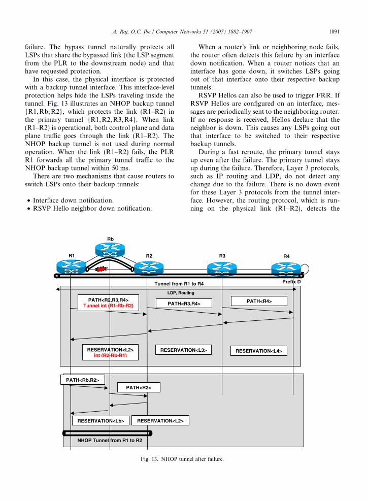
Similarly, FIB inconsistency micro-loops canalso occur during a link-up event. In Fig. 11, whenthe link (R3–R4) comes back up, the different con-vergence times at different routers can create link-up FIB inconsistency micro-loops. When the link(R3–R4) comes up, the ‘‘link-up’’ event is propa-gated to all the nodes in the network. Every routerin the network recomputes the path to its destina-tions and installs the forwarding entries. InFig. 11, the initially routed path at R4 follows thepath {R2, R1, R3,D}. If the link between R4 andR3 comes back up, the routed path at R1 changesback to {R2, R4,R3, D} because of the high costof link (R1–R3).
In Fig. 12, if R1 converges before R2, R1 sendsthe traffic to R2. Because routing at R2 has not con-verged, R2 still points back to R1. The traffic is
Newlink
100
R1
D
R3
R2
R4
Fig. 11. Link-up: before convergence.
R1’s new routed path
Routed path
100
R1
D
R3
R2
R4
Micro loop
Fig. 12. Link-up micro-loop: R1 converged and R2 is notconverged.
1890 A. Raj, O.C. Ibe / Computer Networks 51 (2007) 1882–1907
forwarded back to R1, thereby causing the link-upmicro-loop {R1, R2, R1,R2, . . .}, as shown in thefigure.
4. MPLS traffic engineering fast reroute
MPLS Traffic Engineering (TE) refers to theprocess of selecting the paths for the traffic in orderto balance the traffic load on the various links, rou-ters, and switches in the network in order to meetsome desire QoS. Traffic engineering is most impor-tant in networks where multiple paths are available.MPLS TE Fast Reroute is a mechanism for protect-ing TE LSPs from link and node failures by locallyrepairing the LSPs at the point of failure, allowingdata to continue to flow on them while their hea-dend routers attempt to establish new end-to-endLSPs to replace them. FRR locally repairs the pro-
tected LSPs by rerouting them over backup tunnelsthat bypass failed links or nodes.
MPLS TE Fast Reroute [47] uses the RSVP[32,40] protocol to distribute labels and bandwidthinformation for the tunnel LSP. TE tunnel LSP iscomputed using Constraint-based Shortest PathFirst (CSPF) with the link state protocols such asOSPF [24,27,30,42] and ISIS [25,26,28,41]. Oncethe explicit path for the tunnel is computed it is sig-naled using RSVP. The TE tunnel LSP [39] is a uni-directional path established from source todestination with a tunnel interface.
The TE tunnel is an interface, just like any othersoftware interface. The difference lies in the fact thatthe tunnel interface can make the neighbor relationbetween any source and destination in the network.The tunnel neighbor does not need to be directlyconnected with a physical link. This allows otherprotocols, such as routing protocols and LDP, torun over this tunnel interface. Once the primary tun-nel is established between the source and destina-tion, routing is enabled over the tunnel interfaceby advertising the tunnel interface to routing. Rout-ing uses this tunnel as a regular wire between thesource and destination and installs the routes goingover the tunnel in the routing table using auto routeannounce configuration. If LDP is enabled on thetunnel interface, then LDP labels are distributedfor the network prefixes or forwarding equivalenceclasses (FECs) going over the tunnel.
4.1. Link protection
Link protection enables all traffic carried byLSPs that traverse a failed link to be reroutedaround the failure. The reroute decision is com-pletely controlled locally by the router interfacingthe failed link. The backup tunnel that bypassesonly a single physical link of the LSP path provideslink protection. This is referred to as a next-hop
(NHOP) backup tunnel because it terminates at theLSP’s next-hop bypassing the point of failure. Thestart of the bypass tunnels is the point of local repair
(PLR), which is the headend of the protected link.The bypass tunnel terminates downstream of thePLR on the node that represents the end of thebypassed link on the primary LSP.
Each bypass tunnel provides 1:N local protec-tion; that is, each bypass tunnel can protect one ormore links depending on where it has been config-ured. The protected primary LSPs are stacked overthe bypass tunnel to redirect their traffic around the
A. Raj, O.C. Ibe / Computer Networks 51 (2007) 1882–1907 1891
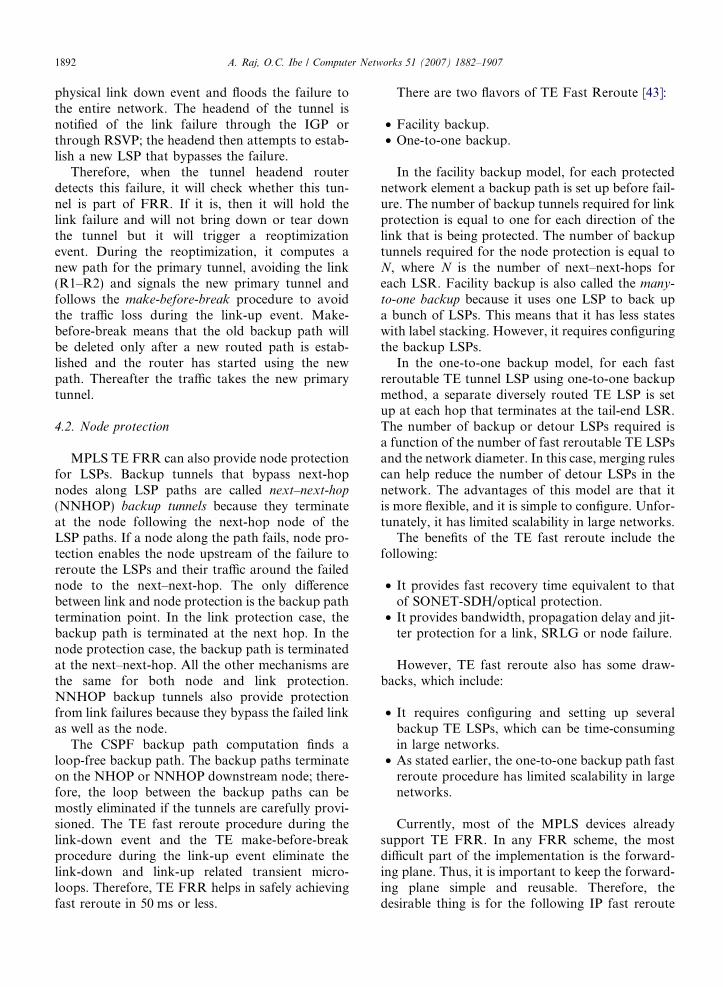
failure. The bypass tunnel naturally protects allLSPs that share the bypassed link (the LSP segmentfrom the PLR to the downstream node) and thathave requested protection.
In this case, the physical interface is protectedwith a backup tunnel interface. This interface-levelprotection helps hide the LSPs traveling inside thetunnel. Fig. 13 illustrates an NHOP backup tunnel{R1, Rb, R2}, which protects the link (R1–R2) inthe primary tunnel {R1,R2, R3,R4}. When link(R1–R2) is operational, both control plane and dataplane traffic goes through the link (R1–R2). TheNHOP backup tunnel is not used during normaloperation. When the link (R1–R2) fails, the PLRR1 forwards all the primary tunnel traffic to theNHOP backup tunnel within 50 ms.
There are two mechanisms that cause routers toswitch LSPs onto their backup tunnels:
• Interface down notification.• RSVP Hello neighbor down notification.
Rb
PATH<R2,R3,R4>Tunnel int (R1-Rb-R2) PATH<R3
RESERVATION<L2>int (R2-Rb-R1)
RESERVATIO
R2R1
Tunnel from R1
LDP, Routi
PATH<Rb,R2>
RESERVATION<Lb>
PATH<R2>
RESERVATION<L2>
NHOP Tunnel from R1 to R2
Fig. 13. NHOP tunn
When a router’s link or neighboring node fails,the router often detects this failure by an interfacedown notification. When a router notices that aninterface has gone down, it switches LSPs goingout of that interface onto their respective backuptunnels.
RSVP Hellos can also be used to trigger FRR. IfRSVP Hellos are configured on an interface, mes-sages are periodically sent to the neighboring router.If no response is received, Hellos declare that theneighbor is down. This causes any LSPs going outthat interface to be switched to their respectivebackup tunnels.
During a fast reroute, the primary tunnel staysup even after the failure. The primary tunnel staysup during the failure. Therefore, Layer 3 protocols,such as IP routing and LDP, do not detect anychange due to the failure. There is no down eventfor these Layer 3 protocols from the tunnel inter-face. However, the routing protocol, which is run-ning on the physical link (R1–R2), detects the
Prefix D
,R4> PATH<R4>
N<L3> RESERVATION<L4>
R3 R4
to R4
ng
el after failure.
1892 A. Raj, O.C. Ibe / Computer Networks 51 (2007) 1882–1907
physical link down event and floods the failure tothe entire network. The headend of the tunnel isnotified of the link failure through the IGP orthrough RSVP; the headend then attempts to estab-lish a new LSP that bypasses the failure.
Therefore, when the tunnel headend routerdetects this failure, it will check whether this tun-nel is part of FRR. If it is, then it will hold thelink failure and will not bring down or tear downthe tunnel but it will trigger a reoptimizationevent. During the reoptimization, it computes anew path for the primary tunnel, avoiding the link(R1–R2) and signals the new primary tunnel andfollows the make-before-break procedure to avoidthe traffic loss during the link-up event. Make-before-break means that the old backup path willbe deleted only after a new routed path is estab-lished and the router has started using the newpath. Thereafter the traffic takes the new primarytunnel.
4.2. Node protection
MPLS TE FRR can also provide node protectionfor LSPs. Backup tunnels that bypass next-hopnodes along LSP paths are called next–next-hop
(NNHOP) backup tunnels because they terminateat the node following the next-hop node of theLSP paths. If a node along the path fails, node pro-tection enables the node upstream of the failure toreroute the LSPs and their traffic around the failednode to the next–next-hop. The only differencebetween link and node protection is the backup pathtermination point. In the link protection case, thebackup path is terminated at the next hop. In thenode protection case, the backup path is terminatedat the next–next-hop. All the other mechanisms arethe same for both node and link protection.NNHOP backup tunnels also provide protectionfrom link failures because they bypass the failed linkas well as the node.
The CSPF backup path computation finds aloop-free backup path. The backup paths terminateon the NHOP or NNHOP downstream node; there-fore, the loop between the backup paths can bemostly eliminated if the tunnels are carefully provi-sioned. The TE fast reroute procedure during thelink-down event and the TE make-before-breakprocedure during the link-up event eliminate thelink-down and link-up related transient micro-loops. Therefore, TE FRR helps in safely achievingfast reroute in 50 ms or less.
There are two flavors of TE Fast Reroute [43]:
• Facility backup.• One-to-one backup.
In the facility backup model, for each protectednetwork element a backup path is set up before fail-ure. The number of backup tunnels required for linkprotection is equal to one for each direction of thelink that is being protected. The number of backuptunnels required for the node protection is equal toN, where N is the number of next–next-hops foreach LSR. Facility backup is also called the many-
to-one backup because it uses one LSP to back upa bunch of LSPs. This means that it has less stateswith label stacking. However, it requires configuringthe backup LSPs.
In the one-to-one backup model, for each fastreroutable TE tunnel LSP using one-to-one backupmethod, a separate diversely routed TE LSP is setup at each hop that terminates at the tail-end LSR.The number of backup or detour LSPs required isa function of the number of fast reroutable TE LSPsand the network diameter. In this case, merging rulescan help reduce the number of detour LSPs in thenetwork. The advantages of this model are that itis more flexible, and it is simple to configure. Unfor-tunately, it has limited scalability in large networks.
The benefits of the TE fast reroute include thefollowing:
• It provides fast recovery time equivalent to thatof SONET-SDH/optical protection.
• It provides bandwidth, propagation delay and jit-ter protection for a link, SRLG or node failure.
However, TE fast reroute also has some draw-backs, which include:
• It requires configuring and setting up severalbackup TE LSPs, which can be time-consumingin large networks.
• As stated earlier, the one-to-one backup path fastreroute procedure has limited scalability in largenetworks.
Currently, most of the MPLS devices alreadysupport TE FRR. In any FRR scheme, the mostdifficult part of the implementation is the forward-ing plane. Thus, it is important to keep the forward-ing plane simple and reusable. Therefore, thedesirable thing is for the following IP fast reroute
A. Raj, O.C. Ibe / Computer Networks 51 (2007) 1882–1907 1893
procedures to reuse as much of the existing forward-ing infrastructure as possible.
5. IP fast reroute
When a router with FRR detects a failure, it usesa set of repair paths in place of the failed component[4], and continues to use these repair paths until thecompletion of the routing transition. Only routersadjacent to the failed component are immediatelyaware of the nature of the failure. The remotedevices detect this failure through normal failurepropagation procedures. Once the routing transitionhas been completed, the router has no further use forthe repair paths because all routers in the networkhave revised their forwarding path and the failedlink has been eliminated from this new path.
Recall that TE FRR uses techniques such asexplicit source-routed end-to-end tunnel, backuptunnel to NHOP or NNHOP, protocol neighborover the tunnel, and make-before-break to addressboth the FRR loops and micro-loops issues. UnlikeTE, IP does not have explicit source-routed tunnelsand protocol neighbors over the tunnel capabilities.The goal of IP FRR is not to create such capabilitiesin the IP network. Instead, it attempts to create analternate FRR with the existing IP functionalitiesand characteristics. This assumption makes it verydifficult to achieve FRR in an IP network.
Since IP does not have the features that are avail-able in the MPLS TE, the following issues need tobe addressed if IP FRR is to be achieved:
• Computing a loop-free backup path.• Detecting multipath FRR loops
– Direct FRR loop detection;– Indirect FRR loop detection.
• Preventing FRR looped path usage or breakingFRR loops.
• Addressing IP-specific FRR cases– Equal Cost MultiPath;– Multihoming;– Non-Broadcast Multiple Access;– Inter-Area.
• Preventing FIB inconsistency-related micro-loops– Link-down micro-loop;– Link-up micro-loop;– Multiple changes and micro-loops.
• Addressing multiple related and unrelatedfailures
– Shared Risk Link Group;– Multiple simultaneous unrelated failures.
• Addressing symmetric and asymmetric networkconfigurations.
In IP fast reroute, many backup path computa-tional procedures are defined and published throughthe IETF. Some of these procedures have someflaws in them or inadequately address the issues dis-cussed in the previous sections. Therefore, theseprocedures are not discussed in this survey. TheIETF IP FRR group and some service providersrequested a non-RSVP TE-based IP FRR mecha-nism. Even though some of the proposals fulfill allthe above FRR requirements specified in the previ-ous section, they use RSVP-TE functionalities toachieve fast reroute. These procedures are also notconsidered in the IETF. In order to limit the scopeof this paper, we only discuss the details of the pro-cedures and techniques that are being considered inthe IETF routing working group.
5.1. IP FRR backup path procedures and their
FRR loop handling
Non-transient FRR loops can be prevented ifloop-free backup path computational proceduresand FRR loop detection procedures are used. Thebackup path computational procedure must con-sider the FRR loop when computing the backuppath, as discussed in the previous section. The‘‘neighbors shortest path’’ (NSP) backup-path com-putational algorithm [20] was the first proposedscheme for computing an IP fast reroute backuppath in IETF. Subsequently, many other backup-path computational procedures [10–15] were pro-posed in the IETF. The following IP FRR backuppath computational procedures are under consider-ation in the IETF:
• Loop-free alternate,• U-turn alternate,• IP fast-reroute using tunnels,• Tunnel to notvia addresses.
Among these backup path computational proce-dures, the loop-free alternate (LFA) procedure isconsidered to be the simplest procedure to implementand the most computationally scalable. Therefore,this procedure is considered to be the baseline pro-cedure for IP fast reroute backup path calculation.By baseline procedure we mean that when a node

1894 A. Raj, O.C. Ibe / Computer Networks 51 (2007) 1882–1907
supports the IP FRR, this LFA procedure is used firstto compute the backup path. In the absence of LFAbackup path, nodes can use other advanced backuppath computational procedures. The LFA procedurecannot achieve 100% protection coverage. Protectioncoverage means that when a link or node fails, thereexists a loop-free backup path to protect that failure.Simulations show that the LFA procedure has closeto 80% protection coverage [49]. This means that80% of the failures can be addressed by the LFAbackup path computational procedures. However,the coverage is highly topology dependent. Toaddress the remaining 20% protection coverage,additional advanced backup-path computationalprocedures, such as U-turn alternate, IP fast rerouteusing tunnels, and notvia tunnel procedures are pro-posed. The following sections provide detaileddescription of these procedures.
Among the advanced IP FRR procedures, thetunnel-based procedures provide greater control ofthe repair path. However, this is achieved at a pricebecause IP tunnels are created with extra encapsula-tion on the IP packet. Different types of IP tunnelsuse different encapsulations, and these tunnels areusually provisioned or signaled. Therefore, tunnelsneed extra encapsulation processing and extra pay-load. The tunnel can be either an IP tunnel orLDP tunnel. Some of the traffic types need tunnel-ing, even in the absence of IP FRR. For example,Layer 3 VPN traffic needs either an MPLS orL2TPv3 [23] tunnel. In this case, the additional tun-nel can be the same MPLS or L2TPv3 type tunnelfor IP FRR. Most tunnel-based IP FRR proceduresdo not require any changes in the forwarding dataplane. If the LDP tunnels are used for IP FRRbackup path tunnels, it is also possible to achieveLDP FRR with the same backup paths.
5.1.1. IP FRR using loop-free alternate
A loop-free alternate backup path must not con-tain a node that the traffic has already visited. Aloop-free alternate is a next-hop that is not a primarynext-hop. Also, the shortest path to the destinationfrom the alternate neighbor must not go backthrough the upstream router that forwarded the traf-fic or any upstream router that could forward it back.
5.1.1.1. Loop-free criterion. A neighbor N can pro-vide a loop-free alternate (LFA) path for sourcenode S and destination node D if [16]:
DoptðN;DÞ < DoptðN; SÞ þ DoptðS;DÞ;
where Dopt(N,D) is the shortest path from router’sinterior gateway protocol neighbor N to the destina-tion D, Dopt(S, D) is the shortest distance from thecalculating source router S to the destination D,and Dopt(N,S) is the shortest distance from the rou-ter’s IGP neighbor N to itself S.
A sub-set of loop-free alternates are downstreampaths, which must meet the more restrictive condi-tion of downstream path criterion.
5.1.1.2. Downstream path criterion. A neighbor Ncan provide an LFA downstream path if
DoptðN;DÞ < DoptðS;DÞ:
A path satisfying this condition is also known asdownstream path or feasible alternate.
For link protection, the LFA algorithm avoidsthe pseudo-node (if any) on the primary next hopfrom the computing router to the next hop router.A pseudo-node is a broadcast link with zero-costlinks connecting it to other nodes. Strictly they arezero cost from the pseudo-node, but non-zero tothe pseudo-node.
In Fig. 14, link (R4–D) is a high-cost link. There-fore, R2 has a routed path {R2, R4,R3, D}. In thefigure, for the link (R1–R3) protection, the alternatepath must avoid the point of local repair (PLR) nodeR1. As defined earlier, a PLR is a router that detectsthe local failure and installs the FRR computedbackup path. The routed path from R2 to D avoidsthe PLR node R1. This satisfies the LFA condition.Therefore, R1 can use the LFA backup path{R2,R4, R3,D} for link (R1–R3) protection atR1. Fig. 14 shows this link-protecting backup pathfor the link (R1–R3). In this case, R4’s direct link(R4–D) is a higher cost link, so the traffic goesthrough the next hop R3 to get to D.
For LFA node protection, the node simplyavoids the primary next-hop neighbor. Fig. 15shows the node-protecting backup path for nodeR3.
An FRR loop can occur when a link-protectingbackup path is used for node protection, as shownin Figs. 1 and 2. Therefore, a loop-free link-protect-ing alternate can create a FRR loop when a nodefailure occurs. LFA requires that the link-protectingalternate be downstream path Dopt(N,D) < Dopt
(S, D). This generally avoids the potential for theseloops. However, this may substantially reduce cov-erage. Alternatively, other node protectionprocedures, such as Non-Stop Routing (NSR) [44]or Graceful Restart (GR) [45] can be used for the

R2
Routed path
Backup path
R1
D
R3R4
Actual backup path
Fig. 15. LFA node failure handling.
3
Routed path
Backup path
R1
D
R3
R2
R4
Actual backup path
Fig. 14. LFA link failure handling.
A. Raj, O.C. Ibe / Computer Networks 51 (2007) 1882–1907 1895
node protection. A node operating in NSR moderecovers all its state information from a local data-base after the restart. Hence, neighbors do not knowabout the node restart. A node operating in GRmode recovers some or all the information fromits neighbors after the restart. Therefore, neighborsare aware of the restart and they participate in therecovery. In these models, the forwarding planehas not failed, and hence it can forward normally.It is only the control plane that has failed, and thecontrol plane is reconstructed without disturbingthe forwarding plane. In both modes, it is possibleto handle the node failures with little or no trafficloss, depending upon the hardware.
Similarly, if there is an SRLG failure and thebackup path does not protect against that SRLGfailure, then forwarding FRR loops can occur. Thiscan happen when the actual failure is more extensivethan the computed backup-path protection. TheLFA procedure normally requires one shortest path
first (SPF) rooted at each neighbor of S, plus onereverse SPF rooted at S. Additional SPFs arerequired for handling SRLGs. An LFA backuppath can only address the SRLG protection forthe area within which it is computed. If an SRLGcontains links from multiple areas, it is possible
for traffic to leave one area and then be forwardedacross a path that includes the SRLG in the nextarea.
The loop-free alternate has the following restric-tions [46] and capability limitations:
• Loop-free alternates must not be used in theOSPF [24,29] backbone area if there are any vir-tual links configured, unless for each area that avirtual link transits, there is a full mesh of virtuallinks between all area border routers (ABRs) inthat area.
• Loop-free alternates must not be used in anOSPF area that contains more than one alternateABR.
• Loop-free alternates must not be used for auton-omous system (AS) external routes or autono-mous system border routers (ASBR) routes in anon-backbone area of a network where thereexists an ABR that is announced as an ASBRin multiple non-backbone areas and there existsanother ABR that is in at least two of the samenon-backbone areas.
• Loop-free alternates must not be used in a non-backbone area of a network for AS externalroutes, where an AS external prefix is advertised
R1 10 Primary Next hop
5
5
10
P
D
R2
U-turn alternate
5S
U-turn Alternate Next hop
Fig. 16. U-turn alternate.
1896 A. Raj, O.C. Ibe / Computer Networks 51 (2007) 1882–1907
with the same type of external metric by multipleASBRs that are in different non-backbone areas,with a forwarding address of 0.0.0.0 or by one ormore ASBRs with forwarding addresses in multi-ple non-backbone areas when an ABR existssimultaneously in two or more of those non-backbone areas.
• This mechanism does not work in ring topologiesand only works for the networks such as trianglesof nodes. This is because this only provides therepairs with a range of 1 or 2 hops.
• This is a partial solution and only works for verylimited topologies. However, with this topologydependency, a network can be carefully con-structed to provide a good repair coverage. Butthe failure of a single link or node can convertthe network into one with poor coverage for sub-sequent failures.
In summary, when only the downstream paths areused as backup paths, FRR loops may be elimi-nated in the LFA. This further reduces the protec-tion coverage severely for the LFA procedure.Thus, LFA is not a complete solution.
5.2. IP FRR using U-turn alternate
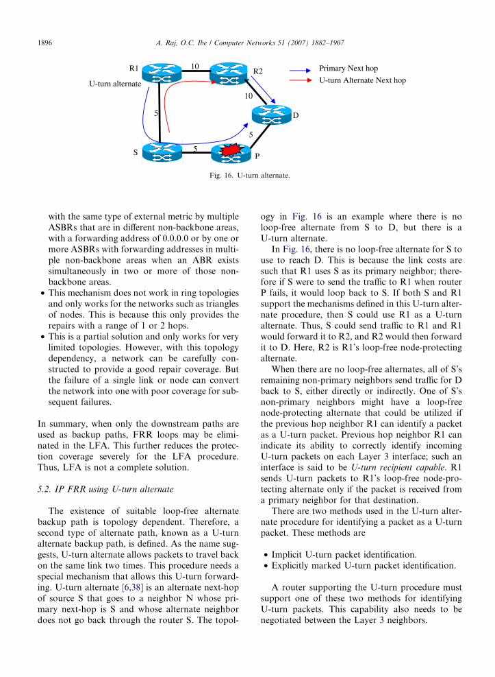
The existence of suitable loop-free alternatebackup path is topology dependent. Therefore, asecond type of alternate path, known as a U-turnalternate backup path, is defined. As the name sug-gests, U-turn alternate allows packets to travel backon the same link two times. This procedure needs aspecial mechanism that allows this U-turn forward-ing. U-turn alternate [6,38] is an alternate next-hopof source S that goes to a neighbor N whose pri-mary next-hop is S and whose alternate neighbordoes not go back through the router S. The topol-
ogy in Fig. 16 is an example where there is noloop-free alternate from S to D, but there is aU-turn alternate.
In Fig. 16, there is no loop-free alternate for S touse to reach D. This is because the link costs aresuch that R1 uses S as its primary neighbor; there-fore if S were to send the traffic to R1 when routerP fails, it would loop back to S. If both S and R1support the mechanisms defined in this U-turn alter-nate procedure, then S could use R1 as a U-turnalternate. Thus, S could send traffic to R1 and R1would forward it to R2, and R2 would then forwardit to D. Here, R2 is R1’s loop-free node-protectingalternate.
When there are no loop-free alternates, all of S’sremaining non-primary neighbors send traffic for Dback to S, either directly or indirectly. One of S’snon-primary neighbors might have a loop-freenode-protecting alternate that could be utilized ifthe previous hop neighbor R1 can identify a packetas a U-turn packet. Previous hop neighbor R1 canindicate its ability to correctly identify incomingU-turn packets on each Layer 3 interface; such aninterface is said to be U-turn recipient capable. R1sends U-turn packets to R1’s loop-free node-pro-tecting alternate only if the packet is received froma primary neighbor for that destination.
There are two methods used in the U-turn alter-nate procedure for identifying a packet as a U-turnpacket. These methods are
• Implicit U-turn packet identification.• Explicitly marked U-turn packet identification.
A router supporting the U-turn procedure mustsupport one of these two methods for identifyingU-turn packets. This capability also needs to benegotiated between the Layer 3 neighbors.

A. Raj, O.C. Ibe / Computer Networks 51 (2007) 1882–1907 1897
Implicit U-turn packet identification requires nomodification to the packets sent into the U-turnalternate. Consider an interface or subinterface thatis identified as being able to identify received U-turnpackets. Assume that the router receives a packet fordestination D from the primary neighbor to whomthe router would normally forward the packet. Thenthe router locally identifies the packet as a U-turnpacket and forwards it on the loop-free alternate.In essence, this breaks the single-hop forwardingloops. This procedure normally requires a specialinterface-specific reverse path forwarding verifica-tion, similar to the one used in the multicast routing.
Explicitly marked U-turn packet identificationrequires that the router directing the packet to theU-turn alternate mark the U-turn packets explicitlyas such. Explicitly marking U-turn traffic has thefollowing disadvantages, which could be viewed asadvantages for the implicit U-turn traffic:
• A marking method must be selected. This mark-ing needs to be below Layer 3 since there are noavailable bits for this purpose in the IPv4 header.
• In some cases, implicit U-turn marking mitigatesloops that form by detecting the loop and for-warding packets to a loop-free node-protectingalternate. This capability is lost when packetsare explicitly marked.
There are a number of ways to mark U-turnpackets. For example, this could be done at Layer2 by using different PPP types, Ethernet types, etc.The simplest mechanism that can apply, regardlessof the Layer 2 technology, is to use a well-knownMPLS label, referred to as a U-turn Label.
The following procedure provides the U-turnalternate path selection algorithm:
For each destination D, the following criteriaapply:
1. Neighbor N has indicated that it can break U-turns for traffic coming in an interface.
2. Neighbor N has a loop-free node-protectingalternate to reach the destination D and it avoidsthe router S’s primary neighbor P.
3. If a loop-free node-protecting alternate is avail-able, select it for use.
4. If not, pick among loop-free link-protectingalternates and U-turn alternates as desired.
U-turn alternate procedure has the followingrequirements and limitations:
• The U-turn alternate procedure considers onlysingle hop U-turns. When the U-turn is per-formed, the receiving node must have an LFApath to the destination. Otherwise the neighborcannot be used as a U-turn neighbor. Therefore,the protection coverage is still topology-dependent.
• U-turn alternates require a link capability sub-TLV (Type Length Value) signaling extensionfor both ISIS [7] and OSPF [8].
• The computational complexity of the U-turnalternate is on the order of alternate capableneighbors, O(alternate-capable neighbors).
• Packets sent to the alternate next-hop requireadding a single U-turn label. This needs to beremoved at the next hop.
• Forwarding look-up complexity is comparable tothe mechanisms, such as Reverse Path Forward-ing (RPF), Virtual Route Forwarding (VRF),Policy-based forwarding, used in the forwarding.However, this requires a change in existing for-warding paradigm, which makes it difficult to ret-rofit to existing hardware.
• When an LFA-based backup path is available,this procedure always uses the LFA-basedbackup paths. Therefore, this procedure requiresan LFA backup path computational procedurealso. This means that most of the limitations thatare applicable to an LFA procedure are alsoapplicable to U-turn procedures.
• This mechanism does not work in the ring topol-ogies and only works for the networks such as tri-angles of nodes. This is because it only providesthe repairs with a range of 1 or 2 hops. This pro-cedure only provides limited protection coverage.The current coverage results are based on specifictopologies.
• This is a partial solution and only works for lim-ited topologies. The main reason that peoplewant fast-reroute is to give a service guarantee.The problem with partial repair coverage is thatyou can only make this guarantee to a subset ofyour customers, and it is quite difficult to predictwhich subset this is, and that may change withsmall changes to the topology. It is also quitehard to manipulate the topology to give goodcoverage to a specific customer.
The loop-free alternate (LFA) procedure by itselfdoes not provide adequate coverage for the trafficbetween all the source–destination pairs. As withloop-free alternates, the existence of suitable U-turn

1898 A. Raj, O.C. Ibe / Computer Networks 51 (2007) 1882–1907
alternates is also topology dependent. However,simulations with various service provider networkshave shown that the combined LFA and U-turnprocedures extend the protection coverage abovethat seen with just LFA procedure. Since this proce-dure also does not address all the topologies, this isnot sufficient solution for deploying the IP fastreroute.
5.3. IP fast-reroute using tunnels
This procedure uses IP tunnels for achieving lim-ited directed forwarding [3]. The directed forward-ing refers to the ability at the tunnel end point(decapsulation point) to specify which next-hopshould be used for forwarding the native packet,rather than the normal one indicated by a lookupof the destination address in the FIB. Therefore,directed forwarding permits a router to specify thetunnel egress where to forward traffic. This tunnelencapsulation could be an MPLS label encapsula-tion. When IP or MPLS tunnels are used as repairpaths, the repair strategies described in this proce-dure operate on the basis that if a packet can some-how be sent to the other side of the failure or can bedropped at a point where it can reach the other side,it will subsequently proceed towards its destinationexactly as if it had traversed the failed component,as shown in Fig. 17.
Creating a repair path from S to E may require apacket to traverse an unnatural route. If a suitablenatural path starts at a neighbor, then S can forcethe packet directly there. If this is not the case, thenS may create one by using a tunnel to carry thepacket to a point in the network where there is a realloop-free alternate. Note that the tunnel does nothave to go from S to E; it can terminate at any rou-ter in the network, provided that S can be sure thatthe packet will proceed correctly to its destinationfrom that router. Since it is not easy for a router
5
R1
Tunnel
5
10
S
5
Fig. 17. Link repair
to immediately distinguish between a link failureand the failure of its neighbor, repair paths are cal-culated in anticipation of adjacent router failure.
There are number of IP tunnel mechanisms thatmay be used to fulfill the requirements of thisdesign. Suitable candidates include IP-in-IP [21],GRE [22] and L2TPv3 [23]. The selection of the spe-cific tunneling mechanism and any necessaryenhancements used to provide a repair path is out-side the scope of this paper.
Repair paths are pre-computed in anticipation oflater failures so they can be promptly activatedwhen a failure is detected. Three types of repairpaths are used to achieve the repair:
1. Equal cost path-split;2. Loop-free Alternate;3. Tunnel.
The operation of equal cost path-split and loop-free alternate is described in [16]. A tunneled repairpath tunnels traffic to some staging point from whichit will travel to its destination using normal forward-ing without looping back. The repair path can bethought of as providing a virtual link, originatingat a router adjacent to a failure, and diverting trafficaround the failure. This is equivalent to providing avirtual loop-free alternate to supplement the physi-cal loop-free alternates. In general, the propertiesthat are required of tunnel endpoints are
• The end point must be reachable from the tunnelsource without traversing the failed link.
• When released, tunneled packets will proceedtoward their destination without being attractedback over the failed link or node.
For source router S that is trying to determinetunneled repair paths around a neighboring routerE, the set of potential tunnel end points includes
R2
D
E
Primary Next hop
Alternate path
with tunnels.

A. Raj, O.C. Ibe / Computer Networks 51 (2007) 1882–1907 1899
all the routers that can be reached from S using nor-mal forwarding without traversing the failed link S–E. This is termed the ‘‘F-space’’ of S with respect tothe failure of E. The set of possible release pointscan be determined by computing the set of routersthat can reach the repair path target without tra-versing the failed link. This is termed the ‘‘G-space’’of the target with respect to the failure. The G-spacecan be obtained by computing a reverse shortestpath tree (rSPT) rooted at the repair path target,with the sub-tree that traverses the failed link (ornode) excised. The rSPT uses the cost towards theroot rather than from it and yields the best pathstowards the root from other nodes in the network.The intersection of the target’s G-space with S’sF-space includes all the possible release pointsfor any repair path not employing directedforwarding.
IP fast-reroute using tunnels has the followingrequirements and limitations:
• A tunnel-based backup procedure requires thefollowing enhancements to routing protocols:1. The ability to advertise IP FRR capability.2. The ability to advertise tunnel endpoint
capability.3. The ability to advertise directed forwarding
identifiers.
• Multiple concurrent failures other than thosethat occur due to the failure of a single routerare not addressed.
• Shared risk group protection is not considered.However, this procedure can trivially be trimmedto exclude SRLG traversals. But the resultantconnectivity may require a secondary repairanalysis.
• Because the mechanisms described here rely oncomplete topological information from the linkstate routing protocol, they will only work withina single link state flooding domain.
• Reverse Path Forwarding (RPF) checks cannotbe used in conjunction with IP FRR. This isbecause the use of tunnels may result in packetsarriving over different interfaces than expected.
• This procedure requires one reverse SPF (rSPF)path per neighbor and one rSPF path per neigh-bor’s neighbor.
• Multiple encapsulations may be required:1. A directed forwarding label;2. An IP header to reach final waypoint;3. A second IP header to get to the middle
waypoint;
4. More waypoints may be required for SRLGand node protection;
5. An extra tunnel for multihomed prefixes.
• This procedure requires the ability to remove IPheaders and perform two lookups. Some of thiscan be mitigated by the use of MPLS penultimatehop popping.
5.4. IP FRR using tunnel to notvia addresses
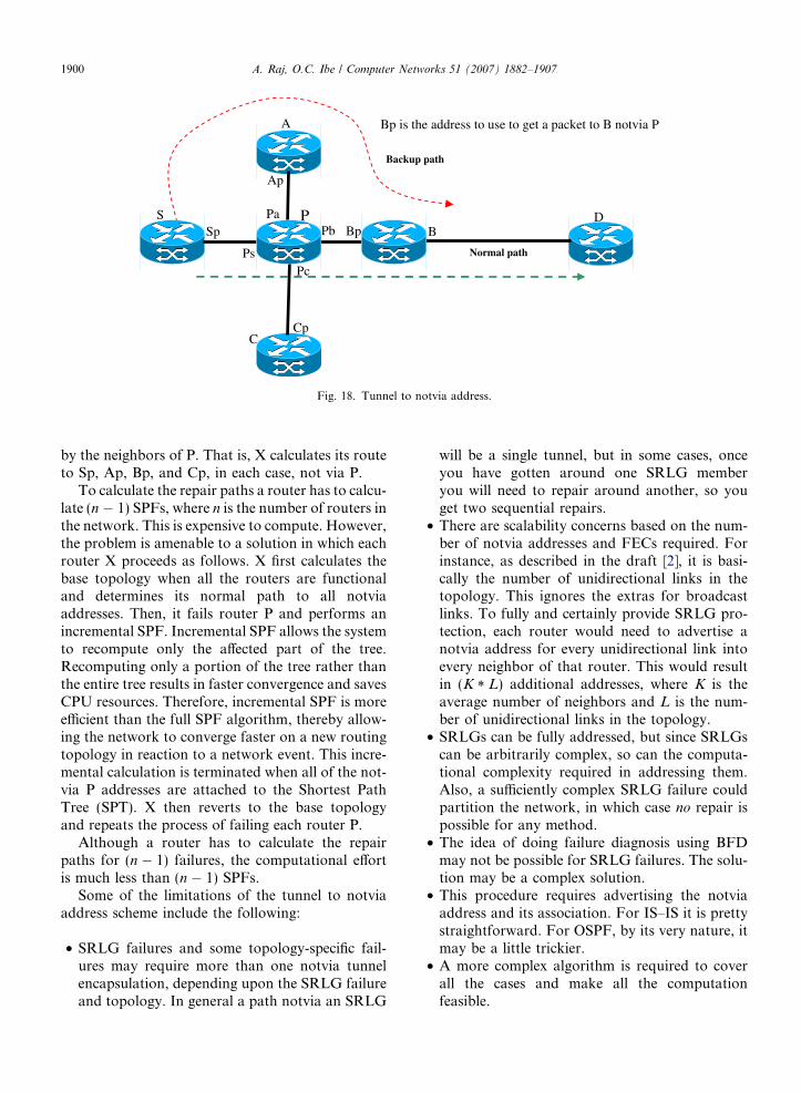
In its simplest form, this repair mechanism worksby assigning an additional address to each interfacein the network. This additional address is called thenotvia address. The semantics of a notvia addressare that a packet addressed to a notvia address mustbe delivered to the router with that address, not viathe neighboring router on the interface to whichthat address is assigned [2]. To repair a failure, therepairing router encapsulates the packet to a notviaaddress of the router interface on the far side of thefailure. The routers on the repair path then know towhich router they must deliver the packet, andwhich network component they must avoid.
For example, assume that S has a packet for desti-nation D that it would normally send via P and B, andthat S suspects that P has failed. S encapsulates thepacket to Bp, the interface of B that connects to P.The path from S to Bp is the shortest path from Sto B, not going via P. If the network contains a pathfrom S to B that does not use router P, then the packetwill be successfully delivered to B. When the packetaddressed to Bp arrives at B, B removes the encapsu-lation and forwards the repaired packet towards itsfinal destination. This is illustrated in Fig. 18.
Note that a packet may back track after theencapsulation is removed. However, because thede-encapsulating router is always closer to the pack-et’s destination than the encapsulating router, thepacket will not loop. The notvia repair mechanismrequires that all routers on the path from S to B,as shown in Fig. 18, have a route to Bp. They cancalculate this by failing node P, running an SPF,and finding the shortest route to B.
Unfortunately, a router has no simple way ofknowing whether it is on the shortest path for anyparticular repair. It is therefore necessary for everyrouter to calculate the path it would use during arouter failure. In other words, again with referenceto Fig. 18, some router X will consider each routerin turn to be P, fail P, and then calculate its ownroute to each of the notvia P addresses advertised
CCp
P
Pc
BD
C
Pb
Ap
Pa
A
S
Bp is the address to use to get a packet to B notvia P
Normal path
Backup path
BpSp
Ps
Fig. 18. Tunnel to notvia address.
1900 A. Raj, O.C. Ibe / Computer Networks 51 (2007) 1882–1907
by the neighbors of P. That is, X calculates its routeto Sp, Ap, Bp, and Cp, in each case, not via P.
To calculate the repair paths a router has to calcu-late (n � 1) SPFs, where n is the number of routers inthe network. This is expensive to compute. However,the problem is amenable to a solution in which eachrouter X proceeds as follows. X first calculates thebase topology when all the routers are functionaland determines its normal path to all notviaaddresses. Then, it fails router P and performs anincremental SPF. Incremental SPF allows the systemto recompute only the affected part of the tree.Recomputing only a portion of the tree rather thanthe entire tree results in faster convergence and savesCPU resources. Therefore, incremental SPF is moreefficient than the full SPF algorithm, thereby allow-ing the network to converge faster on a new routingtopology in reaction to a network event. This incre-mental calculation is terminated when all of the not-via P addresses are attached to the Shortest PathTree (SPT). X then reverts to the base topologyand repeats the process of failing each router P.
Although a router has to calculate the repairpaths for (n � 1) failures, the computational effortis much less than (n � 1) SPFs.
Some of the limitations of the tunnel to notviaaddress scheme include the following:
• SRLG failures and some topology-specific fail-ures may require more than one notvia tunnelencapsulation, depending upon the SRLG failureand topology. In general a path notvia an SRLG
will be a single tunnel, but in some cases, onceyou have gotten around one SRLG memberyou will need to repair around another, so youget two sequential repairs.
• There are scalability concerns based on the num-ber of notvia addresses and FECs required. Forinstance, as described in the draft [2], it is basi-cally the number of unidirectional links in thetopology. This ignores the extras for broadcastlinks. To fully and certainly provide SRLG pro-tection, each router would need to advertise anotvia address for every unidirectional link intoevery neighbor of that router. This would resultin (K * L) additional addresses, where K is theaverage number of neighbors and L is the num-ber of unidirectional links in the topology.
• SRLGs can be fully addressed, but since SRLGscan be arbitrarily complex, so can the computa-tional complexity required in addressing them.Also, a sufficiently complex SRLG failure couldpartition the network, in which case no repair ispossible for any method.
• The idea of doing failure diagnosis using BFDmay not be possible for SRLG failures. The solu-tion may be a complex solution.
• This procedure requires advertising the notviaaddress and its association. For IS–IS it is prettystraightforward. For OSPF, by its very nature, itmay be a little trickier.
• A more complex algorithm is required to coverall the cases and make all the computationfeasible.

A. Raj, O.C. Ibe / Computer Networks 51 (2007) 1882–1907 1901
Even though the notvia tunnel procedure hassome deficiencies, at a high level it seems to be betterthan the other competing procedures.
5.5. IP FRR FIB inconsistency micro-loop handling
Up until now we have considered variousbackup-path computational procedures and theirFRR loop handling. In this section, we considertransient micro-loops related to distributed comput-ing and forwarding database inconsistencies. Tran-sient micro-loops are formed during the periodswhen a network is reconverging following a topol-ogy change, and are caused by inconsistent FIBsin the routers.
In the network, FIB inconsistency can resultfrom the following events [34]:
1. Component failure,2. Component repair,3. Management withdrawal of a component,4. Management insertion of a component,5. Management change of link cost (either positive
or negative),6. External cost change, such as changing external
gateway as a result of a BGP change,7. An SRLG failure.
In each case, a component may be a link or arouter.
As stated earlier, micro-loops may occur over asingle link between a pair of routers that have eachother as the next hop for a prefix. They may alsoform when a cycle of routers is configured such thateach router has the next router in the cycle as thenext hop for a given prefix [1]. Cyclic micro-loopsalways include at least one link with an asymmetriccost, and/or at least two symmetric cost link costchanges [1].
Both FRR loops and micro-loops have twoundesirable side-effects: congestion and repair star-vation. A looping packet consumes bandwidth untilit escapes as a result of the resynchronization of theFIBs or until its time to live (TTL) expires. Thistransiently increases the traffic over a link by asmuch as 128 times [1], and may cause the link tobe congested. As a result of this, ‘‘innocent’’ trafficusing the link experiences increased latency and isliable to congestive packet loss.
FIB inconsistency is usually independent of thebackup path computation procedure. Therefore, it
is possible to have a solution that is common toall types of backup paths.
FIB inconsistency micro-loops have the follow-ing properties:
• Independent decisions can cause micro-loops.• Loops may occur between pairs of nodes or
cycles of nodes.
The following solutions have been proposed forhandling micro-loops [1]:
• Incremental cost change;• Ordered SPF or Ordered FIB installation
(OFIB);• Synchronized FIB installation;• Tunnel-based approach
– Single tunnel per router;– Distributed tunnels;
• Path-locking via safe neighbors (PLSN);• Loop-less Interface Specific forwarding (LISF).
In the incremental cost change procedure [1],when a link fails, the cost of the link is generallychanged from its assigned metric to ‘‘infinity’’.However, if the link cost is increased in suitableincrements, and the network is allowed to stabilizebefore the next cost increment is advertised, thenno micro-loops form. Once the link cost has beenincreased to a value greater than that of the lowestalternative cost around the link, the link may be dis-abled without causing a micro-loop. Even thoughthe procedure is simple, incremental cost changecannot be used because of its excessively long net-work convergence time [18].
In the ordered SPF procedure [1], a strict order-ing ensures that nodes closer to the root always pro-cess the failure after any nodes further away. Hence,micro-loops are prevented. When the failure hasbeen announced, each router waits a multiple ofsome time delay value. The multiple is determinedby the node’s position in the reverse spanning tree,and the delay value is chosen to guarantee that anode can complete its processing within this time.This imposes a delay that is bounded by the net-work diameter.
The ordered SPF mechanism requires all nodes inthe domain to operate according to these proce-dures, and the presence of non-cooperating nodescan give rise to loops for any traffic that traversesthem. Without additional mechanisms, these loopscould remain in place for a significant time. In

1902 A. Raj, O.C. Ibe / Computer Networks 51 (2007) 1882–1907
ordered SPF or ordered FIB installation, for anylink or node change, the scheme finds a safe order-ing for FIB installation. Each router computes its‘‘rank’’ with respect to the change. Delays for theinstallation time are proportional to its rank. Theo-retically, ordered FIB installation has the advantagethat it provides complete coverage for all micro-loops, including those that are due to asymmetriclink cost [18]. This method also works with SRLGs;however, this may require different delays for differ-ent sets of prefixes. The disadvantage of orderedFIB installation is that the worst-case network con-vergence time depends on the diameter of the net-work and this can be quite long. More details canbe found in [50], which proposes a mechanism toprevent transient loops during non-urgent topologychanges by ordering the FIB updates on routers innetworks that use link state routing protocols.
In synchronized FIB installation approach [1],there would be two FIBs, a new and old FIB oneach device. In this case, FIB inconsistency isremoved with a synchronized action throughoutthe network, to switch from the old to the newFIB. The FIB swap time can be signaled or com-puted based on synchronized network time protocol(NTP). Even though this procedure is conceptuallysimple with minimal signaling, it has drawbacksthat include strong implementation constraints,dependence on NTP, and the fact that traffic lossdue to loops would only be minimized and not elim-inated [18].
The single tunnel per router mechanism [1] worksby creating an overlay network using tunnels whosepaths are not affected by the topology change andcarrying the traffic affected by the change in thatnew network. Distributed Tunnels [1] procedure issimilar to the single tunnel per router approach,except that all micro-loop preventing routers calcu-late a set of link failure paths. The attractive prop-erties of this method include its ability to cover allcases, and independence of transition time fromthe size of the network. On the other hand, thismethod requires modifications to the routing proto-col to support ‘‘covert’’ topology change announce-ment. Also, using tunneling introduces differentoperational and security considerations, and the dis-tributed version of the method involves relativelyhigher level of complexity.
In the path locking via safe neighbor procedure[1], the safe neighbor is computed to be used as atransitional next-hop. A safe neighbor is a neighborthat is loop-free on the old topology and is on a
downstream path on new topology. If two neigh-boring routers do not have a safe neighbor, amicro-loop can form on that link and local micro-loops are also possible with non-supporting routers.The path locking via safe neighbor first installs asafe neighbor as primary next-hop. The schemehas a fixed convergence time, regardless of networksize. Also, it works regardless of the topologychanges that have occurred, which means that itprovides SRLG protection. However, the coverageis dramatically reduced with SRLGs. Analysis ofexisting networks shows that with the scheme about90% of the potential two-hop micro-loops are elim-inated [17,18]. The disadvantages of path lockingvia safe neighbors are as follows:
• It does not provide 100% micro-loop preventioncoverage.
• It requires per prefix installation of repair pathsin the FIB. Therefore, it is only suitable for thebasic LFA and U-turn procedures.
• As with the basic IP FRR mechanism, increasingredundancy in network topology can be used toincrease micro-loop coverage. However, without100% coverage, even traffic that is micro-loopfree may suffer congestion or loss due to the traf-fic across a link that is not micro-loop free.
• It may reduce the protection coverage. Whenusing PLSN in conjunction with U-turns or oneof the non-100% coverage repair solutions, thenapproximately 20% of the traffic that would becorrectly repaired will be disrupted by micro-loops, thus effectively negating the repairs inthose cases.
• Prevention of multihop micro-loops in networkswith asymmetric link costs requires a stricterneighbor safety condition (downstream pathbefore topology change), which reduces the cov-erage below the anticipated 90%. In theory, pathlocking can be augmented in a number of ways(requiring a different forwarding mechanism) toprovide 100% coverage. However, in practice itis not clear how it can be done. The proceduresto handle the advanced backup path calculationare not defined at this time.
As stated earlier, the main reason that service pro-viders want fast-reroute is to give a service guaranteeand sell different services. The problem with partialcoverage is that you can only make this guaranteeto a subset of destinations, and it is quite difficultto predict which subset this is, and that may change

A. Raj, O.C. Ibe / Computer Networks 51 (2007) 1882–1907 1903
with small changes to the topology. It is also quitehard to manipulate the topology to give good cover-age to a specific customer. This makes it very difficultto sell service guarantees to different customers.
When all the routers in a network have the sameview of the network, there would be no forwardingloop. It is only in the presence of discrepancies inthe views of different routers that a packet might becaught in a loop. However, in such a case, underinterface-specific forwarding, the packet would havearrived through an unusual interface of at least oneof the routers involved in the loop. So, a forwardingloop can be avoided if the packet were to be dis-carded in such a scenario rather than forwarded tothe usual next hop. This approach of avoiding for-warding loops by selectively discarding packets thatarrive through unusual interfaces is referred to asLoop-less Interface Specific forwarding (LISF) [35].The procedure is not suitable for most fast reroutemechanisms because usually in the fast reroutemechanism the remote receiving router does notknow about the ingress interface during the fastreroute and discarding the packets defeats thepurpose.
Most of the above mechanisms require one ormore convergence delay timers that must have aduration that is consistent throughout the routingdomain. This time is the worst case time that any
Table 1Micro-loop solution summary
Procedure Pros Cons
Incremental costchange
Only local routerneeds to support theprocedure
Unacceptable delay (
Ordered SPFs Control planeprocedure
SRLGs require destiimplementation diffeTraffic loops minimi
Synchronized FIBinstallation
This procedure lookssimple
Implementation is nomay cause loops. NTTraffic loops are min
Tunnel-basedapproach
Network size has littleor no impact
This procedure requisupport ‘‘covert’’ toptunnel introduces diffsecurity concerns
Path Locking viasafe neighbors(PLSN)
Deals with SRLGsand uncorrelatedchanges
Completeness dependmechanisms. It is nomicro-loops in all IP
Loop-less Interfacespecificforwarding (LISF)
Looks simple This is not suitable foreroute receiving rouinterface during fast
router will take to calculate backup path, and tomake the necessary changes to the FIB.
The timer synchronization mechanism must havethe following properties [9]:
• The convergence delay time must be consistentfor all routers that are converging on the newtopology.
• The convergence delay time must be the highestdelay required by any router in the new topology.
• The mechanism must increase the delay when anew router is introduced to the network thatrequires a higher delay than is currently in use.
• When the router that had the longest delayrequirements is removed from the topology, theconvergence delay timer value must, within somereasonable time, be reduced to the longest delayrequired by the remaining routers.
• It must be possible for a router to change theconvergence delay timer value that it requires.
• A router that is in multiple routing areas or isrunning multiple routing protocols may signal adifferent loop-free convergence delay for eacharea and for each protocol.
A router that dynamically determines its pro-posed timer value must do so in such a way that itdoes not cause the synchronized value to continually
Delay (in FIB compute/install)
bounded, but can be very high) Unacceptably high(bounded by maximummetric used)
nation-based decision. Multivendorrences may cause loop problems.zed not eliminated
High (bounded bynetwork diameter)
t trivial. Synchronization variancesP dependence and resolution issues.imized not eliminated
Minimal
res routing protocol changes toology change announcement. Also,erent complexity, operational and
Minimal
s on additional forwardingt clear if this procedure eliminatesFRR mechanisms
Comparatively small
r most fast reroute mechanisms. Theter does not know about the ingressreroute
Comparatively small
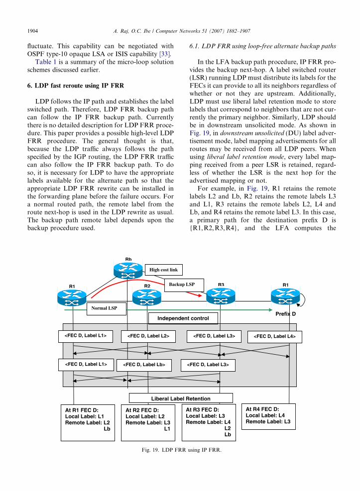
1904 A. Raj, O.C. Ibe / Computer Networks 51 (2007) 1882–1907
fluctuate. This capability can be negotiated withOSPF type-10 opaque LSA or ISIS capability [33].
Table 1 is a summary of the micro-loop solutionschemes discussed earlier.
6. LDP fast reroute using IP FRR
LDP follows the IP path and establishes the labelswitched path. Therefore, LDP FRR backup pathcan follow the IP FRR backup path. Currentlythere is no detailed description for LDP FRR proce-dure. This paper provides a possible high-level LDPFRR procedure. The general thought is that,because the LDP traffic always follows the pathspecified by the IGP routing, the LDP FRR trafficcan also follow the IP FRR backup path. To doso, it is necessary for LDP to have the appropriatelabels available for the alternate path so that theappropriate LDP FRR rewrite can be installed inthe forwarding plane before the failure occurs. Fora normal routed path, the remote label from theroute next-hop is used in the LDP rewrite as usual.The backup path remote label depends upon thebackup procedure used.
Independen
<FEC D, Label L1>
<
R1 R2
Rb
At R1 FEC D:Local Label: L1 Remote Label: L2 Lb
At R2 FEC D:Local Label: L2 Remote Label: L3 L1
ALR
Liberal Label R
<FEC D, Label L1>
<FEC D, Label L2>
<FEC D, Label Lb>
High cost link
Normal LSP
Backup L
Fig. 19. LDP FRR
6.1. LDP FRR using loop-free alternate backup paths
In the LFA backup path procedure, IP FRR pro-vides the backup next-hop. A label switched router(LSR) running LDP must distribute its labels for theFECs it can provide to all its neighbors regardless ofwhether or not they are upstream. Additionally,LDP must use liberal label retention mode to storelabels that correspond to neighbors that are not cur-rently the primary neighbor. Similarly, LDP shouldbe in downstream unsolicited mode. As shown inFig. 19, in downstream unsolicited (DU) label adver-tisement mode, label mapping advertisements for allroutes may be received from all LDP peers. Whenusing liberal label retention mode, every label map-ping received from a peer LSR is retained, regard-less of whether the LSR is the next hop for theadvertised mapping or not.
For example, in Fig. 19, R1 retains the remotelabels L2 and Lb, R2 retains the remote labels L3and L1, R3 retains the remote labels L2, L4 andLb, and R4 retains the remote label L3. In this case,a primary path for the destination prefix D is{R1,R2, R3,R4}, and the LFA computes the
<FEC D, Label L3> <FEC D, Label L4>
Prefix Dt control
FEC D, Label L3>
R3 R1
t R3 FEC D:ocal Label: L3 emote Label: L4 L2 Lb
At R4 FEC D:Local Label: L4 Remote Label: L3
etention
SP
using IP FRR.
A. Raj, O.C. Ibe / Computer Networks 51 (2007) 1882–1907 1905
backup next-hop Rb. In Fig. 19, the primary pathR1 uses label L2 from R2 and the backup pathR1 uses label Lb from Rb. Before the failure, R1uses the routed path rewrite hFEC D! L2,int(R1–R2)i. After the failure, if R1 is the point oflocal repair, it uses the backup path rewrite hFEC
D! Lb, int(R1–Rb)i.
6.2. LDP FRR using U-turn alternate backup paths
When using a U-turn alternate backup path, thecorresponding LDP FRR procedure depends onwhich U-turn identification procedure is used. Ifimplicit U-turn packet identification is used, thenthe same LFA procedure can be generally used.Additionally, an MPLS RPF verification procedureor any other implicit U-turn packet identificationprocedure must be used. If explicitly marked U-turnpacket identification is used, then an additional spe-cial label needs to be distributed, configured orallocated.
6.3. LDP FRR using tunnels
When using LDP tunnels for the IP FRR backuppaths, LDP helps to some extent by providing theMPLS tunnel capability by nature. LDP tunnelsare made by distributing the local label from thetunnel tail-end and using that label as a second-levellabel. LDP tunnels forward packets with their top-level IGP labels from the tunnel headend to thetail-end penultimate hop. At the penultimate hop,the top-level IGP label is popped and the second-level label from the tunnel tail-end reaches the tail-end [37].
The LDP tunnel tail-end node uses this label toswitch the packets towards the destination in therouted path. Therefore, the packet uses the top-levelIGP label to reach the tunnel endpoint and uses thesecond-level label to forward the packet from thetunnel tail-end to the destination. In the NHOPLDP tunnels, the tail-end local label is distributednormally in the current LDP procedure. However,for the NNHOP tunnel tail-end local label distribu-tion, a new mechanism is needed. In this procedure,getting the NNHOP second-level label from the tun-nel tail-end is not trivial. If the tunnel tail-endalways terminates at NNHOP, then the NNHOPlabel distribution procedure specified in the draft[5] can be used. Even though there appears to be aprocedure [5] for distributing these NNHOP locallabels, there are some implementation concerns with
NNHOP local label distribution for the tunnels. Ifthe tunnel is not terminated at the NNHOP, thentargeted LDP sessions are required to distribute alocal label from the tail-end node.
6.4. LDP FRR using tunnel to notvia address
Notvia addresses are IP addresses, and LDP willdistribute labels for them in the usual way [2]. Thenotvia repair mechanism may therefore be used toprovide fast reroute in an MPLS network by firstpushing the label, which the repair endpoint usesto forward the packet, and then pushing the labelcorresponding to the notvia address needed to effectthe repair. Referring once again to Fig. 18, if S has apacket destined for D that it must send via P and B,S first pushes B’s label for D. S then pushes the labelthat its next hop to Bp needs to reach Bp. Note thatin an MPLS LDP network it is necessary for S tohave the repair endpoint’s label for the destination.When S is effecting a link repair it already has this.In the case of a node repair, S either needs to set upa targeted LDP session with each of its neighbor’sneighbors, or it needs to use the next-next hop labeldistribution mechanism proposed in [5]. Where anextended SRLG is being repaired, S must determinewhich routers its traffic would traverse on egressfrom the SRLG, and then establish targeted LDPsessions with each of those routers.
Current IP FRR backup procedures address onlysome of the backup path-related FRR loops. Micro-loops related to FIB inconsistencies for MPLS LDPFRR are not fully analyzed and not addressed atthis time, as in the case of IP FRR.
7. Conclusion
IP FRR and LDP FRR have come long wayfrom a concept to a solution. Currently issues inboth IP FRR and LDP FRR are becoming betterunderstood. As the issues are becoming clearer,better solutions for the backup-path computationsthat address FRR loops are being proposed. FRRissues and solutions are very complicated. The pro-posed solutions are still being analyzed for transientmicro-loops, FRR loops, memory, message, andCPU processing scalability.
With a service offering in mind, a complete 100%protection coverage of repairs, FRR loops preven-tion and micro-loop prevention are goals worthstriving for even if it requires some additional
1906 A. Raj, O.C. Ibe / Computer Networks 51 (2007) 1882–1907
complexity. This additional complexity must onlybe permitted in the control plane. The data planecomplexity must not be increased.
The number of nodes in the current largest ser-vice provider network is around 4000 nodes. Thetraffic in the service provider’s networks is doublingevery year. The IP FRR procedures must scale to atleast 10,000-node to 12,000-node networks. If thereare 10 numbered interfaces at each node, then therewill be 10 prefixes at each node. Therefore, these IPand LDP FRR procedures must scale to 120,000prefixes in the network.
If the service provider is using optical core, thenthe number of Layer 3 neighbors or Layer 3 proto-col peers to a node could be on the order of fifties orhundreds. The IP FRR procedure must take scala-bility into consideration to make sure that the solu-tion scales in any service provider’s network.
Although FRR procedures assume that multipleunrelated failures are out of scope, these failuresneed to be analyzed to make sure that they do notcreate any severe problems in the network.
Another important issue is operational complex-ity. TE FRR provides a complete view of the end-to-end tunnel path for both primary and backuppaths from the PLR. It is not clear that it is possibleto view both primary and backup paths in variousIP FRR procedures in different cases. For successfuldeployment of IP or LDP FRR, the above issuesmust be addressed.
Disclaimer
The information presented in this survey paperdoes not represent the views of Cisco Systems.The authors are solely responsible for its accuracy.
References
[1] S. Bryant, M. Shand, A Framework for Loop-free Conver-gence, Internet draft, draft-bryant-shand-lf-conv-frmwk-01.txt, June 2005, work in progress.
[2] S. Bryant, M. Shand, IP Fast Reroute Using NotviaAddresses, draft-bryant-shand-ipfrr-notvia-addresses-00.txt,March 2005, work in progress.
[3] S. Bryant, M. Shand, C. Filsfils, S. Previdi, et al., IP FastReroute using tunnels, draft-bryant-ipfrr-tunnels-02.txt,work in progress.
[4] M. Shand, IP Fast-reroute Framework, <draft-ietf-rtgwg-ipfrr-framework-02.txt>, October 2004, work in progress.
[5] N. Shen, E. Chen, A. Tian, Discovering LDP Next-NexthopLabels, <draft-shen-mpls-ldp-nnhop-label-02.txt>, Novem-ber 2005, work in progress.
[6] A. Atlas, U-turn Alternate for IP/LDP Fast-Reroute, <draft-atlas-ip-local-protect-uturn-02.txt>, work in progress.
[7] A. Atlas, R. Torvi, C. Martin, ISIS Extensions for SignalingLocal Protection Capabilities, <draft-martin-isis-local-pro-tect-cap-01.txt>, October 2004, expired.
[8] A. Atlas, R. Torvi, G. Choudhury, C. Martin, B. Imhoff, D.Fedyk, OSPFv2 Extensions for Link Capabilities and IP/LDP Local Protection, draft-atlas-ospf-local-protect-cap-01.txt, October 2004, expired.
[9] S. Bryant, M. Shand, A. Atlas, Synchronization of LoopFree Timer Values, draft-atlas-bryant-shand-lf-timers-00.txt,July 2005, work in progress.
[10] N. Venkata, IP Fast Reroute using Stitched ShortestPaths Algorithm, draft-venkata-ipfrr-sspa-00.txt, work inprogress.
[11] N. Venkata, IP Fast Reroute using Multiple Path Algo-rithm (MPA), draft-venkata-ipfrr-mpa-00.txt, June 2004,expired.
[12] S. Shaoling et al., A Mini-FRR (Fast Rerouting) Mechanismfor IP/MPLS Network, draft-defeng-mpls-mini-fast-rerout-ing-00.txt, February 2005, expired.
[13] S. Naiming, IP Traffic Engineering with Route SwitchedPath (RSPs), draft-shen-ip-te-rsp-03.txt, October 2004,expired.
[14] N. Shen, P. Pan, Nexthop Fast ReRoute for IP and MPLS,draft-shen-nhop-fastreroute-01.txt, July 2004, expired.
[15] J. Albert et al., Fast Reroute using Alternative ShortestPaths, draft-tian-frr-alt-shortest-path-01.txt, July 2004,expired.
[16] A. Atlas, Basic Specification for IP Fast-Reroute: Loop-freeAlternates, draft-ietf-rtgwg-ipfrr-spec-base-04.txt, work inprogress.
[17] Z. Alex, Analysis and Minimization of Microloops in Link-state Routing Protocols, draft-ietf-rtgwg-microloop-analy-sis-00.txt, July 2005, work in progress.
[18] Z. Alex, Micro-loop prevention DT report, e-mail messageto RTGWG mailing list, 22 Feb 2005, http://www.ietf.org/mail-archive/web/rtgwg/current/msg00470.
[19] D. Katz, D. Ward, Bidirectional Forwarding Detection,draft-ietf-bfd-base-00.txt, work in progress.
[20] S. Kini, Y. Yang, Traffic restoration in link state protocolsusing neighbor’s shortest path, May 2002.
[21] W. Simpson, RFC-1853, IP in IP Tunneling, October 1995.[22] S. Hanks et al., RFC-1701, Generic Routing Encapsulation
(GRE), October 1994.[23] T. Lau, M. Townsley, I. Goyret, Layer two tunneling
protocol-Version 3 (L2TPv3), RFC 3931, March 2005.[24] J. Moy, OSPF Version 2, STD 54, RFC 2328, April 1998.[25] T. Li, T. Przygienda, H. Smit, Domain-wide Prefix Distri-
bution with Two-Level IS-IS, RFC 2966, October 2000.[26] R. Callon, Use of OSI IS–IS for routing in TCP/IP and dual
environments, RFC 1195, December 1990.[27] K. Kompella, Y. Rekhter, OSPF Extensions in Support of
Generalized Multiprotocol Label Switching, draft-ietf-ccamp-ospf-gmpls-extensions-12, October 2003, work inprogress.
[28] K. Kompella, Y. Rekhter, IS–IS Extensions in Support ofGeneralized MPLS, draft-ietf-isis-gmpls-extensions-19,October 2003, work in progress.
[29] A. Zinin, A. Lindem, D. Yeung, Alternative Implementa-tions of OSPF Area Border Routers, RFC 3509, April 2003.

A. Raj, O.C. Ibe / Computer Networks 51 (2007) 1882–1907 1907
[30] R. Coltun, The OSPF Opaque LSA Option, RFC 2370, July1998.
[31] L. Andersson, P. Doolan, N. Feldman, A. Fredette, B.Thomas, LDP Specification, RFC 3036, January 2001.
[32] D. Awduche, L. Berger, D. Gan, T. Li, V. Srinivasan, G.Swallow, RSVP-TE: Extensions to RSVP for LSP Tunnels,RFC 3209, December 2001.
[33] J.P. Vasseur et al., IS–IS extensions for advertising routerinformation, draft-ietf-isis-caps-03.txt, work in progress.
[34] S. Bryant, M. Shand, Applicability of Loop-free Conver-gence, draft-bryant-shand-lf-applicability-00.txt, June 2005,work in progress.
[35] P. Francois, O. Bonaventure, Avoiding transient loopsduring IGP convergence IEEE INFOCOM 2005, March2005, Miami, FL, USA.
[36] RFC-791, Internet Protocol Specification, September 1981.[37] E. Rosen et al., RFC-3032, MPLS Label Stack Encoding,
January 2001.[38] A. Atlas et al., IP MIB for IP Fast-Reroute, draft-
atlas-rtgwg-ipfrr-ip-mib-01, 20 February 2005, work inprogress.
[39] D. Awduche et al., Requirements for Traffic EngineeringOver MPLS, RFC 2702, September 1999.
[40] R. Braden et al. (Ed.), Resource ReSerVation protocol(RSVP) version 1 functional specification, RFC2205, Sep-tember 1997.
[41] H. Smit et al., Intermediate System to Intermediate System(IS–IS) Extensions for Traffic Engineering (TE), RFC 3784,June 2004.
[42] D. Katz, Traffic Engineering (TE) Extensions to OSPFVersion 2, RFC 3630, September 2003.
[43] V. Jean-Philippe et al., Network Recovery: Protection andRestoration of Optical SONET-SDH, IP and MPLS, Mor-gan Kaufman Publishers, 2004.
[44] K. Hadriel, Non Stop Routing Technology, http://www.a-vici.com/technology/whitepapers/reliability_series/nsrtechno-logy.pdf, 2002.
[45] N. Matt, Is graceful restart the best way to ensure IPreliability? Yes, www.networkworld.com/columnists/2004/071904faceoffyes.html, July 2004.
[46] A. Atlas, OSPF Applicability for LFAs, http://www1.iet-f.org/mail-archiveweb/rtgwg/current/msg00517.html, May2005.
[47] V. Sharma et al., Framework for Multiprotocol LabelSwitching (MPLS)-based Recovery, http://www.ietf.org/rfc/rfc3469.txt, February 2003.
[48] IP multicast technology overview, http://www.cisco.com/univercd/cc/td/doc/cisintwk/intsolns/mcst_sol/mcst_ovr.htm,12 September 2002.
[49] A. Atlas, U-Turn Alternates for IP/LDP Local Protection,www3.ietf.org/proceedings/05mar/slides/rtgwg-1/rtgwg-1.ppt,August 2004.
[50] P. Francois, O. Bonaventure, M. Shand, S. Previdi, S.Bryant, Loop-free convergence using ordered FIB updates,draft-francois-ordered-fib-00.txt, July 2005.
Alex E. Raj is a software architect atCisco Systems with a primary focus onMPLS technologies. During the last9 years at Cisco Systems and previouslyat Cabletron Systems, he has beeninvolved in developing several softwarearchitectures as well as in the design andimplementation of ATM, packet MPLS,cell-mode MPLS, Fast Reroute andHigh Availability systems. He alsoworked on the MPLS deployment phases
in planning for many large-scale WAN service provider networks.He has filed several patents in the areas of LAN switching,
MPLS, multicast routing and Fast Reroute, and has coauthoreda few IETF drafts in the areas of High Availability and ATMMPLS networks.He received the ME degree in electronics and control fromBirla Institute of Technology and Science, Pilani, India, and theMS and D.Eng degrees in Electrical Engineering from the Uni-versity of Massachusetts, Lowell.
Oliver C. Ibe is a Professor of ElectricalEngineering at the University of Massa-chusetts, Lowell. Prior to joining theuniversity, he spent 16 years in the tele-communication industry in differentcapacities including being the ChiefTechnology Officer and cofounder ofSineria Networks and the director ofnetwork architecture at both SpikeBroadband Systems and AdaptiveBroadband Corporation. He was a Post-
Doctoral Research Fellow at the IBM Thomas J. WatsonResearch Center; an Assistant Professor of Computer Science at
the Georgia Institute of Technology; and a Visiting Scientist atthe Laboratory for Information and Decision Systems, Massa-chusetts Institute of Technology (MIT). He was the managingeditor of Computer Networks and ISDN Systems, the predecessorof Computer Networks, from 1984 to 1987.He received the ScD and SM degrees in Electrical Engineeringfrom MIT, the MBA from Northeastern University, and theB.Sc. degree in Electrical Engineering from the University ofNigeria. He is the author of four network technology books:Essentials of ATM Networks and Services (Addison Wesley,1997), Remote Access Networks and Services (John Wiley, 1999),Converged Network Architectures: Delivering Voice and Data over
IP, ATM and Frame Relay (John Wiley, 2002), and Fixed
Broadband Wireless Access Networks and Services (John Wiley,2002). His latest book is Fundamentals of Applied Probability and
Random Processes (Elsevier Academic Press, 2005). He is a seniormember of the IEEE. His current research interests are in theareas of mobile and wireless communication, MPLS networkprotection and restoration, stochastic systems modeling, andbioinformatics.
Copyright © 2022 FDOKUMEN