Demonstration and Evaluation of Technologies for ... - EPA
132
EPA/600/R-99/037 April 1999 Demonstration and Evaluation of Technologies for Determining the Suitability of USTs for Upgrading with Cathodic Protection bY Jarius D. Flora, Jr. Midwest Research Institute Kansas City, Missouri 64110 Contract No. 68X2-01 08 Work Assignment No. 4-17 Work Assignment Manager Carolyn Esposito Water Supply and Water Resources Division National Risk Management Research Laboratory Edison, New Jersey 08837- 3679 National Risk Management Research Laboratory Office of Research and Development U.S. Environmental Protection Agency Cincinnati, Ohio 45268
-
Upload
khangminh22 -
Category
Documents
-
view
1 -
download
0
Transcript of Demonstration and Evaluation of Technologies for ... - EPA

EPA/600/R-99/037April 1999
Demonstration and Evaluation of Technologies forDetermining the Suitability of USTs
for Upgrading with Cathodic Protection
bY
Jarius D. Flora, Jr.Midwest Research Institute
Kansas City, Missouri 64110
Contract No. 68X2-01 08Work Assignment No. 4-17
Work Assignment Manager
Carolyn Esposito
Water Supply and Water Resources DivisionNational Risk Management Research Laboratory
Edison, New Jersey 08837- 3679
National Risk Management Research LaboratoryOffice of Research and Development
U.S. Environmental Protection AgencyCincinnati, Ohio 45268

Disclaimer
The U.S. Environmental Agency through its Office of Research and Developmentfunded and managed the research described here under Contract No. 6%C2-0108. It hasbeen subjected to the Agency’s peer and administrative review and has been approved forpublication as an EPA document. Mention of trade names or commercial products doesnot constitute endorsement or recommendation for use.

Foreword
The U.S. Environmental Protection Agency is charged by Congress with protecting theNation’s land, air and waste resources. Under a mandate of national environmental laws,the Agency strives to formulate and implement actions leading to a compatible balancebetween human activities and the ability of natural systems to support and nurture life. Tomeet this mandate, EPA’s research program is providing data and technical support forsolving environmental problems today and building a science knowledge base necessary tomanage our ecological resources wisely, understand how pollutants affect our health, andprevent or reduce environmental risks in the future.
The National Risk Management Research Laboratory is the Agency’s center forinvestigation of technological and management approaches for reducing risks from threatsto human health and the environment. The focus of the Laboratory’s researchprogram is on methods for the prevention and control of pollution to air, land, water andsubsurface resources; protection of water quality in public water systems; remediation ofcontaminated sites and ground water; and prevention and control of indoor air pollution.The goal of this research effort is to catalyze development and implementation ofinnovative, cost-effective environmental technologies; develop scientific and engineeringinformation needed by EPA to support regulatory and policy decisions; and providetechnical support and information transfer to ensure effective implementation ofenvironmental regulations and strategies.
This publication has been produced as part of the Laboratory’s strategic long- termresearch plan. It is published and made available by EPA’s Office of Research andDevelopment to assist the user community and to link researchers with their clients.
E. Timothy Oppelt, DirectorNational Risk Management Research Laboratory
. . .111

Abstract
Field applications of three alternate technologies for assessing the suitability ofunderground storage tanks for upgrading by the addition of cathodic protection wereobserved and documented. The technologies were applied to five existing undergroundstorage tanks that were slated for removal. Noninvasive statistical modeling, invasiveinspection by remote video camera, and invasive internal inspection were applied to eachof the tanks. Three vendors applied their individual statistical modeling approaches toassess the suitability of the tanks for upgrading with cathodic protection. One vendordemonstrated remote video camera inspection technology, and another conducted aninternal inspection by entering the tanks. After all of the technology assessments wereconducted, the tanks were removed and inspected both externally and internally by non-destructive and destructive means to determine their actual condition. The determinationsmade using the alternate technologies were then compared to the actual condition of thetanks.
Each of the alternate assessment technologies concluded that the tanks (or sites) werenot suitable for upgrading with cathodic protection. The inspections and tests conductedafter excavation of the tanks arrived at the same determination. Perforations fromcorrosion were documented in four of the five tanks, and deep pitting by corrosion wasfound in the remaining tank. The results of this comparison are strictly qualitative due tothe small number of tanks included. The results of this limited study cannot be extrapolatedto make conclusions beyond those made for the specific tanks tested.
This report was submitted in fulfillment of Contract No. 68-C2-0108 by MidwestResearch Institute, under subcontract to IT Corporation, under the sponsorship of the U.S.Environmental Protection Agency. This report covers a period from October 1, 1993 toDecember 3 1, 1996, and was completed as of December, 1996.
iv

Table of Contents
Disclaimer . . . . . . . . . . . . . . . . . . . . . . . . . . . . . . . . . . . . . . . . . . . . . . . . . . . . . . . . . . . . . . iiForeword . . . . . . . . . . . . . . . . . . . . . . . . . . . . . . . . . . . . . . . . . . . . . . . . . . . . . . . . . . . . . . . iiiAbstract . . . . . . . . . . . . . . . . . . . . . . . . . . . . . . . . . . . . . . . . . . . . . . . . . . . . . . . . . . . . . . . . ivTablesofContents . . . . . . . . . . . . . . . . . . . . . . . . . . . . . . . . . . . . . . . . . . . . . . . . . . . . . . . . . .Figures and Tables . . . . . . . . . . . . . . . . . . . . . . . . . . . . . . . . . . . . . . . . . . . . . . . . . . . . . . . . vi
Acknowledgments . . . . . . . . . . . . . . . . . . . . . . . . . . . . . . . . . . . . . . . . . . . . . . . . . . . . . . . . vii
Introduction . . . . . . . . . . . . . . . . . . . . . . . . . . . . . . . . . . . . . . . . . . . . . . . . . . . . . . . . . . . 11.1 Background . . . . . . . . . . . . . . . . . . . . . . . . . . . . . . . . . . . . . . . . . . . . . . . . . . . 11.2 Assessment Methods Observed and Documented . . . . . . . . . . . . . . . . . . . . . . 31.3 Baseline Tests . . . . . . . . . . . . . . . . . . . . . . . . . . . . . . . . . . . . . . . . . . . . . . . . . . 51.4 Project Objectives. . . . . . . . . . . . . . . . . . . . . . . . . . . . . . . . . . . . . . . . . . . . . . . 61.5 Experimental Design . . . . . . . . . . . . . . . . . . . . . . . . . . . . . . . . . . . . . . . . . . . . 6
Study Site . . . . . . . . . . . . . . . . . . . . . . . . . . . . . . . . . . . . . . . . . . . . . . . . . . . . . . . . . . . . 7
Tank Tightness Test Results . . . . . . . . . . . . . . . . . . . . . . . . . . . . . . . . . . . . . . . . . . . . . 10
Technology Test Results . . . . . . . . . . . . . . . . . . . . . . . . . . . . . . . . . . . . . . . . . . . . . . . . 124.1 Modeling Method ASTM ES 40-94 . . . . . . . . . . . . . . . . . . . . . . . . . . . . . . . . 124.2 Remote Video Camera Methods . . . . . . . . . . . . . . . . . . . . . . . . . . . . . . . . . . 144.3 Internal Inspection Methods . . . . . . . . . . . . . . . . . . . . . . . . . . . . . . . . . . . . . . 15
Baseline Test Results . . . . . . . . . . . . . . . . . . . . . . . . . . . . . . . . . . . . . . . . . . . . . . . . . . 175 .1TankNo.18. . . . . . . . . . . . . . . . . . . . . . . . . . . . . . . . . . . . . . . . . . . . . . . . . . . 175.2TankNo.19 . . . . . . . . . . . . . . . . . . . . . . . . . . . . . . . . . . . . . . . . . . . . . . . . . . . 195.3TankNo.20...................................................1 95.4TankNo.24 . . . . . . . . . . . . . . . . . . . . . . . . . . . . . . . . . . . . . . . . . . . . . . . . . . . 195 .5TankNo.25. . . . . . . . . . . . . . . . . . . . . . . . . . . . . . . . . . . . . . . . . . . . . . . . . . . 19
Results, Conclusions, and Recommendations . . . . . . . . . . . . . . . . . . . . . . . . . . . . . . . 246.1Results . . . . . . . . . . . . . . . . . . . . . . . . . . . . . . . . . . . . . . . . . . . . . . . . . . . . . ..2 46.2 Conclusions and Recommendation . . . . . . . . . . . . . . . . . . . . . . . . . . . . . . . . 26
Appendices
A Tank Tightness Test Reports . . . . . . . . . . . . . . . . . . . . . . . . . . . . . . . . . . . . . . . . . 27B TechnologyVendorReports . . . . . . . . . . . . . . . . . . . . . . . . . . . . . . . . . . . . . . . ..3 7C Baseline Test Data. . . . . . . . . . . . . . . . . . . . . . . . . . . . . . . . . . . . . . . . . . . . . . . . 85
V

Figures
1. Diagram of the Tank Site . . . . . . . . . . . . . . . . . . . . . . . . . . . . . . . . . . . . . . . . . . . . . . . . 82. The Test Tanks During Baseline Testing . . . . . . . . . . . . . . . . . . . . . . . . . . . . . . . . . . . 183. Perforation in Tank No. 18 . . . . . . . . . . . . . . . . . . . . . . . . . . . . . . . . . . . . . . . . . . . . . . 184. Perforations in Tank No. 19 . . . . . . . . . . . . . . . . . . . . . . . . . . . . . . . . . . . . . . . . . . . . . 205. Perforation in Tank No. 20 . . . . . . . . . . . . . . . . . . . . . . . . . . . . . . . . . . . . . . . . . . . . . . 206. Perforation in Tank No. 24 . . . . . . . . . . . . . . . . . . . . . . . . . . . . . . . . . . . . . . . . . . . . . . 217. Tank No. 25 with External Grid and Damage from Removal . . . . . . . . . . . . . . . . . . . 21
Tables
1. Summary of Tank Tightness Test Results . . . . . . . . . . . . . . . . . . . . . . . . . . . . . . . . . . 102. SixDeepestExtemalPitsonTankNo.25 . . . . . . . . . . . . . . . . . . . . . . . . . . . . . . . . . . 223. Five Deepest Internal Pits on Tank No. 25 . . . . . . . . . . . . . . . . . . . . . . . . . . . . . . . . . . 224. Ultrasonic Wall Thickness at the Six Deepest External Pits on Tank No. 25 . . . . . . . 235. Summary of Baseline Test Findings . . . . . . . . . . . . . . . . . . . . . . . . . . . . . . . . . . . . . . . 246. Summary of Vendor’s Results . . . . . . . . . . . . . . . . . . . . . . . . . . . . . . . . . . . . . . . . . . . 25
vi

Section 1Introduction
1.1 Background
Federal Regulations regulating underground storage tanks (USTs) (40 CFR 280and 28 1) require that all UST systems must be replaced, upgraded, or closed by December22, 1998. Owners and operators choosing to upgrade their UST systems via cathodicprotection, internal lining, or cathodic protection combined with an internal lining mustdetermine the integrity of their system prior to upgrading to ensure that it is suitable forupgrading.
To be suitable for upgrading by cathodic protection alone (that is, without also liningthe tank), in accordance with 40 CFR Part 280, “Technical Standards and Corrective ActionRequirements for Owners and Operators of Underground Storage Tanks,” the integrity ofthe tank must be ensured [Section 280.21(b)(2)]. For tanks that are 10 years old and older,two methods for ensuring the integrity of a tank prior to upgrading with cathodic protectionare stated in the EPA regulations (CFR 280.21(b)(2)). They are:
“(i) The tank is internally inspected and assessed to ensure that the tank is structurallysound and free of corrosion holes prior to installing the cathodic protection system;”
“(iv) The tank is assessed for corrosion holes by a method that is determined by theimplementing agency to prevent releases in a manner that is no less protective ofhuman health and the environment than subparagraphs (i) through (iii).”
Subparagraphs (ii) and (iii) of CFR 280.21(b)(2) refer to tanks less than 10 years old.Because Federal Regulation has required since 1985 that new regulated USTs be protectedagainst corrosion, there are few USTs that can use subparagraphs (ii) and (iii) to comply.
Determining the integrity of UST systems and their suitability for upgrading usuallyrequires some type of internal inspection or assessment. Past practices typically involvedtank entry and manual inspection of the interior which necessitated significant down timefrom normal operations. In 1994, the American Society for Testing and Materials (ASTM)Committee E50 on Environmental Assessment and Subcommittee E50.01 on StorageTanks issued an Emergency Standard Practice, ES 40-94, “Emergency Standard Practicefor Alternative Procedures for the Assessment of Buried Steel Tanks Prior to the Additionof Cathodic Protection.” This standard, which expired in November of 1996, providedrecommended minimum performance practices for three alternative methods for assessingthe suitability of USTs for upgrading by adding cathodic protection. These methods aretank life/corrosion rate modeling, remote video camera testing, and robotic ultrasonictesting.
In accordance with ES 40-94, application of each of these alternate assessmentmethods includes acquisition and consideration of site information including tank age,existence of stray d-c current, presence of other buried metal structures, material ofconstruction and electrical isolation, and tank leak and repair history. In particular, theUST must also pass a suitable leak detection test. These methods all include considerationof basic site-specific tests of the tank environment including:
l Stray current/corrosion/interferencel Soil resistivityl Structure to soil potentiall Soil pHl Electrical continuity/isolation
In addition, other tests may be conducted by a corrosion expert includingmeasurements of hydrocarbon, chloride, sulfide, and sulfate ion concentrations in soil andresistance of the tank coating. Some state regulatory authorities have approved the use ofthese methods; however, others are withholding approval, pending an evaluation of theirperformance.
The objective of this project was to observe and document the performance of the threealternative methods described in ES 40-94, as well as the existing method of manualinternal inspection, in determining the condition of several USTs. Vendors of each methodwere invited to apply their technology to a set of USTs and report their assessment ofwhether the tanks were suitable for upgrading with cathodic protection. During the project,three different methods of tank life/corrosion rate modeling, one method of remote internalvideo inspection, and one company’s procedure for the existing method of internalinspection were observed. Participating vendors provided copies of their protocols prior toconducting the assessments. These protocols are not reproduced herein but have beenprovided to the EPA Work Assignment Manager. As discussed in the report titled “State-of-the-Art Procedures and Equipment for Internal Inspection and Upgrading ofUnderground Storage Tanks,” November 1996, the robotic ultrasonic inspection methodtechnology is not yet commercialized, like the modeling and internal video methods. Thevendor of this technology declined to participate in the current evaluation.
After each of the five test tanks were evaluated, the tanks were removed and the actualcondition of the tanks was determined by a series of baseline tests, some of which weredestructive. The baseline tests were limited to the USTs themselves and did not include anassessment of other site variables such as soil data.
The performance of each assessment method was observed and documented bycomparing the vendor’s conclusion as to whether each tank was suitable for upgrading withcathodic protection to the condition of the tank as determined by the baseline testing. Theresults of this comparison are qualitative due to the limited number of tanks included in theevaluation. The small sample size (limited by funding resources) precluded acquisition ofdata that could be subjected to statistical interpretations and extrapolations.
2

1.2 Assessment Methods Observed and Documented
1.2.1 Noninvasive Tank Life/Corrosion Model Tests (i.e., modeling)
This method of assessment examines the soil environment in the immediate vicinity ofthe UST and the relationship of the metal UST to this environment. A statistical model isused to assess the relationship between the aggressiveness of the environment and the rateof corrosion and to predict the remaining life of the UST prior to corrosion failure. Thesite-survey and site-specific tests noted above are therefore conducted in more detail duringapplication of this technology than for the others. For example, the stray currentmeasurements typically use a microprocessor-controlled data acquisition unit which takesdata samples at 5-second intervals. The soils data usually are based on samples collected at2-A intervals from two or more holes bored at least as deep as the bottom of each of thetanks.
The model input data include the results of the soil analysis as well as the variouselectrical measurements (e.g., structure-to-soil potential). The statistical model used tointerpret the data is required to have been developed on at least 100 sites with at least 200tanks that were subsequently excavated and inspected by a corrosion expert. The modelmust also include factors such as the presence of a water table, annual precipitation andaverage temperature.
The output of the model includes an estimated leak-free life of the tank (which musthave a standard deviation of not more than 1.5 years) and an estimated probability ofcorrosion perforation. Tanks with an age less than the estimated leak-free life and with aprobability of corrosion perforation less than 0.05 (5 percent) may be upgraded by theaddition of cathodic protection using an appropriately designed cathodic protection system.This method is described in detail in ASTM ES 40-94.
1.2.2 Invasive Remote Video Camera Tests
Application of this method of assessment also includes acquisition of the basic sitesurvey information and site-specific measurements described in Section 1.1. Invasivevideo technology involves insertion of a remotely operated video camera and suitablelighting source into the tank. Prior to testing, the tank is prepared according tospecifications documented in their written procedure. The video system must be capable ofrecording a video survey of the interior surface of the tank. The detailed requirements ofthe video system are included in ASTM ES 40-94.
3

The video system is initially used to confirm that the tank is sufficiently clean foreffective video inspection. The camera is then controlled to systematically record a visualinspection of the internal tank surfaces. A recorded voice override (i.e., narration) and textinput are recorded on the video tape to document the direction and location of the view andthe comment on observations and findings. The vendor documents any evidence ofcorrosion including:
l Perforationsl Rust tuberculationl Streaksl Discolorationl Pittingl Scaling or de-laminationsl Weld corrosionl Cracksl Passive films
Based on this visual examination, review of the site-specific environmental data, andconsideration of tank age, the corrosion expert determines whether corrosion ordeterioration is evident that would make the tank unsuitable for upgrading with cathodicprotection. The corrosion expert also determines whether the tank requires furtherinspection by other procedures, or whether the tank is suitable for upgrading with cathodicprotection.
1.2.3 Invasive Internal Inspection
Determination of the structural integrity of USTs has most commonly beenaccomplished by means of human inspectors entering properly prepared tanks and applyingvarious inspection techniques. Current practice is to perform a visual inspection eitheralone or in combination with other measurements. The techniques used during the internalinspection included: (a) visual inspection for holes, cracks, and deformation, (b) “hammertest” involving striking the inside of the tank with a ball peen hammer to identifystructurally weak areas and/or judging the relative thickness of the area by the resonantsound produced; (c) magnetic flux scanning of the interior surface for flaw detection;(d) ultrasonic flaw detection scanning; and (e) ultrasonic transducer measurement of thewall thickness on a grid pattern.
Typically the top of the UST must be exposed by excavation and an opening(minimum 18 in by 18 in) cut in the top of the tank if a access way does not exist. TheUST must be ventilated to provide a breathable atmosphere and to eliminate anytire/explosion hazards. Persons entering the tank must wear protective clothing and beequipped with a supplied air system. Sludge must be removed from the tank and the tankcleaned and abrasively blasted prior to performing the internal inspection. The vendormust follow all applicable OSHA and other regulatory requirements governing health andsafety. Generally the internal inspections follow the guidelines in American PetroleumInstitute (API) 163 1, “Interior Lining of Underground Storage Tanks, 3rd Edition, April
4

1992,” or National Leak Prevention Association (NLPA) 63 1 “Entry, Cleaning, InteriorInspection, Repair and Lining of Underground Storage Tanks.”
1.3 Baseline Tests
The UST assessment methods discussed above are performed with the tank in placeand consequently are limited to assessments of the soil and the interior of the tank.However, corrosion and pitting may occur on the outside of the tank as well as on theinside. Therefore, the baseline tests which were conducted after the USTs were removedfrom the ground included examination of both the interior and exterior surfaces to establishthe actual condition of the tank. Baseline testing was concluded upon identification of adisqualifying flaw. If no disqualifying flaw was found, the inspection was completed.
The internal and external baseline method is similar to the standard visual inspectionmethod, with several additions. The exterior of the tank was visually inspectedimmediately after excavation. The purpose of this inspection was to detect surfacediscontinuities such as cracks, holes, and pits, and to describe the amount and type of anycorrosion observed. If no obvious disqualifying flaws (such as corrosion perforations) wereobserved, a grid pattern using 3 fi by 3 A grids was marked on the inside and outside of thetank, and both the interior and exterior (before and after abrasive blasting) were visuallyinspected. (Access ways were cut into both the top and one end of each tank for ingressand egress.) Photographs were used to document the condition of the tank. The depths ofthe deepest pits were measured.
For tanks that were not disqualified due to the presence of an obvious perforation orother flaw, ultrasonic measurements were then conducted to determine wall thickness. Thistesting was done primarily from the interior of the tank, but could also be done from theoutside. Ultrasonic measurements were made at the approximate center of each markedgrid. Wall thicknesses were also measured by drilling a sentry hole and using a through-wall micrometer. The minimum required initial wall thickness for each tank was deter-mined by the tank size in accordance with Underwriters Laboratory (UL) 58 “Standard forSteel Underground Tanks for Flammable and Combustible Liquids.”
The results of the baseline tests were evaluated in accordance with the criteria specifiedin Section 2.2.3 of the Quality Assurance Project Plan to classify the tank as being eithersuitable or unsuitable for upgrading with cathodic protection. The three acceptance criteriaspecified in the QAPP are summarized below.
To be considered upgradable by cathodic protection, the tank must:
1. Be free of corrosion holes. Any perforation found during the baseline tests willdisqualify that tank.
2. (a) Have no pits deeper than 0.5 times the required minimum wall thickness and(b) an average wall thickness in each 3 ft by 3 ft area of at least 85 percent of therequired minimum wall thickness. A tank is unsuitable if either (a) or (b) is not
5

met. The required minimum wall thickness varies with the size of the tank but isgenerally 0.240 inch. Requirement (a) implies that there can be no perforations.
3. Be free of corrosion holes and cracks or separations in the tank welds (orelsewhere) as determined by visual observation after abrasive blasting.
If a tank fails any of these criteria, it is not suitable for upgrading.
1.4 Project Objectives
The primary objective of the project was to observe and document the performance ofcommercially available techniques/methodologies for evaluating and predicting theintegrity of steel UST systems and their associated amenability to upgrading with cathodicprotection.
1.5 Experimental Design
Five steel USTs located at a site near Gardner, Kansas, and as described in detail inSection 2 of this report, were used in the study. The number of USTs included in theevaluation was limited to five due to funding restrictions. This small number of tanks doesnot constitute a statistically valid population for assessing the performance of the varioustechnologies. The results presented in this report, therefore, are qualitative in nature.
Each of the five tanks was assessed by each participating vendor. The vendorssupplied reports in their standard format including their conclusions as to the suitability ofeach UST for upgrading. Vendors first presented their conclusions in the absence ofknowledge of the results of tank tightness tests which had been performed on the tanks.Subsequently, the results of the tank tightness tests were provided to the vendors and theywere given the opportunity to revise their reports based on these additional data.
6

Section 2Study Site
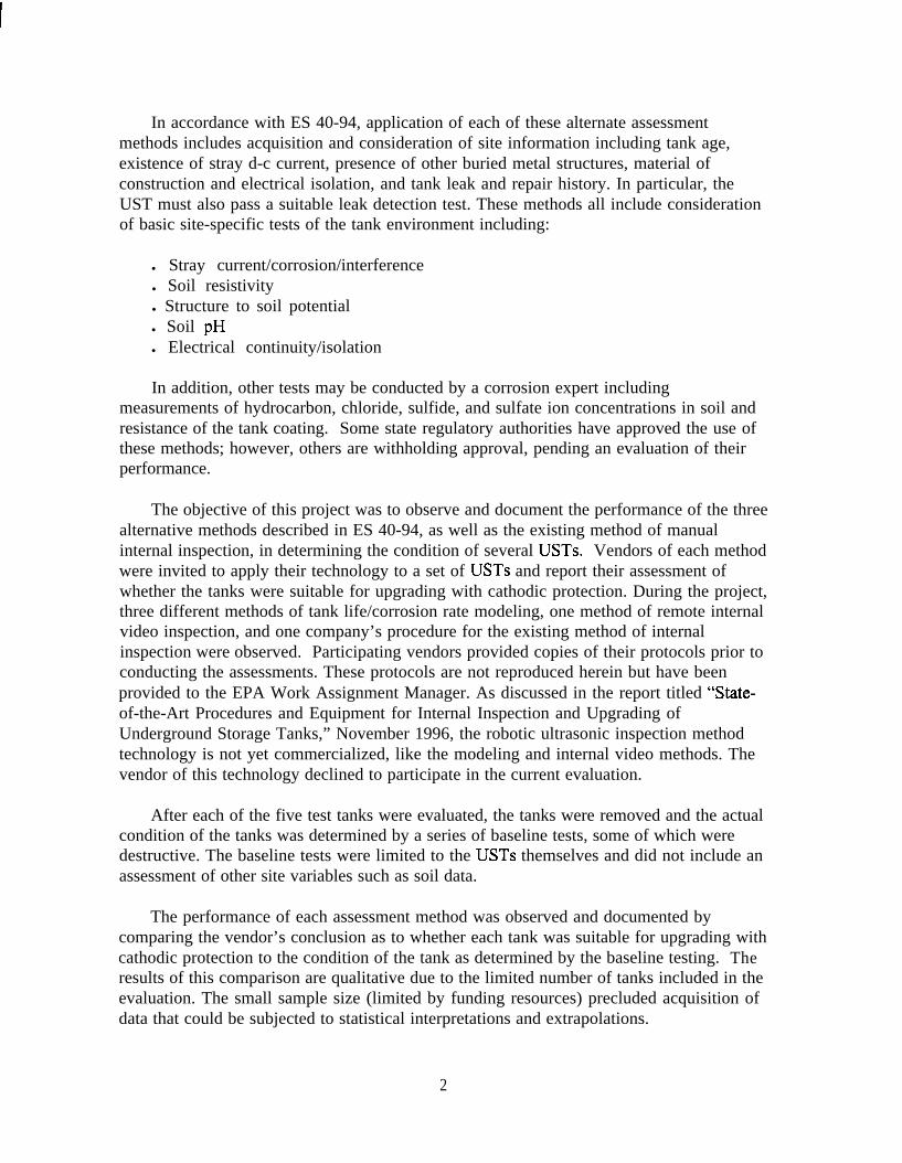
This study was conducted at the New Century Air Center, the former Olathe Naval AirStation, which is situated in New Century, Kansas, just north of Gardner. The U.S. ArmyCorps of Engineers was conducting a removal action involving a number of tanks at thissite. The specific tank gallery included in the study contained eight tanks which werearranged in two rows of four tanks each, separated by a concrete vault that contained pipingand valves. At the initiation of the project, two of the eight tanks were found to be filledwith water. Because this would not be typical, these USTs were excluded from the study.A schematic of the site is provided in Figure 1.
The history of the tanks was documented through discussions with facility personnel,the Corps of Engineers, and their contractor. It was determined that the tanks wereinstalled in 1943 or 1944. They had been used to store fuel for a small on-site power plantbuilt in 1943. The tanks were registered as having been installed in 1944. The tanks werenot cathodically protected. They were taken out of service 6 to 10 years ago, sometime inthe period of 1986 to 1990. At that time, the tanks contained No. 2 fuel oil or No. 2 diesel.Apparently the product was pumped out and the tanks left in place empty. Each of the sixtanks included in the study contained approximately 200 gallons of residual product withsome water phase in some of the tanks. The results of stick readings (presumably taken inAugust, 1995) were provided on the site drawing of that date. MRI confirmed themeasurements on the site drawings by sticking the tanks in July, 1996.
The tanks were used to fuel the boilers and diesel generators at a small power plant(Building 14). There were no submersible pumps or turbines present in the tanks. Fuelwas dispensed via a suction system, probably with a return line to each tank. The concretevault between the two rows of tanks was reported to contain piping and valves relating tothe fuel system.
A past employee contacted during the study indicated that early in the life of the tanks,they may have contained heavier product, e.g., No. 4 fuel for use in the power plant,however, more recently the product was No. 2. The tanks were found to be equipped withsteam heating coils along the bottom of each tank, implying that they were used or intendedto be used for heavy product such as No. 4 or No. 6 heating fuel.
No historical information regarding cleaning of the tanks was found. At the initiationof this project, they were cleaned by pumping out any residual sludges and liquids and thenpressure washed with a biosolvent. The study tanks included two tanks (Nos. 24 and 25)located on the south side of the vault and three tanks (Nos. 18, 19, and 20) which weresituated on the north side of the vault.
7

I
-5 AREA
/5 ----- -----
- -__-_-------- -A--_ TankMummy,‘< --=-.- c__________- --
_____-_____zI:I:l---- +- -
- - - - - -/ -‘------------------ - - - - --- - _--<-- _-- --a--
12VNTS.I
-----1j /I :Bi I
SECTION A-AI: * (0 mI I I I
SECTION B-B9: P 1. m
Figure 1. Diagram of the Tank Site
a

The initial information obtained indicated that the tanks were constructed of bare steel.Each tank had a circular access way 18 inches in diameter which was surrounded by aconcrete vault about 4 feet square. The portion of the tops of the tanks that was visiblearound the access ways appeared to be bare steel. However, when the tanks weresubsequently excavated, it was found that they had been coated with brushed-on coal tarand wrapped with kraft paper. This coating and wrap had slumped approximately one-thirdof the way down from the top of the tank and was not visible prior to excavation.

Section 3Tank Tightness Test Results
The ASTM ES 40-94 standard requires that a tank tightness test be conducted inconjunction with any of the alternative methods. The UST under-till test method waschosen for this study because the tanks were expected to have significant piping andconnections that might pose problems with an overfill test method, i.e., the overfill testmethod would also test the piping, which was not included in the scope of this study.
The tanks were tested using the water that had been stored in Tank Nos. 22 and 23.The water was pumped into each of the five test tanks in turn. The testing was conductedwith the tanks slightly more than 95% full. The test level ranged from 87 inches of waterto 90.5 inches of water.
A summary of the tank tightness test results is presented in Table 1. The completereport supplied by the tank tightness testing vendor is included in Appendix A.
Table 1. Summarv of Tank Tightness Test Results
I Tank number 1 Leak rate (gal/hr) 1 Conclusion I
18 0.665 Not Tight
19 0.016 Tank is Tiaht
20 0.344 Not Tight
24 0.074 Not Tight
25 0.103 Not Tiaht
During the tightness testing it had been assumed that any piping connections to thetanks entered through the top of the tank, which is usually the case. However, uponexcavation, it was discovered that some piping connections entered through the end cap ofeach tank. One end cap of each tank was found to have connections with two 1.5-inchpipes for the steam loop near the bottom of the tank. In addition, each tank had a 3 inchsuction pipe that entered in the center of the end cap and extended to near the bottom of thetank. Any leaks in this piping would affect the tank tightness test results. Additionally,these pipes might have had the effect of making all the tanks electrically connected throughthe piping. The four tanks on each side of the vault also had a common 4-inch fill pipe thatentered through the top of the tank at the end away from the concrete vault, which mighthave constituted an electrical connection between the four tanks on each side of the vault.
The tank tightness test results presented in Table 1 are not entirely consistent with thefindings of the subsequent baseline tests. For example, Tank No. 19 tested tight, althoughit was later found to have several perforations. A possible explanation is that the tankswere installed in very tight, moist, and highly plastic clay. This clay may have prevented
10

any significant loss of water during the test, allowing the conclusion that Tank No. 19 wastight. Further, the holes in Tank No. 19 and the other tanks were tilled with corrosionproduct when the tightness testing was being done. It is likely that this corrosion product,together with the clay backfill, reduced the leak rates from what would be expected withholes after the corrosion product was removed.
In addition, Tank No. 25 was judged to be leaking at a slow rate (0.103 gal/hi-), whileupon examination in the baseline tests it was found to have no perforations. Uponexamination, it was found that the 3-inch pipe in the center of the tank had been installedwith a brass fitting. Such a fitting would be likely to contribute to preferential corrosion ofthe pipe just outside the tank, and, indeed, some corrosion holes were found in some ofthose pipes. Thus, the leak rate indicated for Tank No. 25 by the tightness test might havebeen due to leaks in the 3 inch pipe rather than in the tank body.
11

Section 4Technology Test Results
Five vendors assessed the five test tanks at the study site. Three vendors used themodeling method of ASTM ES 40-94, one vendor used an internal video camera coupledwith a site inspection also per ASTM ES 40-94, and one vendor conducted internal (humanentry) inspections of the 5 tanks according to NLPA 63 1. The following subsectionsdescribe each vendor’s testing and results. Each method was observed and compared to theapplicable standard and to the vendor’s standard operating procedure. Deviations from thestandard, some of which were necessitated by the characteristics of the site, are noted inthis report. Appendix B contains the vendor reports.
4.1 Modeling Method
4.1 .I International Lubrication and Fuel Consultants, Inc. (ILFC)
ILFC conducted its assessment of the site and tanks over a six-hour period on July 18,1996, according to the corrosion modeling approach/procedures outlined in ASTM ES 40-94. A few adjustments had to be made based on site-specific conditions. About five fewerborings were taken than usual because the concrete vault and steps at the site preventedborings in these areas. ILFC took samples of product in two of the tanks as an addition totheir usual procedure.
The detailed test results are presented in the ILFC report in Appendix B. Structure-to-soil potential measurements were made in each boring. A stray current test was done. Soilresistivity was measured by the Wenner 4-point method, with spacings of 5, 10, 15, and20 feet, which is a slightly different spacing than suggested in ASTM ES 40-94. Soilsamples were taken to a laboratory and analyzed for several parameters, includinghydrocarbons.
ILFC concluded that on the basis of their field investigation and laboratory analyses,these tanks did not meet their TEP (Total Environmental Profile) criteria, nor did the tanksmeet the ASTM ES 40-94 criteria for upgrading by the addition of cathodic protection.After receiving the results of the tank tightness tests, ILFC did not change their conclusion.They reported that the tanks were electrically continuous and therefore represented oneunit, so the conclusion of not being upgradable applied to the site rather than to theindividual tanks.
12

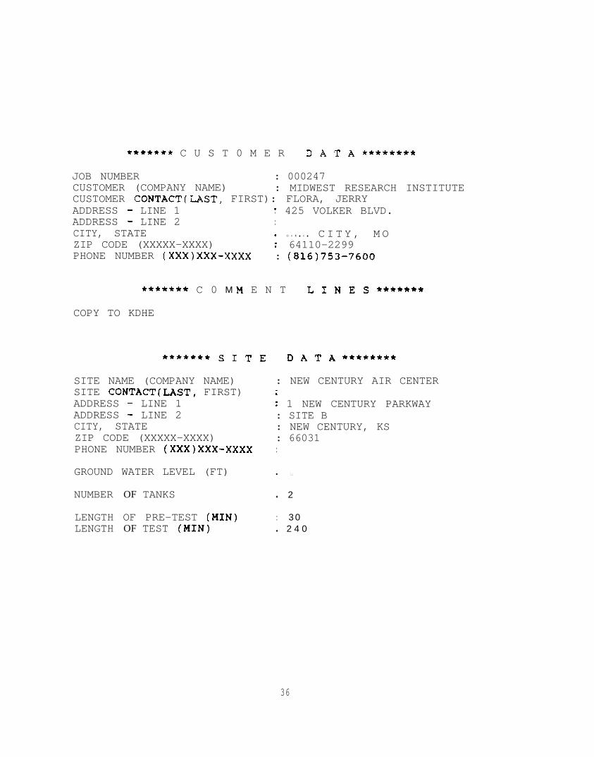
4.1.2 Corrpro Companies Incorporated/Warren Rogers Associates(WRKRP)
This method is based on a mean time to corrosion failure model. The field testing wasconducted by Corrpro and the report provided by Warren Rogers Associates. Testing in thefield was done over an 8-hour period on July 23, 1996. The testing would have beenfinished about 3:00, but the field crew encountered difficulty in finishing the last soilboring, hitting obstructions before they reached the depth of the bottom of the tank.Repositioning and drilling additional holes delayed the completion of the field work about2 hours.
As with the model used by ILFC, this method considers the site as a unit rather thanindividual tanks; i.e., results and conclusions are reported on a site basis-not forindividual tanks. Initially WR/CPR considered the test site as a single site, but later,decided that the separation by the concrete vault qualified it as two separate sites. Thus,WRKRP provided a result for the north side of the vault (Tanks 18, 19, and 20) and aseparate result for the south side of the vault (Tanks 24 and 25).
WRKRP followed the standard procedures required by ASTM ES 40-94. Only onelocation for the stray current test was required, because WRKRP determined that the tankswere all electrically connected. The field crew requested access through the access ways asper their standard procedure, which is to assess the tank interior through all availableopenings. After consultation with EPA, they were required to use the fill pipe for access,since many tanks do not have access ways, i.e., representative conditions were maintained.WRKRP also requested access to building 14 adjacent to the site for additional electricaltests. As MRI did not have access to that building, that access could not be provided.
The WRKRP report concluded that neither site was suitable for upgrading withcathodic protection. It stated that this result held regardless of the tank test results. Thestated reason was a high probability of corrosion failure for both sites. The estimated meantime to corrosion failure was 11.8 years for the north site, compared to a tank age of52 years. The estimated mean time to corrosion failure was 13 years for the south site,compared to an actual tank age of 52 years. A copy of the complete WRKRP report ispresented in Appendix B.
4.1.3 Southern Cathodic Protection (SCP)
SCP conducted the field work at the site over about a six-hour period on August 14,1996. Their method is based on a mean time to corrosion failure model and a probability ofcorrosion failure. They followed the procedures in the ASTM ES 40-94 standard and noteda few anomalies with the site. They noted an adjacent gas line that was cathodicallyprotected with an impressed current system and requested access to the rectifier to turn thesystem off to test for possible effects on the tanks. As MRI did not have access to therectifier box and was not able to obtain such access, that request could not be honored.SCP also noted that the field survey would normally be done only after receiving the resultsfrom the tank tightness test reports. SCP also noted, prior to the tests, that the model wouldnot predict a mean time to corrosion failure that exceeded the age of the tank (52 years).
13

Based on their experience with the model they knew it would not accept the site forupgrading with cathodic protection. During field testing, a soil box was used for soilresistivity rather than the Wenner 4-pin method.
SCP estimated that the mean time to corrosion failure for these tanks ranged from2 1.9 years to 23.4 years. Since the estimated time to failure is substantially less than theage of the tanks, SCP concluded that internal inspections are required in order to determinethe suitability of the tanks for upgrading with cathodic protection. That is, each tank wasdetermined to be unsuitable for upgrading with cathodic protection based on modeling, andan internal inspection was recommended. A copy of their report is presented inAppendix B.
4.2 Remote Video Camera Methods
4.2.1 Tanknology (TKNL) Internal Video
Tanknology assessed the five test tanks over a ten-hour period on July 29 and 30,1996. They followed their standard operating protocol, which complies with the ASTM ES40-94. Prior to inserting the camera, each tank was purged with CO, to inert the tank byreducing the tank’s oxygen content to less than 5%. Several structure to soil potentialreadings were taken, but no soil borings were taken. They also sought access to therectifier providing impressed current cathodic protection to the adjacent gas line in order totest for stray currents (with the rectifier turned off), but the access could not be provided.
Tanknology noted the presence of the steam pipes in the bottom of the tanks throughtheir video. They also noted the existence of the 3-inch suction pipe that entered the tank atthe middle of one end and then went into the vault. Although the tanks had been pressurewashed with a biosolvent, Tanknology noted that the tanks were still dirty, with heavybuildup in the bottoms. This may indicate a limitation on the use of the video, in that ifpressure washing the tanks from the outside does not provide a clean enough tank for theuse of the video, its application may be limited. The fact that these tanks may have hadheavy product in them for many years without cleaning may have resulted in the buildup ofresidue that limited the use of the video camera.
The conclusion of the visual inspection was that a light film has developed over thesurface of the tanks. Heavy trash encapsulation was prominent throughout the tanks, whichnecessitated an additional investigation, since surface areas were covered and not visiblefor viewing. The ullage area was covered with excessive rust and tubercle formation,requiring further investigation following proper cleaning. The sludge remaining along thebaffle plates and bracings for the heating coils also requires further investigation. Theoverall conclusion was that these tanks cannot be upgraded with cathodic protection untilfurther investigation and suitable repairs are made. The video tape review indicatedpossible penetration of Tank No. 19, possible pinholes on the side of Tank 18, a smallpinhole ingress on Tank No. 20, several suspect areas on Tank No. 25, and some suspectareas on Tank No. 24. All five tanks had some suspect areas, with three tanks havingsuspected perforations. A copy of the complete report is in Appendix B.
14

4.3 Internal Inspection Method
4.3.1 Armor Shield Internal Inspection
Armor Shield (AS) conducted internal inspections of the five subject tanks from July3 1 through August 7 using NLPA 63 1 as a guide. AS used a variety of internal inspectiontechniques for this work. A visual inspection was performed on each tank. AS stated thatin their opinion the state of the art for internal inspection was magnetic flux flaw detectionfollowing the visual inspection, with flaws indicated by the magnetic flux scan confirmedby ultrasonic inspection. This technique was new to the United States and differed fi-omthe standard method of an ultrasonic survey following visual inspection. After considerablediscussion, AS agreed to perform a variety of internal inspection techniques, which arenoted for each tank.
Each tank was first inerted, then entered by a technician equipped with personalprotective equipment and supplied breathing air. Although the tanks were equipped withaccess ways, the diameters of the access ways were too small for safe entry; consequently,openings were cut to enlarge the access way for each tank. The steam heating pipes wereremoved from the tanks, pipe ends were capped, and sludge was removed from the tanksand drummed for disposal. Each tank was then abrasively blasted to remove any scale,rust, or corrosion product from the tank walls prior to inspection.
The internal inspection work took considerably longer than usual. Abrasive blasting ofthe tank’s interiors had to be repeated after two days of heavy rain. The use of a variety ofinspection techniques extended the test time further, particularly since additional supplieshad to be shipped in.
AS identified areas with presumed external pits or flaws using magnetic fluxscreening. These areas were marked on the inside of the tank along with an ultrasonicallymeasured wall thickness. During the subsequent baseline testing, these areas wereinvestigated to determine whether an external flaw could be confirmed. The mostextensive investigation was conducted on Tank No. 25, a total of 26 such suspect areaswere identified. For 20 of these areas a deep external pit was identified. One area had aline of very shallow pits on the outside that might have been the cause of the detection.Five of the areas had no discernible external pit or flaw. Three areas were marked in TankNo. 18, and all corresponded to identifiable external pits. One area was marked in TankNo. 19 that corresponded to an external pit. The internal inspection also noted perforationsin Tank No. 24, which probably contained corrosion product until the external abrasiveblast removed it from the perforation.
The internal inspections resulted in the conclusion that none of the five tanks wassuitable for upgrading with cathodic protection alone. Since each tank was evaluated usinga different internal inspection technique, a summary of the results are presented below, bytank:
15

Tank 18 The visual inspection discovered perforations in the tank shell, whichdisqualified the tank for upgrading. Inspection was concluded at that point.
Tank 19 A partial magnetic flux scan was conducted. The tank was disqualifiedbecause of the discovery of perforations during the visual inspection.
Tank 20 A partial magnetic flux scan was conducted. The tank was disqualifiedbecause of the discovery of perforations during the visual inspection.
Tank 24 An ultrasonic flaw detector was used to scan the tank along its length at l-foot intervals. The ultrasonic scan concluded that the tank was not suitable forupgrading with cathodic protection, due to pitting that exceeded 50% of the tank wallthickness. This tank was not disqualified as a result of the visual inspection.
Tank 25 A magnetic flux inspection was conducted after the visual inspection. Onmost of the tank, 100% of the tank surface was subjected to magnetic flux scanning,but for part of the tank, only 50% was covered. The goal was to see if the 50% scancould also detect external pitting. As a result of the magnetic flux inspection revealingpitting that exceeded 50% of the wall thickness, the tank was found to be unsuitablefor upgrading with cathodic protection. The tank was also found to be unsuitable forupgrading from the visual inspection, which identified internal pits that measured morethan 50% of the wall thickness.
Tank 25 was also subjected to a standard ultrasonic survey with point measurementstaken at the approximate center of each 3-ft by 3-ft grid constructed on the interiorsurface of the tank. This tank was also found unsuitable for upgrading with cathodicprotection as a result of the ultrasonic survey. AS reported that all ultrasonic readingsin the first 3 feet of the north end of the tank indicated a wall thickness of less than85% of the wall thickness (based on an assumed original wall thickness of 260 mills).The readings on the north end cap were also less than 85% of the assumed originalthickness of 280 mills.
16

Section 5Baseline Test Results
Upon completion of the vendor testing and assessment, the tanks were excavated. Thetanks were removed from the excavation and placed on plastic sheets immediately north ofthe excavation. In general the tanks were lifted by placing an I-beam into the hole in thetop of the tanks that had been cut during the internal inspection. The I-beam was then liftedby a track hoe. The tanks were moved to a field about a quarter mile away for furtherinspection (Figure 2). They were scraped and brushed to remove adhering soil. At thatpoint it was discovered that the tanks had been coated with a brushed on coal tar andwrapped with Kraft paper. This wrapping and coating had slumped down along the sidesof the tanks, leaving approximately the top third of the tank without any coating or with aminimal residue. In addition, the ends of the tanks that were closest to the vault were foundto have a very wet coating, presumably from product interacting with the coating.
Upon removal, the exterior of each tank was visually inspected. Much of the tanks’surfaces could not be inspected effectively because of the coating and paper wrap.However, perforations were found in three of the tanks during this visual inspection. Theseperforations were approximately 3/8 inch in diameter, which rendered these tanksunsuitable for upgrading with cathodic protection, in accordance with the criteria specifiedin the QAPP.
The baseline tests were continued until a disqualifying flaw was found or until thespecified tests were completed. If no disqualifying flaw was discovered the inspection wascompleted and detailed information about any pits, the wall thickness, and condition of thetank was documented. The findings of the baseline tests are presented tank by tank,indicating the point at which a disqualifying conclusion was reached. A summary of thebaseline testing conducted on each tank is presented in the following paragraphs.
5.1 Tank No. 18
Immediately after removal, adhering clay soil was scraped from the sides of the tank.The tank was visually inspected and a perforation found about midway down the east sideof the tank a few feet from its north end. A probe placed into the hole confirmed that itcompletely penetrated the wall (Figure 3). Selected areas around the perforation wereabrasively blasted to bare metal and a number of obvious external pits were observed.Ultrasonic measurements were made on one end cap and a sidewall to obtain wall thicknessdata. These thickness measurements averaged 0.250 inch at section G-l and 0.279 at theend cap.
17

Figure 2 The Test Tanks During Testing
Figure 3 Perforation in Tank 18
18

5.2 Tank No. 19
Several large perforations were observed on the east side of the tank 6 to 9 feet fromthe north end and slightly above the midline (Figure 4). The area around the perforationswas sandblasted and inspected. Wall thickness measurements indicated an average sidewall thickness of 0.256 inch in section G-l and 0.267 on the end cap.
5.3 Tank No. 20
Tank No. 20 was removed from the ground on September 10, 1996. Visual inspectionprior to abrasive blasting identified a perforation on the west side of the tank about 7 feetfrom the north end (Figure 5). The exterior surface near the perforation was abrasivelyblasted. Wall thickness measurement indicated a thickness of 0.257 inch in section G-land 0.287 at the end cap.
5.4 Tank No. 24
Because of physical restrictions at the site, it was necessary to punch a hole with atooth of the track hoe bucket in the north end cap to lift the tank. A large dent a few feetfrom the north end of the tank also resulted from the removal. Considerable overlappingpitting around the area of the access way was observed; however, no obvious perforationswere found. Tank No. 24 was cleaned and an internal grid was applied in preparation forfurther baseline testing. The exterior of the tank was abrasively blasted. Following theabrasive blast, a small external pit was found which penetrated the tank shell. Theperforation was about one-eighth of an inch in diameter (Figure 6). Ultrasonicmeasurement in section H- 1 indicated a wall thickness of 0.246 inch and 0.262 in the endcap.
5.5 Tank No. 25
Tank No. 25 was the first and most difficult tank to remove, due to the constrictedworking space and suction caused by wet clay. During removal a track hoe dented the tankalong the west side and a hole was punched in the south end of the tank for lifting (Figure7).
The post-removal visual inspection identified considerable overlapping pitting aroundthe area of the access way. The tank was abrasive blasted and a grid was applied to thetank exterior. After the external inspection was completed, a grid was applied to the tankinterior. Data from the external inspection are in Appendix C. The data from the externalinspection, internal inspection, and ultrasonic wall thickness measurements are presented
19

Figure 4 . Perforations in Tank 19
Figure 5 Perbration in Tank 20
3 0- .-

Figure 6 Perf’ot-ation in Tank 23

in Appendix C. All welds were found to be Type 1 continuous welds on both ends of thetank. The head joint welds were all of Type 18, continuous full fillet welds on the outsideof the tank.
The external inspection identified a number of corrosion pits that were 0.10 inch deepor greater. The depth measurements for the six deepest external pits are presented in Table2. The values reported are the average of triplicate measurements. The location of each pitis indicated by the reference grid. The location is specified by the grid letter around thetank and the location along the length, as well as the sub-grid within the grid. For example,B 1,4-5 is in section B, closest to the open end, on the boundary between sub-grids 4 and 5.There were two pits at section C7-3 that were difficult to measure, as they were along aweld seam, one on each side. Both are reported in Table 2. All of these pits exceeded 50percent of the nominal wall thickness of 0.250 inch. No perforations were found.
Table 2. Six DeepestExternal Pits on Tank 25
I Grid Location Pit depth I
C7, 3 Outside Weld 0.199
C7, 3 Inside Weld 0.192
The five deepest internal pits were measured in triplicate and the average depths arereported in Table 3. The deepest of these approached 50 percent of the wall thickness, butdid not reach it.
Table 3. Five Deepest Internal Pits on Tank 25
G r i d L o c a t i o n Pit depth
DlO, 9 0.097
D9, 8 0.071
ElO, 3 0.103
ElO, 5 0.065
El, 2 0.102
Ultrasonic wall thickness measurements were made from the interior of the tank. Twogrid sections, A8 and H5, gave initial measurements that were less than 85 percent of the
22

minimum required wall thickness. The measurements at the center points for grid locationsA8 and H5 were 0.207 and 0.183, respectively. These two grid areas were subdivided into9 sub-grid areas and additional ultrasonic measurements were taken in each sub-grid. Theaverage of the 9 readings was used to determine the wall thickness for that grid. Theaverage of all side wall thickness measurements was 0.249 inch for Tank 25. The averageof the wall thickness measurements on the end caps was 0.272 inch. The average wallthickness computed over both the end caps and the side walls was 0.252 inch. The thinnestmeasurement of the ultrasonic survey was 0.096 inch for a point located in grid area H5.However, when all the measurements in that grid were averaged, it was determined that theaverage thickness was 0.236 inch. None of the 3-e by 3-ft grids averaged less than 85percent of the required minimum wall thickness of 0.204 inch.
Ultrasonic wall thickness measurements were also made from the inside of Tank 25 atthe location of the deepest external pits. To determine the minimum thickness in theseareas triplicate measurements were made. The average wall thickness in the area of the pitsidentified in Table 2 is presented in Table 4. The minimum, single-point individualmeasurement for wall thickness was 0.072 inch.
Table 4. Ultrasonic Wall Thickness at the Six DeepestExternal Pits on Tank 25
Id
Location Remaining wall thickness
Bl, 4-5 0.085
B6, 7 0.099
I BlO, 5 I 0.091
c2, 3 0.097
C7, 3 Outside Weld 0.084
I C7. 3 Inside Weld I 0.089
23

Section 6Results, Conclusions, and Recommendations
6.1 Results
As specified in the QAPP, three criteria must be met for a tank to be consideredsuitable for upgrading with cathodic protection.
Criteria 1. The tank must be free of corrosion holes. Any perforation will disqualify thattank.
Criteria 2. There must be not be pits deeper than 0.5 times the required minimum wallthickness and the average wall thickness in each 3 ft by 3 fi area must be atleast 85 percent of the required minimum wall thickness. A tank is unsuitableif either of these conditions is not met. (The required minimum wallthickness varies with the size of the tank, but is generally 0.240 inch.)
Criteria 3. The tank must be free of corrosion holes and cracks or separations in the tankwelds.
A summary of the baseline test results for the five tanks included in the study ispresented in Table 5. Each tank has been classified as either suitable or unsuitable forupgrading according to each of the three criteria specified above. In addition, themaximum pit depth, the minimum wall thickness, and the average wall thickness isreported for each tank.
Table 5. Summary of Baseline Test Findings
Average wallThickness
0.250* 0.0 No No No No
0.256a 0.0 No No No No
0.257a I 0.0 I No NoI 1 No~~~ I No
0.246a
0.252
0.0
0.207b
No No
Yes No
No No
Yes No
Ultrasonic measurements were abbreviated, since a perforation was found.b Minimum ultrasonic survey reading based on grid location averages. Minimum
wall thickness at a deep pit was 0.072 inch.
24

A summary of the results obtained by each technology evaluated is presented in Table6. The baseline test results are also included. Two of the modeling methods evaluated thesite as a whole, rather than individual tanks; WRKRP considered the study as two separatesites, while ILFC considered the site as a single site.
Conclusion Based onBaseline Test
25 1 No 1 No No No No No
a A “No” conclusion indicates that the tank is not suitable for upgrading by cathodic protection.
Notes:
1.
2.
3.
4.
5.
ILFC (International Lubrication and Fuel Consultants) concluded that all tanks were electricallycontinuous and evaluated the five tanks as a single site.
WR/CRP (Warren Rogers/Corrpro) concluded that neither excavation (north or south of thevault) is suitable for upgrading with cathodic protection and the site does not qualify. Theynoted that their results are on a site specific basis rather than on a tank specific basis.
SCP (Southern Cathodic Protection) concluded that none of the tanks meets the criterion forupgrading because each tank’s estimated mean time to corrosion failure is less than the age ofthe tank.
TKNL (Tanknology) concluded that further investigation and possibly repairs were necessarybefore any of the tanks could be upgraded by adding cathodic protection. Video log indicatespossible penetration on Tank #19, possible pinholes in Tank ##20, and pinhole ingress on Tank#18, with suspect areas noted on Tank ##24 and Tank #25.
AS (Armor Shield) reported on the basis of an internal inspection that Tanks 18, 19, and 20were not suitable because of perforations through the tank walls. Tanks 24 and 25 were notsuitable because of pits that were more than 50 percent of the wall thickness (i.e., greater than0.12 inch).
25

6.2 Conclusions and Recommendations
Application of each of the three technologies resulted in the determination that none ofthe tanks were suitable for upgrading with cathodic protection. The same conclusion wasreached as a result of the baseline testing. Therefore, in this very limited demonstration/assessment, each of the alternate technologies was successful in assessing whether the fivetest tanks were suitable for upgrading with cathodic protection. Because this studyinvolved a very small number of tanks at a single site, extrapolation of these results beyondthis project cannot be made.
This study demonstrated that all of the assessment techniques were applied accordingto the applicable standard and correctly identified the subject site(s) and tanks as notsuitable for upgrading with cathodic protection. The combination of limited funding andthe difficulty encountered in this study with finding sites with representative tanks limitedthe information available from the tests. Most of the candidate sites identified during thestudy contained old tanks suspected of being in poor condition. The age of the tanks (52years) at the study site made the evaluations and decisions regarding upgrading suitabilityvery straightforward for the experts applying the technologies. The study was far too smallto provide statistically valid conclusions about the methods’ performance. Accordingly,further study is needed to evaluate the performance of the methods.
Based on the above conclusions, further study is recommended to significantly expand thescope of work of this project. The expanded study should incorporate the followingcomponents to allow a statistically valid evaluation of the alternate technologies fordetermining the suitability of tanks for upgrading:
. Sites in five geographic regions of the United States
. 100 total (95 additional tanks) tanks, about 20 tanks per region
. Representative sites where tanks are actually being considered for upgrading
. Inclusion of the robotic ultrasonic technology, when it is commercially available.
26

Appendix A
Tank Tightness Test Reports
27

INVOICE IKKOOO248RANGER PETROLEUM
PO BOX 1283BLL'E SPRINGS, MO 64013
(816)625-7255
TANK STATUS EVALUATION REPORT-----------------------------
TEST DATE: 07/21/96
l **** aSl�+C)m DATA **tt* ***** SITE DATA l ****
MIDWEST RESEARCH INSTITUTE425 VOLKER BLVD
KANSAS CITY, MO64110-2299
NEWCENTURY AIRCENTER1 NEW CENTURY PARKWAYSITE BNEW CENTURY, KS66031
CONTACT: FLORA, JERRY CONTACT:PHONE #: (816)753-7600 PHONE #:
***** COMMENT LINES *****
COPY TO KDHE
CURRENT EPA STANDARDS DICTATETHAT FOR UNDERGROUND FUEL TANKS, THE MAxIMUFf ALLOWABLE LEAK/GAIN RATE
OVER THE PERIOD OF ONE HOUR IS .lO GALLONS.
TANK 118: WATER TYPE: STEEL RATE: .665479 G.P.H. LOSS
TANK IS NOT TIGHT.------------------
TANK 119: WATER TYPE: STEEL RATE: . 016356 G.P.H. LOSS
TANK IS TIGHT.
3PERATOR: <L &&L SIGNATURE: DATE:---------------_-___ , L-- ------------ 2~1_L!L-
28

*****+* T A N K D A T A ********
TANK NO. TANK NO. TANK NO. TANK NO.18 19 3 4
TANK DIAMETER (IN) 96 96LENGTH (FT) 31.67 31.67VOLUME (GAL) 11907 11907TYPE ST ST
FUEL LEVEL (IN)
FUEL TYPE
dVOL/dy (GAL/IN)
CALIBRATION ROD
87
WATER
9 2 . 0 6
DISTANCE
10.656326.953141.937556.937574.9375
. 0000
. 0000
. 0000
88
WATER
87.29
10.656326.953141.937556.937574.9375
. 0000
. 0000
. 0000
29

******* C U S T 0 M E R D A T A ******f+
JOB NUMBER : 000248CUSTOMER (COMPANY NAME) : MIDWEST RESEARCH INSTITUTECUSTOMER CONTACT(LAST, FIRST): FLORA, JERRYADDRESS - LINE 1 : 425 VOLXER BLVDADDRESS - LINE 2 ..CITY, STATEZIP CODE (XXXXX-XXXX)
: KANSAS CITY, MO: 64110-2299
PHONE NUMBER (XxX)XxX-XXXX : (816)753-7600
******* C 0 M M E N T L 1 N E S ***+rt**
COPY TO KDHE
*++*+++ S 1 T E
SITE NAME (COMPANY NAME)SITE CONTACT(LAST, FIRST)ADDRESS - LINE 1ADDRESS - LINE 2CITY, STATEZIP CODE (XxXxX-XXXX)PHONE NUMBER (XxX)XxX-XXXX
GROUND WATER LEVEL (FT)
NUMBER OF TANKS
LENGTH OF PRE-TEST (MIN)LENGTH OF TEST (MIN)
D A T A *++*+**+
: NEW CENTURY AIR CENTER.
i 1NEWCENTURY PARKWAY: SITE B: NEW CENTURY, KS: 66031..
: 0
:2
: 30: 240
30

INVOICE #KKOOO249 TEST DATE: 07/22/96RANGER PETROLEUM
PO BOX 1283BLUE SPRINGS, MO 64013
(816)625-7255
TANK STATUS EVALUATION REPORT-----------------------------
***** CUSTOMER DATA l **** ***** SITE DATA l ****
MIDWEST RESEARCH INSTITUTE425 VOLKER BLVD
KANSAS CITY, HO64110-2299
NEW CENTURY AIR CENTER1NEWCENTURYPARKWhYSITE BNEW CENTURY, KS66031
CONTACT : FLOTU, JERRY CONTACT:PHONE X: (816)753-7600 PHONE R:
l **** COWMENT LINES l ****
COPY TO XDHE
CURRENT EPA STANDARDS DICTATETHAT FOR UNDERGROUND FUEL TANKS, THE MiUIMUM ALLOWABLE LEM/GAIN RATE
OVER THE PERIOD OF ONE HOUR IS .lO GALLONS.
TANK 120: WATER TYPE: STEEL RATE: . 343578 G.P.H. LOSS
TANK IS NOT TIGHT.--___-------------
TANK I21: WATER TYPE: STEEL RATE: . 110466 G.P.H. LOSS
TANK IS NOT TIGHT.------------------
OPERATOR: hL LL SIGNATURE: g d!? DATE:-c---------------- 7,2.&-----------------___ --------
31

******* T A N K D A T A ********
T A N K N O . TANK NO. TANK NO.20 21 3
TANK DIAMETER (IN) 96 96LENGTH (FT) 31.67 31.67VOLUME (GAL) 11907 11907TYPE S" ST
FUEL LEVEL (IN) 88 90.5
FUEL TYPE WATER WATER
dVCL/dy (GAL/IN) 87.29 73.40
CALIBRATION ROD DISTANCE
1 10.65632 26.95313 41.93754 56.93755 74.93756 . 00007 . 0000a * 0000
10.656326.953141.937556.937574.9375
* 0000. 0000. 0000
TANK NO.4
32

******* C U S T 0 M E R D A T A *+*f++++
JOB NUMBER : 000249CUSTOMER (COMPANY NAME) : MIDWEST RESEARCH INSTITUTECUSTOMER CONTACT(LAST, FIRST): FLORA, JERRYADDRESS - LINE 1 : 425 VOLKER BLVDADDRESS - LINE 2 ..CITY, STATE : KANSAS CITY, MOZIP CODE (XxXxX-XXXX) : 64110-2299PHONE NUMBER (XxX)XxX-XXXX : (816)753-7600
******* C 0 M M E N T L 1 N E S f**+***
COPY TO KDHE
rt+****+ S 1 T E D A T A ****++**
SITE NAME (COMPANY NAME) : NEW CENTURY AIR CENTERSITE CONTACT(LAST, FIRST) :ADDRESS - LINE 1 : 1NEW CENTURY PARKWAYADDRESS - LINE 2 l SITE BCITY, STATE ; NEW CENTURY, KSZIP CODE (XxXxX-XXXX) : 66031PHONE NUMBER (XxX)XxX-XXXX :
GROUND WATER LEVEL (FT) : 0
NUMBER OF TANKS :2
LENGTH OF PRE-TEST (MIN) : 30LENGTH OF TEST (MIN) : 240
33

I?TVOICE iyKKOOO247 TEST DATE: 07/19/96?.ANGER PETROLEUM
PO BOX 1283BLUE SPRINGS, MO 64013
(816)625-7255
TANK STATUS EVALUATION REPORT-----------------------------
l **** CUSTOMER DATA l **** **+** SITE DATA l ****
MIDWEST RESEARCH INSTITUTE425 VOLKER BLVD.
KANSAS CITY, HO64110-2299
NEW CENTURY AIR CENTER1 NEW CENTURY PARKWAYSITE BNEW CENTURY, KS66031
ZONTACT: FLORA, JERRY CONTACT:PHONE d: (816)753-7600 PHONE #:
l **** COMMENT LINES l ****
COPY TO KDHE
CURRENT EPA STANDARDS DICTATETHAT FOR UNDERGROUND FUEL TANKS, THE MAXIMUM ALLOWABLE LEAK/GAIN RATE
OVER THE PERIOD OF ONE HOUR IS .lO GALLONS.
CANK 124: WATER TYPE: STEEL RATE: . 073991 G.P.H. LOSS
TANK IS NOT TIGHT.------------------
TANK X25: WATER TYPE: STEEL RATE: . 102721 G.P.H. LOSS
TANK IS NOT TIGHT.------------------
TPERATOR: KL kLu SIGNATURE: DATE: .7,: f ,'$;-------------------_ ------------------- --------
34

******* T A N K D A T A ********
TANK NO. TANK NO. TANK NO.24 25 3
TANK DIAMETER (IN) 96 96LENGTH (FT)VOLUME (GAL)TYPE
FUEL LEVEL (IN)
FUEL TYPE
dVOL/dy (GAL/IN)
CALIBRATION ROD DISTANCE
31.67 31.6711907 11907
ST ST
89.5 89
WATER WATER
79.35 82.11
10.656326.953141.937556.937574.9375
. 0000
. 0000
. 0000
10.656326.953141.937556.937574.9375
0000: 0000. 0000
TANK Nc
35
******* C U S T 0 M E R D A T A +*+*+*+*
JOB NUMBER : 000247CUSTOMER (COMPANY NAME) : MIDWEST RESEARCH INSTITUTECUSTOMER CONTACT(LAST, FIRST): FLORA, JERRYADDRESS - LINE 1 * 425 VOLKER BLVD..ADDRESS - LINE 2 ..CITY, STATE l K A N S A S C I T Y , M OZIP CODE (XXXXX-XXXX) i 64110-2299PHONE NUMBER (XxX)XxX-XXXX : (816)753-7600
******* C 0 M M E N T L 1 N E S **+****
COPY TO KDHE
+++++** S 1 T E
SITE NAME (COMPANY NAME)SITE CONTACT(LAST, FIRST)ADDRESS - LINE 1ADDRESS - LINE 2CITY, STATEZIP CODE (XXXXX-XXXX)PHONE NUMBER (XxX)XxX-XXXX
GROUND WATER LEVEL (FT)
NUMBER OF TANKS
LENGTH OF PRE-TEST (MN)LENGTH OF TEST (MN)
D A T A *****t++
: NEW CENTURY AIR CENTER
I 1 NEW CENTURY PARKWAY: SITE B: NEW CENTURY, KS: 66031:
l 0.
l 2.
: 3 0l 2 4 0.
36

Appendix B
Technology Vendor Reports
37

lntcrnotionolbbricotton ondfuel Consultants
P.o.8ax 15212Rio Rancho, NM 87 174
(505) 892-1666 (800) 237-4532Fax (SOS) 892-9601
u FC. mC. TFP ANA1 Ym NO. 50-804DATE: August 1 J, 1996
FOR: Midwest Research Institute425 Volker Blvd.
Kansas City, MO 64110
SIT-E ID: New Century1 New Century Parkway
New Century, KS 6603 1
TEPH (Total Extractable Petroleum Hydrocarbons) concentrations are listed on the si:e map,Anallyses show the presence of petroleum hydrocarbons, classified as very aged diesel fuel, inmost of the soil sampies taken around these fuel systems.
Half-ceil measurements which were taken between these fuel systems and their surrounding soilindicate that there IS a slgruficanr amount of steel structure remairung In good condinon inregards to corrosion.
The Class IV CH (inorganic c!ays of high plasticiry. fat clays) soil has an average pH of 8(aikaiine). an average molsrure content of 18.5%. an average bactetia count of 50.000 spores/ml,average soil resrsuvity of I.100 ohm-cm. an average chloride content of 2 ppm and a sulfideconcentration of 497 ppm.
Based on the field investrgauon and laboratory analyses performed on this sne It appears thesefuel systems do not meet satisfactory TEP an&or ASTM ES 40-94 critena. ILFC, inc. stronglyrecommends investigatmg the source of contamination and providing us with the tank tightnesstesting history of this me. We till re-evaluate this site as soon as we receive this information. Lnthe interim if we can be of any further assistance or if more information regarding our fieldinvestigation and/or laboratory analyses is needed piease do not hesitate IO contact us at
R,@Wmiri,/Petroieum\Corroston Engmeer President
38

INIfiHNATIONAL LUBRICATION U l-UEL CONSULTANTS, INC. tt~o fiancho, New Mexico 81124 (8~) ?.j/ <!!I ~2
TEP SITE ANALYSIS: PLOT OF HAL~F-CELL READINGS AND t1YDROCARDON ANA\ YS- - -@ Top TEPH 21 ppm@ Mid TEPH ii ppm 8 Top TEPH 23 ppm
& Bottom TEPH 2U ppm @ Botlom TEPH 36 ppm-o 6, ,”
0 7 0 8 0 9 Q @4’ TEPH 309’ TEPH 49 ppm ppm
-0.516v -0.527~Q Bottom rEPff 44 ppm
@ Top TEPH 23 p@ Bottom TEPti 18
06
-0.502v
I-:
-0.513v
05@ Top TEPti 32 ppm@ Mid TEPH IO ppm
@ Deep TEPti ~20 p/aTVPH <MDL
@ Top TEPH 16 ppm@ Mid TEPH 16 ppm
@ Bottom TEPH 16ppmTVPH <MDL
04
-0.525v
r
IIIll
1-A AN K U2 (26jl2,lUM GAL
WATERDIESEL
@ Top TEPH I4 ppm@ Mid TEPH 5 ppm@ 12’ TEPti 40 ppm
TANK #4 (19j12,000 GAL
EMPTYDIESEL
l0
rANK 65 (20)12,000 GAL
EMPTYM2 FUEL O/L
ll
Top TEPH 3 #jptn
I -0.5oovI 010
TANK #6 (21) @ 4’ TEPH 92 ppm, FCI 4 ppm12.000 GA L @ 6’ TEPH U ppm
EMPTY @ 11’ rEPIf 3 ppnlDIESEL
-0.49fv
0 IO-BkTEPH 91 ppm; F/D 63ppm
6 @ p TEPH 143 ppm’ FID 194 ppm
Id TEPti 10 II meep TEPti 5 I pm
58Ov
0 2’ TEPH 1I .3 ppm-0.542~ iip 4’ TEPH 433 jirn;0 3 0 2 8 7’TEPH 17ppm
-0.627~ 8 13’ TEPH 23 ppm
& 0 TEPH 73ipm;TVI’H WDL
F/D 2 ppm
F/D 75ppm
DATE ON SITE: 7/1W96
DATE OF ANALYSIS: 7/24/96
CLIENT:Mdwesl Research losliMe
425 Voiker 6JvdK<r,nsas C~fy, MO 641 10
i RESIJI 1 S_-___-_--~.__~___-LEGEND
pprn t1YOttOCAHEWNS
ClNo I I( )I E NUMBER
!!Nf’ @! I HEAD!NGS
-
Nolo: Kepc~ led dS
1 EPt 1 PPhl1 WI I PP hf
ptl 8 0
Sod Heslslwlly 111 olwl cm
5 feel I 05610’ 1.15220’ 1,997
Mo~slure content 18 5%
Soil microbe counl
10,00om1
Chlonde Contenl 2 ppm
Sulfide Covalent 497 ppnt
Dnwlng No.MRI - TEP
New C8il1llfy Auporl
Drawn By: K u a&J w
Date: 7/22/96--.~~~-____-

BV
bA

lntsrnotionallubrication andfuel Consultants
ireatiry th
P.O. Box 15810RioRoncho,NM87174
(505) 892-1666 ( 8 0 0 ) 937-4534Fox (505) 892-9601
rnh.itnj.
November 5. 1996
Mr. Robert L. HoyeProject ManagerIT Corporation11499 Chester RoadCincinnati, OH 45246
REF: New Century Air Center EPA Contract No. 68-(22-0 108
Dear Mr. Hoye:
Thank you for the information sent to us on November 1, 1996. Due to the factthat the tanks at this site are electrically continous and therefore considered oneunit, we will not revise our original conclusion that the fuel systems at this site donot meet satisfactory TEP and/or ASTM ES JO-94 criteria.
S incereiy ,
Petroleum/Corrosion Engineer
cc: J. Flora
41

Warren Rogers Associates. Inc.
October 115, 1996
Mr. Bob HoyeIT Corporation11499 Chester RoadCincinnati, OH
Re: US EPA Research Project “Evaluation of Technologies for Upgrading UST Systems”;Contract 68-CZ-0108. WA 4-17, JTN 76439
Dear Mr. Hoye:
Please find attached the results of the MTCF7M analysis of the two UST excavations in KansasCity where representatives of Con-pro conducted field measurements and observations. Basedupon your recent telephone conversation with Warren regarding the site specific nature of theMTCFTM procedure, it is our understanding that a footnote regarding the site specific nature ofthe analysis is to be provided with Table l-l of the QAPP.
As you’ll note, cathodic protection upgrade is m considered a viable option for either site(excavation). In addition to the high probability of failure. the presence of a nearby cathodicallyprotected structure and the fact that the UST’s are likely resting on a concrete pad precludeconsideration of cathodic protection retrofit at either ofthese sites. Regardless of the results ofthe prior leak detection testing. the recommendation that these tanks not be considered forcathodic protection upgrade will stand.
/If you have any questions or comments, please call.
Executive Vice Pr&dent
747 Aquidneck Avenue Middletown. Rhode island 028-12 (401) 8364747 Fax (301) 847-8170
42

I-
___--w---7----q*;Cn’F..r(J -’ n-y7 - -
I----we s i c : ; I
-------------------------i
B-
i
ExcwatmnLlmlt
t
, c c : c-c -
:s II.--..
1 III
\F O R ‘UAT? UAlN E7E341RSEE,OR A’MN^, ~5
44
L-L------------______--i--r-+?
/”1072.33 I
50' /
Jr Ii
A
43

WRA M.T.C.F. ’ - Corrosion Failure Prepared by: Corrpro Companies, Inc.610 Brandywine Parkway, West Chester, PA
Prepared on October 15. 1996 forEPA TEST SITE
LocatIon ID EPAKSAEPAKSAROLAND PARK DR (BLDG 14)NEW CENTURY, KS
Operator ROBERT HILGER913-782-5338
PROBABILITIES AND TANK INFORMATION
Location Name Conditional Probabilityof Corrosion Fallure
Given Pitting Corrosion
Probabllity of Mean Time toLocalized Corrosion Corrosion Failure
Tank Age
EPAKSA
Present
0 999
PresentII saluraled
N/A
Future
0999
Present
N/A
Future
N/A
RECOMMENDATION
The percent probabilrty of corrosion failure precludes consideration of this srte for cathodic protection retrofit The exrstence of a nearby cathodicalty protected slructure mrhtates against prolonged lank lrfe Thissite does M meet ASTM ES-40 94 criteria for upgrading by cathodic protectron
I I I 1 I I I I I I I I
‘-ConflrmaUon: l=Seme as Company Infomutwn. Z=Memnf Ihm Company Informalton
Engineer. G E ALBRECHT

EPAKSB MTCF Report - Page 2SITE INFORMATION.- .._. _...._... -..
Artiio Fbrtrirnl PIa mm’ tktafuw in feet7 I N n.,-.BrP1 -*dm.-..a - rL9 I u 1. .-...- w--...-. . .,nt Nearby? Type of Syst _..., _._- ..__ . . .___.
Cathodically protected structures nearby?; Distance in feet’?
Utility vaull or conduit nearby?
Potable water well nearby7
Waterway. stream or lake nearby?
Line leak detectors installed?
“.~l~)ll \*nlUIIII~11 ml *nvr
Monii welh on SW
La& hbtcuy avalbbb on s1c?
Repair history availabls on sb?
Site plans availabk on site?
Installation specs available on site?
Piping material7 I s 1 Type of pump? I S1
LABORATORY INFORMATION
Moisture Content(% Dry Weight)
27 03% - 30 73%PH
72-05
Conductlvlty(micromhos)
230 - 568
Sulphldes(Ppm)
oooo-oooo
Chlorides(Ppm)
I- 6
TYPE OFBACKFILL’
ON SI
WRA M. I’. c. I;. L - Corrosion Failure Prepared by: Corrpro Companies, Inc.610 Brarrdywirre Parkway, West Chester, PA
Prepared on October 15. 1996 forEPA TEST SITE
LocatIon ID EPAKSB Ooerator ROBERT HILGEREPAKSAROLAND PARK DR (BLDG 14)NEW CENTURY, KS
913-762-5336
PROBABILITIES AND TANK INFORMATION
Location Name Conditional Probabilityof Corrosion Failure
Given Pitting Corrosion
Probabllity ofLocalized Corrosion
Mean Time toCorrosion Failure
II I 1I I I IPresent Present
1 rmurmedFuture Present Future
EPAKSA 0.998 N/A 0 999 N/A N/A 130
LocationI
GallonsI
Dlmenslons Bottom -Depth Internal Internal lnfonnatlon Isolated(Inches) Water Corrosion Confirmation’ VW
Year Tank
I I
ProductInstalled Type
lank Age
52 00
RECOMMENDATION
g The present probability of corrosion failure precludes consideration of this site for cathodic protection retrofit The existence of nearby cathodiilly protected structures miktates against prolonged lank kfe Thissite does noJ meet ASTM ES 40-94 critena for upgrading by cathodic protection retrofit
‘Contlrmatlon: l=Sam8 as Ccnm&wy Inlormal~~~ Z=D~Rerenl than Company Inl@lon
1213 1 I44 Steel DSL
1213 1144 Steel DSL
12731144 Steel DSL
1213 1 I44 Steel DNV
I I
I122 [ 025 Smooth I N
123 075 Smooth 1 N
121 I 0.00 Rough 1 N
121 1 000 1 Smooth 1 I I N
I I I II I I I
I 1I I I I
Engineer G E ALBRECHT

EPAKSA MTCF Repoti - Page 2SITE INFORMATION
Cathodically protected structures nearby?; Distance in feet?
Utlli vault or conduit nearby?
Potable water well nearby?
Waterway, stream or lake nearby?
Line leak detectors installed7
Pioino material?
Y-25 Monllorklg wens on sne? NLed hbtory avallbb on Sk? N
N Repair history avritabb on rite? NN Site plans avaibhb on site? Y
N lnstalbtion specs availabb on stte? NS Tvw of ounm? S
LABORATORY INFORMATION
Moisture Content(% Dry Weight)
20 05% - 41 11%
Uafllr ,..,.I3 I. to ASW III, I6 IOON SITE SOIL SAMPLE ANALYSIS
Conductivity Sulphldes(mlcromhos) (Ppn)
121 -458 oooo-oooo
rnodxl* I..ld ,, (0 Ami4 Irn ! alwlbdm ,n,.* . . 10 WI 371 !
SAMPLE DEPTH SQUEEZE GROUND TYPE OF SAMPLE DEPTH SGUEEZE GROUND TYPE OFLOCATION (FT) MOISTURE WATER BACKFILL’ LOCATtON v-l MOISTURE WATER BACKFILL’(HOLE I ) TEST LEVEL (HOLE # ) TEST LEVEL
(YES/NO) (FEET) (YES/NO) (FEE-Q
1 TOP 2 N 3 3 TOPMIDDLE 6 N 3 MIDDLEBOTTOM 10 Y 7 3 BOlTOM
2 TOP 2 N 3 4 TOPMIDDLE 6 Y 6 3 MIDDLEBOTTOM 10 Y 3 BOTTOM
ON SITE HOLE PROFILE
II HOLE #I . POTENTIAL AND i- HOLE #Z . POTENTIAL AND II HOLE I3 - POTENTIAL AND II HOLE W - POTENTIAL ANDRESISTIVITY PROFILE II RESISTIVITY PROFILE
DEPTH POTENTIAL RESISTANCE DEPTH POTENTIAL RESISTANCEFT) VW (OHM-CM) FT) (NW (OHM-CM)
2 -520 00 630 00 2 -525 00 924 00
4 -527 00 714 00 4 -525 00 924 cm1 I I, 1 1
6 1 -530 00 1 840 00 11 6 -52700 1 924 00
8 -543 00 802 00 a -52400 1 117600
10 I -54900 I 000 II 10 I -523 00 000
RESISTMTY PROFILE
DEPTH POTENTIAL RESISTANCEV=T) WV) (OHM-CM)
RESISTIVITY PROFILE
m

EPA - 01~4 TIIt?, KS MTCF Report - Page 3
i
WiAY C U R R E N T A N A L Y S I S
# O F
EADNGS M O S T M O S T
JAKEN POSWIVE A V E R A G E NEGATIVk
2 6 3
2 6 2
261
260
2 6 0
2 5 9
2 5 9
2 5 7
2 5 7
2 5 6
2 5 6
2 5 5
2 5 5
2 5 6
2 5 4
2 5 4
2 5 4
2 5 4
254
251
2 5 3
2 5 2
2 5 0
2 5 0
2 4 9
2 4 9
2 4 9
2 4 6
2 4 0
2 4 7
531
5 3 2
5 3 3
534
5 3 5
5 3 5
5 3 6
5 3 6
.- 536
5 3 6
- 5 3 6
- 5 3 6
5 3 6
- 5 3 6
-~ 537
- 5 3 7
- 5 3 7
5 3 7
5 3 6
5 3 6
5 3 6
5 3 8
5 3 0
-536
530
5 3 7
--537
- 537
-- 536
5 3 6
5 3 0
- 531
5 3 2
5 3 3
5 3 5
5 3 4
5 3 5
- 5 3 6
- 5 3 6
- 5 3 6
-- 536
- 5 3 6
-- 536
- 5 3 6
- 5 3 6
- 537
- 5 3 7
- 5 3 7
- 5 3 6
- 537
5 3 7
5 3 6
-530
- 5 3 6
- 5 3 7
- 5 3 7
5 3 7
- 5 3 0
- 5 3 6
-536
- 532
5 3 3
5 3 4
5 3 5
- 535
- 536
5 3 6
- 537
- 5 3 7
-530
- 5 3 7
-530
- 5 3 6
- 537
- 5 3 7
- 5 3 7
-530
-530
- 5 3 0
-530
-- 539
- 5 3 6
- 5 3 0
-530
-530
-530
- 5 3 0
- 5 3 7
-!I30
- 5 3 6
FlRsT- 530
- 5 3 1
-. 533
5 3 4
- 5 3 5
- 535
~- 535
- 536
- 537
- 536
- 5 3 6
- 5 3 6
- 5 3 6
- 5 3 6
- 5 3 7
- 5 3 7
- 5 3 7
- 5 3 7
- 5 3 0
- 5 3 0
- 5 3 7
- 5 3 6
- 5 3 0
-530
- 5 3 0
- 5 3 7
-537
- 5 3 7
-530
- 5 3 0
GREATkA
T H A N
i 50-
0
0
0
0
0
0
0
0
0
0
0
0
0
0
0
0
0
0
0
0
0
0
0
0
0
0
0
0
0
0
tsoT O
+41
0
0
0
0
0
0
0
0
0
0
0
0
0
0
0
0
0
0
0
0
0
0
0
0
0
0
0
0
0
0
t40 t30
T O T O
fl )21
0 0
0 0
0 0
0 0
0 0
0 0
0 0
0 0
0 0
0 0
0 0
0 0
0 0
0 0
0 0
0 0
0 0
0 0
0 0
0 0
0 0
0 0
0 0
0 0
0 0
0 0
0 0
0 0
0 0
0 0
t 20
T O
111-
0
0
0
0
0
0
0
0
0
0
0
0
0
0
0
0
0
0
0
0
0
0
0
0
0
0
0
0
0
0
t 10 - 10
T O T O
0 ;1
2 6 2 1
2 5 6 6
2 5 0 3
2 5 6 4
2 5 3 7
2 2 6 3 3
2 5 6 3
176 81
6 251
2 2 7 31
9 5 161
3 0 2 2 5
197 60
2 4 4 12
161 9 3
2 2 7 2 7
2 5 2 2 9
2 5 4 0
2 5 4 0
2 6 2 2 5
251 2
2 1 0 4 2
50 194
1 2 4 9
7 5 174
3 2 2 1 7
136 1 1 3
1 2 4 7
4 3 2 0 5
6 241
-1-
-it
T O
22
0
0
0
0
0
0
0
0
0
0
0
0
0
0
0
0
0
0
0
0
0
0
0
0
0
0
0
0
0
0
- 21
T O
- 3 0-
0
0
0
0
0
0
0
0
0
0
0
0
0
0
0
0
0
0
0
0
0
0
0
0
0
0
0
0
0
0
-~ 31
T O
-40
0
0
0
0
0
0
0
0
0
0
0
0
0
0
0
0
0
0
0
0
0
0
0
0
0
0
0
0
0
0
-41
T O
5 0-
0
0
0
0
0
0
0
0
0
0
0
0
0
0
0
0
0
0
0
0
0
0
0
0
0
0
0
0
0
0
L E S S
T H A N
-50
0
0
0
0
0
0
0
0
0
0
0
0
0
0
0
0
0
0
0
0
0
0
0
0
0
0
0
0
0
0

EPA - OkLATHE KS MTCF Report - Page 3
STRAY CURRENT ANALYSIS
II
-. -___- -. I_--__. __-~ -___ ~~__ _ _ _ _ _
---__.. #OF .--.- ~ --.~~__~
GREATER +50 t40 +30 t20 t10 - 1 0 - 1 1 - 2 1 - 3 1 - 4 1
READINGS MOST MOST THAN T O T O T O T O T O T O T O T O T O T O
TAKEN POSITIVE AVERAGE NEGATIVE B +50 t 4 1 t31- - a+11 QA -20 -30
246 - 535 -- 535 -536 - 536 0 0 0 0 0 1 245 0 0
246 - 535 -534 -535 - 535 0 0 0 0 0 9 237 0 0
246 -534 -534 -534 - 534 0 a a 0 0 33 213 a 0
246 - 534 -534 - 534 - 5 3 4 0 a 0 0 0 64 162 0 0
247 - 534 -634 -535 - 5 3 4 0 0 0 0 0 239 6 0 0
246 - 535 - 535 -535 - 535 0 a 0 0 0 245 1 0 0
246 - 536 - 535 - 536 - 535 0 0 0 0 0 240 6 0 0
245 - 537 -536 - 539 - 5 3 6 0 0 0 0 0 242 3 0 0
s .-196 - 537 - 537 -536 - 537 0 0 0 0 0 172 24 0 0--~~ .___~.. -___-__
A!2 -500 0
0 0
0 0
a 0
0 0
0 a
0 0
0 0
0 0
LESS
THAN
-50
0
0
0
0
a
a
a
a
a

Refirtnce: StausncaI COITOTOT~ ProbaSilic AnaIgisL’ndergound Storage Tank SystemSew Cemay Air Center, New Cenaa)., Kmsus
Dear -Llr. Flora
Enclosed please tind 2 copy of the corrosion evaluatian repart which f&la to met the ASTM ES 40-94standaf~whichistilemmjmLun pel&~pnrcticeforaltemarivemethodstointemalinspectonpursuant to API 163 1 and W-4 63 1 of inspecting md assessing bmicd steei tanks hr car~osiondamage and daermining the suitability of these tanks for uppdin~ with cathodic protection inaccmdmce witk Vohme 43 of the Code of Federal Regulations (CFR), Se&m 280,21 (b)(Z)@).. . .
The ages of the tanks exceeds the mean time to corrosion faihue in years. ‘i’kukq Minspcaions are required in order to determnjn.ecathodic protection. f
thcsuitabilityofthctaak(s)forupgradingwith
Requirm far appiymg cahdic pmection to tanks which have been evaluated using the ES #94 non-invasive procedures arc 3s folbws
1) Tank is k&5=.2) Tank age is less that the apcmd leak-he life.3) The probability of cOfrosion plMtbmb is lsso than 0.05.4) Fot~upgadedwithcrtthodicprotecrionbasedonthcresulcsofthersrcumr#t
this infommirm compiq and satishary and look forward to ~lp’mg with
Cmrc One 3.h 108 11 CO Jchson Ferry Road, ,Wt. . At15W. Geagia 303@
I%WIY. :404) 2S24649. Fax: (404]252-18%
50

SITE ANOMALIES
1.
3-.
Steel natural gas pipeline east of tanks.
Water pipeline south and east of tanks.
:. Impressed current cathodic protection system northeast of tanks.
1. Tanks were heated internally with steam.
5. Tanks installed on concrete pad & on cradles.
6. Water table levels measured during site investigation is near bottom of ranks - see datasheets.
7. Water is standin? in the vaults beween tanks.
8. Fill tubes are pitted.
9. Tanks are pitted directly below fill tubes.
10. Water line is not electrically continuous.
l!I I. Railroad track located east of tanks (no DC po\ver located‘).
12. LVater ~vas observed in some of the tanks.
51

SCP REPORTASTM ES40-94
CLIEYT: ?lew Cmmry hlr Center LOCATION: UST Site1 Yew Cmtur)/ Parkway 1 New Century ParkwayNew Century. Kansas New Century, Kansas(706) 882-3366 PAGE 1 OF 2
Tk No. & ‘l-k. No. &Capacity (gallons)
DATE: Aqust 14.1996C a p a c i t y (gallons) CapY&yN~a&m) C$$&$)OS)
Tank 18 - 12,ooo Tank 19 - 13,000 Tank 20 - 12,00o Tank 21 - 12,000
.Age
LMaCaial
Electriul Isolation
Product
Backfill lMaterial
Coating/Liaing
Leak Eiistory
Repair History
Taak TigMnes Test/SIR
straly Cummt
StructurM~ilPotentials (mv)
52
Steel
OK
Diesel
ConcretePad/Unknown
Xv/A
N/A
N/A
XOl hvallablc
N/D l
532
52 52
StCd Steel
OK OK
Diesel Diesel/Fuel Oil
Concrete C0ncre1cPxi/unknown Pad/Unknown
N/A N/A
NIA N/A
NIA N/A
Nor Available NoI Av;ulable
N/D * N/D l
522 531
52
Stai
OK
Diesel/ Hz0
CoacrercPadKlnknown
NIA \
N/A
N/A
Not Available
N/D *
531I
~ -~~’ Soil Resistivity (ohm cm) 300 900 1.000 790
I
j .Moisturc content 11.7% 20% 20% 17.9%
Soil pH 7.4 7.4 7.6 7.6
1 Chloride ion cont.I
51 ppm 51 ppm 44 mm 44 wm
Sulfide ion cont. 3.6 ppm 2.6 ppm 2.2 ppm 2.2 ppm1/ Internal Corrosion Check Pined t H,O m rank
May be i&kuqPined / map j/X’ Pitted Pitted / sludge bottom
; Mean Tie to Corrosion i 2’1.4/ Failure in years 1
1? <--.d 23.4 23.0
ProbabiliW of Corrosion, Perforation
.issessmenr j Faiea 1 Faled Faied j F&d 1
Recommendations ! Intern 1nspec::on j Inre~ai lnspecrion i 1 nremiu laspecr~on 1 Internal Inspecnoo 1
Sotecs): l Imoressed current cathodic Protection svstem adiacent fo tanks - no ioint tests were oerformed.
Corrosion Tester JLP’JFF Quality Control JLP
52

SCP REPORT
ASTM ESJO-94
CLlExr: New Century Air Center LOCATION: UST Sire1 New Century Parkway 1 New Century ParkwayNew Cennuy, Kansas New Century, Kansas
PAGE 2 OF 2
Tk. No. & Capacity Tk. Nso$pacity Tk. NO. & Capcity(gallons) (gflond
Tk. Nr./o.Qjpacity
DATE: August 14, 1996 Tank 25 - 12,000 Tank 24 - 12,OfM
Age 52 52
Mated StlXl St4
Electric~I Lsoiation OK OK
hOdUCt Diesel Diesel
Backfiu Material concrcle concretePad/Unknown PildlUnknown
Coatiogmoiog N/A N/A
Leak History NIA NIA
Repair &tory N/A NIA
Tank Tightness Test/SIR Not hvailabic Not AvaIlable
Stray Current N/D l N/D l
Structurtto-soil 529 529Potentials (mv) 1
Soil Resistivity (ohm cm) 380 800 I I
Moisture Content 17.3% 30% /
Soil pH 7.2. 7.6 I
Chloride ion cow. 9.9 ppm 15 wm I j
Sulfide ion cont. 3.2 ppm 3.6 ppm I
Internal Corrosion Check Pitted 1 1!8- max. , pItted / I
Mean Time to Corrosion 11.9 ) 33.0 /Faiiure in years
II
Probabilitv of Corrosion N/.4Perfontioir I S/.4 1
1 .tiessmentF ,.i-met 1 hied
/IR ecommendations Internal Inspecrlon Internal Inspecxon 1 I
.VoteW: * Impressed current cathodic protection Swtem adiacent to tank - no ioint I~SLS were performed.
Corrosion Tester JLP’JFF Quality Control JL? C o r r o s i o n Esper7@&--
53
I
TANKNOLbGY’
Mr J 3 Flora“Jllawest Research institute425 Volker BoulevaraKansas C,ty. MIssour 54 1' Z-2299
Suo!ecr Corrosion Site Suriey iieportPetroscoDe ” lnternar Visual InspectIon Report
Johnson Czunty lndustnal AirportBuilding #14 UST Facility! New Century ParkwayNew Cenrun/ Kansas
Eight (8) i2.000-Gallon USTsOne i ! : 5.000-Gallon UST
Dear Mr Flora:
On July 29 and 30. 1996. Tanknology Corporation international conducted aPetroscope” Internal Visual lnsoectlon and Corrosion Site Sun/ey on Johnson CCNJ~~~lndustnal Airport. Building #14 UST faciiity. The reports for these services are plovidedheretn.
SITE CORROSION SURVEY
Scope:The purpose of the survey was to gather sufficient data in qrder to evaluate the UST
facliity for possible upgrade for corrosion protection with cathodic protection.
The test methods and equipment associated with the survey are discussed in detailIn the attached “Corrosion Site Suwey, General Requirements for Testing and
;.;-.“,
Instrumentation of UST Systems”. All test methods, data analysis, and design criteris areIn accordance with all applicable local, state, and federal regulations. as well as theappropriate guides. standards and recommended practices of the various authorW@korgamzations, (i.e. EPA, NACE. NFPA. NEC, ASTM, API and PEI). All work wasperformed under the supervtslon of a NACE certified “Corrosion Specialist”. All test data istabulated on the attached data sheets.
The UST facility consists of eight (8) 12.000-gallon and one (1) 5.000~gallondnaerground storage tanks and associated piping.

Mr. J. D. FloraMidwest Research lnstrtuteSeptember 12. 1996Page 2
SITE CORROSION SURVEY (continued)
Data Analysis:l Soil Resistivity - The soil resistivity at this location ranged from 709 ohm cm to 1427
ohm cm which is indicative of a moderately corrosive environment.
+ Soil pH - Measurements of the soil pH at this location ranged from 5.5 to 7.5 whichis near neutral and is normal for this type of soil.
+ Structure-to-Soil Potentials - The structure-to-soil potentials for the eight (8)underground storage tanks (Tank #18 - Tank #25) ranged from -436 millivolts to -571 millivolts and the structure-to-soil measurements for UST #26 ranged from -515millivolts to -592 millivolts. The difference in structure-to-soil potentials throughoutthese structures is indicative of galvanic corrosion activity.
+ Stray Current - Testrng for the presence of stray current was conducted at thislocation. The results of this testing did not indicate the presence of stray currentduring the duration of the test (2 hours). The structure-to-soil potentialmeasurements did not vary more than 30 millivolts during the duration of the test (2hours). Although no stray current was recorded, there were possible sources ofstray current at this facility. These sources are an impressed current cathodicprotection system on a 6” gas line that passes within 20’ of this UST facility, and anoverhead power line running directly over the tank pad. The cathodic protectionrectifier for the 6” gas line (United Gas) was not accessible so further investigationof the effect of this cathodic protection system on the UST facility could not beevaluated.
l Electrical Continuity Test - Structure-to-soil potentials vs. a fixed reference electrodeindicates that tanks #18 through #25 as well as the water main that crosses thesouthwest corner of the UST facility were electrically continuous with each other.Tank #26 was not electrically continuous with the other tanks.
l Applied Cathodic Protection Test Current - The results of thus test indicate that theUST will require more current for cathodic protection than what would normally beexpected for this UST facility. The applied cathodic protection test current alsoverifies the findings of the electrical continuity test stated above.
Note: All field data is tabulated on “Corrosion Survey-Field Data Tables” and “StrayCurrent Interference Testing Chart” attached.
Conclusions:The soil resistivity at this site is moderately corrosive. Consequently, it can be
concluded that this environment WIII support localized galvanic corroston. Test
55

Mr. J. D. FloraMtdwest Research InstituteSeptember 12, 1996Page 3
SITE CORROSION SURVEY (continued)
measurements indicate sufficient variation in structure-to-soil potentials to suspect severecorrosive conditions. It is likely that most of the corrosion activity will be exhibited aslocalized pitting on exposed threading, at pipe joints, at coating holidays, and uniformattack on tanks with concentrations at welded seams and throughout tank bottomquadrants.
The overall effect of the neighboring cathodic protection system on the 6” gas linecould not be concluded. The survey indicated that the UST facility was not bonded to thiscathodic protection system so stray current (electrolysis) corrosion is a possibility and willlikely be exhibited at the UST product piping where it crosses the 6” gas line. The straycurrent testing did not indicate the presence of stray current during the duration of the test.The cathodic protection rectifier for the 6” gas line was not accessible and furtherInvestigation of the effect of this cathodic protection system of the UST factlity was notpossible.
PETROSCOPE” INTERNAL VISUAL INSPECTION
A visual inspection was made of these tanks with the use of the Petroscope” videocamera utilizing the protocols established in accordance with ASTM ES 40-94.
Analysis:The five (5) tanks surveyed were in excess of fifty (50) years old and had common
characteristics throughout all of the tanks. Below is a listing of those commoncharacteristics:
1. All of the welding appeared to be down-hand and the lacings were excellent.Some areas of undercut and gas vugs were evident but no ingress ormovement was observed, probably due to flux shear.
2. Over the years of service, a light film has developed over the surface of thesetanks due to the heating process. This film exhibits itself over the surfacearea from the “full line” to the bottom. Heavy trash encapsulation isprominent throughout these tanks which gives rise to an additionalinvestigation being required since surface areas were covered and not visiblefor viewing due to the trash encapsulation.
3. The ullage area of these tanks was covered with excessive rust and tubercleformation which made it difficult to view the surface area. Furtherinvestigation WIII have to be made once these tanks are properly cteaned.Many of the areas exhibited red to black stains which are common to leakageproblems.
56

Mr. J. 0. FloraMidwest Research InstituteSeptember 12. 1996Page 4
PETROSCOPE’ INTERNAL VISUAL INSPElSTlON jccntlnued)
4. The sludge In the lower extremities was excessive and accumulations wereprominent along the baffle plates and bracings for the heating coils. Thismade it difficult to inspect the bottom area structurally. Further investigationwill have to be made once this sludge is removed.
5. Multiple localized areas were observed throughout these tanks, and manywere stained “red to black” which is suggestive of possible structural damage.Many of the localized areas exhibited the white crystalline stains commonwith pitting. Further investigation should be made of these areas once propercleaning has been accomplished.
NOTE: A concise review log can be found in the attached tables with additional remarksand time intervals for viewing the video.
Conclusion:Predicated on the general charactenstics of these tanks. Tanknology does not feel
that these tanks can be upgraded with cathodic protection until further investigation andsuitable repairs are made.
We appreciate the opportunity to provide this service and look forward to workingwith you in the future. Should you have any questions or comments, please advise.
Corrosion Engineering Manager(NACE Corrosion Specialist #1320)
REH/GWS/cllAttachments
57

TANKI.. 3LOGY.~ __ ._---_~-~ -..-.. --. .- -- - - - _ -~-- - -.- ~-~- ~-- ~_- ~~-.CORROSION SURVEY - FIELD DATA AND TAWES
---~__ ________~. _.-~ --~I--- -S 1 t(LJ(: 1 I Iftk IO SOll f’O1 t NTIAI.:Cl IENT: Jolrnson Colrnty Industrial Airporl--
STHIJCTIJRE: UST FACII.ITY - Blddmg 11 4-DATE OBTAINED: July 29, 1996
SCIRVF YEI) f3Y Gillwr I Sclllltra
LOCA 1 ION---- __- ..~
IANK rtt4 VI NI__ --.- ~-. ~.. ____ -..-__-
4 tll!>t II
(MANWAY 1 3” I~l!,tlc
TANK Yl9 VtNT
4 ’ RI!iFH
(MANWAYI 4 ‘ RISCR
T A N K 120 VENT
4’ RISER
IMANWAYI 4’ RISER
TANK I21 VENT__.__
4 ’ AISER
IMANWAYI 4’ RISER
lANK 122 VENT
4 ’ HISEli
IMANWAYl 4” RISER
TANK 123 VENT
4 ’ R I SER
WANWAYI 4 ’ RISER
IANK I 2 4 VENT
4 ’ RISEH
(MANWAYI 4” RISER
510
466 4921
492
532r
465 L----405 50 I
-525
- -
5 7 0_-
-__
NO-_-
6
30 820
820
820
02023
N/A
- 8 2 0
-15-4 .820
NIA

__- ~--- -... .__- ~._-__..---..- .-_._ _...___ ___ 4;;--
--~-
CORROSION SURVEY - FIELD DATA AND TABLES
CLIENT: Johnson County Industrial Airport
STRUCTURE: UST FACILITY - Building #14
DATE OBTAINED: July 29, 1996
SlJRVEYED BY: Gilbert Scl~~tzcr--
NO LOCATIONI OCAI. REFEAENCE El ECTRODE
TAb,, ISllUUl x 2 01 2
STRUCTURE-TO-SOIL POTENTIALS
vs CUKU so,
(Millivolts]
I = 1.86 Amm
. .
fANK U25-._.-___ - ___.__~
4” lilMOlt III1 IlkE-____---__
__-_-__ - -
WA11 n MAIr- -
WAItI{ MAIN VAI Vt I I(ONI Ullll DING__- --.- .-.-
flltt IlYI)IlA~Jl IIJ I IiON 01 lillll I)IN(i 114____~.. ..--- ---~---
6” (;A>> I INI.~__
----- -~ -. - --~
.- __-
906-____
Slfif t I Sll)E 1639 .1638- _-.-
TAIJK 3lf)f 1525 -1638
LJNIIII) Ii/x!> (:AflfOr)l( f’flOltCIION I~EClIfIER IOCAlEll ~~f’fi0xiM~lFLY I IO’ FROM UST FACILITY.-
llll 6” tiAS I INt IS WIIIIIN 20 EASI OF IJSI FACII IIY ANI) CHOSSES ItIE PRODLJCT PIPING TO TIIE BUILDING.______.__ -
- - - . -- __.__
WAII I I IINF. slit IJNKNOWN mossFs smlriiwFsi I m{Nf fl ot klsi FACIIITY
I I- - - - - - - - - Et=--.__

TANKNOLOGY-.- -----_-~- .-- __ __--~.--- __
CORROSION SURVEY - FIELD DATA AND TABLES-3
TAB1.E IISIICCI I Lll 1~-_____ __- .-______--~- ~-
Cl IENT: Johnson County Industrial Airport SOIL / ELECTROl~Y,TE DAlA- - - ___-- .__-- - ___-.~
STf?tJCTtlI~E: tJST FACII I T Y Bukling 111 4 Reslsllvlty: (ol11r1 Cl111_------__.~~ ~~- - ___-
DA1 t. OBI AINFD: July 30, 1996 : (~Jrllll~!ss)~____..----- .~~--.. ~~ - ._ ~~ ~. -
) HY:-. -
Ghert Scl~lllza Wf NNt 0 4 I’IN ML It 101)I
NO
6 . 2 5___~
6 . 4 0
6 . 4 0
6 . 5 0
5 . 5 0___-
6 . 1 0
6 6 0
6 . 7 5
6 . 2 0
6 . 8 0
6 . 6 5
7 50
,CATIONI (
-.0 5’ 0 7.5’ 7 5 1 0--. - -
1 on 1
0 10’
1053
1092
6 6 2
9 5 8 1041
1135
20’ NO111 IlWtST OF IJST FACIL ITY---__-.__.
20’ NOI1TIII AS.T OF lJST FACILITY---___
10’ EAST 01 1JSl FACll ITY----__-
- -
TANK 1/16
__--- ~- __.
TANK //19__.----. _ - - -
- - - - ---~ - - - - -
lANK #20__- - - - ~~~--. ~- ____
_~ .--~~~ -
TANK I/21
NORTII END
SOUlIt END
NORTtI END
SOUTtI END
NOR111 END
SOUTII END
NORTII END
SOUTH END
TANK #22 NORTH END
SOUTH END
TANK Y23 NOATll END__-___
SOUTII END
1341
7 0 9 761 1427

1
-~ ICORROSION SURVEY - FIELD DATA AND TABLES TABLE II I
SllCCl 2 01 2
CLIENT: Jollnson County Industrial Airport I SOIL / ELECTROLYTE DATA
STRUCTURE: UST FACILITY Building 114 I Resistivitv: lohm cm1-I DA-I E OB~l AINED: July 30, 1996 : (Unitless)-
SURVEYED BY: Gilbert Schutza I WENNER A-PIN MEl-HOD---
NO
7
8
9
PIN SPACING
LOCATION
_____.~._ --
rANK /I74 NORTI1 END
SDIJTIt END_--__ - - _~--
T A N K #2!1 NOHTII END- -__~~
SOUTI I END__~~~__-.-- ~----
T A N K #2ti NORTt I END
SOUTtl END___~._ -.-- __ - -
P”
6 . 9 0
6 . 8 0--6 . 5 0
6 . 5 0
6 5 0
6 . 0 0
O-5’ / O-7.5’ 1 O-10’
:ILAYLR RESlSllVlTY

---
i
i
-i
..
62
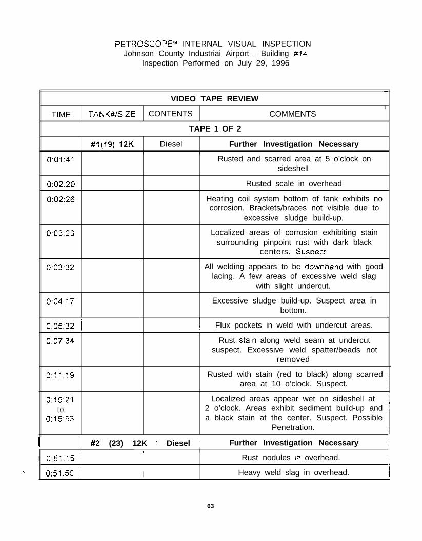
PETROSCOPE-” INTERNAL VISUAL INSPECTIONJohnson County Industriai Airport - Building #14
Inspection Performed on July 29, 1996
TIME
VIDEO TAPE REVIEW
TANK#/SIZE CONTENTS COMMENTS
TAPE 1 OF 2
#1(19) 12K Diesel Further Investigation Necessary
0:01:41 Rusted and scarred area at 5 o’clock onsideshell
0:02:20
0:02:26
Rusted scale in overhead
Heating coil system bottom of tank exhibits nocorrosion. Brackets/braces not visible due to
excessive sludge build-up.
0:03:23 Localized areas of corrosion exhibiting stainsurrounding pinpoint rust with dark black
centers. Susoect.
0:03:32 All welding appears to be downhand with goodlacing. A few areas of excessive weld slag
with slight undercut.
0:04:17 Excessive sludge build-up. Suspect area inbottom.
-
1
0:05:32 1
0:07:34
O:? 1:19
0:15:21to
0:16:53
! Flux pockets in weld with undercut areas.
Rust starn along weld seam at undercutsuspect. Excessive weld spatter/beads not
removed 1
Rusted with stain (red to black) along scarred jarea at 10 o’clock. Suspect. 1
Localized areas appear wet on sideshell at‘i2 o’clock. Areas exhibit sediment build-up and /
a black stain at the center. Suspect. Possible iPenetration. ;I
II ) #2 (23) 12K 1 Diesel 1 Further Investigation Necessary I/
I 0:51:15 jI I
Rust nodules In overhead. I
\ 0:51:50 i I Heavy weld slag in overhead. I/
63

VIDEO TAPE REVIEW
T I M E ( TANK#/SiZE CONTENTS COMMENTS
0 59:47 Excessive sludge in tank bottom around areaof coils/braces.
1.00:07 / Scarred area with dark red/black stain andsediment build-up at 3 o’clock. Suspect
1:05.37 I Possible pinholes on sideshell. Dark stain andsediment build-up at 3-5 o’clock.
No ingress of fluid observed.
1:11:37 Dark scar on steel (reddish brown to black)with sediment stain in bottom of tank at
5 o’clock. Suspect.
#3 (18) 12K Diesel Further Investigation Necessary
1:30:23 Excessive rust in overhead at both ends.
13142 Excessive film caused by heating throughouttank on sideshell beiow fuel level line. This
film has excessive trash encapsulation.Needs to be cleaned for further review.
1:35,18to
1: 3i:42
Scarring from CO, inerting process evident onsideshell at mid-tank.
1:37:55to
1:38:34
1:45:08
Wet area at seam weld on sideshell at3-9 o’clock. Further investigation of this area
is necessary.
Wet streaked areas with small pinhole ingressof fluid at 3 o’clock. Must be investigated
further.
1:50:41 Sediment build-up and stain on isolated area.No ingress at this spot. Mid-tank7 o’clock. 5-6 streaks. Suspect.
TAPE#Z OF 2
/ x4 (25) 12K / Diesel 1 Further Investigation Necessary
64

VIDEO TAPE REVIEW
TIME TANK$/SiZE CONTENTS COMMENTS
0:00:44 Heavy sludge In bottom and trashencapsulated film common to all tanks from 3-
8 o’clock.
0:01:32 Heavy build-up of rust and tubercles inoverhead around fill area. Suspect.
0:01:53t0
0:02:18
Rusted in overhead at south end of tank.Exhibits very large tubercle build-up.
0:08:05 Isolated area of wet streaks and sedimentbuild-up Stain in overhead at 11 o’clock on
southwest side at mid-tank. Heavy trashencapsulated in film appears to be lifting.
Condensation in several spots show noingress or movement.
0:19:20 Localized rusted area (heavy stains)mid-tank at 7 o’clock sideshell. Suspect.
0:20:31 Wet streaked area on sideshell southeast at 3o’clock.
0:21 :I4 Locakzed wet spot with sediment stain at5 o’clock in bottom sludge area. Observed no
movement.
0:21:23 Traces lead to area of excessive saltbuild-up at 3-5 o’clock. Highly suspect.
0:22:45 Two (2) areas of extreme saltkediment build-up at 9 o’clock No movement observed.
0:25:42 Localized areas of salt build-up fromto 3-5 o’clock and at 7 o’clock. Wet streaks but
0:27:29 no movement or ingress observed.
0:31:14 Some pitting on the transfer fuel lines and fillline.
#5 (24) 12K / Diesel Further Investigation Necessary
0:55:01 Several localized spots appear wet withand condensation beads in overhead. Highly
0:55.28 susoec:I
0:55:44 / , 1 HaIrlIne cracks tn film overhead.
65

,VIDEO TAPE REVIEW
j TIME TANK#ISlZE / CONTENTS / COMMENTS
0:57 53 Hairline cracks in film at 9 o’clock on sideshell.
, 1 02.49 / Film encapsulated with trash. Heavy fromII, I fluid level to bottom on both sides.
I 1:04.061:04.06 (I
1.05 361.05 36
Undercut along weld seam rusted. Somestain observed. Suspect.
Locaiized areas of salt build-up on sideshell at8 8 o’clock.
i 1:23:241:23:24 1
j 1.45 1.45 3232
1:51:241:51:24
i
Slight pitting on fuel lines.
Sediment stain and salts build-up on localizedarea of sideshell at 3 o’clock.
Film exhibits hairline cracks l/8” thick at 10o’clock.
6666

Tank Inspection Report
GardIler, Kansas Cit\*c
ARMORARMOR SHIELD. INC. . ATE. 2. BOX SHIELD. INC. . ATE. 2. BOX 1WA1WA . . FALUOUTH.FALUOUTH. KYKY 41040 , $06) w.&!~ FAX WJ~\ 654.4746

Introduction
This report is In regards to the knternai ~MpKtlol\ or 5 la~\ks lOC:\Kt\ ;\I \Ix JOI\I\SOII C‘OUI\I~ Ilrd\~s~rinlAirport facility in Gardner City. This inspcclion U’S pClfO~W!d b!, Annor Sh~cld. IIIC. III cooperationwit11 Double Check (Annor Shield Knnsas City) 2nd US IIIS~CCIIOII kn-ices
Description of Internal Inspection Methods
The inspection consisted of sandblnsting all the tanks and paforming ;I \~ISII~I lrlspcclion iI\ conlbillatioll
with various destructive and nondestnlctivc testing methods:
Destructive Mefhods:
Sandblasting
A brush blast was performed on lank numbers Is. 19. 20 :IIK! 24 T;lll1\ =li \\:I5 s.lllclbl;lslccl lo ;I ilenrwhite metal at the request of IvlRl. Xftcr tllc saiidblastili g \\;lS COlllI1IClC. 1112 I;lllhS \\CI-,’ \ ISUilII\’ Sc3llllCd
for corrosion holes. internal prttlng. and SC:IIII splits. Inlcmal pits \\crc ~~~c;~s~~rcrl USII~~ ;I \\’ R. ThorpeCo. Pit Gauge.
Hammer Testing
Ifscvere corrosion 111 ;lrens of the tank arc tdcrltlficd or ;Irc stlspcctsd ~II~III,” 111s \1511;11 IllspCctloll.
additional testing such as hnmmcr or otlxr destntcti\,c inspcctioii ICCIIIII~UCS 111x\ lx tlSctl IO I~CIIII~) ;1rc’:Iswhere severe corrosion nmy be tnklug place. Hamlcr ICSIIII,*I is SOIIWIIIICS used bciorc ;tbrm\~c bl;lStlrlg ;IS
nn Initial inspectton tool to opal up rust plugged I~OICS :IIICI 10 CUIII~IIC OIIIC~ ;I~<;IS \\ IIICII ;~ppc’;~r IO becorroded (Section AlO.3.l alid AlO.3.2 ofNLPA 631 :111d sccrioll C.1 3.J oi.API 05.;) NLP.4 63 Irequlrcs that ;lrcns around perfowtions bc sowtdcd [or thin mastSw!oIl X I(1 ? ;) .API 107 1 2lsorequires hl~~t~~cr testing around perfornlioils IO rcIIIo~‘c Ill111 IIICLII :III~ IO O~:IIII strllsluall! SOIIII~ cdgrls
around perforations (section 4.3.2.6 of API 1631). Tlrc lrn~nnw IN \\;Is lx~~~-o~mc‘d ;II 111~ rscpx of
MRI.
Nondestructive Methods:
Non destructi\.e test Incthods to dctcmllllc ~IIIIII,” \\Clc’ p~rl3rlllctl p111511;1111 -4 : 2 2 31’ -API 10: I
A magnetic flus inspcctlon nlztllod \\‘;Is used IO dctcrllllllc IIIC IIIXII I~IIC~IICSS 31‘ ~III.YI .IrC;ls TIIISntetllod in\.olved scnnnlng tltc surfncc of the I;III~ \\-ith ;I IILI~ICIIC 1l11.s dc\ ICC III COIII~III:IIIOII I! 1111
ultrasonic prove - up to determnc IIKI;I~ thickrlsss of p~ilc‘tl zrc;is
68

Alternntive non - destructi\,e rest =l:
Alternative non - destructive test ti2
An alrernarlve nondestnmlve lest 111e1hod \KIS performed ill rllc reqt~csl ol‘blR1 .AII ul!rxsorlic scan \\‘iisperformed on the tank. TIIISTIIIS waswas accolllpllshed b!. ~n;luc~:rl SC;IIIIIIII~ \\ II II XII LI/IKISOIIIC dc\ ice
honzonrally along the length of the tank at 1 ’ iumwls. This rcsullcd irl ;I 10~1 of 25 SCIII lines nlorrg thelength of the rank. Each scan line IITIS ;tppro.sitn;llel~~ ;I 1l-L” \I Idc and ulrmso~l~c ~IIIC~IICSS radlags \vere
taken every l/S” along the scan line. .\lRI had rcqucsted a 100”!~ sc;i11 of 111~ UII~ surfax II should benoted that to mspecr IOO?‘, of the tnllk stlrfxc. n dlffcrcur (ICI-ICC SIICII ;IS iI rmcr II~I~XOIIIC SGIIIIIIII~dewce would of been lnorc nppropnalc: IIo\\cwr. Arrlior Shrcld \\;Is 1101 prqxlrsd IO pcrfomi ;I lOO’%ullrnsonlc scan. Wliile rllis II~CCIIOII \\;Is 1101 ;I lOO% II~~I~;ISOIIIC SC;III II \\;iS IIIc’ 011lh III~~~~II~II iscIliod
11l;lt could be arranged g1w11 IIIC IIIIIC’ I‘I;IIIIC *II IIIC Silt
Non Destructive Testing Gencrnl Illl’orluntioll ;III~ Conlmeuts:
Conment 11
The mgnellc flus mspecllorl tnahod IS IIIC prlm:11?’ IN~IISII~ prxtlcc for dctcrrlllrlrllg IIILXII ~l~~ckncss of
pitted areas on eslsting steel stnaurcs IIIC~U~III~ plpclillcs a11tl abotL- grouild sIor~2C Lli1k bol~0~iIs.
Magnetic flus inspection IS co~nr~~onl!. wxd Ibr cornpl~;l~~ci‘ \\ 1111 L’II\ ~rou~wznul I.C~II~;IIIOIIS Tar thr:
aboveground storage talk and plpcli~~c itlcf~rs~t~ II IS ;llso [lx pr;tlur? 1qxct1011 KC~IIIO~O~! uxd forcompliimce t\ith API 653. API G52 1~1s S~IIII~;II. crIlcrI;I 10 ulldayol~rld m&S (.-\PI 1’15.: spc‘cltic’s a 100
mill minimum of steel) for cathodic prorcctioll. Essca~i:~ll!~. IIK .4m0r Shicld Ill:l~tlCIli lius qxclionmethod uSed for underground t;lnkS IS ;IIINOSI Icl~lllic:ll IO rl~;lr ~scd for J~J~\T~IWII~ t;lnkS ;Irld coqzhaaccwith API 65;.
This methodology is significntlll:. fxrcr ~II:III other itlspccttoll IKIII~I~UCS ar~cl IS IJCIII~ rljcd stlcc~ssfull!
for inspccrloli of nbo\,egrotiiid t;lnk bolIolllS ;llld ~I~C~IIIC-s III IIIC’ Un~tc’d SulCs ;IS \\clI ;lS Ililc’rli;llloii;ill~..
It is primnrily used iI1 ilmc mlrkcrs bsmm oi IIIC 01 c‘r;lll CoSi JfCcm mess ;IIKI ,I~IIII! IL) IIIU
cwiromentnl rcgulnllons nnd c^ollccrIIS Tic ~II.OIIIC’III;I~ rc’yl;1101~ oIqCc11\ c‘ ol‘rh~s~ IllduslriCs arcmost ldCrl[ml [O 111~’ objc’cttws of 111~ EPA rc’~tll;l~lons for tlluhyxx~rlcl I;III~\~
’
111 SllIlllll~lrl\. I1l~lgllCllC Ill!\: inSpm10ii is i.lirl:llli! I~L‘C~~III/L.I .IS 011i ol‘i11~ ~~LII~~I~;~ I .lll‘l 111~1~1 ax~1101111cll
inspection melhods lo :ISSC’SS J t;lltkS ;~~I!~IIIOII .III~ IO IIIC’J c‘:t\ II~III~III:~I I ,‘~lrl:lllull~ .llkl il~llic’l’llS
Amor Shield Ilad lnrewlcd oni! IO pcr<or.lll .I IKI~IIWC IIN\ IW+CC~IC)II. ir .Arlllol‘ slllclcl IUd beenno(lficd 111 nd\.:lllcc III;I~ h4Rl \t~lnrcd 10 pcrl‘orlll ;I IOO’!~;, u1tr;lsot1tc SC:III. .-\rluor Jhcltl \\auld ol’bc=u
69

prepared to perform such an inspection. If in the future EPA or MRI would lkc IO perform such a11
inspection, Armor Shield would be lvilling to do such an inspection.
Comment #3
In general, 100% ultrasonic scxuung and other ullrxonic testing wellrods arc outdared lccllnologies ;wd
are not state of the art in the industry for (his type of inspcctton. IMaguctic flus inspea~on is sIaIe of the
a~ and is the current lndusrry accepted prattcc for pcrforw1n,1’ IhIS I\-pe or Illspcclloll Ullrasonicscanning has limitations because it is inorc lime consuiniug lklll IllwJlcl\c ll\l.S.
Comment #I4
Magnetic flus inspection of abo\.cground lanks and pipelines rarely requrrcs sandbl;lsliljg (it should benoted that Armor Shield included sandblasting bccausc il IS rcquircd uodcr M-PA 63 1 ;Ind/or API IGj 1).This I-&IJCIS tile overall inspecl~oll time \zrsc’s 0Ihcr inspecrioa illClll0dS Sucli as iillrasonic scaiiniug
since not as 1m~c1~ cleanmg is required. A tank C:II~ be ulilgnclic flus inspccred in icss linlc than it rakes
to sandblast an entire tank.
Comment #5
Magnetic flu\: inspection will detect both internal and estcmal pitting as well as rust plugged holes OII
non sandblasted surfaces. Internal pilling and rusf plugged holes can be dificult to detect prior IO
sandblasting since rust plugged holes and IIIOSI inlcrnal pils m-e filled w111 n\sI or debris prior IO blasling.Ultrasonic scanning methods used still requires sandblas(iu y IO dcrccI iiilcmil ~IIIIII~ ;ind nlsf pluggedtype holes. In addition. ullnsomc SC~IIIUII,‘J \\,ould II:~\T :I d\ficulI! III O~XIIIUII~ rC;ldings from internal
pits or rust plugged holes filled wrh nw. The IMgIICIiC fl~r CZI~\ dcIccI nw plugged holes. cslcrnalpitting. and internal pitting c7s11y on non - snndblnsicd surlxcs and surfxes WIIICII III;I! 1101 othenvisc besuitable for oIher non-desImctn.e inspealon Il\CIl\ods such ;lj 1111r:lsonlc jc;1t\l\lll~
Comment #7
There were a few minor problculs Cncowlic‘rCd 011 I~IC SIIC \\ 1111 IlIC LXIIICP :rlld chic S!SI~III 01’111~
magnetic flus unit. ho\\,e\,er. llicsc problclns I~;I\ c ilo\\ bcCil rcsol\ Cd II sliould AISO lx rlolcd IIKII USInspections I\% i1 siinilnr l\\ilg\lCl\C flu\; \illII tILlI is 111iII\1l~lC~\II.CCi by 1111: S:lll1\: IIl;III\l~\CIIIrC~ ;lS ll\c 01X
Armor Shield used OII [his inspccIlon ;Il\d bo111 LIIIIIS ;lrc b;lsscl OII IIIC ZKICI j;lllW COlll(~OllCl\lS (billterics.coils, etc.). US inspecrions II;IS perfonucd nuuwous III:I~IIC’I~~ 1111\ IIIS~L’CIIOIIS oi ;~bo\ c’ywnd slor;lge~nnk bottoms with no equipnxnl problciiis h1;1y1c11c l111\ I! lx da IKS ;Irc \ cr? rcl~;hl~ ;III~ ;~c~t~;lll!- h;l\.r:better relinbllit!. rh11 olher ~ccl~~~olo~~cs SIICII ;IS ullrasoliiC j;:\111\111:
Conimeni #S
It should be noted that additional IIIW \vns spcnl on !liis SIW lor :I \ ancI? OC rcxons Illclud\ng pcrhrnrwg
multiple inspections OII rhe smc tnnk. performin g inspcccious \\411cl1 ArIl1or Slrxid \KIS IIOI prcprrcd 10perform but which MRI had rcquesred. \idco (\\ hich rcquir?d Artuor Shlcld psrsouncl IO opcr;rlc ;lndwhich stopped \vork 21 limes 011 olhcr 1;111ks :ls 111~ rcqucsI oI’ XlRl). IIIIIL’ COIISIIIIIII~~ C~C;IIIIII~ due IO thefact that Ihe tanks once cotmincd ntmbtr 4 fwl oil. viri (11 l~rclr caused \\‘:ilCr IO Cllic’r 1111: I;III~ ;ll‘lc’r
sandblasting and which was reblxtcd ;II IIIC rCqu~‘sI 01‘.\lRi I. ;llld OIIICI’ I~ICIOI.S \\,IIIc~I ;~rc‘ 1101 norm;lll!
encountcrcd on a i:picnl SIIC
Annor Shield bclievcs that uudcr nomal circuiimwccs :III iiirctml IIIS~~CIIOII oi :I I! l~c;~l UST SIIC(which uSwIly 113s 2 X 8 loc;ltioii) ulili/iil,” lIl:lgllcrIc Il\l\ \\OlllCl Llh2 110 111011’ 111;111 I &I\ IC rcqwtcd
by MRI. this can bc dclnonslrntcd b!, Ar111or Sl\iClcl AI XII a~u;~l ficltl or I<51 IOC:IIIOII
Comment 80
7 0

There !vas nn area in one of rile :nnks \\l~rch I\;IS IIIOI-c s~rt;~blc for ihc ILiIIIIIIIi‘r [LZSI ~\:)ILI;IIIOII and tolllusfrnte the purpose of tile l\nlumer [es;. The ;lrcn 111 111~ r2nk \\x st~sptclo~s In Ill:11 lliere \\wc severalholes in a s~nr~ll nren 2nd \\ilnt nppenred ro be ~IIIII II~C~;I~ bsr\\cc~l :llld nrorr~~d ll\e IIO~CS. This area wasnot hamner tesrcd nr ille req\lesr oi \lRl.
Comment # 10
Armor Shield cnn pro\ !de suppon~~lt! ;nformlnrioll rclntcd IO [lx ;~bo\~c Co\\ll\\cl\IS II reqtrcsIe:d by MRI.
Relavent Standards
Rehem SectIons or rclcrcllccd s~n~ldnrds ;IW II\CIUCICCI III :IIJ~CII~~I \ I
NLPA 63 1 - Third E~IIIOII
STPA 63 I - Four111 Edlrlon
API 163 1 - Third Editioll
API 653 - First Edirlcn
Criteria for Suitability:
IT’s letter dated July 25. 1396 described the crlterla for upgr:~dc for cathodic prolcclrorl. The let~cr statedthat “The meaning of the evaluation cr1rem (based OII b;lscllnc rcsis) for upgrading UST’s \ws clarified:each (not just one) of the crlrenn (I.e.. no corrosion holes. no sep;lr;l~ions in rank \\clds. no pi6 deeper .than .5 times the required mnin1utu \\all thickness. and ;n’erage \\.;lll thickness in caclr 3 f~ by 3 TI area ofat least SS% of rhe required nilllltnulll wall tl\~ck~\css) mm b\: I\ICI for ;I tank IO bc cohclcrcd upgndnblc.If n tank falls one or more of IIIC crllerm. in \\lli 1101 bc comdcrcd upgr;ld;tblc by c;lllloclic protcaiou.
Evaluation of Results by Tank Basis
This t~k \VCIS snndbhcd 211d ;l \.IsII;~~ III~XC~IOII \\,I5 I/CII p:rlwll~ci. TIC I;III~; \\;I5 r,ulld 1101 IO k
suilablc due IO tI\rortgh holes
Tank Number 19
71

Tank Number 20
This tank was sandblasted ;tt\d :\ \.ISU;I~ IIIS~CC~IOII ;\\\d ;I )XII’II:I~ IIU~IICIIC 1111x IIE+CCIIOII T!llj l;lllk \\JS
found not to be s\ri\able due to ~hrou$ I~o~cs.
Tank Number 24
Tl\is tank was sandblasted. visually inspected and al\ \\ltn\sonic SC;\I\ of the u\nk \\‘;\s perfor\\\cd b!uf~nic;llfy scanning tl\e entire lengtl\ of the tank at I‘ i\\tenr;\ls This talik N;\S four\d \\ot IO besuitable due to pitting that esceeded 50% of the nietal thickness.
Tank Number 25
Test #l - Visml and Mag\\et\c Flus
Tlus tat& was sandblasted. vist\:\lly impected. \\\\d H \\\r\g\\ctic (Ius i\\spec\io\\ \\‘;\s pcrfor\\\cd ot\ the t;\\\kon all accessible areas escept for a pOrtlO\ Of tile ti\\\k \vl\Cre OIli)’ 50% of tl\c :\rci\ \\‘;ts sc;\\\\\cd. Tl\ereason only a ponion of the tank surface \VX sc;\\\\\cd 50% was to dc\cr\\\\\\c if pi\\\\\g \\o\~ld SIIII bedetected witI\ only 50% of the surface bc\\\S sc;\\\l\cd. Tl\~s I:II\~ \\;\s Cou~\cl 1101 to bc s~~\;\blc d\lc toesternat and internal p\tting \I\;\\ csccccl~cl 3\‘lL
Test #2 - Visual and 3’ \: 3’ Grid
This tati tvas Visu;lll!’ lnspectcd ;\t\d ;\I\ \\ltr;\so\\\c ICSI hscd OII ;I 7’ \ .?,’ =*,l-ld \\ LIS pcl~lbllllcd Tills Iallk
was found not to be swtnble b!, tl\is \\\spcc\io\\ due 10 it\tcrt\:\l )III\II\ g \I\31 cxcccdcd iI)‘!;, of II\C ~~\ct;\lthickness and a red\\ct\o\\ of o\emll w;\lI tliickilcss ii\ cacl\ 3’ s 3’ grid :II tlic uonb cud of tl\c t:\\\k slrcllSpecifically, all \\ltr;\so\\ic tl\ickness rc:\di\\gs of II\C lirst ? or IIIC I;II\~ c!.l\\\dcr OII IIIC [\Ortl\ c\ld of tl\ctank indicate tl\ickness rcadiogs of less t/la\\ ST% of tlie IzI\~ mc~el tl\ick\\css (based 011 ;w origi\\;\l st\ellthickness of 260 n\ills). Tlrc ultrasonic rc;\di\\gs of the \\ortI\ e\\d cap ;IISO indlc;\tc ~IIIC~IICSS rc;\di\\gs orless than S5% of tl\e \\\\\\i\\\\\m nictal tliickiicss (this IS b:\scd OI\ thc co\\str\\ctio\\ of the SOIIIII cncl capwl\ich l\ad an or~ginnl \l\ick\\css ofnppro”\\l\;\tcl!’ ZSO 111111s) II Sll0uld bl: llotccl II\;11 7‘ K j‘ gridn\easure\\\e\\ts tlmt \\erc less tIl:\a SF%, OCII\C I\\L’I:\~ tliichicss \\crc’ 1101 Turtlxr Sllbd1\ ldctl ;\I IIIC rcq\\cS\ 01MRI.
General Summary of Results and Comments of InterestConcerning Evaluation
Location of Internal Corrosion
All tx\ks lrad severe 11rrcr1rn1 corros\o\\ Tl\s \\\os\ SS\ci\: III\~L’II;I/ iorrosloll III ;iII 01’111~ \;III~S \\:\s \oc:\\cuOI\ tl\e baton1 ortl\c t;l!\k ;\\\d \\;Is IIOI loc~ctl ~IITCI/~ IIII~~ 111s till OIIC‘IIIII~
Pitting
72

All tanks had estemnl plttlng greater r!lnn 50% of the ortglnnl 11x11 rhcklless and 2 or IIIC I;III~S hdinternal pltrmg wlucll \\ns grenter rl1311 in’!5 of the ~nctnl th~ckncss.
Holes
Visual Inspection
Both UST sites (and thus nil ranks) ucrc dclcrulwd unsu~~;~blc IJ! \ isual IIIS~CCIIOII. 0~ :III iildi\iduidbasis. 1 of the 5 tanks \\ere found IO be u~lsu~r;~blc by \.ISLI;II IIIS~~C~IOII.
Corrosion at the North End
All the tanks on the nonhem sire appear ro be espcricncing corrosiorl IO a illore se\‘erc degree ;I1 IhC IlORhend. All of the holes in these tanks were found OII the non11 end. It’s also inrcresliug IO note lhnf theultrasonic thickness readings from the 3 ’ s 3 ’ grid on tank #25 (\vh~ch is locnted 011 rhc south ate)indicate that all or pan of the nonh end of the ~auk shell IS less rlun S>’ -‘%, of tlrc IHC~I \lrickluzss.
Corrosion Line on Tank 25
73

Armor Shield Tank Inspection ReportAppendix I

The following materials were included in Armor Shield’s Appendix I:
NLPA 63 1. Entry, Cleaning, Interior Inspection, Repair and Lining of USTs. National
Leak Prevention Association 1991. Pages 13 and 85.
API Recommended Practice 163 1. Interior Lining of Underground Storage Tanks. Third
Ed. American Petroleum Institute. April 1992. Page 7.
API Standard 653. Tank Inspection, Repair, Alteration, and Reconstruction. First Ed.January 1991 (Incorporates Supplement 1. January 1992). American Petroleum Institute.Washington DC. page C-5.
75

Armor Shield Tank Inspection ReportAppendix II
76

ARMOR SHIELDTank #I 8
A BCDEFGHIJK
6
77
-
m Internal Corrosion Readings
m Holes -_

ARMOR SHIELDTank #I 9
E
N,
. . . . ~..
EA B C D E FGHIJK
78
m Magnetic Flux Inspectionm Internal Corrosion Readings
m Weld
m Holes~.

ARMOR SHIELDTank #I9
North End of Tank3 -_
( N S
/WI---
ii‘1\\‘\\\
1
+
Y)
T
\\\
\
79
1 m Magnetic Flux Inspection /

ARMOR SHIELDTank #20
E
EA BCDEFGHIJK
N 5-
7I
w
80
---..
m Magnetic Flux Inspectionm lnternai Corrosion Readings
m Holes ~--. .- -

ARMOR SHIELDTank #24
EA B C D E FGHIJK
N cm
cm 280 0501 OS0 0501 060 3701 080__ -.--- .___-_
6,060 35OI %I0 ,==J 060 070 1
7
8 /
- .-. --~-
9- ~ --- .__ _- -- .-
W
81m Internal Corrosion Readings

ARMOR SHIELDTank #25
82
agnetic Flux InspectionI m Internal Corrosion Readings
/ m 3’ x 3’ Grid Thickness Readings of less/ than 85Or6 of the original metal thickness

ARMOR SHIELDTank #25End Views
E-
N S
200 220
-----.-- - _.- --
North End
83__- -~-~
m 3’ x 3’ Grid Thickness Readings of lessthan 85% of the oriqinal metal thickness

- -_.--. ._ _ ._-_. -_... - ,734 ., - ___ __ - 4. .

Appendix C
Baseline Test Data
85

II Tank Location: New Century AirCenter, Gardner, Kansas
Data entered by:Mike Raile/Joe Hennon
ULTRASONIC INSPECTION FORM
Grih Grill Grih Grill GridSubgrid ci Subgrjd c; Subgrid 5 Subgrjd ci SubgridThick- Thick- Thick- Thick- Thick-
Grih Gria Grih Gric3 Grid-Subgrjd c( Subgrjrl CI Subgrjd 5 Subgrid c; Subgrjd qThick- Thick- Thick Thick- Thick-
Grih Griif Grih Grih Gri%Subgrjri 1 Subgrid 3 Subgrid 7 Subgrid 4 Subgrjd 6Thick- Thick- Thick Thick- Thick
Grih Grih Grih Grill GriaSubgrid 7 Subgrjd R Subgrjd 9 Subgrjd 5 Subgrid 4Thick- Thick- Thick.- Thick- Thick
Grih Grill Grih Grih GrihSubgrid 5 Subgrjd 5 Subgrjd 5 Subgrjd 5 Subgrid 5Thick- Thick- Thick-n Thick- Thick-
Grih Grill Grill Grill GrieSubgrFrt 5 Subgrid 5 Subgrjd ri Subgrid 1 Subgrjd 3Thick- Thick-0242 Thick Thick- Thic-
Grih Gria Grih Grih GriaSubgrid 3 Subgrjd 4 Subgrti 6 Subgrjd 7 Subgrjd RThick- Thick Thick- Thick- ThickAUlAL
Grih Grir3 Grill Grih GrihSubgrjd Q Subgrjd 1 Subgrid 3 Subgrjd 7 Subgrjd 4Thick- Thick- Thick-Cl245 Thick- Thick
Gri& Grill Grih Gri- GrihSubgrjd 6 Subgrjd 7 Subgrid A Subgrjd 9 Subgrjd 5Thick Thick& Thic- Thick- ThickAL2Adl
Grid Grih Grih Grih GriaSubgrjd 5 Subgrid 5 Subgrid q Subgrjd 5 SubgrMqThick- Thick- Thick Thick Thick
86

Tank No. 25
Date: g/12/96
Tank Location: New Century AirCenter, Gardner. Kansas II
11 Data entered by:M. Raile, J. Hennon 11
ULTRASONIC INSPECTION FORM
Grid- Grih Grih Gri% Grid rlnSubgrjd 4 Subgrid 5 Subgrjd 5 Subgrjd C; Subgrid 6Thic- Thick Thick- Thick- Thick-s
Grih Grih Gria Gria Grid-Subgrjd q Subgrjd 5 Subgrjd 5 Subgrjd 5 Subgrjd 5Thick- Thick- Thick Thick- Thick0 36~
Grid- Grill Gria Gria GridnlSubgrjd 5 Subgrti 5 Subgrid 5 Subgrirl 5 Subgrjd C;Thick- Thick Thick Thick11241 Thick-
Grid- Grih Grih Grih Grid-Subgrti 5 Subgrti 5 Subgrjd 5 Subgrjd 5 Subgrid C;Thick n 746 Thick- Thick- Thick- Thick-
Grid- Grih Grill Gria Gri%Subgrid 5 Subgrid 5 Subgrjd 5 Subgrjd 5 Subgrid 5Thick f~ 34a Thick- Thick- Thick- Thick-
Grid G3Grih Grill Grih GriaSubgrid 5 Subgrid q Subgrjd 5 Subgrid 5 Subgrjd qThick 0 30fi Thick- Thick- Thick- Thick-
Grid- Grih Grih Gria GriaSubgrjd 5 Subgrid 5 Subgrjd q Subgrid 5 Subgrid 5Thick n 3c;o Thick- Thick- Thick- Thick
Grid- Grih Gria Grih GriaSubgrjd q Subgrid 5 Subgrjd 5 Subgrjd 5 Subgrjd 5Thick-n 357 Thick- Thick- Thick- Thick
Grid POGrill Gria Grih Gri&Subgrjd 5 Subgrjd 5 Subgrid'? Subgrid 6 Subgrid qThick- Thick- Thick- Thick- Thick-n
Grid E3Gri& Grih Gri& GriaSubgrjd 5 Subgrjd q Subgrid 5 Subgrjd 5 Subgrid 5Thick n 3c;Q Thick- Thick- Thick Thick
87

ULTRASONIC INSPECTION FORM
Grid E7(Tri3 F,Q Grih Grid- Grid-Subgrid 5 Subgr!ti 5 Subgrid q Subgrjd 5 Subgrid NAThick.- Thick :! 765 Thick- Thick-a Thick fl 374
Grill Grid 3 GridL Grid- Grid .TSubgrid NA Subgr!ti NA Subgrjd NA Subgrjd NA Subgrid NAThick- Thick I) 37% Thick-m Thick n 376 Thick n 765
GridK Grih Grid- GriL G r i d -Subgrid NA Subgrid NA Subgrjd NA SubgrjdThick- Thick- Thick-n Thick
Subgrjd
I Thick
88

WALL THICKNESS FORM
Grid h Grid Ennrnn Grid GridSubgrid 5 Subgrid NA Subgrid SubgridThick. n Thick. n Thick. Thick.
GridSubgridThick.
89

Cl 11Data entered by: M. Raile, J. Hennon
\%‘ALL THICKNESS FORM
Grid h Grid Endun+ Grid GridSubgrid 5 Subgrid NA Subgrid SubgridThick. n Thick. n Thick. Thick.
GridSubgridThick.
90

IC II Tank Location: New Century Air
Center, Gardner, Kansas II
II Data entered by;M. Raile, J. Hennon II
WALL THICKNESS FORM
Grid L Grid m Grid GridSubgrid L Subgrid NA Subgrid SubgridThick . n Thick. n Thick. Thick.
GridSubgridThick.
91

Ii Tank No. 20
/I Date: 9/12/96
Tank Location: New Century AirCenter, Gardner, Kansas
Data entered by: M. Raile, J. Hennon
WALL THICKNESS FORM
Grid rrl Grid Endrsn Grid Grid GridSubgrid 5 Subgrid NA Subgrid Subgrid SubgridThick. n Thick. n387 Thick. Thick. Thick.
! 4
92

Cl ]IData entered by :J. Hennon, M. IXaile
PIT DEPTH FORM
Internal Pits
Note: Use three sections for the triplicate determinations of the 5 deepest pits.
Grid nln Grid nln Grid nln Grid GridSubgrid 9 Subgrid 9 Subgrid 9 Subgrid SubgridDepth n Depth 131)88 Depth nnhl Depth Depth
Grid D9 Grid h Grid D9 Grid GridSubgrid 8 Subgrid 8 Subgrid 8 SubgridSubgridDepth CI Depth a Depth QfNL- Depth Depth
Grid Eln Grid h Grid h Grid GridSubgrid 1 Subgrid 7 Subgrid 3 Subgrid Su bgridDepth C) Depth m Depth OAX!L- Depth Depth
Grid Eln Grid Eln Grid Eln Grid GridSubgrid L Subgrid L Subgrid L Subgrid Su bgridDepth % Depth % Depth n Depth Depth
G r i d E l G r i d E l G r i d F.1 in Grid GridSubgrid 3 Subgrid ? Subgrid 3 Subgrid SubgridDepth m Depth % Depth n Depth Depth
93

External Pits
Tank Location: New Century Air
Center, Gardner, Kansas
Data entered by: J. Hennon, J. Flora
PIT DEPTH FORM
Note: Use three sections for the triplicate determinations of the 5 deepest pits.
Grid R1 Grid L Grid R1Subgrid dc;, Subgrid c, Subgrid LDepth 03&- Depth n Depth r)
Grid V Grid Rh Grid RhSubgrid 7 Subgrid 7 Subgrid 7Depth I) Depth r) Depth m
GridSubgrid
&Pth
GridSubgridDepth
GridSubgridDepth
GridSubgridDepth
Grid RlnSubgrid LDepth nlsn
Grid Rln Grid Rln GridSubgrid 5 Subgrid 5 SubgridDepth n Depth W Depth
GridSubgridDepth
Grid LSubgrid -Depth m
Grid r7 inSubgrid -Depth nlsn
Grid c3 Grid L GridSubgrid 3 SubgridDepth r) Depth
Grid r7 inSubgrid 3Depth n189
GridSubgridDepth
GridSubgridDepth
GridSubgridDepth
Grid C7Subgrid LDepth s
Grid C17 Grid C17 GridSubgrid - Subgrid - SubgridDepth r) Depth n Depth
GridSubgridDepth
94

II Tank No. II
IllTank Location:New Century Air Center
Data entered by: JH & JF
TANK VISUAL INSPECTION FORM
In ternai/Ex tern alFY A b r a s i v e B l a s t e d ( Y / N ) h- P a g e 1
G r i d I D A l Percent Area Corroded In Subgrid of Large Dent
Hole Subgrid V. Deep Pit Subgrid 8(- Deep Pit Subgrid
Many Shallow Pits? 7Rr8 Pattern? General Corrosion?
Comments
G r i d I D A 3 Percent Area Corrode 1F Subgrid of Large Dent
Hole Subgrid V. Deep Pit Subgrid Deep Pit Subgrid glr)
Many Shallow Pits? 789 Pattern? General Corrosion?
Comments
G r i d I D A 3 Percent Area Corroded 31) Subgrid of Large Dent ,?
Hole Subgrid V. Deep Pit Subgrid Deep Pit Subgrid &&QO95&
Many Shallow Pits? 6789 Pattern? General Corrosion?
Comments
G r i d I D A d Percent Area Corroded 3n Subgrid of Large Dent ,G
Hole Subgrid V. Deep Pit Subgrid Deep Pit Subgrid 78
Many Shallow Pits? 147 Pattern? General Corrosion?
C o m m e n t s C~-Q=, 5 tig.h 7
Grid ID 2 Percent Area Corroded 71) Subgrid of Large Dent 3L
Hole Subgrid V. Deep Pit Subgrid U&UK& Deep Pit Subgrid 39
Many Shallow Pits? .- Pattern? General Corrosion? Ail
Comments v rllt nllt at ?,
95

TANK VISUAL INSPECTION FORM
Internal/External FrrPrnal Abrasive Blasted (Y/N) L Page 3
Grid ID h Percent Area Corroded 7F Subgrid of Large Dent .m
Hole Subgrid V . Deep Pit Subgrid L@In. Deep Pit Subgrid 65
Many Shallow Pits? J&Q- Pattern? General Corrosion?
.Comments c
Grid ID A7 Percen t Area Cor roded IF Subgrid of Large Dent
Hole Subgrid V. Deep Pit Subgrid 6% Deep Pit Subgrid 4,5&f&
Many Shallow Pits? 5.h.7. Pattern? General Corrosion?
Comments -hnPI In 7
G r i d I D A 8 Percent Area Corroded L Subgrid of Large Dent d
Hole Subgrid V. Deep Pit Subgrid 4,T (0 17) Deep Pit Subgrid 45JL~
Many Shallow Pits? Yes- Pattern? VllndPrrllt General Corrosion?
Con~~j~e~~ts rrfvw in 5 R, 6. <triunric in boitlle nf t~tfvial%
Grid ID A9 Percent Area Corroded 1F Subgrid of Large Dent
Hole Subgrid V. Deep Pit Subgrid. Deep Pit Subgrid
Many Shallow Pits? 4h Pattern? Qraiknc General Corrosion?
Comments Crpa~-, 4,5,h
Grid ID Aln Percent Area Corroded L Subgrid of Large Dent
Hole Subgrid V. Deep Pit Subgrid Deep Pit Subgrid 6JU88
Many Shallow Pits? All Pattern? General Corrosion?
Comments
96
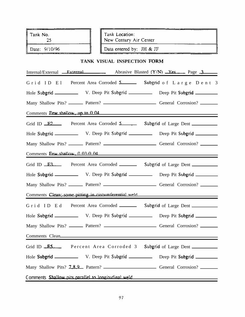
TANK VISUAL INSPECTION FORM
Internal/External F.Y Abrasive Blasted (Y/N) L Page -L,
G r i d I D E l Percent Area Corroded C Subgrid o f L a r g e D e n t 3
Hole Subgrid V. Deep Pit Subgrid Deep Pit Subgrid
Many Shallow Pits? Pattern? General Corrosion?
Comments Few v fl fld
Grid ID E3 Percent Area Corroded F Subgrid of Large Dent
Hole Subgrid V. Deep Pit Subgrid Deep Pit Subgrid
Many Shallow Pits? Pattern? General Corrosion?
Comments Few &.ULW. fl 07-n 04
Grid ID L Percent Area Corroded Subgrid of Large Dent
Hole Subgrid V. Deep Pit Subgrid Deep Pit Subgrid
Many Shallow Pits? Pattern? General Corrosion?
Comments ClPan: c- in rirrlllllfprPntial w&i
G r i d I D E d Percent Area Corroded Subgrid of Large Dent
Hole Subgrid V. Deep Pit Subgrid Deep Pit Subgrid
Many Shallow Pits? Pattern? General Corrosion?
Comments Clean
Grid ID L P e r c e n t A r e a C o r r o d e d 3 Subgrid of Large Dent
Hole Subgrid V. Deep Pit Subgrid Deep Pit Subgrid
Many Shallow Pits? 789~ Pattern? General Corrosion?
. .Comments -1 tn lnnPlrrlnlnnl]d
97

TANK VISUAL INSPECTION FORM
Internal/External W Abrasive Blasted (Y/NJ Ypp Page d
Grid ID L Percent Area Corroded Subgrid of Large Dent 37
Hole Subgrid V. Deep Pit Subgrid Deep Pit Subgrid
Many Shallow Pits’? L Pattern? General Corrosion?
Comments v\ tn WPI,L(O (IA\
Grid ID E7 Percent Area Corroded 5 Subgrid of Large Dent 35h
Hole Subgrid V Deep Pit Subgrid Deep Pit Subgrid
Many Shallow Pits’? J -l 7P a t t e r n ’ ? General Corrosion?
Comments (n 04)
Grid ID L Percent Area Corroded Subgrid of Large Dent
Hole Subgrid V. Deep Pit Subgrid Deep Pit Subgrid
Many Shallow Pits? - Pattern? General Corrosion?
Comments CleaizhnP
Grid ID F9 Percent Area Corroded
Hole Subgrid V. Deep Pit Subgrid,
Many Shallow Pits? - Pattern?
Comments HcxxnarL, In 7, 8
Subgrid of Large Dent
Deep Pit Subgrid
General Corrosion?
Grid ID Eln Percent Area CormdPn
Hole Subgrid V. Deep Pit Subgrid
Many Shallow Pits? - Pattern?
Subgrid of LargP
Deep Pit Subgrid
General Corrosion?
Comments Frfnliarirrn in 3, 5: chaq&m ~rpowfl
98

II Tank No. II
/IllI /I Tank location:New Century Air Center II
II Data entered by: JH & JF II
TANK VISUAL INSPECTION FORM
Internal/External e Abrasive Blasted (Y/N) Ypp Page ,L,
Grid ID nl Percent Area Corroded L Subgrid of Large Dent .-.
Hole Subgrid V. Deep Pit Subgrid Deep Pit Subgrid
Many Shallow Pits? Ypp Pattern? General Corrosion?
Comments fl fit -n fi3 : hoe3nark In 1 , 8
Grid ID n3 Percent Area Corroded In Subgrid of Large Dent
Hole Subgrid V. Deep Pit Subgrid Deep Pit Subgrid
Many Shallow Pits? 1-d Pattern? General Corrosion?
Comments L&crater 1 114 hv 1~
Grid ID D? Percent Area Corroded F Subgrid of Large Dent
Hole Subgrid V. Deep Pit Subgrid Deep Pit Subgrid
Many Shallow Pits? 3L3&5 Pattern? General Corrosion?
Comments 0 07
Grid ID nd Percent Area Corroded L Subgrid of Large Dent
Hole Subgrid V. Deep Pit Subgrid Deep Pit Subgrid
Many Shallow Pits? 234i Pattern? General Corrosion? 9
. .Comments rlirr.rr)sr nf Phalinwc In 3
Grid ID L Percent Area Corroded ? Subgrid of Large Dent
Hole Subgrid V. Deep Pit Subgrid D e e p P i t Subgrid 6 , 9 & l -*
Many Shallow Pits? 1378 Pattern? General Corrosion?
. .Comments .CpvpralQ. dfl waW fi w4-W in 6
99

TANK VISUAL INSPECTION FORM
Internal/External FY Abrasive Blasted (Y/N) Ypc Page L
Grid ID nh Percent Area Corroded L Subgrid of Large Dent
Hole Subgrid V. Deep Pit Subgrid Deep Pit Subgrid
Llany Shallow Pits? I? Pattern? General Corrosion?
Comments
Grid ID n7 Percent Area Corroded L Subgrid of Large Dent
Hole Subgrid V. Deep Pit Subgrid Deep Pit Subgrid
Many Shallow Pits? 1347 Pattern? Cirrlr in 7 General Corrosion?
Comments Pit< in 7 2qwld
Grid ID n8 Percent Area Corroded L Subgrid of Large Dent
Hole Subgrid V. Deep Pit Subgrid Deep Pit Subgrid
Many Shallow Pits? L Pattern? w 1 Rr A <n nd) General Corrosion?
Comments lkc&zed in 4
Grid ID L P e r c e n t A r e a C o r r o d e d 3 Subgrid of Large Dent
Hole S ubgrid V. Deep Pit Subgrid. Deep Pit Subgrid Q@f&&,
Many Shallow Pits? 3L Pattern? Lq+dkal in 4 General Corrosion?
Comments E.&k&nn in 3, 7
Grid ID nln Percent Area Corroded L Subgrid of Large Dent
Hole Subgrid V. Deep Pit Subgrid Deep Pit Subgrid
Many Shallow Pits? 1389 Pattern? General Corrosion?
Comments laqhdid flat dut&.uQ nq in ?
100

TANK VISUAL INSPECTION FORM
Internal/External FYtPtnsl Abrasive Blasted (Y/N) L Page 7
Grid ID R1 Percent Area Corroded L Subgrid of Large Dent ,&.
Hole Subgrid V. Deep Pit Subgrid Je Deep Pit Subgrid l-
Many Shallow Pits? L Pattern? General Corrosion?
Grid ID R3 Percent Area Corroded L Subgrid of Large Dent
Hole Subgrid V. Deep Pit Subgrid Deep Pit Subgrid 7aclsl
Many Shallow Pits? I-h& Pattern? General Corrosion?
Comments rirrlllnfPrPntisl 1-o
Grid ID R? Percent Area Corroded In Subgrid of Large Dent
Hole Subgrid V. Deep Pit Subgrid Many in o Deep Pit Subgrid
Many Shallow Pits? Pattern? General Corrosion?
. .Comments A V D +m Q stlJ1 has rnrrnplnnnrnnlrrttim: atb~rs n 14
Grid ID L Percent Area Corroded 1F Subgrid of Large Dent
Hole Subgrid V. Deep Pit Subgrid 3s~ Deep- Pit Subgrid lk
Many Shallow Pits? Pattern? General Corrosion?
Comments V n pits in 3 nv4aqqn.g: V D pit q/A &a, (0 15) at B&o fi ~35-7
Grid ID L Percent Area Corroded 3F Subgrid of Large Dent
Hole Subgrid V. Deep Pit Subgrid Deep Pit Subgrid 3s.
Many Shallow Pits? fpw Pattern? General Corrosion?
* .Comments Flr\Pmaritin n nltr In 3.1
101

TANK VISUAL INSPECTION FORM
Internal/External FvfPrnal Abrasive Blasted (Y/N) L Page L
Grid ID Rh Percent Area Corroded L Subgrid of Large Dent .&
Hole Subgrid V. Deep Pit Subgrid 179. Deep Pit Subgrid All
Many Shallow Pits? Pattern? General Corrosion?
. .- .Comments Cirr weld I 7. pitc have Inn~uu&nai wmlnnc, pt 0 1 F (9) fI 11% (7)
Grid ID -R7 Percen t Area Cor roded 70 Subgrid of Large Dent
Hole Subgrid V. Deep Pit Subgrid UfUQ5& Deep Pit Subgrid Is
Many Shallow Pits? - Pattern? f irr liup nf pit< in 1 ,7,8 General Corrosion?
. .Comments Hne mark in I ? ,Y: Tir WPM ? 9. hnri7 w&l 9: l3 nltc In 7&8 hAvP ctrl~nr- *
Grid ID R8 Percent Area Corroded F Subgrid of Large Dent
Hole Subgrid V. Deep Pit Subgrid Deep Pit Subgrid
Many Shallow Pits? 3189 Pattern? General Corrosion?
Comments Hnk20=ld 7-9: fwdqpiq nits in ?Rr?, 27fi9
Grid ID R9 P e r c e n t A r e a C o r r o d e d 3 Subgrid of Large Dent
Hole Subgrid V. Deep Pit Subgrid
Many Shallow Pits? Jh9 Pattern?
Deep Pit Subgrid
General Corrosion?
Comments Clirrld 3-R: lang2~h-t 7,R
Grid ID & Percent Area Corroded L Subgrid of Large Dent
Hole Subgrid V. Deep Pit Subgrid ?a Deep Pit Subgrid 9
Many Shallow Pits?. .
Pattern? &e&ppqg in 5 Rr in 9 General Corrosion?
102

TANK VISUAL INSPECTION FORM
Internal/External EvtPrnsl Abrasive Blasted (Y/N) L Page 9
Grid ID rl Percent Area Corroded 1c Subgrid of Large Dent -2
Hole Subgrid V. Deep Pit Subgrid Deep Pit Subgrid
Many Shallow Pits? b4zu1+ Pattern? General Corrosion?
. . . ..Comments Flrrpk A,7, rlrr pattern of WllnqW~, nvp.rlannln9&lnag-_nltc In 5,f;
Grid ID r3 Percent Area Corroded In Subgrid of Large Dent
Hole Subgrid V. Deep Pit Subgrid l$UX.Q~O. 15)Deep Pit Subgrid l-7
Many Shallow Pits? 47 Pattern? General Corrosion?
Comments fkerlqkg in 4,7: 4axueM T-9: bgseM 6
Grid ID c3 Percent Area Corroded L Subgrid of Large Dent
Hole Subgrid V. Deep Pit Subgrid 1s Deep Pit Subgrid? :
Many Shallow Pits? 7-h Pattern? General Corrosion?
Comments Hnri7 weld 4-f;: V n yiD in 1 nvd.appw~
Grid ID L Percent Area Corroded In Subgrid of Large Dent
Hole Subgrid V. Deep Pit Subgrid Deep.Pit Subgrid
Many Shallow Pits? U Pattern? General Corrosion?
Comments Hori7 weld 7-9: rirrld q-9
Grid ID rcS Percent Area Corroded 1 Subgrid of Large Dent
Hole Subgrid V. Deep Pit Subgrid Deep Pit Subgrid
Many Shallow Pits? 34 Pattern? General Corrosion?
Comments Flrrpk 5-R
103

TANK VISUAL INSPECTION FORM
Internal/External e Abrasive Blasted (Y/N) L Page In
Grid ID L Percent Area Corroded 5 Subgrid of Large Dent
Hole Subgrid V. Deep Pit Subgrid Deep Pit Subgrid
Many Shallow Pits? L Pattern? General Corrosion?
Comments Tir wf=M 1-7: hallnu&tc 3,3,4,5,8,9
Grid ID r7 Percent Area Corroded 5 Subgrid of Large Dent
Hole Subgrid V. Deep Pit Subgrid 3s Deep Pit Subgrid 3%
Many Shal low Pi ts? 7 Pat tern? General Corrosion?
.Comments Cirr weld 1-9: V I3 ni.f~ in ? fliffirlllrtnki, w-.
Grid ID L Percent Area Corroded In Subgrid of Large Dent
Hole Subgrid V. Deep Pit Subgrid 6&&L& Deep Pit Subgrid h05
Many Shallow Pits? LQ6 Pattern? General Corrosion?
.Comments V D >v
Grid ID r9 Percent Area Corroded 5 Subgrid of Large Dent
Hole Subgrid V. Deep Pit Subgrid Deep-Pit Subgrid l$L--
Many Shallow Pits? 13~5 Pattern? General Corrosion?
Comments Cirr \dleld 3-R. e in \yeld in 3
Grid ID cln Percent Area Corroded L Subgrid of Large Dent
Hole Subgrid V. Deep Pit Subgrid Deep Pit Subgrid
Many Shallow Pits? 3L5J3J Pattern? General Corrosion?
Comments Pitr 0 05
104

TANK VISUAL INSPECTION FORM
Internal/External EYtprnnj Abrasive Blasted (Y/N) L Page 11
Grid ID G1 Percent Area Corroded R Subgrid of Large Dent 1347.
Hole Subgrid V. Deep Pit Subgrid Deep Pit Subgrid
Many Shallow Pits? Pattern? General Corrosion?
Comments Rmlrp.n at endzap in 1 a%-hnfLmark In dz7
Grid ID c;3 Percent Area Corroded L Subgrid of Large Dent
Hole Subgrid V. Deep Pit Subgrid Deep Pit Subgrid [email protected]
Many Shallow Pits? 3LJLL Pattern? General Corrosion?
Comments rirr w.M 1-Q
Grid ID c;? Percent Area Corroded 3(1 Subgrid of Large Dent
Hole Subgrid V. Deep Pit Subgrid 4J.01 Deep Pit Subgrid d-
Many Shallow Pits? b-9 Pattern? General Corrosion?
.Comments Tank fI4k+lnn 89
Grid ID L Percent Area Corroded L Subgrid of Large Dent -G
Hole Subgrid V. Deep Pit Subgrid Deep-Pit Subgrid 5&.QU$
Many Shallow Pits? 32!,8Pattern? General Corrosion?
Comments r]jTFld 1-Q: eY in 7
Grid ID G Percent Area Corroded In Subgrid of Large Dent h
Hole Subgrid V. Deep Pit Subgrid S@l Deep Pit Subgrid Q(.Or)91
Many Shallow Pits? Yes- Pattern? General Corrosion?
. 9. .Comments Hw aad+, ~hl.riWn ?7,9, challnraLpitc 7,?,C,7,R
105

TANK VISUAL INSPECTION FORM
Internal/External EYfPrnal Abrasive Blasted (Y/N) Ypp Page 13
Grid ID L Percent Area Corroded L Subgrid of Large Dent Onp
Hole Subgrid L’. Deep Pit Subgrid Deep Pit Subgrid
Many Shallow Pits’? h-9 Pattern? General Corrosion?
C o m m e n t s Cirr wdd I 7 hnri;l ~~111 8.9: lnnv <trim h 9_
Grid ID c;7 Percent Area Corroded In Subgrid o f L a r g e D e n t Y e a
Hole Subgrid V. Deep Pit Subgrid Q$LQL?Z& Deep Pit Subgrid F
Many Shallow Pits? 5.8 Pattern? General Corrosion?
.COlnnlelltS rirr weid 7 9 hnri7 weIri 7 9 V TI nit< nvpw hnri7 strlwc_ - *
Grid ID c;8 Percent Area Corroded In Subgrid of Large Dent npntpll
Hole Subgrid V. Deep Pit Subgrid 32 Deep Pit Subgrid J-q
Many Shallow Pits? 18.9 Pattern? General Corrosion?
. .Comments kLne7 wdd 7-9: hne &&7
Grid ID & P e r c e n t A r e a C o r r o d e d 3 Subgrid of Large Dent ld7
Hole Subgrid V. Deep Pit Subgrid Js. Deep Pit Subgrid
Many Shallow Pits? 1LLL Pattern? General Corrosion?
Comments rirr hnri7- *
Grid ID r,ln Percent Area Corroded L Subgrid of Large Dent
Hole Subgrid V. Deep Pit Subgrid
Many Shallow Pits? 14 Pattern?
Deep Pit Subgrid
General Corrosion?
Comments
106

ICI II Tank Location:New Century Air Center II
II Data entered by: JH & MR II
TANK VISUAL INSPECTION FORM
Internal/External Fu Abrasive Blasted (Y/N) Ypp Page L
Grid ID w1 Percent Area Corroded 3 Subgrid of Large Dent 4&
Hole Subgrid V. Deep Pit Subgrid Deep Pit Subgrid
Many Shallow Pits? + Pattern? ,w,fb. General Corrosion?
.Comments w ~4 7 9, m-r pp ln 7: wpl+WCkS R,Q, llf* nff,- * . . . .
Grid ID H3 Percent Area Corroded L Subgrid of Large Dent .L
Hole Subgrid V. Deep Pit Subgrid Deep Pit Subgrid 4.&&Q&
Many Shallow Pits? L Pattern? 17_4 General Corrosion?
Comments J nnp ~-1~ 7 9- . 4,I rlr wplrl
Grid ID L Percent Area Corroded bn Subgrid of Large Dent GPnP.rall
Hole Subgrid V. Deep Pit Subgrid Deep Pit Subgrid 5.@&555
Many Shallow Pits? % Pattern?3Z? General Corrosion?
Comments FJnp_ke in 5 a R
Grid ID L Percent Area Corroded In Subgrid of Large Dent nPntPci
Hole Subgrid V. Deep Pit Subgrid Deep Pit Subgrid
Many Shallow Pits? L Pattern?lm General Corrosion?
Comments rir&Uhickn?-q’cc hnrp In 7
Grid ID F1s Percent Area Corroded 911 Subgrid of Large Dent Genera&
Hole Subgrid V. Deep Pit Subgrid Deep Pit Subgrid Z@Q,
Many Shallow Pits? GPn’l Pattern? nvPrlanninp General Corrosion?
Comments Hnanad A. . .- ’f(, Q in v ln A: I-IC prnncprl pit
Hl (can’t): 1 l/2” square weld patch between Al & Hl with possible pit under patch as perArmour Shield
107

TANK VISUAL INSPECTION FORM
Internal/External FY Abrasive Blasted (Y/N) L Page ld
Grid ID L Percent ,\rea Corroded L Subgrid of Large Dent nnplz
Hole Subgrid V . Deep Pit Subgrid Deep Pit Subgrid
Many Shallow Pits? Ypp Pattern? GPnPrni General Corrosion?
Comments rirr w&i 1 7. wf-lfl uatch in 3- .
Grid ID H7 Percent Area Corroded 15 Subgrid of Large Dent fkuzJax=,
Hole Subgrid V. Deep Pit Subgrid Deep Pit Subgrid 8(QUl55&
Many Shallow Pits? ?& Pattern? Extensive General Corrosion?
.Comments Hne mark in 6, r~r w&l ? 9, cnme mtc In 7- .
Grid ID w8 Percent Area Corroded hn Subgrid of Large Dent
Hole Subgrid V. Deep Pit Subgrid Deep Pit Subgrid 3
Many Shallow Pits? I-h Pattern? General Corrosion?
. . .Comments Wk iI1 d,h, ~xtm putpn&p nv4+ping fi bori7 ctrlstlnnc
Grid ID F19 Percent Area Corroded 35 Subgrid of Large Dent 69,
Hole Subgrid V . Deep Pit Subgrid Deep Pit Subgrid
Many Shallow Pits? % Pattern? t-6, 7,8 General Corrosion?
. .Comments H~UIU& in 6, c_lrrlCI 3 8, hnr U&I 7 ?, 7- * _. “ficPrn 9 #% A%?
Grid ID -HLQ- Percent Area Corroded 611 Subgrid of Large Dent 47,
Hole Subgrid V. Deep Pit Subgrid Deep Pit Subgrid
Many Shallow Pits? % Pattern? All subgrIds General Corrosion?
Comments Flnp w&i 1 3, 4 rlrr wdd l-11 n-9 fi A Ifi_ ’ ,t * -7.,HlO (can’t): hftmg lug between HlO-8 & AlO-2; 2” riser between HlO-9 & AlO-
108
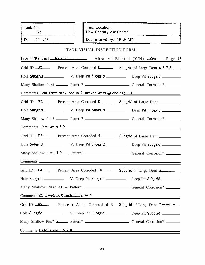
91 ]/TANK VISUAL INSPECTION FORM
IntemaI/Extemal EY Abras ive B las t ed (Y/N) k Page 15
Grid ID L Percent Area Corroded L Subgrid of Large Dent 4L.
Hole Subgrid V. Deep Pit Subgrid Deep Pit Subgrid
Many Shallow Pits? Pattern? General Corrosion?
.Comments Tear frnm-kck hw in 7, m in A
Grid ID F3 Percent Area Corroded L Subgrid of Large Dent
Hole Subgrid
Many Shallow Pits?
V. Deep Pit Subgrid
Pattern?
Deep Pit Subgrid
General Corrosion?
Comments f%r w&i 1-Q
Grid ID F? Percent Area Corroded L Subgrid of Large Dent
Hole Subgrid V. Deep Pit Subgrid Deep Pit Subgrid
Many Shallow Pits? 6-9 Pattern? General Corrosion?
Comments
Grid ID Fd Percent Area Corroded In Subgrid of Large Dent 9
Hole Subgrid V. Deep Pit Subgrid Deep-Pit Subgrid
Many Shallow Pits? AU.-- Pattern? General Corrosion?
Comments Cirrld q-9: f=yfnlistirrn in 6
Grid ID L P e r c e n t A r e a C o r r o d e d 3 Subgrid of Large Dent M.ll
Hole Subgrid V. Deep Pit Subgrid Deep Pit Subgrid
Many Shallow Pits? L Pattern? General Corrosion?
Comments ExUkin~ 1,5,7,8
109
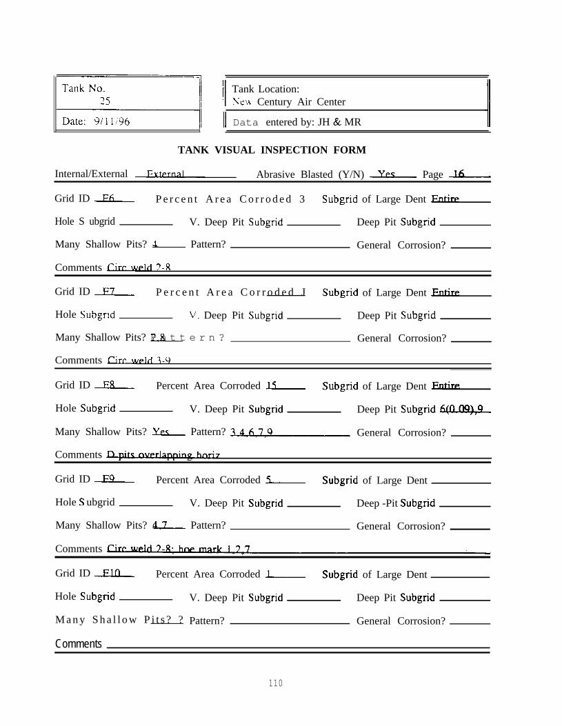
Sl II Tank Location:Ncu, Century Air Center
II Data entered by: JH & MR
TANK VISUAL INSPECTION FORM
Internal/External FYa, Abrasive Blasted (Y/N) L Page L
Grid ID Fh P e r c e n t A r e a C o r r o d e d 3 Subgrid of Large Dent Entire
Hole S ubgrid V. Deep Pit Subgrid Deep Pit Subgrid
Many Shallow Pits? ti Pattern? General Corrosion?
Comments fire weld 3-g
Grid ID F7 P e r c e n t A r e a C o r r o d e d J Subgrid of Large Dent Entirp.
Hole Subgrid V. Deep Pit Subgrid Deep Pit Subgrid
Many Shallow Pits? 7.8P a t t e r n ? General Corrosion?
Comments Cirr weld 7-9
Grid ID F8 Percent Area Corroded L Subgrid of Large Dent Eatire
Hole Subgrid V. Deep Pit Subgrid Deep Pit Subgrid &no\
Many Shallow Pits? % Pattern?-a General Corrosion?
Comments IX@ ovPrtanninp7
Grid ID F9 Percent Area Corroded L Subgrid of Large Dent
Hole S ubgrid V. Deep Pit Subgrid Deep -Pit Subgrid
Many Shallow Pits? 47 Pattern? General Corrosion?
Comments Cirr WW
Grid ID Fin Percent Area Corroded J- Subgrid of Large Dent
Hole Subgrid V. Deep Pit Subgrid Deep Pit Subgrid
M a n y S h a l l o w P i t s ? ? Pattern? General Corrosion?
Comments
110

TANK VISUAL INSPECTION FORM
In temal/Extemal TntPrnal Abrasive Blasted (Y/N) L Page 1
G r i d I D A l Percent Area Corroded L Subgrid of Large Dent
Hole Subgrid V. Deep Pit Subgrid Deep Pit Subgrid
Many Shallow Pits? Pattern? General Corrosion?
Comments Cle-n
G r i d I D A 3 Percent Area Corroded L Subgrid of Large Dent
Hole Subgrid V. Deep Pit Subgrid Deep Pit Subgrid
Many Shallow Pits? Yp. Pattern? General Corrosion?
. .Comments AlLpits in l,T,T (~~Uagej, c1u‘ weld
G r i d I D A ? Percent Area Corroded ?n Subgrid of Large Dent 74L
Hole Subgrid V. Deep Pit Subgrid Deep Pit Subgrid
Many Shallow Pits? L Pattern? General Corrosion?
Comments Shak~+c In I,?,? v 1lnP hnttnm of o
G r i d I D A d Percent Area Corroded 3F Subgrid of Large Dent .&
Hole Subgrid V. Deep Pit Subgrid Deep Pit Subgrid
Many Shallow Pits? Ypp Pattern? Flnri7 General Corrosion?
. .Comments Pit< in 1,3,1 !ul&@m&q of 4+~x w&i
G r i d I D A S Percent Area Corroded 311 Subgrid of Large Dent
Hole Subgrid V. Deep Pit Subgrid Deep Pit Subgrid
Many Shallow Pits? Ypp Pattern? General Corrosion?
.Comments 3 rllt aul fnr lnnnway, h2llw-p 1,7,(q)
111

TANK \‘ISUAL INSPECTION FORM
Internal/External lntPrnal A b r a s i v e B l a s t e d ( Y / N ) L P a g e 3
Grid ID Af; Percent Area Corroded II Subgrid of Large Dent df;
Hole Subgrid V. Deep Pit Subgrid Deep Pit Subgrid
Many Shallow Pits? Ypc Pattern? General Corrosion?
.Comments rirr Rt hnr ylpkis: hnPrk< 1 ,4 nit< 1-?,F III&I~P\ 1 rllt mlt fnr IIUJUGIV
Grid ID 47 Percent Area Corroded 21) Subgrid of Large Dent 7
Hole Subgrid V. Deep Pit Subgrid Deep Pit Subgrid
Many Shallow Pits? YPqP a t t e r n ? General Corrosion?
.Comments rirr and hnr weld<: d&Luqut< in 1 7 ‘3 @.&qe\
G r i d I D A 8 Percent Area Corroded L Subgrid of Large Dent 4-7
Hole Subgrid V. Deep Pit Subgrid Deep Pit Subgrid
Many Shallow Pits? yp_F Pattern? General Corrosion?
Comments ShalInw ?itc &mnn~ nf I ? ? 1i&yb
Grid ID A9 Percent Area Corroded In Subgrid of Large Dent 1L
Hole Subgrid V. Deep Pit Subgrid, Deep.Pit Subgrid
Many Shallow Pits? % Pattern? General Corrosion?
. .Comments w=tnrltc ha&&anf 1 3 ?
Grid ID Aln Percent Area Corroded L Subgrid of Large Dent L
Hole Subgrid V. Deep Pit Subgrid Deep Pit Subgrid
Many Shallow Pits? L Pattern? General Corrosion?
Comments Hm7 wplfl, dkallm&~ 1,3,1 @lap\
112

/I Tank Location :New Century Air Center I/
II Data entered by: JH & MR II
TANK VISUAL INSPECTION FORM
Internal/External TnrPrnal Abrasive Blasted (Y/N) Ypp Page L
Grid ID R1 Percent Area Corroded R Subgrid of Large Dent .L
Hole Subgrid V. Deep Pit Subgrid Deep Pit Subgrid
Many Shallow Pits? Pattern? General Corrosion?
Grid ID R3 Percent Area Corroded L Subgrid of Large Dent
Hole Subgrid V. Deep Pit Subgrid Deep Pit Subgrid
Many Shallow Pits? Pattern? General Corrosion?
Grid ID R7 Percent Area Corroded Subgrid of Large Dent
Hole Subgrid V. Deep Pit Subgrid Deep Pit Subgrid
Many Shallow Pits? Pattern? General Corrosion?
Grid ID Rd Percent Area Corroded Subgrid of Large Dent
Hole Subgrid V. Deep Pit Subgrid Deep Pit Subgrid
Many Shallow Pits? Pattern? General Corrosion?
Grid ID L Percent Area Corroded Subgrid of Large Dent
Hole Subgrid V. Deep Pit Subgrid Deep Pit Subgrid
Many Shallow Pits? Pattern? General Corrosion?
Comments Slit aw frnln UT in 7
113

TANK VISUAL INSPECTION FORM
Internal/External TntPrnal Abrasive Blasted (Y/N) Ypo Page d
Grid ID Rh Percent Area Corroded Subgrid of Large Dent
Hole Subgrid V. Deep Pit Subgrid Deep Pit Subgrid
Many Shallow Pits? - Pattern? General Corrosion?
Comments rfZcn.rrnQitim tIT In Wor 7 8.
Grid ID R7 Percent Area Corroded Subgrid of Large Dent
Hole Subgrid V. Deep Pit Subgrid Deep Pit Subgrid
Many Shallow Pits’? - Pattern? General Corrosion?
Comments Cir W-IA J-9. <fir rnrr trnm 1~ In 3,4,5 ,h.R
Grid ID R8 Percent Area Corroded Subgrid of Large Dent
Hole Subgrid V . Deep Pit Subgrid Deep Pit Subgrid
Many Shallow Pits? - Pattern? General Corrosion?
Comments frnr weId 7-9
Grid ID R9 Percent Area Corroded Subgrid of Large Dent
Hole Subgrid V. Deep Pit Subgrid Deep. Pit Subgrid
Many Shallow Pits? - Pattern? General Corrosion?
Comments Tir w&i T-8: weld-&c In 1 a 3: hnr In 7&g
Grid ID Rln Percent Area Corroded Subgrid of Large Dent
Hole Subgrid V. Deep Pit Subgrid Deep Pit Subgrid
Many Shallow Pits? - Pattern? General Corrosion?
Comments IIT rnrr in ~5
114

/I Tank No.II II
Tank Location :25 New Century Air Center /I
Date: 9112196II II
Data entered by: JH & MR
TANK VISUAL INSPECTION FORM
Internal/External lntprnal Abrasive Blasted (Y/N) k Page L
Grid ID rln Percent Area Corroded Subgrid of Large Dent
Hole Subgrid V. Deep Pit Subgrid Deep Pit Subgrid
Many Shallow Pits? Pattern? General Corrosion?
Comments None
Grid ID Co Percent Area Corroded
Hole Subgrid V. Deep Pit Subgrid
Many Shallow Pits? Pattern?
Comments rir weld 3-8
Subgrid of Large Dent
Deep Pit Subgrid
General Corrosion?
Grid ID (18 Percent Area Corroded Subgrid of Large Dent
Hole Subgrid V. Deep Pit Subgrid Deep Pit Subgrid
Many Shallow Pits? Pattern? General Corrosion?
Comments mne
Grid ID r7 Percent Area Corroded
Hole Subgrid V. Deep Pit Subgrid
Many Shallow Pits? Pattern?
Comments rir weld ‘3-9: 1~ CPU in 7
Grid ID rfi Percent Area Corroded
Hole Subgrid V. Deep Pit Subgrid
Many Shallow Pits? Pattern?
Comments WC w&-i 3-g
Subgrid of Large Dent
Deep Pit Subgrid
General Corrosion?
Subgrid of Large Dent
Deep Pit Subgrid
General Corrosion?
115

TANK VISUAL INSPECTION FORM
Internal/External InrPrnal Abrasive Blasted (Y/N) Jks-- Page h
Grid ID CF Percent Area Corroded Subgrid of Large Dent
Hole Subgrid V. Deep Pit Subgrid Deep Pit Subgrid
Many Shallow Pits? Pattern? General Corrosion?
Comments N.WP
Grid ID .L Percent Area Corroded Subgrid of Large Dent
Hole Subgrid V. Deep Pit Subgrid Deep Pit Subgrid
M a n y S h a l l o w P i t s ? Pattern? General Corrosion?
Comments rir w~lfl 1-9: hnr w&l d&5
Grid ID .r? Percent Area Corroded Subgrid of Large Dent
Hole Subgrid V. Deep Pit Subgrid Deep Pit Subgrid
Many Shallow Pits? Pattern? General Corrosion?
11 . .Comments Hnr~ki A 6. m rrvi up tn 104 , llvnc W&W In ‘i_* .
Grid ID r3 Percent Area Corroded Subgrid of Large Dent 47,
Hole Subgrid V. Deep Pit Subgrid, Deep-Pit Subgrid
Many Shallow Pits? Pattern? General Corrosion?
Comments Cir wf4-l 7-9
Grid ID L Percent Area Corroded Subgrid of Large Dent 6i
Hole Subgrid V. Deep Pit Subgrid Deep Pit Subgrid
Many Shallow Pits? Pattern? General Corrosion?
Comments bbp
116

TANK VISUAL INSPECTION FORM
Internal/External W Abrasive Blasted (Y/N) L Page 7
Grid ID nl Percent Area Corroded Subgrid of Large Dent e
Hole Subgrid V. Deep Pit Subgrid Deep Pit Subgrid
Many Shallow Pits? Pattern? General Corrosion? All
Grid ID n3 Percent Area Corroded Subgrid of Large Dent
Hole Subgrid V. Deep Pit Subgrid Deep Pit Subgrid 7(nQ
Many Shallow Pits? Pattern? General Corrosion? 7Fi
Grid ID n? Percent Area Corroded Subgrid of Large Dent
Hole Subgrid V. Deep Pit Subgrid Deep Pit Subgrid
Many Shallow Pits? 7Q$- Pattern? General Corrosion? 5no/n
Grid ID L Percent Area Corroded
Hole Subgrid V. Deep Pit Subgrid
Many Shallow Pits? -7-9~ Pattern?
Subgrid of Large Dent
Deep Pit Subgrid
General Corrosion? a
Comments rir w&t T-9: hnr W&I 7: weld 1ly In ~9
Grid ID L Percent Area Corroded Subgrid of Large Dent
Hole Subgrid V. Deep Pit Subgrid Deep Pit Subgrid
Many Shallow Pits? 44,LL Pattern? General Corrosion? bno/,
Comments Nr wplfi 1 ?, w4d d spkOr In 5- *
117

TANK VISUAL INSPECTION FORM
Internal/External e Abrasive Blasted (Y/N) L Page L
Grid ID nh Percent Area Corroded
Hole Subgrid V. Deep Pit Subgrid
Many Shallow Pits? - Pat tern?
Subgrid of Large Dent
Deep Pit Subgrid
Gene ra l Co r ro s ion? d -9
Comments Cir weld l-7: hnr I ,7 8: w~ldhy 7828
Grid ID n7 Percent Area Corroded Subgrid of Large Dent
Hole Subgrid V. Deep Pit Subgrid Deep Pit Subgrid
Many Shallow Pits? Pattern? General Corrosion? %
Comments I&U weid 7 9, rir weIrI_ . 7 9 w~L61LLp9 in ‘3. qhnrt hm & 6. wdd in ‘5- .
Grid ID n8 Percent Area Corroded Subgrid of Large Dent
Hole Subgrid V. Deep Pit Subgrid Deep Pit Subgrid
Many Shallow Pits? 5&U Pattern? General Corrosion? a
Comments Her w+I 4-h
Grid ID L Percent Area Corroded Subgrid of Large Dent
Hole Subgrid V. Deep Pit Subgrid Deep-Pit Subgrid &!2(s/nnol
Many Shallow Pits? 7-9 Pattern? General Corrosion? ?n9G,
Comments rir w&l 3-8: hnr w&l A,‘F: w~ldinglrrgs 7&R- wplrl
Grid ID nln Percent Area Corroded Subgrid of Large Dent
Hole Subgrid V. Deep Pit Subgrid 9&LQ-- Deep Pit Subgrid 9&06&
Many Shallow Pits? 78 Pattern? General Corrosion? d-Q(M
I,Comments Y n Fit ?/ 16 rfia, Ifi l/4 frmuu,&q, R l/7 fq&uUnm C 1 :DlO (can’t): also a 0.125 pit 0.125 dia, 7 l/2” from end cap, 11” from C.L.; D pit 318 dia, 11”from E.C., 2” from C.L.
118

TANK VISUAL INSPECTION FORM
Internal/External TntPrnal Abrasive Blasted (Y/N) L Page 9
Grid ID Eln Percent Area Corroded Subgrid of Large Dent
Hole Subgrid V. Deep Pit Subgrid 5/nl Deep Pit Subgrid 3@0,
Many Shallow Pits? Pattern? General Corrosion? %
Grid ID E9 Percent Area Corroded Subgrid of Large Dent
Hole Subgrid V. Deep Pit Subgrid
Many Shallow Pits? F Pattern?
Deep Pit Subgrid 5@Q
General Corrosion? 5L.
Comments Tir WeId i-7
Grid ID -Ek-- Percent Area Corroded
Hole Subgrid V. Deep Pit Subgrid
Many Shallow Pits? G Pattern?
Comments UnP
Grid ID F7 Percent Area Corroded
Hole Subgrid V. Deep Pit Subgrid
Many Shallow Pits? 32 Pattern?
Comments Cir weld-~-9: wpld lug In 5
Grid ID L Percent Area Corroded
Subgrid of Large Dent
Deep Pit Subgrid- :
General Corrosion? c
Subgrid of Large Dent h
Deep Pit Subgrid
General Corrosion? l-6
Subgrid of Large Dent 137
Hole Subgrid V. Deep Pit Subgrid Deep Pit Subgrid
Many Shallow Pits? Pattern? General Corrosion? lU@Q%J
Comments fir weld l-7: hnr w&i in 7
El0 (can’t): V D pit l/8” wide x i/4” long, 11” from EC, 17 l/2” from CL; 2 D pits 3/16” dia,5 l/2” from EC, 15” from CL; also D pit in 5 (0.07)
119

TANK VISUAL INSPECTION FORM
Internal/External m Abrasive Blasted (Y/N) L Page In
Grid ID -E5-- Percent Area Corroded Subgrid of Large Dent h
Hole Subgrid V. Deep Pit Subgrid Deep Pit Subgrid TL(~
Many Shallow Pits? F Pattern? General Corrosion? %
Comments Hnr \bielrl 7 - .R, w~lrf rw~r in 5
Grid ID E4 Percent Area Corroded Subgrid of Large Dent
Hole Subgrtd V Deep Pit Subgrid Deep Pit Subgrid ?(CI
Many Shallow Pits? J-2&21 Pattern? General Corrosion? %
Comments Tir ti 1-Q. hnr weid in 9
Grid ID L Percent Area Corroded Subgrid of Large Dent
Hole Subgrid V. Deep Pit Subgrid Deep Pit Subgrid ?-4(n Q8J-
Many Shallow Pits? All Pattern? General Corrosion? L
Comments
Grid ID F3 Percent Area Corroded Subgrid of Large Dent
Hole Subgrid V. Deep Pit Subgrid Deep Pit Subgrid 2&LQc
Many Shallow Pits? ~13 Pattern? General Corrosion? 3FZ
Comments rir welfl h-9
G r i d I D E l Percent Area Corroded Subgrid of Large Dent
Hole Subgrid V. Deep Pit Subgrid Deep Pit Subgrid 3/n&~
Many Shallow Pjts? l&L Pattern? General Corrosion? s
Comments -0
120

TANK VISUAL INSPECTION FORM
Internal/External TntPrnal Abrasive Blasted (Y/N) Ypp Page 11
Grid ID F1 Percent Area Corroded Subgrid of Large Dent 478-
Hole Subgrid V. Deep Pit Subgrid Deep Pit Subgrid
Many Shallow Pits? Pattern? General Corrosion? h
Comments Renf fi Ezir in 7
Grid ID F3 Percent Area Corroded Subgrid of Large Dent
Hole Subgrid V. Deep Pit Subgrid Deep Pit Subgrid
Many Shallow Pits? Pattern? General Corrosion?
Grid ID F? Percent Area Corroded Subgrid of Large Dent
Hole Subgrid V. Deep Pit Subgrid Deep Pit Subgrid
Many Shallow Pits? Pattern? General Corrosion?
Comments None
Grid ID Fd Percent Area Corroded Subgrid of Large Dent
Hole Subgrid V. Deep Pit Subgrid Deep .Pit Subgrid
Many Shallow Pits? Pattern? General Corrosion?
Comments rir 3-9
Grid ID L Percent Area Corroded Subgrid of Large Dent hf5
Hole Subgrid V. Deep Pit Subgrid Deep Pit Subgrid
Many Shallow Pits? Pattern? General Corrosion?
Comments hkw
121

Cl Tank Location:New Century Air Center
Data entered bv: JH & MR
TANK VISUAL INSPECTION FORM
Internal/External Intprn;ll Abrasive Blasted (Y/N) Ypc Page 13
Grid ID Fh Percent Area Corroded Subgrid of Large Dent b
Hole Subgrid V. Deep Pit Subgrid Deep Pit Subgrid
Many Shallow Pits? - Pattern? General Corrosion?
Comments M;rinrrlpnt: rlr weld 1 7. u&Llw 7&f?- .
Grid ID F7 Percent Area Corroded
Hole Subgrid V. Deep Pit Subgrid
Many Shallow Pits? - Pattern?
Comments hlnue
Subgrid of Large Dent 7
Deep Pit Subgrid
General Corrosion?
Grid ID F8 Percent Area Corroded
Hole Subgrid V. Deep Pit Subgrid
Many Shallow Pits? - Pattern?
Subgrid of Large Dent
Deep Pit Subgrid
General Corrosion?
Comments hlnop
Grid ID F9 Percent Area Corroded Subgrid of Large Dent
Hole Subgrid
Many Shallow Pits?
Comments rir w&i 7-g
V. Deep Pit Subgrid Deep Pit Subgrid
Pattern? General Corrosion?
Grid ID Fin Percent Area Corroded
Hole Subgrid V. Deep Pit Subgrid
Many Shallow Pits? ~ Pattern?
Corn ments bhw
Subgrid of Large Dent
Deep Pit Subgrid
General Corrosion?
122

TANK VISUAL INSPECTION FORM
Internal/External e Abrasive Blasted (Y/N) L Page L
Grid ID Gin Percent Area Corroded Subgrid of Large Dent
Hole Subgrid V. Deep Pit Subgrid Deep Pit Subgrid
Many Shallow Pits? Pattern? General Corrosion?
Comments l!Ionp
Grid ID G9 Percent Area Corroded
Hole Subgrid V. Deep Pit Subgrid
Many Shallow Pits? Pattern?
Comments rir weld 3-R: bnr W+-I In 7
Subgrid of Large Dent
Deep Pit Subgrid
General Corrosion?
Grid ID L Percent Area Corroded
Hole Subgrid V. Deep Pit Subgrid
Many Shallow Pits? Pattern?
Comments HW wpld 7-9
Subgrid of Large Dent Rr7
Deep Pit Subgrid
General Corrosion?
Grid ID G7 Percent Area Corroded Subgrid of Large Dent m
Hole Subgrid V. Deep Pit Subgrid Deep Pit Subgrid
Many Shallow Pits? Pattern? General Corrosion?
Comments rir weld 1-9: horh
Grid ID Gfi Percent Area Corroded Subgrid of Large Dent I&U&
Hole Subgrid V. Deep Pit Subgrid Deep Pit Subgrid
Marty Shallow Pits? ? Pattern? General Corrosion?
. . ’Comments Fir wt4A l-7, 1 IT rnff in 6, PIJQ In nnnt
123

TANK VISUAL INSPECTION FORM
Internal/External TnrPrnal Abrasive Blasted (Y/N) Ypp Page L
Grid ID L Percent Area Corroded Subgrid of Large Dent Qne4U
Hole Subgrid V. Deep Pit Subgrid Deep Pit Subgrid
Many Shallow Pits? 1 Pattern’? General Corrosion?
Comments
Grid ID (34 Percent Area Corroded 1 Subgrid of Large Dent v
Hole Subgrid V. Deep Pit Subgrid Deep Pit Subgrid
Many Shallow Pits? i Pattern? General Corrosion?
Comments Yitq in w- IIT rnrr in 5
Grid ID & Percent Area Corroded Subgrid of Large Dent
Hole Subgrid V. Deep Pit Subgrid Deep Pit Subgrid
Many Shallow Pits? Pattern? General Corrosion?
Comments IIT rnrr in AfieF
Grid ID -GZL- Percent Area Corroded
Hole Subgrid V. Deep Pit Subgrid
Many Shallow Pits? Pattern?
. .Comments JlT rnrr in A,T,h,7, rlr w&l 1-9
Grid ID L Percent Area Corroded
Hole Subgrid V. Deep Pit Subgrid
Many Shallow Pits? Pattern?
Comments IIT rnrr in ?.f;,Q
Subgrid of Large Dent
Deep Pit Subgrid
General Corrosion?
Subgrid of Large Dent ,1347,
Deep Pit Subgrid
General Corrosion?
124

TANK VISUAL INSPECTION FORM
Internal/External e Abrasive Blasted (Y/N) A Page ,L
Grid ID L Percent Area Corroded Subgrid of Large Dent
Hole Subgrid V. Deep Pit Subgrid Deep Pit Subgrid
Many Shallow Pits? 83. Pattern? General Corrosion?
Comments Flrrp.k In 4: hnr 7 9, 11T rnrr H9#c In u.l&suw- - . . .
Grid ID F13 Percent Area Corroded U@lage) Subgrid of Large Dent
Hole Subgrid V. Deep Pit Subgrid Deep Pit Subgrid
Many Shallow Pits? 7-9 Pattern? General Corrosion?
Comments Her wplrf A 6, rlr w4UaW 7&R: wplrl !fl I! In 9- .
Grid ID H? Percent Area Corroded L Subgrid of Large Dent 7-Q
Hole Subgrid V. Deep Pit Subgrid Deep Pit Subgrid
Many Shallow Pits? 4a Pattern? lnngkikl General Corrosion?
Comments Pitr in 7-9 in ulby
Grid ID Fld Percent Area Corroded rl Subgrid of Large Dent 7
Hole Subgrid V. Deep Pit Subgrid Deep -Pit Subgrid
Many Shallow Pits? L Pattern? General Corrosion?
Comments Cir wf+i q-9: hnrp In 8
Grid ID L Percent Area Corroded L Subgrid of Large Dent 89
Hole Subgrid V. Deep Pit Subgrid Deep Pit Subgrid
Many Shallow Pits? ,a Pattern? General Corrosion?
. * .Comments Manwsv wtnuingnrt~ In ulkv
125

TANK VISUAL INSPECTION FORM
InternaFExternal e Abrasive Blasted (Y/N) L Page L
Grid ID Hh Percent Area Corroded 3Ll@L@e) Subgrid of Large Dent La@+--
Hole Subgrid V. Deep Pit Subgrid Deep Pit Subgrid
Many Shallow Pits? All Pattern? General Corrosion?
Grid ID H7 Percent Area Corroded ?n Subgrid of Large Dent h
Hole Subgrid V. Deep Pit Subgrid Deep Pit Subgrid
Many Shallow Pits? All Pattern? General Corrosion?
.Comments Psrf nf rnrra.unn~,llllaPP sra mr \areld 3-9
Grid ID L Percent Area Corroded Subgrid of Large Dent
Hole Subgrid V. Deep Pit Subgrid Deep Pit Subgrid
Many Shallow Pits? Pattern? General Corrosion?
Comments None
Grid ID F19 Percent Area Corroded Subgrid of Large Dent
Hole Subgrid V. Deep Pit Subgrid Deep Pit Subgrid
Many Shallow Pits? Pattern? General Corrosion?
Grid ID Flln Percent Area Corroded
Hole Subgrid V. Deep Pit Subgrid
Many Shallow Pits? Pattern?
Comments ?” ricfv in 8. 7” rir \4lelrl in 9
Subgrid of Large Dent 7
Deep Pit Subgrid
General Corrosion?
126