Delamination Behaviour of Embedded Polymeric Sensor and ...
13
polymers Article Delamination Behaviour of Embedded Polymeric Sensor and Actuator Carrier Layers in Epoxy Based CFRP Laminates—A Study of Energy Release Rates Andreas Hornig 1, * , Anja Winkler 1 , Eric Bauerfeind 2 , Maik Gude 1 and Niels Modler 1 Citation: Hornig, A.; Winkler, A.; Bauerfeind, E.; Gude, M.; Modler, N. Delamination Behaviour of Embedded Polymeric Sensor and Actuator Carrier Layers in Epoxy Based CFRP Laminates—A Study of Energy Release Rates. Polymers 2021, 13, 3926. https://doi.org/10.3390/ polym13223926 Academic Editors: Phuong Nguyen-Tri and Tuan Anh Nguyen Received: 22 September 2021 Accepted: 9 November 2021 Published: 13 November 2021 Publisher’s Note: MDPI stays neutral with regard to jurisdictional claims in published maps and institutional affil- iations. Copyright: © 2021 by the authors. Licensee MDPI, Basel, Switzerland. This article is an open access article distributed under the terms and conditions of the Creative Commons Attribution (CC BY) license (https:// creativecommons.org/licenses/by/ 4.0/). 1 Institute of Lightweight Engineering and Polymer Technology (ILK), Technische Universität Dresden, Holbeinstraße 3, 01307 Dresden, Germany; [email protected] (A.W.); [email protected] (M.G.); [email protected] (N.M.) 2 AB Elektronik Sachsen GmbH, Salzstraße 3, 01774 Klingenberg, Germany; [email protected] * Correspondence: [email protected]; Tel.: +49-351-463-38007 Abstract: Fiber reinforced composites combine low density with high specific mechanical properties and thus became indispensable for today’s lightweight applications. In particular, carbon fibre reinforced plastic (CFRP) is broadly used for aerospace components. However, damage and failure behaviour, especially for complex fibre reinforcement set-ups and under impact loading conditions, are still not fully understood yet. Therefore, relatively large margins of safety are currently used for designing high-performance materials and structures. Technologies to functionalise the materials enabling the monitoring of the structures and thus avoiding critical conditions are considered to be key to overcoming these drawbacks. For this, sensors and actuators are bonded to the surface of the composite structures or are integrated into the composite lay-up. In case of integration, the impact on the mechanical properties of the composite materials needs to be understood in detail. Additional elements may disturb the composite structure, impeding the direct connection of the composite layers and implying the risk of reducing the interlaminar integrity by means of a lower delamination resistance. In the presented study, the possibility of adjusting the interface between the integrated actuator and sensor layers to the composite layers is investigated. Different polymer layer combinations integrated into carbon fibre reinforced composite layups are compared with respect to their interlaminar critical energy release rates G Ic and G IIc . A standard aerospace unidirectionally reinforced (UD) CFRP prepreg material was used as reference material configuration. The investigations show that it is possible to enhance the mechanical properties, especially the interlaminar energy release rate by using multilayered sensor–actuator layers with Polyimide (PI) outer layers and layers with low shear stiffness in between. Keywords: sensor embedding; carrier foil; function-integrative composites; integrated sensor sys- tems; intelligent composites; delamination behaviour 1. Introduction Against the backdrop of the scarcity and rising cost of natural resources, the opti- mization of material and energy efficiency is increasingly coming to the fore of science and industry in technology, more than ever before. Advanced lightweight design con- cepts are developed for production systems and manufacturing technologies as well as for the use and operation of structures and components. High energy saving potentials with simultaneous pollutant reduction promise material-efficient lightweight solutions with a considerable weight reduction of moving components and systems. In this con- text, fibre-reinforced composites offer the possibility of adapting the material properties to the specific requirements regarding mechanical [1] and other functionalities, such as appropriate tribological [2] or even ecological compatibility [3]. The relatively new group of textile-reinforced plastics offers particular advantages for complex applications, espe- Polymers 2021, 13, 3926. https://doi.org/10.3390/polym13223926 https://www.mdpi.com/journal/polymers
-
Upload
khangminh22 -
Category
Documents
-
view
1 -
download
0
Transcript of Delamination Behaviour of Embedded Polymeric Sensor and ...
polymers
Article
Delamination Behaviour of Embedded Polymeric Sensor andActuator Carrier Layers in Epoxy Based CFRP Laminates—AStudy of Energy Release Rates
Andreas Hornig 1,* , Anja Winkler 1 , Eric Bauerfeind 2, Maik Gude 1 and Niels Modler 1
�����������������
Citation: Hornig, A.; Winkler, A.;
Bauerfeind, E.; Gude, M.; Modler, N.
Delamination Behaviour of
Embedded Polymeric Sensor and
Actuator Carrier Layers in Epoxy
Based CFRP Laminates—A Study of
Energy Release Rates. Polymers 2021,
13, 3926. https://doi.org/10.3390/
polym13223926
Academic Editors: Phuong
Nguyen-Tri and Tuan Anh Nguyen
Received: 22 September 2021
Accepted: 9 November 2021
Published: 13 November 2021
Publisher’s Note: MDPI stays neutral
with regard to jurisdictional claims in
published maps and institutional affil-
iations.
Copyright: © 2021 by the authors.
Licensee MDPI, Basel, Switzerland.
This article is an open access article
distributed under the terms and
conditions of the Creative Commons
Attribution (CC BY) license (https://
creativecommons.org/licenses/by/
4.0/).
1 Institute of Lightweight Engineering and Polymer Technology (ILK), Technische Universität Dresden,Holbeinstraße 3, 01307 Dresden, Germany; [email protected] (A.W.);[email protected] (M.G.); [email protected] (N.M.)
2 AB Elektronik Sachsen GmbH, Salzstraße 3, 01774 Klingenberg, Germany; [email protected]* Correspondence: [email protected]; Tel.: +49-351-463-38007
Abstract: Fiber reinforced composites combine low density with high specific mechanical propertiesand thus became indispensable for today’s lightweight applications. In particular, carbon fibrereinforced plastic (CFRP) is broadly used for aerospace components. However, damage and failurebehaviour, especially for complex fibre reinforcement set-ups and under impact loading conditions,are still not fully understood yet. Therefore, relatively large margins of safety are currently used fordesigning high-performance materials and structures. Technologies to functionalise the materialsenabling the monitoring of the structures and thus avoiding critical conditions are considered tobe key to overcoming these drawbacks. For this, sensors and actuators are bonded to the surfaceof the composite structures or are integrated into the composite lay-up. In case of integration,the impact on the mechanical properties of the composite materials needs to be understood indetail. Additional elements may disturb the composite structure, impeding the direct connectionof the composite layers and implying the risk of reducing the interlaminar integrity by means ofa lower delamination resistance. In the presented study, the possibility of adjusting the interfacebetween the integrated actuator and sensor layers to the composite layers is investigated. Differentpolymer layer combinations integrated into carbon fibre reinforced composite layups are comparedwith respect to their interlaminar critical energy release rates GIc and GI Ic. A standard aerospaceunidirectionally reinforced (UD) CFRP prepreg material was used as reference material configuration.The investigations show that it is possible to enhance the mechanical properties, especially theinterlaminar energy release rate by using multilayered sensor–actuator layers with Polyimide (PI)outer layers and layers with low shear stiffness in between.
Keywords: sensor embedding; carrier foil; function-integrative composites; integrated sensor sys-tems; intelligent composites; delamination behaviour
1. Introduction
Against the backdrop of the scarcity and rising cost of natural resources, the opti-mization of material and energy efficiency is increasingly coming to the fore of scienceand industry in technology, more than ever before. Advanced lightweight design con-cepts are developed for production systems and manufacturing technologies as well asfor the use and operation of structures and components. High energy saving potentialswith simultaneous pollutant reduction promise material-efficient lightweight solutionswith a considerable weight reduction of moving components and systems. In this con-text, fibre-reinforced composites offer the possibility of adapting the material propertiesto the specific requirements regarding mechanical [1] and other functionalities, such asappropriate tribological [2] or even ecological compatibility [3]. The relatively new groupof textile-reinforced plastics offers particular advantages for complex applications, espe-
Polymers 2021, 13, 3926. https://doi.org/10.3390/polym13223926 https://www.mdpi.com/journal/polymers
Polymers 2021, 13, 3926 2 of 13
cially in the fields of aerospace, automotive, marine and mechanical engineering, medicaltechnology and sports equipment [4–6]. In this context, such parts were further modifiedby adhesively bonding of additional functional elements to the composite structure orintegrating them into the composite lay-up [7–14]. In most cases, these elements representsensors, actuators, conductive paths, and small electronic elements. They can be used fordifferent purposes, once they enable the monitoring of the composite structures and allowa forecast of damage propagation or failure [10,15,16].
The second purpose is to use these elements as an internal measurement system forseveral tasks, e.g., temperature, strain or impact detection [11–14]. In most cases, thefunctional elements are not directly embeddable in the lay-up. With regard to electricalinsulation and high positional accuracy, these elements can be pre-assembled to functionallayers, consisting of electrical insulating cover layers and the functional elements [17–19].In this context, textile-reinforced plastics show decisive advantages compared to con-ventional construction materials. Primarily, they consist of a layered lay-up, enabling arelatively easy insertion of additional layers. The second main advantage is that they onlyneed very low manufacturing temperatures compared to metals. Thus, a wide variety ofmodern flat functional elements, such as sensors, actuators, antennas and generators canbe integrated directly into the manufacturing process of the textile-reinforced components,which enables further weight and performance advantages of the resulting light-weightsystem [10].
However, the opportunities offered by this modern combination of materials alsopresent new challenges that the fibre composite engineer has to face. This also includesmanufacturing-specific aspects such as the integration of sensor and actuator elements intothe structure of fibre composite components and its influence on the manufacturing or de-sign process as well as on the mechanical properties [9,20,21]. In this context, several studieswere made with regard to designing suitable smart components [9,22,23], adapted man-ufacturing technologies for function-integrative structures [17,24] and their experimentalcharacterization [15,25,26]. Common materials are composites of glass fiber reinforced ther-mosets (mainly epoxy resins) or thermoplastics (e.g., polyamides, polypropylene). In manyworks, the elements are integrated directly into the composite or adhesively bonded to it.Here, the matrix systems used and the cladding layers of the functional elements them-selves act as insulation material. If additional carrier or insulating films are used, these areusually thin films of polyimide e.g., in the case of the SMART Layer™ technology [18,19] orembeddable sensor layers [23].
In particular, the use of CFRPs yields further requirements. The reason for this is inparticular the electrical conductivity of the carbon fibers used. Therefore, suitable conceptsfor the electrical insulation of the integrated elements (e.g., sensors, actuators, conductivepaths) are required. Electrical and electronic components and especially the electricalcontacting areas, e.g., for connecting the power supply or external measuring devices, haveto be electrically insulated appropriately. Studies on the integration of large insulationlayers and their impact on the composite properties of CFRPs are only marginally describedin literature [18,19,21,27,28].
This paper deals with the use of large and composite adapted active layers enablingproper electrical insulation of all elements to the CFRPs as well as high mechanical proper-ties of such function-integrative composites. It presents investigations for the integration ofdifferent plastic films, in the function of an electrical insulation layer, and the characteriza-tion of their influence on the mechanical properties of the composite material. The analysisof the modified composites is based on suitable methods for evaluation and validation ofmechanical properties and aspires to point out the limits of the corresponding materialconfigurations. Particular attention is paid to minimizing the influence on the mechanicaland interlaminar properties of the modified CFRP composites.
Polymers 2021, 13, 3926 3 of 13
2. Embedded Polymer Carrier Layers2.1. Investigated Material and Embedding Configurations
To investigate the influence of different polymeric layers integrated in CFRP compositepanels, different setups are conceptualized, manufactured and tested. The experimentalinvestigations aim towards a characterization of the bonding behaviour and are based onfracture mechanical experiments (see Section 3). This requires a crack initiation which isrealised in all investigated configurations by the use of Polytetraflourethylene (PTFE) foilinsertion, which acts as the crack initiation layer. Different polymeric materials are chosento investigate their embedding behaviour in varying lay-up configurations. The followingengineering polymeric foils are considered:
• Polyimide (PI),• Polyether-Ether-Ketone (PEEK),• Polyamide (PA),• Polyetherimide (PEI),• additional Polyolefine (PO) layer.
These potential materials feature a sufficiently high heat resistance and can thereforeresist the CFRP manufacturing process of the composite material undamaged. Additionally,they fulfill the requirements of electrical insulation for sensors, actuators and conductivepath integration.
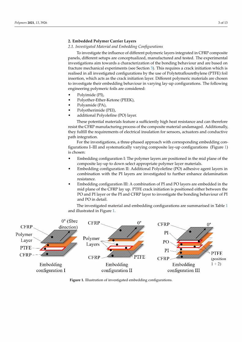
For the investigations, a three-phased approach with corresponding embedding con-figurations I–III and systematically varying composite lay-up configurations (Figure 1)is chosen:
• Embedding configuration I: The polymer layers are positioned in the mid plane of thecomposite lay-up to down select appropriate polymer layer materials.
• Embedding configuration II: Additional Polyolefine (PO) adhesive agent layers incombination with the PI layers are investigated to further enhance delaminationresistance.
• Embedding configuration III: A combination of PI and PO layers are embedded in themid plane of the CFRP lay up. PTFE crack initiation is positioned either between thePO and PI layer or the PI and CFRP layer to investigate the bonding behaviour of PIand PO in detail.
The investigated material and embedding configurations are summarised in Table 1and illustrated in Figure 1.
Figure 1. Illustration of investigated embedding configurations.

Polymers 2021, 13, 3926 4 of 13
Table 1. Investigated material and embedding configurations.
Material Polymer Layer Embedding Layer Thickness Crack InitiationConfiguration Configuration [µm] between
1 PI I 125 CFRP2 PEEK I 100 CFRP3 PA I 100 CFRP4 PEI I 100 CFRP5 PI-PO-PI II 350 (125 + 100 + 125) CFRP6 PI-PO-PI * II 150 (25 + 100 + 25) CFRP7 PO-PI-PO II 325 (100 + 125 + 100) CFRP8 PI-PO-PI III 350 (125 + 100 + 125) PI and PO9 PI-PO-PI III 350 (125 + 100 + 125) PI and CFRP
10 none reference - CFRP* The PI layers are coated with an acrylate adhesive on the CFRP facing side.
2.2. Manufacturing of CFRP Panels with Embedded Layers and Specimen Preparation
The CFRP panels are manufactured by hot pressing technology. Standard aerospaceUD prepreg HexPly® 8552 is used for configuration I and II (single layer thickness 130 µm,30 layers). CYCOM® 977-2 UD CFRP-prepreg is used for configuration III and a referenceconfiguration (layer thickness 184µm, 20 layers). The fibre direction is chosen for the crackpropagation direction Figure 1. In total, 10 panels with dimensions of 295 mm × 295 mm× 3.8 mm for each the 10 investigated material configurations (Table 1) are manufactured.
A CNC cutter is used to cut the layers to size in an automated manner. Afterwards, theprepreg and polymer layers are stacked and pre-compacted manually. The consolidationis performed by a heated compressing and a hot pressing mould under defined pressureand temperature conditions according to the manufacturing specifications of the prepregmaterials: compacting under vacuum and 7 bar pressure, curing at 110 ◦C for 60 min andpostcuring at 180 ◦C for 120 min, both under vacuum and pressure. After consolidationand demoulding, the panels are water jet cut into the final specimen configuration (seeSection 3).
To examine the delamination behaviour, Double-Cantilever Beam (DCB) and End-Loaded Split (ELS) specimens are prepared. The load application to these specimensis realised by adhesively bonded aluminium loading blocks (Figure 2). To ensure anoptimal bonding between CFRP and aluminium, the surfaces of both joining partnerswere pre-treated before the adhesive was applied. The joining surfaces of the CFRP testspecimens were first ground using sandpaper with a grain size of 320P. After cleaning withacetone, both the aluminium blocks and the CFRP joining surfaces were blasted with aglass bead size of 40–70µm. Subsequently, the joining partners are manually joined using aCyanoacrylate based adhesive that cures at ambient temperature.
Figure 2. Loading block configuration for (a) DCB and (b) ELS specimens.
3. Determination of Delamination Characteristics3.1. Experimental Programme and Setup
Two different experimental procedures are employed to characterize the impact ofthe embedded polymer layers on the interlaminar fracture characteristics. Mode I criticalenergy release rates GIC are determined using the DCB test based on [29], whereas the ELStest is used for mode II critical energy release rates GI Ic based on [30]. Pre-cracks of 70 mmare realised by embedded PTFE foils in the midplane (see Figure 1). In total, 80 tests are
Polymers 2021, 13, 3926 5 of 13
performed (8 per material configuration 1–10, Table 1). An overview is given in Table 2. Allexperiments are performed under displacement control at a constant rate of 10 mm/minand standard climate conditions (23 ◦C ± 2 ◦C, 50 ± 5% relative humidity).
Table 2. Specimen configurations.
Specimen Dimensions [mm3] Total Quantity (per Material Configuration)
DCB 277 × 25 × 3.8 40 (4)ELS 277 × 25 × 3.8 40 (4)
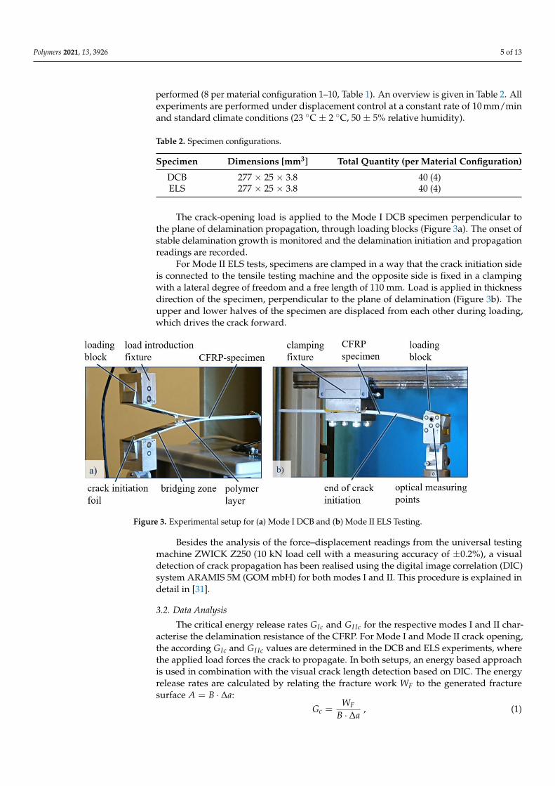
The crack-opening load is applied to the Mode I DCB specimen perpendicular tothe plane of delamination propagation, through loading blocks (Figure 3a). The onset ofstable delamination growth is monitored and the delamination initiation and propagationreadings are recorded.
For Mode II ELS tests, specimens are clamped in a way that the crack initiation sideis connected to the tensile testing machine and the opposite side is fixed in a clampingwith a lateral degree of freedom and a free length of 110 mm. Load is applied in thicknessdirection of the specimen, perpendicular to the plane of delamination (Figure 3b). Theupper and lower halves of the specimen are displaced from each other during loading,which drives the crack forward.
Figure 3. Experimental setup for (a) Mode I DCB and (b) Mode II ELS Testing.
Besides the analysis of the force–displacement readings from the universal testingmachine ZWICK Z250 (10 kN load cell with a measuring accuracy of ±0.2%), a visualdetection of crack propagation has been realised using the digital image correlation (DIC)system ARAMIS 5M (GOM mbH) for both modes I and II. This procedure is explained indetail in [31].
3.2. Data Analysis
The critical energy release rates GIc and GI Ic for the respective modes I and II char-acterise the delamination resistance of the CFRP. For Mode I and Mode II crack opening,the according GIc and GI Ic values are determined in the DCB and ELS experiments, wherethe applied load forces the crack to propagate. In both setups, an energy based approachis used in combination with the visual crack length detection based on DIC. The energyrelease rates are calculated by relating the fracture work WF to the generated fracturesurface A = B · ∆a:
Gc =WF
B · ∆a, (1)
Polymers 2021, 13, 3926 6 of 13
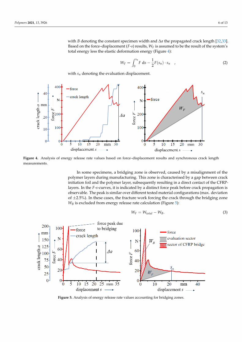
with B denoting the constant specimen width and ∆a the propagated crack length [32,33].Based on the force–displacement (F-s) results, WF is assumed to be the result of the system’stotal energy less the elastic deformation energy (Figure 4):
WF =∫ sn
0F ds − 1
2F(sn) · sn , (2)
with sn denoting the evaluation displacement.
Figure 4. Analysis of energy release rate values based on force–displacement results and synchronous crack lengthmeasurements.
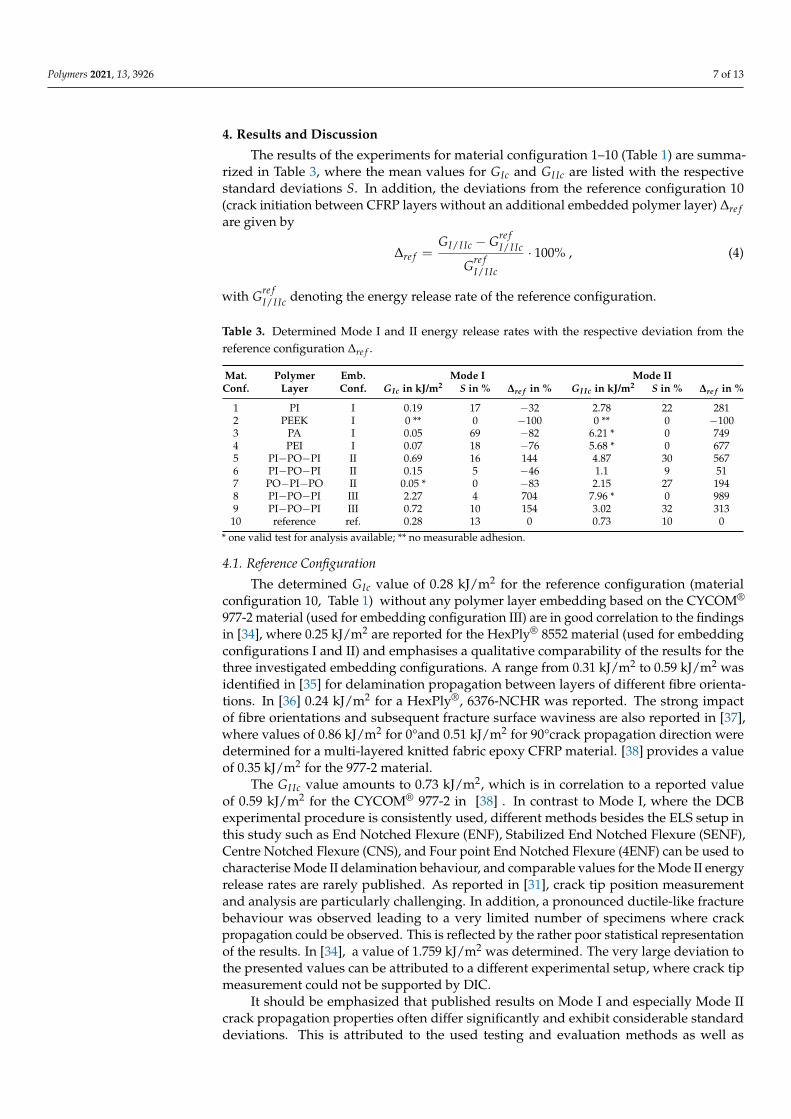
In some specimens, a bridging zone is observed, caused by a misalignment of thepolymer layers during manufacturing. This zone is characterised by a gap between crackinitiation foil and the polymer layer, subsequently resulting in a direct contact of the CFRP-layers. In the F-s-curves, it is indicated by a distinct force peak before crack propagation isobservable. The peak is similar over different tested material configurations (max. deviationof ±2.5%). In these cases, the fracture work forcing the crack through the bridging zoneWB is excluded from energy release rate calculation (Figure 5):
WF = Wtotal − WB. (3)
Figure 5. Analysis of energy release rate values accounting for bridging zones.
Polymers 2021, 13, 3926 7 of 13
4. Results and Discussion
The results of the experiments for material configuration 1–10 (Table 1) are summa-rized in Table 3, where the mean values for GIc and GI Ic are listed with the respectivestandard deviations S. In addition, the deviations from the reference configuration 10(crack initiation between CFRP layers without an additional embedded polymer layer) ∆re fare given by
∆re f =GI/I Ic − Gre f
I/I Ic
Gre fI/I Ic
· 100% , (4)
with Gre fI/I Ic denoting the energy release rate of the reference configuration.
Table 3. Determined Mode I and II energy release rates with the respective deviation from thereference configuration ∆re f .
Mat. Polymer Emb. Mode I Mode IIConf. Layer Conf. GIc in kJ/m2 S in % ∆re f in % GI Ic in kJ/m2 S in % ∆re f in %
1 PI I 0.19 17 −32 2.78 22 2812 PEEK I 0 ** 0 −100 0 ** 0 −1003 PA I 0.05 69 −82 6.21 * 0 7494 PEI I 0.07 18 −76 5.68 * 0 6775 PI−PO−PI II 0.69 16 144 4.87 30 5676 PI−PO−PI II 0.15 5 −46 1.1 9 517 PO−PI−PO II 0.05 * 0 −83 2.15 27 1948 PI−PO−PI III 2.27 4 704 7.96 * 0 9899 PI−PO−PI III 0.72 10 154 3.02 32 31310 reference ref. 0.28 13 0 0.73 10 0
* one valid test for analysis available; ** no measurable adhesion.
4.1. Reference Configuration
The determined GIc value of 0.28 kJ/m2 for the reference configuration (materialconfiguration 10, Table 1) without any polymer layer embedding based on the CYCOM®
977-2 material (used for embedding configuration III) are in good correlation to the findingsin [34], where 0.25 kJ/m2 are reported for the HexPly® 8552 material (used for embeddingconfigurations I and II) and emphasises a qualitative comparability of the results for thethree investigated embedding configurations. A range from 0.31 kJ/m2 to 0.59 kJ/m2 wasidentified in [35] for delamination propagation between layers of different fibre orienta-tions. In [36] 0.24 kJ/m2 for a HexPly®, 6376-NCHR was reported. The strong impactof fibre orientations and subsequent fracture surface waviness are also reported in [37],where values of 0.86 kJ/m2 for 0°and 0.51 kJ/m2 for 90°crack propagation direction weredetermined for a multi-layered knitted fabric epoxy CFRP material. [38] provides a valueof 0.35 kJ/m2 for the 977-2 material.
The GI Ic value amounts to 0.73 kJ/m2, which is in correlation to a reported valueof 0.59 kJ/m2 for the CYCOM® 977-2 in [38] . In contrast to Mode I, where the DCBexperimental procedure is consistently used, different methods besides the ELS setup inthis study such as End Notched Flexure (ENF), Stabilized End Notched Flexure (SENF),Centre Notched Flexure (CNS), and Four point End Notched Flexure (4ENF) can be used tocharacterise Mode II delamination behaviour, and comparable values for the Mode II energyrelease rates are rarely published. As reported in [31], crack tip position measurementand analysis are particularly challenging. In addition, a pronounced ductile-like fracturebehaviour was observed leading to a very limited number of specimens where crackpropagation could be observed. This is reflected by the rather poor statistical representationof the results. In [34], a value of 1.759 kJ/m2 was determined. The very large deviation tothe presented values can be attributed to a different experimental setup, where crack tipmeasurement could not be supported by DIC.
It should be emphasized that published results on Mode I and especially Mode IIcrack propagation properties often differ significantly and exhibit considerable standarddeviations. This is attributed to the used testing and evaluation methods as well as
Polymers 2021, 13, 3926 8 of 13
crack propagation directions and investigated material configurations, but also on testinglaboratories and research groups. This aspect has been already identified for both Modesin [32,33] , where the results of different testing laboratories and analysis methods arecompared. This is also supported by the findings in [37], where a rather broad range of2.60 to 9.09 kJ/m2 for 0°and 1.93 to 7.33 kJ/m2 for 90°crack propagation direction wasidentified. The presented findings of this paper should therefore serve primarily in aqualitative manner to compare the investigated configurations among each other. In thisrespect, embedding configurations I and II (Figure 1) has been performed as a comparativestudy to identify the most promising foil material and stacking set-up, whereas embeddingconfiguration III serves as a more detailed study and set-up optimization.
4.2. Embedding Configuration I
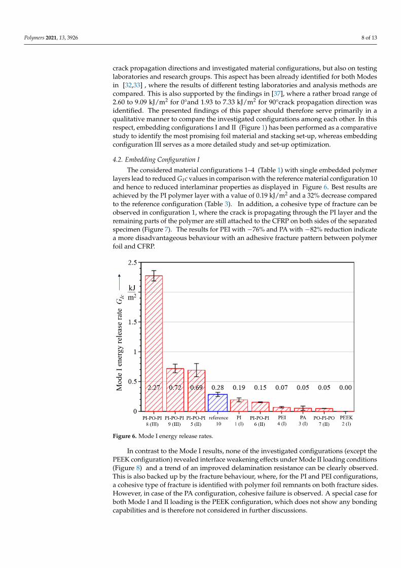
The considered material configurations 1–4 (Table 1) with single embedded polymerlayers lead to reduced GIc values in comparison with the reference material configuration 10and hence to reduced interlaminar properties as displayed in Figure 6. Best results areachieved by the PI polymer layer with a value of 0.19 kJ/m2 and a 32% decrease comparedto the reference configuration (Table 3). In addition, a cohesive type of fracture can beobserved in configuration 1, where the crack is propagating through the PI layer and theremaining parts of the polymer are still attached to the CFRP on both sides of the separatedspecimen (Figure 7). The results for PEI with −76% and PA with −82% reduction indicatea more disadvantageous behaviour with an adhesive fracture pattern between polymerfoil and CFRP.
Figure 6. Mode I energy release rates.
In contrast to the Mode I results, none of the investigated configurations (except thePEEK configuration) revealed interface weakening effects under Mode II loading conditions(Figure 8) and a trend of an improved delamination resistance can be clearly observed.This is also backed up by the fracture behaviour, where, for the PI and PEI configurations,a cohesive type of fracture is identified with polymer foil remnants on both fracture sides.However, in case of the PA configuration, cohesive failure is observed. A special case forboth Mode I and II loading is the PEEK configuration, which does not show any bondingcapabilities and is therefore not considered in further discussions.
Polymers 2021, 13, 3926 9 of 13
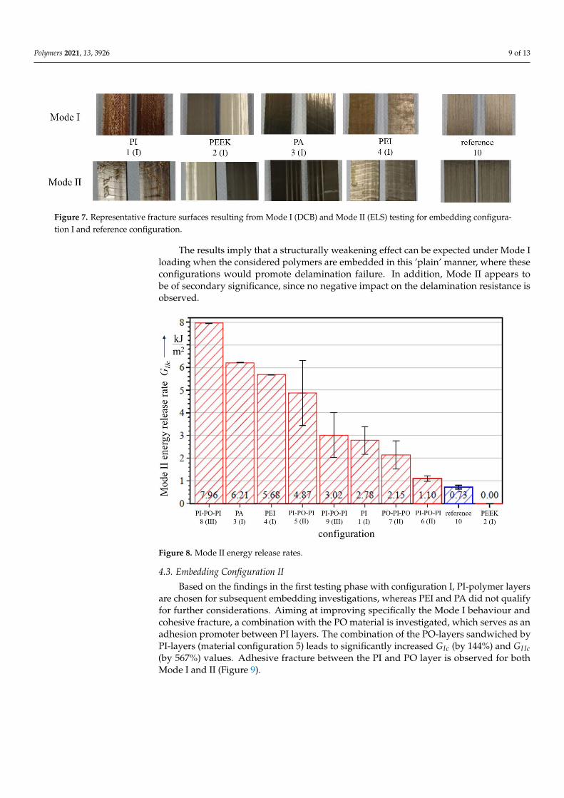
Figure 7. Representative fracture surfaces resulting from Mode I (DCB) and Mode II (ELS) testing for embedding configura-tion I and reference configuration.
The results imply that a structurally weakening effect can be expected under Mode Iloading when the considered polymers are embedded in this ’plain’ manner, where theseconfigurations would promote delamination failure. In addition, Mode II appears tobe of secondary significance, since no negative impact on the delamination resistance isobserved.
Figure 8. Mode II energy release rates.
4.3. Embedding Configuration II
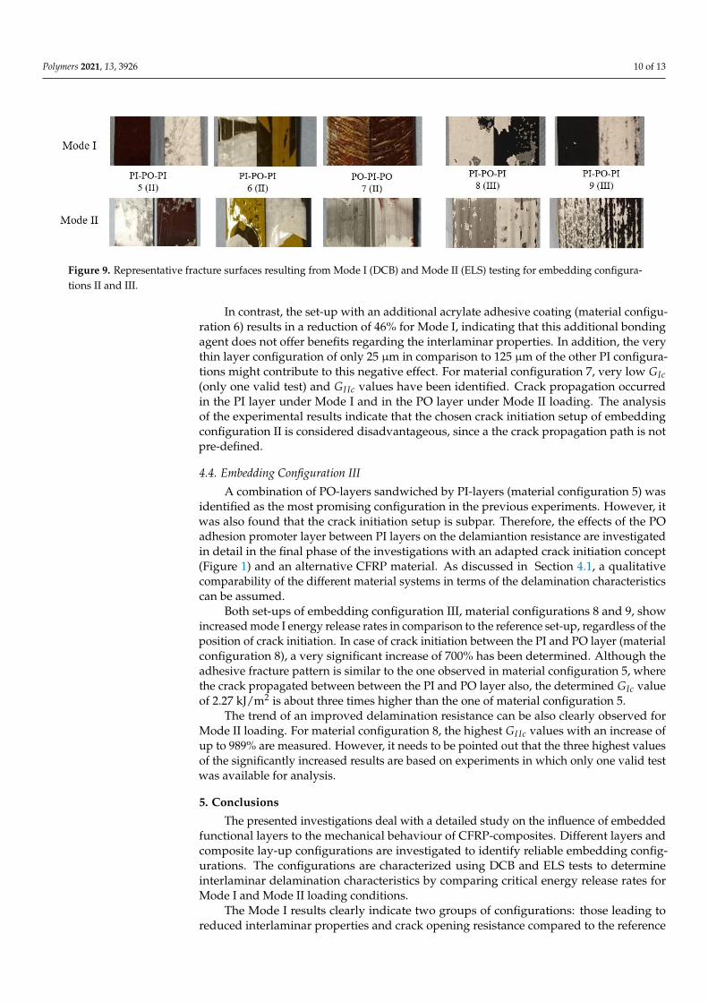
Based on the findings in the first testing phase with configuration I, PI-polymer layersare chosen for subsequent embedding investigations, whereas PEI and PA did not qualifyfor further considerations. Aiming at improving specifically the Mode I behaviour andcohesive fracture, a combination with the PO material is investigated, which serves as anadhesion promoter between PI layers. The combination of the PO-layers sandwiched byPI-layers (material configuration 5) leads to significantly increased GIc (by 144%) and GI Ic(by 567%) values. Adhesive fracture between the PI and PO layer is observed for bothMode I and II (Figure 9).
Polymers 2021, 13, 3926 10 of 13
Figure 9. Representative fracture surfaces resulting from Mode I (DCB) and Mode II (ELS) testing for embedding configura-tions II and III.
In contrast, the set-up with an additional acrylate adhesive coating (material configu-ration 6) results in a reduction of 46% for Mode I, indicating that this additional bondingagent does not offer benefits regarding the interlaminar properties. In addition, the verythin layer configuration of only 25 µm in comparison to 125 µm of the other PI configura-tions might contribute to this negative effect. For material configuration 7, very low GIc(only one valid test) and GI Ic values have been identified. Crack propagation occurredin the PI layer under Mode I and in the PO layer under Mode II loading. The analysisof the experimental results indicate that the chosen crack initiation setup of embeddingconfiguration II is considered disadvantageous, since a the crack propagation path is notpre-defined.
4.4. Embedding Configuration III
A combination of PO-layers sandwiched by PI-layers (material configuration 5) wasidentified as the most promising configuration in the previous experiments. However, itwas also found that the crack initiation setup is subpar. Therefore, the effects of the POadhesion promoter layer between PI layers on the delamiantion resistance are investigatedin detail in the final phase of the investigations with an adapted crack initiation concept(Figure 1) and an alternative CFRP material. As discussed in Section 4.1, a qualitativecomparability of the different material systems in terms of the delamination characteristicscan be assumed.
Both set-ups of embedding configuration III, material configurations 8 and 9, showincreased mode I energy release rates in comparison to the reference set-up, regardless of theposition of crack initiation. In case of crack initiation between the PI and PO layer (materialconfiguration 8), a very significant increase of 700% has been determined. Although theadhesive fracture pattern is similar to the one observed in material configuration 5, wherethe crack propagated between between the PI and PO layer also, the determined GIc valueof 2.27 kJ/m2 is about three times higher than the one of material configuration 5.
The trend of an improved delamination resistance can be also clearly observed forMode II loading. For material configuration 8, the highest GI Ic values with an increase ofup to 989% are measured. However, it needs to be pointed out that the three highest valuesof the significantly increased results are based on experiments in which only one valid testwas available for analysis.
5. Conclusions
The presented investigations deal with a detailed study on the influence of embeddedfunctional layers to the mechanical behaviour of CFRP-composites. Different layers andcomposite lay-up configurations are investigated to identify reliable embedding config-urations. The configurations are characterized using DCB and ELS tests to determineinterlaminar delamination characteristics by comparing critical energy release rates forMode I and Mode II loading conditions.
The Mode I results clearly indicate two groups of configurations: those leading toreduced interlaminar properties and crack opening resistance compared to the reference
Polymers 2021, 13, 3926 11 of 13
configuration and those with improved interlaminar behaviour. In contrast, all investigatedconfigurations lead to increased GI Ic values leading to the conclusion that embeddedpolymer layers foster a high Mode II crack propagation resistance.
Embedded PI layers exhibit the highest combined Mode I and II delamination re-sistance, where the observed cohesive fracture pattern seems to facilitate this effect. Byutilizing PO adhesive promoter films, an enhanced Mode I delamination resistance isachieved. The adhesive capability of the PI layer with the CFRP and the ductility of the POlayer, which hinders crack propagation and bonds the PI layers, proved to be a very goodcombination with respect to Mode I interlaminar crack opening.
Both Mode I and Mode II results lead to the conclusion that the PI-PO-PI config-uration is particularly effective for integrating a polymer film into high-performanceCFRP-composite structures. It even leads to a reduction of delamination proneness. Withthis setup, the PI layers can be functionalized and additional electric elements such assensors or actuators can be positioned between them. The PO layer serves as an internalelectric insulation and also provides spacer and positioning capabilities. Electric insulationof the entire system to CFRP material is achieved by the PI-layers. As an outlook, this con-figuration is suggested to be transferred into further applications as ‘Tailored EmbeddableSensor and Actuator Layer (TEmSAL)’.
Author Contributions: Conceptualization: A.H., E.B.; Data curation: A.H.; Experiments: E.B., A.W.;Funding acquisition: A.H., M.G.; Methodology: A.H., A.W., N.M.; Investigation: A.H., E.B.; Projectadministration: N.M., M.G.; Resources: N.M., M.G.; Supervision: A.H., N.M., M.G.; Visualization:A.H., E.B.; Writing—original draft: A.H., A.W.; Writing—review and editing: A.H., A.W. All authorshave read and agreed to the published version of the manuscript.
Funding: The project leading to this publication has received funding from the European Union’sHorizon 2020, research and innovation programme under Grant No. 636549, project “EXTREME”.
Data Availability Statement: The data presented in this study are available on request from thecorresponding author.
Conflicts of Interest: The authors declare no conflict of interest.
AbbreviationsThe following abbreviations are used in this manuscript:
CFRP Carbon Fibre Reinforced PlasticDCB Double-Cantilever BeamDIC Digital Image CorrelationELS End-Loaded SplitPA PolyamidePEEK Polyether-Ether-KetonePEI PolyetherimidePI PolyimidePO PolyolefinePTFE PolytetraflourethyleneUD Unidirectionally Reinforced
References1. González, C.; Vilatela, J.; Molina-Aldareguía, J.; Lopes, C.; LLorca, J. Structural composites for multifunctional applications:
Current challenges and future trends. Prog. Mater. Sci. 2017, 89, 194–251. [CrossRef]2. Friedrich, K. Polymer composites for tribological applications. Adv. Ind. Eng. Polym. Res. 2018, 1, 3–39. [CrossRef]3. Singh, A.; Afrin, S.; Karim, Z. Green Composites: Versatile Material for Future. In Green Energy and Technology; Springer: Cham,
Switzerland, 2001; Volume 28, pp. 29–44. [CrossRef]4. Modler, N.; Hufenbach, W.; Cherif, C.; Ulbricht, V.; Gude, M.; Maron, B.; Weck, D.; Filippatos, A.; Wiemer, H.; Langkamp, A.
Novel Hybrid Yarn Textile Thermoplastic Composites for Function-Integrating Multi-Material Lightweight Design. Adv. Eng.Mater. 2016, 18, 361–368. [CrossRef]
Polymers 2021, 13, 3926 12 of 13
5. Hufenbach, W.; Böhm, R.; Thieme, M.; Winkler, A.; Mäder, E.; Rausch, J.; Schade, M. Polypropylene/glass fibre 3D-textilereinforced composites for automotive applications. Mater. Des. 2011, 32, 1469–1476. [CrossRef]
6. Rubino, F.; Nisticò, A.; Tucci, F.; Carlone, P. Marine Application of Fiber Reinforced Composites: A Review. J. Mar. Sci. Eng. 2020,8, 26. [CrossRef]
7. Jerkovic, I.; Koncar, V.; Grancaric, A. New Textile Sensors for In Situ Structural Health Monitoring of Textile ReinforcedThermoplastic Composites Based on the Conductive Poly(3,4-ethylenedioxythiophene)-poly(styrenesulfonate) Polymer Complex.Sensors 2017, 17, 2297. [CrossRef]
8. Melnykowycz, M.; Kornmann, X.; Huber, C.; Barbezat, M.; Brunner, A. Performance of integrated active fiber composites in fiberreinforced epoxy laminates. Smart Mater. Struct. 2006, 15, 204. [CrossRef]
9. Winkler, A.; Modler, N.; Drossel, W.G.; Mäder, T.; Körner, C. High-Volume Production-Compatible Technologies for Light Metaland Fiber Composite-Based Components with Integrated Piezoceramic Sensors and Actuators. Adv. Eng. Mater. 2018, 20, 1801001.[CrossRef]
10. Modler, N.; Winkler, A.; Filippatos, A.; Weck, D.; Dannemann, M. Function–integrative Lightweight Engineering—DesignMethods and Applications. Chem. Ing. Tech. 2020, 92, 949–959. [CrossRef]
11. Preumont, A. Vibration Control of Active Structures: An Introduction, 3rd ed.; Solid Mechanics and Its Applications; Springer:Berlin/Heidelberg, Germany, 2011; Volume 179.
12. Elspass, W.; Flemming, M. Aktive Funktionsbauweisen: Eine Einführung in Die Struktronik; Springer: Berlin/Heidelberg, Germany,1998. [CrossRef]
13. Sodano, H.; Park, G.; Inman, D. An investigation into the performance of macro-fiber composites for sensing and structuralvibration applications. Mech. Syst. Signal Process. 2004, 18, 683–697. [CrossRef]
14. Holeczek, K.; Starke, E.; Winkler, A.; Dannemann, M.; Modler, N. Numerical and Experimental Characterization of Fiber-Reinforced Thermoplastic Composite Structures with Embedded Piezoelectric Sensor-Actuator Arrays for Ultrasonic Applications.Appl. Sci. 2016, 6, 55. [CrossRef]
15. de Simone, M.E.; Cuomo, S.; Ciampa, F.; Meo, M.; Nitschke, S.; Hornig, A.; Modler, N. Acoustic emission localization in compositesusing the signal power method and embedded transducers. In Nondestructive Characterization and Monitoring of Advanced Materials,Aerospace, Civil Infrastructure, and Transportation XIII; International Society for Optics and Photonics: Bellingham, WA, USA, 2019;Volume 10971, p. 109711O. [CrossRef]
16. Rocha, H.; Semprimoschnig, C.; Nunes, J. Sensors for process and structural health monitoring of aerospace composites: Areview. Eng. Struct. 2021, 237, 112231. [CrossRef]
17. Tuloup, C.; Harizi, W.; Aboura, Z.; Meyer, Y.; Khellil, K.; Lachat, R. On the manufacturing, integration, and wiring techniques ofin situ piezoelectric devices for the manufacturing and structural health monitoring of polymer–matrix composites: A literaturereview. J. Intell. Mater. Syst. Struct. 2019, 30, 2351–2381. [CrossRef]
18. Lin, M.; Chang, F.K. The manufacture of composite structures with a built-in network of piezoceramics. Compos. Sci. Technol.2002, 62, 919–939. [CrossRef]
19. Yang, S.; Hung, C.; Chen, K. Design and fabrication of a smart layer module in composite laminated structures. Smart Mater.Struct. 2005, 14, 315–320. [CrossRef]
20. Weck, D.; Sauer, S.; Adam, F.; Starke, E.; Böhm, R.; Modler, N. Embedded Sensor Networks for Textile-Reinforced Thermoplastics:Sensor Network Design and Mechanical Composite Performance. Adv. Eng. Mater. 2016, 18, 444–451. [CrossRef]
21. Khudiakova, A.; Brunner, A.; Wolfahrt, M.; Wettemann, T.; Godec, D.; Pinter, G. On the investigation of quasi-static crackresistance of thermoplastic tape layered composites with multiple delaminations: Approaches for quantification. Compos. Part AAppl. Sci. Manuf. 2021, 149, 106484. [CrossRef]
22. Montazerian, H.; Rahide, A.; Milani, A.S.; Hoorfar, M. Integrated Sensors in Advanced Composites: A Critical Review. Crit. Rev.Solid State Mater. Sci. 2019, 44, 1–52. [CrossRef]
23. Chilles, J.; Croxford, A.; Bond, I. Design of an embedded sensor, for improved structural performance. Smart Mater. Struct. 2015,24, 115014. [CrossRef]
24. Winkler, A.; Modler, N.; Weber, T.; Täger, O. Development of a Series Capable Production Process for Fiber-Reinforced Compositeswith Thermoplastic Matrices and Material-Integrated Piezoceramic Modules. Adv. Eng. Mater. 2018, 20, 1800588. [CrossRef]
25. Filippatos, A.; Höhne, R.; Kliem, M.; Gude, M. A composite-appropriate integration method of thick functional components infibre-reinforced plastics. Smart Mater. Struct. 2016, 25, 035026. [CrossRef]
26. Weber, T.; Winkler, A.; Gude, M. Experimental Investigation of the Frequency-Dependent Performance of Thermoplastic-Compatible Piezoceramic Modules (TPM). Adv. Eng. Mater. 2018, 20, 1800568. [CrossRef]
27. Butler, S.; Gurvich, M.; Ghoshal, A.; Welsh, G.; Attridge, P.; Winston, H.; Urban, M.; Bordick, N. Effect of embedded sensors oninterlaminar damage in composite structures. J. Intell. Mater. Syst. Struct. 2011, 22, 1857–1868. [CrossRef]
28. Konka, H.P.; Wahab, M.A.; Lian, K. The effects of embedded piezoelectric fiber composite sensors on the structural integrity ofglass-fiber–epoxy composite laminate. Smart Mater. Struct. 2012, 21, 015016. [CrossRef]
29. ASTM D5528-13. Standard Test Method for Mode I Interlaminar Fracture Toughness of Unidirectional Fiber-Reinforced Polymer MatrixComposites; ASTM International: West Conshehoken, PA, USA, 2013. [CrossRef]
Polymers 2021, 13, 3926 13 of 13
30. ISO 15114:2014. Fibre-Reinforced Plastic Composites—Determination of the Mode II Fracture Resistance for Unidirectionally ReinforcedMaterials Using the Calibrated End-Loaded Split C-ELS) Test and an Effective Crack Length Approach. 2014. Available online: https://www.iso.org/standard/55357.html (accessed on 4 March 2020).
31. Kuhtz, M.; Hornig, A.; Gude, M.; Jäger, H. A method to control delaminations in composites for adjusted energy dissipationcharacteristics. Mater. Des. 2017, 123, 103–111. [CrossRef]
32. Davies, P.; Blackman, B.; Brunner, A. Mode II delamination. In Fracture Mechanics Testing Methods for Polymers, Adhesives andComposites; Moore, D., Pavan, A., Williams, J., Eds.; Elsevier: Amsterdam, The Netherlands, 2001; Volume 28, pp. 307–333.[CrossRef]
33. Brunner, A.; Blackman, B.; Davies, P. Mode I delamination. In Fracture Mechanics Testing Methods for Polymers, Adhesives andComposites; Moore, D., Pavan, A., Williams, J., Eds.; Elsevier: Amsterdam, The Netherlands, 2001; Volume 28, pp. 277–305.[CrossRef]
34. Hansen, P.; Martin, R. DCB, 4ENF and MMB Delamination Characterisation of S2/8552 and IM7/8552; Materials Engineering ResearchLab Report; European Research Office of the US Army: London, UK, 1999.
35. Sebaey, T.; Blanco, N.; Costa, J.; Lopes, C. Characterization of crack propagation in mode I delamination of multidirectional CFRPlaminates. Compos. Sci. Technol. 2012, 72, 1251–1256. [CrossRef]
36. Gordic, M.; Djordjevic, I.; Sekulic, D.; Petrovic, Z.; Stevanovic, M. Delamination Strain Energy Release Rate in Carbon Fiber/EpoxyResin Composites. In Research Trends in Contemporary Materials Science; Trans Tech Publications Ltd.: Freinbach, Switzerland, 2007;Volume 555, pp. 515–519. [CrossRef]
37. Hufenbach, W.; Hornig, A.; Gude, M.; Böhm, R.; Zahneisen, F. Influence of interface waviness on delamination characteristicsand correlation of through-thickness tensile failure with mode I energy release rates in carbon fibre textile composites. Mater. Des.2013, 50, 839–845. [CrossRef]
38. Giannaros, E.; Kotzakolios, A.; Sotiriadis, G.; Kostopoulos, V. A multi-stage material model calibration procedure for enhancingnumerical solution fidelity in the case of impact loading of composites. J. Compos. Mater. 2021, 55, 39–56. [CrossRef]