Morphological and Humidity Sensing Studies of WO3 Mixed with ZnO and TiO2 Powders
Deflections of glulam beams in changing humiditySrpčič, Jelena1, Srpčič, Stane2, Turk, Goran3
ABSTRACT
In the paper long-term tests of small straight glulam beams (0.05 x 0.10 x 1.80 m), loaded with the constant load σmax = 10MPa at the constant temperature 190C ±10C and cyclically changing relative humidity between 65% and 95%, aredescribed. Cycling duration is 1 week, 2 weeks and 4 weeks and continuous measurements of displacements, longitudinaland transversal strains, swelling rates and moisture contents of wood are performed. The tests were completed in January2000 (residual displacements are still being measured), thus only preliminary analysis can be performed. Beams are madefrom two different categories of wood - most of them were made of normal (adult) wood, but some specimens were madefrom young (juvenile) wood. The aim of the research is to obtain comparison between the two categories of wood as wellas to predict the computational model of glulam beams, exposed to constant load and changing humidity.
INTRODUCTION
The increasing deformations due to the long-term load and different moisture conditions have been studied in theSlovenian National Building and Civil Engineering Institute in Ljubljana for quite a long time. Some years ago theexperiments on large straight and curved glulam beams (0.10 x 0.19 x 3.65 m) were carried out, whereas in last two yearsthe long-term tests of smaller straight beams (0.05 x 0.10 x 1.80 m) in different climatic conditions have beeninvestigated. Beams are exposed to one stress level and rapidly changing cyclic relative humidity conditions. Threeduration of relative humidity (RH) cycles were applied to study the delay effect - how the moisture content of quite a bigcross section follows sudden changes of relative humidity and how it influences the deformational behaviour.
MECHANOSORPTIVE EFFECT
It is known that wood, when exposed to moisture content changes, exhibits much greater deformation compared to thewood in constant climate conditions. The simultaneous action of load on the element and changing moisture content (MC)of its material is called mechano-sorptive effect (MSE). The phenomenon was first described by Armstrong & Kingston(1960), then by Armstrong & Christensen (1961) and Hearmon & Paton (1964). In the frequently cited article (Hearmonet.al. 1964), spectacular experimental results were described: deformations of specimens exposed to cyclic RH were at thestress level equal to 3/8 σult approximately 22-times larger then elastic. Many researchers were later interested in thisphenomenon (Grossman, Leicester, Bazant, Hoffmayer & Davidson, Mukudai & Yata, Hunt & Shelton, Ranta Maunus,Mohager & Toratti, Bengtsson). Some of them have carried out experiments on different types of specimens(compression, tension, shear, bending) and different sizes of elements, other have proposed various computationalmodels.
Characteristics of MSEObservations on mechano-sorptive (MS) creep are very interesting and are quite different than at constant relativehumidity conditions: MS creep is not dependent directly on time, but on the moisture content (MC) changes; the creepincreases regardless of the sign of MC change (sorption, desorption). MS deformation is not recovered by removing theload but by MC changes. It is noticed for all loading modes and in all hygroscope materials. Its magnitude dependsmostly on the differences of MC changes and dimensions of the element observed, but also on load direction, loading 1 Senior Research Engineer, Slovenian National Building and Civil Engineering Institute, Dimičeva 12, 1000 Ljubljana,Slovenia2 Associate Professor, University of Ljubljana, Faculty of Civil and Geodetic Engineering, Jamova 2, 1000 Ljubljana,Slovenia3 Assistant Professor, University of Ljubljana, Faculty of Civil and Geodetic Engineering, Jamova 2, 1000 Ljubljana,Slovenia
mode and wood species. Because of different reasons also the wood from young trees (juvenile wood) is often used forstructural elements, the aim of our research was also to determine the influence of the category of wood on MSE.
Influential parametersThe rate of increasing deformations is mostly influenced by the differences in levels of relative humidity to which theelements are exposed. The intensity of increase also depends on the dimensions of elements observed (in smaller crosssections the moisture increases all over the section whereas in bigger sections it increases only in outer layers).Consequently the increased deformations depend also on the direction of loading action (parallel or perpendicular to thewood grain) and on the type of loading (compression, tension, shear, bending). As it can be concluded from – so far a few– investigations, the influential parameters are the species and the age of wood, as well.
DimensionsAs mentioned above MSE depends mostly on the dimensions of elements, exposed to changing RH. Taking into accountonly bending elements we can conclude that very different sizes of specimens were studied. Hearmon & Paton describesthe tests on specimens with cross sections 2x2 mm2 (length 60 mm), where the MSE is explicitly emphasized. Tests, doneby Hoyle, Itani & Eckard, were made on specimens with cross section 89x89 mm2, others by Mohager on specimens10x10x300 mm and 44x94x3900 mm. Leivo had specimens with cross section 45x95 mm, and Toratti with cross sections15x70 mm, 50x100 mm, 75x300 mm and 210x1350 mm. MSE was studied also by M.Houška et al. on specimens withcross section 5x10 mm2, made from three different categories of wood (juvenile, adult and compression wood), so alsothe influence of the category of wood was taken into account. Their work was continued by J. Resnik et al. who studiedglued assemblies (two laminations with dimensions 5x25x140 mm), made of juvenile and compressive coniferous wood.In our work specimens, similar to real structural elements, are analyzed. We chose elements with cross section 50x100mm, loaded with bending load on the 1640 mm span. Two categories of wood were used for specimens: normal (adult)wood, and the so called juvenile (young) wood.
Influence of wood categoryThe increasing need for wood results in the use of small-diameter wood as well as the use of fast growing species, whichhave also a lower price. Because the share of juvenile wood at coniferous species is bigger, the study of differentcategories of softwood is necessary. Juvenile wood is formed in the early stage of growth (15 - 25 years). Juvenile core isoften exposed to cracking, so it is less valued wood. The characteristic properties of this type are short fibers (the shortestin the core) which become longer at the end of juvenile period. Then they reach maximal and stable dimensions,characteristic for adult wood. Juvenile wood of coniferous species has also lower density and consequently lowerstrength. It exhibits greater swelling and shrinkage. Often juvenile wood is combined with compressive wood whichenlarges the nonhomogenity of wood even more. In our investigation the behavior of special beams made exclusivelyfrom juvenile wood was compared to those made from adult wood from which most glulam structures are normallyproduced.
TESTS ON GLULAM BEAMS
Long-term tests of straight glulam beams in different changing climatic conditions were completed in laboratories ofSlovenian National Building and Civil Engineering Institute in Ljubljana in January 2000. All three predicted cycling ofRH: four one-week cycles, three two-week cycles and three one month cycles were carried out and the achieved RH ofthe surrounding was generally following the planned values (65% and 95%, respectively). Tests also include a controlgroup of elements with the same dimensions, not exposed to moisture, and a group of unloaded specimens kept in thesame climatic conditions.

0.547m 0.546m 0.547m
1.80m
0.05m
0.10m
P=1.525 kN
PP/2P/2
Figure 1:Dimensions of specimens and loading arrangement
SpecimensSpecimens were made from European spruce (Abies alba Mill.) and glued with resorcyn-phenol-formaldehide type ofglue. There were 7 laminations in the cross section (thickness of inner laminations was 16 mm and outer 10 mm).Specimens were made by HOJA, Slovenian factory for glulam structures, during the normal production. 36 specimenswere made from normal (adult) wood, and 10 from juvenile wood – mostly from inner parts of trunks, which are usuallyrejected. Final dimensions of all specimens were 50 x 100 x 1800 mm as it is shown in Figure 1.
Modulus of elasticity (MOE)The modulus of elasticity in static bending was measured on six normal and three juvenile specimens at short termbending test. The average values of MOE, calculated from measured displacements, are presented in Table 1:
Table 1: Modulus of elasticity for normal and juvenile woodnormal wood juvenile wood
MOE (MPa) 13.850 9.270
Loading arrangement and stress levelSpecimens are exposed to four point bending load on the span 1640 mm (the distance between forces is 547 mm). Onestress level of 10 MPa was chosen to make better comparison with some previous tests. Demanded loading forces, equalto 1.525 kN (controlled with loading cells at the loading points), were applied. Special balanced system, presented inFigure 2, was constructed to reduce the amount of weight (for each specimen only the load of 2 x 12 N was needed).
Figure 2: Loading arrangement
ScopeFour groups of beams were simultaneously observed, two in cyclic humidity and two in normal RH (16 specimens). Thefirst group of four elements, made from normal wood, and two specimens, made from juvenile wood, was loaded andexposed to cyclic humidity between 65% and 95%. The second group, consisting of two normal and two juvenilespecimens, was kept unloaded in the same climatic conditions for measuring deformations just due to moisture changes.In normal climate (constant relative humidity 65%) three normal and one juvenile specimen were loaded, whereas one
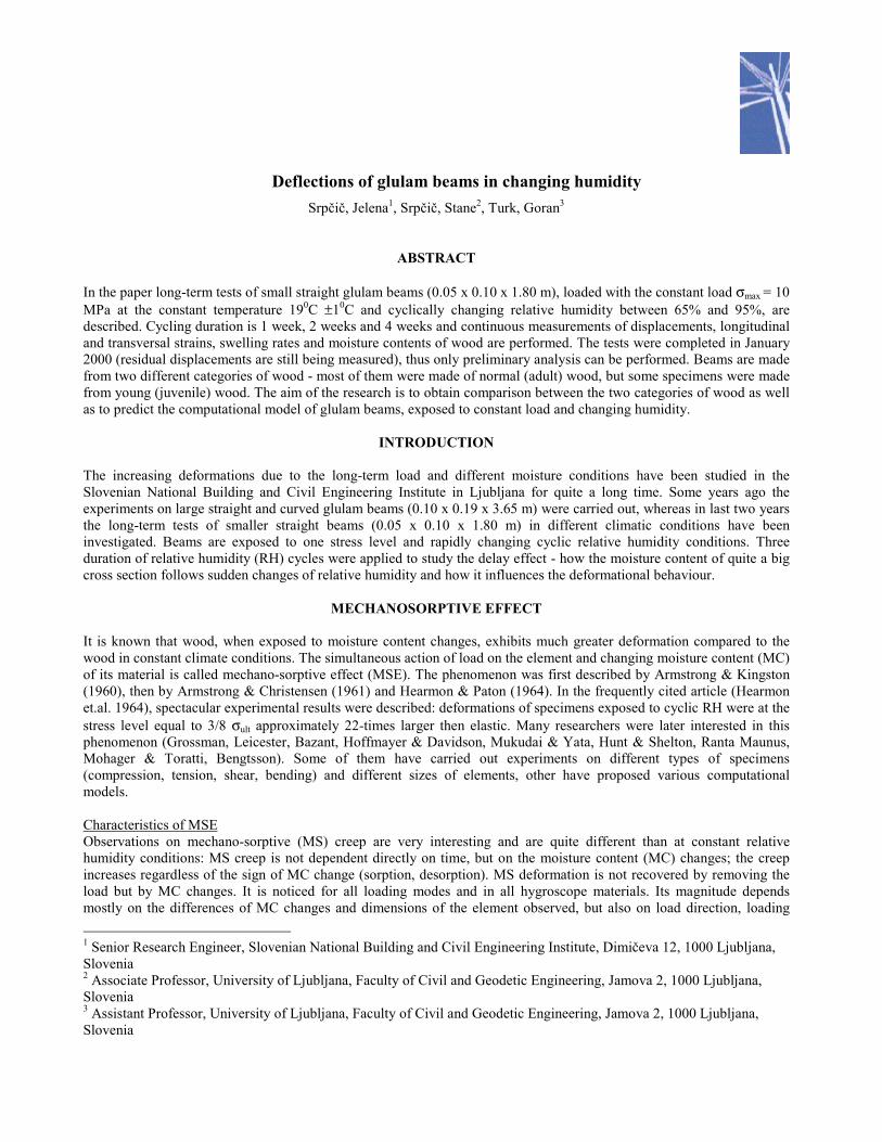
specimen of each kind remained unloaded. All groups were maintained by approximately constant temperature of 19-200.The specimens in the chamber with cyclic RH are shown in Figure 3.
Figure 3: Specimens in the chamber with cyclic relative humidity
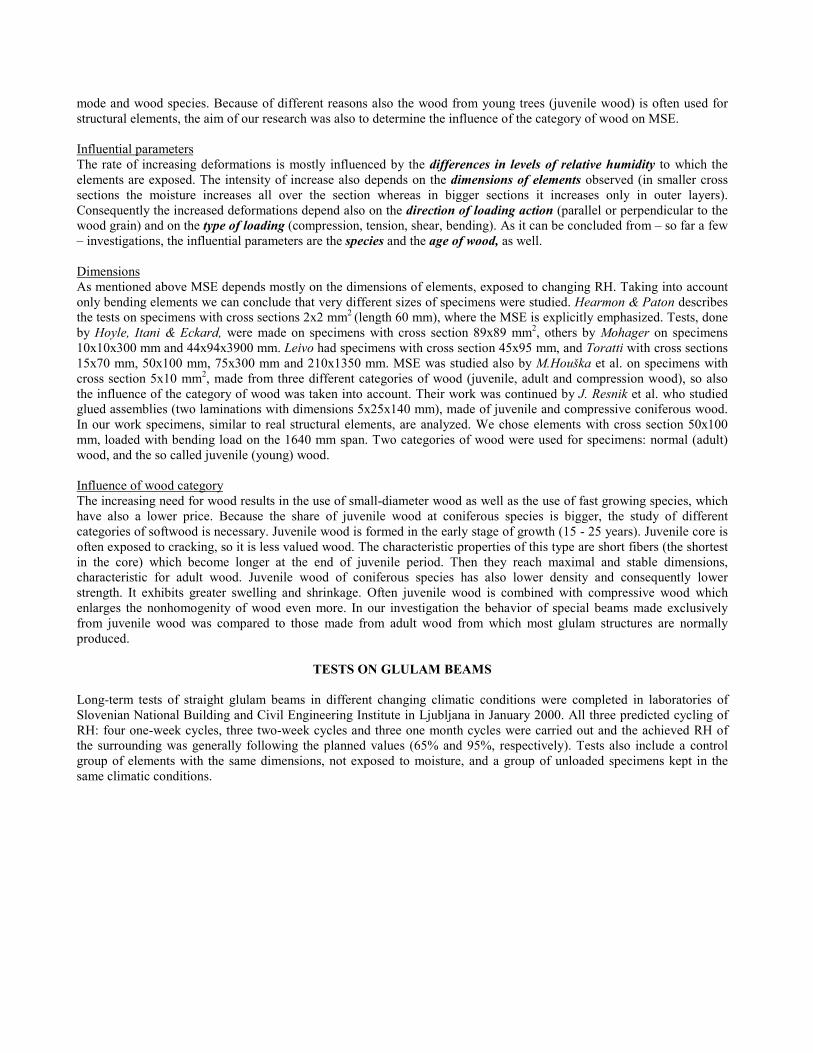
MeasurementsElectronic devices, attached to the specimens for the whole loading period and connected to the computer-controlled dataacquisition system were used during measurements. On the loaded specimens vertical displacements in the axis ofspecimens in the middle of span and on the supports as well as axial elongation were recorded. In the middle crosssections longitudinal strains in the compressive and tensile zone and transversal deformation of cross section due tomoisture changes were measured. On the special specimens, made from the same categories of wood, measurements ofmoisture contents in inner and outer parts of cross sections were carried out.
Figure 4: Measuring devices in the middle cross-section
COMPUTATIONAL MODEL AND TEST RESULTS
Moisture flowThe computational analysis of the mechanical behavior of long-term loaded clear wood or glulam beams fundamentallyconsists of two coupled tasks. However, due to rather slow moisture transfer over the beam, the computational procedurecan be divided into two separate stages. First, the spatial and temporal distribution of the moisture content over the beamhas to be determined in dependency of the anticipated humidity of the airy space surrounding the beam. In the secondstage, the mechanical response of the beam on the time variable mechanical load and humidity has to be analyzed takinginto account the influence of the moisture on the mechanical properties of the material.
In order to determine numerically the spatial distribution of the moisture content over the beam in dependency of time t,generally the 3-D equation of the nonstationary diffusion of moisture has to be solved for the space domain occupied bythe beam. The moisture diffusion inside the domain V can be described by the second Fick's law:
V : ,0tw
xwD
x jij
i
=∂∂−
��
�
�
��
�
�
∂∂
∂∂ (i,j = x,y,z) (1)
where w is the moisture content of wood (kg/m3) and Dij are the components of the diffusion tensor. Since the diffusioncoefficients generally depend on the moisture content, Equation (1) is quasi-linear. The boundary condition on the beamsurface S is:
S : .0qnxwD wiij =−
∂∂ (2)
There qw (kg/m2s) is the water flow through the surface (kg/m2), and ni are components of the unit vector, normal to thesurface.
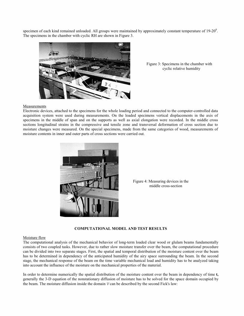
Figure 5: Relative humidity and moisture content of beams (comparison between measured and analytical values)
Assuming the homogenity of the moisture field and the isotropy of diffusion characteristics in the cross-section plane (y,z) Equation (1) is simplified to
,tw
ywD
yxwD
x ∂∂=��
�
����
�
∂∂
∂∂+�
�
���
�
∂∂
∂∂ (3)
while the boundary condition (2) can be expressed asqw = S (wA - wS). (4)
In Equation (4) wA and wS are the equilibrium moisture content (kg/m3) in the surrounding air and the moisture content atthe wood surface, respectively, and S is the surface emissivity coefficient (m/s).
In this work the diffusion problem, described by Equations (3) and (4), was solved using the computer programMOISTURE which is based on the finite element method. The diffusion coefficient D and the surface emissivity S havebeen calibrated experimentally. The test results obtained on small specimens of wood (10 x 5 x 20mm) lead to averagediffusion coefficient D= 4 x 10⁻¹⁰ (m3/s) and to average surface emissivity S= 2 x 10⁻⁶ (m/s). At the first attempt ofnumerical computation of the diffusion constant values of D and S were taken into account.
The program MOISTURE gives the values of moisture contents in discrete points of the finite element scheme of thecross-section in each time-step of the computational procedure. Furthermore the average values of moisture contents wereevaluated for the 1-cm boundary part and for the core of the cross-section. These values are compared with thecorresponding measured values of the moisture contents. The comparison is showed in Figure 5, which indicates, that thediffusion coefficient used may be overestimated. Nevertheless, the moisture contents of discrete points of the cross-section obtained by solving Equation (3) serve as the input data for the second stage of the computation in which themechanical response of loaded beam on cyclic humidity changes has to be determined.
2
4
6
8
1 0
1 2
1 4
1 6
1 8
2 0
0 2 0 4 0 6 0 8 0 1 0 0 1 2 0
T IM E (D A Y S )
MO
ISTU
RE
CO
NTE
NT
(%)
C O M P U T E DM E A S U R E D
9 5 %
6 5 %
P R E D IC T E DM E A S U R E D

DisplacementsWhen analyzing beam elements the basic presumption is that the imaginary longitudinal layers are exposed to uniaxialstress state. For this reason the results of the uniaxial tests can be used directly for the formulation of constitutiverelations. In this way, the physical values of stresses and strains referring to the nondeformed initial state of the beam areused in the analysis.
In order to consider the materially and geometrically nonlinear behaviour of an element, the relation between stress,strain, humidity and time shall be expressed in an incremental form.
dσ = dσ (σ0, ε0, h0, dε, dh, dt). (5)Due to rather small time increments used in the numerical procedure the infinitesimal stress and strain increments can bereplaced by the finite ones. Assuming the addition principle, the increment of the total strain ∆ε belonging to the time step[t0,t1] can be composed as a sum of the elastic ∆εe, normal creep ∆εc, mechano-sorptive creep ∆εms and shrinkage ∆εsstrain increment.
∆ε = ∆εe + ∆εc+ ∆εms + ∆εs (6)The constitutive relations defining the strain increments ∆εe, ∆εc, ∆εms and ∆εs, shall be incorporated into the computerprogram NONWOOD, which was developed on the basis of the finite element method by taking into consideration theBernoulli hypothesis of planar cross-sections. The adopted cinematic equations enable the treatment of largedisplacements and rotations of elements as stiff bodies, as well as moderate strains and rotations in local coordinates ofthe element. The basic equations of the beam finite element are derived from the mixed energy principle, where beside thetransversal displacements and rotations of nodes also the axial force takes place. Thus we avoid the ambiguitiesconcerning the interpolation functions for the longitudinal linear strain and curvature, which, however, take place at "puredeformational method" when analyzing the partial softening of the cross section. At the moment the calibrating of theshrinkage-swelling-, creep- and mechano-sorptive parameters is still in progress and the results are not ready to bepublished yet.
Measured valuesAs mentioned before, the complete investigation has just been completed, so in the article mostly the results ondisplacements will be shown, whereas the deformations in longitudinal direction will be shown at the congress.
Vertical displacementsIn the next figures some characteristic displacements are shown, measured mainly in the middle of span, but alsodisplacements of the supporting points (all measurements were recorded in the neutral axis). Because the four-weekcycling has just been finished, mostly the results of one- and two-week cycling are presented (for comparison maximalvertical displacements also results, obtained by four-week cycling are included). In first figures normalized verticaldisplacements, obtained in the middle point of two normal and two juvenile beams are presented: in Figure 6 for one-week cycling and in Figure 7 for two-week cycling. In both graphs also displacements measured on the specimens, kept inconstant 65% RH are included. In Figure 8 the comparison between vertical displacements of all three cycling - one-week, two-week four-week - are shown.

Figure 6: Vertical displacements of normal and juvenile beams (one-week cycles)
Figure 7: Maximal vertical displacements of normal and juvenile beams (two-week cycles)
Figure 8: Comparison between vertical displacements at three cycling durations
0
0 ,5
1
1 ,5
2
2 ,5
3
0 7 14 21 28 35 42 49 56 63 70
TIM E (D AY S )
NO
RM
ALI
ZED
DIS
PLA
CEM
ENTS
(w /
wel)
95%65%
JU V EN ILE C YC LIC
N O RM AL C Y CL IC
NO RM A L D RY
JU V E NILE D R Y
1 W EE K
0
0 ,5
1
1 ,5
2
2 ,5
3
3 ,5
0 7 1 4 2 1 2 8 3 5 4 2 4 9 5 6 6 3 7 0 7 7 8 4 9 1 9 8 1 0 5 1 1 2 1 1 9 1 2 6 1 3 3 1 4 0 1 4 7 1 5 4
T IM E (D A Y S )
NO
RM
ALI
ZED
DIS
PLA
CEM
ENTS
(w /
w el)
N O R M A L 4 W E E K S
J U V E N IL E 4 W E E K S
J U V E N IL E 2 W E E K S
N O R M A L 2 W E E K S
N O R M A L 1 W E E K
J U V E N IL E 1 W E E K
0
0 ,5
1
1 ,5
2
2 ,5
0 7 14 21 28 35 42 49 56 63 70 77 84 91 98 105 112 119
TIM E (D AY S )
NO
RM
ALI
ZED
DIS
PLA
CEM
ENTS
(w /
wel
)
95%
65%
JU V E N ILE C Y CL IC
NO R M A L C Y C LIC
JU V E N ILE D R Y
NO R M A L D R Y
2 W E E K S
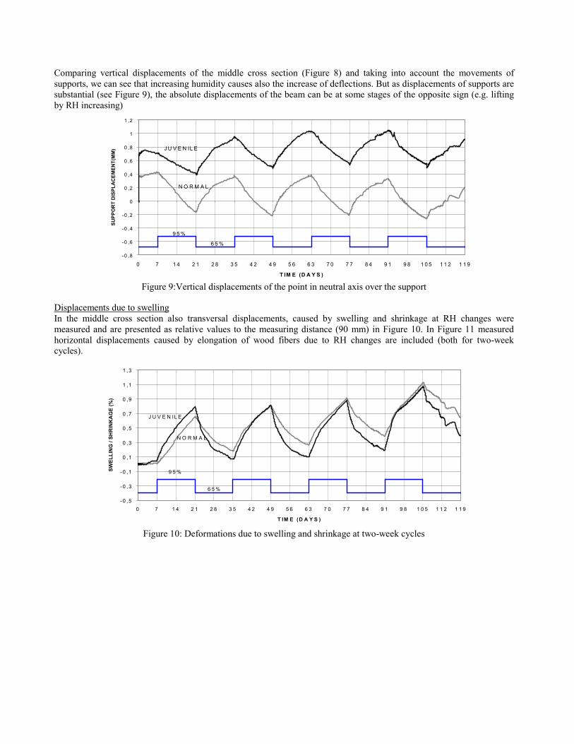
Comparing vertical displacements of the middle cross section (Figure 8) and taking into account the movements ofsupports, we can see that increasing humidity causes also the increase of deflections. But as displacements of supports aresubstantial (see Figure 9), the absolute displacements of the beam can be at some stages of the opposite sign (e.g. liftingby RH increasing)
Figure 9:Vertical displacements of the point in neutral axis over the support
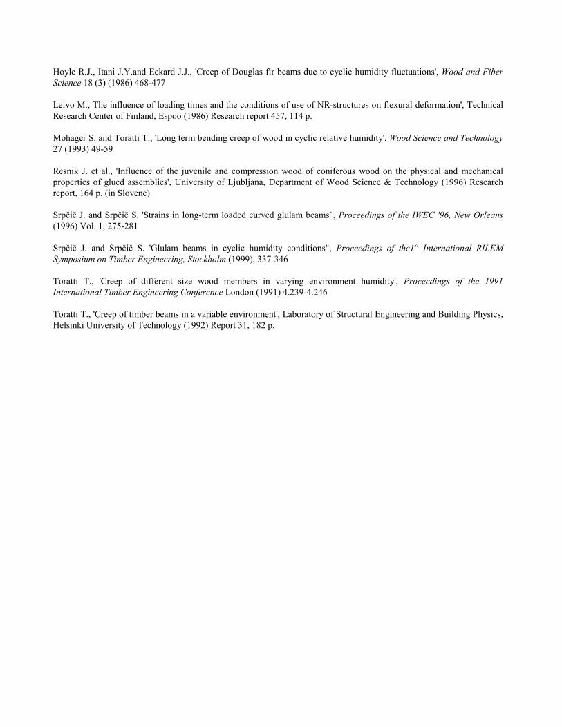
Displacements due to swellingIn the middle cross section also transversal displacements, caused by swelling and shrinkage at RH changes weremeasured and are presented as relative values to the measuring distance (90 mm) in Figure 10. In Figure 11 measuredhorizontal displacements caused by elongation of wood fibers due to RH changes are included (both for two-weekcycles).
Figure 10: Deformations due to swelling and shrinkage at two-week cycles
-0 ,5
-0 ,3
-0 ,1
0 ,1
0 ,3
0 ,5
0 ,7
0 ,9
1 ,1
1 ,3
0 7 1 4 2 1 2 8 3 5 4 2 4 9 5 6 6 3 7 0 7 7 8 4 9 1 9 8 1 0 5 1 1 2 1 1 9
T IM E (D A Y S )
SWEL
LIN
G /
SHR
INK
AG
E (%
)
9 5 %
6 5 %
J U V E N IL E
N O R M A L
-0 ,8
-0 ,6
-0 ,4
-0 ,2
0
0 ,2
0 ,4
0 ,6
0 ,8
1
1 ,2
0 7 1 4 2 1 2 8 3 5 4 2 4 9 5 6 6 3 7 0 7 7 8 4 9 1 9 8 1 0 5 1 1 2 1 1 9
T IM E (D A Y S )
SUPP
OR
T D
ISPL
AC
EMEN
T(M
M) J U V E N IL E
N O R M A L
9 5 %
6 5 %
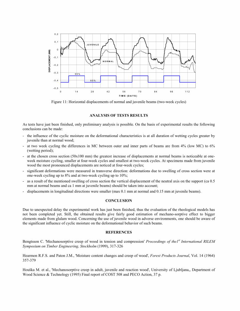
Figure 11: Horizontal displacements of normal and juvenile beams (two-week cycles)
ANALYSIS OF TESTS RESULTS
As tests have just been finished, only preliminary analysis is possible. On the basis of experimental results the followingconclusions can be made:
- the influence of the cyclic moisture on the deformational characteristics is at all duration of wetting cycles greater byjuvenile than at normal wood;
- at two week cycling the differences in MC between outer and inner parts of beams are from 4% (low MC) to 6%(wetting period);
- at the chosen cross section (50x100 mm) the greatest increase of displacements at normal beams is noticeable at one-week moisture cycling, smaller at four-week cycles and smallest at two-week cycles. At specimens made from juvenilewood the most pronounced displacements are noticed at four-week cycles;
- significant deformations were measured in transverse direction: deformations due to swelling of cross section were atone-week cycling up to 8% and at two-week cycling up to 10%;
- as a result of the mentioned swelling of cross section the vertical displacement of the neutral axis on the support (ca 0.5mm at normal beams and ca 1 mm at juvenile beams) should be taken into account;
- displacements in longitudinal directions were smaller (max 0.1 mm at normal and 0.15 mm at juvenile beams).
CONCLUSION
Due to unexpected delay the experimental work has just been finished, thus the evaluation of the rheological models hasnot been completed yet. Still, the obtained results give fairly good estimation of mechano-sorptive effect to biggerelements made from glulam wood. Concerning the use of juvenile wood in adverse environments, one should be aware ofthe significant influence of cyclic moisture on the deformational behavior of such beams.
REFERENCES
Bengtsson C. 'Mechanosorptive creep of wood in tension and compression' Proceedings of the1st International RILEMSymposium on Timber Engineering, Stockholm (1999), 317-326
Hearmon R.F.S. and Paton J.M., 'Moisture content changes and creep of wood', Forest Products Journal, Vol. 14 (1964)357-379
Houška M. et al., 'Mechanosorptive creep in adult, juvenile and reaction wood', University of Ljubljana,, Department ofWood Science & Technology (1995) Final report of COST 508 and PECO Action, 37 p.
- 0 ,5
- 0 ,4
- 0 ,3
- 0 ,2
- 0 ,1
0
0 ,1
0 ,2
0 1 4 2 8 4 2 5 6 7 0 8 4 9 8 1 1 2
T IM E (D A Y S )
DIS
PLA
CEM
ENT
(MM
)
9 5 %
6 5 %
J U V E N IL E
N O R M A L
Hoyle R.J., Itani J.Y.and Eckard J.J., 'Creep of Douglas fir beams due to cyclic humidity fluctuations', Wood and FiberScience 18 (3) (1986) 468-477
Leivo M., The influence of loading times and the conditions of use of NR-structures on flexural deformation', TechnicalResearch Center of Finland, Espoo (1986) Research report 457, 114 p.
Mohager S. and Toratti T., 'Long term bending creep of wood in cyclic relative humidity', Wood Science and Technology27 (1993) 49-59
Resnik J. et al., 'Influence of the juvenile and compression wood of coniferous wood on the physical and mechanicalproperties of glued assemblies', University of Ljubljana, Department of Wood Science & Technology (1996) Researchreport, 164 p. (in Slovene)
Srpčič J. and Srpčič S. 'Strains in long-term loaded curved glulam beams", Proceedings of the IWEC '96, New Orleans(1996) Vol. 1, 275-281
Srpčič J. and Srpčič S. 'Glulam beams in cyclic humidity conditions", Proceedings of the1st International RILEMSymposium on Timber Engineering, Stockholm (1999), 337-346
Toratti T., 'Creep of different size wood members in varying environment humidity', Proceedings of the 1991International Timber Engineering Conference London (1991) 4.239-4.246
Toratti T., 'Creep of timber beams in a variable environment', Laboratory of Structural Engineering and Building Physics,Helsinki University of Technology (1992) Report 31, 182 p.
Copyright © 2022 FDOKUMEN