DATE - Records Collections
37
"•• ° 0 0 0 1 8 7 UNITED STATES ENVIRONMENTAL PROTECTION AGENCY REGION V DATE: October 29, 1987 SUBJECT: Approval of Quality Assurance Project Plan for Remedial Investigation/ ibility Study at the ilational Presto Industries, Inc. Site, Wisconsin asi FRO Quality Assurance Office TO: Norman Niedergang, Chief CERCLA Enforcement Section ATTENTION: Mike Gifford, RPM Our Office is returning a copy of an approved Quality Assurance Project Plan (QAPP) for Remedial Investigation/Feasibility Study at the National Presto Industries, Inc. Site, Eau Claire, Wisconsin, which our Office received on October 28, 1987(QAO #447). The approval of this subject QAPP is provided after our Office has made the following changes: 1. Change made on 3 pages (attached). 2. Replace the SAS for the analysis of low level volatile organics, which is not applicable to laboratory for PRP project, with the 26 pages Standard Operational Procedures (SOP) prepared by Dr. Cheng-Wen Tsai, Chemist, QAO staff (attached). Our Office has provided the special effort to prepare the SOP in order to expedite the approval of this subject QAPP. A copy of the changed page and the SOP has been inserted in the returning QAPP, and an extra copy is attached for your reference and use. Hazleton Laboratory is required to use the Instrumental conditions specified in the SOP; and is also required to clearly document any deviations from the specified instrumental conditions and/or QC requirements, and be part of the data reporting package. The original of signature page is included. Please have the Remedial Project Manager provide final sign off. We have retained a copy of this subject QAPP for our records; however, we would like to receive a copy of the complete signature page when it is available. Attachments cc: K. Chiu, ERRB EPA FORM 132W (REV. 3-76)
-
Upload
khangminh22 -
Category
Documents
-
view
4 -
download
0
Transcript of DATE - Records Collections

"•• ° 0 0 0 1 8 7UNITED STATES ENVIRONMENTAL PROTECTION AGENCY
REGION V
DATE: October 29, 1987
SUBJECT: Approval of Quality Assurance Project Plan for Remedial Investigation/ibility Study at the ilational Presto Industries, Inc. Site, Wisconsinasi
FROQuality Assurance Office
TO: Norman Niedergang, ChiefCERCLA Enforcement Section
ATTENTION: Mike Gifford, RPM
Our Office is returning a copy of an approved Quality Assurance Project Plan(QAPP) for Remedial Investigation/Feasibility Study at the National PrestoIndustries, Inc. Site, Eau Claire, Wisconsin, which our Office received onOctober 28, 1987 (QAO #447). The approval of this subject QAPP is providedafter our Office has made the following changes:
1. Change made on 3 pages (attached).
2. Replace the SAS for the analysis of low level volatile organics,which is not applicable to laboratory for PRP project, withthe 26 pages Standard Operational Procedures (SOP) prepared byDr. Cheng-Wen Tsai, Chemist, QAO staff (attached).
Our Office has provided the special effort to prepare the SOP in order toexpedite the approval of this subject QAPP. A copy of the changed page andthe SOP has been inserted in the returning QAPP, and an extra copy is attachedfor your reference and use. Hazleton Laboratory is required to use theInstrumental conditions specified in the SOP; and is also required to clearlydocument any deviations from the specified instrumental conditions and/or QCrequirements, and be part of the data reporting package.
The original of signature page is included. Please have the Remedial ProjectManager provide final sign off. We have retained a copy of this subject QAPPfor our records; however, we would like to receive a copy of the completesignature page when it is available.
Attachments
cc: K. Chiu, ERRB
EPA FORM 132W (REV. 3-76)

"-S* Lzvi'-onmencai Protection AgencyU* Sample Manafenenc Office. 0. lex S1S» Alexandria, Virginia 22313
i-HOHZ: (703)/S57-2^90 or 173/557-2490
S7ECUU. AHALTTICAlClient Request
lagional Trantui ctal Telephone I^
/
-. RSCC Sapresenrazlvt: Deaclt
w. Telephone Suaber:' (312) 88 -̂1971
~. Data of Kftquasc: ^ .
i.. Site Kaae:
JAN 2 0 1387
prorid* below a a* scrip;! on of your r*qn*st for Special lBaJ.r̂ iex.1 Strricms caderrbe Cotrr»cz liborxrory Jroprxa. la order ro eorc *££ici*&£l?> obciin JaborxzoTv e»p*biliry ie:?ocr r*cracs£, please address rbe fcllovlac co&sidcnslon*. If applleablfc. Ineosslccc or| rrooeoo* isforsazlon siy result is delay in tbe proeesslnj of jour request. ?lease cosslaue; esposM oa addirioajj. sbaczi, or artaci SBppleaeasa,ry iriorsation as needed.
1. Ceaarai descrlpriott cf analytical serrlca reaB«i«Ead:
- for Tolarlles. sesj-rolaslles asl pesticide /?CS vlrh lea?
Dtil=lricm aai Tnmhr* cf work t=its larolvv'd (sp«^f7 wneiber vhole sasales ofnrrlnas; voazbar O7fa=les or inorcaslcx; wn*=b«r aqvaoos or soil a&caaxl vheshtr loct aedisL, or hijb eonca-nrrasins.);
L3. ?cr?o»c of analysis (specify whether Supcrfimd (£eaedlal or En£orcanent),' K?DES, ate,-):

-. Estimated date(s) of collection:
5. Lstiaaced dated) and method of
S. Number of days analysis and data required after laboratory receipt of samples:
* days for analysis. Tiiiaj. report and data due gjr^ti 15^ days of taople receipt.
7. Analytical protocol required (attach copy If other than a protocol currmncly ustd inprogram):
Orwcie Ana.l-'tit ITS WA85-J66A . '
S. 5p*da~ -aehalr.al insrruczioti (If outsiae protocol rtqctraaents, spmeifT1 cospound
1, Z itrrios* to Oriu^is ^3 - AtZJ
I. lL*c-j±r«g log le-^el
ieT oeterrisLaf e^sltl'ytrT l r s : .̂gllT r»socsls*bl« rocctra for^UJJUUULLM qjtat 1° ag ujccsloa lor A3iia aad 1.- ug/~* for VOA*.
fcr gs «Btr=2.i be <*0 fer cacti VQA red A3E
5. Cocrf'*"tTg calibration: B.c= «<»*?T ^''ftrtries «zaa^a.r£ before rrrr4Tirchovlc. o* <2i for all cegpouaos i£. DOCS TOAS aac 13Ka. If *oaa
If rsill oc^. T»rcs 3 •polr
9. iTTa^yrical rtsclzs r*arlr«d Clf fcnowa, s-pcdfT1 for=*t for ca^a «b*cu, QA./QC r«?cr^Cir4 r-cf -Cnstody dor^iaTt-i^lou, *rt.). If not cos?l*£t£. foraar of r»nl£s wiZl be.
co progrw.
All dfcZl-rer>bl«s iaelnded Is the I?3 mrt rtorireg Isslsdiar iasrrcm«zt se-sslrlTlrr
Otbar (us* ad£i=loBal sfa*c£s er ar
11. But of sampling/shipping conracr^
""" Pbont:
Rev. 5.09/15/86
*•"" 3«
I. DATA 8SOUIP.Sg?:TS
tter: Detection Liaii ?Tecision Desiredt^- or Cone.)
Orrmcies ________ See Attaehnenr II Attaehttetir 1
OC
of Audits Lislts* fl Cgac.)
*r«=ics - As ir ITS As ir U3
__ ??OZ"g^? 3T ^T*^ "^ A?^ Sf^'LpTTt«
i Cortaer Cbodc tll^ CT Itegs
(212) 25J-90S7______(312) 886-1572
I.re rum chis reonest to the Sacple hanageaes: Office as aoon as possible to expedite
_processing of jour request for speciti analTtical lerrices. Should TOT: have anj questionsor need any assistance, please call the S*=ple haaageaenc Office.

Attachment I
VOA - Increase sample volus* up to 20 ml to aeet sensitivity Halts.
Initial Calibration: Suf/L, 10ug/L, 20ug/L.Continuing Calibration: 10ug/l except all those conpounds that have a
detection liait greater than 3 -Oug/L which are to be tun at SOug/L.Acrolein and acrylonitrlle can be ran at300ug/L.
Surrogates: As in ITB but at 10 ug/X. with a recovery of 80 - 1201.
Matrix spike: As in ZFB but at 10 ug/L vlth percent recovery 80 - 1201.
SPCC and CCC criteria will not be required. All If i mist be XJ.Q5 .
ASS - Extract Entire 1/2 gallon bottle - rinse cap & bottle - add to sample vol.
Decrease extract volume to help meet sensitivity limits.
T«H*4«i Calibration: 20, 50, aad 100 total nanograms.
, Continuing Calibration: 20 nanograas except for the following:I
Banzoic acid, 2,4 - cisirrophcaol, 2,4^-trlchloropheaol,
all three nitroa&lllne isonert, 4*nirroph«nol, 4,6-ditd.tro-
2-aecbylphenol and pessaealoropheaol vriich are to be
Injected at 50 nanograms.
Surrogates: 20 ppb OT cosponnds with I recoveries as listed in ITB.i . •I AO ppb arU^ coapotmds vicb ' recoveries as listed in ^B,
iUrric SpUca: 20 ppb BK coopounds «l£h » recoveries as listed in XF£.
40 ppb Add compounds with Z recoveries as listed In Ui."
SPCC aad CCC criteria «UJ. not be required.' All ifs most be >C.05. * "".
i Ixcract latlre 1/2 gallon bottle - rinse cap & bottle - add to lasple.
, Pfcsrieide/?CB * Decrease extract volume to help meet sensitivity Uslts.
Calibration: As In ITS using an attenuation vetting
capable of achieving the sensitivity limits la
Attachment IT. 72 hour ran sequence as in
Surrogate: As in EFI.
Matrix Spike: As in UB.
Rev. 3 .09/15/86

— * g,~_o_

APPCNDIX A
STANDARD OPERATIONAL PROCEDURE
FOR
THE ANALYSIS OF VOLATILE QR6ANICS WITH LOW DETECTION LIMITS
AND TRAP GAS CHROMATOGRAPHY/MASS SPECTROMETRY METHOD

eder associates consulting engineers, p.c.
NATIONAL PRESTO INDUSTRIES, INC,EAU CLAIRE, WISCONSIN
TABLE III-l
ANALYTES AND DETECTION LIMITS
I.Volatlles 1n Hater - GC/MS
Low Level VGA Method (Hazleton)
1. Chloromethane2. Bromomethane3. Vinyl Chloride4. Chloroethane5. Methylene Chloride6. Acetone7. Carbon Disulflde8. 1,1-Dichloroethene9. 1,1-Dlchloroethane
10. trans-1,2-D1chloroethene11. Chloroform12. l,2-01chloroethane13. 2-Butanone14. 1.1 J-Trl chloroethane15. Carbon Tetrachlorlde16 Vinyl Acetate17 Bromodlchloromethane18 1.1,2,2-Tetrachloroethane19 1,2-D1chloropropane20 trans-1.3-Dichloropropene21 Trlchloroethene22 Dibromochloromethane23 1,1,2-Trichloroethane24 Benzene25 cls-1,3-D1chloropropene26 2-Chloroethyl Vinyl Ether27 Bromoform28 2-Hexanone29 4-Methyl-2-Pentanone30 Tetrachloroethene31 Toluene32 Chlorobenzene33 Ethyl Benzene34 Styrene35 Total Xylenes
CAS Number
74-74-75-75-75-67-75-75-75-
156-67-
107-78-71-56-108-75-79-78-
10061-79-
124-79-71-
10061-110-75-
591-108-127-108-108-100-100-
-87-3-83-9-01-4-00-3-09-2-64-1-15-0-35-4-35-3-60-5-66-3-06-2-93-3-55-6-23-5-05-4-27-4-34-5-87-5-02-6-01-6-48-1-00-5-43-2-01-5-75-8-25-2-78-610-1-18-4-88-3-90-741-442-5
HazletonDetection Limits
Hater(UQ/L)
.712
.223
.423
.924
.747
.697
.255
.289
.238
.217
.269
.176
.000
.876
.303
.100
.279
.392
.309
.240
.206
.268
.262
.248
.385
.355
.280
.479
.541
.254
.244
.182
.150
.266
.274

Low Level HSL Voa Analyses(CLP SOW Modification)
The following modifications have been made to the analytical protocolspecified 1n the CLP SOW for RAS (organic analyses IFB WA85-J664) to achievelower detection limits for each of the analytes.
o Purge volume: Increase to 25 mL
o Initial calibration: 0.5, 2, 5, 20 and 50yg/l. Percent RSOfor RFs should be less than 40 for each compound.
o Continuing calibration: 10 yg/1; analyze dally before analyzingsamples; percent 0 should be less than 25 for each compound.
o Surrogates: as 1n IFB but at 10 pg/1 with recoveries of BOX to120%.
o Matrix spike: as 1n IFB but at 10 pg/1 with recoveries of 80% to120%.
o Internal standards: as 1n IFB but at 10 vg/1.
o SPCC and CCC: not required; all RFs must be greater than 0.05.
These modifications are Identical to those specified by Region V under SAS forthe analyses of drinking water/residential wells. Using the abovemodification, the method detection limits were determined and are documentedon the attachment.
(03901/lma)

SECTION No. 1QREVISION No. 0DATE October 19. 1987PAGE 22 OF 26
10.1.2.1 If any compound In any sample exceeds thei n i t i a l calibration range, that sample mustbe diluted, the internal standard concentra-tion readjusted, and the sample reanalyzed.Secondary ion quantitation is only allowedwhere there are sample matrix interferenceswith the primary ion. If secondary ionquantitation is performed, document thereasons in the Case Narrative.
10.1.2.2 If the dilution of the sample causes anycompound detected in the first analysis tobe undetected in the second analysis, thenthe results of both analyses shall be re-ported.
10.2 Analysis Procedure
10.2.1 At the beginning of each date that analyses are to bedone, acceptable performance criteria must beachieved by BFB. This performance test must bepassed before any samples, blanks or standards areanalyzed. The performance test should be done underthe following instrument parameters:
Electron energy = 70 V (nomimal)Mass range = 20 to 260 AMUScan Time = To give at least 5 scans per peak but
not to exceed 7 sec. per peak.
10.2.2 Sample purging
10.2.2.1 Set up the purge and trap system
Adjust the purge gas (helium) flow rate to40 ml/min. Set up the purge and trapsystem to purge.
10.2.2.2 F i l l the purging device
Allow the sample to come to ambient temper-ature prior to introducting it into thesyringe.
a) Remove the plunger from a 25 ml syringeand attach a closed syringe valve.
b) Open the sample bottle (or standard)and carefully pour the sample into thesyringe barrel to just short of over-flowing.

SECTION No.REVISION No. Q
1Q
DATE October 19. 1987PAGE 23 OF 26
c) Replace the syringe plunge and compressthe sample.
d) Hold the syringe in upright positionwith the syringe value set on top ofthe syringe. Open the syringe valveand vent any residual air while ad-justing the sample volume to 25 ml.
e) Since this process of taking an aliquotdestroys the validity of the sample forfuture analysis, the analyst shouldf i l l a second syringe at this time toprotect against possible loss of data.
f) Add 10.0 ul of the surrogate spikesolution and 10.0 ul of the internalstandard spiking solution through thevalve bore, then close the valve.
g) Attach the syringe-syringe valve as-sembly to the syringe valve on thepurging device.
h) Open the syringe valves and inject thesample into the purging chamber. Closeboth valves.
10.2.2.3 Purging
a) Purge the sample for 11.0 jKJ.l minutesat ambient temperatufe.
b) After the 11 minutes purge time, attachthe trap to the chromotograph, adjustthe purge and trap system to the desorbmode.
10.2.3 Gas Chromotography/Mass Spectrometry Analysis
a) Setting up GC/MS operating parameters.
Carrier gas flow rate - 40 ml/minInjector temperature - 220°COven temperature - hold at 45°C for 3 minutes thenheated to 220°C at 8°C/min, then held at 200°Cuntil the programmed run time expires.Transfer line temperature - 225°CIon source temperature - 220°CScan range - 40-250 amuElectron energy - 70 V

SECTION No. ___1Q_REVISION No. 0DATE October 19. 19R7PAGE 24 OF 26
b) Introduce the trapped materials to the GC columnby rapidly heating the trap to 180°C while back-flushing the trap with an inert gas between 20and 60 ml/min for 4 minutes. If rapid heating ofthe trap can not be achieved, the GC column mustbe used as a second trap by cooling it to 30°C,or subambient temperature (cryogenic trapping) ifproblem persist, instead of the i n i t i a l programtemperature of 45°C.
c) While the trap is being desorbed into the gaschromatograph, empty the purging chamber usingthe sample introduction syringe. Wash the chamberwith two 25-ml flushes of reagent water.
d) After desorbing the sample from trap for 4 min-utes, recondition the trap by returning the purgeand trap system to the purge mode. Wait 15seconds, then close the syringe valve on thepurging device to begin gas flow through thetrap. The trap temperature should be maintainedat 180°C. After 7 minutes, turn off the trapheater and open the syringe valve to stop the gasflow through the trap. When the trap is cool,the next sample can be analyzed.
e) If the response for any m/z exceeds the workingrange of the system, prepare dilution of thesample with reagent water from the aliquot in thesecond syringe and reanalyze.
10.2.4 Qualitative Identifcatlon
Obtain extracted Ion current profiles(EICPs) for the primary m/z (Table 6) andat least two secondary masses for eachparameter of interest. The followingcriteria must be met:
a) The characteristic masses of each para-meter of interest must maximize in thesame or within one scan of each other.
b) The retention time must fall within+130 seconds of the retention time ofthe authentic compound.
c) The relative peak heights of the threecharacteristic masses in the EICPs must

SECTION No.REVISION No. QDATE October 19. 1987PAGE 25 OF 26
fall within +_20% of the relative inten-sity of these masses in a referencemass spectrum.
10.2.5 Quantitation and Calibration
10.2.5.1 When a parameter has beenidentified, the quantitationof that parameter should bebased on the intergrate abun-dance from the EICPs of theprimary characteristic m/zgiven in Table 6.
10.2.5.2 Use Equation 4 to calulatethe concentration in thesample using the responsefactor (RF) determine inSection 7.2.1.
AsCon. (ug/L) = AIS x RF Eq.6
where As = Area of the charac-teristic m/zforthe parameter orsurrogate standardto be measured.
Ais = Area of the character-istic m/z for theinternal standard.
Cis » Concentration of theinternal standard.
10.2.5.3 Report result in ug/1 withoutcorrection for recoverydata. All QC data obtainedshould be reported with thesample results.

SECTION No. 10REVISION No. 0DATE Qr.tober 19. 1987PAGE 26 OF 26
TABLE 6
CHARACTERISTIC MASSES FOR PURGEABLE ORGANICS
Parameters Primary Secondary
ChloromethaneBromomethaneVinyl chlorideChloroethaneMethylene chlorideTrichlorofluou methane1,1-dichloroethene1.1-dichloroethaneTrans 1,2-dichlormethaneChloroform1.2-dichloroethane1.1.1-trichloroethaneCarbontetrachlorideBromodichloromethane1.2-dichloropropaneTrans-1.3-dichloropropaneTrichloroetheneBenzeneDibromochloromethane1.1.2-trichloroethaneCis-1.3-dichloropropene2-Chloroethyl vinyl etherBromoform1.1.2.2-tetrachloroethaneTetrachloroetheneTolueneChlorobenzeneEthyl benzene1,3-diChlorobenzene1,2-dichlorobenzene1.4-dichlorobenzene
5094626484
101966396839897
117127112
7513078
1279775
106173168164
92112106146146146
5296646649,51,86
10361,9865,83,85,98,10061,988562,64,10099,117,119119,12183,85,12963,65,1147795,97,132
129,208,20683,85,99,132,1347763,65171,175,250,252,254,25683,85,131,133,166129,131,1669111491148,113148,113148,113

APPENDIX A
STANDARD OPERATIONAL PROCEDURE
FOR
THE ANALYSIS OF VOLATILE ORGANICS WITH LOU DETECTION LIMITS
BY PURGE AND TRAP GAS CHROMATOGRAPHY/MASS SPECTROMETRY METHOD
PREPARED BY
CHENG-WEN TSAI, CHEMIST
QUALITY ASSURANCE OFFICE
OCTOBER 19, 1987

TABLE OF CONTENTS
SECTION
1.0
2.0
3.0
4.0
5.0
6.0
7.0
8.0
9.0
10.0
TABLES
1
2
3
4
CONTENTS
SCOPE AND APPLICATION
SUMMARY OF METHOD
INTERFERENCES
SAFETY PRECAUTIONS
APPARATUR AND MATERIALS
REAGENTS
CALIBRATION AND STANDARDIZATION
QUALITY CONTROL
SAMPLE COLLECTION, PRESERVATION AND STORAGE
SAMPLE ANALYSIS
ANALYTES AND DETECTION LIMITS
LISTING OF COMPOUNDS FOUND IN MATRIX SPIKING SOLUTION
BFB KEY IONS AND ABUNDANCE CRITERIA
VOLATILE INTERNAL STANDARDS WITH CORRESPONDING TCL
PAGE
1
2
2
4
5
7
10
16
19
20
3
9
11
13ANALYTES ASSIGNED FOR QUANTITATIONS
SURROGATE SPIKE COMPOUNDS, CONCENTRATIONS ANDRECOVERY LIMITS
CHARACTERISTIC MASSES FOR PURGEABLE ORGANICS
17
26

1SECTION No.REVISION No.DATE October 19. 1987PAGE 1_ OF 26
0
ANALYSIS OF VOLATILE ORGANICS WITH LOW DETECTION LIMITS
BY PURGE AND TRAP GAS CHROMATOGRAPHY/MASS SPECTROMETRY METHOD
(PREPARED BY CHENG-WEN TSAI)
1.0 SCOPE AND APPLICATION
1.1 This method covers the determination of the following 36 purge-able organics.
Parameter
ChloroethaneBenzeneBronodichloromethaneBromoformBromomethaneCarbon tetrachlorideChlorobenzene2-Chloroethyl vinyl etherChloroformChloromethaneDi bromochloromethane1.2-Dichlorobenzene1.3-DiChlorobenzene1.4-DiChlorobenzene1.1-Dichloroethane1.2-Dichloroethene1.1-Dichloroethenecis-l,2-Dichloroethenethrans-1,2-DichloroetheneDichloromethane1.2-Dichloropropanecis-l,3-Dichloropropenetrans-l,3-DichloropropeneEthylbenzeneStyrene1,1,2,3-TetrachloroethaneTetrachloroetheneToluene1.1.1-TriChloroethane1.1.2-TrichloroethaneTrichloroetheneTrichloroflouromethaneVinyl chlorideo--XYlenem-Xylenep-Xylene
CAS Number
75-00-371-43-275-27-475-25-274-83-956-23-5108-90-7100-75-867-66-374-87-3124-48-195-50-1541-73-1106-46-175-34-3107-06-275-35-4156-59-2156-6U-575-09-278-87-510061-01-510061-02-6100-41-4100-42-579-34-5127-18-4108-88-371-55-679-00-579-01-675-69-475-01-495-47-6108-38-3106-42-3
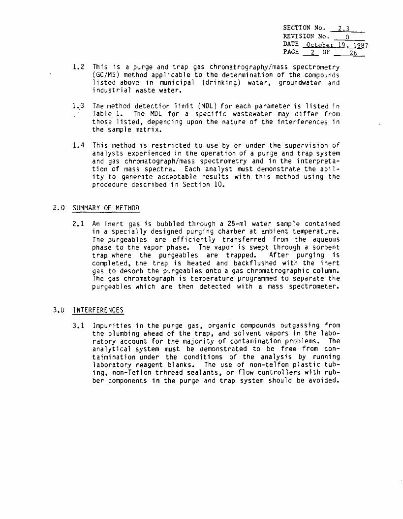
SECTION No. 2.3REVISION No. oDATE October 19. 3Q87PAGE _2__ OF 26
1.2 This is a purge and trap gas chromatrography/mass spectrometry(GC/MSJ method applicable to the determination of the compoundslisted above in municipal (drinking) water, groundwater andindustrial waste water.
1.-3 The method detection limit (MDL) for each parameter is listed inTable 1. The MDL for a specific wastewater may differ fromthose listed, depending upon the nature of the interferences inthe sample matrix.
1.4 This method is restricted to use by or under the supervision ofanalysts experienced in the operation of a purge and trap systemand gas chromatograph/mass spectrometry and in the interpreta-tion of mass spectra. Each 'analyst must demonstrate the abil-ity to generate acceptable results with this method using theprocedure described in Section 10.
2.0 SUMMARY OF METHOD
2.1 An inert gas is bubbled through a 25-ml water sample containedin a specially designed purging chamber at ambient temperature.The purgeables are efficiently transferred from the aqueousphase to the vapor phase. The vapor is swept through a sorbenttrap where the purgeables are trapped. After purging iscompleted, the trap is heated and backflushed with the inertgas to desorb the purgeables onto a gas chromatrographic column.The gas chromatograph is temperature programmed to separate thepurgeables which are then detected with a mass spectrometer.
3.U INTERFERENCES
3.1 Impurities in the purge gas, organic compounds outgassing fromthe plumbing ahead of the trap, and solvent vapors in the labo-ratory account for the majority of contamination problems. Theanalytical system must be demonstrated to be free from con-taimination under the conditions of the analysis by runninglaboratory reagent blanks. The use of non-telfon plastic tub-ing, non-Teflon trhread sealants, or flow controllers with rub-ber components in the purge and trap system should be avoided.

SECTION No. 2REVISION No. QDATE October 19. 1987PAGE 3 OF 9
TABLE 1
ANALYTES AND DETECTION LIMITSby GC/MS Method
PARAMETER
1. Chloromethane2. Bromomethane3. Vinyl Chloride4. Chloroethane5. Mythylene Chloride6. Acetone7. Carbon Disulf ide8. 1,1-Dichloroethene9. 1,1-Dichloroethane
10. trans-l,2-Dichloroethene11. Chloroform12. 1,2-Dichloroethane13. 2-Butanone14. 1,1,1-Trichloroethane15. Carbon Tetrachloride16. Vinyl Acetate17. BromodiChloromethane18. 1,1,2,2-Tetrachloroethane19. 1,2-Dichloropropane20. trans-l,3-Dichloropropene21. Trichloroethene22. Dibromochloromethane23. 1,1,2-Trichloroethane24. Benzene25. cis-l,3-Dichloropropene26. 2-Chloroethyl Vinyl Ether27. Bromoform28. 2-Hexanone29. 4-Methyl-2-Pentanone30. Tetrachloroethene31. Toluene32. Chlorobenzene33. Ethyl Benzene34. Styrene35. Total Xylenes
CAS NUMBER
74-74-75-75-75-67-75-75-75-
156-67-
107-78-71-56-
108-75-79-78-
10061-79-
124-79-71-
10061-110-
75-591-108-127-108-108-100-100-
87-383-901-4•00-309-2•64-115-035-435-360-566-306-293-355-623-505-427-434-587-502-601-648-100-5•43-201-5•75-825-2•78-610-1•18-4•88-3•90-7•41-4•42-5
DETECTION LIMITSWATER(ug/L)
.712
.223
.423
.924
.747
.697
.255
.289
.238
.217
.269
.1761.000.876.303
1.100.279.392.309.240.206.268.262.248.385.355.280.479.541.254.244.182.150.266.274

SECTION No. ___£_REVISION No. 0DATE October 19. 1QS7PAGE 4 OF 26
3.2 Samples can be contaminated by diffusion of volatile organicsthrough the septum seal into the sample during shipment andstorage. A field reagent blank prepared from reagent water andcarried through the sampling and handling protocal can serve asa check on such contamination.
3.3 Contamination by carry-over can occur whenever high level andlow level samples are sequentially analyzed. To reduce carry-over, the purging devide and sample syringe must be rinsed withreagent water between sample analyses. Whenever an unusallyconcentrated sample is encountered, it should be followed by ananalysis of reagent water to check for cross contamination. Itmay be necessary to wash the purging device with a detergentsolution, rinse it with distilled water, and then dry it in a105°C oven between analyses. The trap and other parts of thesystem are also subjected to contamination; therefore, frequentbakeout and purging of the entire system may be required.
4.0 SAFETY PRECAUTIONS
4.1 The toxicity or carcinogenicity of chemicals used in this methodhas not been precisely defined; each chemical should be treatedas a potential health hazard, and exposure to these chemicalsshould be minimized. Each laboratory is responsible for main-taining awareness of OSHA regulations regarding safe handlingof chemicals used in this method. A reference file of materialdata handling sheets should also be made available to all per-sonnel involved in the chemical analysis. Additional refer-ences to laboratory safety are available for the informationof the analyst.
4.2 The following parameters covered by this method have been tenta-tively classified as known or suspected human or mammaliancarcinorgens: benzene, 1,4-dichlorobenzene, hexachlorobutadiene,tetrachloroethene, trichloroethene, carbon tetrachloride, bis-2-chloroisopropyl ether, 1,2-dichloroethane, 1,1,2,2-tetra-chloroethane, 1,1,2-trichloroethane, chloroform, 1,2-dibromo-methane and vinyl chloride. Primary standards of these toxiccompounds should be prepared in a hood. NIOSH/MESA approvedtoxic gas respirator should be worn when the analysts handlehigh concentrations of these toxic compounds.

SECTION No. _REVISION No.DATE October 1Q, IQft?PAGE __s OF __9fi
_Q
5.0 APPARATUS AND MATERIALS
5.1 Sample contai ners
Forty m i l l i l H e r (40-ml) screw cap v i a l s with PTFE-faced s i l i -cone septum seals. Wash vials and seals with detergent, rinsewith tap water, then d i s t i l l e d water, and dry at 105°C, allowto cool in area known to be free of organic vapors.
5.2 Purge and Trap System (Tekmar LSC-2 or equivalent)
5.2.1 Purging Device
The all glass purging device must be capable of accept-ing 25-ml samples with a water column at least 5-cm deep.A glass frit installed at the base of sample chamberallowing purging gas to pass through the water column asfinely divided bubbles with a diameter of 3 cm at theorigi n.
5.2.2 Volatile Trap
The trap must be at least 25 cm long and have an insidediameter of at least 0.105 inches. The trap must con-tain the following amounts of adsorbents: 1/3 of 2,6-diphenylene oxide polymer, 1/3 of silica gel, and 1/3 ofcoconut charcoal. Prior to daily use, the trap isconditioned for 10 minutes at 220°C while backflushingwith an inert gas flow of at least 20 ml/min. The trapeffluent is vented to the room through a charcoal trap.
5.2.3 Desorber
The desorber must be capable of rapidly preheating thetrap to 180°C, then desorbing the trap to the GC columnwhile maintaining the temperature of 180°C.
5.3 GC/MS SYSTEM
5.3.1 Gas chromatograph (Hewlet Parkard 5993 GC or equivalent)
GC must be capable of temperature programming and achiev-ing an i n i t i a l column temperature of 30 - 45°C. Veri-able constrant differential flow controllers capable ofmaintaining constant flow rates throughout the desorbtionand temperature program should be used.

SECTION No.REVISION No.DATEPAGE
019. 1QR7
OF 265.3.2 Gas Chromatography Column
Eight ft. long x 1/8 O.D. glassSP-1000 on Carbopack B (60/80
column, packed with 1%mesh) or equivalent.
5.3.3 Mass Spectrometer (Finnigan 5100 MS or equivalent)
Must be capable of scanning from 20 to 260 amu every 7 sor less, utilizing 70 V (nominal) electron energy in theelectron impact ionization mode, and producing a massspectrum which meet all the criteria in Table 3 when 50ng of 4-bromofluorobenzene (BFB) is injected through theGC inlet.
5.3.4 GC/MS Interface
GC to Ms interface constructed of all glass or glass-lined materials should be used. Glass can be deacti-vated by silanizing with dichlorodimethylsilane.
5.3.5 Data System
A computer system must be interfaced to the mass spectro-meter that allows the continuours acquisition and storageon machine-readable media of all mass spectra obtainedthrough the duration of the chromatographic program.The computer must have the software that allows search-ing any GC/MS data file for specific m/z (masses) andplotting such m/z abundance versus time or scan number.Software must also allow integrating the abundance inany Extracted Ion Current Profile (EICP) between spec-ific time or scan number limits.
5.3.6 Syringe and Syringe Valves
5.3.6.1 Syringes - 5-ml and 25-ml glass hypodermic withluerlock tip (two each).
5.3.6.2 Micro Syringes - 25 and 100 ul.5.3.6.3 Gas syringes - 1.0 and 5.0 ml gas tight, with shut
off valve.
5.3.7 Miscellaneous
5.3.7.1 Standard Storage Containers - 3.7 ml Screw capamber vials.
5.3.7.2 Mininert valuves- screw cap.

SECTION No. ___6_REVISION No. 0DATE October 19. 1987PAGE 7 OF 26
6.0 REAGENTS
6.1 Methanol, demonstrated to be free of analytes (spike 100 ulinto 25-ml reagent water and analyze. Should produce less than0.4 ug/L response).
6.2 Reagent water, producing less than 0.2 ug/L response for thosecompounds that are monitoried. Prepare by boiling distilled ornatural waters for 15 minutes followed by 1-h purge with inertgas w h i l e temperature is held at 90°C or carbon filtered. Storein clean, narrow mounthed crip top PTFE-lined septa bottles.
6.3 Stock standard: Commerical mixed stock solutions are available(Supelco Purgeables A, B, and C) that contain most of thecompounds of interest at a concnetration of 0.2 mg/mL. Stocksolutions must be prepared from neat, as follows for thosecompounds not included in the commerical mixes. (1)
6.3.1 Methanol (24.4 ml) is placed in a 25-mL volumetric flask.Allow flask to stand unstoppered for 10 minutes or untilall alcohol-wetted surfaces have dried and tare.
6.3.2 Using a 100-uL syringe, add 50 mg of assayed referencematerial to the flask. Be sure that the drops falldirectly into the alcohol without contacting the neck ofthe flask. Retare the flask and add 50 mg of the nextcompound. Repeat the process until all compounds havebeen added.
6.3.3 Dilute to volume, and stopper. Mix by inverting flaskseveral times. The resulting solution w i l l contain eachanalyte at a concentration of 2.0 mg/mL.
1) The following compounds must be made from neat: Cis-l,2-Dich1oro-ethene, o-xylene, m-xylene, p-xylene, 1,3-Dichlorobenzene, 1,4-Di-chlorobenzene, 1,2-Dichlorobenzene, Styrene.
6.3.4 Store stock standard solutions in 3 mL v i a l s equippedwith PTFE mininert valve tops at 0°C. All standardsmust be replaced each month.
6.3.5 Secondary Dilution Standards. Using stock standardsprepare secondary dilution standards in methanol. Thesecondary dilution standards are prepared at concentra-tions that can easily be diluted to prepare aqueouscalibration standards that w i l l bracket the workingrange of the method.

SECTION No. 6REVISION No. 0DATE October 19, 1987PAGE fi OF 2fi
6.3.5.1 To prepare secondary dilution standards, place9.0 mL of methanol into a 10 ml volumetricflask.
6.3.5.2 Inject exactly 250 uL of the Supelco Purgeable Astock solution, and 25uL of the stock solutionprepared from neat (above) into the methanol.When prepared as above, the solution willcontain each analyte at a concentration of 5ng/uL.
6.3.5.3 Separate secondary dilution standards mixtureshould be prepared weekly for the gases fromthe Supelco Purgeables C mix.
6.3.5.4 Store secondard dilution standards in 3-mL glassv i a l s equipped with PTFF mininert valve screwtops. Storage conditions and times describedfor stock standard solutions also apply tosecondary dilution standard solutions.
6.4 Sample spiking solution:
Place a 9.5 mL of methanol into a 10 ml volumetric flask, add250 uL of Supelco purgeable A and 250 ul of Supelco Purgeable B.Dilute to volume and mix. The resulting solution w i l l containthe analytes listed in Table 2 at a concentration of 5 ng/ul.Store at 0°C. The sample spiking solution should be discardedafter 1 month.
6.5 Internal surrogate standard:
Prepare from neat bromochloromethane (50 mg) and flourobenzene(125 mg) as in Section 6.3 above. The resulting stock solutionw i l l contain bromochloromethane at 2.0 mg/mL and flourobenzeneat 5.0 mg/mL.
6.5.1 Dilute 25 ul of stock in 25 mL of methanol. The internalsurgogate standard when prepared as above w i l l containbromochloromethane at a concentration of 2 ng/ul andflourobenzene at a concentration of 5 ng/ul.

SECTION No. ___6_REVISION No. 0DATE Qrtnhfir 1Q, 1PAGE
TABLE 2
Listing of Compounds Found In Matrix Spiking Solution
Trans-l,2-Dichloroethylene1,2-Dichlotoethane1,1,1-TrichloroethaneBromodichloromethaneTrans-l,3-DichloropropeneCis-l,3-Dich1oropropeneBenzeneBromoform1,1,2,2-TetrachloroethaneTolueneEthyl BenzeneTrichloroethylene1,1,2-TrichloroethaneDibromochloromethane2-Chloroethyl vinyl etherTetrachloroethyleneChlorobenzeneMethylene ChlorideTrichloroflouromethanel,l-Dichloroethylene1.1-DichloroethaneChloroform1.2-Dichloropropane

SECTION No. ___7_REVISION No. __0DATE October 19.1987PAGE 10 OF 26
7.0 CALIBRATION AND STANDARDIZATION
7.1 Tuning and GC/Ms Mass Calibration
7.1.1 The laboratory must establish that a given GC/MS systemmeet the standard spectral abundance criteria prior toinitiating any on-going data collection. The GC/MSsystem must be hardware tuned to meet the abundancecriteria listed in Table 3 for a maximum of a 50 nginjection of 4-Bromofluorobenzene (BFB). Add 50 ng ofBFB solution to 25 ml of reagent water and analyzealone. BFB should not be analyzed simultaneously withany calibration standards or blanks. This criteria mustbe demonstrated daily or for each twelve-hour timeperiod. If required, .background substraction must bestraight forward and designed only to eliminate columnbleed or instrument background.
7.1.2 BFB criteria must be met before any standards, samplesor blanks are analyzed.
7.1.3 Any action taken which may result in effecting the tun-ing criteria for BFB, the tune must be verified irre-spective of the twelve-hour tuning requests.
7.1.4 The laboratory shall document the GC/MS tuning and masscalibration each time the system is tuned.
7.2 Calibration of GC/MS System
7.2.1 Initial Internal Standard Calibration
7.2.1.1 Prior to the analysis of samples and reguiredblanks, and after tuning criteria have beenmet, the GC/MS system must be initially cali-brated at a minimum of five concentrationsto determine the linearity of response utiliz-i ng TCL compound standards. Once the systemhas been cal i brated, the cal i bration must beverified each twelve (12) hour time period foreach GC/MS system.

SECTION No. 7REVISION No. QDATE October 19,1987PAGE n OF 26
TABLE 3
BFB KEY IONS AND ABUNDANCE CRITERIA
Mass Ion Abundance Criteria
50 15.0 - 40.0 percent of the base peak75 30.0 - 60.0 percent of the base peak95 base peak, 100 percent relative abundance96 5.0 - 9.0 percent of base peak
173 less than 2.0 percent of mass 174174 greater than 50.0 percent of the base peak175 5.0 - 9.0 percent of mass 174176 greater than 95.0 percent but less than 101.0
percent of mass 174177 5.0 - 9.0 percent of mass 176

SECTION No. ____?_REVISION No. 0DATE October 19.1QR7PAGE 12 OF ?.fi
7.2.1.2 Prepare calibration standards to yield the fol-lowing specific concentrations: .5, 2, 5, 20and 50 ug/1. Surrogate and internal standardsshall be used with each of the calibrationstandards.
7.2.1.3 Analyze each calibration standard and tabulatethe area of the primary characteristic ionagainst concentration for each compound includ-ing all required surrogate compounds. Therelative retention time (RRT) of each compoundin each calibration run should agree within0.06 RRT units.
7.2.1.4 Use Table 4 and Equation 1 to calculate therel ati ve response factors (RRF ) for each com-pound at each concentration level.
RRF = —— x —— Eq. 1
where,
Ax = Area of the characteristic ion for thecompound to be measured.
Ajs = Area of tne characteristic ion for the
specific internal standards from Table2.
Cjs » Concentration of the internal standard(ng/uL).
Cx » Concentration of the compound to be measured (ng/uL),
7.2.1.5 Use equation 2 and the relative response factors (RRF) fromthe initial calibration to calibrate the re-lative standard deviation (% RSD) for compoundslabelled as calibration check compoundsin Table 4.
SD%RSD = -«- X 100 Eq. 2
xwhere,
RSD = Relative Standard Deviation

SECTION No. ____REVISION No. __DATE October 19.PAGE 13 OF
01987
26
TABLE 4
VOLATILE INTERNAL STANDARDS WITH CORRESPONINGTCL ANALYTES ASSIGNED FOR QUANTITATION
Bromochloromethane 1,4-Difluorobenzene Chlorobenzene-d5
ChloromethaneBromomethane
*Vinyl ChlorideChloroethaneMethylene ChlorideAcetoneCarbon Disulfide
*l,l-Dichloroethene1.1-Dichloroethane1.2-Dichloroethene (total
*Chloroform1,2-Dichloroethanel,2-Dichloroethane-d4
(surr)
2- Butanone1.1.1-TrichloroethaneCarbon TetrachlorideVinyl AcetateBromodiChloromethane
*l,2-Dichloropropanetrans-l,3-DichloropropaneTrichloroetheneDibromochloromethane1.1.2-TrichloroethaneBenzenecis-l,3-DichloropropeneBromoform
2-Hexanone4-Methyl-2-PentanoneTetrachloroethene1,1,2,2-Tetrachloroethane
*TolueneChlorobenzene
*EthylbenzeneStyreneXylene (total)Bromofluorobenzene
(surr)Toluene-dg (surr)
(surr) = surrogate compoundCalibration check compounds

SECTION No.REVISION No.DATE OctoberPAGE j_4 OF
7. 019. 1987
26
SD = Standard Deviat ion of initial relat iveresponse factors (per compound)
where: SD = . / A. (x^ - x) Eq. 3
N-l
x = mean of i n i t i a l relative response factors(per compound)
The %RSD for each i n d i v i d u a l Calibration CheckCompound must be less than or equal to 30.0percent. This criteria must be met for thei n i t i a l calibration to be valid.
SECTION No. ___7REVISION No. __Q_DATE Orfnher 19. 1QR7PAGE 15 OF 26
7.2.1.6 Syster, Performance Check
A system performance check must be performed toinsure that minimum average relative responsefactors are met before the calibration curve isused. This is done by analyzing five systemperformance check compounds (SPCCs): Chloro-methane, 1,1-dichloroethane, bromoform, 1.1.2.2-tectrachloroethane and chlorobenzene. Theminimum acceptable RRF for these compounds is0.300 (0.250 for bromoform).
7.2.1.7 The initial calibration is valid only afterboth the %RSD for calibration check compoundsand the minimum RRF for SPCC have been met.Only after both these criteria are met cansample analysis begin.
7.3 Continuing Calibration Check
7.3.1 A calibration standard(s) containing all volatile TCLcompounds, including all required surrogates, must beperformed each twelve hours during analysis. {Theconcentration for each TCL compounds in the CCC is 20ug/1). Compare the relative response factor data fromthe standards each twelve hours with the average re-lative response factor from the intital calibration fora specific instrument. A system performance check mustbe made each twelve hours. If the SPCC criteria aremet, a comparison of relative response factors is madefor all compounds.
7.3.2 After the system performance check is met, use Equation4 to caliculate the percent difference (% difference)for all calibration check compounds in Table 4 in orderto check the validity of the initial calibration.
7.3.2.1 Calculate the percent difference using Equation4.
Wj - RRFC% Difference =• ——————— x 100 Eq. 4
RRFj
where
RRFi = average relative response factor frominitial calibration
RRFC = relati ve response factor from currentcalibration check standard

SECTION No.REVISION No.DATE OctoberPAGE i f, OF
80
19. 1Q8726
7.3.2.2 If the percent difference for any compound isgreater than 20%, the laboratory should con-sider this a warning limit. If the percentdifference for each CCC is less than or equalto 25.0%, the initial calibration is assumed tobe valid. If the criteria are not met (>25.0%difference), for any one calibration checkcompound, corrective action MUST be taken.Problems similar to those listed under SPCCcould affect this criteria. If no source ofthe problem can be determined after correctiveaction have been taken, a new initial fivepoint calibration MUST be generated. Thesecriteria MUST be met before sample analysisbegins,
8.U QUALITY CONTROL
8.1 The performance of the entire analytical system can be checkeddai ly using the data collected from the analysis of methodblanks, field blanks, sample matrix spikes, sample matrix spikeduplicates, and calibration check standards.
8.1.1 Method Blank Analysis
A method blank, consists of deionized, distilled labora-tory water, must be analyzed once for each 12-hour timeperiod. The method blank volume must be approximatelyequal to the sample volume being processed. The labor-atory mus_̂ demonstrate the method blank is free ofcontamination.
8.1.2 Surrogate spike analysis
Surrogate standard determination are performed on al 1-samples and blanks. Each sample, matrix spike, matrixspike duplicate, and blanks are spiked with surrogatecompounds to be used. The amount of surrogate standardto be used and the acceptable % recovery limits aretabulated in Table 5.

SECTION No. 8REVISION No. QDATE October 19. 1987PAGE 17 OF 26
TABLE 5
SURROGATE SPIKE COMPOUNDS, CONCENTRATIONS AND RECOVERY LIMITS
Compounds Concentration % Recovery
Toluene-dy
4-Bromoflurorobenzene
l,2-dichtoroethane-d4
50 ug
50 ug
50 ug
88-110
86-115
76-114

SECTION No. ___D_REVISION N o , 0DATE October 19,1987PAGE 18 OF 26
8.1.3 Matrix spike/matrix spike duplicate analysis
8.1.3.1 A matrix spike and matrix spike duplicate must be per-formed for each group of samples of a similar matrix,once0 each Case of field samples received, OR0 each 20 field samples in a Case, OR0 each group of samples of a similar concentration
level (soils only), OR° Each 14 calendar day period during which samples in
a Case were received (said period beginning withthe receipt of the first sample in that SampleDelivery Group), whichever is most frequent.
The concentration of matrix spike should be 2 times ofmethod detection limits (MDL) if the compound is de-tected in the sample, otherwise 5 times of the methoddetection limit.
8.1.3.2 Individual component recoveries of the matrix spike arecalculated using Equation 5.
SSR - SRMatrix Spike Percent Recovery = —————- x 100 Eq.5
SA
where,
SSR = Spike Sample ResultsSR = Sample ResultsSA = Spike Added from spiking mix
8.1.3.3 Relative Percent Difference (RPD)
The contractor is required to calculate the relativepercent difference between the matrix spike and matrixspike duplicate. The relative percent differences(RPD) for each component are calculated using Equation6
D! - D2RPD = ——————— x 100 Eq.6
{D! + o2) /2where,
RPD • Relative Percent DifferenceDI » First Sample ValueD2 • Second Sample Value (duplicate)

SECTION No. __|_REVISION No. _0DATE nrtober 19. 1987PAGE 19 OF 26
9.0 SAMPLE COLLECTION. PRESERVATION. AND STORAGE
9.1 Sample Collection
9.1.1 Replicate trip blanks must be handled along with eachsample set, which is composed of the samples collectedfrom the same general sampling site at approximately thesame time. At the laboratory, fill a minimum of twosample bottles with reagent water, seal, and ship to thesampling site along with empty sample bottles. Wherevera set of samples is shipped and stored, it must beaccompanied by trip blanks.
9.1.2 Field blank sample, which is composed of deionizedlaboratory water, w i l l be collected one per group of 10or fewer samples. Field blank should be prepared in thefield as following: Deionized laboratory water isa 11 owed to be in contract with sampling equipment andthen is poured into the sampling vial. No air bubblesshould be trapped in the field blank sample when thev i a l is sealed.
9.1.3 For samples collected to determine compliance with totaltrinalomethane regulations (40 CFR Part 141.30), add 2.5to 3 mg reducing agent per 40 ml to the empty samplebottles and blanks just prior to shipping to the samplingsite.

SECTION No. 9.10REVISION No. 0DATE October 19.1987PAGE 20 OF 26
9.1.4 Collect all samples in duplicate (triplicate when highlevels requiring screening and d i l u t i o n are suspected).F i l l sample bottles to overflowing. No air bubblesshould pass through the sample as the bottle is filled,or be trapped in the sample when the bottle is sealed.
9.1.5 When sampling from a water tap, open the tap and allow thesystem to flush until the water temperature has stabili-zed (usually about 10 minutes). Adjust the flow toabove 500 mL/minute and collect duplicate samples fromthe flowing stream.
9.1.6 When sampling from an open body of water, f i l l a 1-qtwide-mouth bottle or 1-L breaker with sample from arepresentative area, and carefully f i l l duplicate samplebottles from the 1-qt container.
9.2 Sample Preservation
9.2.1 The samples must be chilled to 4°C on the day of col-lection and maintained at that temperature until analy-sis. Field samples that will not be received at thelaboratory on the day of collection must be packaged forshipment with sufficient ice to ensure that they w i l l beat 4°C on arrival at the laboratory.
9.2.2 Analyze all samples within 14 days of collection. Sam-ples not analyzed within this period must be discardedand replaced.
10.0 SAMPLE ANALYSIS
10.1 Quality Control Requirements
Samples can be analyzed upon successful completion of thei n i t i a l QC activities. When twelve (12) hours have elapsedsince the initial tune was completed, it is necessary toconduct an instrument tune and calibration check analysis.Any major system maintenance, such as a source cleaning ori nstal1 ation of a new column, may necessitate a retune andrecalibration irrespective of the twelve-hour requirement (seeInitial Calibration). Minor maintenance should necessitateonly the calibration verification (Continuing Calibration).
10.1.1 Internal Standards Evaluation - Internal standardresponses and retention times in all samples must beevaluated immediately after or during data acquisition.If the retention time for any internal standard changesby more than 30 seconds, the chromatographic systemmust be inspected for malfunctions, and corrections
SECTION No. 10REVISION No. 0DATE October 19.1987PAGE 21 OF 26
made as required. The extracted ion current profile(EICP) of the internal standards must be monitored andevaluated for each sample, blank, matrix spike, andmatrix spike duplicate. If the extracted ion currentprofile (EICP) area for any internal standard changesby more than a factor of two (-50% to 100%), from thelatest daily (12 hour time period) calibration stand-ard, the mass spectrometric system must be inspectedfor malfunction, and corrections made as appropriate.Breaking off 1 foot of the column (when using capil-1ary column) or cleaning the injector sleeve (whenusing either packed or capillary column) w i l l oftenimprove high end sensitivity for the late elutingcompounds; repositioning or repacking the front end ofthe column w i l l often improve front end column perfor-mance. Poor injection technique can also lead tovariable IS ratios. When corrections are made, re-analysis of samples analyzed while the system wasmalfunctioning is necessary.
10.1.1.1 If after reanalysis, the EICP areas for allinternal standard are inside the acceptablelimits (-50% to +100%), then the problemwith the first analysis is considered to havebeen within the control of the laboratory.Therefore, only submit data from the analy-sis with EICP s within the acceptable limits.This is considered the initial analysis andmust be reported as such on all data deliver-ables.
10.1.1.2 If the reanalysis of the sample does notbolve the problem, i.e., the EICP areas areoutside the acceptable limits for bothanalyses, then submit the EICP data and sam-ple data from both analyses. Distinguishbetween the initial analysis and the reanal-ysis on all data deliverables. Document inthe Case Narrative all inspection and cor-rective actions taken.
10.1.2 Each analytical run must also be checked for satura-tion. The level at which an individual compound willsaturate the detection system is a funtion of theoverall system sensitivity and the mass spectralcharacteristics of that compound. The initial methodcalibration requires that the system should not besaturated for high response compounds at 200 ug/L forVOA TCL compounds.