Data sheet for power supply CP-C.1 24/5.0 - ABB
18
2CDC 271 009 V0017 The CP-C.1 power supplies are ABB’s high-performance and most advanced range. With excellent efficiency, high reli- ability and innovative functionality they are prepared for the most demanding industrial applications. These power supplies have a 150 % integrated power reserve and operate at an efficiency of up to 93 %. They are equipped with over- heat protection and active power factor correction. Combined with a broad AC and DC input range and extensive worldwide approvals the CP-C.1 power supplies are the preferred choice for professional DC applications. Giving the power to control. — Ordering details - CP-C.1 Input voltage range Rated output voltage / current PCBA Type Order code Weight (1 pc.) kg (lb) 85-264 V AC, 90-300 V DC 24 V DC / 5 A uncoated CP-C.1 24/5.0 1SVR360563R1001 0.74 (1.63) coated CP-C.1 24/5.0-C 1SVR360563R2001 0.74 (1.63) uncoated CP-C.1 24/5.0-L 1SVR361563R1001 0.74 (1.63) — Related products Description Redundancy unit PCBA Type Order code Weight (1 pc.) kg (lb) 2 inputs each up to 20 A and 1 output up to 40 A ≤ 56 V and ≤ 40 A uncoated CP-C.1-A-RU 1SVR360060R1001 1.04 (2.29) coated CP-C.1-A-RU-C 1SVR360060R2001 1.04 (2.29) uncoated CP-C.1-A-RU-L 1SVR361060R1001 1.04 (2.29) Characteristics • Rated output voltage 24 V DC • Power reserve design delivers up to 150 % at T a ≤ 40 °C • Output voltage adjustable via front-face rotary poten- tiometer “OUTPUT Adjust”, 22.5-28.5 V • Input voltage range 85-264 V AC, 90-300 V DC • High efficiency • Low power dissipation and low heating • Free convection cooling (no forced cooling) • Devices with coated PCBAs for harsh environments and with extended temperature range • ATEX/IECEx approvals for hazardous locations available • Open-circuit, overload and short-circuit stable • Integrated input fuse • DC OK - signaling output “13-14” (relay), power reserve signaling output “I > I R (transistor) • Redundancy unit CP-C.1-A-RU offering true redundancy, available as accessory • Various certifications and approvals (see overview, document no. 2CDC114098D0201) Power supply CP-C.1 24/5.0 High-performance primary switch mode power supply — DATA SHEET
-
Upload
khangminh22 -
Category
Documents
-
view
2 -
download
0
Transcript of Data sheet for power supply CP-C.1 24/5.0 - ABB

2CD
C 2
71 0
09
V0
017
The CP-C.1 power supplies are ABB’s high-performance and most advanced range. With excellent efficiency, high reli-ability and innovative functionality they are prepared for the most demanding industrial applications. These power supplies have a 150 % integrated power reserve and operate at an efficiency of up to 93 %. They are equipped with over-heat protection and active power factor correction.
Combined with a broad AC and DC input range and extensive worldwide approvals the CP-C.1 power supplies are the preferred choice for professional DC applications.
Giving the power to control.
— Ordering details - CP-C.1
Input voltage range Rated output voltage / current PCBA Type Order code Weight (1 pc.)
kg (lb)
85-264 V AC, 90-300 V DC 24 V DC / 5 A
uncoated CP-C.1 24/5.0 1SVR360563R1001 0.74 (1.63)
coated CP-C.1 24/5.0-C 1SVR360563R2001 0.74 (1.63)
uncoated CP-C.1 24/5.0-L 1SVR361563R1001 0.74 (1.63)
— Related products
Description Redundancy unit PCBA Type Order code Weight (1 pc.)kg (lb)
2 inputs each up to 20 A and 1 output up to 40 A ≤ 56 V and ≤ 40 A
uncoated CP-C.1-A-RU 1SVR360060R1001 1.04 (2.29)
coated CP-C.1-A-RU-C 1SVR360060R2001 1.04 (2.29)
uncoated CP-C.1-A-RU-L 1SVR361060R1001 1.04 (2.29)
Characteristics• Rated output voltage 24 V DC• Power reserve design delivers up to 150 % at Ta ≤ 40 °C• Output voltage adjustable via front-face rotary poten-
tiometer “OUTPUT Adjust”, 22.5-28.5 V• Input voltage range 85-264 V AC, 90-300 V DC• High efficiency• Low power dissipation and low heating• Free convection cooling (no forced cooling)
• Devices with coated PCBAs for harsh environments and with extended temperature range
• ATEX/IECEx approvals for hazardous locations available• Open-circuit, overload and short-circuit stable• Integrated input fuse• DC OK - signaling output “13-14” (relay), power reserve
signaling output “I > IR (transistor)• Redundancy unit CP-C.1-A-RU offering true redundancy,
available as accessory• Various certifications and approvals
(see overview, document no. 2CDC114098D0201)
Power supply CP-C.1 24/5.0
High-performance primary switch mode power supply
—DATA S H EE T
2 P OWE R S U PPLY CP- C . 1 24/5.0 H I G H - PER FO R M A NCE PR I M A RY S W ITCH M O DE P OW ER SU PPLY
ApplicationThe primary switch mode power supply CP-C.1 has a wide AC or DC input voltage range. Furthermore the CP-C.1 is equipped with capacitors that ensure a hold-up time of at least 50 ms. This enables worldwide usage and permits safe operation in fluctuating networks and battery-powered applications.
The CP-C.1 power supplies with the robust metallic housing and the reliable construction are suitable for applications in industrial environments. The CP-C.1-C units, having coated PCBAs, enable usage in even harsh industrial environments.
The power reserve of up to 150 % enables trouble-free starting of heavy loads eliminating the need of usage of an oversized power supply.
Power reserveThe primary switch mode power supply CP-C.1 is equipped with a power reserve functionality to handle the start-up of particulary heavy loads (e.g. of a capacitive load or a motor). To ensure that heavy loads are started up, the CP-C.1 delivers additionally up to 150 % of the rated output current to secure the operation of the application. This status is displayed by the yellow LED labelled POWER RESERVE I > IR.
Signaling outputFor the communication of the status of the power supply the CP-C.1 is equipped with a relay output to signal output OK as well as a transistor output to indicate when the power reserve is active. These signals can be used for communication to a higher level control system e.g. a PLC.
Adjustable output voltageThe CP-C range power supplies feature a continuously adjustable output voltage of 22.5 to 28.5 V DC. Thus they can be optimally adapted to the application, e.g. compensating the voltage drop caused by a long line length.
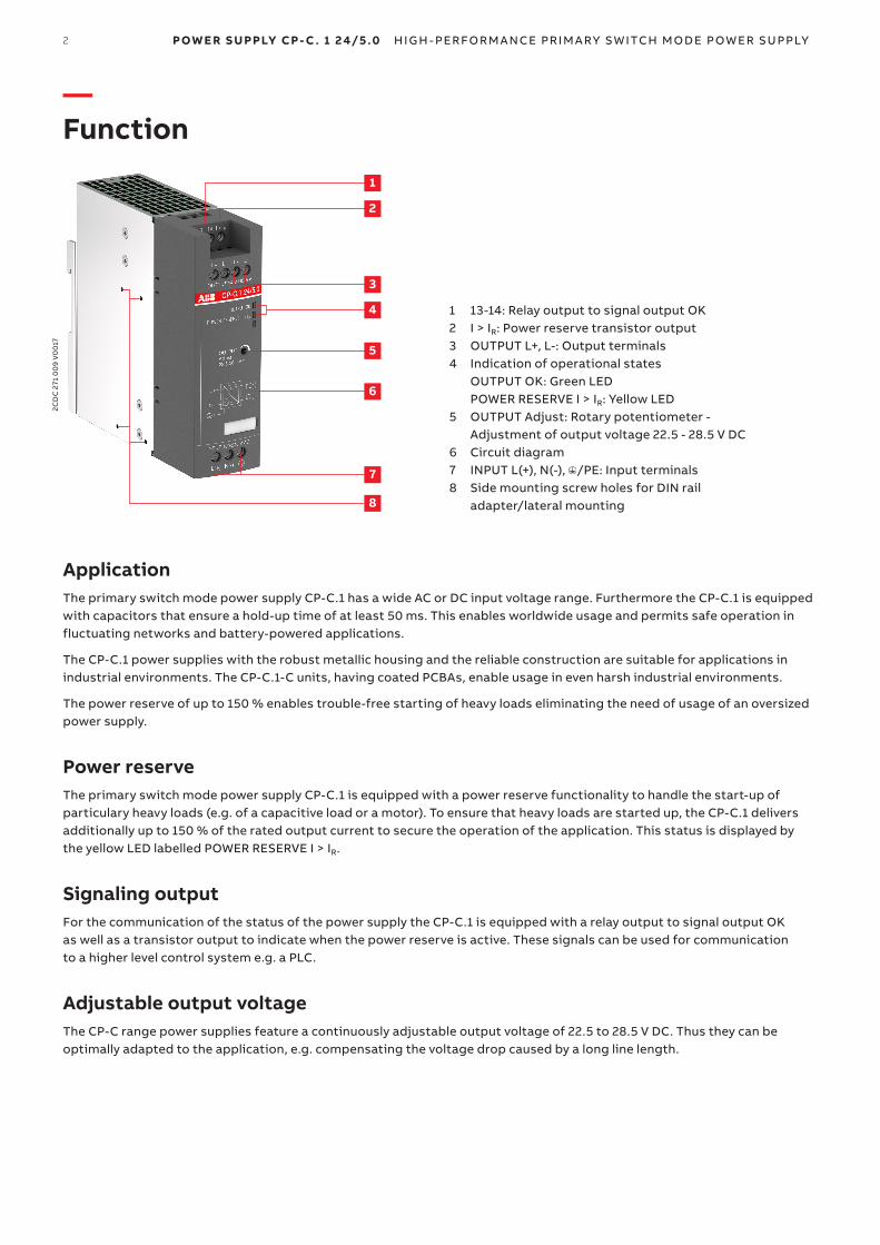
— Function
1
2
4
5
6
3
7
8
1 13-14: Relay output to signal output OK 2 I > IR: Power reserve transistor output 3 OUTPUT L+, L-: Output terminals 4 Indication of operational states OUTPUT OK: Green LED POWER RESERVE I > IR: Yellow LED 5 OUTPUT Adjust: Rotary potentiometer - Adjustment of output voltage 22.5 - 28.5 V DC 6 Circuit diagram 7 INPUT L(+), N(-), /PE: Input terminals 8 Side mounting screw holes for DIN rail adapter/lateral mounting
2CD
C 2
71 0
09
V0
017
P OWE R S U PPLY CP- C . 1 24/5.0 H I G H - PER FO R M A NCE PR I M A RY S W ITCH M O DE P OW ER SU PPLY3
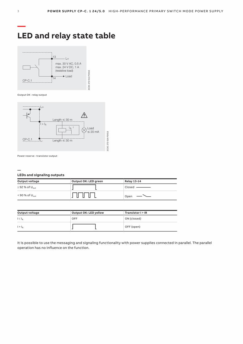
— LED and relay state table
max. 30 V AC, 0.5 Amax. 24 V DC, 1 A(resistive load)
14
13 L+
Load
CP-C.1
2CD
C 2
72 0
13 F
00
15
Output OK - relay output
I > IR
L+
L-
Load � 20 mA
Length � 30 mCP-C.1
Length � 30 m
2CD
C 2
72 0
14 F
00
15
Power reserve - transistor output
— LEDs and signaling outputs
Output voltage Output OK: LED green Relay 13-14
≥ 92 % of Uout V Closed
< 90 % of Uout Z Open
Output voltage Output OK: LED yellow Transistor I > IR
I ≤ IR OFF ON (closed)
I > IR V OFF (open)
It is possible to use the messaging and signaling functionality with power supplies connected in parallel. The parallel operation has no influence on the function.

4 P OWE R S U PPLY CP- C . 1 24/5.0 H I G H - PER FO R M A NCE PR I M A RY S W ITCH M O DE P OW ER SU PPLY
— Operating mode
Parallel operationThere are two main reasons for a parallel connection of power supplies:
• Increase of power• RedundancyUp to 5 devices of the same type can be connected in parallel. For safe and reliable operation it is important to follow the recommendations given in the following section.
Parallel connection of power supplies for increased powerIf the current required by the load is higher than a single power supply can deliver, for example after the expansion of an existing installation, an increase of the output power can be obtained by connecting power supplies in parallel. The following prerequisites have to be fulfilled when connecting power supplies in parallel for the purpose of increased power:
• The paralleled devices must be of the identical type.• Repeated voltage drops on the supply lines or at the terminals would lead to unbalanced load at the common connection
point. To prevent this, you have to observe the following when connecting the power supply units:
- Identical lengths of the load supply lines. - Identical conductor cross sections of the load supply lines. - Terminal screws have to be fastened with the same torque to guarantee equal contact resistances. - The output voltages of the power supplies must not differ by more than 50 mV. Otherwise, safe operation is not possible.
-+ -+ -+ -+ -+ -+
+ -
1. CP-C.1 2. CP-C.1 3. CP-C.1
load
2CD
C 2
72 0
02
F00
15
Correct wiring for increased power
2CD
C 2
72 0
01
F00
15
Installation for increased power
-+
-+ -+ -+ -+ -+ -+
3. CP-C.12. CP-C.11. CP-C.1
load
2CD
C 2
72 0
03
F00
15
Incorrect wiring for increased power
Important The devices must not be connected directly to each other! This could lead to an overload of the terminals since ! the terminals are dimensioned for the maximum output current of a single power supply only. Always use a common connection point!
P OWE R S U PPLY CP- C . 1 24/5.0 H I G H - PER FO R M A NCE PR I M A RY S W ITCH M O DE P OW ER SU PPLY5
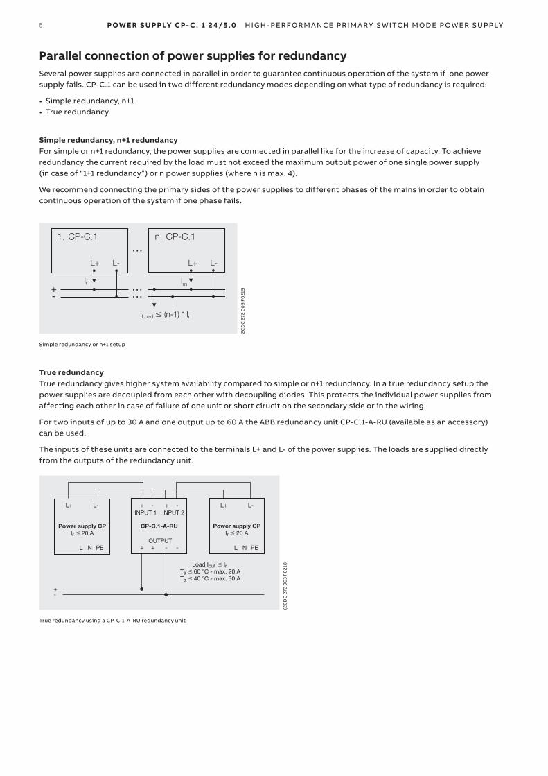
Parallel connection of power supplies for redundancySeveral power supplies are connected in parallel in order to guarantee continuous operation of the system if one power supply fails. CP-C.1 can be used in two different redundancy modes depending on what type of redundancy is required:
• Simple redundancy, n+1 • True redundancy
Simple redundancy, n+1 redundancyFor simple or n+1 redundancy, the power supplies are connected in parallel like for the increase of capacity. To achieve redundancy the current required by the load must not exceed the maximum output power of one single power supply (in case of “1+1 redundancy”) or n power supplies (where n is max. 4).
We recommend connecting the primary sides of the power supplies to different phases of the mains in order to obtain continuous operation of the system if one phase fails.
CP-C.11. n. CP-C.1
L+ L+L- L-
Ir1 Irn
ILoad � (n-1) * Ir
2CD
C 2
72 0
05
F021
5
Simple redundancy or n+1 setup
True redundancyTrue redundancy gives higher system availability compared to simple or n+1 redundancy. In a true redundancy setup the power supplies are decoupled from each other with decoupling diodes. This protects the individual power supplies from affecting each other in case of failure of one unit or short cirucit on the secondary side or in the wiring.
For two inputs of up to 30 A and one output up to 60 A the ABB redundancy unit CP-C.1-A-RU (available as an accessory) can be used.
The inputs of these units are connected to the terminals L+ and L- of the power supplies. The loads are supplied directly from the outputs of the redundancy unit.
Power supply CPIr � 20 A
Power supply CPIr � 20 A
L+ L+L- L-
CP-C.1-A-RU
INPUT 1 INPUT 2+ + --
OUTPUT+ -+ -L N PE L N PE
+-
Load Iout � Ir Ta � 60 °C - max. 20 ATa � 40 °C - max. 30 A
(2C
DC
272
00
3 F0
218
True redundancy using a CP-C.1-A-RU redundancy unit
6 P OWE R S U PPLY CP- C . 1 24/5.0 H I G H - PER FO R M A NCE PR I M A RY S W ITCH M O DE P OW ER SU PPLY
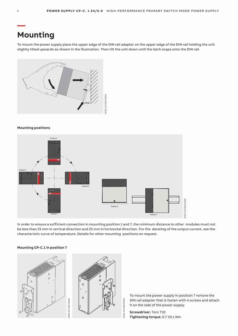
— MountingTo mount the power supply place the upper edge of the DIN rail adapter on the upper edge of the DIN rail holding the unit slightly tilted upwards as shown in the illustration. Then tilt the unit down until the latch snaps onto the DIN rail.
2CD
C 2
73 0
02
F00
15
Mounting positions
Position 5
Position 7
Position 2
Position 4
Position 3
Position 1
2CD
C 2
72 0
01
F00
16
In order to ensure a sufficient convection in mounting position 1 and 7, the minimum distance to other modules must not be less than 25 mm in vertical direction and 25 mm in horizontal direction. For the derating of the output current, see the characteristic curve of temperature. Details for other mounting positions on request.
Mounting CP-C.1 in position 7
To mount the power supply in position 7 remove the DIN rail adapter that is fasten with 4 screws and attach it on the side of the power supply.
Screwdriver: Torx T10 2C
DC
273
00
5 F0
015
2CD
C 2
73 0
08
F00
15
Tightening torque: 0.7 ±0.1 Nm
P OWE R S U PPLY CP- C . 1 24/5.0 H I G H - PER FO R M A NCE PR I M A RY S W ITCH M O DE P OW ER SU PPLY7
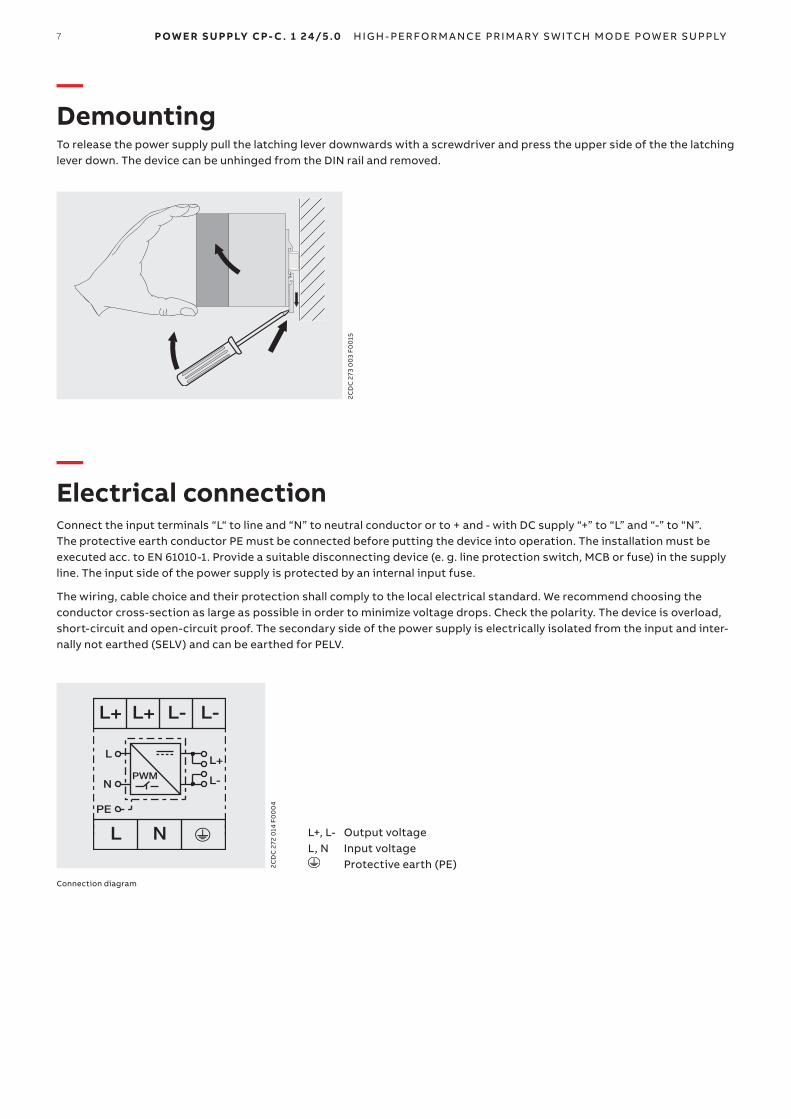
— DemountingTo release the power supply pull the latching lever downwards with a screwdriver and press the upper side of the the latching lever down. The device can be unhinged from the DIN rail and removed.
2CD
C 2
73 0
03
F00
15
— Electrical connectionConnect the input terminals “L“ to line and “N” to neutral conductor or to + and - with DC supply “+” to “L” and “-” to “N”. The protective earth conductor PE must be connected before putting the device into operation. The installation must be executed acc. to EN 61010-1. Provide a suitable disconnecting device (e. g. line protection switch, MCB or fuse) in the supply line. The input side of the power supply is protected by an internal input fuse.
The wiring, cable choice and their protection shall comply to the local electrical standard. We recommend choosing the conductor cross-section as large as possible in order to minimize voltage drops. Check the polarity. The device is overload, short-circuit and open-circuit proof. The secondary side of the power supply is electrically isolated from the input and inter-nally not earthed (SELV) and can be earthed for PELV.
L+, L- Output voltage L, N Input voltage
L+ L+ L-
L N o
L-
L-
L+L
N
PE
PWM
2CD
C 2
72 0
14 F
00
04
Protective earth (PE)
Connection diagram
8 P OWE R S U PPLY CP- C . 1 24/5.0 H I G H - PER FO R M A NCE PR I M A RY S W ITCH M O DE P OW ER SU PPLY
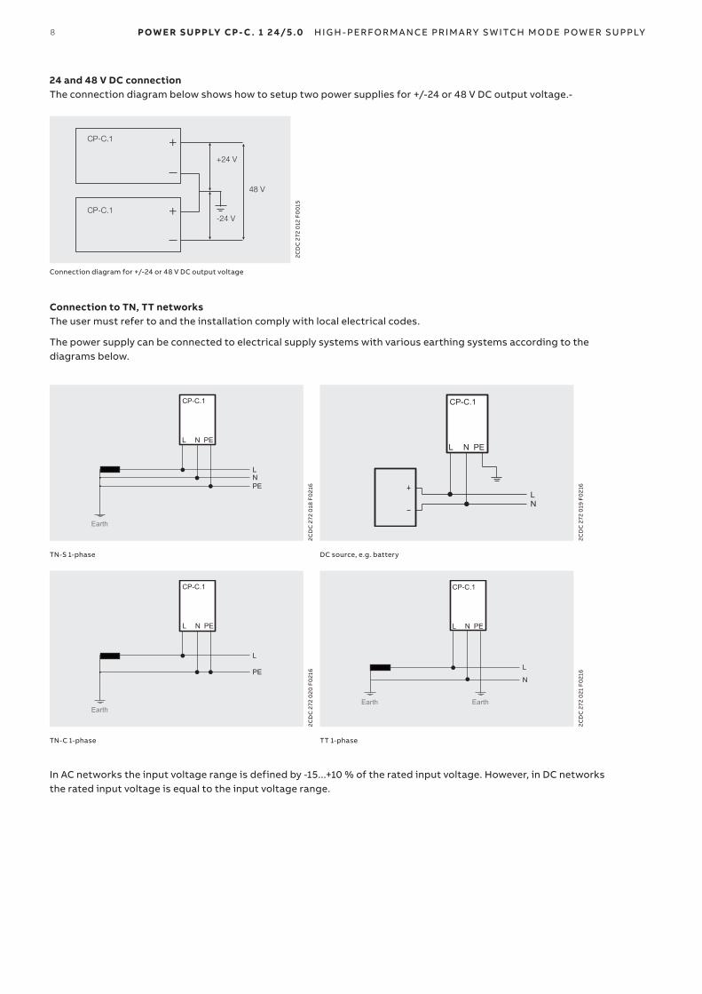
24 and 48 V DC connectionThe connection diagram below shows how to setup two power supplies for +/-24 or 48 V DC output voltage.-
-24 V
+24 V
48 V
+
CP-C.1
CP-C.1
+
2CD
C 2
72 0
12 F
00
15
Connection diagram for +/-24 or 48 V DC output voltage
Connection to TN, TT networksThe user must refer to and the installation comply with local electrical codes.
The power supply can be connected to electrical supply systems with various earthing systems according to the diagrams below.
Earth
LNPE
CP-C.1
L N PE
2CD
C 2
72 0
18 F
021
6
LN
CP-C.1
L N PE
2CD
C 2
72 0
19 F
021
6
TN-S 1-phase DC source, e.g. battery
Earth
L
PE
CP-C.1
L N PE
2CD
C 2
72 0
20 F
021
6
L
N
CP-C.1
EarthEarth
L N PE
2CD
C 2
72 0
21 F
021
6
TN-C 1-phase TT 1-phase
In AC networks the input voltage range is defined by -15...+10 % of the rated input voltage. However, in DC networks the rated input voltage is equal to the input voltage range.
P OWE R S U PPLY CP- C . 1 24/5.0 H I G H - PER FO R M A NCE PR I M A RY S W ITCH M O DE P OW ER SU PPLY9
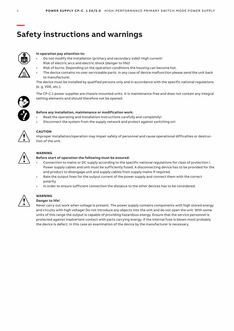
— Safety instructions and warnings
In operation pay attention to:• Do not modify the installation (primary and secondary side)! High current!
Risk of electric arcs and electric shock (danger to life)!• Risk of burns: Depending on the operation conditions the housing can become hot.• The device contains no user serviceable parts. In any case of device malfunction please send the unit back
to manufacturer.The device must be installed by qualified persons only and in accordance with the specific national regulations (e. g. VDE, etc.).
The CP-C.1 power supplies are chassis-mounted units. It is maintenance-free and does not contain any integral setting elements and should therefore not be opened.
Before any installation, maintenance or modification work:• Read the operating and installation instructions carefully and completely!• Disconnect the system from the supply network and protect against switching on!
CAUTIONImproper installation/operation may impair safety of personnel and cause operational difficulties or destruc-tion of the unit.
WARNINGBefore start of operation the following must be ensured:• Connection to mains or DC supply according to the specific national regulations for class of protection I.
Power supply cables and unit must be sufficiently fused. A disconnecting device has to be provided for the end product to disengage unit and supply cables from supply mains if required.
• Rate the output lines for the output current of the power supply and connect them with the correct polarity.
• In order to ensure sufficient convection the distance to the other devices has to be considered.
WARNING Danger to life!Never carry out work when voltage is present. The power supply contains components with high stored energy and circuits with high voltage! Do not introduce any objects into the unit and do not open the unit. With some units of this range the output is capable of providing hazardous energy. Ensure that the service personnel is protected against inadvertent contact with parts carrying energy. If the internal fuse is blown most probably the device is defect. In this case an examination of the device by the manufacturer is necessary.
!
!
!

10 P OWE R S U PPLY CP- C . 1 24/5.0 H I G H - PER FO R M A NCE PR I M A RY S W ITCH M O DE P OW ER SU PPLY
— Technical dataData at Ta = 25 °C, Uin = 230 V AC and rated values, unless otherwise indicated
— Input circuit - Supply circuit
CP-C.1 24/5.0, CP-C.1 24/5.0-L CP-C.1 24/5.0-C
L (+), N (-)
Rated input voltage Uin 100-240 V AC, 90-300 V DC
Input voltage range AC 85-264 V AC, 90-300 V DC
Input current range at rated output power 100-240 V AC 0.6-1.4 A
100-270 V DC 0.5-1.6 A
Typical input current at 115 V AC 1.1 A
at 230 V AC 0.6 A
Typical power consumption at 230 V AC 132 W
Rated frequency DC, 50/60 Hz
Frequency range AC 45-65 Hz
Inrush current, cold state < 8 A
Let-through energy I2t , cold state at 230 V AC < 1 A2s
Discharge current towards PE < 3.5 mA
Hold-up time at 115 V AC min. 50 ms
at 230 V AC min. 50 ms
Internal input fuse T4.0 A, not exchangeable
Recommended backup fuse for wire protection at 1.5 mm2
1 pole miniature circuit breaker ABB type S 200 For USA/CAN: Use appropriate branch circuit 20 A fuse acc. regional and national regulations.
characteristic B or C
max. rating 16 A
Power factor correction (PFC) yes, active
Transient overvoltage protection yes, varistor
— User interface
Indication of operational states
Output voltage LED ‘OUTPUT OK ‘ (green)
ON 92 % adjusted Uout
flashing 90 % adjusted Uout
Power reserve LED ‘I > IR’ (yellow)
OFF I ≤ IR
ON I > IR
P OWE R S U PPLY CP- C . 1 24/5.0 H I G H - PER FO R M A NCE PR I M A RY S W ITCH M O DE P OW ER SU PPLY11
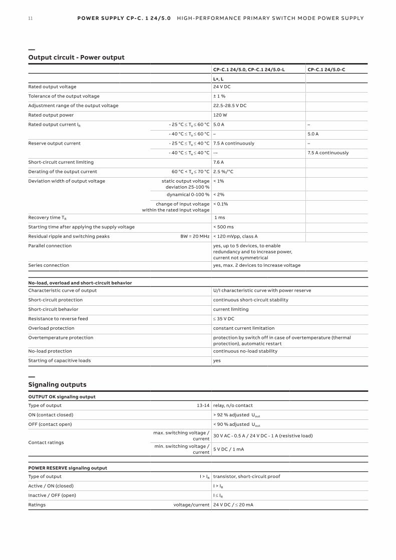
— Output circuit - Power output
CP-C.1 24/5.0, CP-C.1 24/5.0-L CP-C.1 24/5.0-C
L+, L
Rated output voltage 24 V DC
Tolerance of the output voltage ± 1 %
Adjustment range of the output voltage 22.5-28.5 V DC
Rated output power 120 W
Rated output current IR - 25 °C ≤ Ta ≤ 60 °C 5.0 A –
- 40 °C ≤ Ta ≤ 60 °C – 5.0 A
Reserve output current - 25 °C ≤ Ta ≤ 40 °C 7.5 A continuously –
- 40 °C ≤ Ta ≤ 40 °C -– 7.5 A continuously
Short-circuit current limiting 7.6 A
Derating of the output current 60 °C < Ta ≤ 70 °C 2.5 %/°C
Deviation width of output voltage static output voltage deviation 25-100 %
< 1%
dynamical 0-100 % < 2%
change of input voltage within the rated input voltage
< 0.1%
Recovery time TR 1 ms
Starting time after applying the supply voltage < 500 ms
Residual ripple and switching peaks BW = 20 MHz < 120 mVpp, class A
Parallel connection yes, up to 5 devices, to enable redundancy and to increase power, current not symmetrical
Series connection yes, max. 2 devices to increase voltage
No-load, overload and short-circuit behavior
Characteristic curve of output U/I characteristic curve with power reserve
Short-circuit protection continuous short-circuit stability
Short-circuit behavior current limiting
Resistance to reverse feed ≤ 35 V DC
Overload protection constant current limitation
Overtemperature protection protection by switch off in case of overtemperature (thermal protection), automatic restart
No-load protection continuous no-load stability
Starting of capacitive loads yes
— Signaling outputs
OUTPUT OK signaling output
Type of output 13-14 relay, n/o contact
ON (contact closed) > 92 % adjusted Uout
OFF (contact open) < 90 % adjusted Uout
Contact ratings
max. switching voltage / current
30 V AC - 0.5 A / 24 V DC - 1 A (resistive load)
min. switching voltage / current
5 V DC / 1 mA
POWER RESERVE signaling output
Type of output I > IR transistor, short-circuit proof
Active / ON (closed) I > IR
Inactive / OFF (open) I ≤ IR
Ratings voltage/current 24 V DC / ≤ 20 mA
12 P OWE R S U PPLY CP- C . 1 24/5.0 H I G H - PER FO R M A NCE PR I M A RY S W ITCH M O DE P OW ER SU PPLY
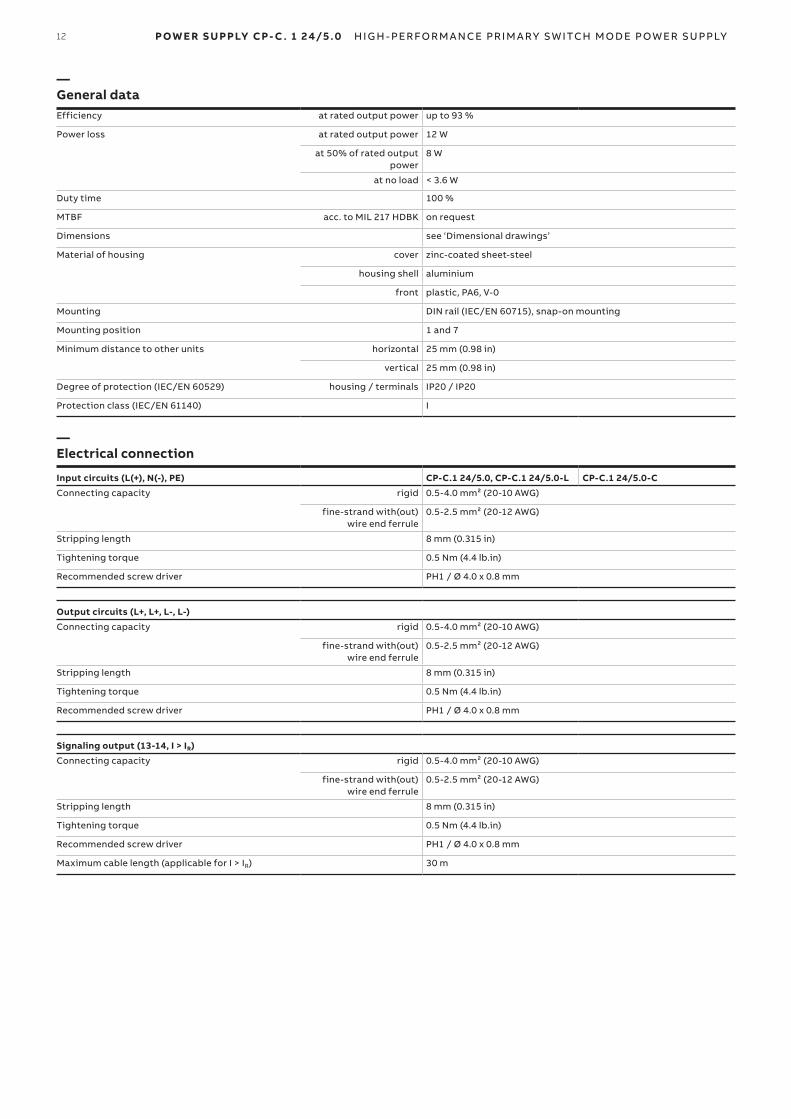
— General dataEfficiency at rated output power up to 93 %
Power loss at rated output power 12 W
at 50% of rated output power
8 W
at no load < 3.6 W
Duty time 100 %
MTBF acc. to MIL 217 HDBK on request
Dimensions see ‘Dimensional drawings’
Material of housing cover zinc-coated sheet-steel
housing shell aluminium
front plastic, PA6, V-0
Mounting DIN rail (IEC/EN 60715), snap-on mounting
Mounting position 1 and 7
Minimum distance to other units horizontal 25 mm (0.98 in)
vertical 25 mm (0.98 in)
Degree of protection (IEC/EN 60529) housing / terminals IP20 / IP20
Protection class (IEC/EN 61140) I
— Electrical connection
Input circuits (L(+), N(-), PE) CP-C.1 24/5.0, CP-C.1 24/5.0-L CP-C.1 24/5.0-C
Connecting capacity rigid 0.5-4.0 mm² (20-10 AWG)
fine-strand with(out) wire end ferrule
0.5-2.5 mm² (20-12 AWG)
Stripping length 8 mm (0.315 in)
Tightening torque 0.5 Nm (4.4 lb.in)
Recommended screw driver PH1 / Ø 4.0 x 0.8 mm
Output circuits (L+, L+, L-, L-)
Connecting capacity rigid 0.5-4.0 mm² (20-10 AWG)
fine-strand with(out) wire end ferrule
0.5-2.5 mm² (20-12 AWG)
Stripping length 8 mm (0.315 in)
Tightening torque 0.5 Nm (4.4 lb.in)
Recommended screw driver PH1 / Ø 4.0 x 0.8 mm
Signaling output (13-14, I > IR)
Connecting capacity rigid 0.5-4.0 mm² (20-10 AWG)
fine-strand with(out) wire end ferrule
0.5-2.5 mm² (20-12 AWG)
Stripping length 8 mm (0.315 in)
Tightening torque 0.5 Nm (4.4 lb.in)
Recommended screw driver PH1 / Ø 4.0 x 0.8 mm
Maximum cable length (applicable for I > IR) 30 m
P OWE R S U PPLY CP- C . 1 24/5.0 H I G H - PER FO R M A NCE PR I M A RY S W ITCH M O DE P OW ER SU PPLY13
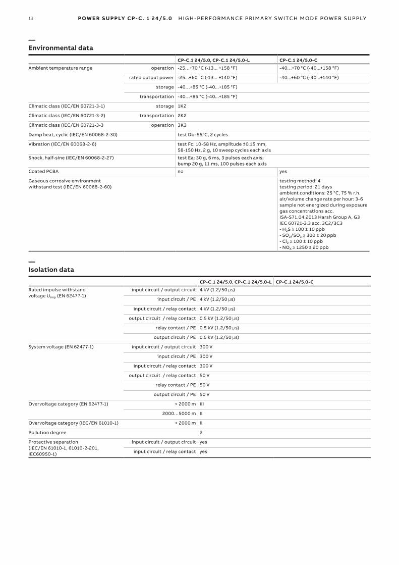
— Environmental data
CP-C.1 24/5.0, CP-C.1 24/5.0-L CP-C.1 24/5.0-C
Ambient temperature range operation -25…+70 °C (-13... +158 °F) -40…+70 °C (-40...+158 °F)
rated output power -25...+60 °C (-13... +140 °F) -40...+60 °C (-40...+140 °F)
storage -40…+85 °C (-40...+185 °F)
transportation -40…+85 °C (-40...+185 °F)
Climatic class (IEC/EN 60721-3-1) storage 1K2
Climatic class (IEC/EN 60721-3-2) transportation 2K2
Climatic class (IEC/EN 60721-3-3 operation 3K3
Damp heat, cyclic (IEC/EN 60068-2-30) test Db: 55°C, 2 cycles
Vibration (IEC/EN 60068-2-6) test Fc: 10-58 Hz, amplitude ±0.15 mm,58-150 Hz, 2 g, 10 sweep cycles each axis
Shock, half-sine (IEC/EN 60068-2-27) test Ea: 30 g, 6 ms, 3 pulses each axis; bump 20 g, 11 ms, 100 pulses each axis
Coated PCBA no yes
Gaseous corrosive environment withstand test (IEC/EN 60068-2-60)
testing method: 4 testing period: 21 daysambient conditions: 25 °C, 75 % r.h. air/volume change rate per hour: 3-6 sample not energized during exposure gas concentrations acc.ISA-S71.04.2013 Harsh Group A, G3 IEC 60721-3.3 acc. 3C2/3C3- H2S ≥ 100 ± 10 ppb- SO2/SO3 ≥ 300 ± 20 ppb- Cl2 ≥ 100 ± 10 ppb- NOX ≥ 1250 ± 20 ppb
— Isolation data
CP-C.1 24/5.0, CP-C.1 24/5.0-L CP-C.1 24/5.0-C
Rated impulse withstand voltage Uimp (EN 62477-1)
input circuit / output circuit 4 kV (1.2/50 µs)
input circuit / PE 4 kV (1.2/50 µs)
input circuit / relay contact 4 kV (1.2/50 µs)
output circuit / relay contact 0.5 kV (1.2/50 µs)
relay contact / PE 0.5 kV (1.2/50 µs)
output circuit / PE 0.5 kV (1.2/50 µs)
System voltage (EN 62477-1) input circuit / output circuit 300 V
input circuit / PE 300 V
input circuit / relay contact 300 V
output circuit / relay contact 50 V
relay contact / PE 50 V
output circuit / PE 50 V
Overvoltage category (EN 62477-1) < 2000 m III
2000…5000 m II
Overvoltage category (IEC/EN 61010-1) < 2000 m II
Pollution degree 2
Protective separation (IEC/EN 61010-1, 61010-2-201, IEC60950-1)
input circuit / output circuit yes
input circuit / relay contact yes
14 P OWE R S U PPLY CP- C . 1 24/5.0 H I G H - PER FO R M A NCE PR I M A RY S W ITCH M O DE P OW ER SU PPLY
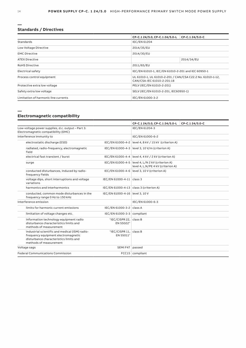
— Standards / Directives
CP-C.1 24/5.0, CP-C.1 24/5.0-L CP-C.1 24/5.0-C
Standards IEC/EN 61204
Low Voltage Directive 2014/35/EU
EMC Directive 2014/30/EU
ATEX Directive 2014/34/EU
RoHS Directive 2011/65/EU
Electrical safety IEC/EN 61010-1, IEC/EN 61010-2-201 and IEC 60950-1
Process control equipment UL 61010-1, UL 61010-2-201 / CAN/CSA C22.2 No. 61010-1-12, CAN/CSA-IEC 61010-2-201:18
Protective extra low voltage PELV (IEC/EN 61010-2-201)
Safety extra low voltage SELV (IEC/EN 61010-2-201, IEC60950-1)
Limitation of harmonic line currents IEC/EN 61000-3-2
— Electromagnetic compatibility
CP-C.1 24/5.0, CP-C.1 24/5.0-L CP-C.1 24/5.0-C
Low-voltage power supplies, d.c. output – Part 3: Electromagnetic compatibility (EMC)
IEC/EN 61204-3
Interference immunity to IEC/EN 61000-6-2
electrostatic discharge (ESD) IEC/EN 61000-4-2 level 4, 8 kV / 15 kV (criterion A)
radiated, radio-frequency, electromagnetic field
IEC/EN 61000-4-3 level 3, 10 V/m (criterion A)
electrical fast transient / burst IEC/EN 61000-4-4 level 4, 4 kV / 2 kV (criterion A)
surge IEC/EN 61000-4-5 level 4, L/N 2 kV (criterion A) level 4, L,N/PE 4 kV (criterion A)
conducted disturbances, induced by radio-frequency fields
IEC/EN 61000-4-6 level 3, 10 V (criterion A)
voltage dips, short interruptions and voltage variations
IEC/EN 61000-4-11 class 3
harmonics and interharmonics IEC/EN 61000-4-13 class 3 (criterion A)
conducted, common mode disturbances in the frequency range 0 Hz to 150 kHz
IEC/EN 61000-4-16 level 3, 10 V
Interference emission IEC/EN 61000-6-3
limits for harmonic current emissions IEC/EN 61000-3-2 class A
limitation of voltage changes etc. IEC/EN 61000-3-3 compliant
information technology equipment radio disturbance characteristics limits and methods of measurement
"IEC/CISPR 22, EN 55022"
class B
industrial scientific and medical (ISM) radio-frequency equipment electromagnetic disturbance characteristics limits and methods of measurement
"IEC/CISPR 11, EN 55011"
class B
Voltage sags SEMI F47 passed
Federal Communications Commission FCC15 compliant
P OWE R S U PPLY CP- C . 1 24/5.0 H I G H - PER FO R M A NCE PR I M A RY S W ITCH M O DE P OW ER SU PPLY15
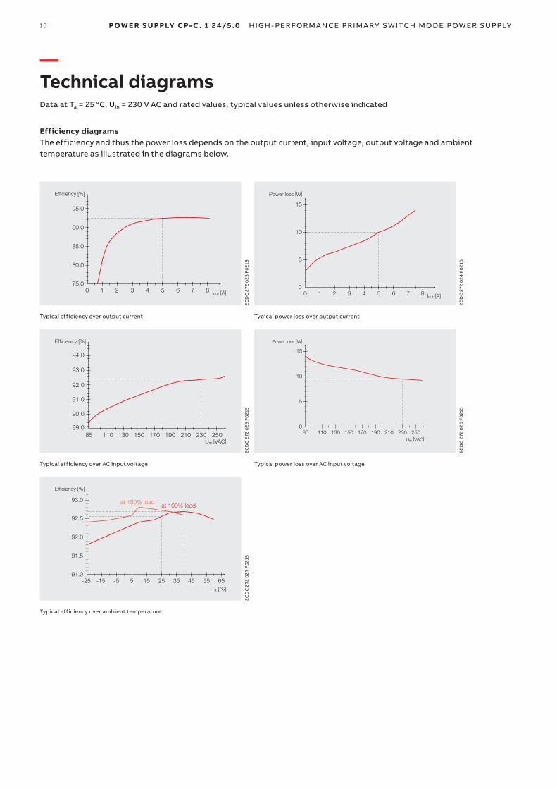
— Technical diagramsData at Ta = 25 °C, Uin = 230 V AC and rated values, typical values unless otherwise indicated
Efficiency diagramsThe efficiency and thus the power loss depends on the output current, input voltage, output voltage and ambient temperature as illustrated in the diagrams below.
Efficiency [%]
Iout [A]0 1 2 3 4 7 86575.0
80.0
85.0
90.0
95.0
2CD
C 2
72 0
23 F
021
5
Power loss [W]
Iout [A]0
15
10
5
1 2 3 4 7 8650
2CD
C 2
72 0
24 F
021
5
Typical efficiency over output current Typical power loss over output current
Efficiency [%]
Uin [VAC]230 25021085 110 130 150 170 190
90.0
91.0
92.0
93.0
94.0
89.0
2CD
C 2
72 0
25 F
021
5
Power loss [W]
15
10
5
0
Uin [VAC]85 230 250210110 130 150 170 190
2CD
C 2
72 0
26 F
021
5Typical efficiency over AC input voltage Typical power loss over AC input voltage
Efficiency [%]
Ta [°C]-25 -15 -5 5 15 25 35 45 55 65
91.0
91.5
92.0
92.5
93.0at 100% loadat 150% load
2CD
C 2
72 0
27 F
021
5
Typical efficiency over ambient temperature
16 P OWE R S U PPLY CP- C . 1 24/5.0 H I G H - PER FO R M A NCE PR I M A RY S W ITCH M O DE P OW ER SU PPLY
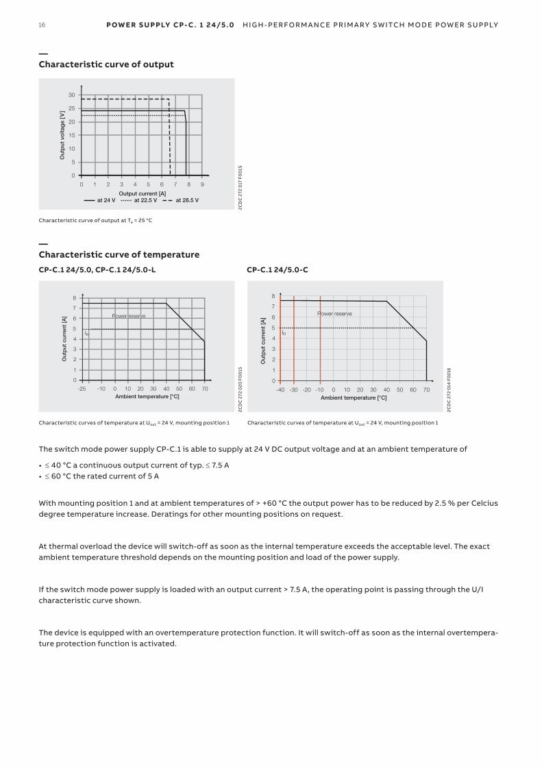
— Characteristic curve of output
at 24 V at 22.5 V at 28.5 V Output current [A]
0
5
10
15
20
25
30
0 1 2 3 4 5 6 7 8 9
Out
put
vo
ltag
e [V
]
2CD
C 2
72 0
17 F
00
15
Characteristic curve of output at Ta = 25 °C
— Characteristic curve of temperature
CP-C.1 24/5.0, CP-C.1 24/5.0-L CP-C.1 24/5.0-C
Ambient temperature [°C]
0
1
2
3
4
5
6
7
8
-25 -10 0
Power reserve
IR
10 20 30 40 50 60 70
Out
put
cur
rent
[A]
2CD
C 2
72 0
20 F
00
15
IR
Ambient temperature [°C]
Power reserve
Out
put
cur
rent
[A]
-10 0 10 20 30 40 50 60 70-20-30-40
0
1
2
3
4
5
6
7
8
2CD
C 2
72 0
14 F
021
6
Characteristic curves of temperature at Uout = 24 V, mounting position 1 Characteristic curves of temperature at Uout = 24 V, mounting position 1
The switch mode power supply CP-C.1 is able to supply at 24 V DC output voltage and at an ambient temperature of
• ≤ 40 °C a continuous output current of typ. ≤ 7.5 A• ≤ 60 °C the rated current of 5 A
With mounting position 1 and at ambient temperatures of > +60 °C the output power has to be reduced by 2.5 % per Celcius degree temperature increase. Deratings for other mounting positions on request.
At thermal overload the device will switch-off as soon as the internal temperature exceeds the acceptable level. The exact ambient temperature threshold depends on the mounting position and load of the power supply.
If the switch mode power supply is loaded with an output current > 7.5 A, the operating point is passing through the U/I characteristic curve shown.
The device is equipped with an overtemperature protection function. It will switch-off as soon as the internal overtempera-ture protection function is activated.
P OWE R S U PPLY CP- C . 1 24/5.0 H I G H - PER FO R M A NCE PR I M A RY S W ITCH M O DE P OW ER SU PPLY17
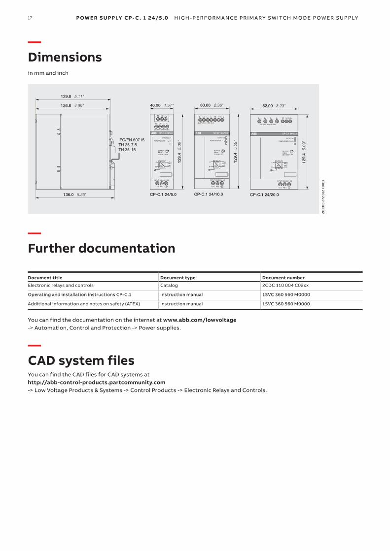
— Dimensionsin mm and inch
L(+) N(-)
L+
OUTPUT 24 V DC 5 A
L+ L- L-
13 14
INPUT 100-240 V AC
OUTPUT OK
OUTPUTAdjust22.5-28.5 V
CP-C.1 24/5.0
I > IRPOWER RESERVE
L-PWMN
L+L
L-L+
RI>I
40.00 1.57"
129.
4 5
.09"
L+ L+ L- L-
OUTPUT 24 V DC 10 A
INPUT 100-240 V AC
13 14
OUTPUTAdjust22.5-28.5 V
L-PWMN
L+L
L-L+
OUTPUT OK
I > IRPOWER RESERVE
CP-C.1 24/10.0
L(+) N(-)
RI>I
60.00 2.36"
129.
4 5
.09"
CP-C.1 24/20.0
L+ L-
OUTPUT 24 V DC 20 A
L+ L-
L(+) N(-)
INPUT 100-240 V AC
13 14 RI>I
OUTPUT OK
I > IRPOWER RESERVE
L-PWMN
L+L
L-L+
OUTPUTAdjust22.5-28.5 V
82.00 3.23"
129.
4 5
.09"
126.8 4.99"
136.0 5.35"
129.8 5.11"
IEC/EN 60715TH 35-7.5TH 35-15
CP-C.1 24/20.0CP-C.1 24/10.0CP-C.1 24/5.0
2DC
DC
272
012
F0
017
— Further documentation
Document title Document type Document number
Electronic relays and controls Catalog 2CDC 110 004 C02xx
Operating and installation instructions CP-C.1 Instruction manual 1SVC 360 560 M0000
Additional information and notes on safety (ATEX) Instruction manual 1SVC 360 560 M9000
You can find the documentation on the internet at www.abb.com/lowvoltage -> Automation, Control and Protection -> Power supplies.
— CAD system filesYou can find the CAD files for CAD systems at http://abb-control-products.partcommunity.com -> Low Voltage Products & Systems -> Control Products -> Electronic Relays and Controls.

—We reserve the right to make technical changes or modify the contents of this document without prior notice. With regard to purchase orders, the agreed particulars shall prevail. ABB AG does not accept any responsibility whatsoever for potential errors or possible lack of information in this document.
We reserve all rights in this document and in the subject matter and illustrations contained therein. Any reproduction, disclosure to third parties or utilization of its contents – in whole or in parts – is forbidden without prior written consent of ABB AG. Copyright© 2021 ABB AG.All rights reserved
abb.com/lowvoltage
—ABB STOTZ-KONTAKT GmbHEppelheimer Straße 8269123 Heidelberg, Germany
2CD
C11
40
99
D0
201
Rev
. G (0
8/20
21)