D Df C - DTIC
242
ILEVE MARITIME PATROL AIRSHIP CONCEPT STUDY Contract N62269-78-M-69S6 ( J. C. Bell, D Df J. D. Marketos, and A. D. Topping ".. Bell Aerospace Textron N 9 9 Division of Textron, Inc. JUN 1919 Post Office Box 29307 ti l New Orleans, La. 70189 U L C November 16, 1978 Final Report C. ___ Unlimited Distri.bution. Prepared for NAVAL AIR DEVELOPMENT CENTER (CODE 6096) Warminster, Pennsylvania 18974 RMhW102 STATISM, t X Appzc.d for public .la Dimtkibutt Uuflmhsd 79 (1~(
-
Upload
khangminh22 -
Category
Documents
-
view
0 -
download
0
Transcript of D Df C - DTIC
ILEVE
MARITIME PATROL AIRSHIP CONCEPT STUDYContract N62269-78-M-69S6
(
J. C. Bell, D DfJ. D. Marketos, andA. D. Topping
".. Bell Aerospace Textron N 9 9Division of Textron, Inc. JUN 1919Post Office Box 29307 ti lNew Orleans, La. 70189 U L
C
November 16, 1978
Final Report
C.
___ Unlimited Distri.bution.
Prepared for
NAVAL AIR DEVELOPMENT CENTER (CODE 6096)Warminster, Pennsylvania 18974
RMhW102 STATISM, t XAppzc.d for public .la
Dimtkibutt Uuflmhsd
79 (1~(

UNCLASSIFIED -
WURIuTV CLASIFCATION OF Vasil PAC DWS go ae@________________
N AD 8 74-6 L,
ITIMM PATROL AIRSHIP CONCEPT STUDY& IA RPR
1 A. D. Topping Textron69-ew8-M-69S6
Post Office Box 29307New Orleans, La. 70189- .ASmY01
KI CONTOO.LLSM OFSPCg WANg AND AOOR91S A ROT
NAVAL AIR DEVELOPMENT CENTER (CODE 6096) November 16, 1978WARMINSTER, PENNSYLVANIA 18974 13. UMER OF PAQcS
I ~,rt~oI v~pt ~UNCLASSIFIED
APPROVED~I 0 DSTIBUIO UNIMTE
Is. ft5TILUI@W STATSgN" (Of 01 nor-")tEi sa e i I~ b m
APPROVED FOR PUBLIC RELEASE; DISTRIBUTION UNLIMITED
IL SUP01.s961TAmv Notgs
l.-I eSy 001Rn (Castafto sm ",we* side of mocee..m OWd I#bmfi4 or iha Awhe
LigI'ter-thari-Rir craft; airships; coastal patrol
[ -"Results of a preliminiary concerptual paramo~tric design study for a maritimepatro) airship to be used by the U.S. Coast Guard or Navy are presented.Eight different Coast Guare mission jrofiles_-specified by thfo Naval AirDevelopment Cotitar ltttftidred, and an optimum airship point design isdeveloped for e&ch. The report discusses 4tW'mission requirements, tihe' airshipI:joperational req~uirements, the conceptual design approach, and the parhametricdesign study which us.es a computer program to assist in -ptjimizing the criticalparameters for each airship mission design.- ~'~~fi~anie itgswr
P~f? or~ I~~ *a-)-W. ra it o2 #5oubI UNCLASSIFIED
36CUSTTCfMit =FZV-V To A( fw 00.
I UNCLASSIFIED68CU~MV CLAS*S1fCA14 of' T1u06 PAegftUf " M -0)
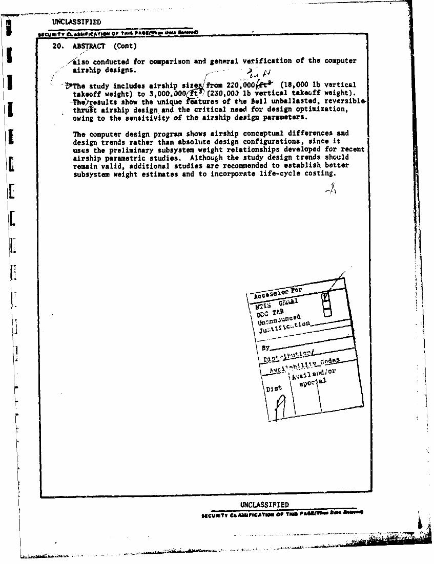
20. ABSTRACT (Cont),4lso conducted for comparison and general verification of the computer
airshp deigns
I -the study includes airship size from 22*0,000 ~ft& (18,000 lb verticaltakeoff weight) to 3,000,000(t' (230,000 lb vertical takeoff weight).
-The>_ esults show the unique Mitures of the Bell unballasted, reversible.Ihuf airship design. and the critical need for design optimization,owing to the sensitivity of the airship design parameters.
The computer design program shows airship conceptual differences andI design trends rather than absolute design configurations, since ituses the preliminary subsystem weight relationships developed for recentairship parametric studies. Although the study design trends shouldIi remain valid, additional studies are recommended to establish better
subsystem weight estimates and to incorporate life-cycle costing.
[1
LoLCC
i _ A
UNCLASSIFIED
sgCUmeTV C&.AamFC*TW OF TNA P&Wub&M 04" an"
I.
II
-I
~~I'
*1. p'zz.H*1.
HI.-. V
fr
DMmon of Textron Inc
CONTENTS
cON EN S . . . .. . . . . . . . . . . . . . . . 1LIST OF FIGURES . . . . . . . ........... 2LIST OF TABLES ...... .................... 3INTRODUCTION . . . . . . . . .......... .. 4
Section 1 MISSION REQUIREMENTS . .... . .. . . . . . ... 62 OPERATIONAL REQUIRE MENTS . ................. 93 DESIGN CONCEPT ........ .... ........ . .. 11
C-onfiguration Description. .... . . . . . . . . . . . 12Operational Description ...... . . . ... . 17Design Approach .......... ............ 23Subsystem Design Tradeoffs. ........... .31
4 PARAMETRIC SIZE, WEIGHT, ANDPERFORMANCE TRADEOFFS... ............. 35
Program Description .... ............... ... 41Program Sequence ...... .............. ... 46Computer Design Results ..... ............. SO
s MPA POINT DESIGN SELECTION ... ............. ... 676 CONCLUSIONS ........ ................. 737 RECOI4MENDATIONS . . ....... .... .... .. 74
REFERENCES ...... ..................... ... 76
APPENDIX A, BELL AEROSPACE TEXTRON RENDEZVOUS 40
APPENDIX B, BELL AEROSPACE TEXTRONRENDEZVOUS - INTO THE 80's
APPENDIX C, BELL HELICOPTERS
APPENDIX D, BELL HELICOPTER TEXTRONMODEL 301 TILT-ROTOR AIRCRAFT
APPENDIX E, CURRENT UNITED STATES COAST GUARDPROGRAM OBJECTIVES AND DESCRIPTIONS
APPENDIX F, MPA MISSION PROFILES AND PAYLOADS
APPENDIX G, SIMPLIFIED MANUAL APPROACH FORMARITIME PATROL AIRSHIP DESIGN
APPENDIX H, FUEL CONSUMPTION ANALYSIS
APPENDIX I, SUBSYSTEM DESIGN INVESTIGATIONS
DIvon of Txtron Inc
FIGURES
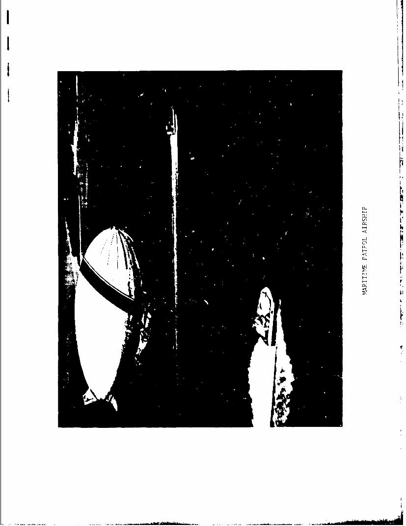
FIGURE I Maritime Patrol Airship. . . . . . . . ...... . 132 NASA/Army/Bell XV-lS Tilt-Rotor Res.arch
Craft (Model 301). ............. .. . . 143 Airship Automatic Mooring Mast Engagement Technique . 160 Airship Mooring and Tie-Down System .... ......... 18S Flotation and Sea Anchor System. ........... .... 196 Demonstration of Flotation Stability
of Vertical Floats . . .._ . .... 207 Reversible-Thrust MPA Flight Operation (ELT M.ssion) 218 Simulated Coast Guard Mission Monitoring
Offshore Oil Rigs ........ ........ 249 Coast Goard Airship Approaching Hover Target ...... 25
10 Airship Cockpit View of Low-SpeedApproach to Hover Target ...... .............. 26
11 X-22A Tri-Service V/STOL ...... ........ 3012 Effect of Rotor Vertical Placement on Hull Loads
of Heavy-Lift Airship in Crossflow (Ref 1) ..... .... 3313 Horsepower Required Versus Airspeed ......... 3714 Propulsio System Weight Versus Rotor Lifting Capacity 43is Propulsion System Weight Versus Airship
Volume for HLA with RT/DL a 1.0 ........ ...... 4416 Useful Load Versus Airship Volume for
HLA with RT/DL 1. 0. . ... . .. ... .... 4517 Airship Volume and Weight Versus Buoyancy
Ratio for ELTMission ........ ...... .5. . Si18 Airship Volume and Weight Versus Buoyancy
Ratio for MEP Mission ........ .... ... . 5219 Airship Volume and Weight Versus Buoyancy
Ratio for SAR Mission. . . . . ........ .... 5320 Airstip Volume and Weight Versus Buoyancy
Ratio for MO/MP Mission ........ ... ... . 5421 Airship Voltne and Weight Versus Buoyancy
Ratio for PSS Mission ..... .............. SS22 Airship Volume and Weight Versus Buoyancy
Ratio for A/N Mission ...... .. . ...... S623 Airship Volume and Weight Versus Buoyancy
Ratio for MSA Mission ........ ... ....... 5724 Airship Volume and Weight Versus Buoyancy
Ratio for 10 Mission ..... ..... ... 582S Airship Vol%=e Versus Buoyancy R;tio for'
Various M'A Missions. . . . . . .... ......... 6826 Airship Volume Versus Maximum Attainable
Speed for Various Missions ..... ...... . . 6927 Comparison of MPA Computer Results with Historical
Airship Unit Weight Versus Volume . . . . . . . . 7128 Comparison of MPA Computer Results with Historical
Airship Useful Lift Vercus Volume . . . . . . . .. 72
2

Dmoon of Textron Inc
TABLES
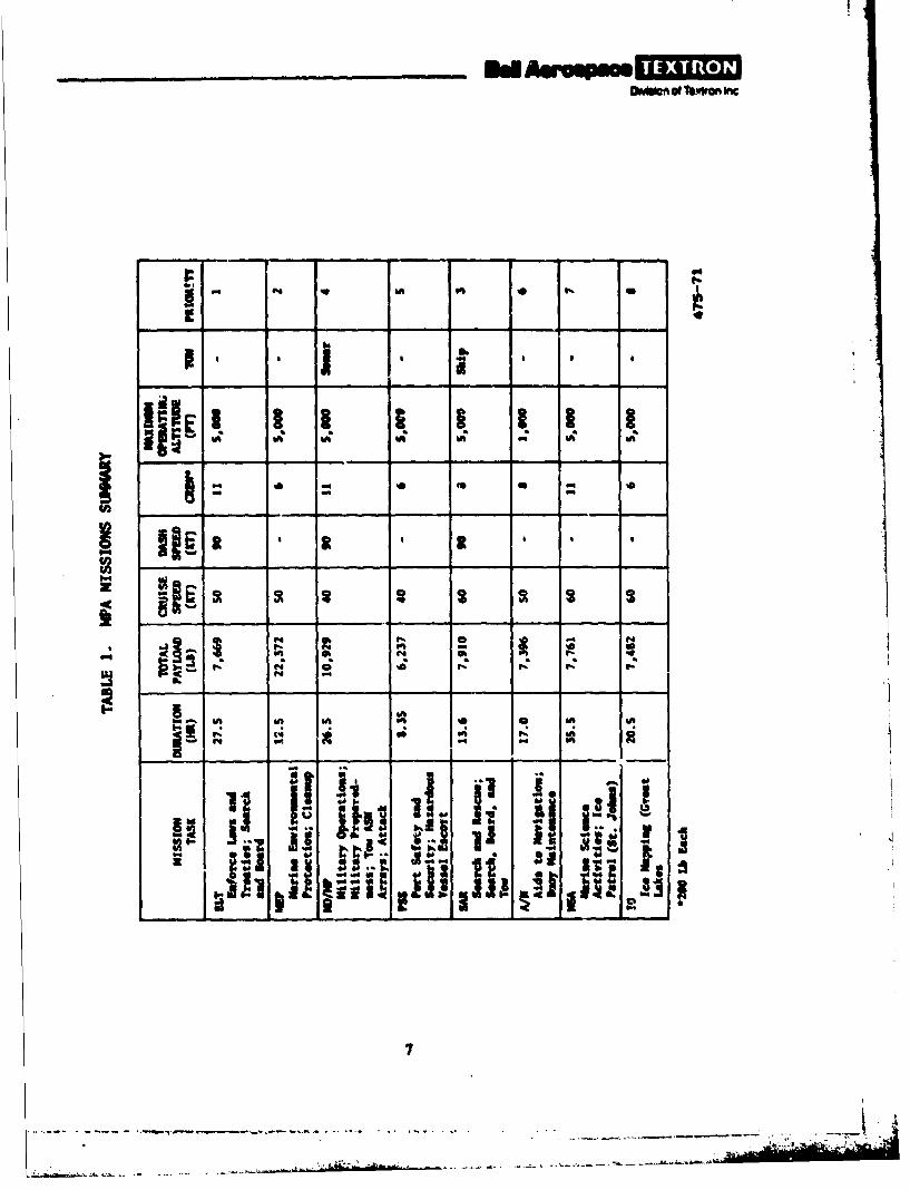
TABLE I MPA Missions Summary... . ........ . . 72 MPA Mission Payload Sumary . . . . . . . . . . . . . 83 ELT Mission MPA Weight and Rotor
Sizing Estimate . ... ........... ... 384 Maritime Patrol Airship Computer
Design Swmary. . . ... .......... . S95 Some Values of k Versus Volume,
Fuel Weight for Eicht Missions ..... ........... 62
3
Dv~uion of Toxron Inc.
i.% NTRODI CTI ON
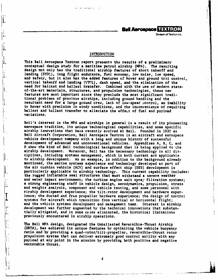
This Bell Aerospace Textron report presents the results of a preliminaryconceptual design study for a maritime patrol airship (N4PA). The resultingdesign not only has the traditional airship features of short takeoff andlanding (STO?), long flight endurance, fuel economy, low noise, low speed,and safety, but it also has the added features of hover and ground ttxi control,vertical takeoff and landing (.V ML), dash speed, and the elimination of theneed for ballast and ballast transfer. Combined with the use of modern state-of-the-art materials, structures, and propulsion technologies, these newfeatures are most important since they preclude the most significant tradi-tional problems of previous airships, including ground handling and theresultant need for a large ground crew, lack of low-speed control, an inabilityto hover with precision in windy conditions, and the inconvenience of requiringballast and ballast transfer to alleviate the effeLt of fuel and payloadvariations.
Bell's interest in the MPA and airships in general is a result of its pioneeringaerospace tradition, its unique technological capabilities, and some specificairship innovations that have recently evolved at Bell. Founded in 193F asBell Aircraft Corporation, Bell Aerospace Textron is an aircraft and aerospacevehicle development company with a long and unique history of successfuldevelopment of advanced and unconventional vehicles. Appendixes A, B, C, andD show the kind of Bell technological background that is being applied to theairship development. Moreover, Bell has the necessary technology in all dis-ciplines, including systems management, which is both currant and applicableto airship development. As an example, in addition to the background alreadymentioned, the marine systems experience and technology developed as part ofthe air cushion vehicle (ACV) and surface effect ship (SES) development isparticularly applicable to airship technology. This current capability includes:the rugged inflatable seal structures that must withstand a severe weather
*and water impact environment; the turbine engine salt spray filtration systems;a strong engineering staff in vehicle design, aerodynamics, propulsion, stressand weights analysis, component and vehicle testing, and some personnel withtirship development experience; the tilt-rotor development and hardware exper-ience; the ducted and frte propeller hardware experience; the design of colitrolsystems for aircraft which transition from vertical or horizontal flight;and the vehicle systems development and management team. Interest in airshipdevelopment was further augmented by the technical innovations that substan-
4 tially mitigated, and in some cases eliminated, the historical limitationspreviously encountered in airship operations.
The Bell MPA design, designated the Unballasted Reversible-Thrust Airship(URTA), has achieved its unique features by optimizing the vehicle buoyancyratio and by providing a quad-rotor/tilt-propeller, reversible-thrust rotorpropulsion system that can deliver extremely good control ability with anypayload at any point in the mission by providing both positive and negativevectorable thrust.
4
- OD~ of Teptton inc
The objectives for Bell ir the U.S. Navy/U.S. Coast Guard MPA Atudy were todevelop conceptual vehicle designs to satisfy representative mission profilesprovided by the contracting agency.
This report includes a brief d$scussion of mission definition and mission pro-files provided by the Naval Air Development Center (NADC); a description ofthe vehicle concept and its operational characteriitivs; a discussion of com-puter and manual parametric tradeoff studies of airship size, weight, andperformance; and a description of the preliminary point design configuration.
I
S'

omgAof' CA Textron Inc
I. MISSION REQUIREMENTS
The various maritime roles considered for the MPA are listed below:
a. ENFORCEMENT OF LAWS AND TREATIES (ELT)
b. MAR;NE ENVIRONMENTAL PROTECTION (MEP)
c. MILITARY OPERATIONS/PREPAREDNESS (MO/MP)
d. PORT SAFETY AND SECURITY (PSS)
e. SEARCH AND RESCUE (SAR)
f. SHORT-RANGE AIDS TO NAVIGATION (A/N)
g. MARINE SCIENCE ACTIVITIES (MSA)
h. ICE OPERATIONS (10).
These progams establish the perfozmance requirements for the airship. Theydetermine the needs for surveillance, trail, search and rescue, board andentry, marine pollution control, and other activities. Each program ischaracterized by a representative mission profile which specifies a sequenceof operations or maneuvers .a be executed from takeoff to landing.
The missions and mission profiles for each of the eight missions have beenprovided by NADC, and are presented in appendixes E and F for easy reference.Table I presents a sumary of perfornance and payload requirements for eachmission profile. Table 2 presents a breakdown of the MPA mission payloads.
6
Omnt Thi410A mC
! h" -
O A 04
OA W; in
IA IA l 01 . ilA li IA| i I A.. <
0 0
a 11i kiC IA I Ls. I IA
?1 0
~j' i dli il I

___________ EdAwo~mOIv~on @4 eMit oe~ Inc
2 ;03135@ ~ ~* a 6 1#~
:~a..,. ~**..** ~* a -* .9..ft .9 s'S
* I 6~,.geu S S.9 #5
.9 . .9~ @mse ' : 5 6 .9- a aC ~. - .9 S.
~~ 3,e,,S*
0. ______________ ______ -
~ ;..f5. ~ j~5 5 5U - 2U, ____________________________ ____________
.9 - -I
___________ _____ ft
* S 55 ~ ... ,,. :. gN - *ft .9 #5
iiI -I
I 14111 '
! 1 i~i 111 s~gal

*1w DMon of Textron Inc
2. OPERATIONAL REQUIREMENTS
The airship design requirements are obviously a function of the intendedmission. Therefore, a primary requirement for sizing an airship point designis a well defined mission. Although separate airship designs were evolvedfor each specifiz airship mission profile in the parametric study, therecommended initial prototype design must be able to perform more than onemission. Several general requirements have-become evident, and designs under
consideration must have:
a. VTOL. Essential for board and search operations, permits use ofsmaller landing fields, permits at-sea replenishment from vessels underway,and allows sea landings.
b. Precision-Hover and Low-Speed Control Capabilities. Required in theELT, MEP, SAR, and A/N mission profiles for hovering; for towing operationsin the MO/MP and SAR missions; and especially for all ground-handling opera-tions.
c. Cruise Speed of About 60 Knots. Required for SAR, MSA, and 10 missionprofiles; and S0 knots needed for ELT, MEP, and A/N missions.
d. Dash Speed of 90 Knots. Needed for ELT, MO/MP, and SAI. missionprofiles.
e. Ability to Hover Over or Land On the Sea Near a Surface Craft.Important for bo&rd and search operat.ons, rescue (rescue equipment is carriedon all missions), and buoy maintenance activity.
f. Ability to Tow a Sonar Array. Essential for the MO/MP mission profile.
g. Ability to Tow a Small Disabled Surface Craft. Required for the SARmission profile.
h. Payload Capability Up to About 22,000 Pounds. Required for the MEP,L mission profile.
i. Endurance Up to About 40 Hours. The MSA mission profile requires3S.S hours, with a 10-percent fuel reserve.
J. Normal Altitue -Capability of SO00 Feet with Full Payload (withballonet capacity to permit a 10,000-foot altitude for emergencies).
I. The added ballonet capacity was included for emergencies and for transcontinentaltransport. The maximum altitude capability of 10,000 feet is possible toachieve with greater flight angles of attack or with reduced load, and has beenstandard in the past. It can easily be provided with oversize ballonets andwithout a significant weight penalty. Although it would be necessary to vent
~.~.9
LI qv
helium if the higher altitude had not been planned before the flight, theadded ballonet capacity would provide safety in the event of an inadvertentaltitude increase due to thermals, and would also provide greater speeds orreduced fuel consmption at altitude emergency conditions, since less thrustis required in the lower-density air. Also, the altitude flexibility could
[= allow the use of more favorable winds and provide better visual conditions.
I
1.
L
10
j, D sion of Textron Inc.
3. DESIGN CONCEPT
The preceding airship requirements, even VTOL and hover in favorable winds,could be met to some degree by previous existing airships. However, Belladvocates certain significant design improvements to show that modern tech-
{ nology and innovation can eliminate some of the limitations that have inhibitedthe use of the earlier airship designs.
Host important of these proposed design improvements is a swiveling, reversible..thrust propulsion system. Its advantages over and above proposed positive-thrust systems are listed below, and these features are discussed throughoutthis report:
,. a. The ability to precision hover, whether the airship is heavy, light,or neutrally buoyant, particularly since gusts can come in any direction andvertical equilibrium must be maintained in all three conditions (see sectionon Design Approach).
b. Reversible thrust, eliminating the need for ballast and ballast trans-fer for normal operations. (However, ballast pickup capability will be main-tained to minimize fuel consumption for extended hover/loiter missions andin case of engine failure in the light condition.)
c. Dovward thrust during ground taxi, which holds the airship to theground and provides controllability in crosswinds, greatly reduces and in someV cases eliminates traditional ground-handling problems and ground crews.
d. Using four vectorable rotors (quad-rotor configuration) with rever-sible thrust, thus positive control in low-speed and hover modes of operation
Lcan be provided.e. The use of four reversible-thrust rotors permits the airship design to
be a smaller, low-cost vehicle with lower fuel and maintenance costs.
The basic, key features of the Bell MPA are superior low-speed control, groundtaxi capability, elimination of traditional ground-handling problems, elimina-tion of the need for ballast or ballast transfer, larger payloads and betterperformance for same airship volume, smaller size with smaller propulsionsystem for lower initial and operating costs, and a unique sea ancho- indfloat combination. These features are primarily a result of the ve,.cledesign concept using the tilt-quad-rotor reversible-thrust propulsion system.However, much added advantage in weight and vehicle size is shown by basicgood engineering design tradeoff optimization of the primary design parameters.This effort, which can be expanded even further, permits the selection ofimproved airship designs by providing improved and smaller aerodynamic envelopeshapes and sizes for lower drag and more efficient envelope structures thatbest fit the various existing propulsion systems. The airship design curvesfor MEP missions shown in section 4 indicate a particularly sharply defined
11
112 I ;,. .. .. ...
LEDvdon of Textron Inc.
optimum suggesting a smaller, higher-speed envelope design may be the best,lowest cost configuration.
However, for the subsystem component weights, weight relatioships used inprevious NASA studies were used in the computer parametric study because cf
V" the limited scope of the program and to give a more direct comparison toprevious airship studies. For this study, it is assumed that all possibleknown weight savings and design improvemA.nts that modern technology couldprovide were used in the formulation of these subsystem weights. As an example,
i|' it would include use of lighter, stronger materials (such as Kevlar fabrics)and suspensions systems and composite materials for a stronger, lightweightcar and structural components. It would also assume the use of some subsystemdesign innovations such as the flotation/sea anchor subsystem described later
I. in this report.
The following sections describe the airship, its oporation, and the conceptual,operational, and design approaches.
CONFIGURATION DESCRIPTION
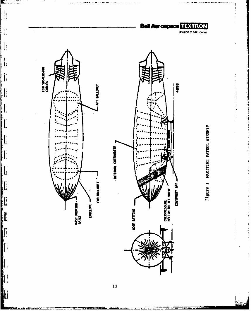
For purposes of this study and the general parametric analysis, a basic configura-tion (figure 1) was assumed having the general features detailed in the following
rparagraphs.The airship was assumed to be a nonrigid pressure airship with conventionalballonets fore and aft, internal suspension systeme nose stiffening, and anLempennage (and X-tail is shown in figure 1). A prime envelope fabric candidateis the standard Dacron-neoprene aluminized on the outside with a tensile strength-I[ to-weight ratio of about SO0,1O0 inches. Other envelope candidates would include
laminated mylar fabric/aluminm foil composites, as well as Kevlar-reinforcedmaterials.
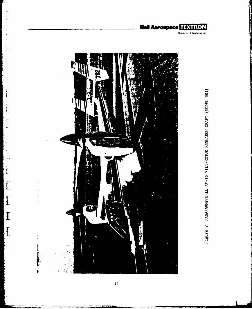
The four turboprop propulsion units are less conventional. They incorporatereversible thrust, and both the turbine engines and propellers are tiltedfrom vertical (up and down) to horizontal for forward flight, and back verticalfor hovering, taxiing, or VTOL. Lateral thrust components for precisionhover in crosswinds is obtained by vectoring the propeller thrust from thehub, or by cyclic pitch. To permit the tilting of the engines and propellers,
they are mounted outboard on outriggers. These propulsion units would bersimilar to those used on the XV-1S (Bell Model 301) aircraft shown in figure 2
(see appendix D for additional details).
The vertical location of the propellers or rotors is difficult to optimizeat this stage. Generally, the lower the rotors, the less the structural weight.However, a report by Neilsen Engineering and Research, Inc., 1 shows some
IS. B. Spangler and C. A. Smith, 2horeti o Study of HuZZ-Rotor Aerodynamic
Interference on Semibu yant Vehioleo (NASA Report CR-1S2127, April 1978).
1 12
____8d MAoinpa -31Ie.OtvWlon of Toxtr0o Inc
a ' ':"
: .. 1 ... i:~l...1 "
: Op
boa... .00..
I Ow a .. .
I IiPPt 4~.:4I'
'3|Li
Division of leximrn Inc
14W4
LLca
144

p
j OMiono Textron Inc
prelimin~ry aerodynamic results from wind tunnel model testing of a heavy liftairship (HLA) which suggests that although some thrust augmentation is obtainedby raising the level of the rotors up to a line 20 degrees below the horizontald-rawn through the center of the envelope, very little is gained above 30 or
even 45 degrees. However, below that, the effective lift of the rotors dropsoff rapidly. Histcrically, a data point is available from the airships Akronand Naoon, which had swiveling propellers used for vertical thrust. Theirpropellers were located at about 37 degrees below the horizontal. For theproposed design, the location of the propellers for the vertical-thrustposition was selected as 30 degrees down from the horizontal. Reference Ialso gives data showing that the rotors should be located as close to the hullas feasible. Cleardnce equal to 0.4 of the rotor radius has been used.
To provide the desired pitch and yaw control, the rotors must be located anappreciable distance apart. A relatively rigid structure is provided betweenthe propulsion units, since the inflated envelope may be expected to berelatively soft in resisting local loads. To a degree then, depending on theseparation of the forward and aft propulsion units, the airship tends to becomea semirigid Lonstruction type.
In the MPA, where there is a large crew and where long mission durations mayrequire accommodations and living space as well as space for fixed and movableequipment, a relatively large car is needed. It makes sense structurally tocombine the car structure with the interconnecting structure between the forwardand aft propulsion units. Since significant speed is a requirement of thefull-scale patrol airship, the car will be streamlined. It will also have windowsfor observation, particularly in the forward end where the pilot's compartmentwill be located.
L .A tricycle landing gear is planned for the airship, consisting of a singlewheel under the forward end of the car and two others at the aft end of thecar and outboard for roll stability. Because of the elevation of the propul-sion units, the legs of the gear would be impractically long if attachedthere, so they are mounted on the propulsion support structure near the sidesof the car. The landing gear is retractable. Each wheel is castered.
[Using downward and horizontal thrust components, the airship can be held stableon the ground and taxied to a mooring mast or even into a hangar in moderate
.crosswinds.
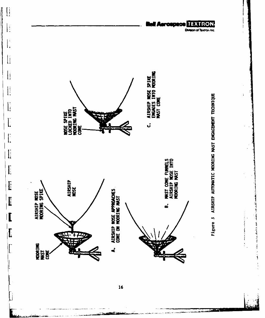
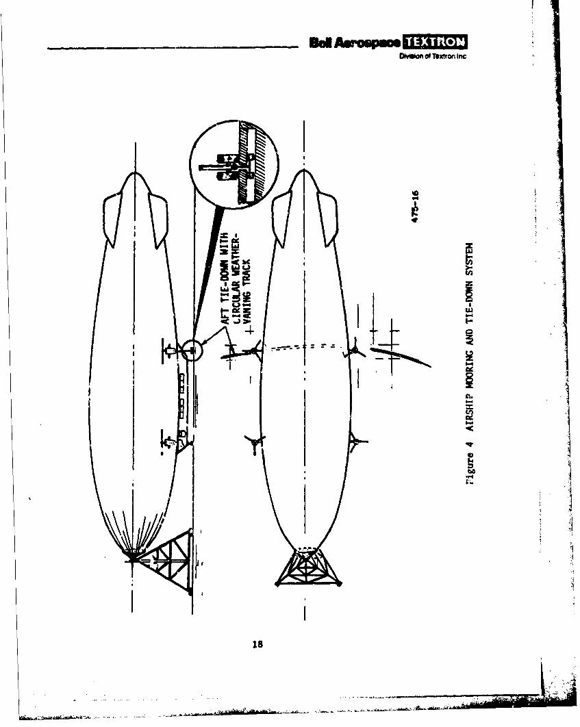
An automatic mooring system is planned for the airship. Although battenstiffening will be used on the airship nose, the conical mooring mast that willbe used appears to be similar to the soft-nose mooring mast which has beendeveloped for tethered balloons. As shown in figure 3, the patrol airship,with its high degree of hover and taxi precision, is nosed into the cone of themooring mast, which guides the nose to the center so that the nose cone spikeof the airship mates and locks into a female fitting at the apex of the cone.
15
IAkD~o of sMOi~ ne
IWEINo
UULL
16.
OinoTex'ron Inc,
The cone with the airship is then free to turn through 360 degrees of azimuth.An aft tie-down line for the airship would use a hook running on a circulartrack. This tie-down hook would attach to the aft landing gear to preventkfting (see figure 4).
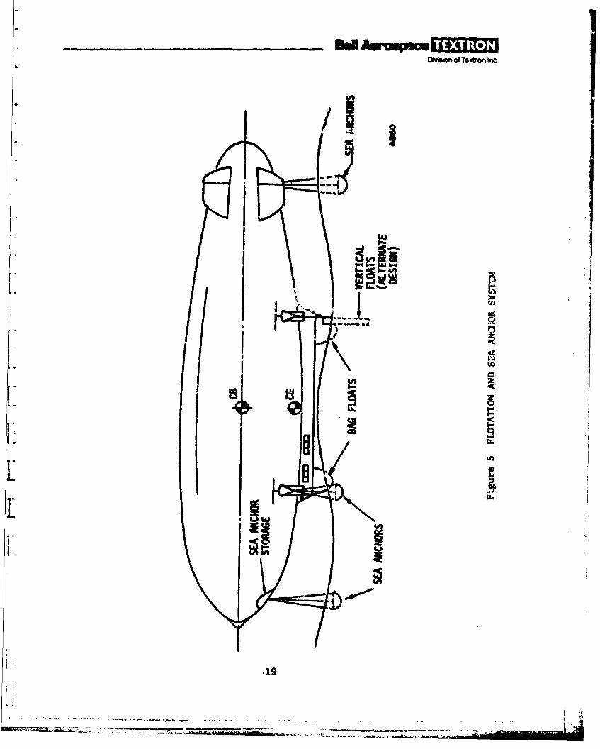
The MPA will have a flotation system to permit water landing at soa, Thissystem is under preliminary study and may result in a combined system offlotation bags and sea anchors (figure 5). However, inflatable, retractable,vertical floats are also being considered. These vertical floats are alsodepicted in figure S.
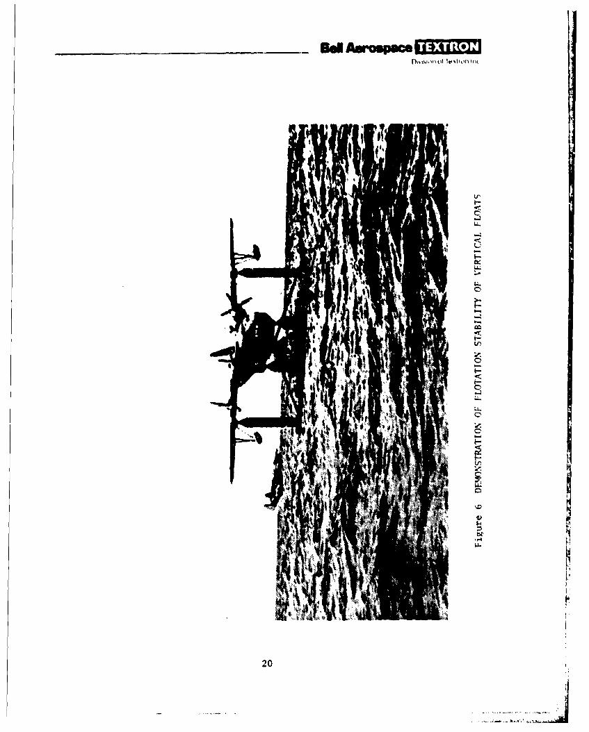
Vertizal floats are being considered because of their inherent stability asflotation devices. Previous tests conducted with vertical floats, such asthe test with the flying boat shown in figure 6, indicate that hiuman toleranceto sea state conditions improves very significantly with use of the verticalfloats.
For added flotation stability sea anchors may be deployed and retracted auto-matically as part of the vertical float deployment and retraction. The floatsare attached to both the main and nose gears. Sea anchors are extended fromnose and tail locations to develep pitching stability in rough-water conditions.
OPERATIONAL DESCRIPTION
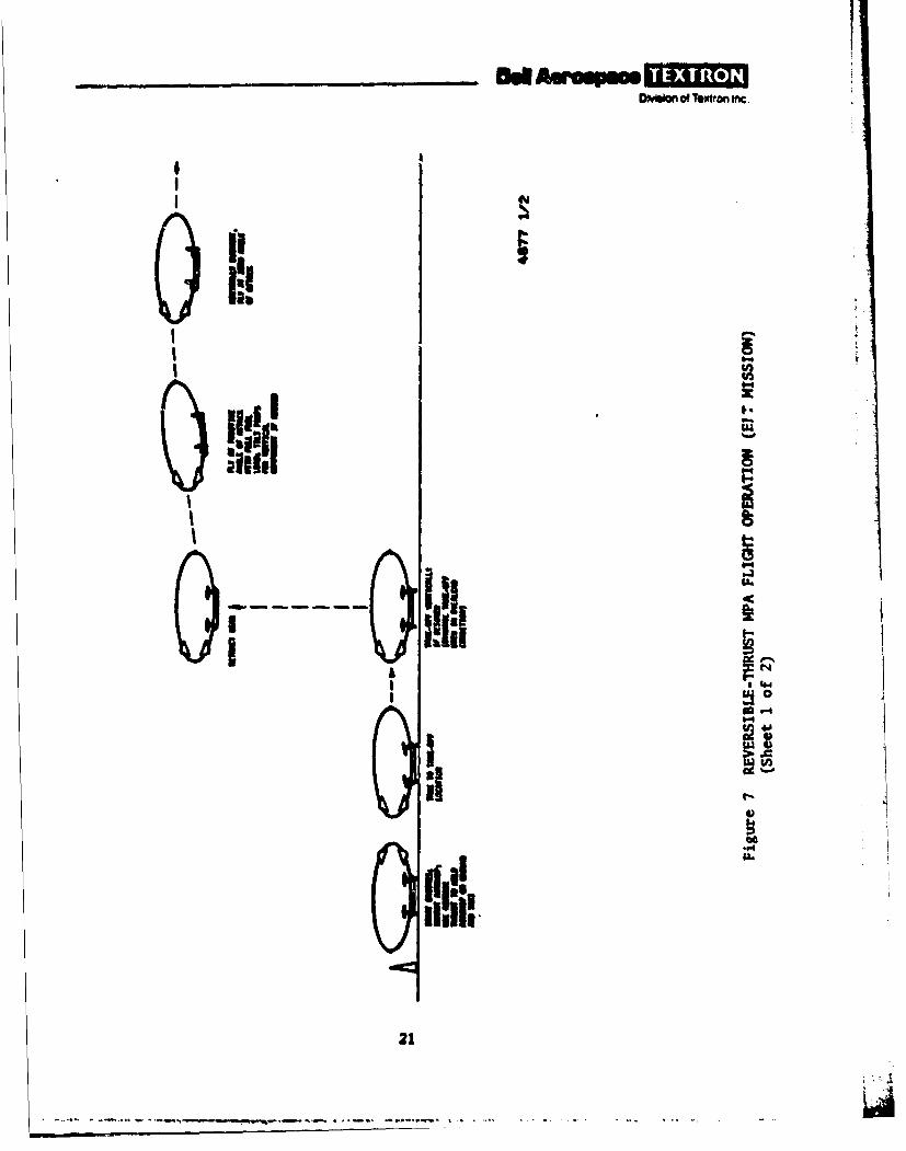
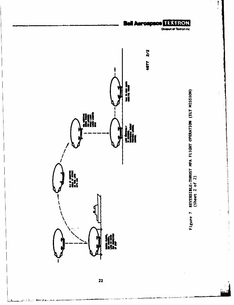
The operational mode of the airship is depicted in figure 7. To start amission, the airship propulsion system is started while still on the mooringmast. (Normally, but not necessarily, loading and refueling are done with theairship on the mast.) Whether light or heavy, the airship uses negative liftto hold itself down and provide ground-taxi capability. The mooring andtie-down attachments are then automatically released, and the airship achieveslateral, forward, and aft ground controllability by using the horizontal com-ponent of the negative thrust vector to steer and propel the craft in thedesired direction.
At takeoff, the WPA may either take off vertically with the rotors thrustingdirectly upward, or it may make a conventional running takeoff down a runwaywith the rotors in a horizontal-thrust position. By inclining the rotorsat some forward angle, a running takeoff with an extra-heavy load could bemade, using dynamic lift from the envelope to augment the buoyant lift andthe vertical-propulsive-thrust component. The iength of takeoff would bea function of the amount of overload; however, most overload takeoff lengthswould be relatively short (on the order of hundreds of feet rather thanthousands).
In flight, the airship is initially heavy, and is flown at a positive angleof attack to provide dynamic lift to offset the heaviness in the conventionalmanner, with engines providing horizontal thrust. If needed, some upward tiltof the engines may be employed. As fuel and supplies are consued, the airshipbecomes lighter, reaching neutral buoyancy when about 60 percent of the fuel
.17
.. . . .. ... . .... .. .... .. ..
_____8d AuWspm -OD hiof Textron inc.
UJ
cc~
me4
10
_ _ _ _ _ _ _ _ _ _ Ee msospoal -~Dison of Textron Inc.
44
I&..
I..
tr
cc
420k~'
D~wuOf Tbxton Inc
it
IN21I
I!!!
ii ,ii L +-., , .I • p-o . ,p..*
II
~I
ii..."u V..
i!oil
22
I i I-. ...
DMionof Textron Inc.
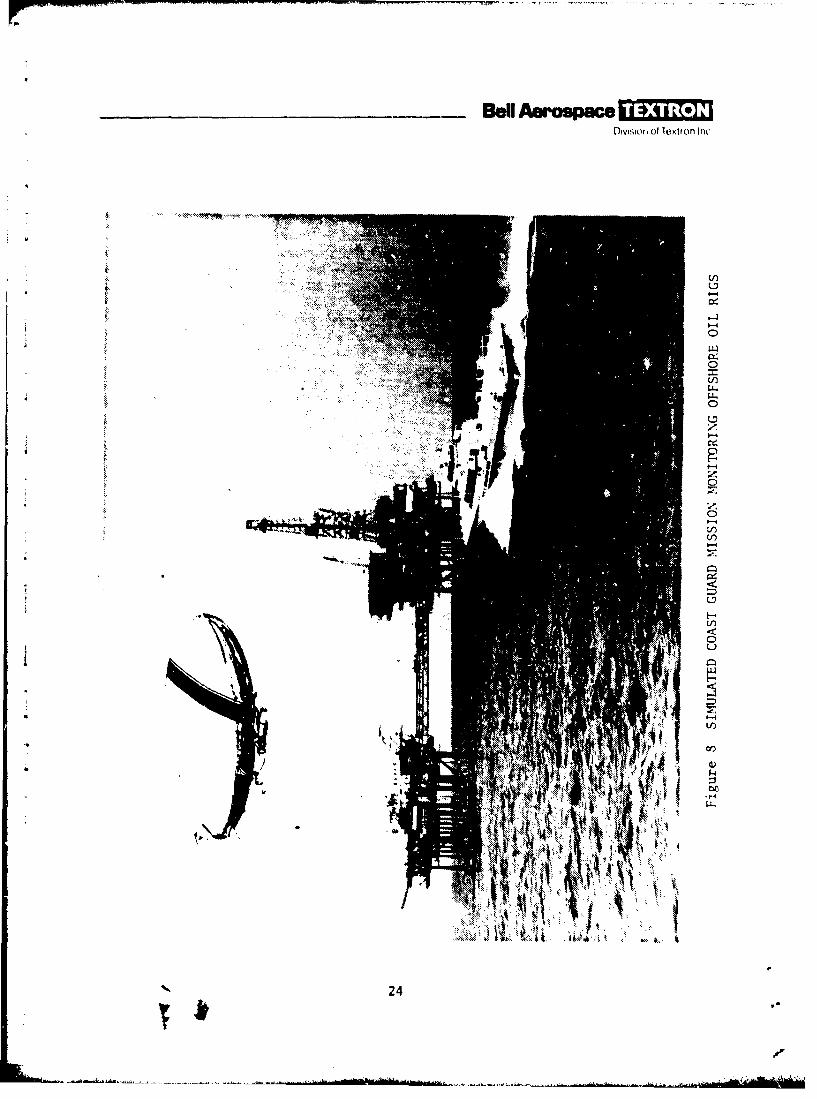
has been used. The angle of attack is reduced to maintain equilibrium, becomingapproximately zero at neutral buoyancy, and is made negative to provide negativedynamic lift as the MPA becomes lighter than air. If necessary (eg, at lowspeed), the rotors can be given a tilt to provide a downward component of thrust.Maximum forward speed is obtained when the airship is neutrally buoyant and therotor thrust is parallel to the axis of the airship. A typical Coast Guardmission is simulated in figure 8 monitoring an offshore oil rig.
With its long endurance, range, field of view, and relatively high-speed capa-bility, the airship can maintain station, detect, overtake, and board eventhe fastest of surface craft such as the Bell-Halter 110-foot SES shown in the
figure.
Landing is the reverse of takeoff. Negative thrust is used when the airship islight, and a lateral component of this thrust counteracts wiiud during hover andlanding. It is also used for ground-taxi control. After taxiing to the mooringmast area, the airship, using its automatic mooring capability, drives its .nose extension into the mooring cone, simultaneously engaging the ground-tetherhookup fitting on the landing gear to a circular track tether attachment. Wateror other ballast would be used for mooring in lieu of this automatic mooringsystem.
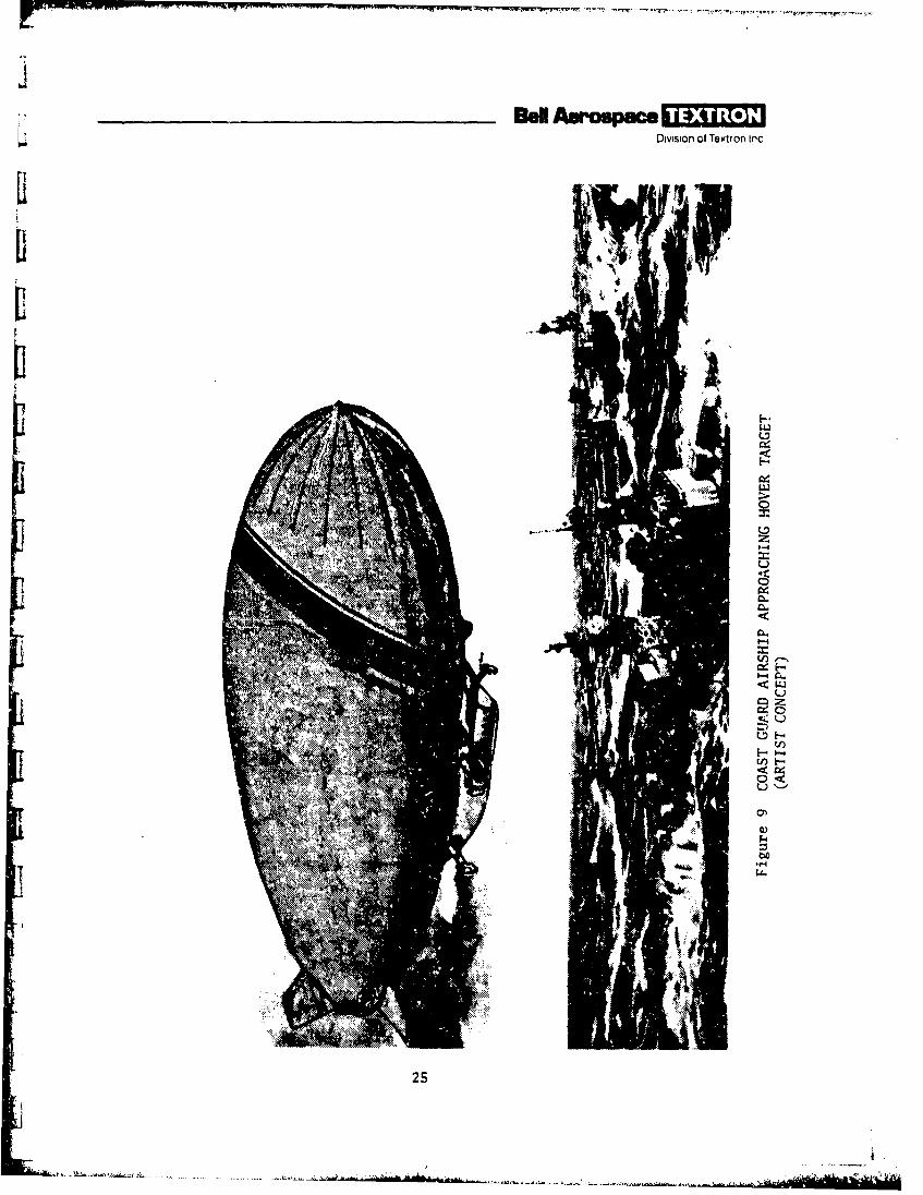
In some cases, a landing may not be desirable or even possible. Figuie 9 showsan airship approaching its hover target. A hovering maneuver may bb the onlyway to provide the emergency assistance to ships in rough seas as can be seenin the figure. In hover, as shown from a cockpit view in figure 10, the airshipaligns itself into the wind and the Bell quad-rotor propulsion system providesthe significant improvements in power and control that will permit airshipsto have many practical Coast Guard applications in even the most adverseweather conditions. When hovering over its target, the airship can lower andretrieve a service module to and from the deck of a ship.
DESIGN APPROACH
As previously mentioned, when considering the previous list of operationalrequirements, it is clear that most of them can be generally satisfied byconventional, previously existing, nonrigid airships without the benefit ofvectorable and reversibls thrust. This provides a high level of confidencein the development capability of such a vehicle. However, because it lacks bothpower and power vector control, the conventional airship cannot fully achievethe zontrollability required for hover and VTOL operation. The conventionalairship is able to hover only by heading into a stea4y wind of no less thanabout 20 knots, and it is difficult to control laterally in variable windsor if the winds subside.
23
___ __ ___ _-BWIl As ospe 0~1Dson, ofllcxto nc
I-4
0
w
A0
24-
__________Bell Awopace -*Division of Textron Inc
0
1-4:
-4
........... .. . . .. .
tA25

I.
_________ _________- Bell ~ros~ ace jj~i~j6
II
H
-1,
H
b1.4I0
j H
C
"4b-I
S-1
C'UIIn
I ~1.
i U)
IA.
-V.-
DivsIon of Textron Inc.
Any airship gets lighter as it flies because it is using fuel. To maintain
~ j vertical equilibrium, a conventional airship can compensate in three ways:
a. By picking up water ballast (where possible)
ic b. By flying the airship at a decreasing positive angle of attack toreduce dynamic lift, or by flying at increasing negative angles of attack
C. By valving lifting gas (which is very undesirable).
In light winds during hover or at low speeds, very little dynamic lift would beavailable to the conventional airship. To compensate for fuel burned duringhover, ballast would have to be picked up continuously. An alternative solutionI~i 1.to this in the poast has been the recovery of water from the engine exhaust gases;however, the recovery equipment is heavy and also creates drag.1* i:Now if a rotor delivering vertically upward thrust is introduced, the situationis improved. By varying the thrust to match the heaviness of the airship, verti-cal equilibrium can be maintained. If the airship is light, ballast or adownward component of thrust is needed for equilibrium. Reversible thrust is,L therefore, considered essential for precision hover. However, lateral andlongitudinal components of thrust must also be avail-able to resist the w.,ndIi ~ and gusts from any direction. Since these lateral componentE are produced bytilting the thrust vector, they are not independent of the vertical balanceof forces. It follows that lateral equilibrium depends on the existence ofa significant vertical component that depends on the heaviness or lightness1. of the airship, as well as gusting, when it reaches the hover point. This inturn depends on the amount of fuel consumed before the airship arrives at thehover point. If the mission requires transfer of personnel or equipmentduring hover, the vertical-thrust requirement is further complicated. Clearly,a vertical-thrust component must be available in either direction (up or down),depending on the situation, and at or near neutral buoyancy up and down thrustcomponents of diagonally opposite rotors may be required simultaneously tomaintain vertical equilibrium while developing lateral thrust. Even withthis capability, further vertical, lateral, and longitudinal thrust variations
are needed to compensate for gusting, which car. come from any direction.Large angular movements of a propeller or rotor are often impractical becauseof the high accelerations and gyroscopic forces which may be generated; this
T limits the usefulness of swiveling propellers or rotors. The Bell reversible-thrust quad-rotor concept solves these problems. Reversible-pitch propellersor rotors minimize the required angular tilting of the rotor plane, and withfour rotors, lateral thrust near neutral buoyancy can be obtained by directingthe thrust of the two diagonally Opposite pairs of rotors in opposite(primarily vertical) directions. With only two rotors, this technique willresult in an undesirable roll; in fact, equilibrium is possible only becauseof the natural pendulum stability of an airship.
27
.............-.... *. - ...
-ti7. Divin of Textron Inc
L There are other solutions to this problem, but they appear to be less desirable.For example, the negative-thrust requirement can be avoided by designing theMPA to fly heavier-than-air at all times, avoiding neutral buoyancy and using
L vertical rotor lift to stay aloft at low speeds, and dynamic lift from thehull at high speeds. This is possibly feasible for small payloads and fuelloads but would become very inefficient at large values as shown in the Jparametric tradeoff study (section 4). Alternatively, to minimize theheaviness of the MPA design, ballast would be required as payload was
removed or fuel consumed. In this case, one of the desirable features, noL. Iballast transfer, would be sacrificed. In addition, with the heavy-airshipconcept, the negative lift is not available to augment ground handling withan added downward force on the landing gear, as in the reversible-thrust
[ concept.
In the case of an inadvertent engine failure, the quad-rotor reversible-thrustdesign has another advantage. If it occurs when the airship is heavy, not asmuch payload would have to be aborted since its lift is only partially dependenton rotor thrust. If the engine failure occurs when the airship is light, ithas the advantage of abundant time to vent helium to achieve vertical equilibrium.At intermediate payloads engine failure should be less of a problem since theairship is usually closer to neutral buoyancy.
Oversized ballonets would be provided to handle the emergency condition wherehelium must be vented. The ballonets are not large weight items and willprovide greater altitude capability with proportionally smaller payloads for
L high-altitude missions.
An advantage is seen, therefore, in using four rotors with reversible thrust,symetrically located with respect to the center of buoyant lift, to minimizeroll moments otherwise expected with the power levels required for the subjectmissions. The control available with quad-rotor reversible thrust enablesthe MPA to hover over a stationary surface ship, or one moving in any direc-
rtion, and to respond to changes in wind direction without having to changethe heading of the airship. The concept also eliminates or minimizes the needfor ballast transfer during a mission because it normally flies closer toxueutral buoyancy, permits the airship to fly at a smaller angle of attack andto use less power and fuel in most situations (see section 4), and providesimproved ground handling.
rFor reasons of accessibility during maintenance and repair, it does not appeardesirable to locate the rotors at the elevation of the aerodynamic center ofpressure in crosswinds. Since they will be lower, a small roll moment may begenerated which can be balanced by the natural pendulum stability of theairship in roll.
[ 28
I.

_____ Awa espucOivision of T*e,1ron Inc.
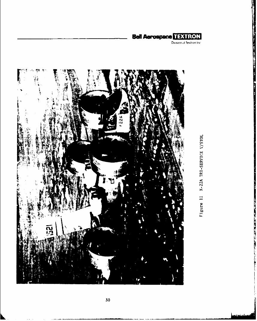
Preliminary examination of the thrust requirements for the coastal patrolapplication suggests that the maximum thrust is normally required in theforward direction (although definition of lateral-thrust requirements mayalter this initial expectation). To provide hover capability for VTOL andsurface vessel boarding operations, a full 90-degree swivel of the rotor thrustin the pitch plane is then equired. This is generally within the currentstate of the art as demonstrated by existing Bell multidirectional thrustaircraft including the XV-3 convertiplane VTOL, the twin-jet X-14 VTOL, theX-22A tr-service V/STOL, and the current NASA/Army XV-15 tilt-rotor aircraft.The XV-3 and X-14 can be found in appendix A, and the X-22A and XV-1S are shownin figures 11 and 2, respectively.
Another significant feature affecting the MPA configuration is the abilityto land at sea (figure 5), if required. Several ways of doing this areconceivable. If the airship is slightly heavy, simple bag floats on the car,for example, are relatively light and simple but may require auxiliary devicesto provide sufficient rolling and pitching stability. Floats near the bow andstern, and under the propulsion units (which must be well outboard because ofenvelope interference effects) are also possible. Heaving of individual floatsin waves can be alleviated by making them extend vertically into the water,like spar buoys, to a depth where wave disturbances are relatively small(wave amplitudes diminish exponentially with depth). Design of such verticalfloats, whether a hinged and/or extendable rigid type, or an inflatable fabrictype filled partially with air and ballasted with water for stability anddepth, initially appear attractive but may be somewhat heavy or complex comparedto other approaches.
In addition to axial loads, they must withstand bending moments from thelateral forces exerted by the waves, and from water drag resistance to windforces on the airship.
Because of its light weight and design simplicity, the float configurationcurrently selected for the MPA employs a combination of sea anchors andfloats. In a normal heavy mode of operation, four flotation bags would extendfrom the fore and aft sections of the car. The sea anchors would be deployedfrom fore and aft locations on the envelope. In this way flotation isprovided by the flotation bags, and stability is provided by the sea anchors.
In a normal light mode of operation, the flotation bags are not necessary andthe airship would essentially be anchored in the desired position with thewinching of the sea anchors providing the capability of vertically positioningthe MPA. If weathervaning is desired, the airship would have to be ballastedfor vertical equilibrium and moored only with a nose anchor.
29
in 'r-r-
_ _ _ _ _ _ _ _ _ _ As aw spac.Division of Textron Int
IL
"4k
rur
30
_ _ _ _ _ __ _ _ _ 8d Am oupmc 11fiDivision of Textron Inc.
Another operational variation of this concept, when the airship is heavy, wouldbe to use the anchors together with positive thrust on the rotors. Near thesurface of the water, the sea anchors are dropped and filled with water tohold the MPA down against the positive rotor thrust. In this way, the airshipeasily holds its position without the degree of pilot control required fornormal hovering. The sea anchors also provide drag resistance to wind forces.Since the airflow is directed downward and the engine location is high, thereshould be little danger of water ingestion into the engines. Though fuelconsumption may not be minimal, this use of sea anchors may be an excellentalternative to landing on rough water or trying to hover in gusty winds.
SUBSYSTEM DESIGN TRADEOFFS
Several subsystem design tradeoffs were made and, although further study isneeded to establish the final design, the results of these tradeoffs were usedin the computer and the simplified manual airship sizing analyses. These sub-system tradeoffs included some state-of-the-art survey and some analysis togenerally configure the subsystems.
The envelope slenderness ratio of about 4.5 is not necessarily optimum, andshould be the subject of more detailed design study. The X-tail shown wasfound to provide the greatest stability in yaw, the smallest minimum turningradius, the ability to execute a 360-degree turn in the smallest amount oftime, and the smallest power requirements of any of several tail configurationstested.2 Similarly, the quad-rotor airship does have controllability withoutany tail at all, thus these advantages are not as significant as in a conven-tional airship. Other tail design considerations are that the larger thetail area, the more responsive it is to a crosswind gust during hover, andthat possible wet snow accumulation on the tail may hamper operation of thecontrol surfaces.
Test results from reference 2 indicated that the inverted Y-tail was comparableto the X-tail except that it did not turn the model as well. The invertedY-tail would be superior to the X-tail as regards the danger of snow accumu-lation, but the X-tail appears to present less area for a crosswind gust tostrike. However, in view of the comparable yaw stabilities, this differenceis probably more apparent than real. Within the limits of the present study,the X-tail assumed seems as good as any; however, additional investigationwill eventually be needed.
2Albert Strumpf, An AnaZysie of the Turning Charaoterietios of the XZP AirohipBased VPon UIndem ater, Forod-Turning Mod aL periments .(Stevens Institute ofTechnology, Report SIT-DL-S4-534, October 1954).
31
, .

Owvsmon of Textron Inc
A tricycle landing gear is shown, with the nose wheel under the pilot'scompartment and the main wheels mounted off the aft engine outriggers. Thelatter are mounted inboard of the engines to avoid interference with thepropulsion system, which must tilt, and are to be located to minimize outriggerbending moments while providing adequate roll stability. Roll stability onthe ground is probably not an important consideration in locating the landinggear, however, since it can be provided by controlling vertical-thrustcomponents, and has not been a problem with conventional airships on themast.
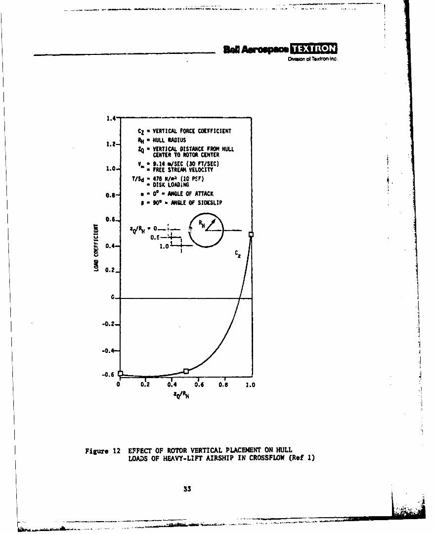
The location of the rotors with respect to the envelope is a design parameterof considerable importance. Reference 1 includes some information of thistype for a heavy-lift configuration with relatively large-diameter rotors incrossflow (figure 12). No data without crossflow is reported, and the resultscannot be used without reservation. Negative values of CZ in figure 12 indi-cate upward forces on the hull, and positive values downward forces. Achange of 1.0 in CZ corresponds approximately to the thrust of one rotor. Therotor thrust is always upward in figure 12, thus the aerodynamically best!ocation for the rotors is in the upper part of the bottom half of the envelope,assumling that the same trend holds for other conditions than the 30-ft/seccrosswind for which figure 12 was obtained (reference 1).
Structurally, there are significant disadvantages in having the rotors placedso high. Unless some type F ring structure is used, the rotor supportstructure length is extended with an obvious increase in bending moment andweight. If the main landing gear is supported fron the aft outrigger booms,the landing gear length, and consequently its weight, gre increased.
With a tilt-rotor configuration such as that in figure 1, the centers of therotors move upward as the propulsion units are rotated into the vertical-thrust attitude. A reasonable configuration is arrived et in figure 1 wherethe center of the rotors is approximately on a line 30 degrees below ahorizontal axis through the envelope centerline and is, therefore, within theoptimum zone indicated by figure 12. A preliminary analysis has indicateethat a support such as is shown in figure I would be lighter than a completering supporting the outriggers and nacelles. However, a spoked ring has yetto be analyzed and might prove to be lighter. Structural rings in a pressureairship envelope may also have other advantages and disadvantages. Forexample, the cross section of a pressure airship is not truly circular, andin fact varies as a function of the envelope pressure and the loading. Thering would thus be subjected to loadings that would not exist if the ringvere not there, and structural inefficiency must result. Further, the localloads on the onvotlnpe are undesirable both structurally and, probably, aero-dynamically.
32
.'-.- . ° '.
DMsion of Textron Inc
1.4-
CZ a VERTICAL FORCE COEFFICIENT
1.2- R - HULL RADIUS
Zq - VERTICAL DISTANCE FROM HULLCENTER TO ROTOR CENTER
Va 9.14 rn/SEC (30 FTISEC)1 FREE STREAM VELOCITY
T/Sd " 478 N/ok. (10 PSF)a DISK LOADiNG
0. - 0 ANGLE OF ATTACK
1 " 900 ANGLE OF SIDESLIP
0.6.
RQ/Rf RN
SC
-J0.2_
0-.
-0.2 3
-0.,-
-0.6
0 0.2 0.4 0. 6 0.8 1.0
Figure 12 EFFECT OF ROTOR VERTICAL PLACEMENT ON HULLLOADS OF HEAVY-LIFT AIRSHIP IN CROSSFLOW (Ref 1)
33
O~ ol Textron Inc
The lateral position of the propulsion units is another variable of interest.Data presented in reference I indicates that, aerodynamically, the smallerthe rotor clearance, the better. The minimum tip clearance tested was 0.43times th, rotor radius. Minimizing tip clearance also minimizes structuralweight.
Nose mooring is assumed with an aft gear tie-down on a circular weathervaningtrack. Otherwise water ballast would be used for mooring where a circulartrack is not available.
Floats and/or sea anchors will be provided to give the MPA the ability toland on the sea near a surface craft for ease of boarding for inspection,or for assistance in emergency.
In addition, for the selected prototype design configuration, it was decidedthat the best initial prototype NPA point design should be configured with acurrent existing propulsion system to avoid a long and expensive propulsionsystem development program. Two Bell VTOL craft propulsion systems, theX-22A and the XV-lS (Bell Model 301), have been considered in particular(see appendix C). These systems represent the state of the art in tiltable,turboprop propulsion (see appendix D for Model 301 data). However, thecomputer parametric designs all used an ideal (rubberized) propulsion system,sized to ia.L each specific mission profile, to facilitate choice of a finalvehicle and aission capability for a point design.
4
34 '4
Ommion of Textron Inc
4. PARAMETRIC SIZE, WEIGHT, AND PERFORMANCE TRADEOFFS
As the mission definitions developed during the course of the program, itbecame apparent that the requirements of the various missions differed greatly,and led to a different MPA size for each mission. Although a fleet of eightdifferent-size airships would be impractical, sizing an airship for each missionfacilitates the evaluation of the cost of an airship to perform one, several,or all of the missions, according to priority.
Two methods were used for sizing the different airship configurations. Onewas a simplified manual design approach, and the other was a more complexcomputer design approach. The manual approach was first used to configuredesigns for the various missions. However, it quickly became evident thatadditional parameters would have to be traded off concurrently to be ableto reflect a design sizing optimization. An initial attempt was made to usethe CASCOMP program (developed by Boeing Vertol and modified by NASA) using asubsystem weight estimating relationship. 3 However, after reviewing the program,a number of program simplifications to make the program more adaptable for aparametric-tradeoff and sizing-optimization study were suggested. Moreover,not having a fully working program and being unfamiliar with the CASCOMPprogram development, it would be easier for Bell to develop an airship designprogram having sizing and performance as its primary objective. Also, sincethe Navy would be using CASCOMP, the Bell program could be used as a checkon both the Bell manual airship designs and the Navy CASCOMP designs. There-fore, although the development of an airship sizing and performance computerprogram was beyond the scope of the current study program, it was decided todevelop the program with company discretionary funds and, if the developmentwas timely, the program could then be used to compare and enhance the manualairship design results. In retrospect, the computer program obviously becamevery useful since it yielded much more comprehensive parametric results.Therefore, because of its ability to quickly investigate many variations ofthe airship design parameters, the computer results are used for the primaryparametric comparison of MPA point designs. In spite of its obvious limita-tions, the simplified design approach provides a useful independent check onthe computer results and a convenient means of investigating aspects not coveredby the computer program.
There are certain basic differences in the two approaches, the most importantof which is that the simplified design approach develops configuations aroundone specific currently available power plant for all eight missions, so thatthe results are off-optimum. On the other hand, the computer program assumesthe optimum engine to be available for each point design.
S3 evelopmnt of Weight Estimating ReZationshipa for Rigid and Non-Rigid HeavyLift Airships (Goodyear Aerospace Corporation, NASA CR-IS1976, March 1977).
3S

Therefore, since the computer approach has been used for the primary 1PAcomparison and evaluation, it is presented in the following paragraphs. Forreference, the simplified manual design approach is presented in appendix G,together with a discussion on the comparison between the manual and computerdesign results.
The computer design program was developed so that the many variables affectingthe MPA designs could be easily examined parametrically to determine optimumvehicle sizes, weight, and performance for the maritime patrol airship missions.
With a minimum of functional and debugging difficulties, the MPA computer 4program was developed to design any airship for any hover, tow, and flightLonditions for any selected mission. The program operates by inputting rotorthrust to size the subsystems for hover, tow, and flight; it then iteratesuntil the thrust level is achieved to meet all three conditions.
The primary features of the program are that it:
a. Designs airships of any buoyancy ratio
b. Designs for any amount of positive or reversible propulsive thrust
c. Uses modified CASCOMP subsystem weight equations
d. Adds fuel system tankage and empennage to above subsystem weights
e. Also adds extra car, air conditioning, and furnishings for added crew
f. Provides ballonet system for altitude capability
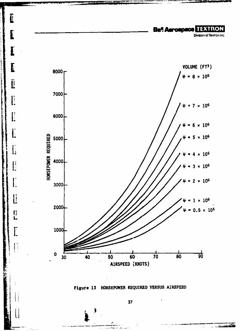
g. Provides propulsive thrust, horsepower, and weight as a function ofvelocity (based on historical data; see figure 13)
h. Provides positive and negative dynamic lift as function of angle ofattack (a)
i. Provides rotor lift and thrust as function of rotor tilt angle ($)
j. Provides flight performance as function of air density (P)
k. Derives airship lift and drag from previous existing airship data asfunction of envelope volume, horsepower, and speed
36
DIvIson of Textron Inc.
VOLUME (FT3)
- *8 x 10⁶
7000Ii 7000-7 x 10⁶
6000
-V *6 x 10⁶
c •5000 5 X 10⁶
in 34000 .~. 0
' L ! 3 1 106
" 37
L 1 X 10⁶
Fr 2000 0.5 X 10⁶
1000
0 30 40 50 60 70809
I, AIRSPEED (KNOTS)
ii Figure 13 HORSEPOWER REQUIRED VERSUS AIRSPEED
37
_ _ _ _ _ _ _ _ _ _ Sd tie]aDiviiion of Textron Inc.
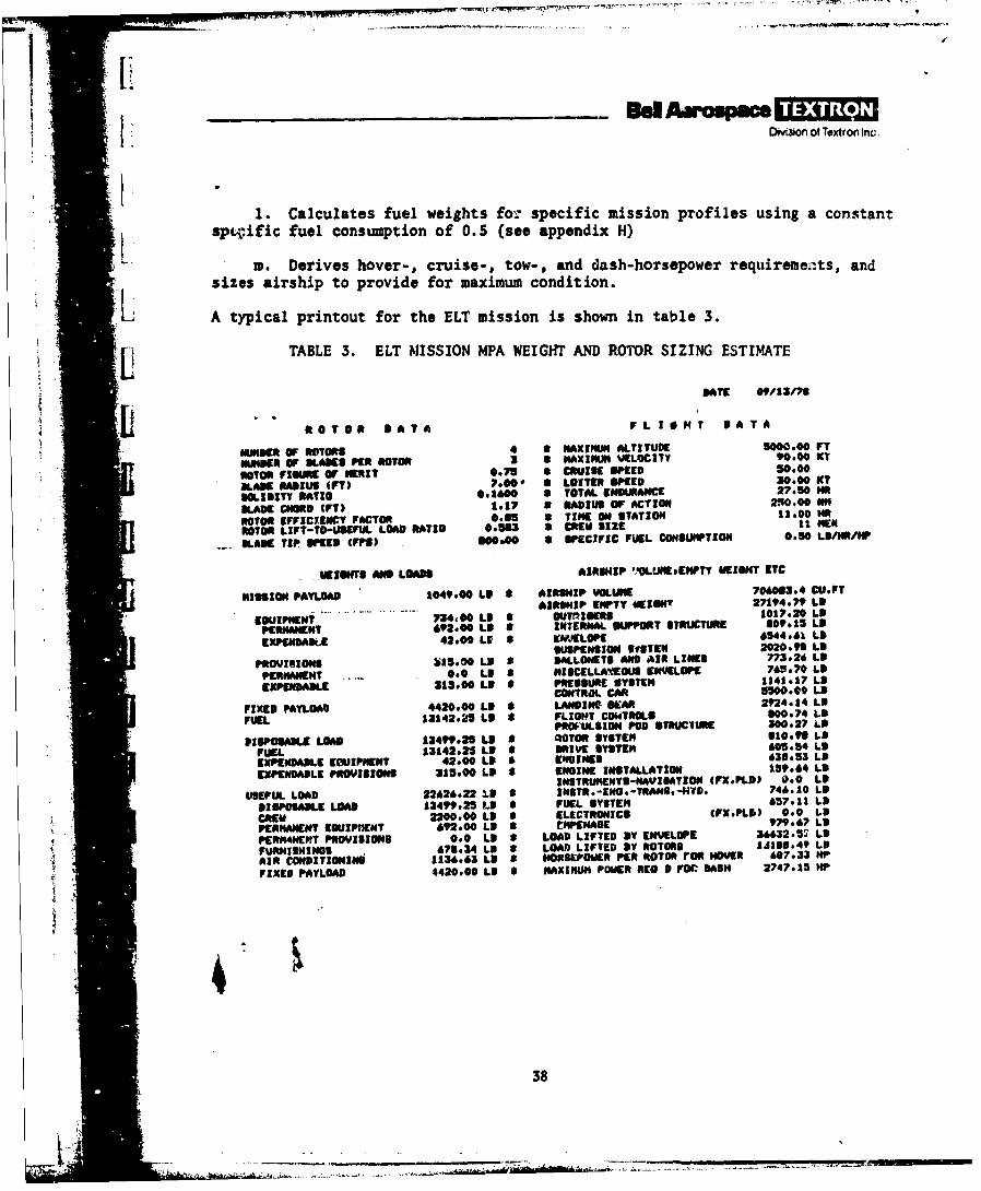
1. Calculates fuel weights for specific mission profiles using a constant* spWjific fuel consumption of 0.5 (see appendix H)
m. Derives hover-, cruise-, tow-, and dash-horsepower requirements, and
sizes airship to provide for maximum condition.
L A typical printout for the ELT mission is shown in table 3.
K [j TABLE 3. ELT MISSION MPA WEIGHT AND ROTOR SIZING ESTIMATE
DAT 09113/75
N OTO* DATA FLIOHT DATA
NUNDER or MOTORS 4 0 MAXIMUM ALTITUDE 5000.00 FT
"unDER oF SLAKS PE ROTOR 3 a MAXIMUM %ELOCITY 90.00 XT
ROTOR flowR of WERIT 0*75 * CRUISE WPEED 50.00
LAW RADIUS 4PT) P.00~ S LOITER SPEED 30.00 IX?
SOLIDITY RATIO set&"0 0 TOTAL EINDURNANCE 27.50 HiR
MLADE CHORD (FT) 1.17 a RADIUS OF ACTION 240.00 PH
ROTOR EFFICIENCY FACTOR 0.61 * TINE ON STATION 1100NROTOR LIFT-TO-USEFUL LOAD RATIO 0son * CREW size 1 E
SLADE TIP SWEED (FPS) 0000 * SPECIFIC FUEL CONSUMPTION 0.50 LSAIRIW
WEIGHT@ AND LOAN AIRSHIP "OLLJMEPIEHPTY UKI04T EITC
515810W PAYLOAD 1049.00 L9 0 AIRSHIP VOLUME 70&OS3.4 CU.FT- ......... AIRSHIP EPTY WEIGHT 27104.7 LU
EQUIPMENT 724400 LD 9 OUT!11IEs 1017.20 LDPIERNMENT 692.00 LS S INTERNAL SUPPOT STIRUCTURE 809.15 LIP
EXED~E42.00 LV S EIIJELOPE 6544*61 LIPSUSPENSION origTin 2020.95" LS
P*VUIN 15.O0 LN S AtLONETS AND ^IR LINES8 773.26 LU
PERIMANENT 0.0 LIP S NISCELLAVEOUS ENVELOPE 70.70 L9
EXPENDADLE 313.00 LD S PRESSURE SYSTEN 1141.17 LUCONTROL CAR 5500 LU
FIXED PAYLOAD 4420.00 LD S LTNDLN S0R002.74 L9FUEL 13142.25 L11 S FLIONT COWERL O.4L
PRO*AULS1ON PoD STRUCTURE 300.27 LN
plUPOSADLIF LOAD 13499.25 LU S RtOTOR SYSTEM 310.96 LNFUEL 13142.25 LU S DRIVE SYSTIEM 695.54 L9EXPENDADLE EGUIPMENT 42.00 LU 6 ENG0INES 63053 LU
EXPENDAP1LE PROVISIONS 311300 LIP S ENGINE INSTALLATION 15t.&4 L9INSTRUMENT2SNAVIOATION (FX.PLD) 0.0 LO
USEFUL LOAD 22426.22 U. S INSTRs-ENO-TRAN*.4YD* 746. 10 LU
DISPOSADL LoAD 13499.25 LU S FUEL SYYTEM 657.11 LU
CREW 2200.00 LU 8 ELECTRONICS (FXPIJ 0. LUPERMANENT EWUIPIEWT 692.00 LU S MPENAGE97.7L
PERANET ROVSIOS 0 L S LOAD LIFTED OY ENVELOPE 36632.52 L9FURNISHINGS 08S#34 LU S LOAR LIFTED DY ROTORS JB.9L
41AIR CONDITIONING 1136.61 LU * HORSEPOWER PER ROTOR rOR HOVER 697.33 WP
FIXES PAYLOAD 4420.00 LU * MAXIMUM POWER REO 9 FOC DASH 2747.15 HP
38
_ _ _ _ _ _ _ - d Aerospace£ .ivision of Textron Inc
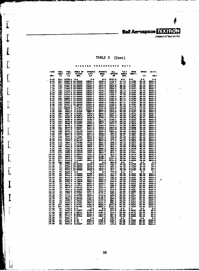
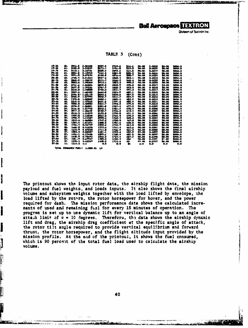
TABLE 3 (Cont)
1 3 3 of PIIFO fNAU C •ATa
VINE FUEL FUEL SMUI OF PYNA C 3TANWIC ALIL TILT once *9115 ,.TIT.33319 LEFT ATTACK LIFT on"5 COTM " OL CErf.
map. Lb LO DEG. Lb Lb NP Ka. KT. FELT
- .20 344, 32790.6 9.0 0.0 0.0 2749.3 0.M 0.0 0.0 0.00.50 209. 3271.3 30.00000 30330.6 4340.6 36702 .4 0.0730 50.00 3000.00.75 29. 12 04.2 10.00000 301130.6 4340.6 169.3 64 .32 00750 0.o0 3000.01.00 199. 3137.2 10.0000 1930.& 4340.6 1392.2 66.34 0.0719 30.00 1000.03.25 195 . is992.2 I0.00000 3130.6 4240.6 l19.5 60.3f 0.0750 30.00 3000.01.50 93. 3a500.9 a0 00 300.6 4340.6 3 10. 70.04 .0.750 1o.0 90003.75 500. S 3632.7 30.0 30530.6 4340.6 011 1.05.1 73:.13 00 50.0 S 000.02.00 365. 33427.2 1.00000 30530.6 4340. 3433.9 1. 3 .t00 30.00 1000.02.25 3. 113244.0 301.00000 10530.6 4340.6 IS&65.7 77.71 0.0710 1.0 1000.02.50 33. 11042.6 10.00000 30520.6 4340.2 3430.9 00.07 0.0710 10.00 100.02.75 100. 3032.7 0.0000 30530.6 4240.6 3429.2 3.43 0070 3000 3000.02.00 79. 30703.9 10.00000 10530.6 4340.6 1430.9 04.76 0.0750 10.00 3000.3.25 10. 30125.7 30.00000 10530.6 4340.6 3425.6 37.11 0.0753 30.00 000.03.50 11. 10347.7 30.00000 30530.6 4340.6 1423.4 10.46 0.0750 30.00 3000.03.75 14. 30174.0 9.3337 20394.0 4260.4 139.9 90.00 0.0736 30.00 1000.04.04 169. 1000114 9.61070 30220.2 4160.6 3340.0 ". 00 C6079 MOO 3000.04 25 164. 9041.& 9.43464 10051.6 4066.4 A310.2 90.00 0.0703 10.00 1090.04.50 119. 9602:4 9231529 9007.9 3977.3 3213.0 90.00 0.0697 30.00 1000.04.75 1 NS 91127.1 9.02300 9720.6 3092.6 139.6 90.00 0063 50.00 300.0
:100 . 976111 .216 973.7 312.2 127.4 .90 0.0693 30.00 $000.41.25 347. 9229.4 •.6393 9422.3 335:.6 1176:9 1.:00 0646 00 3 00.0
9. .14 344. 90593.40332 91. A6.. 343. 90to00 0133 3000 3000.1.75 140. 945.6 01.36"6 91352.3 393.4 320.3 9001 0 0.0621 30.00 1000.06.00 127. 00.019 8.15291 3992.0 352P.1 1094. 0 9.00 0*.610 10.00 1O*o.C6 25 134. ,75 1 7.99390 365.2 2463.9 1076.4 90.00 0.t99 30.00 1000.06.0 1231. 8544.3 7:1907 372,.4 2403.4 1047.0 9000 ::53 30 1000. 0675 13. 41,.2 .603531 051£.5 33,1 A024.3 to 00.00 0 50,00 1000.07.00 321. 62790.7 7.34190 0462.4 2290.0 1003.6 90.00 0O69 11.00 1000.07.25 1323, 0163. 7.,9903 3337:0 3236.9 913:. 90.00 00559 0.00 9000.07.30 321. 047.2 7.25973 3214,0 325.9 964.2 90 0.953 30.00 3000.07 5.15 I T: 79290 7:12311 8093. 3137.0 945.3 9.0 0 0.0142 30.00 1000.03.00 136. 7913.0 6"I13 V975.3 3090.0 91.2 19.00 0.0334 30.00 1000.03.2 114. 7699.3 6.64354 7N59. 2 2044,6 923.4 90.00 0.0526 119.00 300.08.30 11 2. ,137.3: 6:734l 7745.2 3003.3 09.3 .00 0.0319 0.00 3000.1.71 110. 7 *772 6*63304 7632.4 2959.4 41".4 90.00 0.*012 10.00 30009.00 Soo. 7269.0 6.469M 7523.4 2919.1 665.I t0.00 0.050 30.00 3000.09.3% 10. 7262.7 627330 7415.3 2080.3 050.9 90.04.0496 90.00 3000.O9.30 105. 7100 6.7553 7300.9 2042.3 337.2 90.00 0.0491 10.00 SM0. 09.71 103. 70s5.0 614143 7204.3 200.7 024£ 90.00 0.0484 30.00 1000.0
10.00 301. 6953.6 6.02994 7101.2 2731.0 113. 90.00 0.049 30.00 3000.0S0.25 100. 453.6 S.92062 6 99.1 2730.1 799.4 9".00 0.0473 30.00 3000.0'30 3:43. 6110.2 1.19050 6099.9 5720.7 3747.2 90.00 0.0306 90.00 *000.030.5 34. 6160.3 1.34634 65.5 1703.0 271.3 90.00 0.0304 90.00 3000.0
3 1 66552. 0.00 6.0 779.2 0.0 0.0 0.0 0.012. 50 3. 3579.2 4.37023 3700,9 3363.9 696.90 U6.03.049
£3.259 : 4.3396 346.13 2303.0 047.0 90.0 009 .0 100 0.0 2 4197 4.1 54.43 13, 2212. 6139 0OO 0.0392 10.00 9000.0341 0 : 7.493.4 31145 364.6 2202.4 610 90.00 0.0392 10.00 600.013.00 2. 17394.23048 7 t1 .4933.3 39 605. 90.00 0.03 Wo 600 00.0
:1.25 75. 7.4 4.169 403.6 236S.2 600.2 90.00 0.0374 00.00 1000.0,.0 70. 4,2 40. 3 4 460.9 247.i 14.9 90.00 0.033 30.00 3000.013.75 74. 46.3 2 42-6.2 233.. 60. 91.00 0.035 10.00 00 0013.50 7. 4492.3 2.4052 4642.& 3229. 6053. 9.00 . 4 40.032 0.00 5000. 0*6.25 7U. 42.0 .24*231 419.4 2304.9 190. 90.00 0.0300 10.00 00O.13.30 703. 4009.654 92357 4466.3 5 21, 647.3 90.00 0*.039 90.00 6000-036.75 70 6 ."590 4835.9 2313.3 6.20 90.00 6.037 90.00 300.0
I so.2 74 . • 4 40:6 :9164 106 U12 4 296 3 2, $04:9 00 ::37 930.' ,00 I0014,70 7? S9413 3.045 J6" 2 '12. 13:' of 9 S tGO O
' $0*00 S0O
17.00 ?3. .4i3.0 2.4211 42.S 119.0 49.2 00 0 .031 0.0 00
16.25 7:440. 6, 9.C219 41395.4 3102.0 339.3 90.04 0l.066 90.00 S69.0,s is+ .4 0. 91 66.3 051163. 1407.1 90.00 0.06 0.00 0.0
75 33: 3620.3 09.034 13. 27 33. 3 26 33.2 90.00 09.07 4.t 0.00 0Q.013.00 9. 3643.7 3.2 34 .6 3307.6 303. 9 . 00. 0.031 3.00 10.630.s 47. 3069.0 0.3509 4.0-2 8436.0 SM39s 0.0 0.0 0.0 60.0
3330 66. 34431.0 2.40 3333.0 39.1 01.7 90.00 *.0231 m0.00 000.018.75 3. 33.7 2.4 2. P407.3 13.0 t22t.6 90.00 0.0333 90.00 100019.00 61. 330. 2. 1639 •423.9 3919.7 W49.6 90.00 0.0232 90.00 1000.0
39
L 0 1 900000 , 0, . . , .A ,"
Wuhn of Atmon Inc.
TABLE 3 (Cont)
g9.3 64. 880: .,'U1 36. *8933 -1 .0 9a'l* 0.00 :.0337 of." 360.6V9O 6. I I3 M . I Nl M 3l 1 4: , 3 t1 .4:: , 0,": 30 .P , l I )"'" 61 MS a" 0.0I "a" we0' 0' '0i :I:,l:63, On3.* R.OM41 3 '. £V 6 M4.4 302.9 "0.Of 0.0323 30.6 9W0.0
CA IIM:112OW"912: 116666398 : 6 M 0.:038, SM.9 ft6S.049,00 3.38 3.0 ,60.
as."0 4. "6.94 M 36 0 44.6 84.9 4 6 90.40 0.039V 3U."0 OM0.0ft.7 6, 113.,68.3136 106. 1,36:. 463, 90.00 0038 .m 6602,0.0 60. 384 .4 104 , t: 4:9 009401 . 00 !9 0.03ll .60 3600.3
33.1: 00 * 1.0 8l;' *.3, 3 .I 8:79,.3'" .0, 90.0900 ,.030,' ,.0 3660.61310l 6. II 1,930 8.66 39 . 8 1 37l~.4 471.1 60.60 0.0309 60.60 360.0
35:9. , 136 43 . 2 . 3113.1 3730.3 47. 90.60 0.M4 30,00 3660.4'80335 "'01 IM 3"i1 P 71 4Me. H0 is00 1:*0 one
031% 0. 8643. a ,404" , ' 3 Ml 1, ,,. .7.6 90.0 0.0&00 30.0 600.031.3 36. ft 4* 8.06" A84 301. 1676 .4 440.3 90.M0 C00 0 3 ,00 0 0
313 U: 21"6.4 0.96;46 2642.4 £741.9 4M4. 90.0 0.MM 60.0 0 0.933.13 39. 's. a 3773.4 8148.4 4 a3.4 90.60 b.001 36.60 3606.08"41 Is: :u:: :zu 1": U:: "M
1496. 0.7443 3399. 8)34 4:0I 9.00 am 799 6.0 3 0.mft *3426 8,6W 193 143.3 I234.4 437A . 06 0.630390 .0 S *
137"16049 0.966 19,36.8 730.4 43. " M.,00 00o9f 3 0 30=6.0*lJ , 3 3 3. 8 0 34064 6 1- 8 * 4 .0 4 1 1 6 " 0 . 3 30 ., 0 3 0 .6• 0
VS.8" s 4. 0 67 00 .0 M6a 'I 0. 06 6.6
payload and fuel weight, and loads inputs. It also shows the I"inal airship
volume and subsystem weights together with the load liffted by envelope, ctheI load lifted by the rotrrs, the rotor horsepower for hover, and the powerrequired for dash. The mission performance data shows the calculated incre-mnts of used and remaining I~ for every IS minutes of operation. The
Maprogram is set up to use dynu4ic l .4 for verical balance up to an angle of
attack limit of * 10 d egrees. Thereforg, tbn data shows the airship dynciiclift and drag, the airship drag coefficient d the specfic angle of attack,the rotor tilt angl , requiaed to provide verical equs tbriu and faorwardthrust e the rotor horsepower, and the flight alti~ud input provided by themission profile. At the missof te rintou, it shows the fuel consu ed,
khich i 90 perc't o a the toal fue] load use to calculate the airship
volume.
[1 40
p _ _
= N v -_- ... r - =r 7 .a. ...... a -.- -- . . -- . . .. .. . ..... -.... . 4, . . o_
L
W Am A ampece1 .EloDvivuo of Textron Inc.
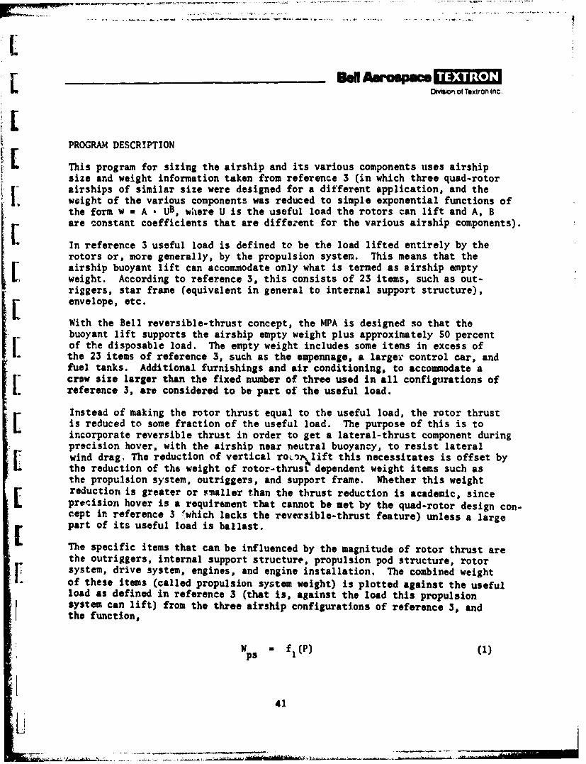
PROGRAM DESCRIPTION
This program for sizing the airship and its various components uses airshipsize and weight information taken from reference 3 (in which three quad-rotor
I airships of similar size were designed for a different application, and theweight of the various components was reduced to simple exponential functions ofthe form w a A • UB, where U is the useful load the rotors can lift and A, Bare constant coefficients that are different for the various airship components).
In reference 3 useful load is defined to be the load lifted entirely by therotors or, more generally, by the propulsion system. This means that therairship buoyant lift can accommodate only what is termed as airship emptyweight. According to reference 3, this consists of 23 items, such as out-riggers, star frame (equivalent in general to internal support structure),envelope, etc.
With the Bell reversible-thrust concept, the MPA is designed so that the- buoyant lift supports the airship empty weight plus approximately 50 percentI| of the disposable load. The empty weight includes some items in excess ofI. the 23 items of reference 3, such as the empennage, a larger control car, and
fuel tanks. Additional furnishings and air conditioning, to accommodate acrew size larger than the fixed number of three used in all configurations ofreference 3, are considered to be part of the useful load.
Instead of making the rotor thrust equal to the useful load, the rotor thrustis reduced to some fraction of the useful load. The purpose of this is toincorporate reversible thrust in order to get a lateral-thrust component duringprecision hover, with the airship near neutral buoyancy, to resist lateralwind drag, The reduction of vertical ro/_ilift this necessitates is offset bythe reduction of the weight of rotor-thrust dependent weight items such asthe propulsion system, outriggers, and support frame. Whether this weight
reduction is greater or smaller than the thrust reduction is academic, sincepre'ision hover is a requirement that cannot be met by the quad-rotor design con-cept in reference 3 rwhich lacks the reversible-thrust feature) unless a largepart of its useful load is ballast.
The specific items that can be influenced by the magnitude of rotor thrust arethe outriggers, internal support structure, propulsion pod structure, rotorsystem, drive system, engines, and engine installation, The combined weight
of these items (called propulsion system weight) is plotted against the usefulload as defined in reference 3 (that is, against the load this propulsionsystem can lift) from the three airship configurations of reference 3, andthe function,
W f ()
41
V
Dvwson of Textron Inc
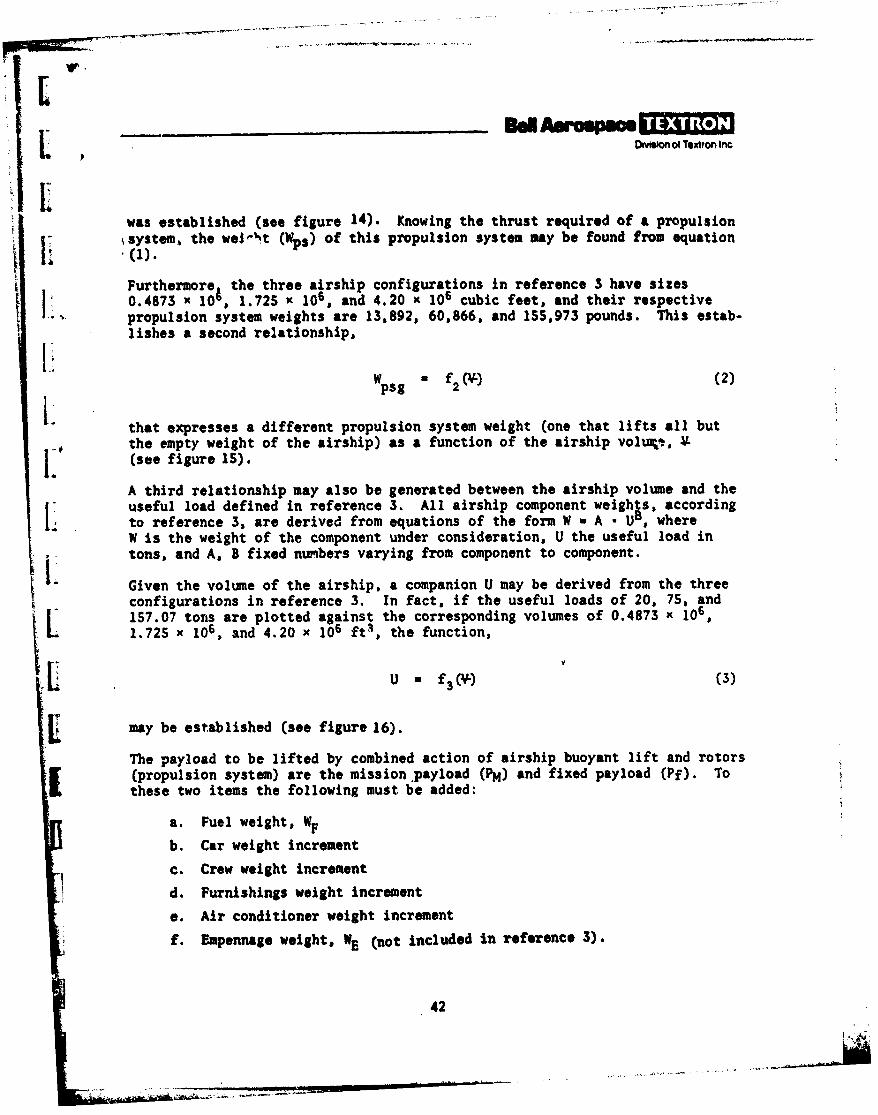
was established (see figure 14). Knowing the thrust required of a propulsion,system, the wel-"t (Wps) of this propulsion system may be found from equation
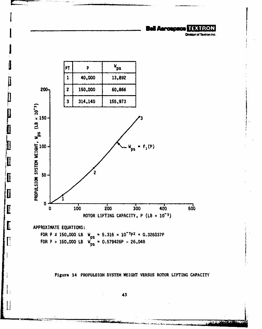
Furthermore the three airship configurations in reference 3 have sizes0.4873 x 104, 1.725 x 10⁶, and 4.20 x 10⁶ cubic feet, and their respectivepropulsion system weights are 13,892, 60,866, and 155,973 pounds. This estab-lishes a second relationship,13
Wpg f(-) (2)
that expresses a different propulsion system weight (one that lifts all butthe empty weight of the airship) as a function of the airship voluv. L(see figure 15).
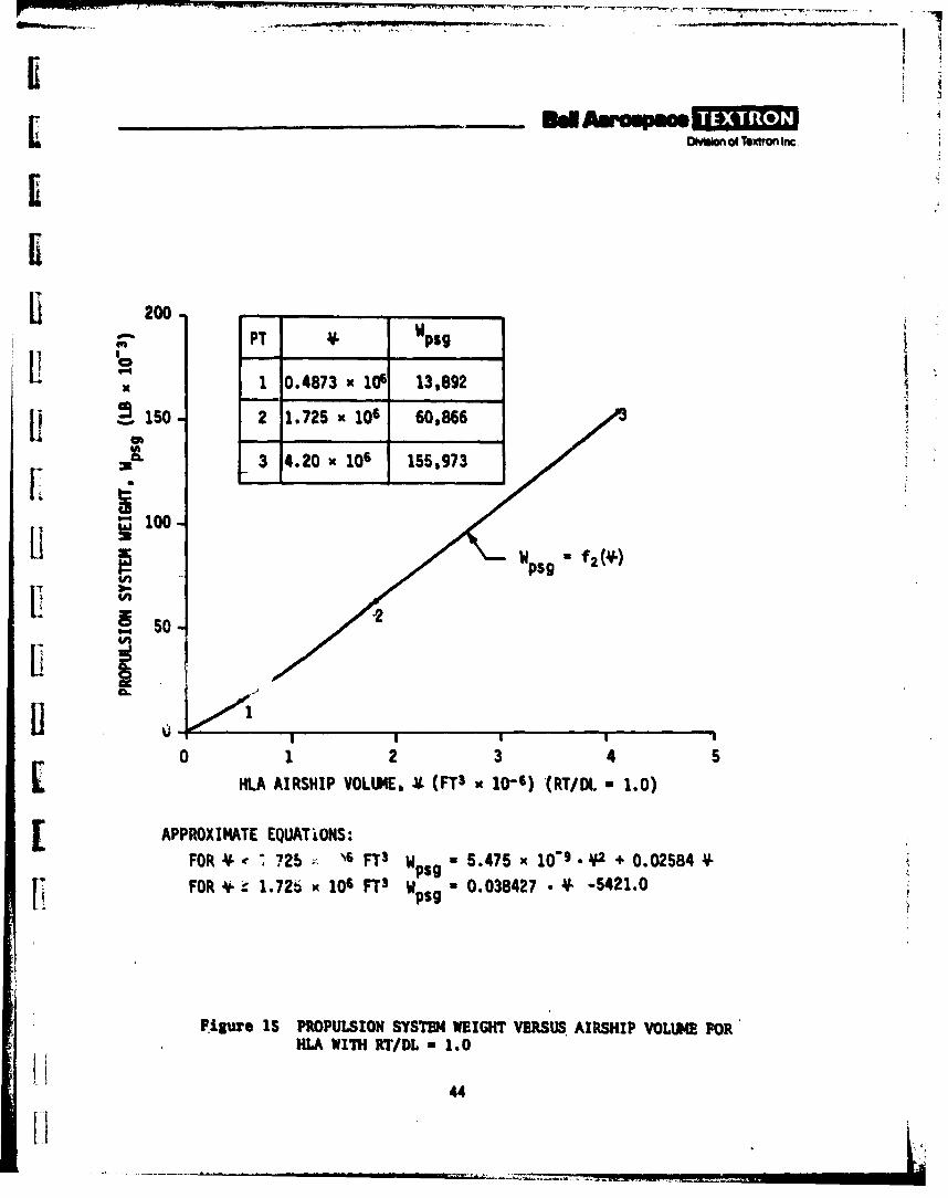
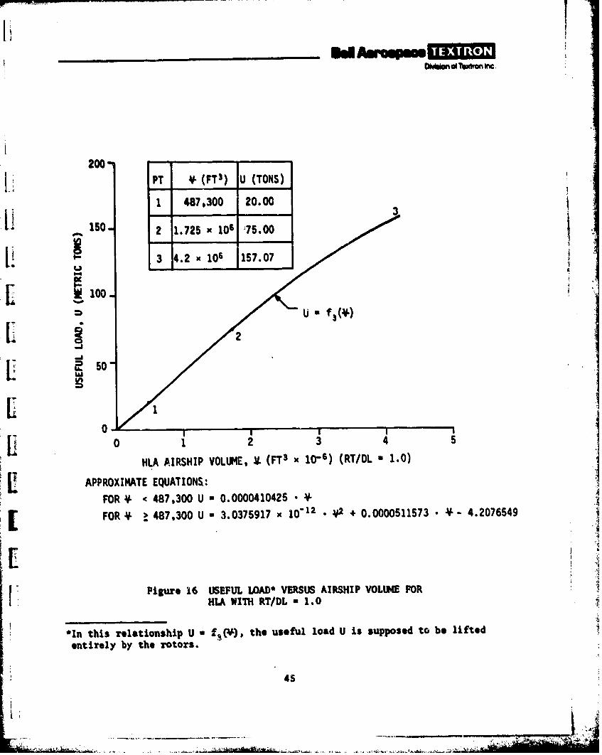
A third relationship may also be generated between the airship volume and theuseful load defined in reference 3. All airship component weights, accordingto reference 3, are derived from equations of the form W a A • UOB whereW is the weight of the component under consideration, U the useful load in
tons, and A, B fixed numbers varying from component to component.
Given the volume of the airship, a companion U may be derived from the three
configurations in reference 3. In fact, if the useful loads of 20, 75, and157.07 tons are plotted against the corresponding volumes of 0.4873 x 10⁶,
1.725 x 10⁶, and 4.20 x 106 ft3 , the function,
Y
U a f3 (*) (3)
may be established (see figure 16).
The payload to be lifted by combined action of airship buoyant lift and rotors(propulsion system) are the mission .payload (PM) and fixed payload (Pf). Tothese two items the following must be added:
a. Fuel weight, WF
b. Car weight increment
c. Crew weight increment
d. Furnishings weight increment
e. Air conditioner weight increment
f. Empennage weight, WE (not included in reference 3).
42
IrI OMIaomoTextron Inc.
I
PT P Wps
1 40,000 13,892
200" 2 150,000 60,866
3 314,140 155,973AIx 150- 3
0
-
'I 100- .p lP
ill. o
0 100 200 300 400 500ROTOR LIFTING CAPACITY, P (LB x 103)
E APPROXIMATE EQUATIONS:FOR P S 150,000 LB W - 5.316 x 10"7P2 + 0.326037P
PSFOR P > 150,000 LB W O 0.579426P - 26,048
Figure 14 PROPULSION SYSTEM WEIGHT VERSUS ROTOR LIFTING CAPACITY
1. 43
Ii
O~ano Texlta Inc
Ii
iiPT V- Wpsg
: 100.4873 x 10⁶ 13,892
. SO - 2 1.725 x 10⁶ 60,866
3 4.20 x 10⁶ 155,973
w+ f22 10
0 I23
HLA AIRSHIP VOLUME, V. (FT3 x 10-6) (RT/DL - 1.0)
[APPROXIMATE EQUATiONS:FOR * 725 )6 FT3 WPSg =5.475 x 10-9 *2 + 0.02584,
FOR * + 1.726 x 10⁶ FTS W . 0.038427 • ¥ -5421.0LI psg
Fiure 15 PROPULSION SYSTEM WEIGHT VERSUS. AIRSHIP VOLUME FOR'HLA WITH RT/DL - 1.0
44
.. . . . . .. .. . .. .. -I -'-C++. .. .+. ... .... . . .. ; :
LiI f
200-
PT ¥ (FTS) U (TONS)
1 487,300 20.00
1SO. 2 1.725 x 10⁶ :75.00
3 4.2 x 10⁶ 1 57.0
100-[ f
0II I
0 1 2 3 4 5
HLA AIRSHIP VOLUME, .t (FTS K 10-6) (RT/DL " 1.0)
APPROXIMATE EQUATIONS:
FOR < < 487,300 U * 0.0000410425 "
FOR V . 487,300 U * 3.0375917 x 1012 V ./2 + 0.0000511573 • V-- 4.2076549
I. ,
Pigure 16 USEFUL LOAD* VERSUS AIRSHIP VOLUIE FORHLA WITH RT/DL a 1.0
*In this relationship U a f,(f), the useful load U is supposed to be liftedentirely by the rotors.
4S
• ' __ ,, . t Ill IqC . . . ... .. A M " '
DmUOn of Textron Inc
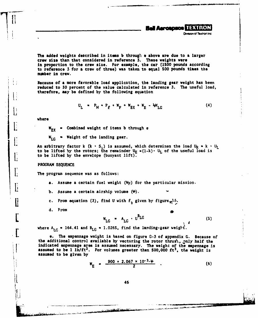
The added weights described in items b through e above are due to a largercrow size than that considered in reference 3. These weights werein proportion to the crew size. For example, the car (1SO0 pounds accordingto reference 3 for a crew of three) was taken to equal 500 pounds times thenumber in crew.
Because of a more favorable load application, the landing gear weight has beenreduced to 50 percent of the value calculated in reference 3. The useful load,therefore, may be defined by the following equation
UL PM PfWF WEX + WE "WLG
where
WEX a Combined weight of items b through e
W: LG a Weight of the landing gear.Li An arbitrary factor k (k • S ) is assumed, which determines the load UR k UL
to be lifted by the rotors; the remainder UE a(l-k)- UL of the useful load isi: to be lifted by the envelope (buoyant lift).
PROGRAM SEQUENCE
ii The program sequence was as follows:
a. Assume a certain fuel weight (WF) for the particular mission.
b. Assume a certain airship volume (v).
1c. From equation (3), find U with f, given by figureh5.
d. From ,= •GaAL UBLG (S)
where ALG ' 164.41 and BLG a 1.026S, find the landing-gear weig!t.
e. The empennage weight is based on figure G-3 of appendix G. Because ofthe additional control available by vectoring the rotor thrus%, .,nly half theindicated empennage area is assumed necessary. The weight of the empennage isassumed to be 1 lb/ft2 . For volumes greater than 500,000 ft3 , tfie weight isassumed to be given by
900 + 2.067 x 10⁻³.(W E 2 "(6)
S46
_j
Omhen of Textron Inc
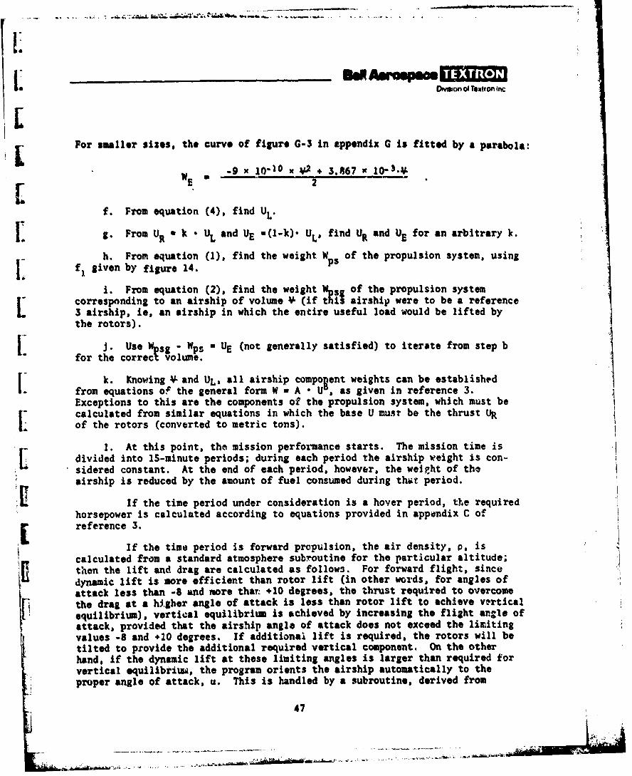
For smaller sizes. the curve of figure G-3 in appendix G is fitted by a parabola:
WE• -9 x 10- 10 X *+ 3.867 X l0-K.
f. From equation (4), find UL'
g. From UR a k * UL and UE -(l-k). UL, find UR and UE for an arbitrary k.
h. From equation (1), find the weight Wps of the propulsion system, usingf1 given by figure 14.
i. From equation (2), find the weight Wsg of the propulsion systemcorresponding to an airship of volume *f (if this airship were to be a reference3 airship, ie, an airship in which the entire useful load would be lifted bythe rotors).
j. Use sgo- WpSU-UE (not generally satisfied) to iterate from step bfor the Corrct Volume.
k. Knowing * and UL, all airship compo~ent weights can be establishedfrom equations of the general form W w A o U5, as given in reference 3.Exceptions to this are the components of the propulsion system, which must becalculated from similar equations in which the base U must be the thrust tRof the rotors (converted to metric tons).
1. At this point, the mission performance starts. The mission time isdivided into IS-minute periods; during each period the airship weight is con.
sidered constant. At the end of each period, however, the weight of theairship is reduced by the amount of fuel consumed during that period.
If the time period under consideration is a hover period, the requiredhorsepower is calculated according to equations provided in appendix C of[reference 3.
If the time period is forward propulsion, the air density, p, iscalculated from a standard atmosphere subroutine for the particular altitude;then the lift and drag are calculated as follows. For forward flight, sincedynamic lift is more efficient than rotor lift (in other words, for angles ofattack less than -8 and more thart +10 degrees, the thrust required to overcomethe drag at a higher angle of attack is less than rotor lift to achieve verticalequilibrium), vertical equilibrium is achieved by increasing the flight angle ofattack, provided that the airship angle of attack does not exceed the limitingvalues -8 and +20 degrees. If additional lift is required, the rotors will betilted to provide the additional required vertical component. On the otherhand, if the dynamic lift at these limiting angles is larger than required forvertical equilibtiuw, the program orients the airship automatically to theproper angle of attack, u. This is handled by a subroutine, derived from
47
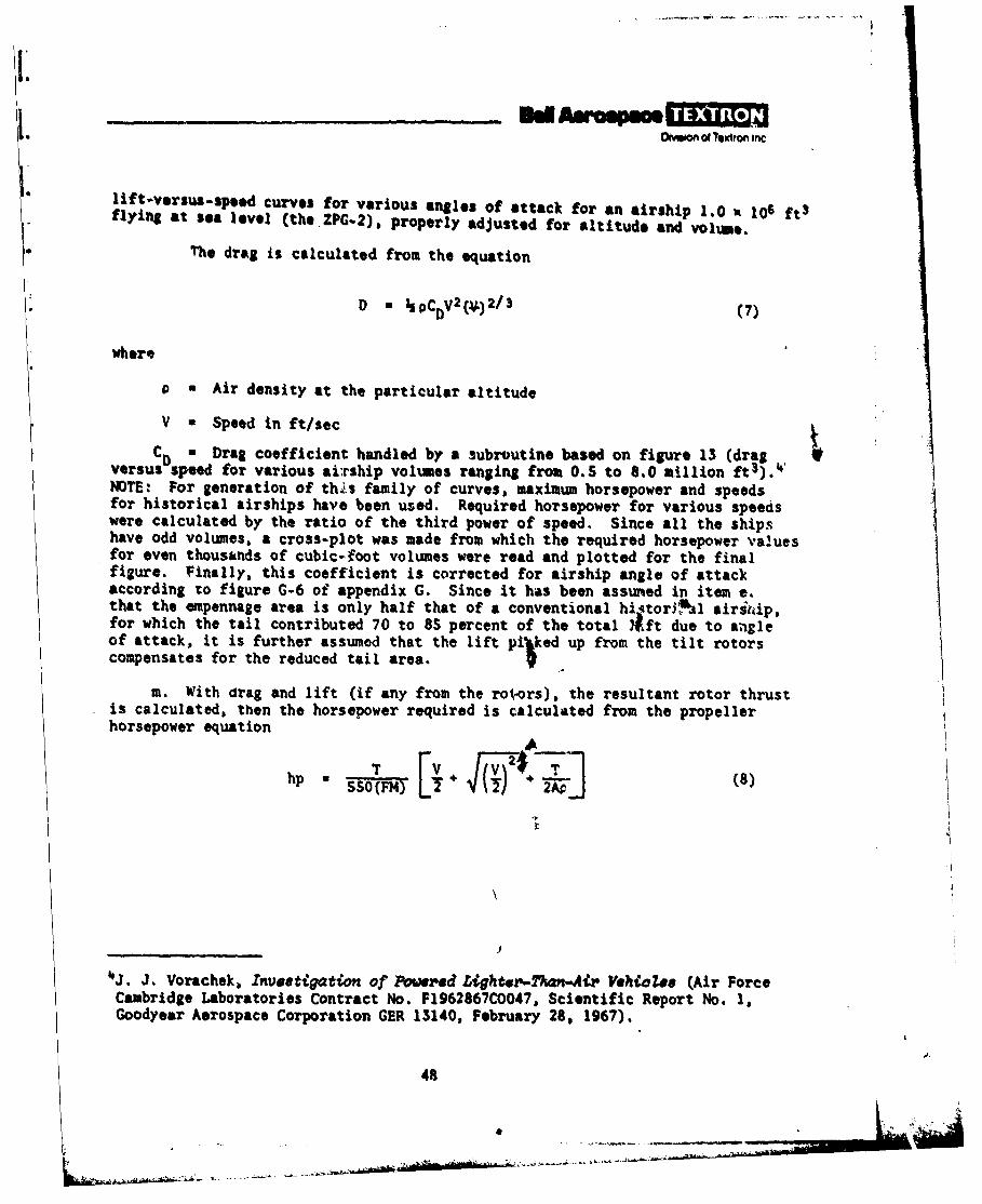
Dmnof Texon incSlift-versus-sped curves for various angles of attack for an airship 1.0 x 10⁶ ftS
flying at sea level (the .ZPG-2), properly adjusted for altitude and volume.
• The drag is calculated from the equation
* D w ho0c v2(*)2/3 (7)
* where
P a Air density at the particular altitude
V - Speed in ft/sec
CD " Drag coefficient handled by a subroutine based on figure 13 (dragversus speed for various ai:rship volumes ranging from 0.5 to 8.0 million ft3).4 'NOTE: For generation of th .s family of curves, maximum horsepower and speedsfor historical airships have been used. Required horsepower for various speedswere calculated by the ratio of the third power of speed. Since all the shipshave odd volumes, a cross-plot was made from which the required horsepower valuesfor even thousands of cubic-foot volumes were read and plotted for the finalfigure. Finally, this coefficient is corrected for airship angle of attackaccording to figure G-6 of appendix G. Since it has been assumed in item e.that the empennage area is only half that of a conventional hiqtor$ bAl airittip,for which the tail contributed 70 to 8S percent of the total 21ft due to augleof attack, it is further assumed that the lift pi'ked up from the tilt rotorscompensates for the reduced tail area.
m. With drag and lift (if any from the rotors), the resultant rotor thrustis calculated, then the horsepower required is calculated from the propellerhorsepower equation
hp 3SO(FM)(8
___________________ - I
4J. J. Vorachek, Inveatigation of Powrd Ughter-M -A' Vehaio7e (Air ForceCambridge Laboratories Contract No. F1962867CO047, Scientific Report No. 1,Goodyear Aerospace Corporation GER 13140, February 28, 1967),
48
* - . ~ TIL.~ -
- - - n . e.. . . -,.. . . ..... .. . ..
DMhbonofT.Etron Inc
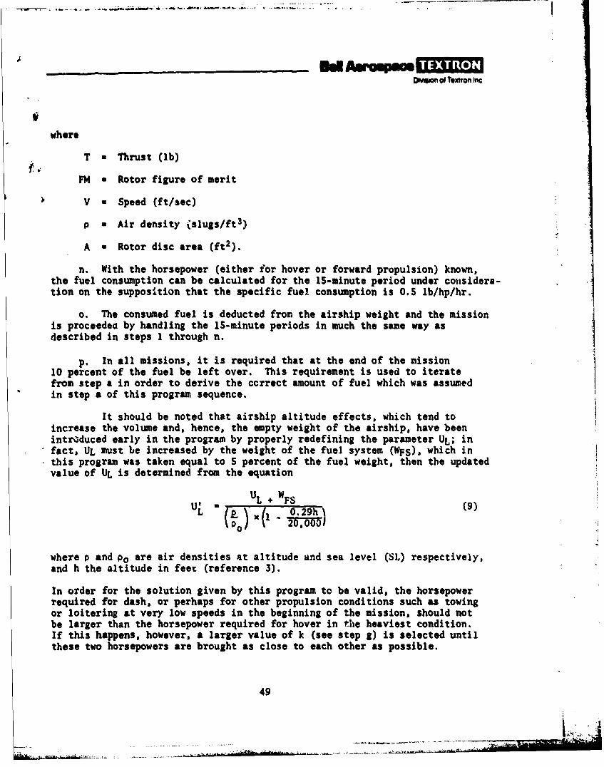
where
T • Thrust (ib)
FM a Rotor figure of merit
V a Speed (ft/sec)
P a Air density Cslugs/ft3)
A a Rotor disc area (ft2 ).
n. With the horsepower (either for hover or forward propulsion) known,the fuel consumption can be calculated for the 15-minute period under cousidera-tion on the supposition that the specific fuel consumption is 0.5 lb/hp/hr.
o. The consumed fuel is deducted from the airship weight and the missionis proceeded by handling the IS-minute periods in much the same way asdescribed in steps 1 through n.
p. In all missions, it is required that at the end of the mission10 percent of the fuel be left over. This requirement is used to iteratefrom step a in order to derive the correct amount of fuel which was assumedin step a of this program sequence.
It should be noted that airship altitude effects, which tend toincrease the volume and, hence, the apty weight of the airship, have beenintroduced early in the program by properly redefining the parameter UL; infact, UL must be increased by the weight of the fuel system (WFS), which inthis program was taken equal to S percent of the fuel weight, then the updatedvalue of UL is determined from the equation
U WUL + FS
where P and PO are air densities at altitude and sea level (SL) respectively,and h the altitude in feet (reference 3).
In order for the solution given by this program to be valid, the horsepowerrequired for dash, or perhaps for other propulsion conditions such as towingor loitering at very low speeds in the beginning of the mission, should notbe larger than the horsepower required for hover in the heaviest condition.If this happens, however, a larger value of k (see step g) is selected untilthese two horsepowers are brought as close to each other as possible.
49
_________ d Amow=pmOmw of Tomiton inc
COMPUTER DESIGN RESULTS
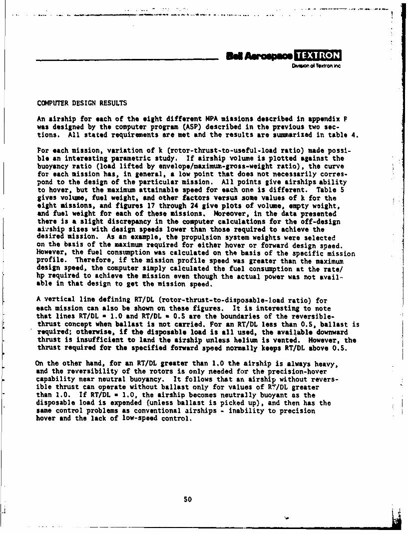
An airship for each of the eight different MPA missions described in appendix Fwas designed by the computer program (ASP) described in the previous two sec-tions. All stated requirements are met and the results are summarized in table 4.
For each mission, variation of k (rotor-thrust-to-useful-load ratio) made possi-ble an interesting parametric study. If airship volume is plotted against thebuoyancy ratio (load lifted by envelope/maximum-gross-weight ratio), the curvefor each mission has, in general, a low point that does not necessarily corres-pond to the design of the particular mission. All points give airships abilityto hover, but the maximum attainable speed for each one is different. Table 5gives volume, fuel weight, and other factors versus some values of k for theeight missions, and figures 17 through 24 give plots of volume, empty weight,and fuel weight for each of these missions. Moreover, in the data presentedthere is a slight discrepancy in the computer calculations for the off-designairship sizes with design speeds lower than those required to achieve thedesired mission. As an example, the propuksion system weights were selectedon the basis of the maximum required for either hover or forward design speed.However, the fuel consumption was calculated on the basis of the specific missionprofile. Therefore, if the mission profile speed was greater than the maximumdesign speed, the computer simply calculated the fuel consumption at the rate/hp required to achieve the mission even though the actual power was not avail-able in that design to get the mission speed.
A vertical line defining RT/DL (rotor-thrust-to-disposable-load ratio) foreach mission can also be shown on these figures. It is interesting to notethat lines RT/DL a 1.0 and RT/DL a 0.5 are the boundaries of the reversible-thrust concept when ballast is not carried. For an RT/DL less than 0.S, ballast isrequired; otherwise, if the disposable load is all used, the available downwardthrust is insufficient to land the airship unless helium is vented. However, thethrust required for the specified forward speed normally keeps RT/DL above O.S.
On the other hand, for an RT/DL greater than 1.0 the airship is always heavy,and the reversibility of the rotors is only needed for the precision-hovercapability near neutral buoyancy. It follows that an airship without revers-ible thrust can operate without ballast only for values of R"/DL greaterthan 1.0. If RT/DL a 1.0, the airship becomes neutrally buoyant as thedisposable load is expended (unless ballast is picked up), and then has thesame control problems as conventional airships - inability to precisionhover and the lack of low-speed control.
50
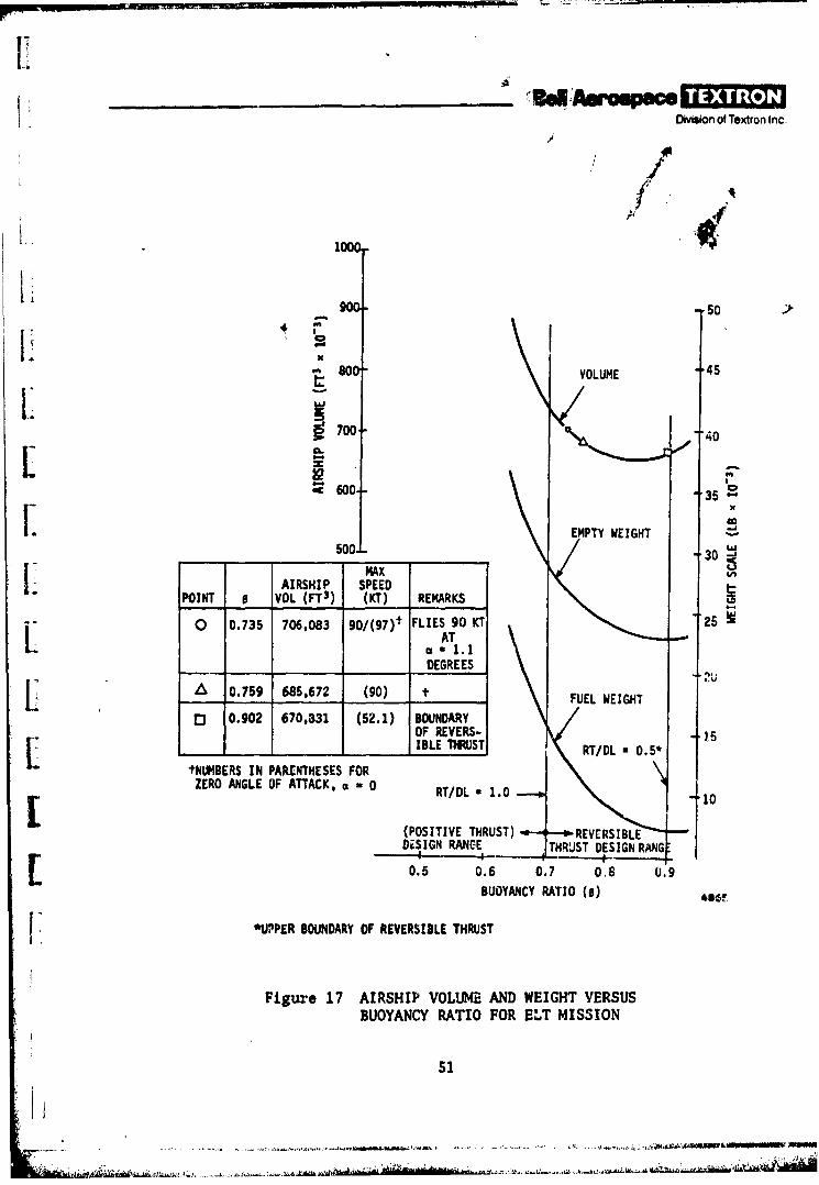
________ 3daopece -nv sI Division of Textron Inc.
K 1000
Soo- VOLUME .4
~700 -%. J 40
EMPTY WEIGHT -
____ _ _ ___30 -1
MAXAIRSHIP SPEED
POINT 0 VOL (FT3) (KT) REMARKS
0 0.735 706,083 gQ/( 97)t FLIES 90 KT 25LIAT < 1_____ EGREES
4.',L 0.759 685,672 (90) it FUEL WEIGHD 0.902 670,831 (52.1) BOUNDARY
OF REVERS- .b5L_ I_ ___L MSHTD OS
tNI*IBERS IN PARENTHESES FORZERO ANGLE OF ATTACK, -0 RT/DL 1.0 1
(POSITIVE THRUST) OREVERSIBLEDESIN R~4C-ETHRUST DESIGN RANG
0.5 0.6 0.7 0,s 0.9BUYAC RAIO(o
j *UPPER BOUNDARY OF REVERSIBLE THRUST
Figure 17 AIRSHIP VOLUME AND WEIGHT VERSUSBUOYANCY RATIO FOR ELT MISSION
51

L flivision of Textron Inc.
AIRSHIP MAX*VOLUME SPEED
PT 0 (FY') (KT) REMARKS
10 0 0.726 858.,437 50 DESIGN CON-VOLUM -(109) FIGURATION
& 0.806 951.949 (90) N* .1a0- 0.810 956,860 489.2) BOUNDARY OFj1200 REVERSIBLE
_ _ 1 THRUST
x *SPEEDS IN ( ) FOR ZEROEMPTY ANGLE OF ATTACK.t:_. 1100- EGH \60
~jj -J 1000-5050
FUELceWEIGHT
< 900" "40 x
LiJ
800 -30
RT/DL , 1.0 -,, RT/DL O.5
CONVENTIONAL T10(POSITIVE REVERSIRLETHRUST) THRUST DESIGNDESIGN RANGE RANGE
0.5 0.6 0.7 0.8 0.9
BUOYANCY RATIO (s)*UPPER BOUNDARY OF REVERSIBLE THRUST
Figure 18 AIRSHIP VOLUME AND WEIGHT VERSUSBUOYANCY RATIO FOR MEP MISSION
52
.7 -
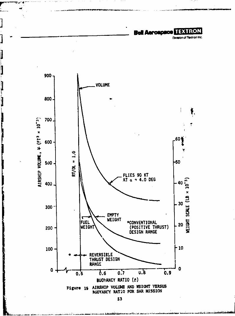
8-w @m fn 91TO-"
] *-l on of Textron Inc.
900
3 .VOLUME
800.
700
'i X 600
600
500 . ,50
FLIES 90 KTCe 4AT a 4.0 DEG64400- -40
300 30
EMPTY
FUEL WEIGHT *CONVENTIONAL
20WEIGHT (POSITIVE THRUST) 2DESIGN RANGE
100 - 10* REVERSIBLE
THRUST DESIGNRANGE0 ..-AV, - ' I I---- """
0. .5 UA0.9
BUO'VANCY RATIO ()
Figure 19 AIRSHIP VOLUME AND WEIGHT IERSUSBUOYANCY RATIO FOR SAR MISSION
53
DOmton of Textron Inc.
1.5 ] VOLUME
IJI*
FLIES 90 KTC. AT NEARLY
ZERO-DEGREE 125NGLE OF
FUEL WEIGHT AACK
0.5 100O
EMPTY -xWEIGHT cc
-J
,0---
IIIa75
t U. ,'. -
0.5 0.6 0.7 0.8 0.9
BUOYANCY RATIO (0)
Figure 20 AIRSHIP VOLUME AND WEIGHT VERSUSBUOYANCY RATIO FOR NO/MP MISSION
54
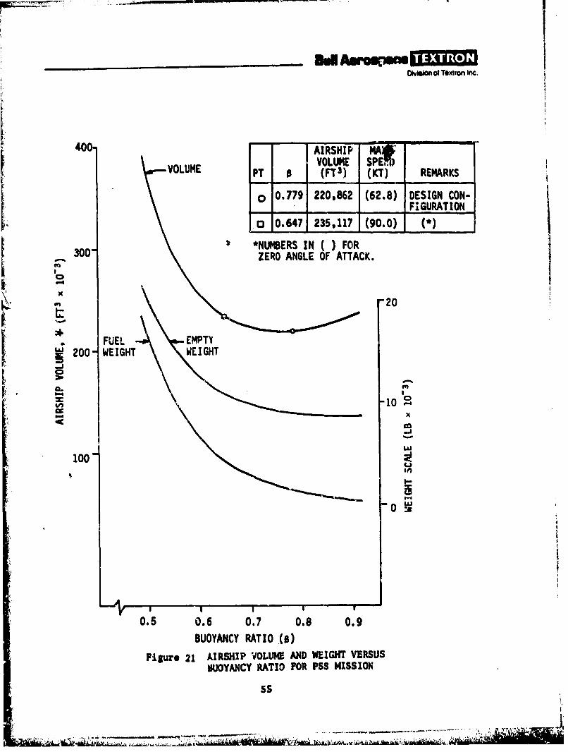
_ _ _ _ __ _ _ _ in AsrCW 1Division of Textron Inc.
40-AIRSHIP AVOLUME SP El,
VOLUME PT 0 (PT 3) (KT) REMARKS
o 0.779 2200862 (62.8) DESIGN CON-
_______________ ____________ FIGURATION
0.647 235,117 (90.0) (*
300 *NUMBERS~~ IN ()FORZERO ANGLE OF ATTACK.
20
FUEL EMPTYI200- WEIGHT WEIGHT
LJ
100
0.5 0.6 0.7 0.8 0.9
BUOYANCY RATIO (o)
Fi&Ure 21 AIRSHIP V0LLtt4 AND WEIGT VERSUSSULIYANCY RATIO FOR PSS MISSION
55
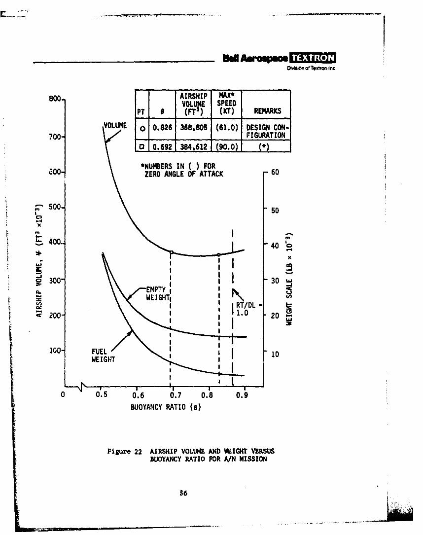
I', ,..-y
Division of Textron Inc.
800- AIRSHIP MAX*VOLUL4E SPEED
PT 0 (FT,) (KT) REMARKS
VOLUME 0 0.826 368,805 (61.0) DESIGN CON-
700- - - FIGURATION
13 0.692 384.612 (90.0) )
*NUMBERS IN ( ) FORGO0- ZERO ANGLE OF ATTACK 60
500-
x
400. 40
300-i 30 uEMPTY 0
v J RT/DL !:
200" .0 20
100 FUEL 10
I II!
0 0.5 0.6 0.7 0.8 0.9
BUOYANCY RATIO (0)
Figure 22 AIRSHIP VOLUME AND WEIGHT VERSUSBUOYANCY RATIO FOR A/N MISSION
56
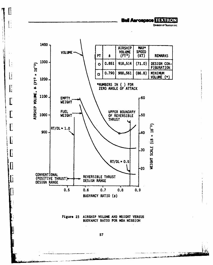
.L o i Textron Inc.
1400 -
AIRSHIP MAX*VOLUME VOLUME SPEED
PT (FT3) (KT) REMARKS
1300- 0 0.851 918,514 (71.0) DESIGN CON-o _FIGURATION
a 0.790 900,5 (86.8)MINIMUM12o _VOLUME (*)t
U 1200 *NUMBERS IN() FOR
V * ZERO ANGLE OF ATTACK
1100 EMPTY 60WEIGHT
FUEL UPPER BOUNDARYI 1000 WEIGHT OF REVERSIBLE 50THRUST
RT/DL- 1.0 *0
900- -40
-30 "j
RT/DL O.5
-20CONVENT ONAL REVERSIBLE THRUST(POSITIVE THRUST)-- ESIN R USTDESIGN RANGE DESIGN RANGE
0,5 0.6 0.7 0.8 0.9
BUOYANCY RATIO (0)
Figure 23 AIRSHIP VOLUME AND WEIGHT VERSUSBUOYANCY RATIO FOR MSA MISSION
S7
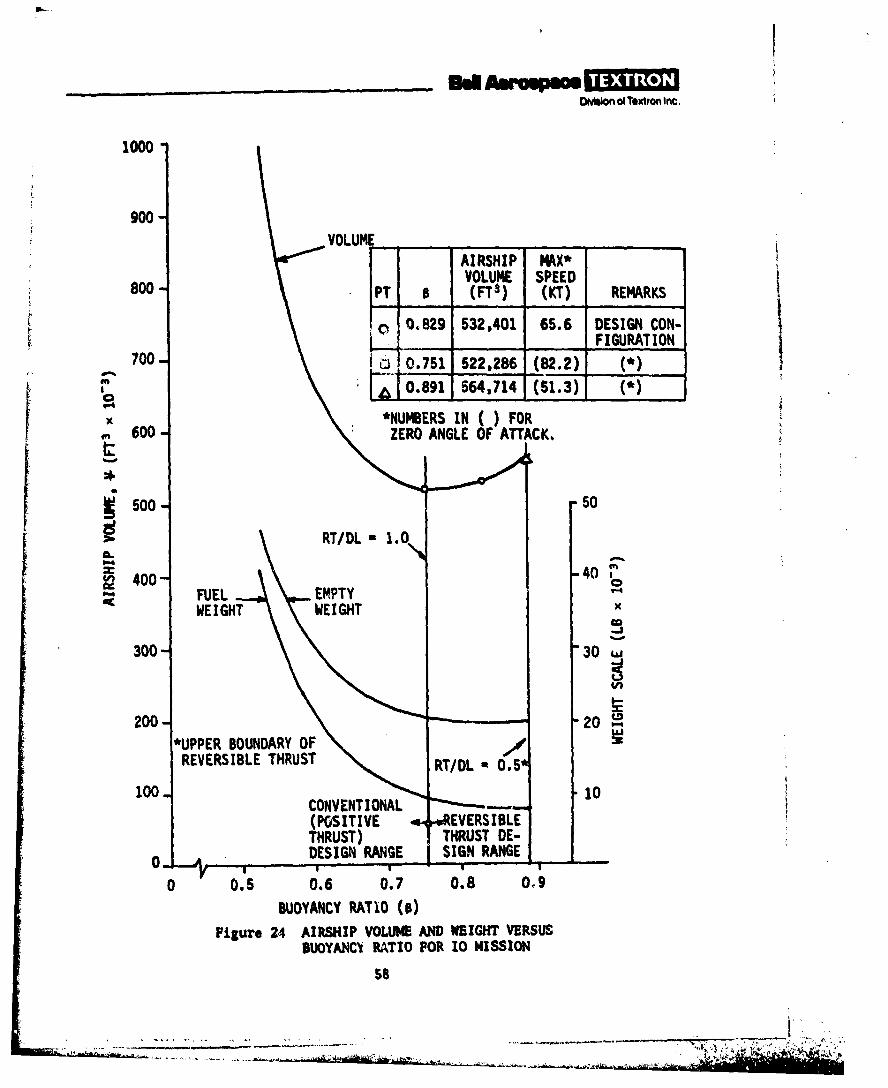
DyMion ofTextron Inc.
1000
VOLUME ___
AIRSHIP MAX*
800-P VOLUM4E SPEEDPT 0 (FTI) (KT) REMARKS
0, 0.829 532,401 65.6 DESIGN CON-700 FIGURATION700-075 522,286 (82.2) ()
X *NUMB5ERS IN ()FORrn600ZERO ANGLE OF ATTACK.
I00 50
00 WEIGHT WEIGHT 40
"UPPER BOUNDARY OFREVERSIBLE THRUST
100-1
Figur24 (AISIVOE -AEITVERS USL
SUOYANCI RATIO FOR 10 MISSION
58
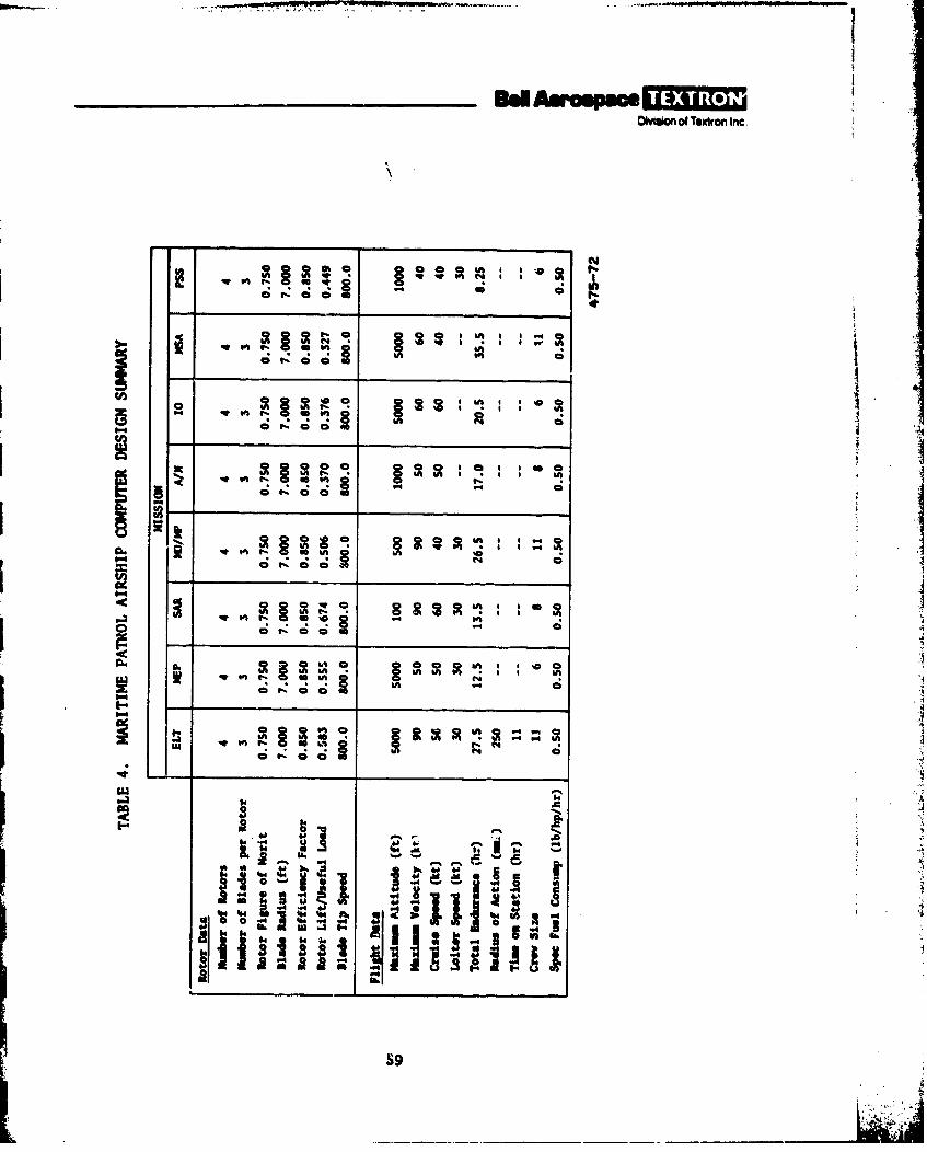
Olvaion of Textron Inc.
CY
I- C;
e.. C; C
OthC
C; C
in t 6A IA 4
InI%.. 40 N
1-
S9
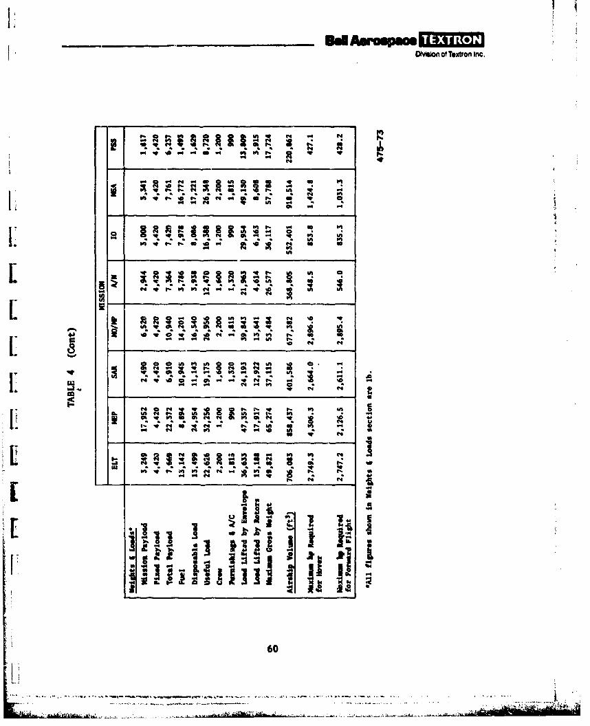
OMuio of Textton Inc.
?.@t~ @ @ @S % rLh
.4 in 6-4 4 A 4 %D4 .
@ @U-O @ e -1 -at O
en ~ ~ ~ i t sI O
Ll Lin10 A
of 9- on ILIA
.4.
.44
* ~ 1N
60A
L ~ a~aa aaagaa
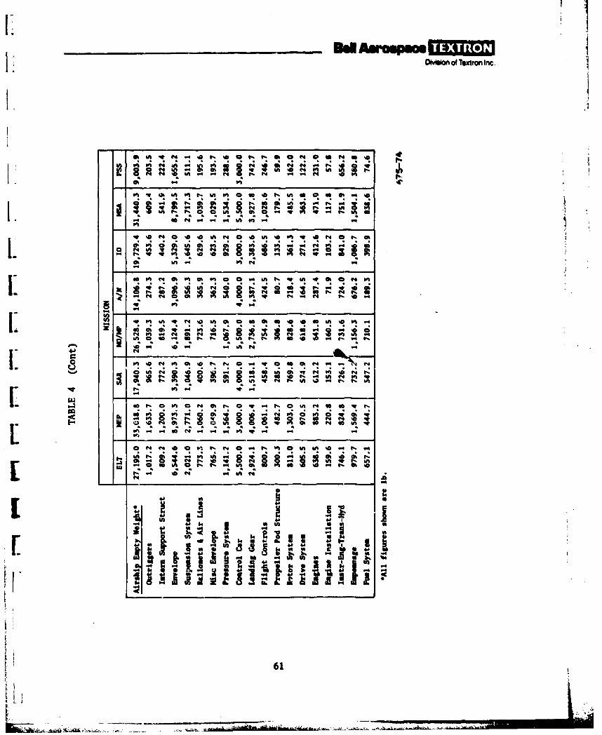
0~hiofoTextmn Ilnc
* ft A .41 o 01 % aO I " s m ft
V 14 A4P
, Nl -i ". Mh on .4 '
L0o*"lot 4 ~ N'
&n a a N- .4 N 4
t e4 'M
00 m '0. '4C; .
to, N VaO R 1% r% w . 4 t. go f4 M%D oh ? N 4 N
I.- c r. 34 .4 g .
.4 o[ii a.~~ - @41% 0 6 1 W S
W U N U61

SOwmbon of Textron, -fIeC
C4 so___"I__ ___
C4 so 00N
LL
ri c %a 0
NN N ci Go (4N mh ~
t- a v- Q aaa
00 Q n Lh 00 % 0 m00N
- "4 s N ~""
07 0
.~~ ~ in W. e 0 4 .d4
to -4 "4 P
in, Ln 9- "4L NOC; C; c;c c D0 01% 0000
in %D N so ch
0 b2
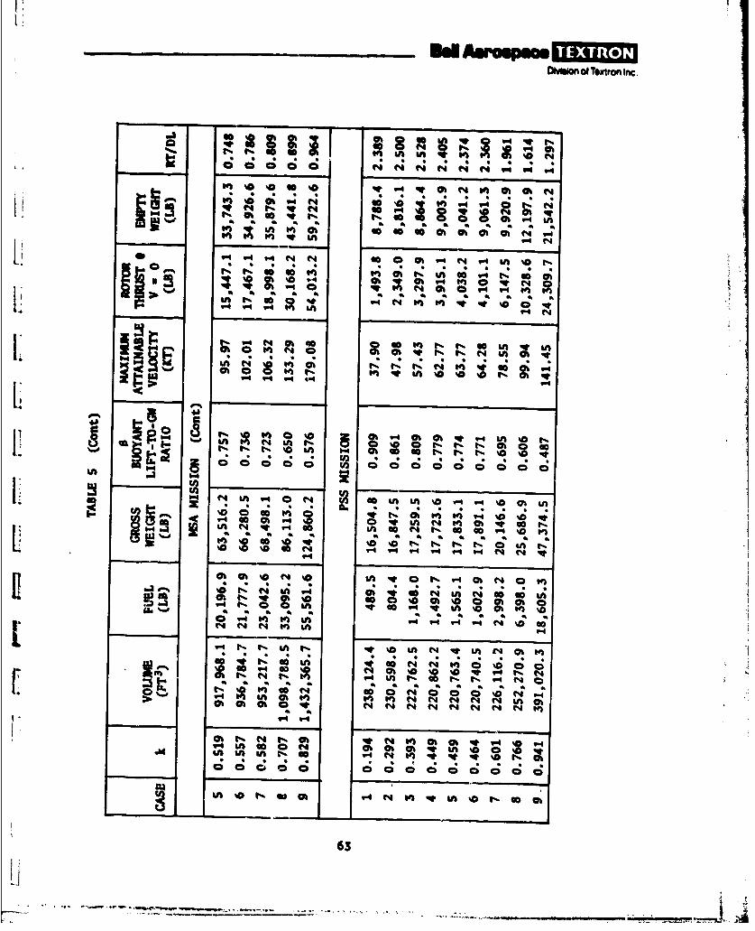
OM~bof @ Textron inc,
6 .
40 W" uv; t; 0; 4;0 Ok ll* 4
1t fa "ItNo n
- f t- 0 P%4 t-02 G%D 9' go_-_I.._-_N
C ; ; C 0 0 C C ; c ; C ; ; - 4C
LnI1 I L a g
oo M &A "I at V GotV ~ U "i o n o 0 0c c N
NotN
oG V4 V ,- - i . % mC[N N N w -0t.0C
- ~ % lbS 63

________ad aJmm -0- 1toDivhion of Textron Inc
ge% 14 V4
N~~C C;""4 4 ' - -.
* ~ ~ ~ C C. * * * * 4 "
Ch 4 cv hOh00 r 0 v0 mh w
v 4 4 - -LA4" N N G N %a
4-6
1-4 M. N ao m"4 "4 N
00 M I Go 00 ihO F-N '0 LA0.
"M N40 % IS 0 r4 V4V Ohj N~ 4eq %V V-O %0 00U " 000000-4 V-. ' ~ o i
IAIn
Ivs %a00 0h h i 0V "4 N th e4~ " ' "
at~~I at &A I s4
ini00 n 0 n n -40 00 NC) 4 V0004 r- C4 A
a*.0 % a an a4 a a a a a a a a4 a7 a aat V 4 go 0O W) Nh" No W' m-O Ch v @0V0t Ch
"A944 m "4 -q 4C
C04 in 11-00 Qh I NO %0 h@ N Oh 00Ln *aOtLtif " Ch &0%CA "41 M Nn '0L % Oh
44 0 tqn" 14 IA 0n @0 'D too "4h I [email protected] CA4 I1t f- N4 LAI Nl % Oh 3 "
OhN C; C; 0I C;C; C; N0 '0 ON; C; C;
U3 h0- 0 0 4' h~N N I O
thhhhhh4 A hIIILAAA~
64
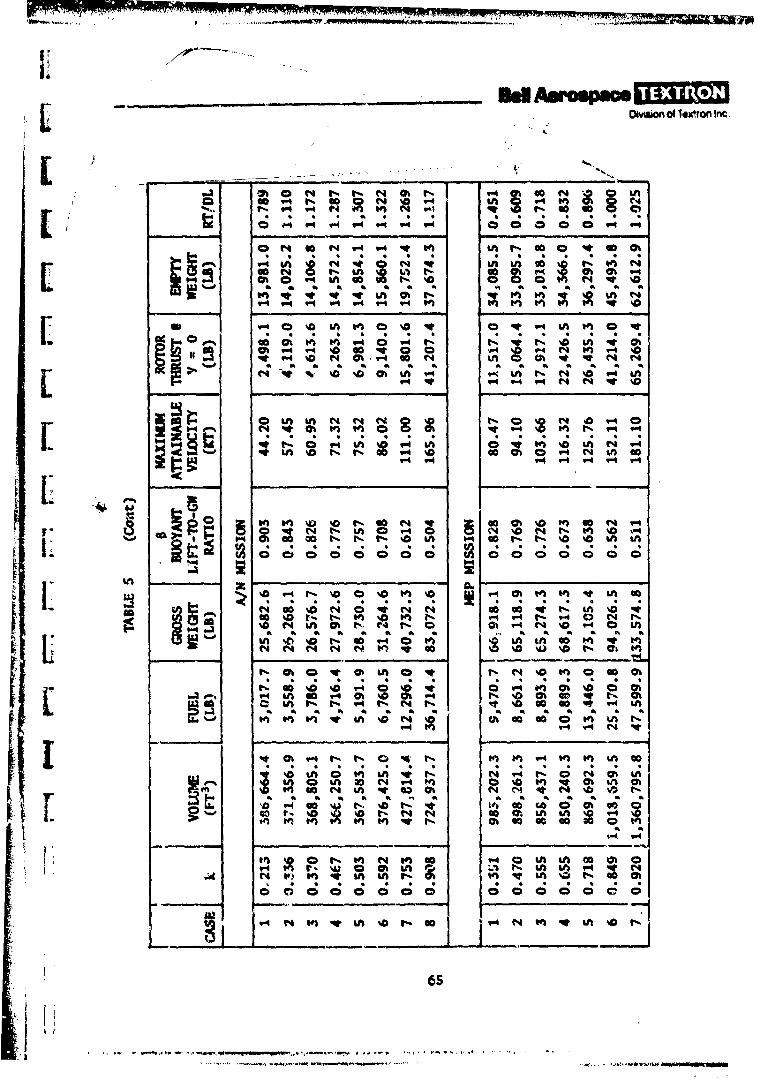
wmso d4 leron' Inc
~.4At~N ~ r .4
9- N C!~ O
0~ w~ t% 60( V%
CA 0 * 0; t4 14 ' 4 t
at ". "4 s a* V C) 0 on * qS
VP_% N al 40 N
[ kn N N '0% t
O W fl NN '0 n 0 C I 4 enr tV
-n %D f- INI cca-" inI cc
00Z V- %0 "%O t- ND -4~0E0% 0NG tl s rC-, %D in r-~0~ t% %D %a A
I.0.%aN OO Ot Cl~ N Nl 00l% 0f at
VON I h l (4 f. C§ -4 N D 90 - 0 IAAD A- A0 A; 1; LA m 0 1;
1W.
V4 1got ft4 0 0m 0
441 A ~ A 1A A A 1
t41-
0 0 m0 000 00 C 0 0 Q0 0
65
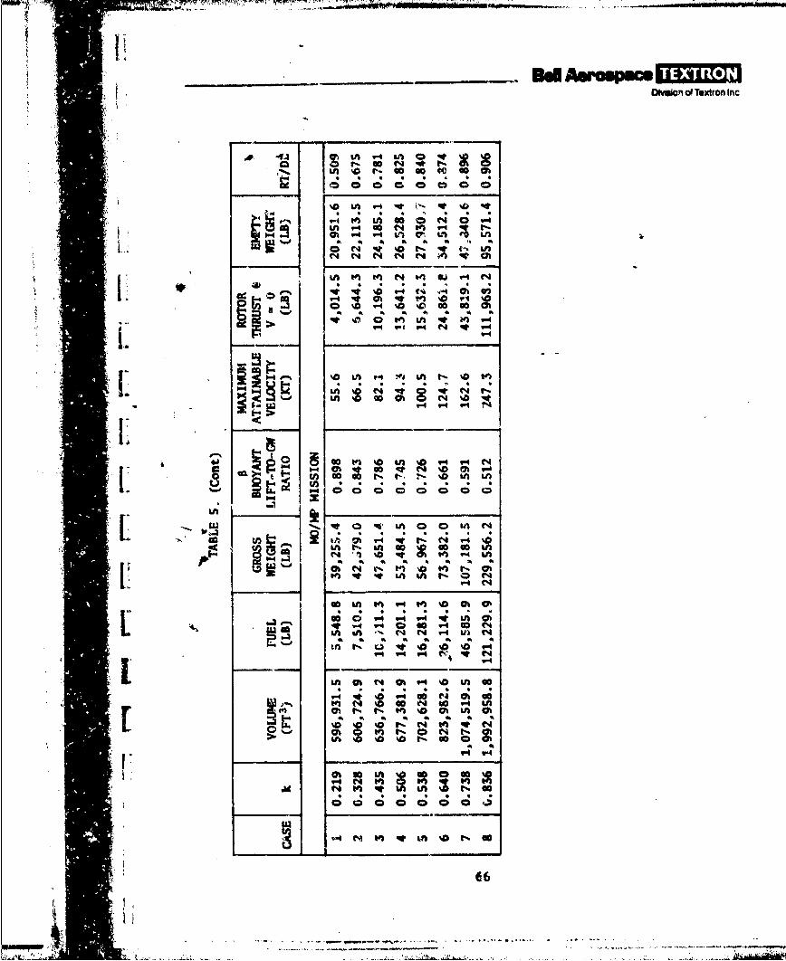
DOmdo' of Textron Inc
Ct t 4 t r%
'0 VU4 V4 4n o, LM '0
u-i ~Y v~ na O 0 .
Ut ~ ~ - N.w N St"
0 0 4 n '0 t%
'44 in "4 0 1 'Ch o N %0 com
gu CD~ CD 94 r4't~
a. fl.8 Utw 0 0 t
G! i " V- m 4 %D m
4m 0 4 4 14 LA, Cn
'.4A 0 t 0 0 0~
Ii~~7 Vt4ath 4
VL N In U
C; C; t 0 Oh stO
J A A A A A A
_ _ _ _ _ _ _ 9d Aerospae[Do v vCon of Textromn Inc.
4 S. MPA POINT DESIGN SELECTION
?he MPA point &esign selection must be made primarily on the basis of the missionrequirements and re~ated costs. Obviously. any airship size can be builtwithin the range of sizes i'-ing considered for the MPA missions. It is, ofcourse, impractical to recommend that a different airship be built for eachmission. !n fact, a single design which would perform all of the missionswould be most desirable. Hlowever, the size would necessarily be as large asthe largest airship of the group, and possibly larger. If costs are a drivingfactor for the first prototype airship, it may be practical to build a smallerairship that will accomplish the higher priority missions. The selection mustconsider the mission needs, other means to accomplish the mission, and thevalue of the mission.
However, although an effort is made here to select the best design for an
initial, multimission WA point design selection, the final selection must be madewith consideration of cost and mission parameters that are beyond the scope ofthe work in this program.
Figure 25 shows the computer airship size, or volume, as a function of buoyancyratio (S - buoyant lift/gross weight) for different MPA missions. It can beseen in the figure that there is a rather well defined optimum size for eachmission. It also shows that the minimum airship volume for all the variousmissions occurs between buoyancy ratios of 0.70 and 0.90.
Figure 17 shows the airship volume, empty weight, and the fuel weight as afunction of buoyancy ratio for the ELT mission, which has the highest priorityof the eight missions. The lower the buoyancy ratio, the greater the thrustrequired for the airship to hover. However, the greater the thrust capability,the greater the dash speed capability. Therefore, the dash speed and volumeboth increase as the buoyancy ratio decreases. The insert on the figureindicates the top speed capability for three specific designs on the curve.Figure 26plots the airship dash speed versus volume for the various MPAmissions.
For the ELT mission, the airship weight is not minimum *ith the minimum envelopevolu.ie. Figure 17 shows that the minimum vehicle weight occurs at a somewhathigher buoyancy ratio. Therefore, since cost is usually a direct function ofvehicle weight, the lowest airship weight would tend to determine the minimumvehicle cost. For the ELT mission, however, a 90-knot-dash-speed requireiaentestablishes the required propulsion system weight and thrust, which in turndetermine the minimum airship size for that propulsion system. The buoyancyratio for this design turned out to be 0.759 (figure 17).
Figure 17 also shows the rsnge of airship sizes and buoyancy ratios where revers-ible thrust is requireJ if ballast or ballast transfer is not desired (ie. thevertical lines of RT/DL * 1.0 and 0.S. At design values of RT/DL < 0.S, the
67
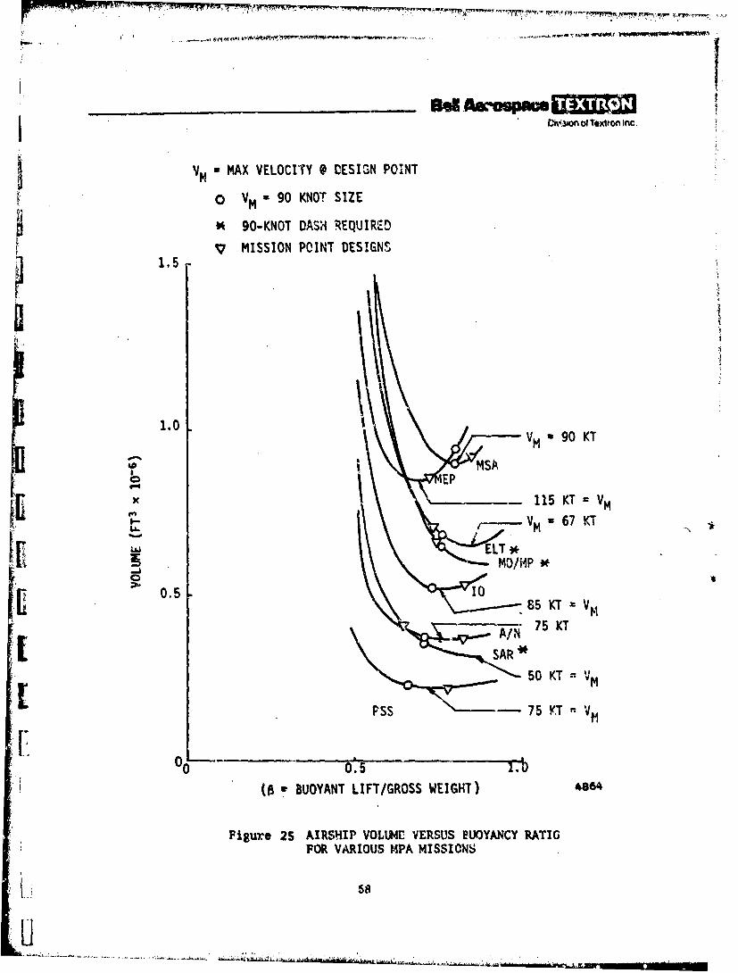
CiW.on of Textron Inc.
VM * MAX VELOCITY @ DESIGN POINT
0 VM - 90 KNOT SIZE
t, 90-KNOT DASH REQUIRED
v MISSION POINT DESIGNS1.5
1.0VM 90 KT
LU
MOP
0.5 - 05 KT - Vm
~~SAR..
_ 50 KT =V M
! (0 v BUOYANT LIFT/GROSS WEIGHT) 4.e6,4
Pigu e 25 AIRSHIP VOLLUI VERSUS BUOYANCY RATIOFOR VARIOUS MPA MISSIONS
i.8
U. 5

Division of 7%x'"ri Inc.
LAI~Cii
a ii
/.a.
6--
(C.01 x VIA) 3W1,J^ dI SSJUI
I 9
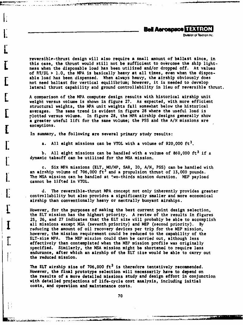
lb I. Division of Toxtron Inc.
reversible-thrust design will also require a small amount of ballast since, inthis case, the thrust would still not be sufficient to overcome the ship light-ness when the disposable load has been utilized and/or dropped off. At valuesof RT/DL > 1.0, the MPA is basically heavy at all times, even when the dispos-able load has been dispensed. When always heavy, the airship obviously does
L not need ballast for vertical equilibrium; however, it is needed to developlateral thrust capability and ground controllability in lieu of reversible thrust.
A comparison of the MPA computer design results with historical airship unitweight versus volume is shown in figure 27. As expected, with more efficientstructural weights, the MPA unit weights fall somewhat below the historicalaverages. The same trend is evident in figure 28 where the useful load isplotted versus volume. In figure 28, the MPA airship designs generally showa greater useful lift for the same volume; the PSS and the A/N missions areexceptions.
In summary, the following are several primary study results:
I: a. All eight missions can be VTOL with a volume of 920,000 ft3.
b. All eight missions can be handled with a volume of 860,000 ft3 if adynamic takeoff can be utilized for the MSA mission.
c. Six MPA missions (ELT, MO/MP, SAR, 10, A/N, PSS) can be handled withan airship volume of 706,000 ft3 and a propulsion thrust of 13,000 pounds.The MSA mission can be handled at two-thirds mission duration. MEP payloadcannot be lifted in VTOL.
d. The reversible-thrust MPA concept not only inherently provides greatercontrollability but also provides a significantly smaller and more economicalairship than conventionally heavy or neutrally buoyant airships.
However, for the purposes of making the best current point design selection,the ELT mission has the highest priority. A review of the results in figures25, 26, and 27 indicates that the ELT size will probably be able to accomplishall missions except MSA (seventh priority) and MEP (second priority). Byreducing the amount of oil recovery devices per trip for the MEP mission,however, the mission requirement could be reduced to the capability of theELT-size MPA. The MEP mission could then be carried out, although lesseffectively than contemplated when the MEP mission profile was originallyspecified. Similarly, the MSA mission might be shortened to require lessendurance, after which an airship of the ELT size would be able to carry outthe reduced mission.
The ELT airship size of 706,000 ft3 is thereiore tentatively recommended.However, the final prototype selection will necessarily have to depend onthe results of a more detailed missions study and design effort in conjunctionwith detailed projections of life-cycle cost analysis, including initialcosts, and operation and maintenance costs.
70
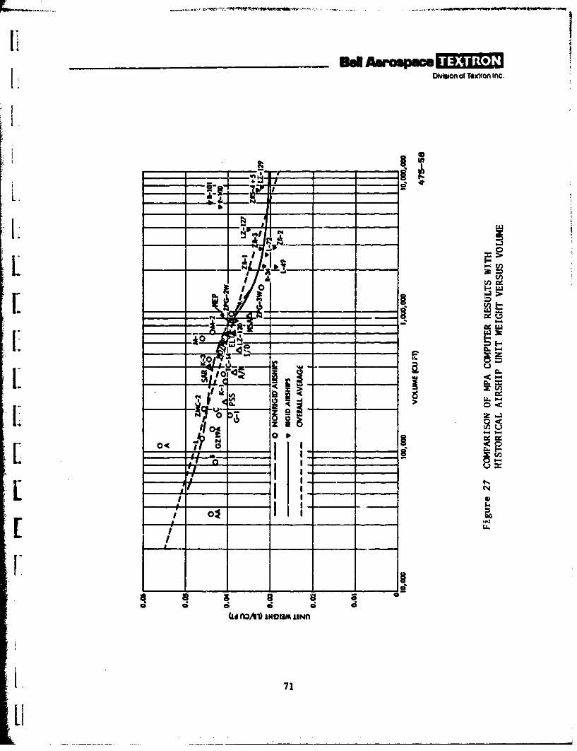
aIi1. Divson of Textron Inc.
I .mJ. I
_, I _
:111
k- +LL. _
I +.I
o0 <
roZ,
01 ix_
_ _ _ _-4 R- z _ ___ __
[ , __ ___ ___ LI
101
71
iLi
L Oivomon of Textron Inc
1L
1.-
RMGID ARHP YDROGEN INFLATED-
RIGID AIRSHIPS -------- V HELIUM INFLATED --I.NONRIGID AIRSHIPS- - 0 L- I
I: F-4
L-4 R'
kb NSA
1~E -120____
VOLUM AC l
Figure 28CMAIO FMACOPTRRSLSW
HISTORICAL C AIRSHI USFU IFTVRUSVLM
720

!I
_____ nAso P M 3e=DiionT of exron Inc.
6. CONCLUSIONS
The following conclusions and recommendations have evolved as a result of thisstudy:
a. MPA designs look entirely feasible and will be able to accomplish anyor all of the missions considered herein.
b. With the application of recent Bell innovations and modern technology,it appears possible to eliminate the primary traditional limitations of pre-viously existing airships, ie, hover and low-speed control, ballast transfer
S[ requirements, and ground handling.
c. No technological breakthroughs are necessary to develop an MPA design.
d. Modern computer math model simulation engineering makes it possibleto optimize the size and volume and propulsion system for the airship for either
-specific or multiple-mission requirements.
Ii e. The Bell reversible-thrust airship design provides the maximum con-trollability and minimum airship size and cost for a specific mission.
11. f. The simplified Bell airship sizing and performance (ASP) computerprogram provides a very flexible airship design evaluation capability.
g. Flexi):ility of the ASP computer program indicates that greater useshould be made and that further subsystem refinements and life-cycle costingshould be incorporated into the program.
h. Computer designs of smaller, more controllable, higher-speed airsnips,that indicate lower costs, should be fully investigated.
1±
1-
7.3
_ _ _ _ _ _ _ _ _ d 0o pece.DMvonofTextronInc
7. RECOM4ENDATIONS
L . The following are recommendations for the near-future, follow-on developmenteffort of the MPA:
a. The current, Bell ASP computer program should be used to establishthe basic parametric trends for MPA sizing and performance.
b. The weight relationship in the ASP computer program should be modi-
fied to improve the program flexibility. Although the program has already
modified the reference 3 weight relationships to eliminate some inconsistencies,I it is felt that the subsystem weights can be more simply related directly to
their basic functions rather than being tied to the magnitude of the usefulload. As an example, the envelope weights should be a function of the envelopevolume, the engine weights should be a function of the rated horsepower, and
ithe propulsion system support structure weight should be a function of Vropul-sion thrust. Originally, they were all equated to a function of W a AU6, whereA is a factor and B is an exponent of the useful load, U. The values of A and Bare different for different subsystems. However, the usefulness of this functionis limited because the subsystems vary in their relationship to the useful loadfor different airship missions or concepts.
c. The methods of establishing subsystem design weights should also beL evaluated further. Although the current methods are very useful in terms of
showing performance and sizing trends, improvements to reflect more accuratesubsystem weight relationships would improve the absolute values of thecomputer results. The program could also be made to reflect future designtrends by incorporating factors for expected subsystem weight improvementsas a function cf time. Present weight estimates, however, should representthe current state of the art to best reflect the weight, size, and performanceof airships that would be currently designed.
d. Life-cycle costing should be incorporated into the ASP program. Theprogram should include prototype or first-unit costs, as well as multiple-unit costs, based on standard learning curves. Operating and maintenancecosts should also be included to provide the operational portion of the life-cycle costs.
r ,e. The performance and fuel utilization of specific MPA designs shouldbe examined for a range of payloads and missions other than those for whichthe MPA wera designed. This study will establish the range of payloads andmissions for which any specific airship design can be effectively utilized.
74
- . ..-.

1"AOIlVISO of Textron Inc.
f. The effects of airship heaviness (ross-weight-to-buoyant-lft ratio,GW/IL) on structural weight should be investigated since the load factor variessubstantially as a function of heavinessS. The increase in structural weightdue to increases in bending moment resulting from increasing heaviness must beconsidered in the desigvi. It does not appear that references 3 and 6 haveadequately taken this into account, although those airships have been generallydesigned to be quite heavy.1
5Pa2'owt2'ia Stwb4 of Dtjno Lift Aerostate for' Future NavaZ Mieetona (Good-yea Aerospace Corporatinn, GER 13564, January 31, 1968) AD-833958.6Peahibi4ity of Modez"s Aiz'.hip--.Ph. I (Goodyear Aerospace Corporation,NASA CR-151917, September 1976) volume 1, book I.
75
O DWon of Textron Inc
I;t
REFERENCES
1. S. B. Spangler and C. A. Smith, TheoretioaZ StU4 of AZ-Rotor AerocjnamiIn rferenoe on 3mib,.ant VehioZ" (Nielsen Engineering and Research,Inc., NASA CR-152127, April 1978).
2. Albert Strumpf, A, Analyse of the Turning Charaote'istioe of the XZP Air-
ship Based upor. Undezmater, F',oed-9urning Nodel EZprimentes (StevensInstitute of Technology, Report SIT-DL-54-534, October 19S4).
3. DevelZM.ent of Wight Estimating Relction-hipe for Rigid and Non-RigidHeavB y Lift Airshipe (Goodyear Aerospace Corporation, NASA CR-151976,March 1977).
4. J. J. Vorachek, Invaetigation of Powered Lighter-Than-Air Vehiozes (AirForce Cambridge Laboratories Contract No. F1962867C0047, Scientific ReportNo. 1, Goodyear Aerospace Corporation CER 13140, February 28, 1967).
S. lfacivnetrio Study of Thjnmiio Lift Aeroatate for Futuire NavalZ Missions (Good-year Aerospace Corporation, GER 13564, January 31, 1968) AD-833958.
- 6. Yeasbitity of Modern Airshipe--PP, II Z (Goodyear Aerospace Corporation,
NASA CR-1S1917, September 1976) volume I, book I.
I76
[
IiI.
!7
L.

.... * " w - -, ., ..... ...- -- * -,. ,--.-w ---"
--
.. ..
DIvision of Textron Inc
I
II
APPENDIX A
BELL AEROSPACE TEXTRONRENDEZVOUS 40 ,
NI1#l
U_ _ ________

(-
ii~4 ~
* . :; £ - g S.
OrgWW wo IW-- - --- --
Li
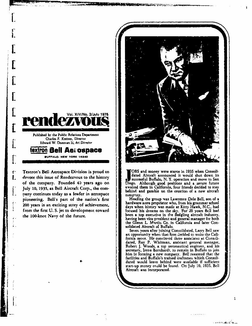
I.. Vol. XIV/No. 2/July 1975
rendezwu_Published by the Public Relations Department
Charles F. Kreiaer. DirectorEdward W. Donovan 11, Art Director
textron Bell Aewospace" SUFFAL.. NEW VORK 1,44o
4.. I
T- Textron's Bell Aerospace Division is proud to lOBS and money were scarce in 1935 when Consoli-d dated Aircraft announced it would shut down its
.- devote this issue of Rendezvous to the history .Jsuccessful Buffalo, N. Y. operation and move to Sanof the company. Founded 40 years ago on Diego. Although good positions and a secure futureJuly 10, 1935, as Bell Aircraft Corp., the com- awaied them in California, four friends decided to stay
behind and gamble on the creation of a new aircrapany continues today as a leader in aerospace compkny.pioneering. Bell's part of the nation's first Heading the group was Lawrence Dale Bell, son of a
hardware store proprietor who, from his grammar school200 years is an exciting story of achievement, days when history was made at Kitty Hawk, N.C., had
* from the first U. S. jet to development toward focused his dreams on the sky. For 20 years B1EI hadthe 100-knot Navy of the future. been a top exec,,tive in the fledgling aircraft industry,
having been vice president and general manager for boththe Glenn L. Mqrtia Co. in California and later Con-solidated Aircraft of Buffalo.
Seven years after joining Consolidated, Larry Bell sawan opportunity wher that firm ecided to make the Cali-fornia move. He convinced three assoclates at Consoli-dated, Ray P. Whitman, assistant general manager,Robert J. Woods, a top aeronautical engineer, and hissecretary, Irene Bernhardt, to remain in Buffalo to joinhim in forming a new company. Bell reasoned that thefacilities and Buffalo's trained craftsmen which Consoli-dated would leave behind were available if sufficientstart-up money could be found. On July 10, 1935, BellAircraft was incorporated.

Bell, as president, and Whitman, as first vice president In May 1936, before it celebrated its first birthday.and treasurer, walked from door to door seeking inves- Bell Aircraft received an Army contract for $403,057 totors. While they were pounding the pavements in search build an experimental model of the Airacuda. Mean-of money, Bob Woods, the new firm s chief design engi- time, earlier in the year, Bell was awarded a whoppingnear, was back in the tiny, second floor offlc~s In the old $800,000 contract from the Navy to fabricate wing pan-Consolidated plant working on plans. Immediately upon els and other parts for the Catalina flying boats of Con-incorporation, Larry Bell had sold $50,000 worth of solidated Aircraft.stock to close friends. But the firm hid incorporated for Eventually, the Army ordered 14 Airacudas, yet, in$500,000 and Bell knew he had to sell at least another spite of this, the contract proved a losing proposition for$300,000 worth of stock to be *n business. The deadline Bell, The 14 were the only Airacudas ever built. Whenfor the sale of stock was September. The entire month of put into the air, the new design indicated it was just tooJuly was spent In futile attempts to raise even another advanced in every way. In addition, the two Allisonnickel. Around the first of August, BeHl obtained another pusher engines were far underpowered for the craft itself.$10,000 from a local retail store owner. That broke the While the Airacuda was being assembled for deliverylogjam and other stock orders followed, to the Army, Woods was desigt.!-ig a brand new fighter
With the money In the bank, Bell Aircraft took over which was destined for immortality-the P-39 Airacobrathe 40,000 square feet of space formerly occupied by -a single engine craft capable of unheard of speeds ap-Consolidated on Elmwood Avenue and installed $35,000 proaching 400 miles an hour.worth of equipment. It was late September and Bell The revolutionar P-39 was a boon to Bell AircraftAircraft now had working capital. All it needed was a Corporation. In 1939 the Army, after obsei\'ing thecontract and a customer. They weren't long In coming. flight tests at Wright Field, officially accepted the air-The Army asked Bell to install an Allison V-1710 engine plane.in an A-lI attack plane being built by Consolidated Air- At the time the Army contr&t was received byBellcraft. The price on the contract was only $25,000, yet World War I exploded in Europe. Vice President Harryit too broke another logjam and was the start of Bell L. Collins came back to Buffalo with a $9 million orderAircraft's r!se in the aviation industry. Fifty men were for 200 A!racobras from the French, two million of it inhired to start the contract. cash. For the first time since lis formation, Bell Aircraft
Larry Bell and Ray Whitman continued their relent- had elbow room in its treasury. But as this order wasless pursuit of new orders while Bob Woods continued coming to fruition, France fell before the Nazi onslaught.to accumulate plans for a revolutionary airplane design. Larry Bell relied on his selling emissary once again audWoods' design was the YFM-1 Airacuda, a long range prevailed upon the British to take over the French con-fighter 1with two pusher propellers and radical remote tract.control armament consisting of a 37-millimeter cannon In October 1940 two significant milestones weremounted in each engine nacelle. In addition to the passed in the rapid growth of Bell A.ircraft. With a hostarmament, Woods later incorporated an innovation of dignitaries on hand, ground was broken for thewhich years later was the accepted design in all aircraft $1,050,000 plant !n Wheatfield, N. Y. Two days later, on-the tricycle landing gear for easier handling on take- Columbus Day, the first production model of the P-39offs and landings. Airacobra was delivered to the Army Air Corps at
Wright Field.On January 19, 1940, the Bell Airacobra had per-
formed successfully at an Army Air Corps demonstrationat Bolling Field in Washington, D. C. It was the firstP-39 to roll off the Bell assembly line as a result of theArmy order the previous year. A few weeks later thatsame plane, with Captain George E. Price at the con-trols, was going through its paces above the Buffalo Air-port for the benefit of visiting Army brass.
The cold February winds and the high altitudes hadfrozen the plane's landing gear. Larry Bell, himself, onathe ground, ordered Captain Price to bail out. The pilot .,]ignored the instructions. To allow the plane to crash
YFAI-1 Ai, red, would set Bell Aircraft and the Army Air Corps backmary, many months. Price made a belly landing andescaped unhurt.
The Airacobra was leading Bell Aircraft to spectacularheights. More than 10,000 Alracobras were eventuallyproduced by Bell. But obsolescence was the Airacobra's
2
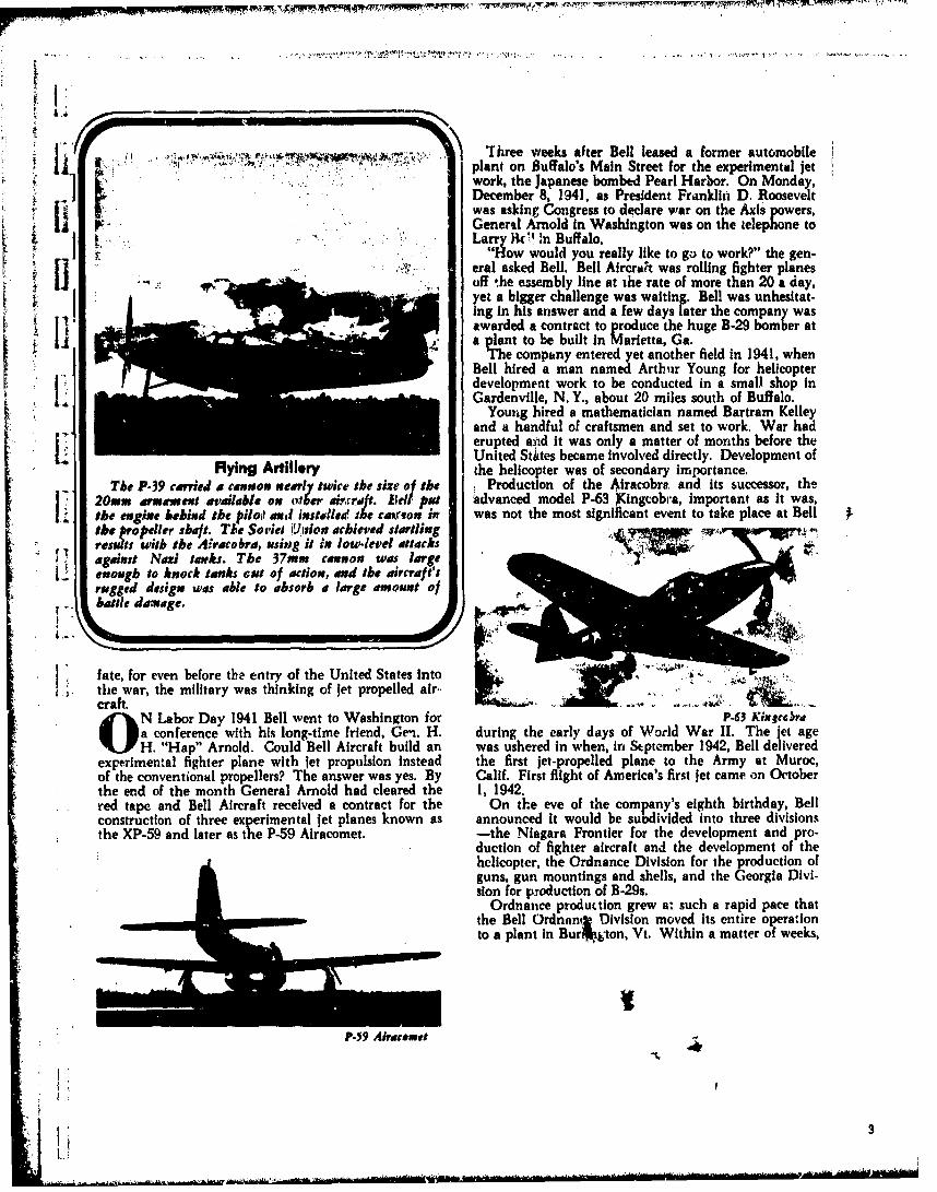
U a , ': T"rhree weeks after Bell leased a former automobile~ 11 ~ ~plant on Buffalo's Main Street for the experimental jet
1r ! "work, the Japanese bombed Pearl Harbor. On Monday,I December 8, 1941, as President Franklin D. Roosevelt
was asking Congress to declare war on the Axis powers,General Arnold in Washington was on the telephone to[; :. ,- " : ., :.i :' ' '.. La,,r Ac In Buffalo.
, " ,"$,ow would you really like to go to work?" the gen-eral asked Bell. Bell Aircrat was rolling fighter planes
S ff the assembly line at the rate of more than 20 a day,yet a bigger challenge was waiting. Bell was unhesitat-ing In his answer and a few days later the company was
13 awarded a contract to produce the huge B-29 bomber ata plant to be built in Marietta, Ga.
The company entered yet another field In 1941, whenBell hired a man named Arthur Young for helicopterdevelopment work to be conducted in a small shop inGardenville, N. Y., about 20 miles south of Buffalo.
Young hired a mathematician named Bartram Kelleyand a handful of craftsmen and set to work. War had
[I erupted and It was only a matter of months before theUnited Stites became involved directly. Development of
Flying Artillery the helicopter was of secondary importance.The P-39 carried a cannon nearly twice the size of the Production of the Airacobre, and its successor, ther2On rmemt avalable on alber a rcraft. lellput Advanced model P-63 Kingcobra, important as It was,the engine behind the pliss and, instdled Ike cmronlin was not the most significant event to take place at Bell
tbe propeller shaft. Tke Sovies i~irion achieved startling A lresults with the Airaco bra, using it in low-level attacksL . against Nazi tar ks. The 37mm cannon was largeenough to knock tanfks GIV of action, anod tbe aircraft'srugged design was able to absorb a large amount of
hattle damage.
fate, for even before the entry of the United States Intothe war, the military was thinking of let propelled air.,craft.
N Labor Day 1941 Bell went to Washington for P.63 Kitgccrraa conference with his long-time friend, Gen. H. during the early days of World War II. The jet ageH. "Hap" Arnold. Could Bell Aircraft build an was ushered in when, in September 1942, Bell delivered
experimental fighter plane with jet propulsion instead the first jet-propelled plane to the Army at Muroc,of the conventional propellers? The answer was yes. By Calif. First flight of America's first jet came on Octoberthe end of the month General Arnold had cleared the 1, 1942.red tape and Bell Aircraft received a contract for the On the eve of the company's eighth birthday, Bellconstruction of three experimental jet planes known as announced it would be subdivided into three divisionsthe XP-59 and later as the P-59 Airacomet. -the Niagara Frontier for the development and pro-
duction of fighter aircraft and the development of thehelicopter, the Ordnance Division for the production ofguns, gun mountings and shells, and the Georgia Divi-sion for production of B-29s.
Ordnance production grew a: such a rapid pace thatthe Bell Ordnanj Division moved its entire operationto a plant in BurM~gton, Vt. Within a matter of weeks,
P-.9 Airacomet
I'3

the Burlington plant' was tunring out a huge Armyorder for M-7 gum mount adapters. 4
The Niagara Frontier Division was turning out fighterplanes in record numbers, and in Georgia the first of663 B-29 Superfortresses was being readied for action..But in the little garage in Gardenville, prhaps an evenmore significant scene was being enacted. Arthur Youngand Bart Kelley had completed their first flying modelof a helicopter. Floyd Carlson, the test pilot, had takenthis experimental craft on several test runs.
Back at his drawing boards, Bob Woods was workingon the XP-77, an all plywood fighter plane. The worldwas aflame with war, and fear of an ultimate shortage Aof aluminum for the construction of flying craft, pro-duced the idea of building a plane made entirely ofwood. The all wood XP-77 was built and successfullytest flown.
In 1944 and until V-J Day in 1945 the Bell AircraftCorporation hit its peak production. In mid-1944 thelast Airacobra came off the production line at Wheat-field and the Superforts were being built at the rate oftwo a day in Marietta. Employment hit a new high of50,000. First Movable Tail
But the war's end brought with it a drastic cutback. In late 1974, Charles E. Yeager, then an Air ForceIn the matter of a few months employment was cut back brigadier general, recalled that the early X-1 experimentsfrom 50,000 to less than 3,000. The impact was tre- showed the need for the movdble tail that is standard onmendous. today's high speed aircraft. A few years later, the mov.
The B-29 plan, in Marietta was closed down, leaving able tail section was designed into the F86 jet "uhichBell with its plant at Wheatfield, in which it consoli- dominated the Russian MIG 15 in the Korean War,"dated all its Buffalo operatpns, and the one in Burling- General Yeager told members of the Lawrence D. Bellton. Eighteen months la#, the Burlington Division Chapter, Air Force Association, in Buffalo.was closed.
In order to keep the corporation from complete col- \lapse, Larry Bell played the ace he had been keeping in /the hole. He went out to sell the helicopter. In a fewweeis he had orders for three models. The Army AirForce wanted the five-place, 600-horsepower Model 48; cepts of the P-59 and the newer P-83 jet-powered craft,the Army and the Navy both asked for delivery of the Woods realized that contemporary jet engines wouldModel 47A, a two-place craft; and there were civilian not provide the thrust needed at high altitudes. If the-orders for the 47B, a commercial model in the 47 series. X-1 was to fly at altitudes where the atmosphere was
Early in March 1946, the Model 47 series was granted thin, it needed a new and extraordinary propulsion sys-the first commercial certification by the Civil Aeronau- tem. Thus, Woods designed the X-I around a rocket itics Administration. Two months later the same craft engine.was granted the first manufacturing type certificate. On October 14, 1947, the Bell X-l, with Air Force
The helicopter came of age in 1951 with the outbreak Capt. Charles Yeager at the controls, was dropped fromof the Korean War. More than two-thirds of all the the belly of a B-29 "mother ship" and sped off to ahelicopters flown in Korea were made by Bell. An esti- record speed faster than sound. No man before hadmated 20,000 wounded United Nations troops were travelled faster than 750 miles an hour. What Captainevacuated to safety by Bell helicopters and another Yeager's speed was on that maiden voyage, the military1,000 fighting men vwere rescued by helicopter, never revealed. But less than a year later Yeager was
In May of 1951 ground was broken for a helicopter clocked at the unheard of speed of 967 miles an hour.prodtction facility outside of Fort Worth, Texas. A few The sound barrier had been broken and the assault onmonths earlier, Harvey Gaylord had been named vice speed records continued at a fantastic rate.president for helicopter operations. The world's first supersonic flight In 1947 gained for
While Bell helicopters were gaining recognition Larry Bell, Captain Yeager and Bell Aircraft the covetedthroughout the world, the company's design engineers Collier Trophy.were busily sketching an experimental, rocket-powered Not only did the Bell X-1 and modified X-lA attackplane to be known as the X-1. Taking the basic con- speed records, they also were used to attain altitude rec-
ords. In the years after the first supersonic flight, therewere continuing competitions for one new record afteranother. The X-I hit an altitude record of more than70,000 feet and, late in 1953, the X-IA, again withChuck Yeager, by then an Air Force major, at the con-trols, /lashed through the sky over Edwards Air ForceBase in California at 1,650 miles an hour - two and a .
L 4
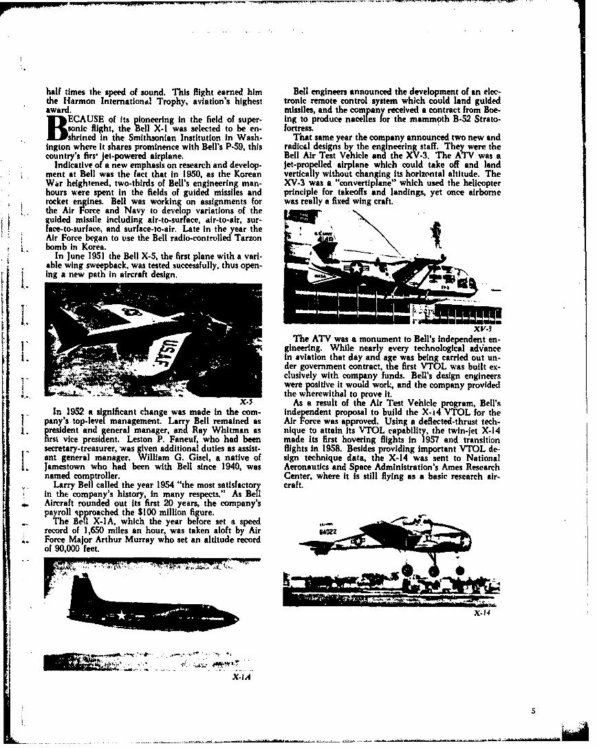
half times the speed of sound. This flight earned him Bell engineers announced the development of an elec-the Harmon International Trophy, aviation's highest tronic remote control system which could land guidedaward. missiles, and the company received a contract from Boe-B ECAUSE of its pioneering in the field of super- ing to produce nacelles for the mammoth B-52 Strato-'sonic flight, the Bell X-I was selected to be en- fortress.
shrined In the Smithsonian Institution in Wash- That same year the company announced two new andington where it shares prominence with Bell's P-59, this radical designs by the engineering staff. They were thecountry's firs' jet-powered airplane. Bell Air Test Vehicle and the XV-3. The ATV was a
Indicative of a new emphasis on research and develop- Jet-propelled airplane which could take off and landment at Bell was the fact that in 1950, as the Korean vertically without changing its horizontal altitude. TheWar heightened, two-thirds of Bell's engineering man- XV-3 was a "convertiplane" which used the helicopterhours were spent in the fields of guided missiles and principle for takeoffs and landings, yet once airbornerocket engines. Bell was working on assignments for was really a fixed wing craft.the Air Force and Navy to develop variations of theguided missile Including air-to-surface, air-to-air, sur-lace-to-surface, and surface-to-air. Late in the year theAir Force began to use the Bell radio-controlled Tarzonbomb in Korea.
In June 1951 the Bell X-5, the first plane with a vari- " &able wing sweepback, was tested successfully, thus open- w-ing a new path in aircraft design.
1v.
The ATV was a monument to Bell's independent en-gineering. While nearly every technological advancein aviation that day and age was being carried out un-der government contract, the first VTOL was built ex-clusively with company funds, Bell's design engineerswere positive it would work, and the company providedthe wherewithal to prove it.
X.5 As a result of the Air Test Vehicle program, Bell'sIn 1952, a significant change was made in the con- independent proposal to build the X-14 VTOL for the
pany's top-level management. Larry Bell remained as Air Force was approved. Using a deflected-thrust tech-president and general manager, and Ray Whitman as nique to attain its VTOL capability, the twin-jet X-14first vice president. Leston P. Faneuf, who had been made Its first hovering flights in 1957 and transitionsecretary-treasurer, was given additional duties as assist- flights in 1958. Besides providing important VTOL de-ant general manager. William G. Gisel, a native of sign technique data, the X-14 was sent to NationalJamestown who had been with Bell since 1940, was Aeronautics and Space Administration's Ames Researchnamed comptroller. Center, where it is still flying as a basic research air-
Larry Bell called the year 1954 "the most satisfactory craft.in the company's history, in many respects." As BellAircraft rounded out its first 20 years, the company'spayroll kpproached the $100 million figure.
The Bell X-IA, which the year before set a speedrecord of 1,650 miles an hour, was taken aloft by AirForce Major Arthur Murray who set an altitude recordof 90,000 feet.
X- 14
X.IA
5I' r . -- -
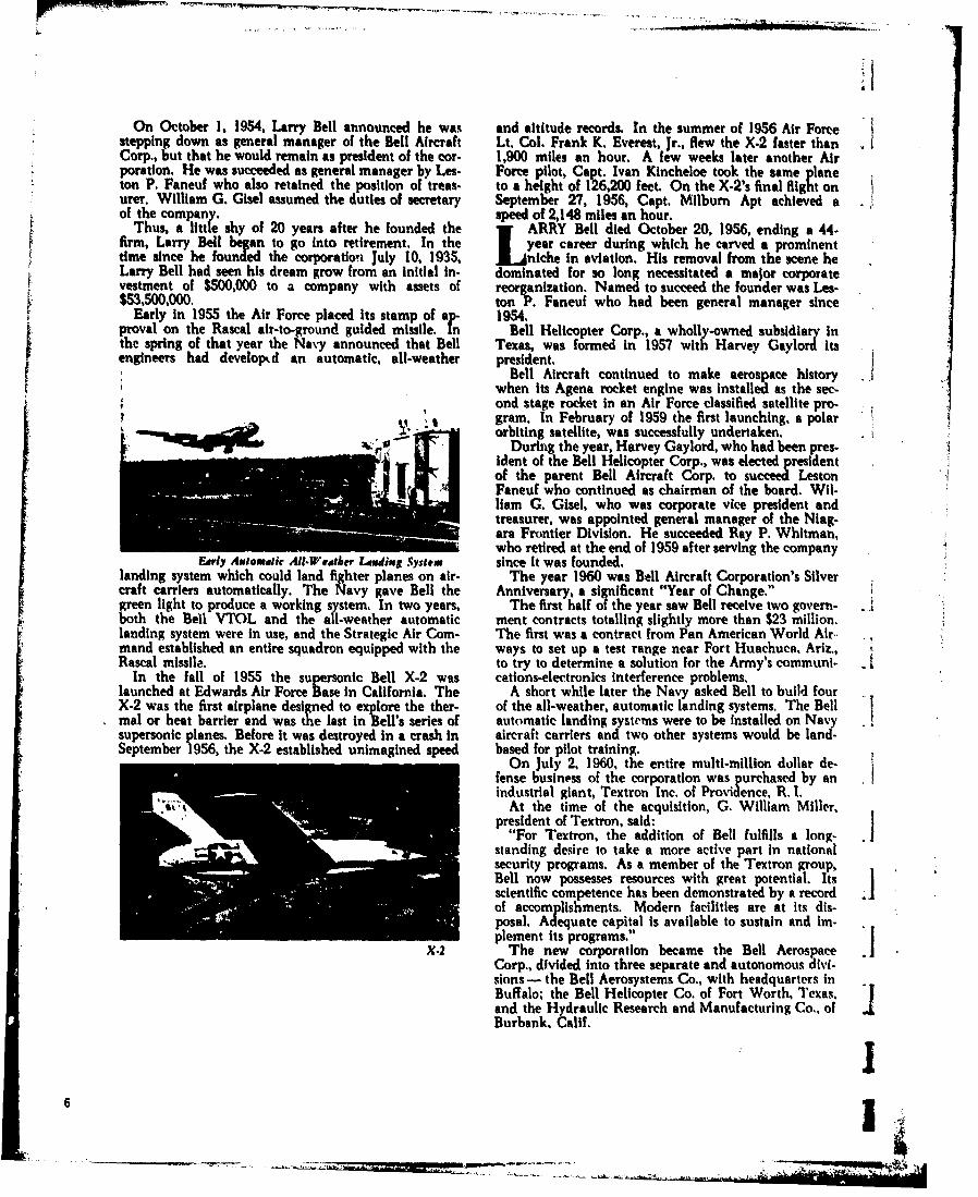
ii
On October 1, 1954, Larry Bell announced he was and altitude records. In the summer of 1956 Air Forcestepping down as general manager of the Bell Aircraft Lt. Col. Frank K. Everest, Jr., flew the X.2 faster thanCorp., but that he would remain as president of the cor- 1,900 miles an hour. A few weeks later another Air
* poration, He was succeeded as general manager by Les- Force pilot, Capt. Ivan Kincheloe took the same planeton P. Faneuf who also retained the position of treas- to a height of 126,200 feet. On the X-2's final Right onurer. William G. Gisel assumed the duties of secretary September 27, 1956, Capt. Milburn Apt achieved aof the company. speed of 2,148 miles an hour.
Thus, a little shy of 20 years after he founded the ARRY Bell died October 20, 1956, ending a 44-firm, Larry Bell began to go into retirement. In the 1 year career during which he carved a prominenttime since he founded the corporation July 10, 1935, jLniche In aviation. His removal from the scene heLarry Bell had seen his dream grow from an Initial in- dominated for so long necessitated a major corporatevestment of 50,000 to a company with assets of reorganization. Named to succeed the founder was Les-$53,500,000. ton P. Faneuf who had been general manager since
Early in 1955 the Air Force placed its stamp of a 1954.prval on the Rascal air-to-ground guided missile. n Bell Helicopter Corp., a wholly-owned subsidiary inh spring of that year the Navy announced that Bell Texas, was formed in 1957 with Harvey Gaylord its
engineers had developed an automatic, all-weather president.Bell Aircraft continued to make aerospace history
when its Agena rocket engine was installed as the sec-I ond stage rocket in an Air Force classified satellite pro- .
gram. In February of 1959 the first launching, a polarorbiting satellite, was successfully undertaken.During the year, Harvey Gaylord, who had been pres-
ident of the Bell Helicopter Corp., was elected presidentof the parent Bell Aircraft Corp. to succeed LestonFaneuf who continued as chairman of the board. Wil-liam G. Gisel, who was corporate vice president andtreasurer, was appointed general manager of the Niag-ara Frontier Division. He succeeded Ray P. Whitman,who retired at the end of 1959 after serving the company
Early Axiomatic All-Weater Landing1 System since it was founded.landing system which could land fighter planes on air- The year 1960 was Bell Aircraft Corporation's Silvercraft carriers automatically. The Navy gave Bell the Anniversary, a significant "Year of Change."green light to produce a working system. In two years, The first half of the year saw Bell receive two govern-both the Bell VTOL and the all-weather automatic ment contracts totalling slightly more than $23 million.landing system were in use, and the Strategic Air Coin- The first was a contract from Pan American World Air.mand established an entire squadron equipped with the ways to set up a test range near Fort Huachuca, Ariz.,Rascal missile. to try to determine a solution for the Army's communi- - I
In the fall of 1955 the supersonic Bell X-2 was cations-electronics interference problems.launched at Edwards Air Force Base in California. The A short while later the Navy asked Bell to build fourX-2 was the first airplane designed to explore the ther- of the all-weather, automatic landing systems. The Bellmal or heat barrier and was the last in Bell's series of automatic landing systems were to be installed on Navy .supersonic planes. Before it was destroyed in a crash in aircraft carriers and two other systems would be land-September 1956, the X-2 established unimagined speed based for pilot training.
On July 2, 1960, the entire multi-million dollar de-fense business of the corporation was purchased by anindustrial giant, Textron Inc. of Providence, R. 1.
At the time of the acquisition, G. William Miller,president of Textron, said:
"For Textron, the addition of Bell fulfills a long-standing desire to take a more active part in nationalsecurity programs. As a member of the Textron group,Bell now possesses resources with great potential. Itsscientific competence has been demonstrated by a record jof accomplishments. Modern facilities are at its dis-posal. Adequate capital is available to sustain and im-plement its programs."
X-2 The new corporation became the Bell AerospaceCorp., divided into three separate and autonomous divi-sions - the Bell Aerosystems Co., with headquarters inBuffalo- the Bell Helicopter Co. of Fort Worth, Texas,and the Hydraulic Research and Manufacturing Co., of 4Burbank, Calif.
6
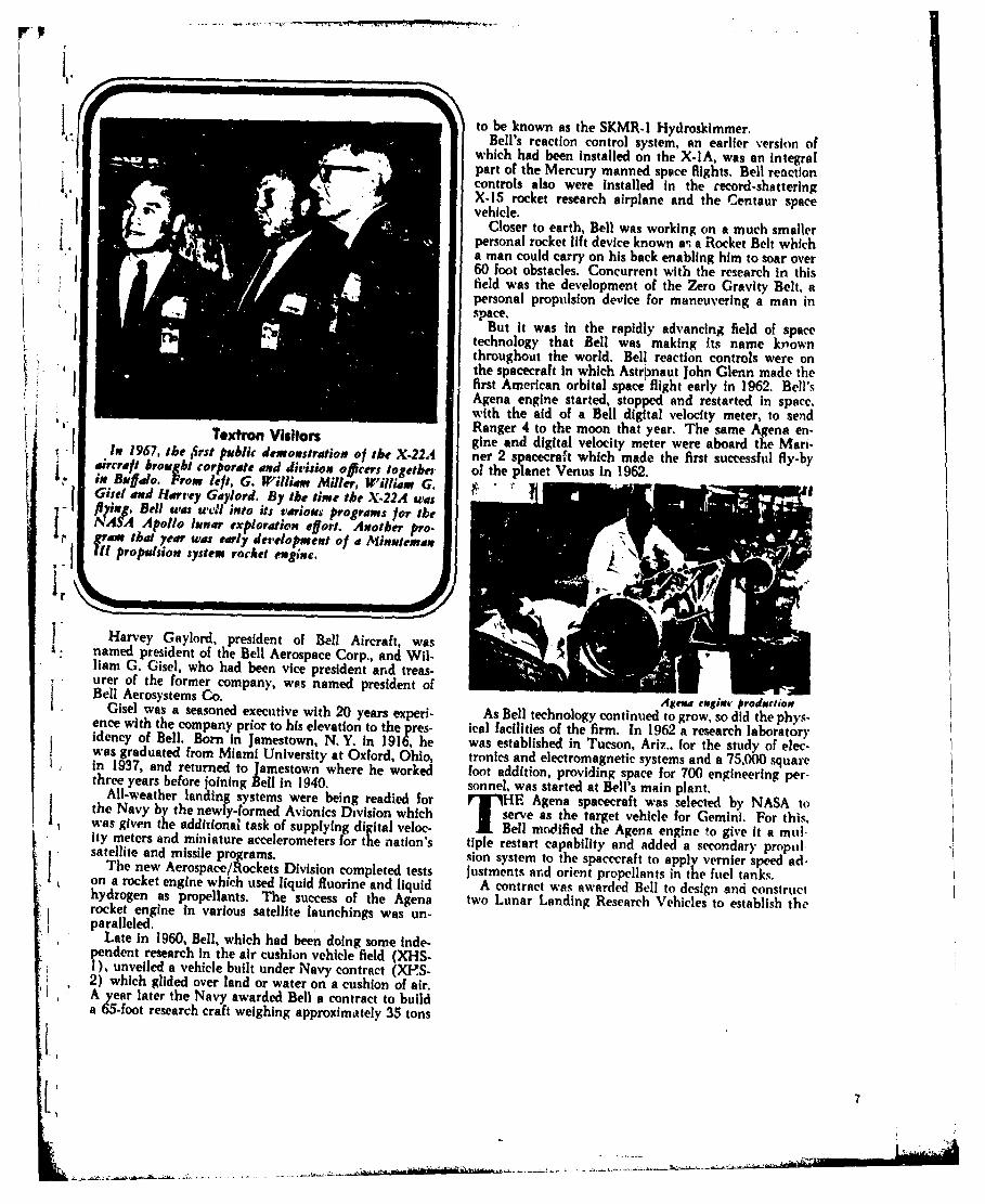
to be known as the SKMR-l Hydroskimmer.Bell's reaction control system, an earlier version ofwhich had been Installed on the X-IA, was an integralpart of the Mercury manned spece flights. Bell reactioncontrols also were installed in the record-shatteringX-15 rocket research airplane and the Centaur spacevehicle.
Closer to earth, Bell was working on a much smallerpersonal rocket lift device known a-, a Rocket Belt whicha man could carry on his back enabling him to soar over60 foot obstacles. Concurrent with the research in thisfield was the development of the Zero Gravity Belt, apersonal propulsion device for maneuvering a man inspace.
But it was in the rapidly advancing field of spacetechnology that Bell was making its name krownthroughout the world. Bell reaction controls were onthe spacecraft In which Astrbnaut John Glenn made thefirst American orbital space flight early in 1962. Bell'sAgena engine started, stopped and restarted in space.with the aid of a Bell digital velocity meter, to sendRanger 4 to the moon that year. The same Agena en-Toxtron Visitors gine and digital velocity meter were aboard the Mari-In 1967, the first public demonstration of the X-22.4 ner 2 s acecraft which made the first successful fly-byaircraft brougbt corporate and division officers togetbe, of the planet Venus In 1962.in Bewtfdo. lrom left, G. William Miller, W'illiam G.
Gisel and Harey Gaylord. By the time the X-22A wasArixg, Bell was u'el into its varioms; Programs for theA Apollo lunar exploration effort. Anotber pro.graw that year was early development of a MinuteananIII propsdsion system rocket engine.
Harvey Gaylord, president of Bell Aircraft, was - ,..named president of the Bell Aerospace Corp., and Wil-liam G. Gisel, who had been vice president and treas-urer of the former company, was named president ofBell Aerosysterns Co. AgeSm eseginc prodsictiowGisel was a seasoned executive with 20 years experi- As Bell technology continued to grow, so did the phys-ence with the company prior to his elevation to the pres- ical facilities of the firm. In 1962 a research laboratoryidency of Bell. Born in Jamestown, N. Y. in 1916, he was established in Tucson, Ari7.. for the study of elec-was graduated from Miami University at Oxford, Ohio, tronics and electromagnetic systems and a 75,000 squarein 1937, and returned to Jamestown where he worked foot addition, providing space for 700 engineering per-three years before joining Bell in 1940. sonnel, was started at Bell's main plant.All-weather landing systems were being readied for lHE Agena spacecraft was selected by NASA tothe Navy by the newly-formed Avionics Division which " serve as the target vehicle for Gemini. For this,was given the additional task of supplying digital veloc- T Bell mocified the Agena engine to give it a mu!-ity meters and miniature accelerometers for the nation's tiple restart capability and added a secondary propilsatellite and missile programs. sion system to the spacecraft to apply vernier speed ad-The new Aerospace/Rockets Division completed tests justments and orient propellants in the fuel tanks.on a rocket engine which used liquid fluorine and liquid A contract was awarded Bell to design and constructhydrogen as propellants. The success of the Agena two Lunar Landing Research Vehicles to establish therocket engine in various satellite launchings was un-paralleled.
Late in 1960, Bell, which had been doing some inde-pendent research in the air cushion vehicle field (XHS-) , unveiled a vehicle built under Navy contract (XRS-2) which glided over land or water on a cushion of air.A year later the Navy awarded Bell a contract to builda 65-foot research craft weighing approximately 35 tons
. 7
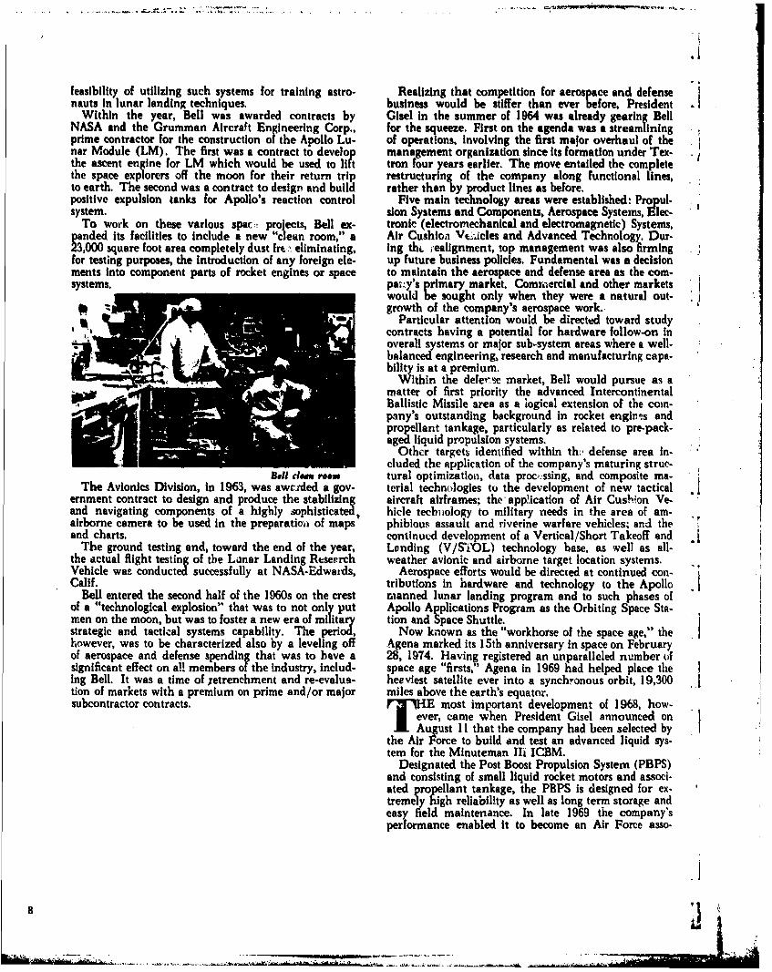
.1
feasibility of utilizing such systems for training astro- Realizing that competition for aerospace and defensenauts In lunar landing techniques. business would be stiffer than ever before, President
Within the year, Bell was awarded contracts by Glsel in the summer of 1964 was already gearing BellNASA and the Grumman Aircraft Engineering Corp., for the squeeze. First on the agenda was a streamliningprime contractor for the construction of the Apollo Lu- of operations, involving the first major overhaul of thenar Module (LM). The first was a contract to develop management organization since Its formation under Tex-the ascent engine for LM which would be used to lift tron four years earlier. The move entailed the completethe space explorers off the moon for their return trip restructuring of the company along functional lines,to earth. The second was a contract to design and build rather than by product lines as before.positive expulsion tanks for Apollo's reaction control Five main technology areas were established Propul-system. sion Systems and Components, Aerospace Systems, Elec-
To work on these various spac:- projects, Bell ex- tronic (electromechanical and electromagnetic) Systems,panded its facilities to include a new "clean room," a Air Cushioa VC-,icles and Advanced Technology. Dur-23,000 square foot area completely dust fre . eliminating, ing th. iealignment, top management was also firmingfor testing purposes, the introduction of any foreign ele- up future business policies. Fundamental was a decisionments into component parts of rocket engines or space to maintain the aerospace and defense area as the com-systems. pa..y's primary market. Comm~ercial and other markets
would be sought only when they were a natural out-It % growth of the company's aerospace work.,
Particular attention would be directed toward studycontracts having a potential for hardware follow-on inoverall systems or major sub-system areas where a well-balanced engineering, research and manufacturing capa-bility is at a premium.
Within the deferse market, Bell would pursue as amatter of first priority the advanced IntercontinentalBallistic Missile area as a logical extension of the coin-pany's outstanding background in rocket engn.ms andpropellant tankage, particularly as related to pre-pack-aged liquid propulsion systems.
Other targets identified within th., defense area in-eluded the application of the company's maturing struc-
BTh elA rom tural optimization, data processing, and composite ma-The Avionics Division, in 1963, was awttded a gov- terial technologies to the development of new tactical
eminent contract to design and produce the stabilizing aircraft airframes; the app ication of Air Cush]on Ve-and navigating components of a highly sophisticated, hicle techuology to military needs in the area of am-airborne camera to be used in the preparatioi of maps phibious assault and riverine warfare vehicles; and theand charts. continued development of a Vertical/Short Takeoff and - j
The ground testing and, toward the end of the year, Landing (V/STi'OL) technology base, as well as all-the actual flight testing of the Lunar Landing Reseprch weather avionic and airborne target location systems.Vehicle was conducted successfully at NASA-Edwards, Aerospace efforts would be directed at continued con-Calif. tributions in hardware and technology to the Apollo -
Bell entered the second half of the 1960s on the crest manned lunar landing program and to such phases ofof a "technological explosion" that was to not only put Apollo Applications Program as the Orbiting Space Sta-men on the moon, but was to foster a new era of military tion and Space Shuttle.strategic and tactical systems capability. The period, Now known as the "workhorse of the space age," thehowever, was to be characterized also by a leveling off Agena marked its 15th anniversary in space on Februaryof aerospace and defense spending that was to have a 28, 1974. Having registered an unparalleled number ofsignificant effect on a!! members of the Industry, includ- space age "firsts,' Agena in 1969 had helped place theing Bell. It was a time of retrenchment and re-evalua- heaviest satellite ever into a synchronous orbit, 19,300 .]tion of markets with a premium on prime and/or major miles above the earth's equator.subcontractor contracts. FIE most important development of 1968, how-
j ever, came when President Gisel announced onAugust 11 that the company had been selected by
the Air Force to build and test an advanced liquid sys-tem for the Minuteman 1i1 ICBM.
Designated the Post Boost Propulsion System (PBPS)and consisting of small liquid rocket motors and associ-ated propellant tankage, the PBPS is designed for ex-tremely high reliability as well as long term storage andeasy field maintenance. In late 1969 the company'sperformance enabled it to become an Air Force asso-
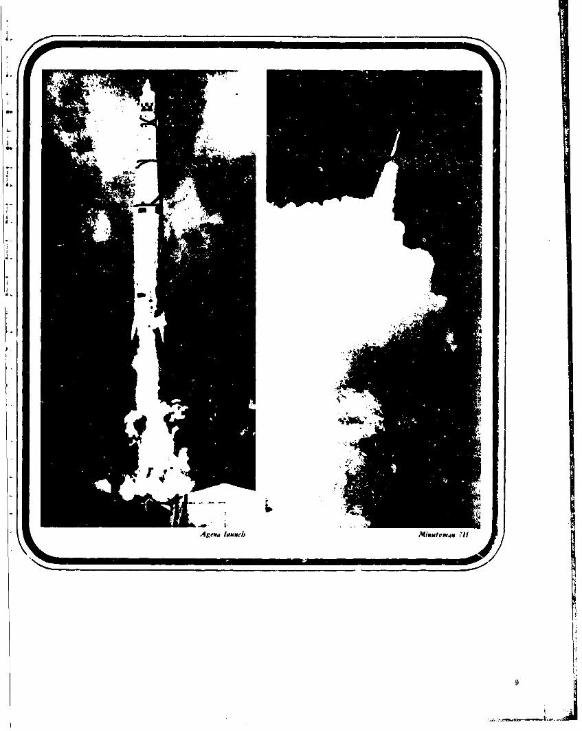
4-
A~ema Iis~geeb MiMNICW.IM h'lI
j~L j
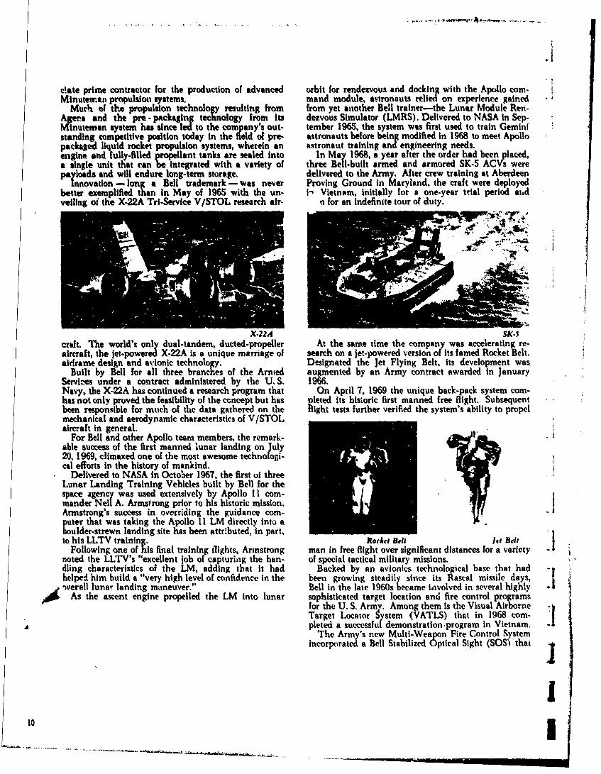
Ii
elate prime contractor for the production of advanced orbit for rendezvous and docking with the Apollo com-Minuteman propulsion systems. mand module, astronauts relied on experience gained
Much of the propulsion technology resulting from from yet another Bell trainer-the Lunar Module Ren-Agena and the pre -pickaging technology from its dezvous Simulator (LMRS). Delivered to NASA In Sep.Minuteman system has since led to the company's out- tember 196S, the system was first used to train Geministanding competitive position today in the field of pre- astronauts before being modified in 1968 to meet Apollopackaged liquid rocket propulsion systems, wherein an astronaut training and engineering needs.engine duly-fi propellant tanks are sealed into In May 1968, a year enteer had been placed,enieand fully-ied p Iatrteodrhdbe lcda single unit that can be integrated with a variety of three Bell-built armed and armored SK-5 ACVs werepayloads and will endure long-term storage. delivered to the Army. After crew training at Aberdeen
Innovation - long a Bell trademark - was never Proving Ground in Maryland, the craft were deployedbetter exemplified than in May of 1965 with the un- i- Vietnam, initially for a one-year trial period aitdveiling oi the X-22A Tri-Service V/STOL research air- n for an indefinite tour of duty.
X-22A SK.5crift. The world's only dual-tandem, ducted-propeller At the same time the company was accelerating re-aircraft, the jet-powered X.22A is a unique marriage of search on a jet-powered version of its famed Rocket Belt.airframe design and avionic technology. Designated the Jet Flying Belt, its development was
Built by Bell for all three branches of the Armed augmented by an Army contract awarded in JanuaryServic-es under a contract administered by the U. S. 1966.Navy, the X-22A has continued a research program that On April 7, 1969 the unique back-pack system com-has not only proved the feasibility of the concept but has pleted its historic first manned free flight. Subsequentbeen responsible for mtuch of the data gathered on the flight tests further verified the system's ability to propelmechanical and aerodynamic characteristics of V/STOLaircraft in general.
For Bell and other Apollo team members, the remark-able success of the first manned lunar landing on July20, 1969, climaxed one of the most awesome technologi-cal efforts in the history of mankind.
Delivered to NASA in October 1967. the first of threeLunar Landing Training Vehicles built by Bell for the rspace agency was used extensively by Apollo II corn-mander Nell A. Armstrong prior to his historic mission. -Armstrong's success in overriding the guidance com-puter that was taking the Apollo 11 LM directly into aboulder-strewn landing site has been attributed, in part, Ito his LLTV training. Rocet Bell let Belt [
Following one of his final training flights, Armstrong man in free flight over significant distances for a varietynoted the LLTV's "excellent job of capturing the han- of special tactical military missions.dling characteristics of the LM, adding that it had Backed by an avionics technological base that had -,helped him build a "very high level of confidence in the been growing steadily since its Rascal missile days,Sverall lunar landing maneuver." Bell in the late 1960s became involved in several highly .iAs the ascent engine propelled the LM into lunar sophisticated target location and fire control programs
for the U. S. Army. Among them is the Visual Airborne~Target Locator Sytem (VATLS) that in 1968 corn-|
pleted a successful demonstration program in Vietnam. .1The Army's new Multi-Weapon Fire Control System
incorporated a Bell Stabilized Optical Sight (SOS' that
10I10 . ..... ... .. .. .u . . .
.. . .. . .. . i I I I I I I I I I
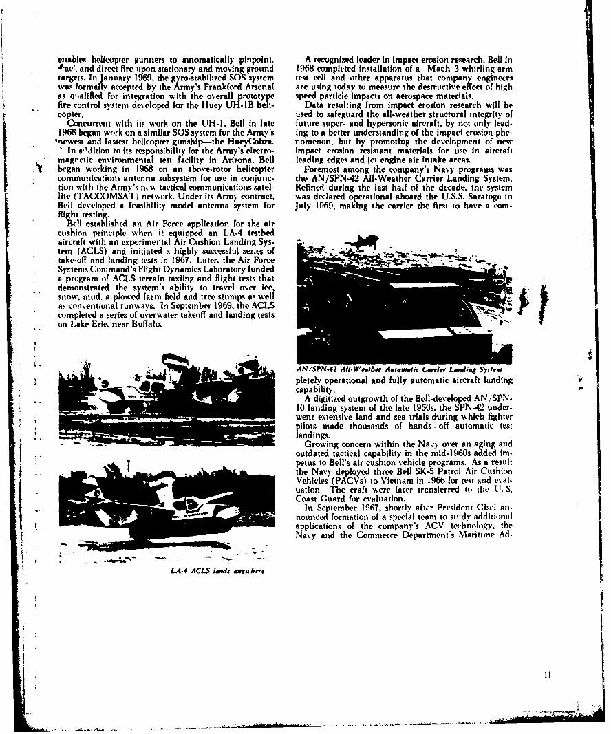
enables helicopter gunners to automatically pinpoint, A recognized leader in impact erosion research, Bell in*act-, and direct fire upon stationary and moving ground 1968 completed installation of a Mach 3 whirling armtargets, In January 1969. the gyro-stabilized SOS system test cell and other apparatus that companj enginecrswas formally accepted by the Army's Frankford Arsenal are using today to measure the destructive effect of highas qualified for integration with the overall prototype speed particle impacts on aerospace materials.fire control system developed for the Huey UH-B heli- Data resulting from impact erosion research will becopter, used to safeguard the all-weather structural integrity of
Concurrent with its work on the UH-I, Bell in late future super- and hypersonic aircraft, by not only lead-I968 began work on a similar SOS system for the Army's Ing to a better understanding of the impact erosion phe-
"newest and fastest helicopter gunship-the HueyCobra. nomenon, but by promoting the development of newIn aldition to its responsibility for the Army's electro- impact erosion resistant materials for use in aircraft
magnetic environmental test facility In Arizona, Bell leading edges and jet engine air Intake areas.began working in 1968 on an above-rotor helicopter Foremost among the company's Navy programs wascommunications antenna subsystem for use in conjunc- the AN/SPN-42 All-Weather Carrier Landing System.tion with the Army's new tactical communications satel- Refined during the last half of the decade, the systemlite (TACCOMSAI) network. Under its Army contract, was declared operational aboard the U.S.S. Saratoga inBell developed a feasibility model antenna system for July 1969, making the carrier the first to have a corn-'llght testing.tell est ablished an Air Force application for the air
cushion principle when it equipped an LA-4 testbedaircraft with an experimental Air Cushion Landing Sys-tem (ACLS) and initiated a highly successful series oftake-off and landing tests in 1967, Later, the Air Force -
Systems Command's Flight Dynamics Laboratory fundeda program of ACLS terrain taxiing and flight tests thatdemonstrated the system's ability to travel over ice,snow, mud, a plowed farm field and tree stumps as wellas conventional runways. In September 1969, the ACLScompleted a series of o\erwater takeoff and landing testson Lake Erie, near Buffalo.
ANiSPN-42 All-W'e gbev Atutomdtk Cerver Lumdig Systew
pletely operational and fully automatic aircraft landingcapability.
A digitized outgrowth of the Bell-developed AN/SPN-10 landing system of the late 1950s, the SPN-42 under-went extensive land and sea trials during which fighter, pilots made thousands of hands - off automatic testandings.
Growing concern within the Navy over an aging andoutdated tactical capability in the mid-1960s added im-petus to Bell's air cushion vehicle programs. As a resultthe Navy deployed three Bell SK-5 Patrol Air CushionVehicles (PACVs) to Vietnam in 1966 for test and eval-uation. The craft were later trensferred to the UT. S.Coast Guard for evaluation.
In September 1967, shortly after President Gisel an-nounced formation of a special team to study additionalapplications of the company's ACV technology, theNavy and the Commerce Department's Maritime Ad-
I. r . r lands abn,' ,--r-t• LA.,/ ACLS, Jduuds divyub¢rr
* II
:[ . ...
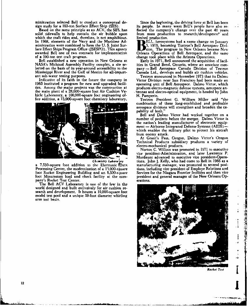
ministration selected Bell to conduct a conceptual de- Since the beginning, the driving force at Bell has beensign study for a 100-ton Surface Effect Sbip (SES). its people. In many ways Bell's peon le have al'ho re-
Based on the same principle as an ACV, the SES, has Hected the company's change over the past 40 yearssolid sidewalls to help contain the air bubble upon from mass production to research/development' andwhich the craft rides and, therefore, is not amphibious, limited production.In 1968, elements of the Navy and the Maritime Ad- B ELL Aerosystems had a name change on Jitnuaryministration were combined to form the U. S. joint Sur- 3, 190, becoming Textron's Bell Aerospace Divi-face Effect Ships Program Office (JSESPO). This agency B sion. The program in New Orleans became Ne\awarded Bell one of two contracts for implementation Orleans Oerations of Bell Aerospace, and the sameof a 100-ton test craft program, change too place with the Arizona Operations.
Bell established a new operation in New Orleans at Early in 1971, Bell announced the acquisition of facil-NASA's Michoud Assembly Facility complex, a site se- ities in Grand Bend, Ontario, where an associate corn-lected on the basis of its year-around accessibility to the pany - Bell Aerospace Canada Division of TextronMississippi River and the Gulf of Mexico for all-import- Canada Ltd., develops and builds air cushion vehicles.ant salt-water testing purposes. Textron announced in November 1973 that its Dalmo
Indicative of its faith in the future the company in Victor Division near San Francisco had been made an1965 instituted a program for new and upgraded facili- operating unit of Bell Aerospace. Dalmo Victor, whichties. Among the major projects was the construction at produces electro-magnetic defense systems, aerospace an-the main plant of a 28,000-square foot Air Cushion V- ,tennas and electro-optical equipment, is headed by Johnhicle Laboratory, a 100,000-square foot engineering of- H. Pamperin.fice addition, a 13,000-sq|iare foot chemistry laboratory, Textron President G. William Miller said "the
combination of these long-established and profitableaerospace divisions will strengthen and broaden the ca-pability of both."
Bell and Dalmo Victor had worked together on anumber of projects before the merger. Dalmo Victor isthe nation's leading manufacturer of electronic equip-ment - Airborne Integrated Defense Systems (AIDS)-which enables the military pilot to protect his aircraftfrom enemy attack.
At Grant's Pass, Oregon, Dalmo Victor's OregonTechnical Products subsidiary produces a variety ofelectro-mechanical products.
Norton C. Willcox was promoted in 1971 to executivevice president-Administration, and later Lawrence P.Mordaunt advanced to executive vice president-Opera-
Chemistry lborw ry tions. John J. Kelly, who had come to Bell in 1966 as aa 7,530-square foot addition to the Electronic ;ata manufacturing manager, was promoted to several posi-Processing Center, the modernization of a 13,000-suare tions, including vice president of Employe Relations andfoot Rocket Engineering Building and an 8,500-s,' uare Services for the Niagara Frontier fecilities and then vicefoot Minuteman load and check facility at the corn- president and general manager of the New Orleans Op-pany's Rocket Test Center. erations.
The Bell ACV Laboratory is one of the few in theworld designed and built exclsively for air cushion re-search and development. It houses a 10,000-square footmodel test pool and a unique 50-foot diameter whirlingarm test basin.
'ILI
. 1
Rorke$ Test j
12

New Orleans Operations DdIme Vi'ctor opevdtioul
MAzona Operationes Bell Aerospauce Caada
13
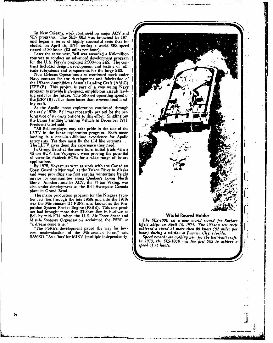
In New Orleans, work continued on major ACV andSE; programs. The SES-100B was launched in 1971and began a series of highly successful tests that In-cluded, on April 16, 1974, setting a world SES speedrecord of 80 knots (92 miles per hour).
Later the same year, Bell was awarded a $36-millioncontract to conduct an advanced development programfor the U. S. Navy's proposed 2,000-ton SES. The con-tract Included design, development and testing of full-scale subsystems and components for the large SES.
Ncw Orleans Operations also continued work under >'
Navy contract for the development and fabrication of ,the 160-ton Amphibious Assault Landing Craft (AALC)JEFF (B). This project Is part of a continuing Navyprogram to provide high-speed, amphibious assault lar4-Ing craft for the future. The 50-knot operating speed ofthe JEFF (B) is five timies faster than conventional lanlI-ing craft.
As the Apollo moon exploration continued through .the early 1970s, Bell was repeatedly praised for the per- Its..form',ce of its contributions to this effort. Singling out . -5,,the Lunar Landing Training Vehicle in December 1971,President Gisel said:
"All Bell employes may take pride in the roie of theLLTV in the lunar exploration program. Each moonlanding Is a oncu-in-a-lifetime experience for Apollo .astronauts. Yet they must fly the LM like veterans ...The LLTV gives them the experience they need."
In Grand Bend at the same time, initial trials with a , A e445-ton ACV, the Voyageur, were proviug the potentialof versatile, Patdeck ACVs for a wide range of future .k,,
applications.By 1975, Voyageurs w-re at work with the Canadian
Coast Guard in Montreal, at the Yukon River in Alaskaand were providing the first regular wintertime freightservice ior communities along Quebec's Lower NorthShore. Another. smaller ACV, the 17-ton Viking, wasalso under developmem: at the Bell Aerospace Canadaplant in Grand Bend.
The major production program for the Niagara Fron-tier facilities through the late 1960s and into the 1970swas the Minuteman III PBPS, also, known as the Pro-., .pulsion System Rocket Engine (PSRE). This one prod-uct had brought more than $700-million in busin~ess toBell by mid-1974, when the U. S. Air Force Space and World Record HolderMissile Systems Organization acclaimed the PSRE as The SES-IOOB set a new world record for Surface"a dream come true." Effect Ships on April 16, 1974. The 100-ton test craft
'The PSRE's development paved the way for low- achbeved a speed of more then 80 knots (92 miles percost modernization of the Minuteman force," said hour) during a mission at Panama City, Florida.SAMSO. "As a 'bus' for MIRV (multiple independently- Spced records are nothing new for the Bell-built craft.
In 1973, the SES-OOB was the first SES to achieve aspeed of 75 knots.
14,J
S-, .--

targeted reentry vehicle) payloads, PSRE has substan-tially increased the capability o! America's missile de- ,fense without the need for a large construcion program -to match the Soviet Union's numerical superiority in .. .ICBMs."
The U. S. Coast Guard operated two former Navy SK-5 ACVs in San Francisco for more than two years afterreceiving the craft in 1970, and found them to be versa-tile and cost effective. The craft were credited as "tvery effective means for solving nearly all mission demands" when combined with regular surface craft.
The Canadian Coast Guard was making si,'ilar dis-coveries with its ACVs, and added an ACV applicationthat had never been considered before-icebreaking.
R. G. Wade., superintendent for ACV engineering inCanada's Ministry of Transport, explained that theVoyageur was traveling at abott 15 knots over hard,unbroken ice when the crew noticed standing wavesabout four feet high were following the craft. The icewas violently cracking in these waves.
A year later, an ACV crew at Montreal used a Voya-geur to break up 3 ,-mile ice jam in a river north ofthe city, avoiding annual spring flooding in 1975. Prop-erties along the shore were saved an estimated $3-mil-lion in flood damage.
Among the major .,rgram under development atBell in the 1970s is the Microwave Landing System(MLS). Bell teamed with the Bendix Corporation in
p- 1971 t;. compete with nine original teams in develop-menit of the MLS for the Federal Aviation Administra-tion. In early 1975, the Bendix/Bell team had suc-ceeded in winning initial phases of the competition, and Pioneer on Icethe FAA was on its way toward ordering prototype MLS The Voyagesr ACV became ,v icebreaker by accident.systems from Bendix/Bell and a conretitor team headed .i Canadian Coast Guard/Ministry of Transport crewby Texas Instruments. was operatin; over ice in early 1974 wheu they dis-
In the early 1970s, Bell also entered a major new covered standing wavei following the craft - the ice wastechnology with great future potential - high energy rising up in "humps" and shattering viclently. Laterlasers. By 1975, the company was working under several trials added several additional icebreaking tecbiques,contracts for development of laser technology, including river icejam breaking. In the spring of 1973,
Through the years, first under Larry Bell and today more than $3-million in property damage caused by an-under President Gisel, Bell has continued its record of mud flooding was avoided becamse a 'oyageur leredapioneering achievements. On April ! 1, 1975, yet an- 311-mile icei am.other "first" was added when the 20-ton XC.8A aircraft,e.uIpped with an Air Cushion Landing System devel-oped mid built by Bell, made its first cushion landing.
The U. S. Air Frce at Wright-Patterson Air ForceBase, Ohio, termed the successful first tests "an Import-ant achievement it, the advancement of aerospace tech-nology.
Similar words could have been used nearly 40 yearsearlier when an airplane known as the Airacuda madeits first tests with a tricycle landing gear.
15
-- II. .... ..... .. . ... .. ~.. .. .. . ..I.... .... ,I. .... ... ..... . ... . .. .. . .. ,:. .... . . : 4- - ;- " :q "# i: ,

RONI the b, uindgig the k ill and dediatitoof its. p oleh h-we made Bell a pioneLering
leader. The meniv atnd woii of l.l Aerospace haw much toIx. proud of oil this .-1lh aitnilcrsary. Bell possesses the
technical know omw, the anagei eni t and the faacilities Itcositinuec its record of achievement in the future.
William G. Gisel
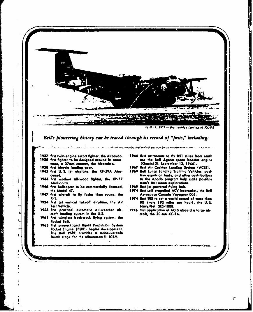
A4pil 11, 1971 - first fcvibeeas Idaeeiie of \C 14
*Bell's pioneering history can be traced through its record of "firsts," including:
~~~~ 77,"M- 77" -
1937 firat twin-engine escort fighter, the Alrocuda. 1966 fRst astronauts to fly 851 miles from earth1930 first fighter to be designed around Its arma- use the tell Agena space booster engine
mont, a 37mm cannon, the Airacobra. lGemini XI. September 13. 1966).*193I fIrst tricycle landing gear, 1967 firat Air Cushion Landing System I ACLS).
1942 first U. S. let airplane, the XP-59A Ar.- 1969 Bell Lunar Landing Training Vehicles, poi-comeot. tive expulsion tanks, and other contributions
1944 first modern al-wood fighter, the XP.77 to the Apollo program help n.ake possibleAirabonita. man's first moon explorations.
1946 first helicopter to be commercially licensed, 1969 first jet-powered flying belt.the Model 47. 1974 first self-propelled ACV kcebreake., the Sel
1947 first aircraft to fly faster than sound, the Aerospace Canada Voyageur 002.X. 1. 1974 first SES to set a world record of mnore than
1954 first let vertical takeoff airplane, the Air 80 knots 192 miles per hour), the U. S.Test Vehicle. Navy/tell SES. 100S.
1955 first practical automatic all-weather air. 1975 first application of ACLS aboard a large air-craft landing system In the U.S. craft, the 20-ton XC-SA.
1961 first wingless back-pack flying system, theRocket Belt.
1965 first prepackaged liquid Propulsion SystemRocket Engine I PSRE) begins development.The Bell PSRE provides a maneuverablefourth stat;* for the Minuteman Ill ICBM,
17
Division of Textton Inc
L.

ii
A
A
-- 4
I;
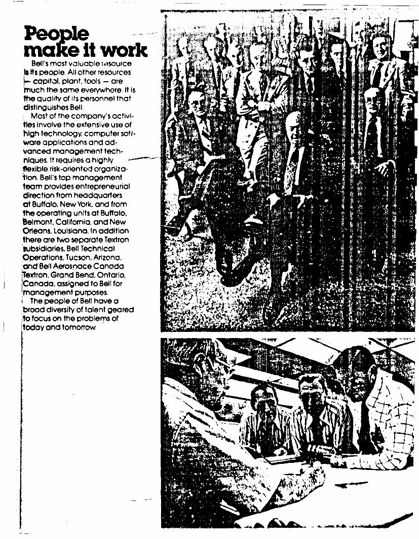
mUaet workBell's most valuable tesource
is Its people. All other resources- capital, plant, tools - aremuch the same everywhere. It isthe quality of its personnel thatdistinguishes Bell.
Most of the company's activi-ties Involve the extensive use ofhigh technology, computer sotl-ware applications and ad-vanced management tech-niques. It requires a highly -
flexible risk-oriented organiza-tion. Bell's top management
team provides entrepreneurialdirection from headquartersat Buffalo. New York. and fromthe operating units at Buffalo.Belmont, California, and NewOrleans, Louisiana. In additionthere are two separate Textronsubsidiaries, Bell TechnicalOperations, Tucson, Arizona,and Bell Aerospace CanadaTextron, Grand Bend, Ontario,iCanada. assigned to Bell formanagement purposes. :;,:-P?
The people of Bell have a .1- ' '
'broad diversity of talent geared .,to focus on the problems of ('.
today and tomorrow
101
%
, N
iIIIS
VV
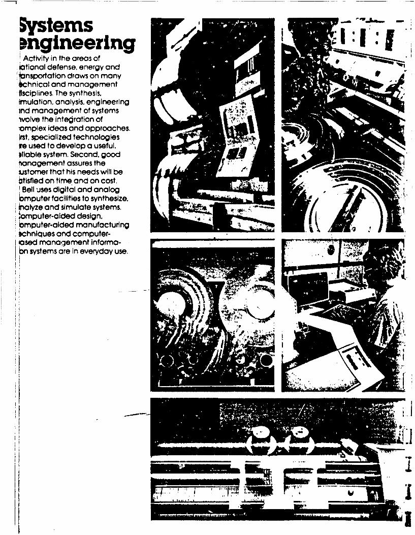
Systems 6
Activity in the areas ofiotional defense, energy andlonsportat ion draws on manybchnical and managementlisciplines. The synthesis.frnulatlon. analysis, engineeringind management of systemsivolve the intedration ofomplex ideas and approaches.Irst, specialized technologiesire used to develop a useful.illable system. Second. good 4
anagement assures theJustomer that his needs will beit Ife on time and on cost, NBellI uses digital and analog
b6mputer facilities to synthesize.alyze and simulate systems.,
lomputer-aided design.iomputer-aided manufacturingOchniques and computer-ased manorgement informa- .-
bn systems are in everyday use.
IWO..
--- fob A%
ILI
.~~ ........
4pS
-mm1
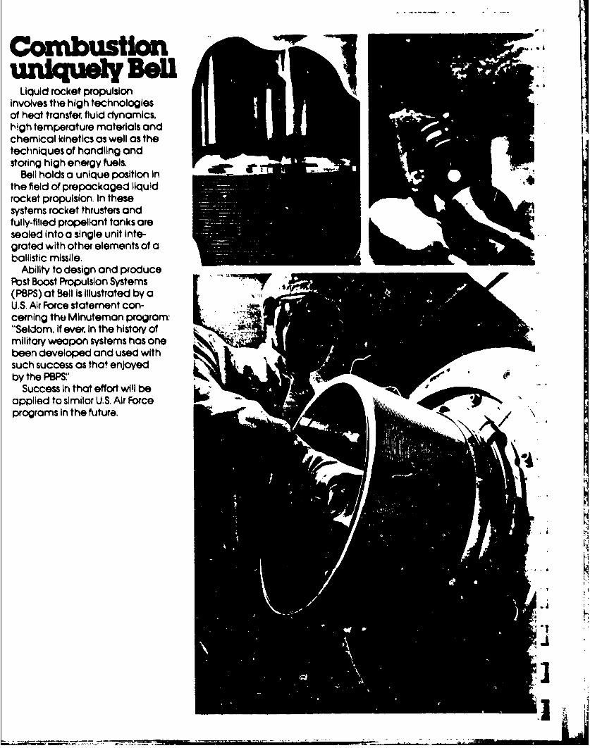
CombustionLiquid rocket propulsion
involves the high technologiesof heat transfer, fluid dynamics.high temperature materials andchemical kinetics as well as thetechniques of handling andstoring high energy fuels,
Bell holds a unique position inthe field of prepackaged liquidrocket propulsion. In thesesystems rocket thrusters andfully-fllted propellant tanks aresealed into a single unit Inte-grated with other elements of aballistic missile.
Ability to design and producePost Boost Propulsion Systems(PBPS) at Bell is illustrated by aU.S. Air Force statement con-cerning the Minuteman program:"Seldom, If ever, In the history ofmilitary weapon systems has onebeen developed and used withsuch success as that enjoyedby the PBPS' '
Success in that effort wi!l beapplied to similar U.S. Air Forceprograms In the future.
.1
* t
]
- " ' -'--- , R ... ... ... .... ... ........ ... -.... " - - ..- -'. :.::' J: - -

Ilk.
I

Combustionforwenergy
Beli innovation Is Illwutratedby the transfer of combustiontechnology to the critical areaof energy. With the demand forenergy Increasing while oil andgas supplies are diminishing,there is increasing pressure toconvert the notion's abundantsupply of coal Into a cleansynthetic fuel.
Bell Aerospace engineers areapplying rocket technology -injection and mixirg of fuels;c.," ialysis and contiol of chemicalreactions; design and fabrica-tion of hardware, and conductof test and evaluation programs- to develop high mass flux coalgasification systems. The gasproduced Is a low BTU fuel with ILpotential for electric power,industrial and chemical use. .:&.
.01'
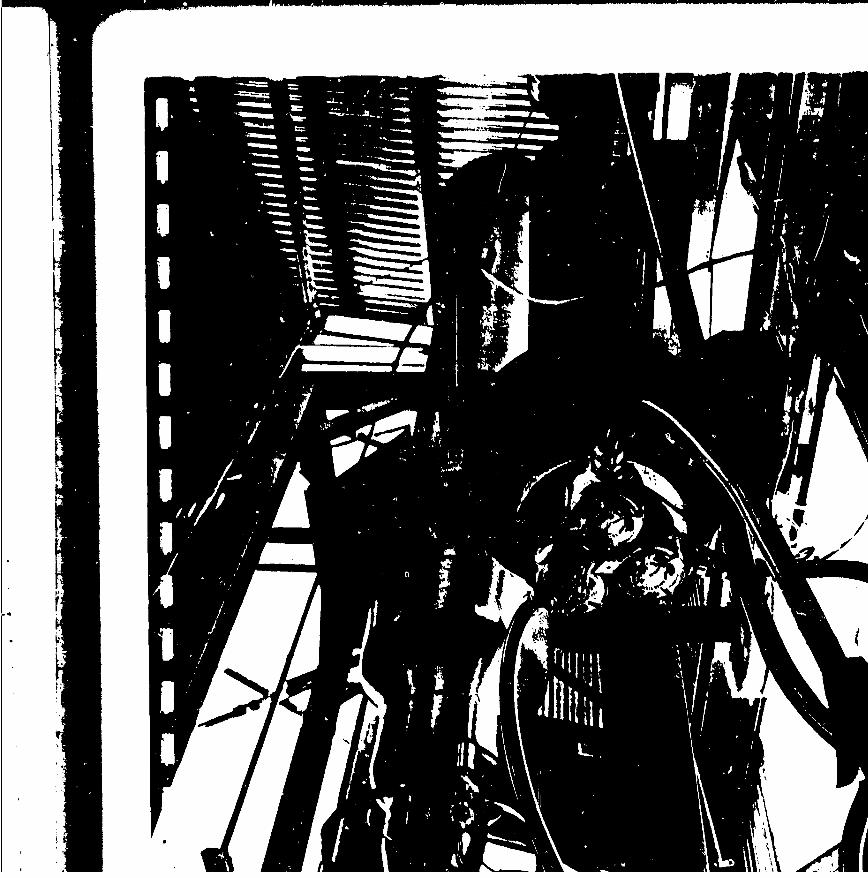
1411101,V~it. - /l -AIm* rm

Combustionbr losers
Another offshoot of thecombustion and chemicalsciences, which are part of liquidrocket engine work, is the highenergy chemical laser Theselasers are devices which use theenergies involved in chemicalreactions to produce a laserbeam which is many orders ofmagnitude more powerful thanthe small lasers being usedtoday commercially.
Bell's capability to developand use advanced fabricationtechniques, such as electro-forming and system synthusis,analysis and test has producedexperimental lasers among themost powerful in the world. Theeffort will permit Bell to producethe operational systems oftomorrow.

dk
9el

-Airi iills early dovelopmet of
V/STM aircraft expanded -.oInclude the potential of sup-portingvehces on acushion of
r nd eseoich and developmenthaegiven Bell engineers and
management an opportunityto closely study this newproduct line. W;
Ar cushion technology pro-6osamphibious and sea-
up to 100mph can skim over thesurface of the land, watm ice,snow, marsh and/or mud -conditions which plague con-ventlonal vehicles. Rapidly ad-vancing ACV technology requiresextensive use of advanced testteChniques In specialized facilitiesto confirm theoretical analysis ofoperating characteristics withvalid test data.
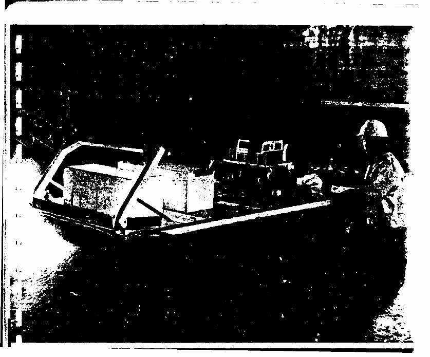
I 4. *pI
I
3 ..
-gA A ':*.
IA -~
I..
I '2
I
I A

Air cushionThe U.S. NOW'S Amphibious
Assault Landing Crc'ft Illustratesthe scope of Bell's Involvementin systemi engineering andmanagement of air cushion 'Itechnology Known as the 3JEFF(B), its lightweight, highstrength aluminum structurewas produced by advancedwelding techniques, Highefficiency, lightweight lift fanscombined with air distributionsystems and a flexible structureair containment and controlsystem comprise the core aircushion technology Theproject also drew on Bell ex-pertise in areas of marine gasturbines, transmission systems,high speed shafting. ductedpropellers and Integratedavionics systems. JEFF(B) dem-nnstrates the complete capa-bility to design and producemajor air cushion systems.
A
.|
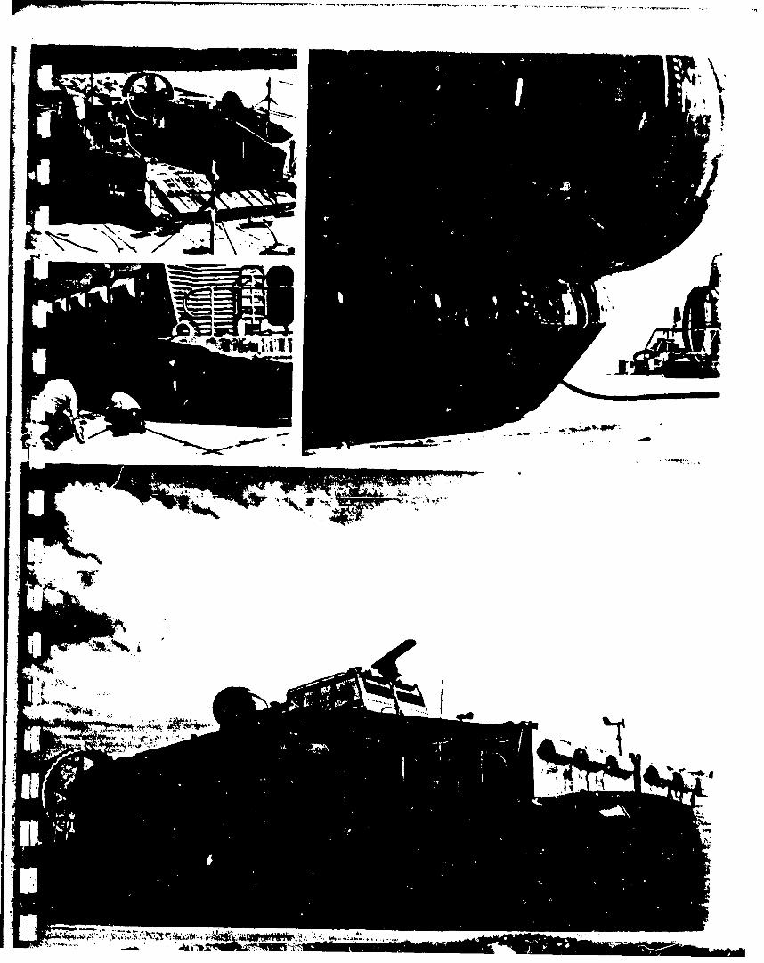
AILi
r ON.
St~ ~~~~i &A1 ,~w * '-

-II
Boats othermission
Each mission application ofBell's broadly based air cushiontechnology requires emphasison different engineerrg,disciplines,
A surface effect ship typecrew boat built by the Bell-Halter Joint Venture requiresemphasis on human tacto3 andhabitability to assure comfortand acceptance by civilianpassengers. Likewise, excellenthydrodynamic performance is
required for efficient, cost-effective
operation. Other variations area ferry boat and a lost patrol boat.
The Voyageur and its derivative .LACV-30 were designed for fully
amphibious. year-round mobilityfor logistics and Icebreakingoperations, Here the emphasis ,.
must be on rugged structuraldesign and reliable protectionfrom varied environments.
Bell's total systems capability " ...
enables the efficient combiningof disciplines common to Oilcraft. yet solving specific missionrequirements for each vehicle.
IA
116ddW d
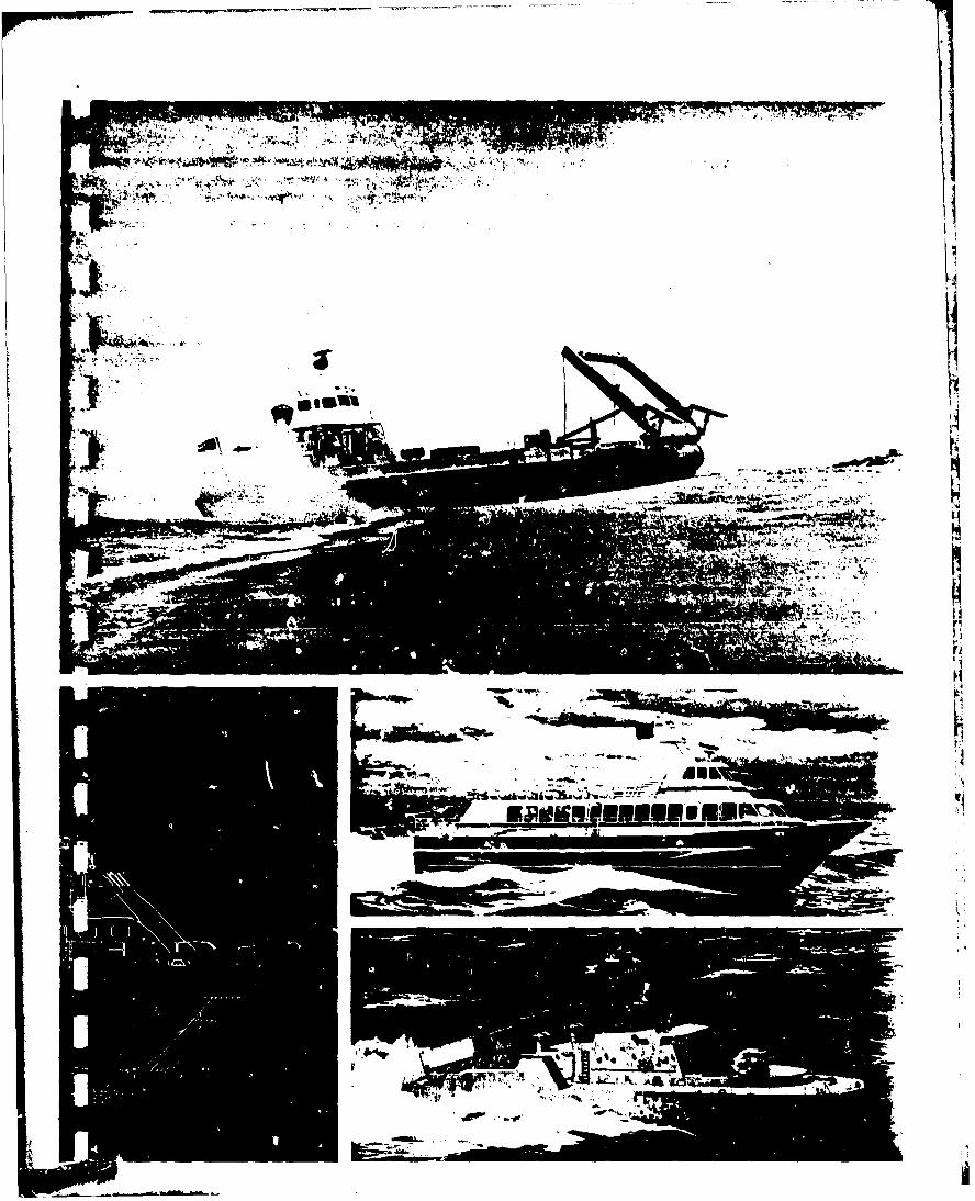
wmilli-V ---
ip AAlg v
lots
for defense-
most dyniamic technologies.IBell'., on~-going programs in
automatic aircraft landing,electronic warfare (EW) and I ainertial systems have kept itspeople and management inthe forefront ot these areas.
Military pilots using Bell elec-tronic warfare systems areprotected by equipment capa-
ble of analyzing a large numberof signals to detect threats. Bellis the nation's leader in design-Ing and producing high speed, -
software programmable EWdigital processors, Combinedwith its management capabilityto provide on time, on cost de-livery, the company maintains cnoutstanding position in this area. .
a-''E EIAV,
ALu.
o !2
$4W
For safelandings
Aircraft-oriented avionicssystems such as Bell's AutomaticAircraft Landing System requirea brInd spectrum of engineer-ing aisciolines. Aerodynamicand control factors of the air-craft, hydrodynamics of the ship,and the environmental factorsmust all be faultlessly combinedthrough precision electronicsand mechanics to safely landthe aircraft.
Bell has built automatic land-ing systems for more than 20years and continues today indevelopment of next genera-tion systems.
I ..
-/i,!'

I.
,* ,.~
FV
t
I
Instrumentsthat .7.get around
Past work on missile guidance .. ,systems has resulted in a capa-bility to develop and build highlyprecise, low-cost inertial Instru-ments for measuring velocity Inspace and the atmosphere. Inaddition this technology hasresulted In a line of gravity meters A
used to provide gravity maps ofthe ocean floor. Several oil com-panies a make use of these instru-ments to help detect oil deposits.
Bell has accepted the chal-lenges and has developed thecapability to design-to-cost andto total life-cycle cost. Engineersand management evaluateproven technologies againstnewer concepts to determinethe most cost-effective, reliable
and maintainable systems designto meet the customer's needs.
i ,7.

0 if A, 0 0 1 .0 0 f S
)0 jo p p 0 p A p p 0 ip 0 a 0 0 p v 1 4
44 qq 4% 1% qs,- IF lp ip p P P p jo 0 J p 0,0 1 p 1 .6 .1 -S I soA A I P P P 0 P P P P 0 0 P JO P lp s I V 0 0
0 0lk lk qk ek 0 0p p lp p jp p 0 0 Al 1 110.1
1 1 'D I I I -, p Aq .9 9 "a sk 41
1 41 % lk q q %q 49 41 44 4 4k wk 0 0 0 0 11 b 11 v v v 41 If .1 v
ir it 't 4r ir ikq % 4k 4 4tg w v c 11 r q 11 it %.4% q 44
;t 0 0 0 0 0 pp -p p 0 Ok 0 p b 11 10 11 qww go vs #8 to ##A v
I w two Owignuaq4t q 4 14 4 14 4 14 pippo19-41 PIF 49 q Ot 44 q q q 4 44 poop
4g q q *it 4 4414 44 4 Lit pop
v V 4p 9 At Air W W 9 a RA q R 4 44414444 0 is 1140 146 46494 ft 4 IN me
0 U 0 Ir 9 19 9 fAlp Ir ir w 19,q It q 4414 44 4 R. As
IL Pope IF pit Ooll* **IF lpf4 114 op;, O slesa sk lolls
404W4 4 f Ilot
Sol%
144AM44AAAAAAA a A
A444AAAAAAMS 10
.1" AMANAAAAAAAAAAA4 ' a A An a - a - AAA
AAAOAAAA,::afLLWLWLAAd%- AAAA"AA
""AAA AAM
4L & AAAAAC L
4.4L ILL
< 4K 0&4 -K, 4K IL 4(
t 49- 4( C 4K
d It 4( d' Ir
4, 4r wt -V -V ff
of SK 9 W OF I
dr Ol v 0 W dF p VVY
j oWfrww or IV IV at Ir
%VVIS
d 00001 11 Ts I,dddgdi Ts VSV I I
d Af 4 df 0 a welb too lot Wil 'a 11
4f W goo 4 of lldv 0 To Id If 0.610 M. Ot so: dvvviou
Is es d TA V. V V

Th.bu.damIn addition to its other tech-
nologles, Bell maintains a con-tinulng development effort inmetal processing. This supportsthe need for high strength struc-tures and minimum weight forsuch systems as air cushionvehicles, liquid rocket injectorsand nozzles, high energy lasernozzles and propellant tanks.Techniques such as electronbeam welding, plasma arc weld-Ing. laser welding MIG and TIGwelding are constantly beingImproved and expanded tonew and novel applications byBell manufacturing personnel.
I
''
4
~1
2.
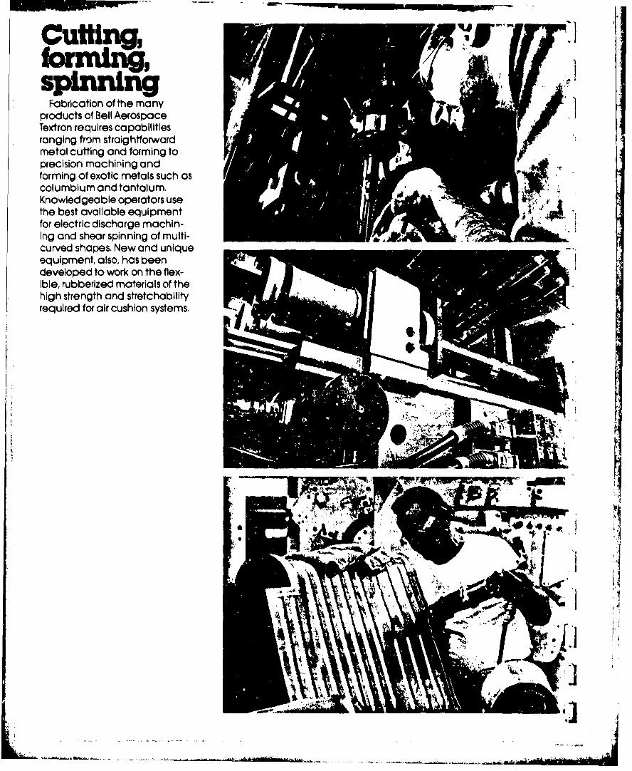
CUM-
Ctming,
spinningFabrication of the many
products of Bell AerospaceTextron requires capabilitiesranging from straightforwardmetal cuffing and forming toprecision machining andforming of exotic metals such ascolumblum and tantalum.Knowledgeable operators usethe best available equipmentfor electric discharge machin-ing and shear spinning of multi-curved shapes. New and uniqueequipment, also, has beendeveloped to work on the flex-ible, rubberized materials of thehigh strength and stretchabilityrequired for air cushion systems.
r
Ilk.
-" - -- - -----.

, .4"4,OZ' 4
illI-- I" K

The compan's engineeringand manufcturinlg capabiltiesare Supported by research lab-oratories in a wide range of fields,
from chemicals and metals to
fabrics and electronics, All Bell
products are backed by the COMn-
pany's product assurance organ-
sive and advanced computer
facility Bell has the capability to
evaluate,test and assure compli-
ance with every customeksneeds and design requirements,
Alj
,44.
]
kAI
ii
:.
lk-i
*
~1
Technology is a land unknown. No onecan tell where each new path will lead. Bellbegan with standard aircraft design. What Jhas been shown on these pages Is a partialpicture of the company's capability todayin widely diverse technologies. The bestmeasure of Bell's success In materlng andapplying these technologies Is itsaccomplishment. A partial list Includes:First U.S. jet airplane 9 First supersonic airplane* Firt licensed helicopter *First U.S. swept wing andvariable sweep airplanes * First jet V/STOL * LargestU.S. air cushion vehicle e First automatic all weatherlanding system e First air cushion landing systeme First digital electronic warfare 3ystem e First liquidpost boost p'opulislon system.
_..- .-

AkPPENiD C
BEtLL E6C~rp
U ~.wp.'LA
I 1I~fiiI~ijfv
r re
A2'
W.
s, q
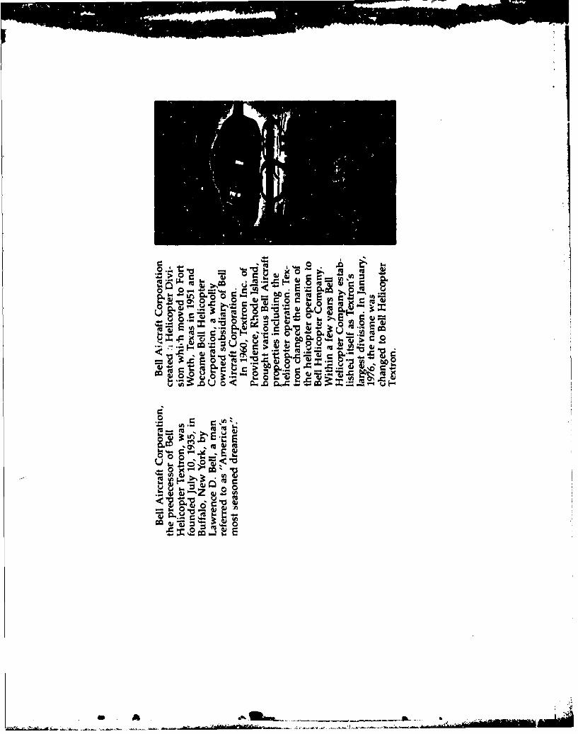
> 0 w 4
000z
5"0
- F- MZ Uj CJ 0c
E E
- ~~~ ~~ m ----.----.

C Ve 'a 9-~* ~ -
I. LM
la4 f . "
r0 0iID~ do 1~vu
'IOU qcm r:tb8 E- PI
ve ICU.
Iwo
jt -
*- Oz~~r,-
C 0 .
cc . Aa,
XN
~A)AAli
00
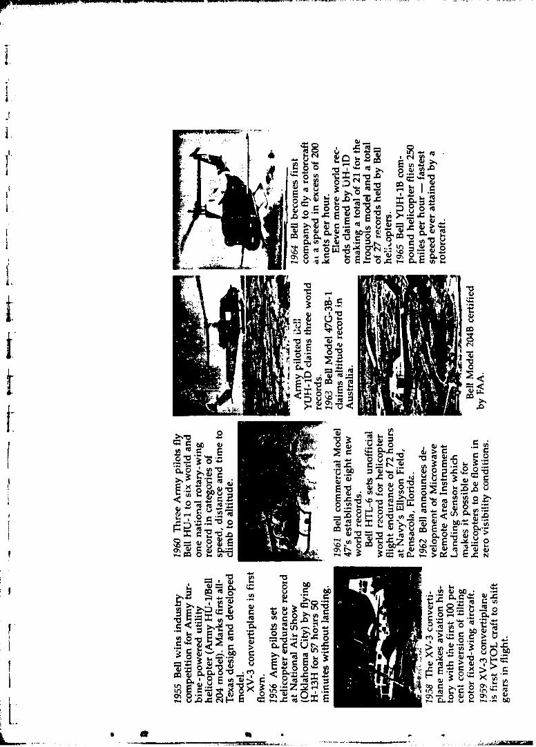
0 -0-
tnI w
C) >, (u 0. (c sm-= . 8r. o0*0 ".0w -= W E 0) . E, =
to- cc O.0 0. fu
c t TO- .to0I:."0 .;c0r_2
~C
~ ~ O>m ) 4 ) C o.
0 N~
M.9 C) Nb! , o-
0. to8 ~>, t v' '
o40 4: u 0~ -a 4
, m fuwoT
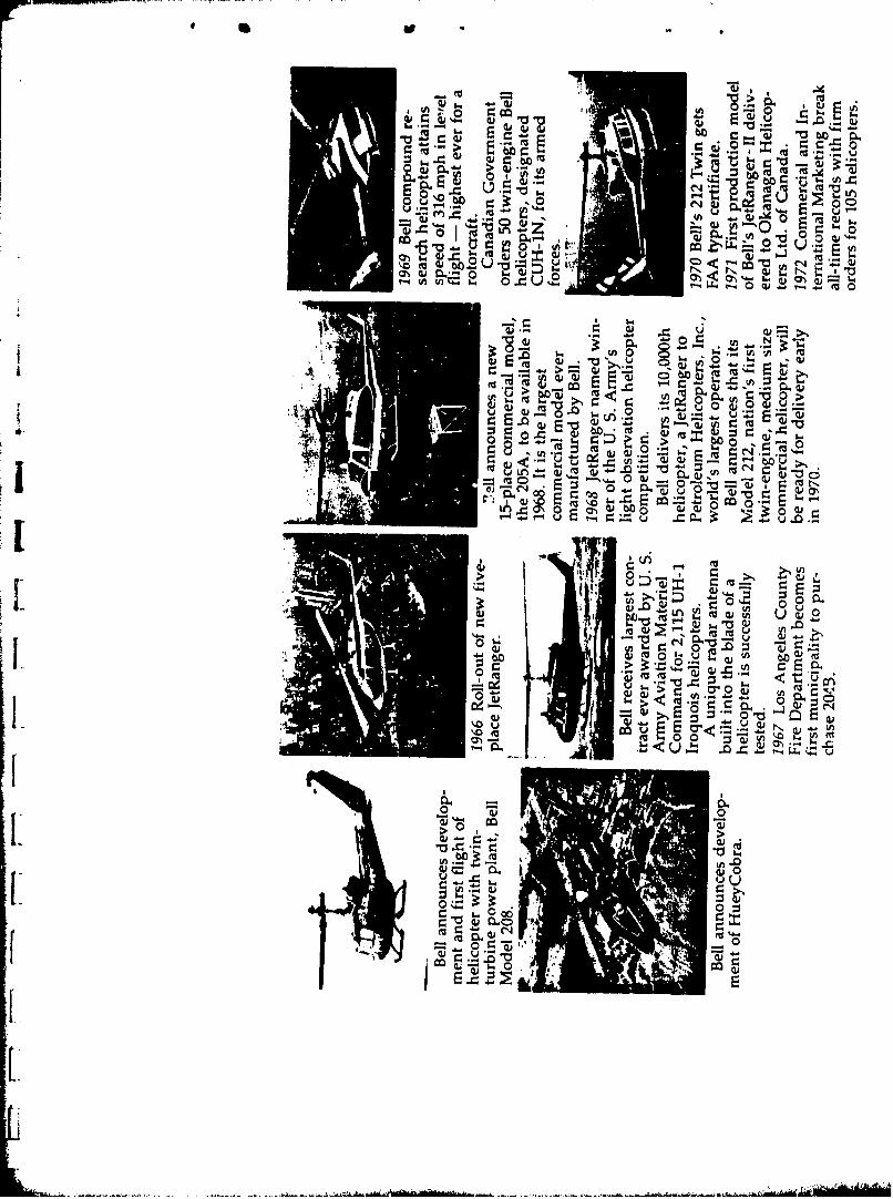
cu~ ,
E, C
r. O (Qj
~0 C,:
u c- -,0, tv -o-
m, ((u- EU
d C, tv E .3 W
0 EC
[ j uvE
wL c
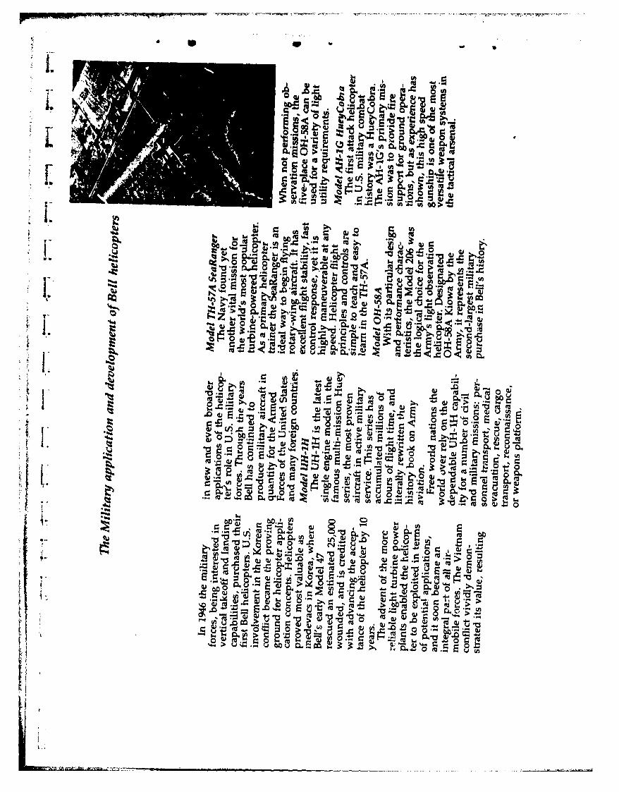
-- 5541~
M~
U) a -- 46 r. b~UNb
0 op
ck.04a - 0. ~* U ( - W
U , - CJ* MKIn:z . = o 0 E .
c 34
ow w os
to.- Ln(,U * ~ *wQ~ ICU
-0~'~ o1
'I Io
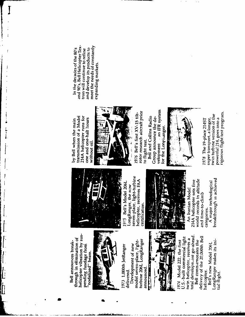
F0aI '
Q,
un U- 0-0-
I-JOJw.L U E
4 - u Q)0 0
H- x
Lu 0 0*
0 0-
0m 0jJ 0M.1 (ac
/'x Ez~o E
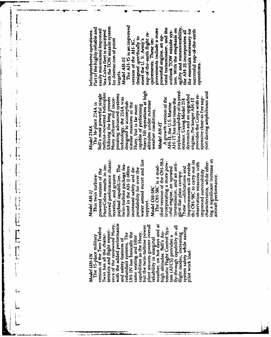
I.E 0
u.1.0
31 E . r' Eu ,o( 0- c-
e .4 " . w
w 0 (U
FC r.
'go (U -
E~~~~~. m.-4ne ,'.0--
(u(
aJ 9:6 v. E ~ ~ P. 0[~c ml. r. u U( .U.
.2~ E
toVD
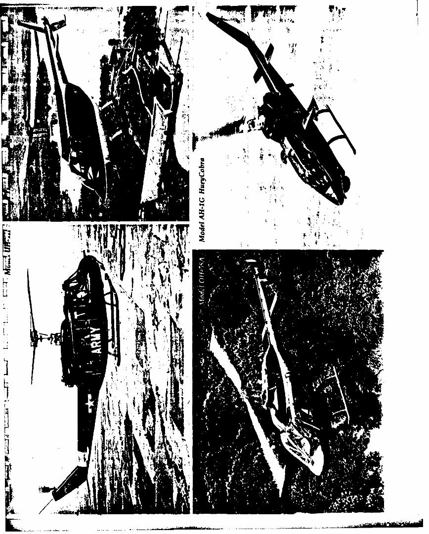
wr WE"IL~T
a / ~] *
I
~ 1*
a.a. . ~ ,*1~
-'V1~
a.
H ~ ,-I YI
- 4 4~I 'CV *~..
~ lBL a ~
ii I
A /A'S.
- ~ -*~..--.---
L 0
4 A
(A
_ U 4 b...V f
Il _ (U (
Ii o
.~ 0 h.
ch 0 :z EU(UU coz o. b c ,U w ,
N (U
C=-0 E -6 -0
> .-. E >
(U
(U ~ 0 cu OJ,,0
(u(u
*. o
0, .01Mr A-lu 0 4 A . U t

~'4'
~
-, - ''1w
-'I. -
3)
I ~
I, '~l--I1I
a,.
~jiw"*~ 4
Q~, '~
0
*"'t'
a4j#Y~,J ~
*
I,
- Y\\J
Li I 4~e
obe. - u
1- 'U
Z, E t ,
~M 0jII v 'r 41
0_ V3 _ 6 1 1
at'Am Z r
V) I1E.7.L 2i .Z( - c Q !
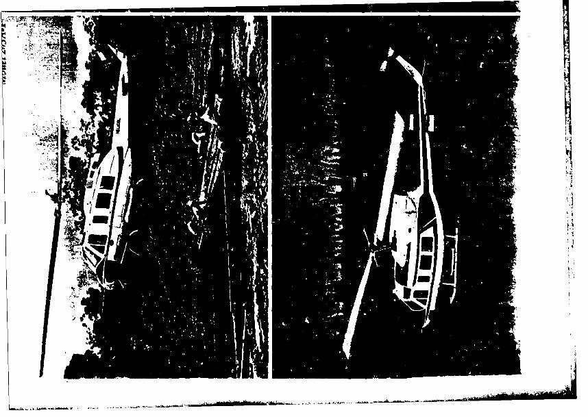
'-ar
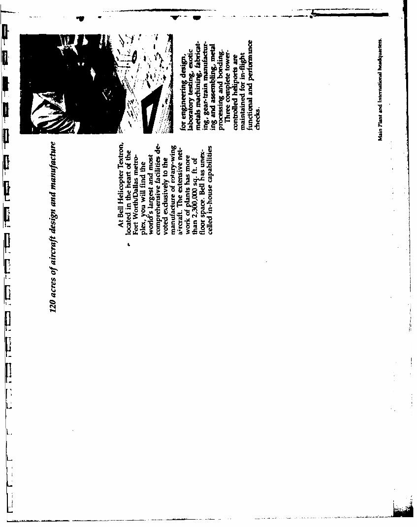
Uu a
II
v ic w 0D) . .vr~oM- 'lm4 )I! ~ a
0 O~
I~8

IV- -4f
-a.,.0 41 ,
I
-4 W14a
4w N~'Q
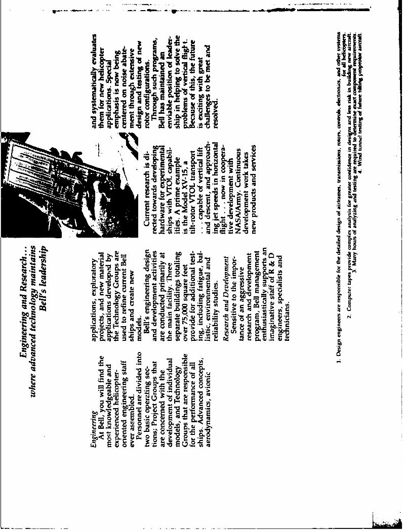
p _i
'Ago -a
1.. 1 Z~a citc
LA 4ca Et: -
-o 0
Z ,. is
~ (A2 C4 9. 2a
~(13
-Ow'
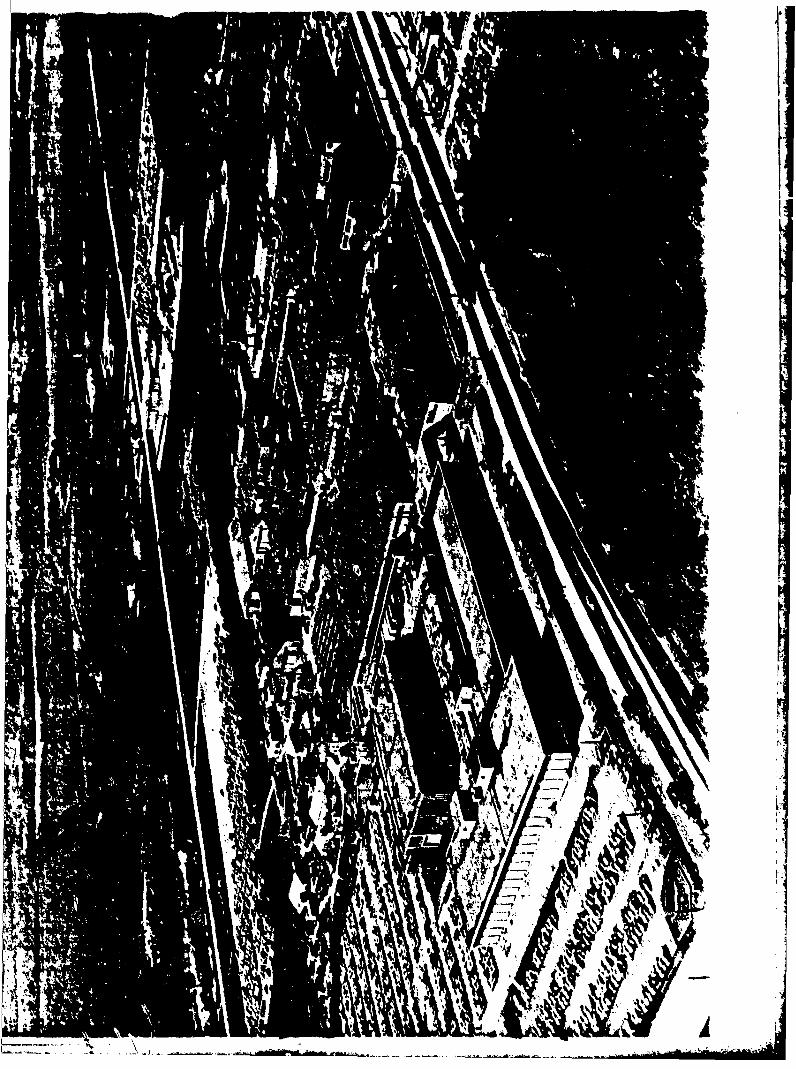
It..
.4
FfZc

NN 6
Aq ,0 Co~I>48 'Auc
.3 El
0.
fe m
0 (Z 0 C4j E
Wo.- w4 -* M 0) W
~CIO
va~'A SO
CL6-
C: 4 U~- (UU.,4
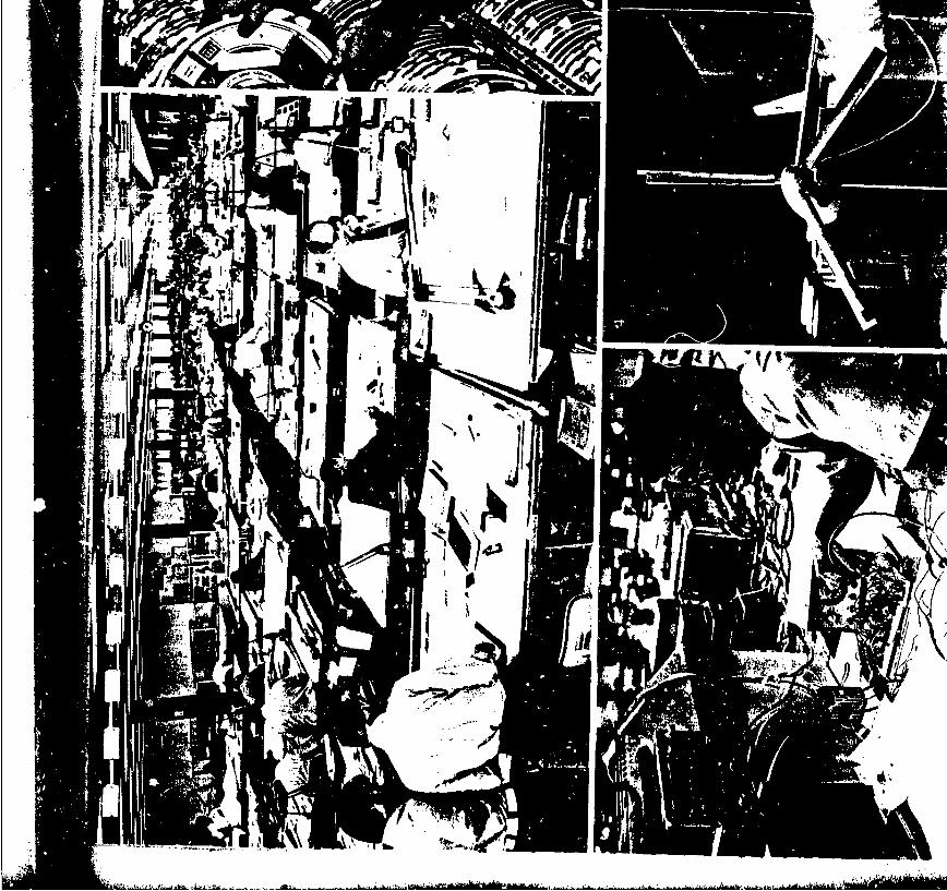
Ilk\
W Ji
- - ~kiiM~iUI~I~h~iI12

uLu
I Sm ".2 O
I - p(U6IMCU to 'A 0
I~~~ R~I~E
_ 0.2V.i (4 'o O
_f6 EU3
LL~
_ w*.-i 0 .~PC0 4,~cJ -A
Qj CU
~04
.~0.2
totg
U',,-
t pH-M Nus.
E. "D -:, r
11r
.0 V
r44
ccou
if .A-.'--'-
-E l
~ E 4 E
0f 0 waw~ ~ ~~ 4 E2u>
Bt i.. g ..l w -w~ wj o jc w O
441 *0U (u -0
~Eow o'-8 rbo
0 cl
1 -
~>
tf- 'r-
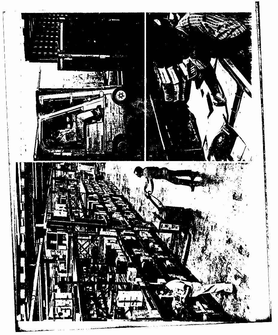
AM IV
Irv%-
j'A
vacnV~-Si 9j,.q
p *~W~4
W 4
.00C ~ ~ (2 :;, -
bCE
Pr.Ilk _U OOO
a 0
ml 0 to~(z. cnu m r (5
a a...
An 0
ta-
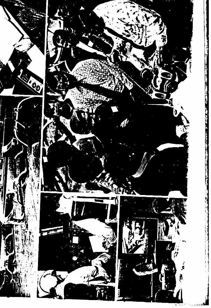
14'
I44
~l
~AdN
.4
____ Ed Aaerosm =zDMsion of Textro~n Inc.
APPENDIX D
BELL HELICOPTER TEXTRONMODEL 301 TILT-ROTOR AIRCRAFT
Bell Helicopter kirnii;Division of Textron Inc
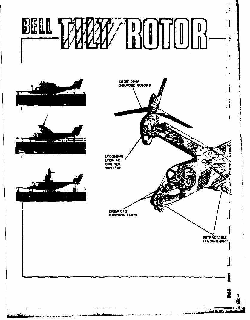
'(2 25' DIA- 34LADE MOTOR
I. LADEDROTOR
EJECTION SEATSI
RETRACTABLELANDING
GEAT'1
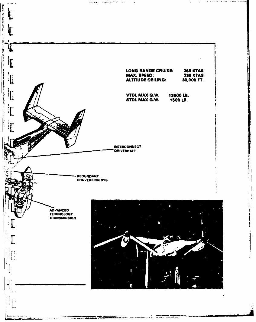
IE1LONG RANGE CRUISE: 266 KTASMAX. SPEED: 335 KTASALTITUDE CEILING: 30.000 FT.
'I.VTOL MAX G.W. 13000 LB.STOL MAXOGW. 1500OLa.
INTERCONNECTDRIVESHAUT
* ~ . REDUNDANT
CONVERSION SYS.
ADVANCEDTECHNOLOGY[ TRANSMISSIONI
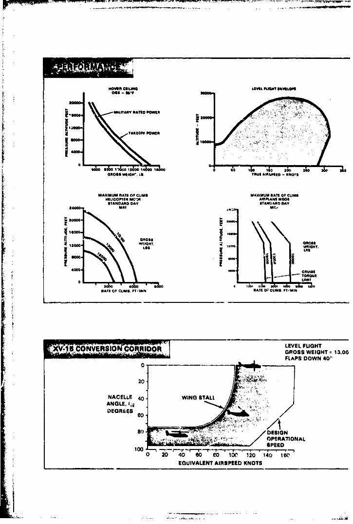
move" liumeLEEL FLIGHT INVELOPS
MILITARY RATIO 0 ON 0
TAKEOFF POWER V
GROSS WEIGH'. LB. TRUE AIRAPSED -KNT
MAXIMUM RATE OF CLIMB MAXIMUM RATE OF CLIMBWEUICOOPTER M0*3f AIRPLANE MOO&
STANDARD DAY STANbANOt DAY2400 MR!, Mf.e
20000.
GRUOSS anoSS1200 - LbST
am.o
4000 CRUISE
J LIMIT
RATS Of CLIMB. FT/MIN RATE P~CLIMI. FT'MIN
NV 'ERS ONLEVEL FLIGHT
Q'nRIDORGROSS WEIGHT 13.00FLAPS DOWN 40"'
20I
NACELLE 40- WING STALLANGLE. 1,4 .
DEGREES
OPERATIONAL
0 20 40 60 eo 100 120 140 1 WEOUIVALENT AIRSPEED KNOTS
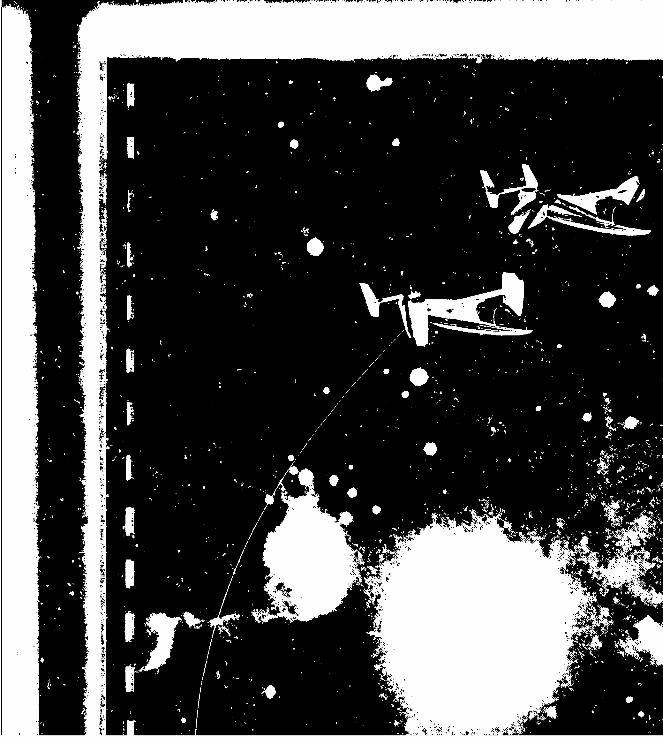
-741
41

Model 301Tilt Rotor
Aircraft....A Product of Research
In April 1973, the National Aeronautics and Space The Model 301 Tilt Rotor Aircraft has a design grossAdministration and the United States Army announced weight of 13,000 pounds and a maximum grossthat Bell Helicopter Company was selected to design weight of 15,000 pounds. It can hover out-of-ground LIand manufacture two tit-rotor research aircraft. The effect at 7700 feet with both engines or on a singlevehicle Bell will build, designated the Model 301, is engine at sea level. Cruise speeds will exceed 300designed to explore, through flight research, the knot: in level flight and 360 knots in a shallow dive.state of tilt rotor technology and its potential in civil Each wing tip nacelle contains a Lycoming LTC1K-4K
and military missions, engine. This engine, designed to permit vertical oper- rPrimary research objectives for the NASA/Army pro. ation, has a normal rating of 1290 SHP and a takeoff jgram are contained in a series of proof-of-concept rating of 1550 SHP. A 2 minute rating at 1760 SHPtests designed to investigate the technical value of will permit a range of testing under single enginethe tilt rotor concept. Dynamic stability and aircraft conditions. 'iperformance over the entire operational envelope willbe evaluated to verify the prediction methods used The model 301 utilizes a rotor and transmission sys.in analyses. tem designed and fabricated under a Bell IR&D pro-A safe operating envelope will be established and gram. Design -characteristics include a forward-sweptassessment of handling qualities will be conducted for high wing, a clean fuselage with retractable landing
advanced flight research. Noise, gust sensitiVity, and gear, and a !arge volume H-tail. For the researchmaintenance characteristics will be explored, phase, crew ejection seats are incorporated. 3
I--
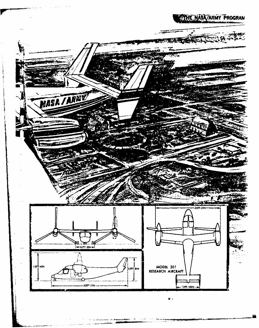
-5 T-1 --- --
na
ASAIAP 10T 31-
13FT41N-a-. 12TM OE 0
REEACHAICRF
- . da..'4--.--- -' * ,-.-
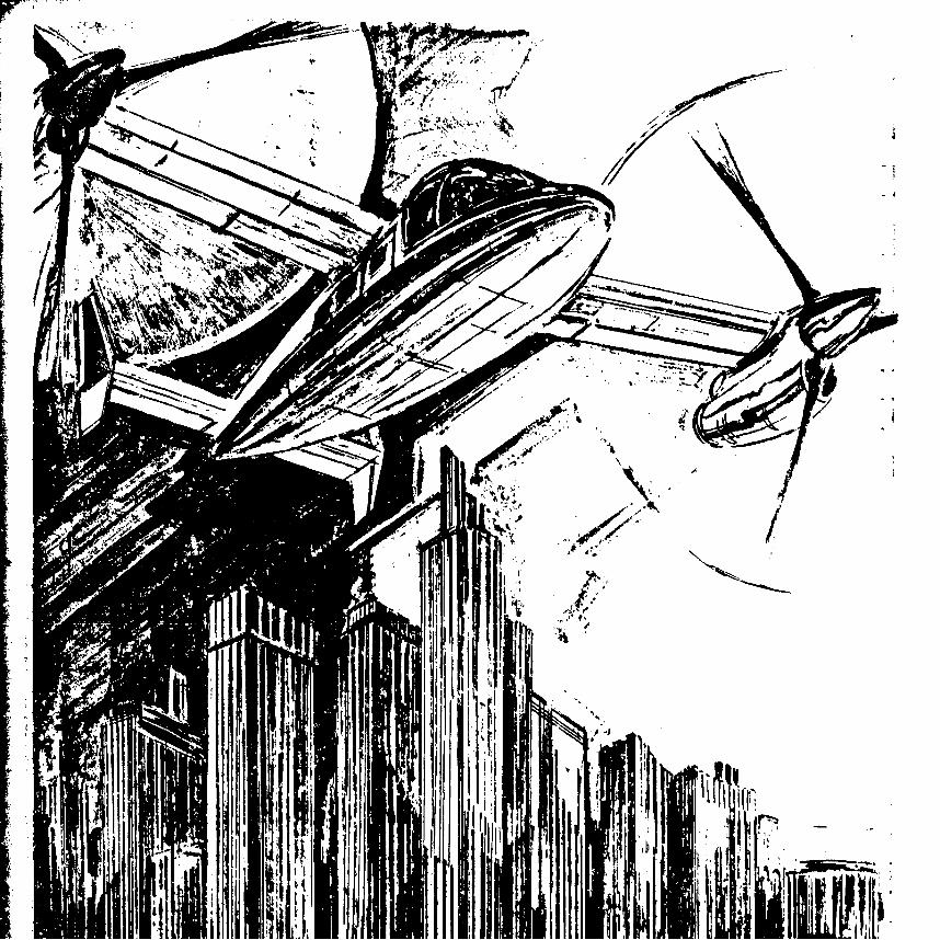
Tv/jjkh-
r'.Ar
40 ,-4
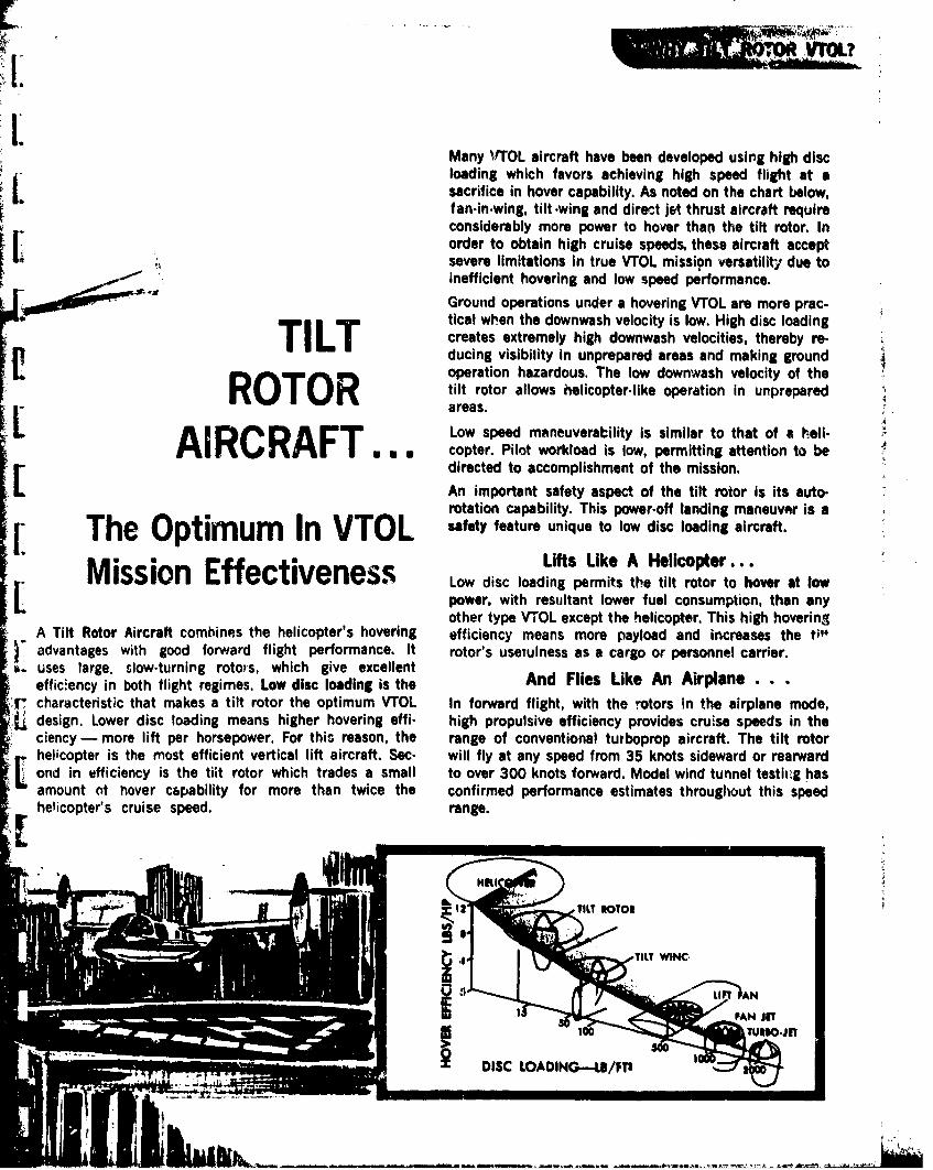
II.4Many 1'TOL aircraft have been developed using high discloading which favors achieving high speed flight at asacrifice in hover capability. As noted on the chart below,fan-in-wing, tilt -wing and direct jet thrust aircraft requireconsiderably more power to hover than the tilt rotor. Inorder to obtain high cruise speeds, these aircraft acceptsevere limitations in true VTOL mission versatility due toInefficient hovering and low speed performance.
Ground operations under a hovering VTOL are more prac-tical when the downwash velocity is low. High disc loadingTILT creates extremely high downwash velocities, thereby re-ducing visibility in unprepared areas and making groundoperation hazardous. The low downwash velocity of the
tilt rotor allows helicopter-like operation in unpreparedareas,
LA I RA FT Low speed maneuverability is similar to that of a heli-AIRA FT . copter. Pilot workload is low, permitting attention to bedirected to accomplishment of the mission.An important safety aspect of the tilt rotor is its auto-rotation capability. This power-off landing maneuver is a
The Optim um In VTOL safety feature unique to low disc loading aircraft.
Miss n Es ,Lifts Like A Helicopter...isi on Ev Low disc loading permits the tilt rotor to hover at low
power, with resultant lower fuel consumption, than anyother type VTOL except the helicopter. This high hovering
- A Tilt Rotor Aircraft combines the helicopter's hovering efficiency means more payload and increases the ti'" advantages with good forward flight performance. It rotor's useTulness as a cargo or personnel carrier.1r. uses large. slow-turning rotos, which give excellent
effic-ency in both flight regimes. Low disc loading is the And Flies Like An Airplane,'f characteristic that makes a tilt rotor the optimum VTOL In forward flight, with the rotors in the airplane mode,:L design. Lower disc loading means higher hovering effi- high propulsive efficiency provides cruise speeds in the
ciency - more lift per horsepower. For this reason, the range of conventional turboprop aircraft. The tilt rotorL helicopter is the most efficient vertical lift aircraft. Sec. will fly at any speed from 35 knots sideward or rearwardond in efficiency is the tilt rotor which trades a small to over 300 knots forward. Model wind tunnel testii'g hasamount ot hover c6pability for more than twice the confirmed performance estimates throughout this speedhelicopter's cruise speed. range.
[3
--- ~~1 T--L"T " ROTOR
tI..
DISC LOADING-LSB/FTI
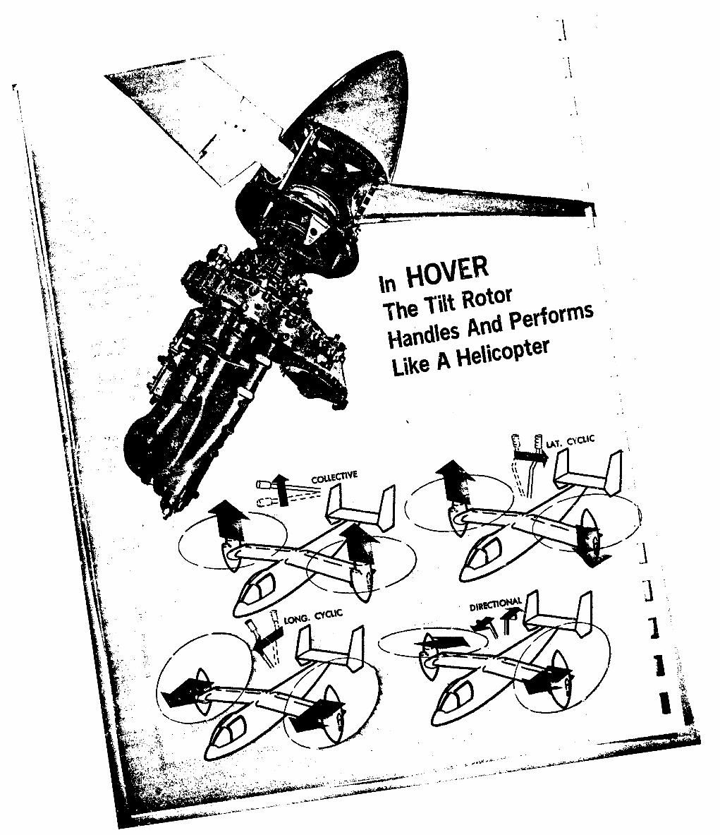
VAVE
V aJ1 ~LLEC!W CWCU
I. 'ONO. CIC.ICI
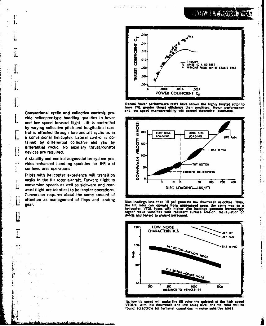
.016UA
.012
L .)
.010 - THEORY
M r € AMES 40 X 10 TEST
.006
L C .00 .0616 .0624POWER COEFFICIENT Cp
Recent hover performaice tests have shown the highly twisted rotor tohave 7% greater thrust efficiency than predicted. Hover performance
Conventional cyclic and collective controls pro. and low speed maneuverability will exceed theoretical estimates.
ji vide helicopter-type handling qualities in hoverand low speed forward flight. Lift is controlledby varying collective pitch and longitudinal con-trol is effected through fore.and-aft cyclic as in Z -200- LOW DISC HIGH DiSCa conventional helicopter. Lateral control is ob. LOADING LOADING LANtained by differential collective and yaw bydifferential cyclic. No auxiliary thrust/control TIdevices are required. >
A stability and control augmentation system pro. mvides enhanced handling qualities for IFR and > TILT ROTOR
confined area operations. so-3t CURRENT HELICOPTERS
Pilots with helicopter experience will transitioneasily to the tilt rotor aircraft. Forward flight to I • i's i 160 2 4&conversion speeds as well as sideward and rear-ward flight are identical to helicopter operations. DISC LOADING--LS$/FTConversion requires about the same amount of IIIIIIattention as management of flaps and landing Disc loadlrgs less than 15 pst generate low downwash velocities. Thus,gear. the tilt rotor can operate from unprepared areas the same way as a
helicopter. VTOL types with higher disc loadings generate Increasinglyhigher wake velocities with resultant surface erosion, recirculation ofdebris and hazard to ground personnel.
120 LOW NOISECHARACTERISTICS LIFT JET:' " LIFT PAN i
100. 11* TILT WING
rst
DISTANCE TO VEIICL--PT
Its low tip speed will make the tilt rotor the quietest of the high speedVTOLs. ith low downwash and low noise level, the tilt rotor will befound acceptable for terminal operations in noise sensitive areas.
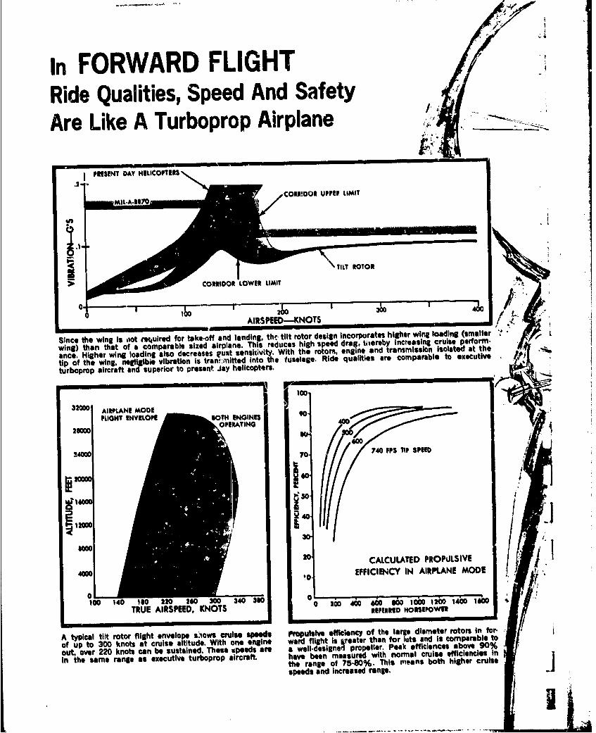
in FORWARD FLIGHTRide Qualities, Speed And SafetyAre Like A Turboprop Airplane
PRESENT DAY HELICOPTERS
> ~CORIDOR LOWER LIMIT
AIRSPEED-KNOTS
Since the wing is oot mecuired for take-off and landing. thc- tilt rotor design Incorporates higher wing loading (smaller ~wing) then that of a comparable sized airplane. This reduces high speed drag, tiereby increasing cruise perform-
ane. Higher wing loading also decreases grust sensitivity. With the rotors, engine, and transmission isolated at the
tip of the wing. negligibie vibration Is trans :nitted into te fuselage. Ride qualities are comparable to executive /D
turboprop aircraft and superior to present Jay helicopters.
AIRPLANE MODEFLIGHT ENVELOE0T ENGINES 90-
2=0 RtATING26000
24000 70. 740 FPS TIP SPEED
650
00Moo so I
100 1440 20 203043
RELCELRED ROPOIE
A yia410 rtrfih0nvlp ~oscus pes i'plieefcee ftelag imtrrtr nfr
ofin the t same r ranght eneuverop r ops creft.md ha~ve enmaue ihn a rie efficiencieftelag imeeoo s In r
the range of 75-80%. This means both higher cruise
speeds and Increased range.
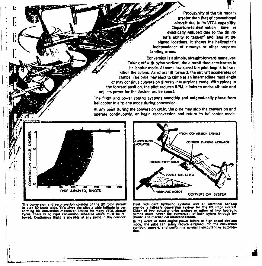
.Produccivty of the tilt rotor is;greater than that of conventional
aircraft duc. to Its VTOL capability.[eparture-to-destination time is
drastically reduced due to th. tilt rotor's ability to take-off and land at do-i; signed locations. It shares the heliconter's
independence of runways or other preparedlanding areas.
I_ Conversion is a simple, straight-forward maneuver.. Taking off with pylon vertical, the aircraft then accelerates in
f helicopter mode. At some low speed the pilot begins to tran-.ition the pylons. As rotors tilt forward, the aircraft accelerates or
climbs. The pilct may elect to climb at an interradiate mast angleor may continue conversion directly into airplane mode. With pylons in
the forward position, the pilot reduces RPM, climbs to cruise altitude andadjusts power for the desired cruise speed.
The flight and power control systems smoothly and automatkilly phase fromhelicopter to airplane mode during conversion.
/ At any point during the conversion cycle, the pilot may stop the conversion andoperate continuously, or begin reconversion and return to helicopter mode.
0"LON CONVERSION SPINDLECONVII$ON ONTOL PMASING ACTUATOR
ACTUATOR
INTERCONNECT HNAFT -..
DOUSI& ALL SCRr-Y
0 40 so 11o 160 2W0 240 2oTRUE AIRSPEED, KNOTS YDVAULIC MOTOR
CONVERSION SYSTEM
The conversion and reconversion corridor of the tilt rotor aircraft Dual redundant hydraulic systems and an electrical bak-upis over 80 knots wide. This gives the pilot a wide latitude in per- provide a fall-safe conversion system for the tilt rotor aircraft.forming his conversion maneuver. Unlike for many VTOL aircraft Either of two actuator drive motors or either of two hydraulictypes, there is no rigid conversion schedule which must be fol- pumps could power the conversion of both pylons through hy-lowed. Continuous flight is possible at any point in the corridor. draulic and mechanical interconnections.
In the event of total engine power failure In high speed airplanemode, the pilot can safely reduce airspeed into the conversioncorridor, convert, and perform a normal helicopter-like autorota-tion.

-4 o4
BEGINN-I~r iBeofOre The~ XV . .
i 14
Be'*ll, the Onlyr 4company to consistently pursue and supportthe til rjor conep, brings over 25 Years of testing,analyses, design, flight test experience and hardware tothe Model 301 tilt rotor program.In 1951, Bell received a contract to build the XV-3 tiltrotor aircraft under a joint Air Force.Army program. Over100 successful convtr0s.o 5 were made in 125 hours offlight tests. The aircraft PCOved the concept feasibilityand safety features inherent to the design.For the Model 301, several Years Of analyss model test.ing, and devell 'pment and testing of critical componentshas gradually reduced the program risk.* Full-scale flight.jworthy rotor& and transMisslo,
5 have been thoroughlyand successfully tested.Over 15 separate Model and full-scale wind tunnel testsJhave beenl coniucted to determ.ine the aerodynamnic andaeroelastic parameters necessary to complete the designOf the tilt rotor aircraft.All necessary work Prior to final detail aircraft design hasbeen Coflplated.

*Bell's 25 YearsOf Tilt RotorExperience Is Focused
[ On The Model 301
A CHRONOLOGY OF TILT ROTOR PROGRESS
I PSIGNIANALYSES TILT ROTO
j - - t ~TORMMG & P~GTEST
VERNUENT TI
~E) TOM STABILITYI. ANALYSIS
In e late 1940's, Setl egan to develoo th technology which I to a SA Ytw ship prototype can ertiplane program i 1951. The joint Ai Force-Army tVED
I.XV aircraft demonst ted concept feasibi ty and ease and saft of theco ersion sequence. e first full cosivers ns were made in D ember 1956.Fu power-off reconve ions, autorotations and landings were ado Iosrrfol- wing simulated en mne failures. AIRCEiIn 965, the Army initi ted the Composite ircraft Program in ich tilt POR
In 68, an in-house d velopment progra or the analysis and esign ofo raein n piain eesuiL4Hltilt otor aircraft desig ted the Mode' 300 as initiated. Also i that year, 5 IIESBe began developrre t of advanced cor nefnts for the tilt tor aircraft. WIND TUNNEL TESTI.In 970, a flightworth rotor was fabricat and tested, both in ne powered AEROELASTIC MODElS(a dynamic) and un wered (aeroelastic modes in NASA's x80 wind
*-tu el at Ames. FLIGHT WORIn 972, under NASA/ rmy contract ,Bell t sted a 1/5 scale dy mic model ofth Bell Model 300 Air rft (a lower-power version of the M 1 301).Hi and low speed wi tunnel tests in fr n and in air have n conducted.Ea y in 1973, Bell con octed a whirl test o the Wright Field W irl Test Tower NOLADYof e full-scale rotor nder a NASA/Ar contract. Result indicate that mNSMISSIONpr icted performanc ata in hover were nservative.
NASAIARMY PROS
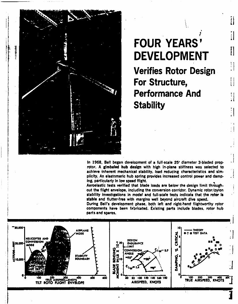
FOUR YEARS'DEVELOPMENTVerifies Rotor DesignFor Structure,Performance AndStability
In 1968, Bell began development of a full-scale 25' diameter 3.bladed prop.rotor. A gimbaled hub design with high in.plane stiffness was selected toachieve Inherent mechanical stability, load reducing characteristics and sim.plicity. An elastomeric hub spring provides increased control power and damp.ing, particularly In low speed flight.Aeroelastic tests verified that blade loads are below the design limit through.out the flight envelope, Including the conversion corridor. Dynamic rotor/pylonstability Investigations in model and full.scale tests indicate that the rotor isstable and flutter.free with margins well beyond aircraft dive speed.During Bell's development phase, both left and right.hand flightworthy rotorcomponents have been febricated. Existing parts include blades, rotor hubparts and spares.
AIIPLAN0 - IONY
/MOD 1 0 0 8EST DATANMtlCOPTHN AND DISION 9l
o0o 10 120n IDUWANCI. -M as INS
€OCLN,,, , SA 2W 0,0Ile0I
0 C100 Soo 30 0
TILT ROTO FLIGHT ENVLOPI ARSPD. KNOTS TRUE AIRSPEED. KNOTS
I I I I I
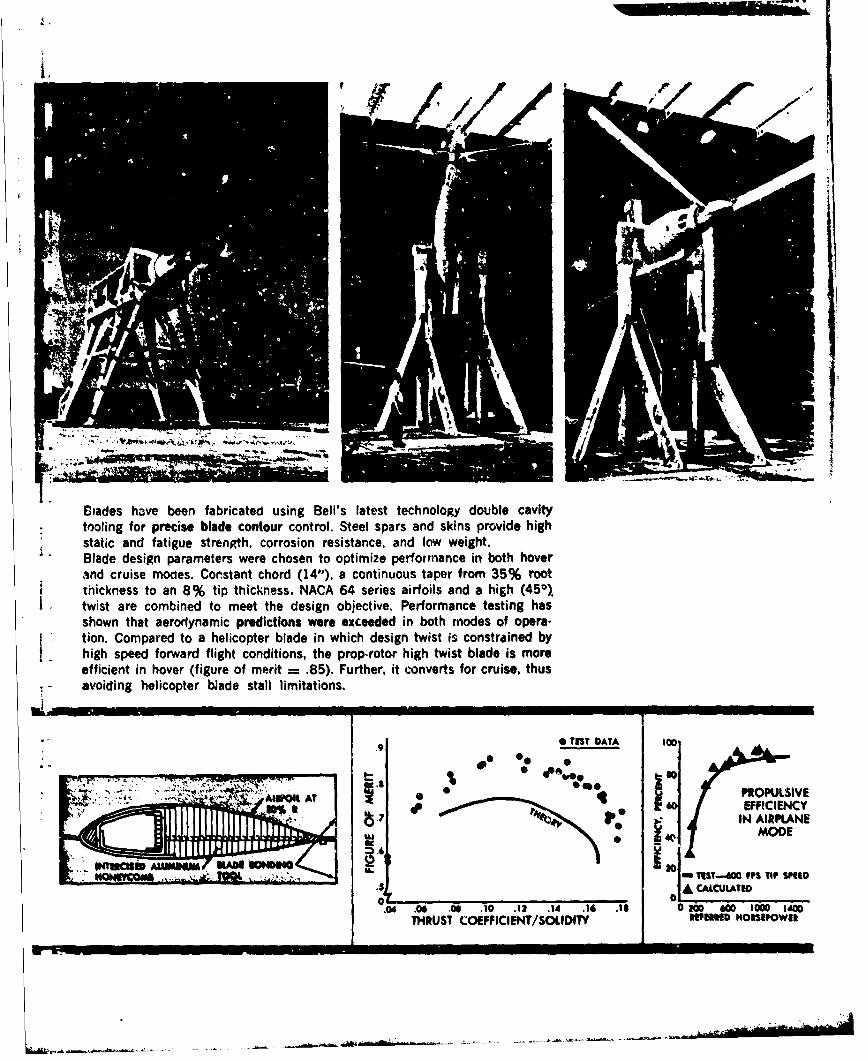
BMades have been fabricated using Bell's latest technology double cavitytooling for precise blade contour control. Steel spars and skins provide highstatic and fatigue strenRth, corrosion resistance, and low weight,Blade design parameters were chosen to optimize performance in both hoverand cruise moaes. Constant chord (14"1). a continuous taper from 35% rootthickness to an 8% tip thick-ness. NACA 64 series airfoils and a high (450).twist are combined to meet the design objective. Performance testing hasshown that aerodynamic predictions were exceeded in both modes of opera-tion. Compared to a helicopter blade in which design twist is constrained byhigh speed forward flight conditions, the prop-rotor high twist blade is moreefficient in hover (figure of merit = .85). Further, it converts for cruise, thusavoiding helicopter bJade stall limitations.
0 TEST DATA too,
"0.0 PROPULSIVE
AI00A 140 EFFICIENCYI,. IN AIRPLANE
MODE
KANW. 1201 I-TEST-41W UPS TIP SPEED' ~~~~0 A' C "': " ••ALCULATED
THRUST COEFFICIENT/SOLIDITY muPtWm "OIPOWER
7, - I II I- I I
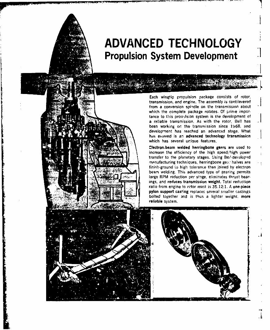
ADVANCED TECHNOLOGYPropulsion System Development
Each wingtip propulsion package consists of rotor,transmission, and engine. The assembly is cantileveredfrom a conversion spindle on the transmission aboutwhich the complete package rotates. Of p~rire impor-tance to 1his prooilsion system is the development ofa reliable transmission. As with the rotor, Bell hasbeen working or the transmission since 1968, anddevelop-ient has reached an advanced stage. Whathds eoived is aq advanced technology tralsmissicnwhich has several urique features.
"lectron.beam welded herringbone gears are used toincrease the efficiency of the high speed/high powertransfer to the planetary stages. Using Bei'-developdmpnufacturing techniques, herringbone ge&-; ' halves arefinish-ground 'o high tolerance then joined by electronbeam welding. This advanced type of gearing permitslarge RPM reduction per stige, eliminates thrust bear-ings, and reduces transmission weight. Total reductionratio from engine to rotor mast is 35.12:1. A one-piecepylon support casting replaces several smaller castings
bolted together 3nd is thus a lighter weight, morereliable system.
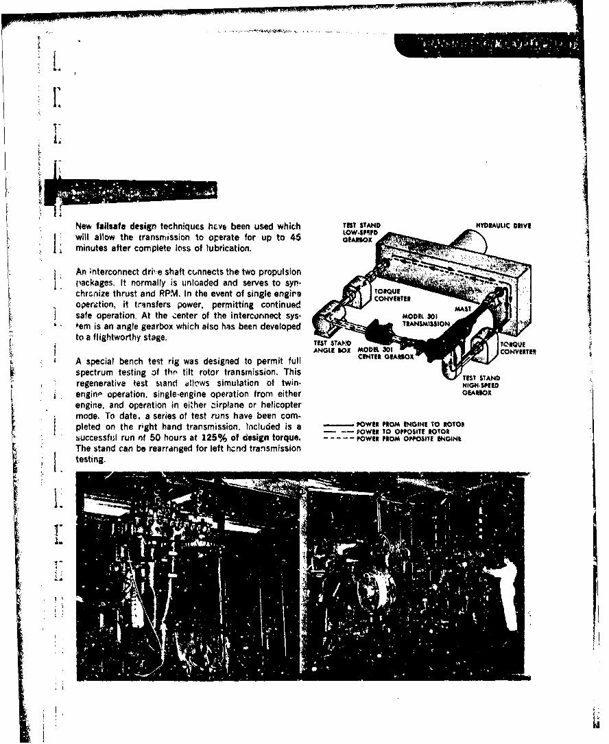
L.
New failsafe design techrnqucs h~ve been used which TEST STAND HYDRAULIC DRIVEwlallow the transmission to Operate for up to 45 GEARBOX
minue after complete loss of lubrication.
An ;nterconnect drib e shaft connects the two propulsionS packages, It normally is unloaded and serves to syn.
chronize thrust and IRP.M. In the event of single engire I U., operiation, it transfers power, permitting continued MASTVREsafe operation, At the :enter of the interconnect Sys.MOE30
L ' fern is an angle gearbox which also lhas been developedto a flightworthy stage.TETSADORU
A special bench test rig was designed to permit full CENTER GEARBOXTE
spectrum testing of thf, tilt rotor transmission. Thisregenerative test siand allo'ws simulation of twin. HIGH-SPEED
i enginp operation, single-engine operation from either GEARSOXengine, and operation in either z-irplane or helicoptermodle. To date, a series at test runs have been com-pleted on the right hand transmission. Included is a -POWER FROM ENGINE TO ROTOR
P - OWER TO OPPOSITE ROTORsuccessful run nf 50 hours at 125% of design torque.-------POWER PROM OPPOSITE ENGINkThe stand can be rearranged for left hznd tran'smission
testing
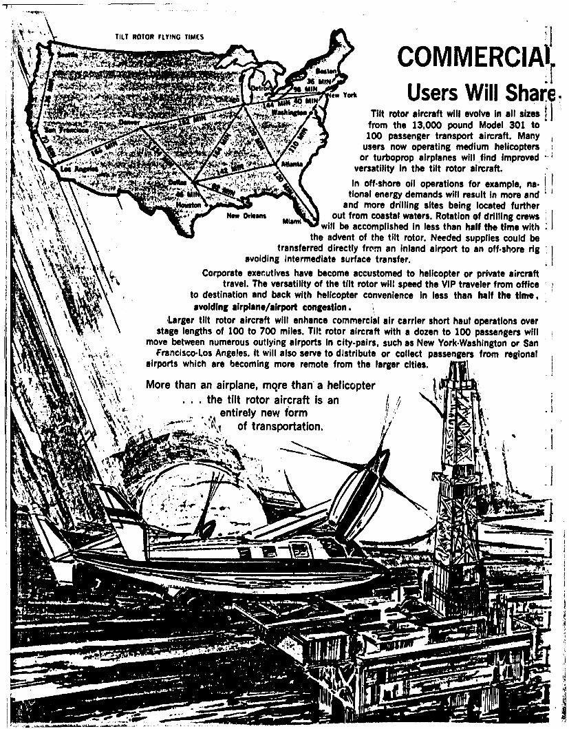
TILT ROTOR FLYING TIMESooY~s coMMERCA,).,", Users Will Share
":l.ashIh. Tilt rotor aircraft will evolve in all sizes
R -from the 13,000 pound Model 301 to,-. ,..-. 100 passenger transport aircraft. Many
or now operating medium helicopters'.i:' or turboprop airplanes will find Improved
t4 3- 7 versatility in the tilt rotor aircraft.In off.shore oil operations for example, na. I
tional energy demands will result in more andand more drilling sites being located further
Now Or an out from coastal waters. Rotation of drilling crewswill be accomplished in less than half the time with
the advent of the tilt rotor. Needed supplies could betransferred directly from an inland airport to an off.shore rig
avoiding intermediate surface transfer.Corporate executives have become accustomed to helicopter or private aircraft
travel. The versatility of the tilt rotor will speed the VIP traveler from officeto destination and back with helicopter convenience in less than half the time,avoiding airplane/airport congestion.
Larger tilt rotor aircraft will enhance commercial air carrier short haul operations overstage lengths of 100 to 700 miles. Till rotor aircraft with a dozen to 100 passengers will
move between numerous outlying airports in city-pairs, such as New York.Washington or SanFranciscoLos Angeles. It will also serve to distribute or collect passengers from regional
airports which are becoming more remote from the larger cities.
More than an airplane, more than'a helicopter. . . the tilt rotor aircraft is an I
entirely new form ..of transportation. t -'
_..1
............
'I
..
;-- eo• "
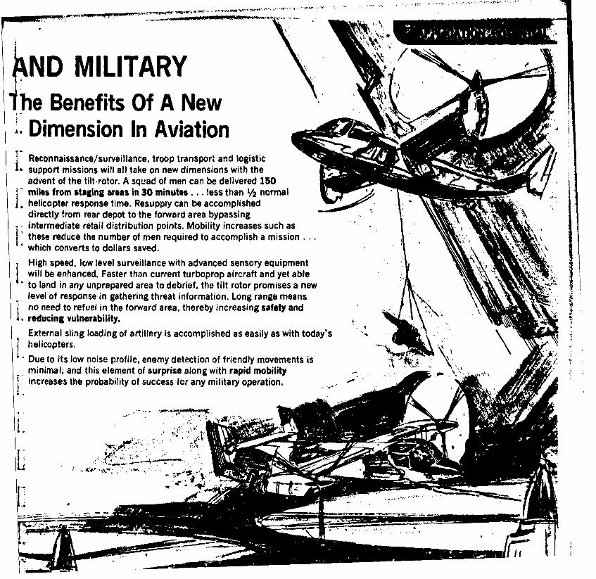
ND MILITARYihe Benefits Of A New
Dimension In AviationReconnaissance/surveillance, troop transpor, and logistic
I- support missions will all take on new dimensions with theadvent of the tilt-rotor. A squad of men can be delivered 150miles from staging areas in 30 minutes... less than 1/2 normalhelicopter response time. Resupply can be accomplisheddirectly from rear depot to the forward area bypassingintermediate retail distribution points. Mobility increases such asthese reduce the number of men required to accomplish a mission.which converts to dollars saved,High speed, low level surveillance with advanced sensory equipmentIwill be enhanced, Faster than current turboprop aircraft and yet ableto land in any unprepared area to debrief, the tilt rotor promises a newlevel of response in gathering threat information. Long range meansno need to refuel in the forward area, thereby increasing safety and
• reducing vulnerability.External sling loading of artillery is accomplished as easily as with today'sI helicopters.
Due to its low noise profile, enemy detection of friendly movements isminimal; and this element of surprise along with rapid mobility "increases the probability of success for any military operation.

...mostTransport - Rescue - Reconaissance Attack
I - VERSATILESurveillance - Resupply - Utility - Command And Control• Any Helicopter Mission Can Be Effectively Performed AIRCRAFTBy The Tilt Rotor Aircraft.
Of The Future
As a high speed rescue aircraft, the tilt rotor can reach a downedairman two to three times as fast as present systems.Good loiter/hover characteristics aid in location. Low downwashfacilitates the rescue. Even more important, the tilt rotorcan return smoothly to medical facilities at over 300knots while medical attention is given enroute.
I ,I"
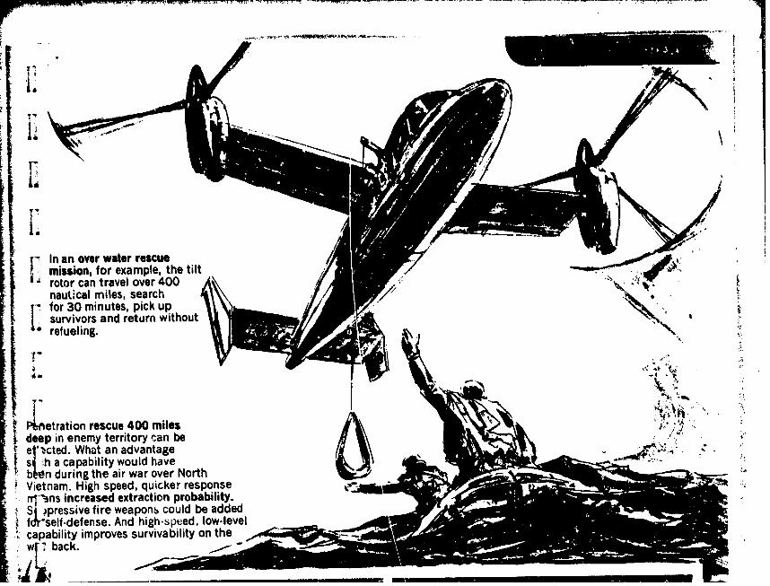
T7
rotor can travel over 400
refueling.
i~erto recu 400 milesdeinenemy territory can beshacapability would haveIn dringthe air war over NorthVietam. ighspeed, quicker response
iprsi finree extraction probability.fdself -defense. And high-speed, low-level
Scapability improves survivability on the,W back.
Bel
HEIOPE
f -T M C Y 1 7
_______ d Asmepuc -1 1IDivision of Textron Inc
I:
I. APPENDIX E
j CURRENT UNITED STATES COAST GUAKDPROGRAM OBJECTIVES AND DESCRIPTIONS*
I:[
Iii
*Includes excerpts from The U.S. Coast Guard: Its Msaions and objeotiveo,U.S. GPO, 1977.
Dvimon of Tex lon Inc
E-1. INTRODUCTION
The, following sections detail the USC, programs and objectives listed below:
a. ENFORCEMENT OF LAWS AND TREATIES (ELT)
b. MARINE ENVIRONMENTAL PROTECTION (MEP)
c. MILITARY OPERATIONS/PREPARED (MO/MP)Ij d. PORT SAFETY AND SECURITY (PSS)
e. SEARCH AND RESCUE (SAR)
I f. SHORT-RANGE AIDS TO NAVIGATION (A/N)
g. MARINE SCIENCE ACTIVITIES (MSA)
h. ICE OPERATIONS (10).
E-2. ENFORCEMENT OF LAWS AND TREATIES
SOBJECTIVEThe objective of the ELT program is to enforce all federal laws in the. marine
Ienvironment, except those specifically assigned to other Coast Guard programs(ie, vessel safety, marine pollution, vessel traffic control, and port safetyand security). In recent years ELT enforcement efforts have focused par-ticularly on laws relating to fisheries protection, immigration, and drugsmuggling.
PROGRAM DESCRIPTION
ELT can claim to be the oldest Coast Guard program since the Revenue Marine,the ancestor of the modern Coast Guard, was established in 1790 to suppresssmuggling. Today, as the federal maritime enfornement agency, the Coast Guardis responsible for enforcing all federal laws an the navigable water of theUnited States and its possession~s, and on the high seas. The laws to beenforced fall into two categories: laws relating to marine safety for whichthe Coast Guard has sole responsibility; and laws relating to customs andrevenue, immigration, quarantine, neutrality, protection of fish and game,marine environmental protection, and other matters that fall within thejurisdiction of other federal agencies for which the Coast Guard sharesenforcement responsibility, and the unique facilities of the Coast Guard arrequired to accomplish maritime law enforcement.
E-1
- 5 ' ' ~ '-': :
Dv__on of extron ;ic.
The ELT program encompasses a wide variety of duties covering a broad geo-graphic area; included are the enforcing of laws and regulations governingthe fishery conservation zone extending 200 nautical miles off the U.S. coasts;interdicting drug and alien smuggling in areas such as the Caribbean; ensuringthat U.S. tuna boats off the shores of South America comply with the inter-American Tropical Tuna Convention; and minimizing of damage and loss of fishinggear caused by conflicting deployment of mobile and fixed equipment, such asthe simultaneous use of lobster pots and bottom trawls off the New Englandcoast.
The functional elements of an enforcement system are detection, surveillance,and apprehension.
I'E-3. MARINE ENVIRONMENTAL PROTECTION PROGRAM
[ OBJECTIVE
The primary objective of the MEP program is to maintain or improve the qualityof the marine environment through preventive measures. The secondary objec-tive is to minimize the damage caused by pollutants discharged into the marineenvironment by providing coordinated and effective response to remove dischargesof oil or hazardous substances.
I. PROGRAM DESCRIPTION
Congress has established the restoration and maintenance of the chemical,. physical, and biological integrity of the waters of the nation as a national
objective. The Coast Guard is the primary maritime agency empowered to meetthis national objective.
The role for the Coast Guard in marine environmental protection is a logicalextension of its traditional missions in marine and port safety, and law
17 enforcement.
The MEP program is divided into six major operational components, namely,response, enforcement, prevention, monitoring and surveillance, impact assess-ment, and in-house abatement.
Initial efforts were designed to solve the immediate problem of minimizingthe effc--ts of pollution. More recent actions have concentrated on developingan adequate cleanup (response) capability to effectively remove most oil dis-charges. Current efforts in this area are concentrating on special technicalproblems for oil removal, removal of hazardous substances, and the removal ofpollutants in the arctic environment.
In addition to attempting to resolve the immediate problems of cleanup, asecond phase has been initiated to eliminate all types of discharges. Effortsare being directed at establishing an effective enforcement program, coupled
E-2
--- - -

-_ _ _ __ __ d Aropece -Ovldon of Textron Inc.
with public awareness and education campaigns. Future efforts in this areawill attempt to improve the level of enforcement in the coastal areas and toprovide limited coverage in those outlying areas where little or no enforce-ment activity is presently conducted.
The U.S. Coast Guard Pollution Prevention Regulations for " sels and oil trans-fer facilities, which went into effect on 1 July 1974, sig .,ed the beginningof the third phase of the program, prevention. Additional regulations, suchas those dealing with hazardous substances, will be developed as necessary inconjunction with public education efforts, in a unified enforcement approach.
Several other initiatives support the response, enforcement, and preventionphases of the MEP program. Monitoring and surveillance serve to meet programobjectives in two ways; first, adequate detiction enhances enforcement capa-bilities as well as being a deterrent which aids in preventing discharges;second, this activity provides the Coast Guard with an impact assessment capa-bility which can be ubed to judge the damage or the impact of pollutants onthe marine environment. This information is required to ensure effectivecleanup and to establis% effective prevention policies. Initial steps toaccomplish this are taken by providing surface and air surveillance in coastaland port areas.
To complement thc aircraft, cutters, and boats that conduct the bulk of theMEP program, three major items of response or cleanup equipment are in use.These are the Air-Deliverable Antipollution Transfer System, a high-seas oil-containment device, and t,:o types of oil recovery devices.
E-4. MILITARY OPERATIONS/PREPAREDNESS PROGRAM
OBJECTIVE
The objective of the HO/NP program is to maintain the Coast Guard as aneffective and ready armed force prepared for, and immediately responsive-to, assigned tasks in time of peace, war, or national emergency. Thisincludes readiness to function as a specialized service in the Navy in timeof war, responding to national disasters and domestic emergencies, and theefficient conduct of peacetime missions. The program unifies both prepared-ness and operations.
PROGRAM DESCRIPTION
The comand and control system, and the operational trairing provided by MO/HPare essential to respond rapidly and effectively under all conditions.
In order to maintain the Coast Guard as an effective and ready armed force,MO/MP combines training with the preparation of contingency plans based onrealistic assessments of Coast Guard capabilities.
E-3
- - -- ,---- ....- ------ , ---

Ovision of Textron Inc.
Personnel readiness is achieved for both peacetime and wartime tasks throughon-the-job training, augmentation training, specialized training exercises,and formal clasaroom instruction. Training standards and programs are basedon Coast Guard routine and contingency responsibilities. Joint command postaud joint operational, multi-unit, and individual exercies, are scheduledperiodically to promote military preparedness. The Coast Guard participatesin the DOD Worldwide Military Command and Control System. Participation infleet and interservice exercises is geared to ensure that personnel and mate-rial performance are to Navy standards. Personnel contingency requirementsto be met by reserve personnel are established in conjunction with the ReserveForces Program. Reserves constitute a very valuable and essential element ofthe overall Coast Guard military capability.
Material readiness consists of equipping and maintaining Coast Guard operatingfacilities and personnel with combat gear necessary to maintain a state ofreadiness to perform its combat, combat support, and peacetime duties, suchas law enforcement. The goal is to ensure the operating forces are outfittedand equipped as required for full-mission performance.
Typical tasks which may be requireO of the Coast Guard in wartime are surveil-lance for enemy forces, antisubmarine warfare (AWS), protection of offshoreinstallations, convoy escort, and logistics supply.
E-S. PORT SAFETY AND SECURITY PROGRAM
OBJECTIVE
The objective of the PSS program is to safeguard the navigable waters of thenation and adjacent shore areas, including ports and their related facilities,from accidental or intentional harm. By assuring the safety of the ports andwaterways, vital transportation links are facilitated.
PROGRAM DESCRIPTION
The Ports and Waterways Safety Act (PWSA) of 1972 was written to prevent damageto, or destruction or loss of any vessel, bridge, or other structure on, in,or near the navigable waters of the U.S., and to protect the navigable watersand the resources therein from environmental harm resulting from vessel orstructure damage.
PSS is administered by the Coast Guard Captains of the Port (COTPs). Theprogram is complex and interfaces with several other program areas.
E-4
8d P am TVDOmMon of Textron Inc
L Currently, there are over SO Captains of the Port with approximately 1600 field
billets designated for PSS and MEP duties. These functions include monitoringand supervision of oil transfer and hazardous cargo operations, cleaning uppollution, conducting harbor patrols, inspecting and surveying waterfrontfacilities, establishing safety and security zones as required, and controllingmovements and anchorages.
The activities of the PSS program are many and varied, but can be categorizedinto the following major areas:
a. Prevent intentional or accidental mishandling of cargo in U.S. portsand waterways
L b. Prevent threats and acts of espionage, sabotage, and intelligence
gathering
c. Reduce the likelihood of fires and explosions in the port areas
d. Reduce the probability of ship collisions or groundings
e. Assist vessels to transit U.S. ports safely and economically in aminimum of time
f. Promote unified and consolidated rules of the nautical road inaccordance with international regulations for preventing collisions at sea
g. Enhance cargo security within the entire marine terminal complex.
Vessel traffic management is an important means of ensuring safe operation incertain ports and waterways. This function is provided by Coast Guard Vessel1! Traffic Services (VTS) using the following procedures. Using a VHF/FM com-munication network, and in most cases some form of electronic surveillance,information on vessel positions and movements is collec.ted by a shore-basedvessel-traffic certer. After analyzing the data, VTS provides accurate andcomprehensive information to vessels on the status of other vessels and otherrelevant navigation information. In addition, congestion or other conflict
j2 situations are predicted as far in advance as possible. Vessels are alertedto such potential problems so that corrective measures can be taken.
E-6. SEARCH AND RESCUE PROGRAM
OBJECTIVE
The objective of the SAR program is to minimize loss of life, injury, andproperty damage by rendering aid to persons and property in distress in themarine environment, including the inland navigable waters.
E-S
Divtsn of Textron Inc
PROGRAM DESCRIPTION
Search and rescue is the mission most readily identified with the Coast Guard.This mission is one of the earliest and most traditional functions of the CoastGuard, and continues to demand the highest priority in all aspects of CoastGuard operations. The origins are twofold: the Revenue Marine was tasked bythe Secretary of the Treasury in the early 19th century to render assistanceto vessels in distress in the course of conducting its antismuggling patrols;within the same general time frame, the U.S. Lifesaving Service was establishedto provide a network of beach patrols which launched surf boats to rescue crewsfrom distressed ships. In 1915 these two services were combined as elements ofthe Coast Guard.
Economic and technological advances have changed the search and rescue clien-tele. The rapid expansion of recreational boating, the increase of poweredfishing vessels, and the accepted responsibility of the United States to providea greater degree of assistance to the mariner on the high seas, has created newdemands for providing search and rescue capability. The Coast Guard has respondedto these demands by evolving search and rescue systems encompassing stations,ships, aircraft, and boats linked by modern communications networks, and cen-trally controlled and directed by rescue coordination centers.
The current national SAR plan has established three SAR regions; inland, mari-time, and overseas. The Coast Guard is the designated coordinator for themaritime region. SAR facilities have been established at numerous points alongthe East, West, and Gulf Coasts, and in Alaska, Hawaii, American Samoa, andPuerto Rico.
Although the maritime SAR region reaches deep into the Atlantic and Pacific,and embraces all of the Gulf of Mexico, it should be noted that 92 percent ofall SAR incidents occur within 25 Miles of the U.S. coastline.
The Automated Mutual-Assistance Vessel Rescue (AMVER) system, operated by theCoast Guard, is an international program designed to assist the safety of mer-chant vessels on the high seas. Merchant vessels of all nations on offshorepassages throughout the world are encouraged to send sailing plans upon depar-ture from port, and periodic position reports enroute to cooperating radiostations. These reports are forwarded to the AMVER Center located on GovernorsIsland in New York Harbor. There, the information is entered into a computerwhich calculates positions by dead reckoning for the ships throughout theirvoyages, based upon most recent information. When a recognized rescue centerof any nation learns of an emergency at sea, it may obtain a computer-predictedlisting of ships in the vicinity of the emergency to determine which, if any,might be well suited to provide help. Valuable search and rescue data, suchas the radio watch schedule of each ship and whether she carries a doctor, is
E-6

rJ
vi.
_ _ __ _ __ _ Ad e pace D 11Division of Textron Inc.
kept on file in the computer and is also printed for each ship listed. Thelocation of a participating individual vessel may also be obtained by rescueauthorities if her safety is in question. Predicted vessel locations aredisclosed only for reasons related to maritime safety. This system has provedto be an extremely cost-effective means of providing mid-ocean SAR.
SE-7. SHORT-RANGE AIDS TO NAVIGATION PROGRAM
OBJECTIVE
The objective of the A/N program is to assist the mariner in determining his
position and to warn him of dangers and obstructions so that he may follow asafe course. This is accomplished by providing navigational rtferences suchas audio, visual, or electronic signals, and using buoys and lights.
PROGRAM DESCRIPTIONLIn order to understand the application and impact of th) short-range aids tonavigation program it is useful to have historical Perspective of the evolu-tion of the program. The A/N program has a broad geographical scope in thataids to navigation cre established and mairtained in or near U.S. navigablewaters, territories and possessions of the United States, the Trust Territoryof the Pacific Islands, and where required to support the Department of Defense.
Effective use of the services provided requires some degree of knowledge bythe user in order to employ the system properly. Users range from the sophis-ticated professional navigator to the relatively untrained and unskilled rec-reational boater. The differing level of these abilities means that the CoastGuard must satisfy a broad spectrum of user needs.
* Of the roughly 78,000 short-range aids to navigation in use, neaTly 60 percentare aids for which the Coast Guard is wholly responsible. The remainder areprivately owned aids for which the Coast Guard has a management responsibility.
The popularly held image of the traditional A/N program, exemplified by mannedlighthouses and "Bes-Ohh" sound signals, is not completely accurate today sincethe current operations of the program incorporate many modern technologicaladvances. For example, transistorized flashers and photocell daylight controlsare standard equipment on minor aids to navigation. Similarly, automation andremote monitoring of lighthouses have reduced operating costs considerably,and have released many Coast Guard personnel for other duty. A major effortto replace lightships with less expensive and more effective offshore towersand large navigational buoys has left only two lightship stations in existence.
In summary, the main areas of Coast Guard involvement are the monitor, repair,and replacement of buoys.
E-7
Diion of Textron Inc.
LE-8. MARINE SCIENCE ACTIVITIES PROGRAM
L OBJECTIVE
The objectives of the MSA program are to provide marine science support to all
Coast Guard programs and to support national economic, scientific, defense,
and social needs.
The specific objectivces of the MSA program are to conduct the internationalice patrol, provide oceanographic services for the support of the SAR, MEP,10, and other Coast Guard programs and to cooperate with and provide assis-tance to other government and scientific organizations in support of national
L marine science objectives.
PROGRAM DESCRIPTION
The Coast Guard marine science effort emphasizes applied oceanography in sup-port of Coast Guard programs and missions. Coast Guard activities in SAR,MEP, and 10 rely heavily on the oceanographic and meteorclogical informationobtained through MSA operations.
The Coast Guard has the greatest federal presence in the coastal zone, andhas the sole U.S. capability for surface transit of ice-covered waters.
In fulfilling its MSA resronsibilities, the Coast Guard cooperates with othergovernment agencies to ensure the efficient use of public resources and thefurtherance of national interests in the marine environment.
The Coast Guard has a long history of cooperation with the National Oceanic
L and Atmospheric Administration (NOAA) through projects with the NationailWeather Service (NS), National Marine fisheries Service (NFS), and Natio1aal
-Ocean Survey (NOS). Additionally, mutual interests have stimulated exchanges
L of services between the Coast Guard and the Department of Defense.
The following brief summary highlights some of the most significant activities[ Icarried Out by the Coast Guard through NSA:a. International Ice Patrol. Commenced in 1914 after the sinking of
the Titanio, now conducted under international agreement. Aircraft and shipsare deployed each year from February to August to detect icebergs near theNorth Atlantic shipping lanes, and to study ice and current conditions.
b. Oceanographic Services. Applied oceanography to support Coast Guaro
Voperations. Sea surface current st:Ldies are conducted to assist in computer
SAR plannin;g. Computerized models of sea currents for the entire U.S. coastineare being developed. In addition to SAR operations, these mdels have applica-tion in pollutant drift prediction and the planning of deep-water ports. Other
E-8
i.
i Division of Textron Inc.
coastal projects being conducted include estuarine pollution studies, timej dependent current modeling, and bays and sounds modeling.
C. Data Buoy Project. This project is administered by NOAA with theCoast Guard providing operational support for deployment and servicing ofbuoys, a technical staff, and a communications system to relay buoy data.An extensive network of buoys provides marine environmental data over thecoastal U.S. from the Gulf of Maine to the Gulf of Alaska, and the Great Lakes.
1. d. Marine and Coastal Weather Observation and Reporting. This projectis conducted as a cooperative effort with the NWS and the Naval Weather ServiceCommand for use in preparation of marine weather forecasts. Approximately 170shore stations and SO cutters report weather data several times daily, NWS-prepared weather forecasts are broadcast to local marine users over Coast
i" Guard communications facilities.
e. Cooperative Projects. The Coast Guard engages in cooperative pro-jects with various federal agencies, and provides marine science expertiseand resources to further national gjals in open-ocean and coastal programs.Many of these projects represent unique efforts, where the Coast Guard con-tributes most or all of the data and services.
j (1) Airborne Radiation Thermometer Surveys. Charts of sea-surfacetemperatures in continental-shelf regions are compiled from
V data acquired monthly by Coast Guard aircraft using infraredradiation thermometers. These charts of both the East and Westcoasts are provided to U.S. Government agencies and the civil-ian 8: itime comuity for use in search and rescue, marine
1environmental protection, and fisheries-related problems.(2) Ocean Sounding Program. Bathymetric data is routinely supplied
to the Defense Mapping Agency Hydrographic Office by cuttersengaged in regular Coast Guard functions. This data becomesan input to charts used by all members of the maritime community.
(3) IGOSS Marine Pollution Monitoring Pilot Project (MAROPP). High-endurance cutters conduct tarball sampling on a regular basis.Tarballs are lumps of floating petroleum residue of both naturaland human-induced origins. The monitoring of ocean surfacetar is useful in evaluating the effectivtness of oil controlmeasures and the d~spersion of marine pollutants.
E-9
- .-.[- - .~.~.
, . _ _ _ _ _ _ _ _ _ __, .......... ..
I; Dvision of Textron Inc.p
E-9. ICE OPERATIONS PROGRAM
j d' OBJECTIVE
( The objective of the 10 program is to facilitate maritime transportation4 fand other activities in the national interest in ice-laden domestic andIpolar waters. The services provided in the 10 program also assist in
ice environment.
PROGRAM DESCRIPTION
I In 1936, a presidential executive order established national policy on use ofvessels for icobreaking operations in channels and harbors. The Coast Guardwas directed to keep channels and harbors open for the reasonable demands ofcommerce insofar as practicable by performing icebreaking operations. Inaresponse to a determination that the national interest would best be servedby concentrating all icebreaking resources in one agency, the U.S. Navy trans-
* [ ferred its icebreakers to the Coast Guard in 1965.
Icebreaking services are provided for three major purposes:
j a. To assist in the safe and timely movement of maritime traffic
b. To prevent and control flooding resulting from ice accumulation on[ domestic waterways
c. To support scientific research and other national interests in thepolar regions.
Because of the differences between the geographic areas in which these activi-ties are conducted, the 10 program can be best understood by considering polarand domestic operations separateiy.
POLAR OPERATIONS
1. In the polar regions, icebreakers escort resupply ships into ice-laden areas,carry fuel and cargo to -isolated U.S. installations, survey uncharted waters,collect meteorological and oceanographic data, and serve as platforms to carry
1 "research scientists into remote and otherwise unreachable areas.
The polar icebraaking fleet currently consists of one GZaoier-class vessel,built in 1955, three smaller and older hWnd-class vessels (two of which havebeen reengined to extend their service lives) and two new Potcw-class ice-breakers. Throe other Wnd-class icebreakers were decommissioned in recentyears as constriction of the PoZa' class wss nearing completion, and an addi-tional knd is scheduled for decommissioning in 1978.
I-1O
_ _ _ _ _ __ _ _ _ OW Auraipm01voon of Textron Inc
LThe replacement of the Wind-class vessels by the two PoZar-class icebreakerswill decrease the total number of available icebreaking days. This deficitJ may be partially overcome by increasing the operation of the PoZa class by33 percent over previous icebreakers. This increase would exceed rdrsonelconstraints for time away from home port, and will require the 'se of amultiple-crewing concept similar to that used on Navy nuclear submarines. Asplanned, the ashore crew, together with a small permanent staff, would com-prise the Icebreaker Support Facility located in Seattle, Washington (thePoar-class home port). They would be tasked with coordination of crew train-ing and maintenance for the Polar-class icebreakers.
DOMESTIC OPERATIONS
One of the most important responsibilities of the Coast Guard is to keep opento shipping domestic traffic routes and ports that are normally utilized year-round. The 10 program also attempts to extend navigation seasons in ice-ladenIi areas when such extensions are considered in the national interest. Forexample, the Coast Guard has been one of the major participants in the multi-agency Great Lakes season extension project. The Coast Guard also cooperateswith other agencies to prevent and control flooding caused by ice jams. Per-formance of these duties requires icebreaking services as well as the collec-tion and dissemination of information (mapping).
I. The United States domestic icebreaking ficet currently consists of one dedi-cated icebeeaker (on the Great Lakes) a.ssisted part-time by a Wind-class polaricebreaker and a multitude of smaller, multipurpose cutters with icebreakingcapabilities.
Aircraft perform surveillance patrols to evaluate ice conditions and recommendship routes through areas having ice formations.
I.
E- 11

L
~i
I APEDIi
!
ii
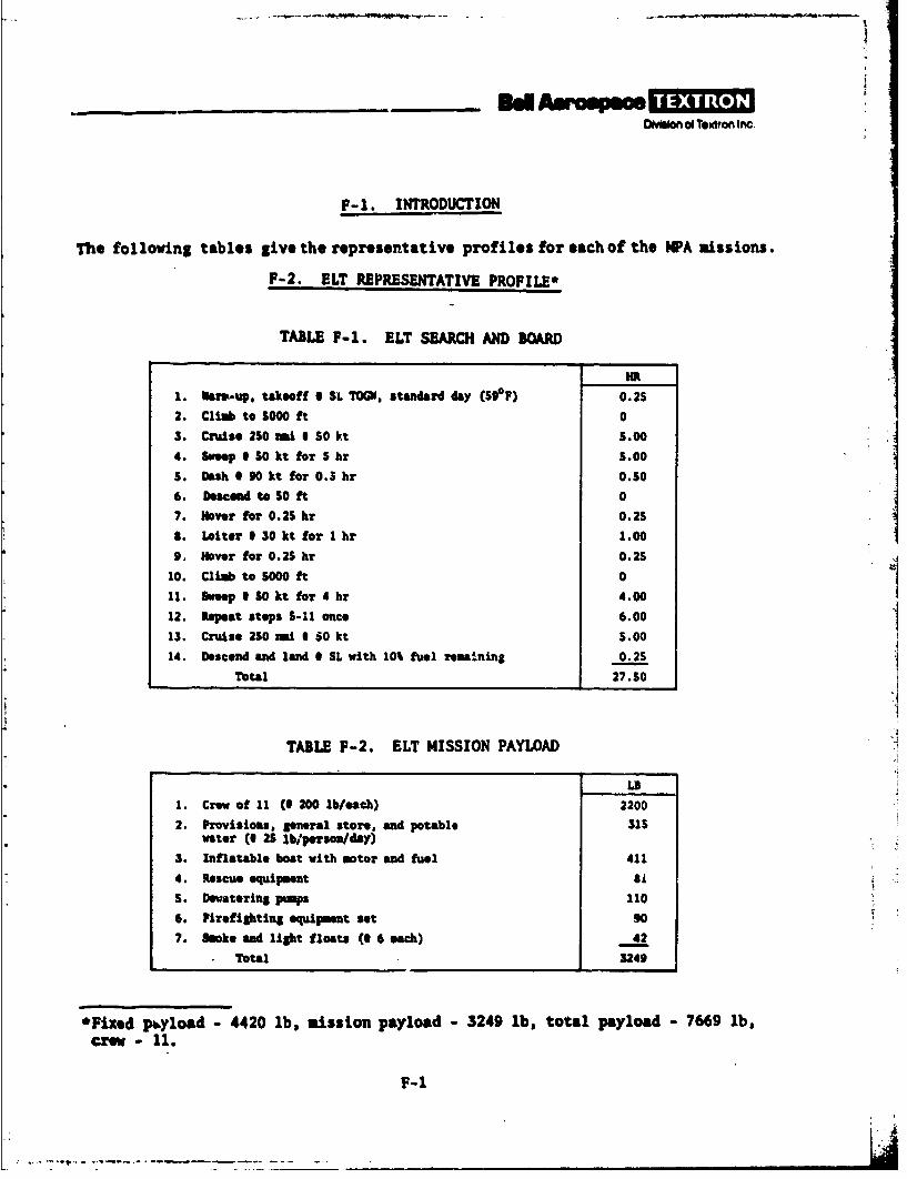
OvIon oi Textron Inc
F-1. INTRODUCTION
The following tables give the representative profiles for each of the lPA missions.
F-2. ELT REPRESENTATIVE PROFILE*
TABLE F-1. ELT SEARCH AND BOAU)
Hit
1. Nar-up, takeoff I SL ro;W. standard day (5S°F) 0.25
2. Climb to 5000 ft 0
3. Cruise 2S0 mi I SO kt 5.004. Sweep I SO kt for 5 hr 5.00
S. Dash 4 90 kt for 0.5 hr 0.50
6. Descnd to 50 ft 0
7. Hover for 0.25 hr O.2S
S. Loiter 1 30 kt for I hr 1.00
9, Nover for 0.25 hr 0.25
10. Climb to 5000 ft 0
11. Smeep I SO kt for 4 hr 4.00
12. Repeat steps 5-11 once 6.00
13. Cruise 2SO mi 1 50 kt S.00
14. Descend and land I SL with 10% fuel remaining 0.2STotal 27.50
TABLE F-2. ELT MISSION PAYLOAD
L9
1. Crew of 11 (0 200 lb/each) 2200
2. Provisions, general store, and potable 315water (0 2S lb/person/day)
3. Inflatable boat with motor and fuel 411
4. Rescue equipment G'
5. Deatering pumps 110
6. Pirefighting equipment set 90
7. Sooke and light floats (1 6 each) 42
Total 3249
*Fixed pbyload - 4420 lb, mission payload - 3249 lb, total payload - 7669 lb,
Crew 11.
1-1
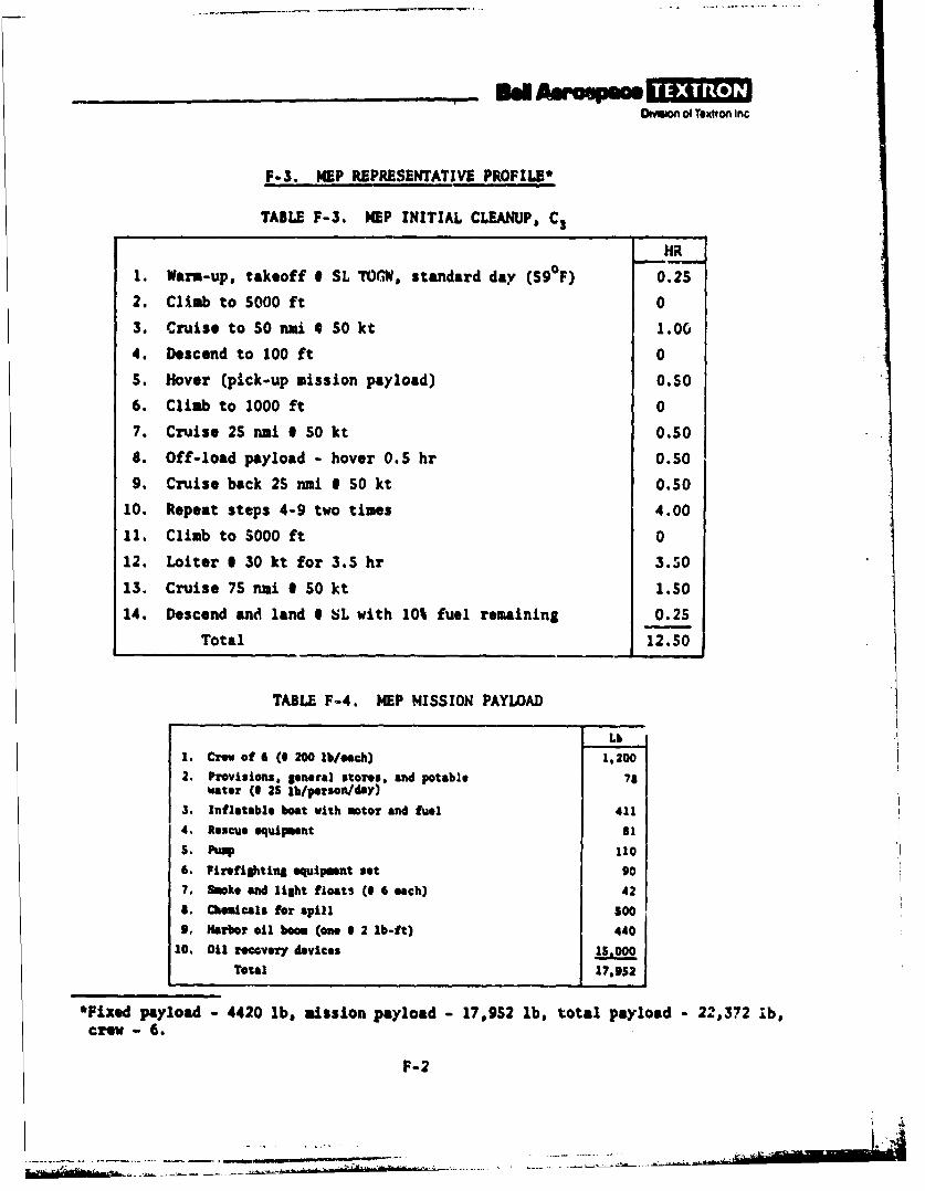
nd, Awp,OMlm Of Textron Inc
F-3. MEP REPRESENTATIVE PROFILE*
TABLE F-3. NEP INITIAL CLEANUP, C3
HR
1. Warm-up, takeoff I SL TOGW, standard day ($90F) 0.25
2. Climb to 5000 ft 0
3. Cruise to 0 mi 50 kt 1.0
4. Descend to 100 ft 0
S. Hover (pick-up mission payload) 0.506. Climb to 1000 ft 0
7. Cruise 25 nami 50 kt 0.50
8. Off-load payload - hover 0.5 hr 0.50
9. Cruise back 25 ni 0 50 kt 0.5010. Repeat steps 4-9 two times 4.00
11. Climb to $000 ft 0
12. Loiter 6 30 kt for 3.5 hr 3.50
13. Cruise 75 nmi 0 50 kt 1.50
14. Descend and land SL with 10% fuel remaining 0.25
Total 12. 50
TABLE F-4. MEP MISSION PAYLAD
Lb1. Crew of 6 ( 200 lb/ach) 1,2002. Provisions, general stores. and potable 78
water (I 25 lb/person/daY)3. Inflatable boat with motor and fuel 4114. Rescue equipment 81S. Pump 1106. Firefighting equipment set 907. soke and light floats (1 6 each) 428. Chemicals for spill S09. Harbor oil boom (one 1 2 lb-ft) 44010. Oil recovery devices 15,000
Total 17,952
*Fixed payload - 4420 lb, mission payload - 17,952 lb, total payload - 22,372 1b,crew - 6.
F-2
~------------------ s
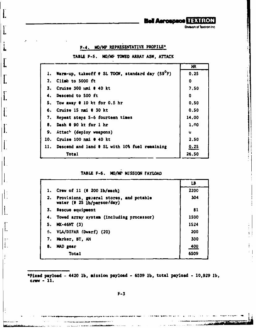
IDMeOn of Texttonl Inc
L F-4. MO/M REPRESENTATIVE PROFILE'
TABLE F-S. MO/JO TOWED ARRAY ASW, ATTACK
- - HR
1. Warm-up, takeoff 0 SL TOG, standard day (59F) 0.25
2. Climb to 5000 ft 0
3. Cruise 300 mi 1 40 kt 7.50
4. Descend to 500 ft 0
5. Tow away 1 10 kt for 0.5 hr 0.50
6. Cruise 15 nai. 30 kt 0.50
7. Repeat steps 5-6 fourteen times 14.00
8. Dash 1 90 kt for 1 hr 1.(09. Attach (deploy weapons) u
10. Cruise 100 nui 640 kt 2.50
11. Descend and land I SL with 10% fuel remaining 0.25
Total 26.50
TABLE F-6. MO/w MISSION rAYLOAD
LB
1. Crew of 11 (0 200 lb/each) 22002. ProvIsions. geiaeral stores, and potable 304
water (125 lb/persol lday)
3. Rescue equipment 812.4. Towed array system (including processor) IS00
S S. NK-46NT (3) 1524
-" 6. VIA/DIFAR (Dwarf) (20) 200
7. Marker, BT, AN 300
.. MADsear 400
Total 6509
*Fixed payload , 4420 lb, mission payload - 6509 lb, total payload - 10,929 lb,crew - 11.
F-3
.. .. ..... -- - -- - . .. - - - - - r - - - - . . . - . .: - -;. :
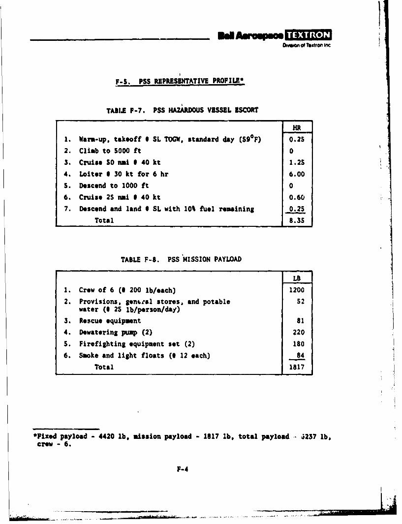
IOIWof Texiton Inc
F-S. PSS RBPRESINTATIVE PROFILE*
TABLE F-7. PSS HAZARDOUS VESSEL ESCORT
HR
1. Warm-up, takeoff I SL TOGW, standard day (S90F) 0.25
2. Climb to S000 ft 0
3. Cruise SO nmi 8 40 kt 1.2S
4. Loiter 1 30 kt for 6 hr 6.00
S. Descend to 1000 ft 0
6. Cruise 2S nmi i 40 kt 0.60
7. Descend and land I SL with 10% fuel remaining 0.2S
Total 8.35
TABLE F-8. PSS MISSION PAYLOAD
LB
1. Crew of 6 (1 200 lb/each) 1200
2. Provisions, genttal stores, and potable 52water (I 2S lb/person/day)
3. Rescue equipment 81
4. Dewatering pump (2) 220
S. Firefighting equipment set (2) 180
6. Smoke and light floats (1 12 each) 84
Total 1817
*Fixed payload - 4420 lb, mission payload - 1817 lb, total payload - 237 lb,crew - 6.
F-4
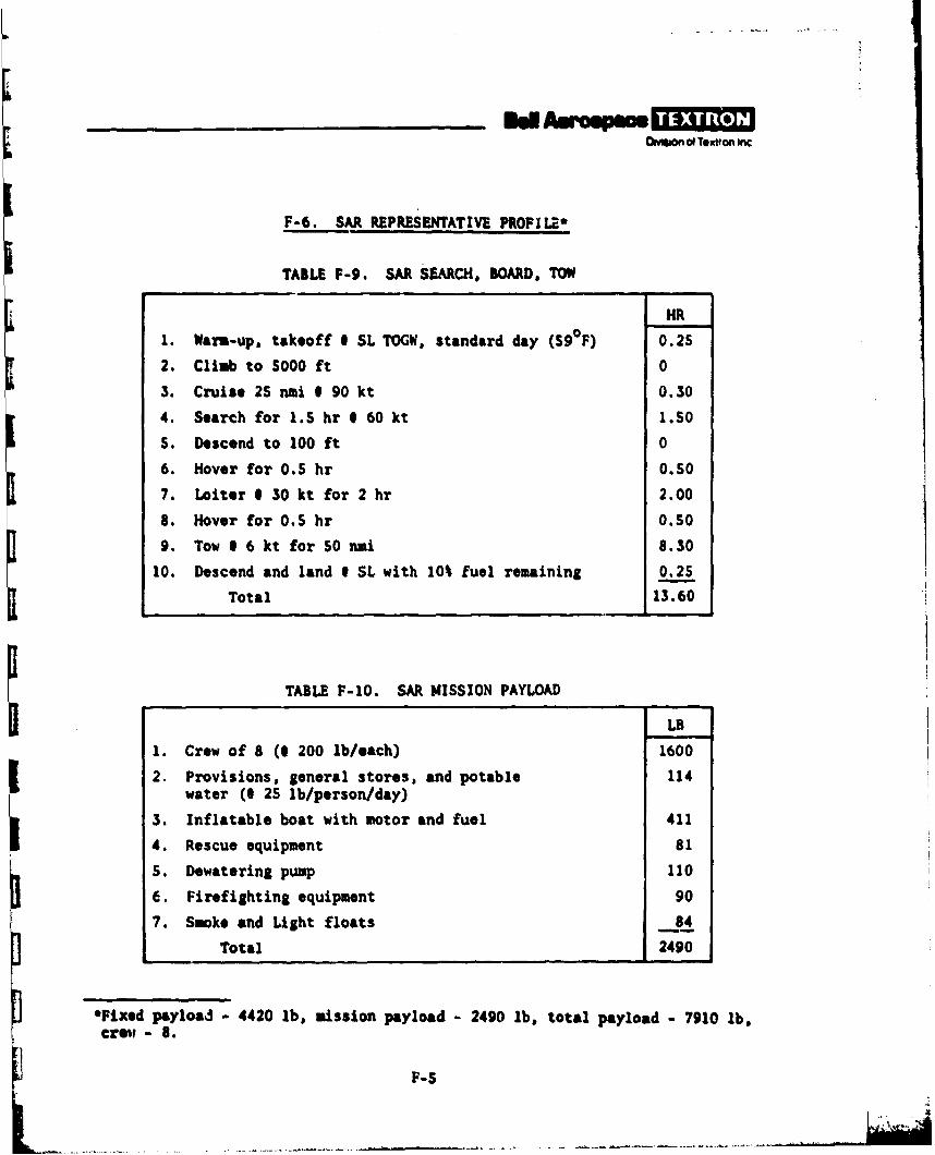
__________Eel-
Oivggon OlToxtto Inc
F-6. SAR REPRESENTATIVE PROFILE*
TABLE F-9. SM SEARCH, BOARD. TOW
HR
1. Warm-up, takeoff 0 SL TOGW, standard day (S90 F) 0.25
2. Climb to S000 ft 0
3. Cruise 2S nmi 1 90 kt 0.30
4. Search for 1.S hr @ 60 kt 1.50
S. Descend to 100 ft 0
6. Hover for 0.5 hr 0.S0
7. Loiter 1 30 kt for 2 hr 2.00
8. Hover for 0.5 hr O.SO
9. Tow 1 6 kt for S0 nmi 8.30
10. Descend and land I SL with 10% fuel remaining 0.25
Total 13.60
TABLE F-1O. SAR MISSION PAYLOAD
LB
1. Crew of 8 (1 200 lb/each) 1600
2. Provisions, general stores, and potable 114water (0 25 lb/person/day)
3. Inflatable boat with motor and fuel 411
4. Rescue equipment 81
S. Dewatering pump 110
6. Firefighting equipment 90
7. Smoke and Light floats 84
Total 2490
*Fixed payload - 4420 lb, mission payload - 2490 lb, total payload - 7910 lb,crew - 8.
F-S
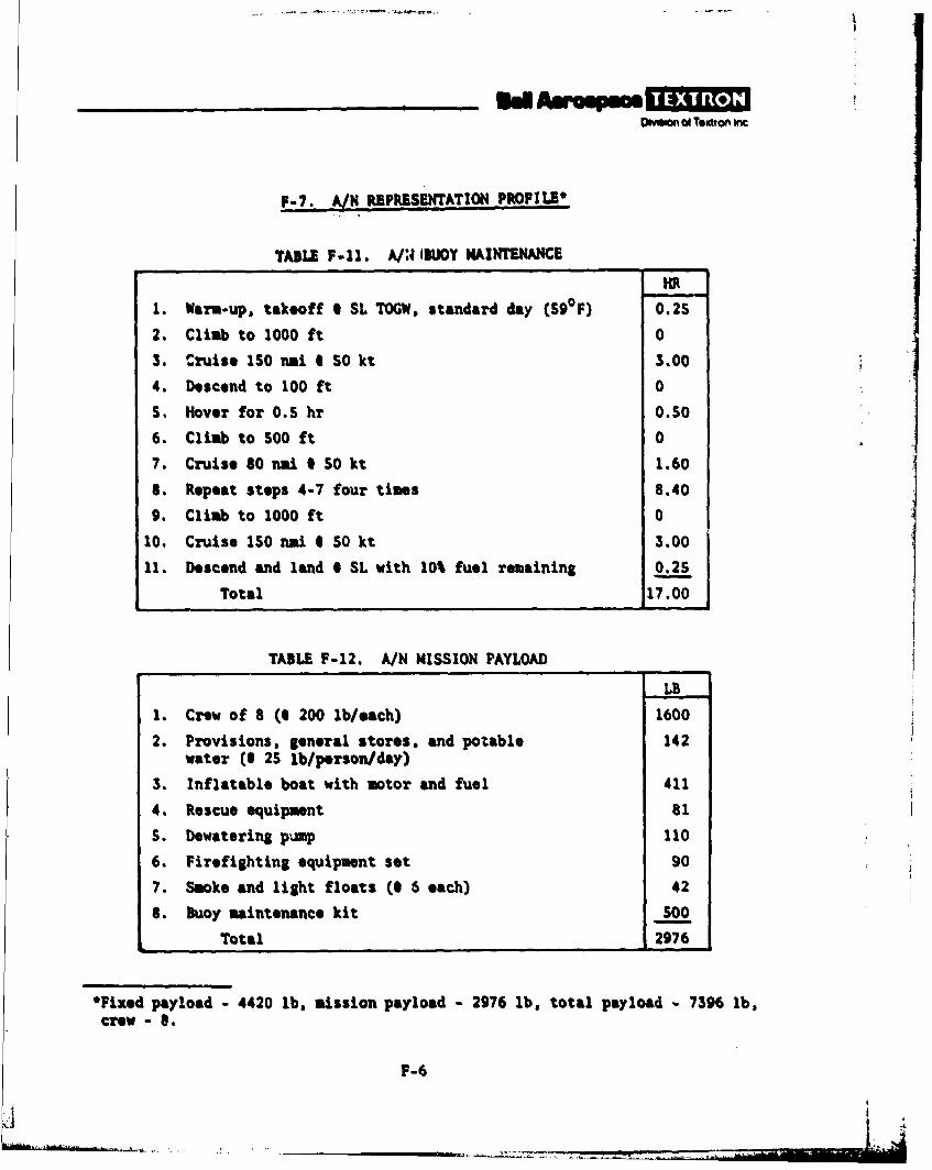
Oae~on 04 Tentrn mnc
F-7. A.. REPRESENTATION PROFILE*
TABLE F-il. A/3 IBUOY MAINTENANCE
HR
1. Warm-up, takeoff I SL TOGW, standard day (590 F) 0.25
2. Climb to 1000 ft 0
3. CWruise ISO i 1 50 kt 3.00
4. Descend to 100 ft 0
5. Hover for 0.5 hr 0.50
6. Climb to 500 ft 0
7. Cruise 80 nmi I SO kt 1.60
S. Repeat steps 4-7 four times 8.40
9. Climb to 1000 ft 0
10. Cruise IS0 nmi I 50 kt 3.00
11. Descend and land I SL with 10% fuel remaining 0.25
Total 17.00
TABLE F-12. A/N MISSION PAYLOAD
LB
1. Crew of 8 (1 200 lb/each) 1600
2. Provisions, general stores, and potable 142water (0 2S lb/person/day)
3. Inflatable boat with motor and fuel 411
4. Rescue equipment 81
S. Dewatering pump 110
6. Firefighting equipment set 90
7. Smoke and light floats (1 6 each) 42
8. Buoy maintenance kit SO0
Total 2976
*Fixed payload - 4420 lb, mission payload - 2976 lb. total payload - 7396 lb,crew - 0.
F-6
1
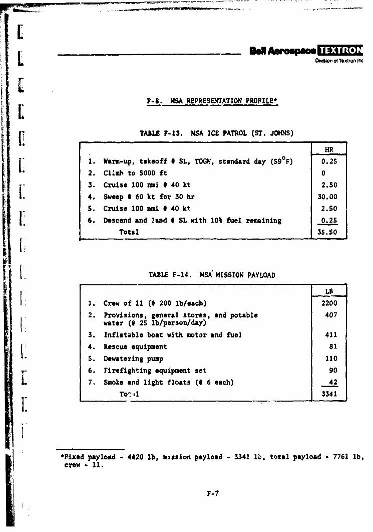
• -Digjon of Textron Inc
L F-8. NSA REPRESENTATION PROFILE*
TABLE F-13. NSA ICE PATROL (ST. JOHNS)
HR
[ 1. Warm-up, takeoff I SL, TOGW, standard day (S90F) 0.25
2. Climb to 5000 ft 0
3. Cruise 100 nm 040 kt 2.50
4. Sweep 1 60 kt for 30 hr 30.00
S. Cruise 100 nmi 1 40 kt 2.50
[ 6. Descend and land 0 SL with 10% fuel remaining 0.25
Total 35.50* i L
r !. TABLE F-14. MSA' MISSION PAYLOAD
LB
1. Crew of 11 (1 200 lb/each) 2200
2. Provisions, general stores, and potable 407water (I 25 lb/person/day)
3. Inflatable boat with motor and fuel 411
k. 4. Rescue equipment 81
5. Dewatering pump 110
6. Firefighting equipment set 90
7. Smoke and light floats (0 6 each) 42
To -1 3341
*Fixed payload - 4420 lb. mission payload - 3341 1b, total payload - 7761 lb,crew-il.
F-7
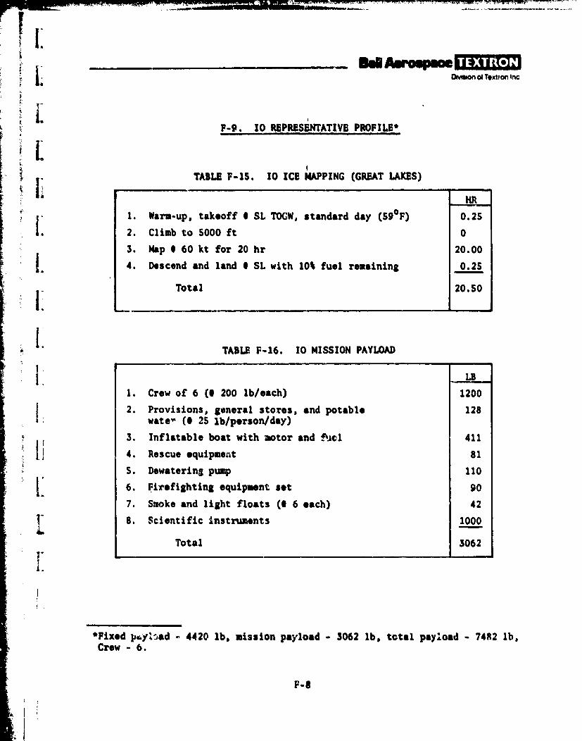
I WoSn of Textron Inc
F-9. 10 REPRESENTATIVE PROFILE*
TABL F-IS. 10 ICE MAPPING (GREAT LAKES)
1. Warm-up, takeoff I SL TOGW, standard day (59°F) 0.25
2. Climb to 5000 ft 0
3. Map 0 60 kt for 20 hr 20.00
j4. Descend and land I SL with 10% fuel remaining 0.25
IiTotal 20.50[-
TABLE F-16. 10 MISSION PAYLOAD
I.-I. LB
1. Crew of 6 (1 200 lb/each) 1200
2. Provisions, general stores, and potable 128I wate- (1 25 lb/person/day)
3. Inflatable boat with motor and 5ucl 411
4. Rescue equipment 81
S. Dewatering pump 110
L 6. Firefighting equipment set 90
7. Smoke and light floats (1 6 each) 42
8. Scientific instruments 1000
Total 3062
*Fixed pyy~sad - 4420 ib, mission payload - 3062 Ib, total payload - 7482 lb,Crew - 6.
F-8
IF
II DM m o of xtrort Inc.
APEDI
SIPIIDMNULAPOC
FO AIIEPTOLARHPDSG
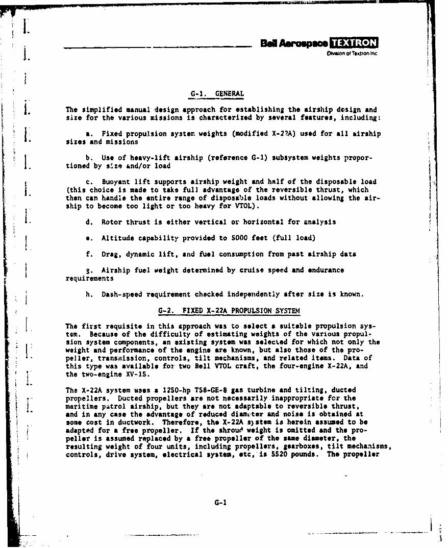
Ovion of Textron Inc
G-1. GENERAL
The simplified manual design approach for establishing the airship dosign andsize for the various missions is characterized by several features, including:
a. Fixed propulsion syste7 weights (modified X-27A) used for all airshipsizes and missions
b. Use of heavy-lift airship (reference G-l) subsystem weights propor-1. tioned by size &nd/or load
c. Buoyant lift supports airship weight and half of the disposable load(this choice is made to take full advantage of the reversible thrust, whichthen can handle the entire range of disposable loads without allowing the air-ship to become too light or too heavy for VTOL).
I. d. Rotor thrust is either vertical or horizontal for analysis
e. Altitude capability provided to SO00 feet (full load)
f. Drag, dynamic lift, and fuel consumption from past airship data
S. Airship fuel weight determined by cruise speed and endurancerequirements
h. Dash-speed requirement checked independently after size is known.
G-2. FIXED X-22A PROPULSION SYSTEM
The first requisite in this approach was to select a suitable propulsion sys-tem. Because of the difficulty of estimating weights of the various propul-sion system components, an existing system was selected for which not only theweight and performance of the engine are known, but also those of the pro-peller, transniission, controls, tilt mechanisms, and related items. Data ofthis type was available for two Bell VTOL craft, the four-engine X-22A, andthe two-engine XV-lS.
The X-22A system %ses a 1250-hp TSa-GE-8 gas turbine and tilting, ductedpropellers. Ducted propellers are not necessarily inappropriate for themaritime patrol airship, but they are not adaptable to reversible thrust,and in any case the advantage of reduced diamcter and noise is obtained atsome cost in ductwork. Therefore, the X-22A s)stem is herein assumed to beadapted for a free propeller. If the shrouO weight is omitted and the pro-peller is assumed replaced by a free propeller of the same diameter, theresulting weight of four units, including propellers, gearboxes, tilt mechanisms,controls, drive system, electrical system, etc,'is S520 pounds. The propeller
G-1
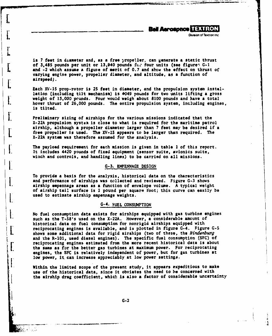
Deo o Txtron n
I"
is 7 feet in diameter and. as a free propeller, can generate a static thrustof 3,485 pounds per unit or 13,940 pounds fei four units (506 figures G-1and -2 which assume a figuie of merit of 0.7 and show the effect on thrust ofvarying engine power, propeller diameter, and altitude, as a function ofairspeed).
Each XV-IS prop-rotor is 25 feet in diameter, and the propulsion system instal-lation (including tilt mechanism) is #049 pounds for two units lifting a grossweight of 13,000 pounds. Four would weigh about 8100 pounds and have a totalhover thrust of 26,000 pounds. The entire propulsion system, including engines,is tilted.
Preliminary sizing of airships for the various missions indicated that theX-22A propulsion systAZ is close to what is required for the maritime patrolairship, although a propeller diameter larger than 7 feet may be desired if afree propeller Is used. The XV-15 appears to be larger than required. TheX-22A system was therefore assumed for the analysis.
The payload requirement for each mission is given in table 1 of this report.It includes 4420 pounds of fixed equipment (sensor suite, avionics suite,winch and controls, and handling lines) to be carried on all missions.
G-3. EMPENNAGE DESIGN
To provide a basis for the analysis, historical data on the characteristicsand performance of airships was collected and reviewed. Figure G-3 showsairship empennage areas as a function of envelope volume. A typical weightof airship tail surface is 1 pound per square foot; this curve can easily beused to estimate airship empennage weights.
G-4. FUEL CONSUMPTION
No fuel consumption data exists for airships equipped with gas turbine enginessuch as the T-SS's used on the X-22A. However, a considerable amount ofhistorical data on fuel consumption for nonrigid airships equipped withreciprocating engines is available, and is plotted in figure G-4. Figure G-5shows some additional data for rigid airships (two of these, the Hindenburgand the R-101, used diesel engines). The specific fuel consumption (SFC) ofreciprocating engines estimated from the more recent historical data is aboutthe same as for the better gas turbines at maximum power. For reciprocatingengines, the SFC is relatively independent of power, but for gas turbines atlow power, it can increase appreciably at low power settings.
Within the limited scope of the present study, it appears expeditious to makeuse of the historical data, since it obviates the need to be concerned withthe airship drag coefficient, which is also a factor of considerable uncertainty
G-2
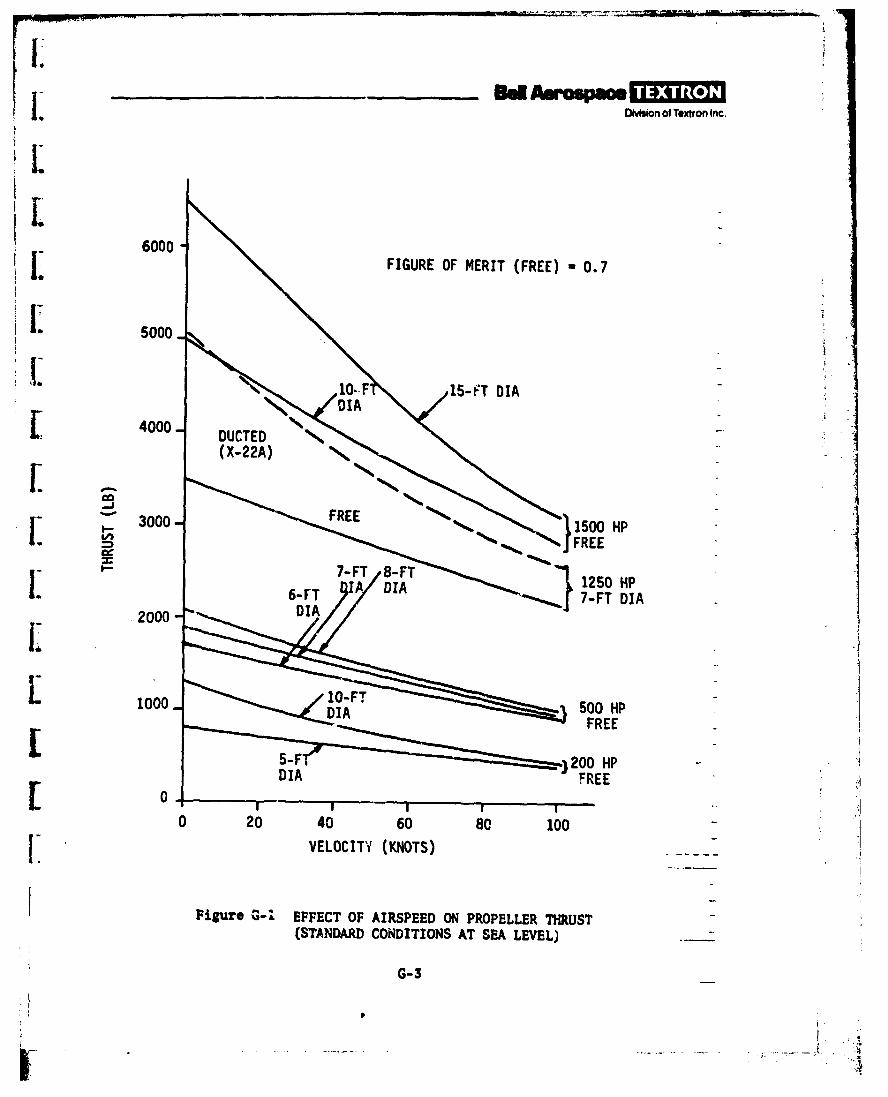
I rI. Dlvaon of Textron Inc,
6000
j. FIGURE OF MERIT (FREE) *0.7
Ii 5000-
[ 4000-
3000-150 HP
6-FT DIA7-FT DIA.2000- I
L1000-D 500 HPFREE
DI FREE0 20 40 60 80 100
L VELOCITY (KNOTS)
1Figuro G-1 EFFECT OF AIRSPEED ON PROPELLER THRUST(STANDARD CONDITIONS AT SEA LEVEL) -
G- 3
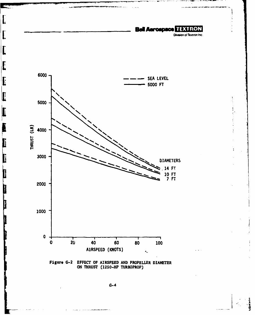
L ODMsio1 of Textron Inc.
6000-L --- SEA LEVEL- 5000 FT
5000
3000
300 DIAMETERS
7 7FT2000
1000
0 20 40 60 80 100
AIRSPEED (KNOTS)
Figure G-2 EFFECT OF AIRSPEED AND PROPELLER DIAMETERON THRUST (1250-HP TURBOPROP)
G-4
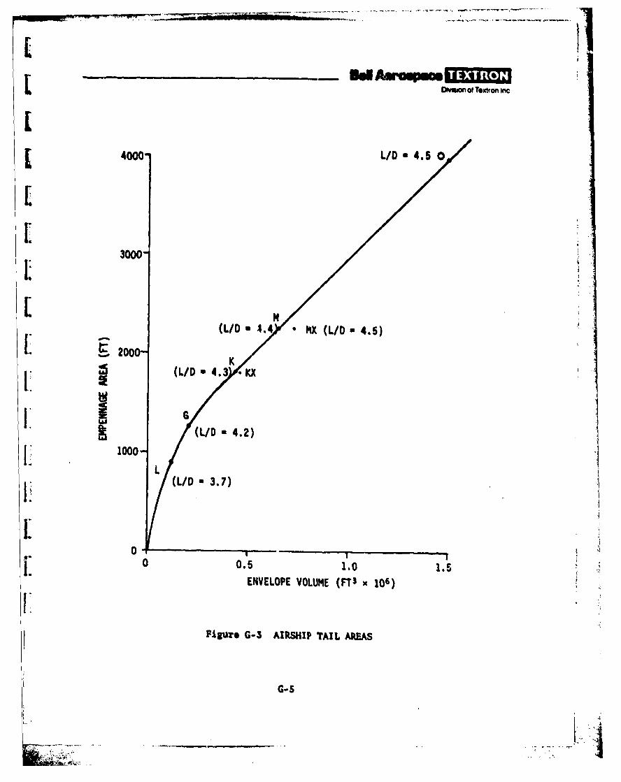
ODmom of Textron inc
[4000 L/D *4.50
3000-
LM[(LID . 4 * iX (LID *4.5)
[ 20(L/D 4.3 K
Ii G(LID -4.2)
LI 1000-
(LID *3.7)
L
0NV0LOP VOLUME (F3 106)
Figure G-3 AIRSHIP TAIL ARtEAS
G- S
W L__________________

•-
Dmson of ToIxton Inc
0XZP-X (REF 6-2)
l0130 KT"j
300, 0 60 KNOTSA 40 KNOTSV3S KNOTS
aI a)c KNlOTS
UPPER MOD AT 60 KNOTS 0 '( Ps-2
TYPICAL AT 50 KNOTS UPPER BOUND AT 40 KNOTS~2O
0 fOR SO KNOTS
/v
SOUNDAT 4
00O. 1.0
VOLUNE, F (FT' 106)
Figure G-4 FUEL CONSLt4PTION OF NEUTRALLY BUOYANT, NONRIGIDAIRSHIPS (RECIPROCATING ENGINES AT SEA LEVEL)
G-6
I
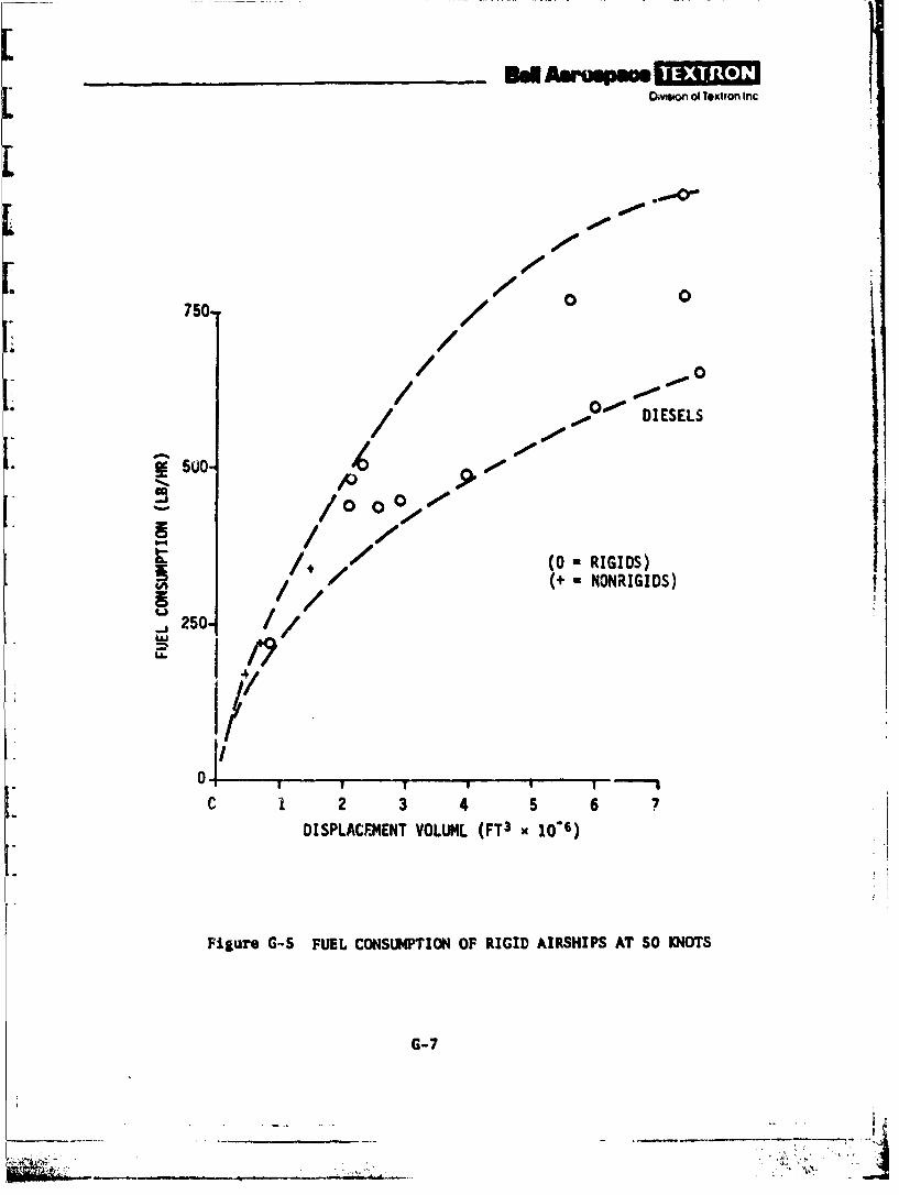
ad. A m i]INvoon of Texton Inc
.000
750 / 0/ 0 0
750. / !/,
0 DIESELS
500
(0 - RIGIDS)C/ (+ NONRIGIDS)
.j2504 1
0
,I/7
C 1 2 3 4 5 6 7DISPLACEMENT VOLUL4L (FT3 x 10-6)
Figure G-S FUEL CONSUMPTION OF RIGID AIRSHIPS AT SO KNOTS
G-7
.. ........ ..-. .MO-vffion of Textron Inc
because of Reynolds number effects. rr -, :Isure G-4, selecting a 1.000,000-ft3airship as a co",,% reference point, a fuel consumption of 250 lb/hr atSO knots seems conservative enough to account for moderate increases in SFC atreduced power with gas turbines. The further possibility exists of shuttingdown one or more of the four engines when power requirements are low, so thatvery high SFCs at low power are largely eliminated. The inclusion of such com-plications in the present limited study does not seem justifiable. Furthermore,the advancement of engine technology should make it possible to bring the higherfuel consumption rate of gas turbines down to the level of reciprocating enginesof 20 or 30 years ago. Therefore, the historical data is used as explainedbelow.
Figure G-6 shows the increase in drag coefficient, C?, with angle of attackfor a ZPG-2 airship, and figure G-7 shows dynamic ift as a function of air-speed and angle of attack. It then becomes possible to construct figure G-8.which relates fuel consumption, angle of attack, envelope volume, and dynamiclift, with the following assumptions:
a. Fuel consumption is proportional to power and time and, therefore,to drag.
b. The fuel consumption for a neutrally bu'yant l,000,000-ft" airshipis 250 lb/hr at SO knots, based on figure G-4. The number also appears reason-able when compared to the propulsion studies conducted for the Navy's AdvancedNaval Vehicle Concept Evaluation (ANVCE) program.
c. Drag is proportional to the volume to the 2/3 power, other thingsbeing equal.
d. Fuel consumption is proportional to power.
e. Dynamic lift for a 1,000,000-ft3 airship at various angles of attackis given by figure G-7.
f. Dynamic lift is proportional to the voume to the 2/3 power, otherthings being equal.
Figure G-8 is the key to the analysis, since the fuel is the predominant designelement. Note that the a a 00 curve does not coincide with zero dynamic liftbecause the airship car makes the craft profile unsymmetrical and because theforward thrust line is below the envelope axis of symmetry.
G-8
- Al
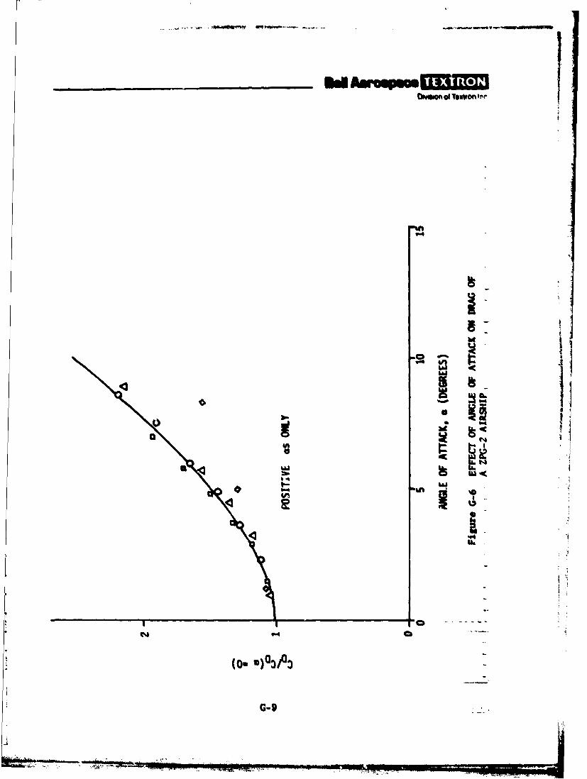
LI -oU
G-9i
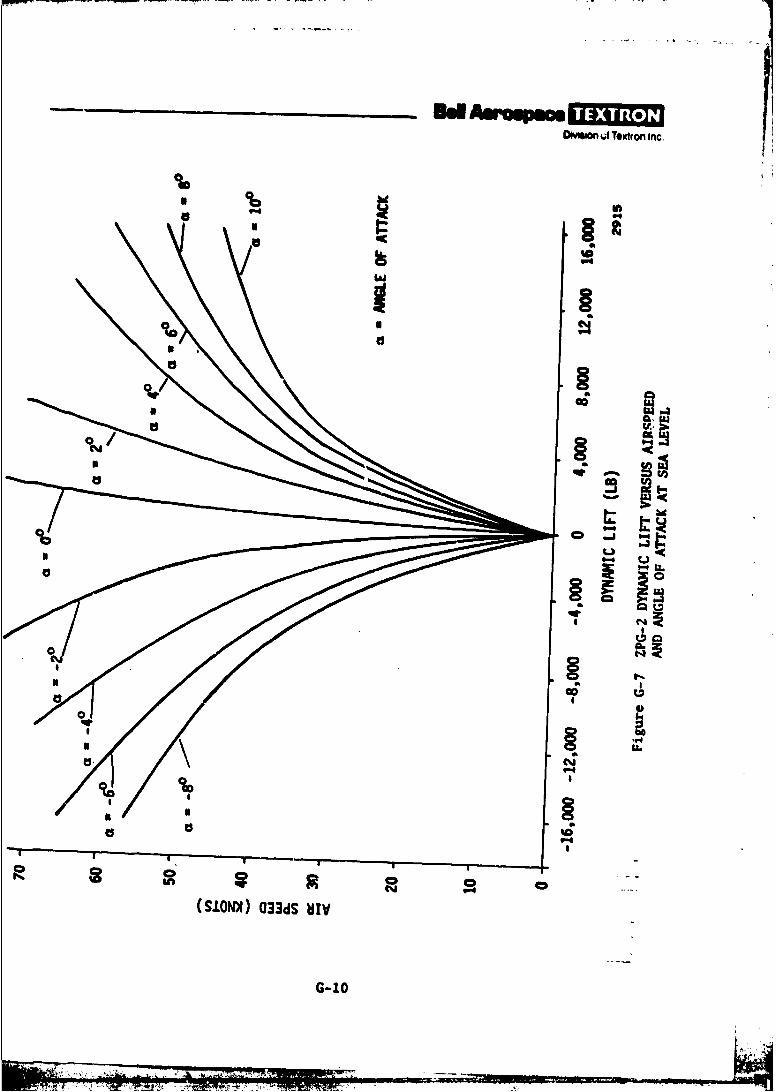
ODeso 04 Ttxtron ic.
940
C4
00
G-1
AM1
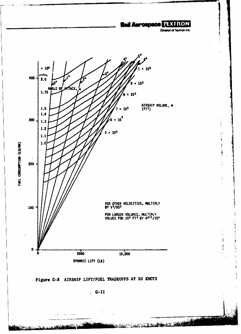
400 - 2.0 9 o
AIRSHIP VOLUM4E.
300.136 0
12002I1.0
FOR OTHER VELOCITIES, MULTIPLY100 By Vs/50'
FOR LARGER VOLMES, MULTIPLYVALUES FOR 106 VT3 By 4213/104
50sow 10,000
DYNAMIC LIFT (LB)
Figure G-8 AIRSHIP LIFT/FUEL TRADEOFFS AT SO KNOTS
G-11
[ Divimon of Textron Inc
G-S. AIRSHIP SIZING PROCEDURE
Taking the ELT mission as an initial example, the procedure was as follows:
a. Establish the total payload to be carried from the data in appendix E.
b. Select a reasonable trial value for the airship volume, and guess theamount of disposable load (ie, takeoff load minus return load). The dynamiclift required will be just half of that. Given the average dynamic lift andthe volume, the fuel consumption at SO knots can be found from figure G-8.
c. Multiply the fuel consumption, corrected for the proper speed, bythe mission time at each speed to get the total fuel-weight consumed. In theELT mission, most of the time is spent at SO knots, so assume that low speed,high speed, and hover conditions all balance out at about the same fuel con-sumption as at 50 knots, and let t- whole mission be taken as cruise atSO knots.
d. Divide the fuel weight by 0.9 to allow for a 10-percent reserve.
e. Add the resulting total f.uel weight to the total payload to get takeoffuseful load.
f. Subtract 90 percent of the fuel weight and the expendable payload
from the takeoff useful load to get the return useful load.
Ig. Half of the difference between the takeoff useful load and thereturn useful load is the maximum hover or takeoff rotor thrust required,and also the maximum dynamic lift requ.rad. This value ' hould check reasonablywell with the original assumption in step b, above. In using figure G-8,however, note that the maximum dynamic lift will occur only at the beginningof the mission, and the maximum negative dynamic lift only at the end, sothat the averagi is about half the maximum. Also note that the dynamic-lift-
S. versus-angle-of-attack curves are not symmetrical, thus this assumption isnot precise. Figure G-8 is for positive angles of attack.
* Ih. Iterate steps b through g until the dynamic lift is consistent withfuel consumption.
i. The propulsion module weight is assumed to be 5520 pounds, based onthe X-22A minus ducting (ie, with a free propeller).
J. The mass that an airship landing gear must decelerate is approximatelyproportional to the airship volume. Assume that about 0.00S x volume in ft3
is the weight in pounds of the landing gear, based on some preliminary estimates.
G-12
BW Asroopm[Ovihian of Textron Inc
k. The loads designing the outriggers and, therefore, the weight of theoutriggors are assumed to be proportional to the sum of the rotor thrust foundin step g, the weight of the propulsion system from step i, and the landinggear weight from step j. This assumes that the critical loading is a flightcondition with the MPA light and the rotor thrust acting dor, as distinguishedfrom the configuration of reference G-1 which cannot have downward thrust.Since the weight is also assumed proportional to the weight of the correspond-in& framework of reference G-1, see stop I, this may be conservative if the
Treference G-1 design is critical for a landing condition instead of a flight;~ Izondition.1. The o'triggor weight is also assumed proportional to its length.
The fineness ratio of the envelope is assumed to be 4.S, so that the radiusis 0.376 (volune)1/3. If the iNtersection of the plane of the rotors withthe envelope is at 30 degrees from the horizontal, and the clearance from the
[ rotor axis (based on reference 2) is 1.43 times the rotor radius, the outriggerlength is 1.43 RR + 0.326 (volume)1 /3. For purposes of weight estimation,the rotor radius RR is assumed to be 7 feet (rather than the 3.5 feet of theoriginal X-22A).
m. The framework weight is assumed to be proportional to the weight ofthe corresponding framework of the HLA operational design in reference G-1. TheLRTA frame is H-shaped in plan, and the longitudinal carry-through structure
Kis assumed to weigh half as much as the four outriggers.
n. The car weight is assumed to be 500 pounds per crew member, includingall crew dependent equipment such as seats, air conditioning, etc.
o. Instruments and standard equipment are assumed to weigh 1300 pounds,ba sed on reference G-3.
p. Thri airship empennage is assumed to weigh 1 lb/ft2 of area. Ther V area it taken from figure E-3 using the envelope volume arrived at in stepsb through h.
q. The fuel system is assumed to weigh 7 percent of the fuel weighti o of step d, based on reference G-4.
r. The sum of .11 weights, less the rotor or dynamic lift of steps g andh, is the net lift required of the envelope.
s. The weight of the envelope is assumed proportional to the net liftrequired, using the ratio for the 2,000,000-ft3 operational HLA of referenceG-1, whore it was 0.325. Since the envelope volume of the UPA must beincreased to enable the payload to be carried to 5000 feet without valvinghelium, the envelope weight is also increased by the appropriate air-densityfactor (0.8616 for S000 feet).
G-13
.. 7, . r
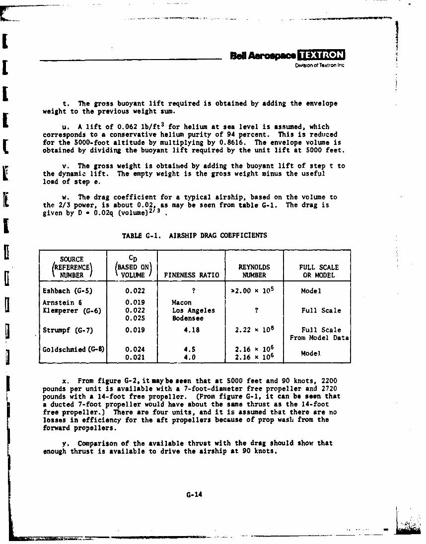
_ _ _ _ _ _ _ _ _ _ _ Ban Asop sDvision of Textron Inc
t. The gross buoyant lift required is obtained by adding the envelopeweight to the previous weight sum.
u. A lift of 0.062 lb/ft3 for helium at sea level is assumed, whichcorresponds to a conservative helium purity of 94 percent. This is reducedfor the 5000-foot altitude by multiplying by 0.8616. The envelope volume isobtained by dividing the buoyant lift required by the unit lift at 5000 feet.
v. The gross weight is obtaiiied by adding the buoyant lift of step t tothe dynamic lift. The empty weight is the gross weight minus the usefulload of step e.
w. The drag coefficient for a typical airship, based on the volume tothe 2/3 power, is about 0.02, as may be seen from table G-1. The drag isgiven by D - 0.02q (volume)2'3 .
TABLE G-1. AIRSHIP DRAG COEFFICIENTS
0 SOURCE CD
(REFERENCE) (BASED ON REYNOLDS FULL SCALENUMBER I VOLUME / FINENESS RATIO NUMBER OR MODEL
Eshbach (G-5) 0.022 ? >2.00 x 10⁵ Model
Arnstein & 0.019 MaconKlemperer (G-6) 0.022 Los Angeles ? Full Scale
0. 025 Bodensee
Strumpf (G-7) 0.019 4.18 2.22 x 10⁸ Full ScaleFrom Model Dat a
Goldschmied (G-8) 0.024 4.5 2.16 x 10⁶
0.021 4.0 2.16 x 10⁶ Model
x. From figure G-2, it maybe seen that at SO00 feet and 90 knots, 2200pounds per unit is available with a 7-foot-diameter free propeller and 2720pounds with a 14-foot free propeller. (From figure G-l, it can be seen thata ducted 7-foot propeller would have about the same thrust as the 14-footfree propeller.) There are four units, and it is assumed that there are nolosses in efficiency for the aft propellers because of prop wash from theforward propellers.
y. Comparison of the available thrust with the drag should show thatenough thrust is available to drive the airship at 90 knots.
G-14

A!
,[ Division of Textron Inc.
Iz. With the airship size obtained by this procedure, the fuel consumption
is rechecked. If the fuel consumption differs greatly from the originalassumption, the entire calculation must be iterated until reasonable agreementbetween initial and final values is reached.
aa. Two of the missions (SAR and MO/MP) include a significant amount
of towing. In the SAR mission, it is required to tow a small ship at 6 knotsfor 8.3 hours. A relationship between the drag of a ship in calm water andits length, velocity, and displacement is given on page 90 of reference G-9.Three specific vessels were fitted to the relationship to get the lower curvein figure G-9. The upper curve is an estimate assuming the drag to be doubled
in waves, plus an allowance for aerodynamic drag due to a 25-knot head wind.Comparison of figure G-9 with the airship drag suggests that the sum of shipdrag and airship drag at 6 knots should be no greater than the airship drag ata 70-knot airspeed. There is a downward force on the airship from the cabletension, but it is a function of the tow cable angle and is probably notcritical. Thus, for estimating fuel consumption, the SAR tow condition is assumedequivalent to the same amount of time at 60 knots.Ii bb. The MO/MP towing requirement is more complicated. A submerged arrayis to be towed at 10 knots, alternating with equal periods when the sonar
Sdevice is carried out of the water at 30 knots. The cable tension in thefirst case is estimated at 2300 pounds. The weight of the towed array is 1200pounds, exclusive of a 300-pound signal processor which remains or. board.
i Assuming that the drag of the array is such as to leave the vertical component
J of the cable tension at 1200 pounds avoids complications of vertical equilib-rium of the MPA and yields a drag of 1960 pounds during tow. This drag isadded to the estimated MPA drag at 10 knots and zero angle of attack; theairspeed giving the same drag without the tow is calculated and used as theequivalent speed for estimating fuel consumption. The resultant equivalentspeed was 55 knots. For the alternating periods when the array is carried inthe air, a drag of 100 pounds is estimated for the array. Adding this dragto the airship at 30 knots and zero angle of attack gives, for fuel consuaption,
an equivalent 32.5-knot airspeed.The results of the analyses are presented in table G-2. One significant result
is that the 9-knot dash requirement is easily met in all cases with the assumed
propulsion system, as are the VTOL thrust requirements. Superficially, itappears that the X-22A propulsion system is larger and heavier than needed for
1.the MPA. However, this does not take into accourt the desirability of the air-ship to hold position while hovering in a crosswind. Precision hover capabilityis a function of the thrust components available from the propulsion system, asdiscussed later. A propulsion system without reversible thrust, when the air-ship is at or near neutral buoyancy, must essentially be idling and, hence,
G-15
- a -.
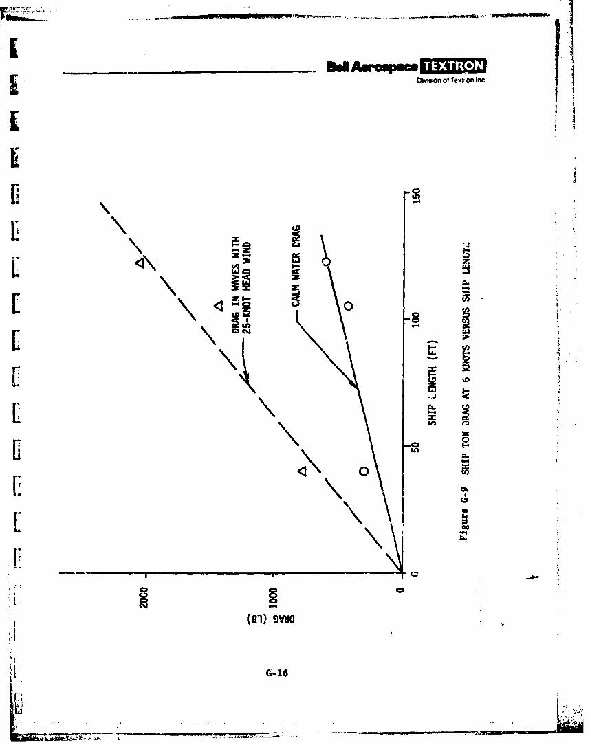
. B d- w.p - -]
-_Divison
of Text, on Inc.
i '4I i
zip
LU
EE>k-.
-C)-
iii
CCICD
G-16
L i.
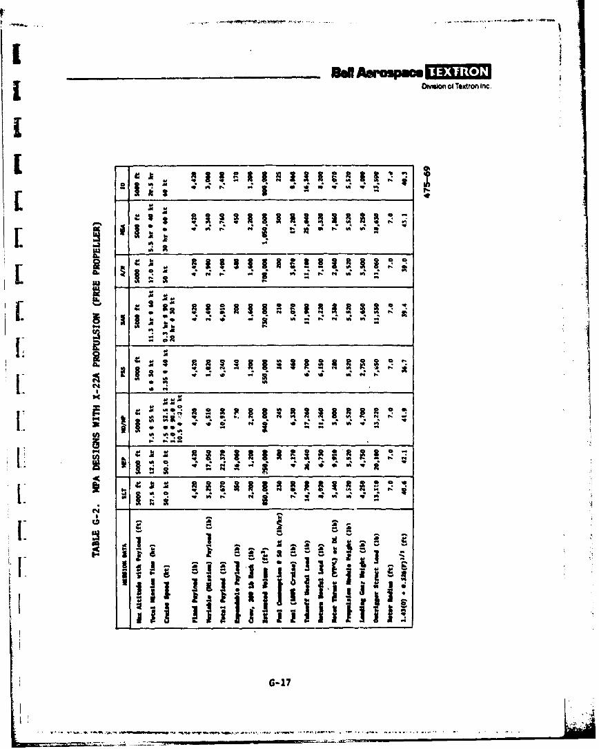
[ OMsion ci Textron Inc.
L 39
C44
G-1
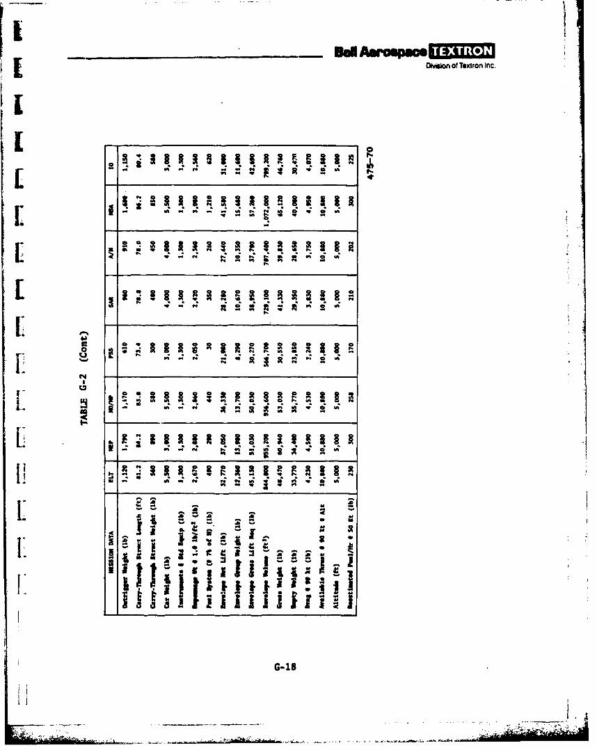
b
I Muion of Textron Inc.
l0
[" It .I I + I+ IIL4
I::
[ "+ - A 1 0 W+'+ -
52{
[ + G "-18,-I.; I: m, ;.o.
IiitI I~
N --
I- .. .:t. ',--~ .~ ..o- a u+ ;s
:1 + ' '+'; +9' :; ... .. ... + _ +" + ',,m'+ - "L: + 5 WI . ..... . '+ . ... ' . ..U ; ,+
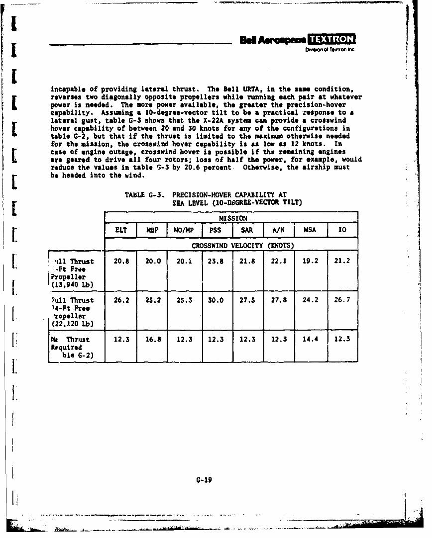
DOmow of Textron Inc
[incapable of providing lateral thrust. The Bell URTA, in the same condition,reverses two diagonally opposite propellers while running each pair at whateverpower is needed. The more power available, the greater the precision-hovercapability. Assuming a 10-degree-vector tilt to be a practical response to alateral gust, table G-3 shows that the X-22A system can provide a crosswindhover capability of between 20 and 30 knots for any of the configurations intable G-2, but that if the thrust is limited to the maximum otherwise neededfor the mission, the crosswind hover capability is as low as 12 knots. Incase of engine outage, crosswind hover is possible if the remaining enginesare geared to drive all four rotors; loss of half the power, for example, wouldreduce the values in table 5-3 by 20.6 percent. Otherwise, the airship must
Lbe headed into the wind.TABLE G-3. PRECISION-HOVER CAPABILITY AT[SEA LEVEL (IO-DF.GREE-VECTOR TILT)
MISSION
r.ELT I MEP IMO/MP_ P55 ] AIiI/E iNSA I10CROSSWIND VELOCITY (KNOTS)
-. ',all Thrust 20.8 20.0 20.1 23.8 21.8 22.1 19.2 21.2',Ft Free
1. j Propeller(13,940 Lb)
cull Thrust 26.2 25.2 25.3 30.0 27.5 27.8 24.2 26.7
14-Ft Free'ropeller ,(22,120 Lb) ._
Ith Thrust 12.3 16.8 12.3 12.3 12.3 12.3 14.4 12.3Required
ble G-2)
G-19
ed ---- call a 3- ODOrIm of Textron Inc
G.6. COMPARISON OF COMPUTER AND MANUAL AIRSHIP DESIGN APPROACHES
The computer design approach and the simplified manual design approach wereused in parallel to define a design for each of the specific missions. Someoverall comparisons can be mad* using the results in that general observationsof design trends can be made. However, no direct comparisons of the twodesigns can be made because the basic assumptions of the two approaches aresubstantially different.
Table G-4 briefly summarizes the differences between the computer and manualdesign approaches. The table lists most of the significant differences; theone most significant difference is in the propulsion system. The computerapproach uses a rubberized propulsion system whereas the manual approachuses a fixed, X-22A propulsion unit weight and thrust for all MPA sizes.
Figure G-10 shows the differences in the envelope volume obtained by the twoapproaches. The smaller the payload and mission duration requirement, thegreater the difference in the required airship volumes to accomplish the mis-sion. It takes extra volume to support the extra weight of the oversized,fixed propulsion system used in the manual approach. The computer designapproach, which minimizes the propulsion system weight for the mission require-ment, tends to give a much smaller airship volume for the smaller payloadrequirements. On tha other hand, for the higher payload missions, the MPAvolumes tend to be closer because the computer rubberized-propulsion-systemweights are closer to the fixed X-22A propulsion weights of the manualapproach.
Also contributing to the differences, the computer design uses the explicitmission profile specified for each case, while the manual design approachapproximates the profile. The manual approach designs for a 5000-footoperating altitude and the larger propulsion system always provides a 90-knotor greater dash speed, whether called for by the explicit.mission profileor not. There are also some differences in the drag coefficients assumed.
There is also some difference in the general philosophy of design in the twoapproaches. The computer airship design program is configured so that theairship is designed to have the buoyant lift support the vehicle empty weightplus S0 percent of the dispo3able load. This was done so that the airshipis designed to fly at the smallest possible angle of attack, minimizingdrag and, hence, fuel consumption. This design is then checked forthe horsepower required to achieve dash speed. If the horsepower requiredfor dash is less than that required for hover, such as in the MEP mission,the airship simply has a dash speed capability greater than that required.If, however, the dash speed requires a propulsion horsepower greater than thatrequired for hover, as in the ELT, MO/MP, and SAR missions, the dash propulsion
G-20

__ __ __ __ _ d Am -pt
omw nof TXtron Inc
144#A 0
Sd
vi C_____ ____ _____ ___ v Q.
dW/OW \wm
4A Q
IS
nC3
(tcu 000!) 3Wfl10A
G-21
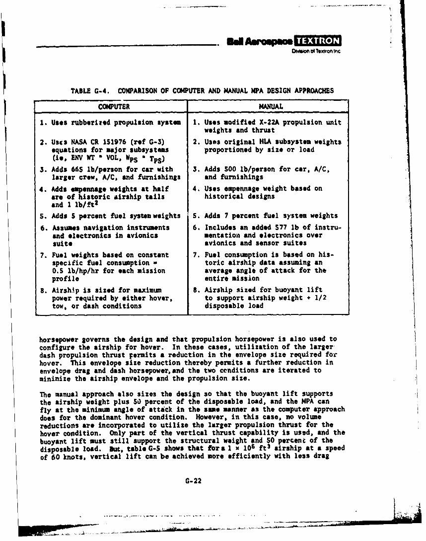
_________ inAwape= ITTDimsion 04 teron Inc
TABLE G-4. COMPARISON OF COMPUTER AND MANUAL NPA DESIGN APPROACHES
COMPUTER MANUAL
1. Uses rubberized propulsion system 1. Uses modified X-22A propulsion unitweights and thrust
2. Uses NASA CR 151976 (ref G-3) 2. Uses original HLA subsystem weightsequations for major subsystems proportioned by size or load(ie, ENV WT * VOL, Wps a Tps)
3. Adds 665 lb/person for car with 3. Adds 500 lb/person for car, A/C,larger crew, A/C, and furnishings and furnishings
4. Adds empennage weights at half 4. Uses empennage weight based onare of historic airship tails historical designsand 1 lb/ft2
S. Adds S percent fuel system weights S. Adds 7 percent fuel system weights
6. Assumes navigation instruments 6. Includes an added 577 lb of instru-and electronics in avionics mentation and electronics oversuite avionics and sensor suites
7. Fuel weights based on constant 7. Fuel consumption is based on his-specific fuel consumption a toric airship data assuming an0.5 lb/hp/hr for each mission average angle of attack for theprofile entire mission
8. Airship is sized for maximum 8. Airship sized for buoyant liftpower required by either hover, to support airship weight + 1/2tow, or dash conditions disposable load
horsepower governs the design and that propulsion horsepower is also used toconfigure the airship for hover. In these cases, utilization of the largerdash propulsion thrust permits a reduction in the envelope size required forhover. This envelope size reduction thereby permits a further reduction inenvelope drag and dash horsepower, and the two cenditions are iterated tominimize the airship envelope and the propulsion size.
The manual approach also sizes the design so that the buoyant lift supportsthe airship weight plus 50 percent of the disposable load, and the MPA canfly at the minimum angle of attack in the same manner as the computer approachdoes for the dominant hover condition. However, in this case, no volumereductions are incorporated to utilize the larger propulsion thrust for thehover condition. Only part of the vertical thrust capability is used, and thebuoyant lift must still support the structural weight and 50 percent of thedisposable load. But, table G-S shows that fora I x 106 ft 3 airship at a speedof 60 knots, vertical lift can be achieved more efficiently with less drag
G-22
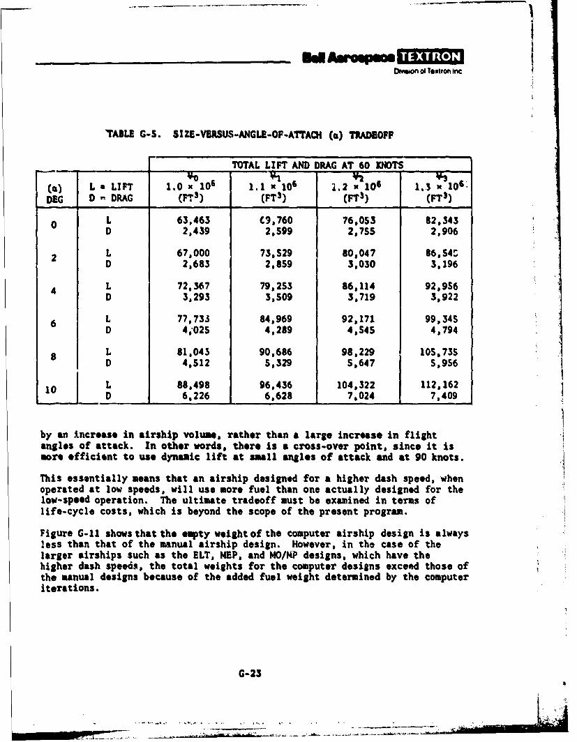
I
_ _ _ __ _ _ __ heAwompmOww~of of Textron Inc
'AILE G-S. SIZ-VERSUS-ANGLE-OF-A'rACH (ca) TRADEOPF
TOTAL LIFT AND DRAG AT 60 KNOTS
(i) L • LIFT 1.0 x 10⁶ 1.1 106 1.2 x 10⁶ 1.3 : 106'DEG D DRAG (T 3) (FTS) (FT') (FT3)
0 L 63,463 C9,760 76,053 82,343D 2,439 2,S99 2,?S 2,906
2 L 67,000 73,S29 80,047 86,54'D 2,683 2,859 3.030 3,196
L 72.367 79,253 86,114 92,956D 3,293 3,509 3,719 3,922
6 L 77,733 84,969 92,171 99,345D 4,025 4,289 4,545 4,794
8 L 81,043 90,686 98,229 105,73SD 4,512 5,329 S,647 5,9S6
10 L 88,498 96,436 104,322 112,162
D 6,226 6,628 7,024 7,409
by an increase in airship volume, rather than a large increase in flightangles of attack. In other words, there is a cross-over point, since it ismore efficient to use dynamic lift at small angles of attack and at 90 knots.
This essentially means that an airship designed for a higher dash speed, whenoperated at low speeds, will use more fuel than one actually designed for thelow-speed operation. The ultimate tradeoff must be examined in terms oflife-cycle costs, which is beyond the scope of the present program.
Figure G-11 shows that the empty weight of the computer airship design is alwaysless than that of the manual airship design. However, in the case of thelarger airships such as the ELT, MEP, and MO/MP designs, which have thehigher dash speeds, the total weights for the computer designs exceed those ofthe manual designs because of the added fuel weight determined by the computeriterations.
G-23
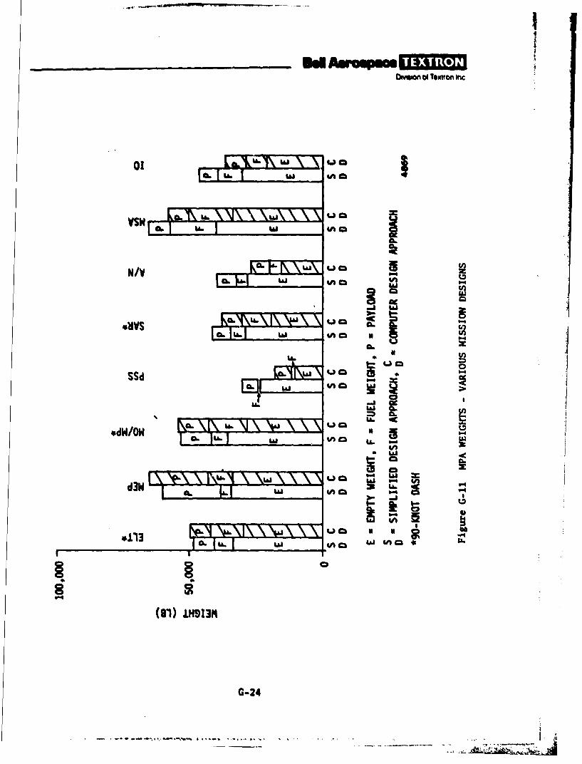
Oamio of Textron Inc
01
N/V KFFj\w0ui #A
4.WS Q.I
ss %n. m
w c*113L W
UJI ~ ~ 4Acm 4
(81)O 1HO13M~
C. L. G-24L

I
OMMon of Tooon Inc
RUFERENCES
G-1. Feaibiity of Modern Airship--Phase ZI (Goodyear Aerospace Corporation,NASA CR-IS1917, September 1976) volume I, book I.
G-2. J. W. Lancaster, ZPG-X Design and Performance Charaoterietioe for AdvanoedNaval Operations (Melbourne, Fla: AIAA Lighter Than Air Systems Tech-nology Conference, Paper 77-1197, August 11-12, 1977).
G-3. Development of Weight Estimating Relationships for Rigid and Non-RigidHeavy Lift Airships (Goodyear Aerospace Corporation, NASA CR-1S1976,March 1977).
G-4. Feasibility of Modern Airships Final Report--Phase X (Boeing VertolCompany, NASA CR-137691, May 1975) volume I.
G-S. 0. W. Eshbach (ed), Handook of Engineering Pundmentals (New York:John Wiley 4 Sons, second edition, 1952).
G-6. K. Arnstein and W. Klemperer, Perfomanoe of Airships (AerodynamicTheory, W. F. Durand (ed), New York: Dover Publications, Second Edition,1963) volume VI.
G-7. Albert Strumpf, An Analyee of the 2Uwning rTharateriatios of the ZZPAirship Based upon Underater, Foroed-2Urning Model &periements(Stevens Institute of Technology, Report SIT-DL-54-S34, October 1954).
G-8. F. R. Goldschmied, Aerodynomio HuZ Deeign for JASPA LTA Optimixation(Journal of Aircraft, September 1978) volume 1S, no. 9, pp 634-638.
G-9. H. E. Rossell and L. B. Chapman (ods), PrinaipZes of Naval Arohitecture(New York: Society of Naval Architects and Marine Engineers, 1958)volume II.
G-2S

Oivsion of Textron gnc.
II
1'
" I .APENDIX
- FUEL CONSUMPTION ANALYSIS
I
I
"" I
1
Divmion of Textron Inc
For the computer analysis, a single large propulsion unit with a specificfuel consumption (SFC) of 0.5 lb/hp/hr was used as a simplifying assumptionto generate the airship parametric data in this report.
This assumption is valid because there are several counterbalancing factorsthat affect the fuel consumption. The SFC of gas turbinss is normallysensitive to throttle setting, and when the engine is not being run at maximumrated power, the SFC can increase significantly. On the other hand, a largernumber of propulsion units is more efficient than a smaller number of units.Moreover, the staging of multiple units is also possible.
However, because the missions for the MPA require large amounts of time at lowspeed, the computer program was later modified for subsequent design studiesand to investigate the validity of the simplifying assumption of constant SFC(assumption A). A brief investigation based on Advanced Naval Vehicle ConceptEvaluation (ANVCE) fuel consumption studies (reference H-l) was made, takinginto account not only the increased SFC at low power, but also the quad-rotordesign, which allows one, two, or three engines to be shut down during loiteror low-speed periods of a mission (assumption B). The results are compared infigure H-1 for the ELT mission and in table H-1 for best ELT mission designs.
As the table shows, the assumption of SFC a 0.5, as compared with assumption Bwith the minimum SFC - 0.5, is optimistic by 2 or 3 percent on volume andvehicle weight and by 7 percent on fuel weight in this example. Therefore,the results in the main body of this report correspond to a minimum SFC ofslightly lower than 0.5. Such differences appear to be well within thetolerance of the other analysis assumptions. If, however, for future analysis,it I.s desired to incorporate the refinement of variable throttle settings, thecapability now exists in the program to do so.
REFERENCE
H-1. Standard Power PZant Charaoterietioe for Advanoed NavaZ Vehio # in the1980-200 Time Period (ANVCE Working Paper 011, Initial Issue, August 31,1976).
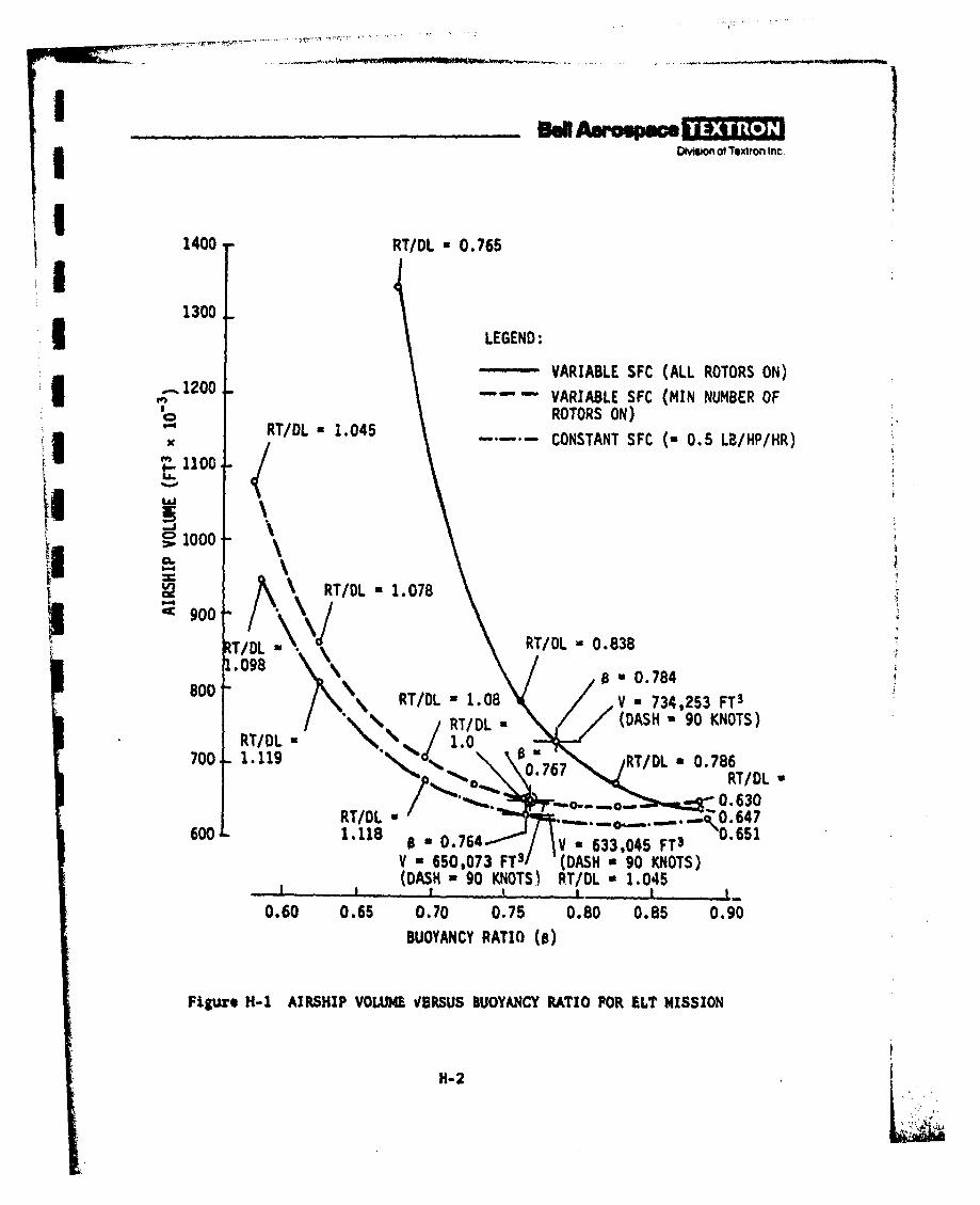
_ __ __ __ _ SdAermpace A O4mIlon of Textron Inc,
1400- RT/DL *0.765I1300
LEGEND:
VARIABLE SFC (ALL ROTORS ON)I .120 - " VARIABLE SFC (MIN NUMBER OF
ROTORS ON)~RT/DL =1.045
1 -/-..... CONSTANT SFC (u 0.5 LB/HP/HR)
tJJ
~100CL.
12 RT/DL 1.078S900
T/DL RT/DL 0.838
1.980 u 0.784800 RT/DL -1.08Va73,5 T
/TD (DASH -90 KNOTS)RT/DL 1.
700 .119RT/DL *0.7860.767RT/DL
0.630RT/DL * .. * 7
600 -1.118 0.651
V *650,073 FT3 (DASH a 90 KNOTS)(DASH a 90 KNOTS) RT/DL - 1.045
0.60 0.65 0.70 0.75 0.80 0.85 0.90
BUOYANCY RATIO (0)
Figurs H-i AIRSHIP VOLUME VtIRSUS BUOYANCY RATIO FOR ILT MISSION
H- 2
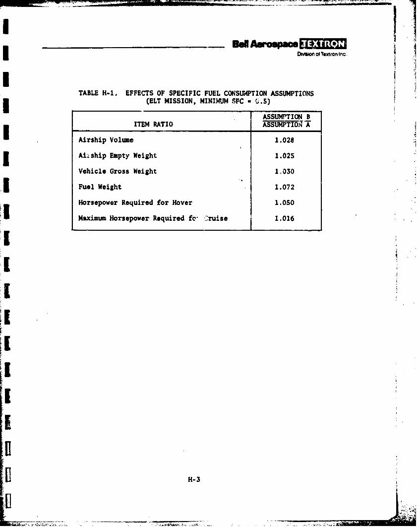
Divsion of Textron Inc.
TABLE H-l EFFECTS OF SPECIFIC FUEL CONSUMPTION ASSUMPTIONS(ELT MISSION, MINIMUM SFC C.5)
ASSUMPTION BITEM RATIO ASSUMPTION A
Airship Volume 1.028
Aiship Empty Weight 1.02S
Vehicle Gross Weight 1030
Fuel Weight 1.072
Horsepower Required for Hover 1.0SO
Maximum Horsepower Required fe- ruise 1.016
H-3
I.
I%:°
I/
O mo ofrTolrorn Inc .
.I
! II

_________en Asropace1 *ONMen of xtron Inc
1-1. INTRODUCTION
To investigate the weight of some major subsystems, calculations were made toinvestigate outrigger and framework weights, and landing gesr and flotation gearweights. For these calculations, a typical airship volume of 800,000 ft3 wasused with a maximum envelope radius of 36 feet. In most of the analysis, loadswere based on an early MPA mission configuration, but each rotor was assumedto deliver a maximum thrust of 3500 pounds, based on the X-22A propulsionI system. 12 ~
1-2. FRAME
A brief investigation of the best method of supporting the propulsion unitsand the car was made, The propulsion units are assumed to be centered alonga line that is 45 degrees below the horizontal from the center of the envelope,and that extends 45 feet from the envelope center. The car weight is assumedconcentrated at the vertical centerline. Also, the propulsion units are assumedto be 54 feet apart, forward to aft.
The three different basic types of structure considered were a yoke design,consisting of outriggers extending out from the car and upward along the
*envelope to the level of the propulsion units, a stiff ring support runningaround the full circumference of the envelope, and a spoked ring, otherwisesimilar to the stiff ring. A limit load factor of 1.5 with the usual 1.5factor of safety for aircraft was assumed; however, the use of large amountsof rotor or dynamic lizt will increase g-loadings over those experienced byconventional, fully buoyant airships.
A triangular truss goction made of welded 6061-T6 round tubing was assumedfor the ring, and compared with a similar yoke design. Tht weight of the carand carry-through structure is assumed carried out in the internal suspensionsystem without causing any bending moment in the carry-through structure.Also, half of the engine thrust loads are carried into the envelope throughthe internal suspension, and half through an external suspension. Essentially,the carry-through structure is assumed to be a uniformly loaded beam on endsupports. With the ring design, it is assumed that at least most of the carloads would be transferred by bending of the carry-through structure to therings, rather than through the suspension system, and thence to the envelope.The ring bending moments were calculated using conventional ring equa&. ,assuming the engine and car load components as concentrated normal and shear-ing forces and couples.
-The estimated weight of the rings, carry-through structure, and outriggerswas 4888 pounds, and for the yoke design and carry-through structure, 2373pounds. However, the suspension system for the ring design might be partiallyor oven entirely eliminated.
IIl
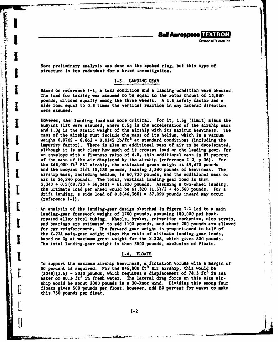
Oivlsin of Text=o Inc
Some preliminary analysis was done on the spoked ring, but this type ofstructure is too redundant for a brief investigation.
1-3. LANDING GEAR
Based on reference 1-1, a taxi condition and a landing condition were checked.The load for taxiing was assumed to be equal to the rotor thrust of 13,940pounds, divided equally among the three wheels. A 1.5 safety factor and aside load equal to 0.8 times the vertical reaction in any lateral directionwere assumed.
However, the landing load was more critical. For it, 1.Sg (limit) minus thebuoyant lift were assumed, where O.Sg is the acceleration of the airship massand 1.Og is the static weight of the airship with its maximum heaviness. The
i mass of the airship must include the mass of its helium, which in a vacuumweighs 0.0765 - 0.062 - 0.0145 lb/ft3 at standard conditions (including theimpurity factor). There is also an additional mass of air to be decelerated,although it is not clear how much of it creates load on the landing gear. Foran envelope with a fineness ratio of 4.5, this additional mass is 87 percentof the mass of the air displaced by the airship (reference 1-2, p 36). Forthe 845,000-ft3 ELT airship, the estimated gross weight is 48,470 poundsand the buoyant lift 45,130 pounds, leaving 3,340 pounds of heaviness. Theairship mass, including helium, is 60,720 pounds, and the additional mass ofair is 56,240 pounds. The total, vertical landing-gear load is then3,340 + 0.5(60,720 + 56,240) a 61,820 pounds. Assuming a two-wheel landing,the ultimate load per wheel would be 61,820 (1.5)/2 + 46,360 pounds. For adrift landing, a side load of 0.8(46,360) a 37,090 pounds inward may occur(reference 1-1).
LAn analysis of the landing-gear design sketched in figure 1-1 led to a mainlanding-gear framework weight of 1700 pounds, assuming 180,000 psi heat-treated alloy steel tubing. Wheels, brakes, retraction mechanism, oleo struts,and bearings are estimated to add 1100 pounds, and about 200 pounds are allowedfor car reinforcement. The forward gear weight is proportioned to half ofthe X-22A main-gear weight times the ratio of ultimate landing-gear loads.based on 3g at maximum gross weight for the X-22A, which gives 500 pounds.The total landing-gear weight is then 3500 pounds, exclusive of floats.
1-4. FLOATS
To support the maximum airship heaviness, a flotation volume with a margin of50 percent is required. For the 845,000 ft3 ELT airship, this would ber(3340)(1.S) ; S010 pounds, which requires a displacement of 78.3 ft3 in seawater or 80.3 ft3 in fresh water. The lateral drag force on this size air-ship would be about 2000 pounds in a 30-knot wind. Dividing this among fourfloats gives 500 pounds per float; however, add SO percent for waves to makethis 750 pounds per float.
Li 1-2
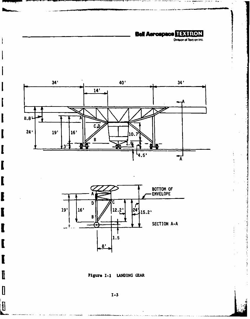
..... . . .
- ...- _ ' . . ._. ' *_ - .... .. ,- ". .. , ,- -
Division of Textron Inc
I 34' 40' 34'
8.8
IABOTTOM OF : ,
2,19' 16' 122' 2' 15.2
' " SECTION A-A
1.57
" 8'
I. .
flFigue I-i LNDING GEAR
S1-3
B"

_ _ _ _ _ _ _ _ _ _ _ d AaMmpoOMson ot Textron Inc
A relation between the diameter (d) and the immersion (x) for a cylindricalfloat (in sea water) is
(64t)(d 2/4)(x) - 78.3(1728)/4 * (I-)
Also, for bending,
I/c * wd/16 . (I-2)
The critical condition is assumed to occur when the bending compressive stressplus the axial compressive stress, due to the weight supported, equals thetension in the fabric due to the inflation pressure at limit loads:
pd/4 a Mcll + P/wd (1-3)
(The actual collapse moment will, for practical fabric materials, be more than1.5 times as great as the critical moment defined by this relationship). Theside load for bending is assumed to be uniformly distributed below the water.For the aft floats, the maximum bending moment is assumed to occur at thewater surface where the float can be assumed to be supported by the landinggear. For the forward floats, the bending moment is assumed to be approxi-mately 3 times as great. By eliminating x from equations (I-1) and (1-3)(M being a function of x), an equation of the form
Ad6 - Bd4 - C - 0 (1-4)
[may be obtained and solved by trial for d, provided the inflation pressure (p)is known.
The maximum permissible value for p is limited by the fabric strength. Assumea maximum fabric strength of S00 lb/inch, and a factor of safety of 5 to coveroverload, material degradation, and creep or fatigue phenomena. Then, sincethe hoop stress is pd/2, p - 200/d, and the equation to be solved is reducedto fifth order. Table I-1 gives the results.
Assuming a strength-to-weight ratio of 300,000 inches for a coated fabricsuitable for this application, the fabric weight for two forward floats isabout 76 pounds and for the aft floats, 70 pounds. To this should be addedthe weight of the compressed air inflating the floats (a total of about 13pounds), about 10 percent for seams, and an increment for canisters, pumps,
I*For four floats.
1-4
LI

OMmIon of Textron Inc.
TABLE I-1. RESULTS
Aft Floats Forward Floats
d -19.3 in. d a24 in.
x a9.63 ft x a6.2S ft
p 0.6 psi p .S3 psi
attachments, etc; these are assumed to double this weight to give a total ofaround 400 pounds for all four floats.
The forward floats might be supplemented or perhaps replaced by a simple bagfloat under the pilot's compartment.
The system could further include sea anchors. These might be placed at theforward outriggers, if floats are not extended there, and at the nose and tail.A winching system would be required, plus compartments for storing the seaanchors. Local loads on the envelope would require reinforcement. If seaanchors are not used, however, it will be necessary to use floats extendingdeeper into the water than the above calculations assumed, in order to reducevertical motions due to wave action. An allowance of an additional 350 poundsis included in the landing-gear weight (which includes floats and/or sea anchors)in table G-2 of appendix G to give a total weight of 4250 pounds.
REFERENCES
1-1. GOrowd Load& (Issued by the Subcommittee on Air Force-Navy-Civil AircraftDesign Criteria of the Munitions Board Aircraft Committee, U.S. Govern-ment Printing Office, October 1952) ANC 2.
1-2. Aer'odymzmo 2teory (New York: Dover Publications, Inc., William F.Durand, ed., 1963) volume VI, p 36.
I-s
/,