ADIB27 R&D PLAN FOR ARMY APPLICATIONS OF AI ... - DTIC
325
A-IS27 SRI INTERNATIONAL MENLO PARK CA F/S A/A ADIB27 R&D PLAN FOR ARMY APPLICATIONS OF AI/RO8OTICS.MU MAY 82 D ft BROWN. D V FOULER,0 .J FRIE OAAK0-t-C-0250 UNCLASSIFIED ETL-0296 NL
-
Upload
khangminh22 -
Category
Documents
-
view
3 -
download
0
Transcript of ADIB27 R&D PLAN FOR ARMY APPLICATIONS OF AI ... - DTIC

A-IS27 SRI INTERNATIONAL MENLO PARK CA F/S A/AADIB27 R&D PLAN FOR ARMY APPLICATIONS OF AI/RO8OTICS.MU
MAY 82 D ft BROWN. D V FOULER, 0 .J FRIE OAAK0-t-C-0250UNCLASSIFIED ETL-0296 NL

' ETL.0298
R&D PLAN FORARMY APPLICATIONS
-OF Al/ROBOTICS
Final Report
May 1982
By: David R. Brown, Project LeaderDarrell V. FowlerDavid J. FrieWilliam M. HadlyJoan C. Introne D TIWilliam T. Park
Ann E. Robinson ,William Schubert .'AUG 1 7 1982
Prepared for:
U.S. Army Engineer Topographic LaboratoriesFort Belvoir, Virginia 22060
Contract No. DAAK70-51-C-0250SRI Project 3736
C-LCt_ APPROVED FOR PUBLIC RELEASE; DISTRIBUTION UNLIMITED
SRI International333 Ravenswood AvenueMenlo Park, California 94025(415) 326-6200Cable: SRI INTL MPKTWX: 910-373-2046
82 08 16 ,-,,37

UNCLASSIFIEDSECURITY CLASSIFICATION OF THIS PAGE (When Date Entered)
READ INSTRUCTIONSREPORT DOCUMENTATION PAGE BEFORE COMPLETING FORM
I. REPORT NUMBER 2. GOVT ACCESSION NO. 3. RECIPIENT'S CATALOG NUMBER
ETL-0296 ii9/f 974. TITLE (and Subtitle) S. TYPE OF REPORT & PERIOD COVERED
R&D PLAN FOR ARMY APPLICATIONS Final Report
OF Al/ROBOTICS 6. PERFORMING ORG. REPORT NUMBER
SRI Project 3736
7. AUTHOR(s) S. CONTRACT OR GRANT NuMBER(s)
* David R. Brown, Darrell V. Fowler,David J. Frie, William M. Hadly, Joan C. Introne DAAK70-81-C-0250William T. Park, Ann E. Robinson, William Schubert9. PERFORMING ORGANIZATION NAME AND ADDRESS 10. PROGRAM ELEMENT. PROJECT, TASKSRI International AREA & WORK UNIT NUMBERS
333 Ravenswood Avenue
Menlo Park, California 94025
It. CONTROLLING OFFICE NAME AND ADDRESS 12. REPORT DATE
U.S. Army Engineer Topographic Laboratories May 1982
Fort Belvoir, Virginia 22060 13. NUMBER OF PAGES
32414. MONITORING AGENCY NAME A ADDRESS(f dilferent from Controlling Office) IS. SECURITY CLASS (of this report)
Unclassified
IS*. DECL ASSI FICATION/DOWNGRADINGSCHEDULE
16, DISTRIBUTION STATEMENT (of this Report)
Approved for Public Release; Distribution Unlimited
17. DISTRIBUTION STATEMENT (of the abstract entered in 3lock 20, it dllferent from Report)
18. SUPPLEMENTARY NOTES
19. KEY WORDS (Continue on reveree side if necessary end identify by block number)
Artificial intelligenceResearch managementRobots
4 Tactical warfare
ABSTRACT (Continue on reverse side Of necessary and identify by block number)
One hundred applications of artificial-intelligence technology and robotics in
Army combat and combat support that may be possible and worthwhile are identi-fied. These possible applications have been divided into ten categories, andone example in each category has been examined in detail. Research anddevelopment plans have been developed showing the basic and applied researchthat would be needed to make the applications possible.,.\Although the numberof possible applications is large, the number of key tfechhology elements is
DDFORM17 EDI JAN 73 * O, TON OF I NOV 65 IS OBSOLETE USE URI3 CLA3SSFCT O T UNCLASSIFIED
SECURITY CLASSIFICATION OF THIS PAGE ("aen Data Entered)
L i Z

UNCLASSIFIEDSIECUmITY CLASIICATION OF THIS PAeG(N*An om &W*
20. ABSTRACT (continued)
relatively small, and many of the same technology elements are required inmany different applications.
Access5ion For
NTIS GRP&t
DTIC TAB0
uz'annocd
By
Distributionl/ _
b 'ea AvailabilitY Codes
~ Diet special
UNCLASS IFIEDSCUMITY CLASSIFICATION OF THIS PAGE(Whe bets Ent.,.d)

EXECUTIVE SUMMARY
The study reported here is intended to help shape the Army's
research and development plan for applications of artificial
intelligence (Al) and robotics in combat and combat support.
An intelligent robot should be able to think, sense, and effect.
Thinking is primarily a brain function. Sensing (seeing and touching)
and effecting (moving and manipulating) are primarily body functions.
The thinking function executed by a computer is the domain of artificial
intelligence. Sensing and effecting are based on physics, mechanical
engineering, electrical engineering, and computer science. Planning and
execution of tasks entail both brain and body functions and are concerns
of both artificial intelligence and robotics. No attempt is made in
this report to distinguish between artificial intelligence and robotics;
instead, a unified model that encompasses both is proposed.
The unified model of AI/robotics is illustrated below.
WORLD MODEL
REASONING
INTERPRETING GENERATING
A UNIFIED MODEL OF ARTIFICIAL INTELLIGENCE AND ROBOTICS

The approach to identification of potential applications of
AI/robotics in Army combat and combat support is comprehensive and
methodological. Five tasks were involved in the approach.
(1) Data Collection--Identifying, assembling, and/orextracting pertinent studies and doctrinal/conceptpublications, and reviewing current Army thinking throughcontact with major Army agencies (Section 2.1).
(2) Application Concept Derivations--Analyzing combat/combatsupport from six distinctly different viewpoints:threats, units, equipment, functions, environmenti-andpersonnel (Section 2.2).
(3) Technological Possibilities Appraisal--Appraisingfeasibility of concepts (based on Section 3).
(4) Synthesis of Application Categories--Synthesizinganalyzed information on application concepts andtechnical possibilities into meaningful categories forresearch (Section 4.1).
(5) Detailed Application Examples and Design Criteria-Preparing descriptions of potential examples illustratingeach category of application, and defining criteria toguide research activities in each of the applicationcategories (Section 4.2).
This approach resulted in identification of 100 specific concepts
for Al/robotics combat/combat-support systems. Because of this large
number of concepts, the concepts were used as a basis for defining ten
broad categories of applications. The application categories were
selected according to three criteria:
* Technological Similarity--Concepts in a group require
advances in similar technical areas of AI/robotics.
* Military Use--Each category should pertain to arecognizable element of military activities.
* Comprehensiveness--The categories should encompass all
potential combat/combat-support AT/robotics applications,as illustrated by the derived concepts.
The ten categories thus defined are:
(1) Human/Equipment Interface Aids
(2) Planning and Monitoring Aids
(3) Expert Advisors
2

(4) Data Assimilation and Access Aids
(5) Handling Support Systems
(6) Support Systems
(7) Situation Assessment Systems
(8) System Controllers
(9) Weapons
(10) Information Collectors
To develop and demonstrate objectives, approaches, and
methodologies for Al/robotics, an example was chosen from each of the
ten categories for further study. The examples chosen were:
Category Example
1. Human/Equipment Interface Aids Division Commander's QuickData-Access System
*2. Planning and Monitoring Aids Brigade Mission Planning Aid3. Expert Advisors Emergency Repair and
Maintenance Advisor4. Data Assimilation and Access Aids Interrogation Support System5. Handling Support Systems Tank Ammunition Handler6. Support Systems Mine Clearer7. Situation Assessment Systems Tactical Threat Projection
System8. System Controllers Safe Return Controller9. Weapons Light Fighting Sentry10. Information Collectors River Reconnaissance System
Each of the ten examples is described in detail, including need,
employment concept, capabilities, organizational distribution, physical
design, technology gaps, and evolutionary versions. The technology gaps
provide the basis for the research plan.
The recomi~ended research plan consists of fundamental research,
specific research tasks, and system considerations. Included in the
repearch plan for Al/robotics are five fundamental research areas, 97
specific research topics, and eight system considerations. Research on
some supporting technologies is required.
Most potential applications will require advancement of the
technology base (6.1 and 6.2) before advanced development (6.3) of the
3

applications can be started. With the capabilities ascribed to the ten
examples, the study estimated that development could be started on only
four during the next ten years. Two of the ten examples would require
deferral of development until the year 2000.
However, early starts for development of Al/robotics applications
may be possible if applicatiogs witoh less capability are developed. The
study identified four of the ten candidate applications as examples that
could be developed now, with essentially today's technology. These
candidate applications are:
Mine ClearerBrigade Mission Planning AidTank Ammunition HandlerDivision Commander's Quick Data-Access System
These applications also rank favorably when benefits, costs, and
risks are considered. However, no evaluation was attempted of all of
the 100 specific Al/robotics concepts as candidates for development with
today's technology.
Successful future applications of AI/robotics will require that
research plans include system considerations, such as feasibility
studies, development tools, system integration, and modularity. Both
hardware and software modules that would be common for a number of
applications appear to be possible. Much of the evolution of
AI/robotics systems should be possible by means of module replacement,
especially by the upgrading of software modules.
Countermeasures and counter-countermeasures should also be included
in the research plan as system considerations.
Although some of the ten examples that were studied in detail are
long range, such as the Light Fighting Sentry and River Reconnaissance
System, the research that would make these examples possible is
necessary in order to realize important functions that will be vital for
many Army applications in the future.
4

Conclusions
To summarize the foregoing discussion, the conclusions of the study
of an R&D plan for Army applications of Al/robotics are as follows:
(1) AI/robotics will significantly enhance the capabilitieaof the Army.
(2) A unified model of artificial intelligence and roboticscan be postulated and successfully applied for Army R&Dplanning in Al/robotics.
(3) The number of potential applications of AI/robotics i1Army combat and combat support is large. One hundredconcepts were identified.
(4) The 100 concepts can be divided into ten categories ofapplications, based primarily on combat and combat-support functions. These categories are:
Human/Equipment Interface AidsPlanning and Monitoring AidsExpert AdvisorsData Assimilation and Access AidsHandling Support SystemsSupport SystemsSituation Assessment SystemsSystem ControllersWeaponsInformation Collectors
(5) There are a number of gaps between the current state-of-the-art in Al/robotics and the technology required torealize the application. These technology gaps, orresearch tasks, provide a basis for a research plan that
supports the development of the exemplary concepts andother applications of Al/robotics in Army combat andcombat support.
(6) The required research consists of fundamental research,specific research tasks, and system considerations. Theresearch can be organized into five fundamental researchtopics, 97 specific research topics (in sensing,interpreting, reasoning, generating, and effecting), andeight system considerations. In addition, research onsome support technologies is required.
(7) Most of the research tasks support multiple applications,and several common system modules could be identified.
(8) Additional study and evaluation of the 100 concepts areneeded. Such studies are needed primarily to definebetter objective applications of AI/robotics to Armycombat and combat support, and secondarily to improve the
5

definition of the research plan presented here. The planincludes research to obtain information required to make
future decisions about research priorities andapplication objectives.
(9) Most potential applications will require advancement of
the technology base (6.1 and 6.2) before advanceddevelopment (6.3) of the applications can be started.With the capabilities ascribed to the ten examples, the
study estimated that development could be started on onlyfour during the next ten years. Two examples wouldrequire deferrment of development until the year 2000.
(10) Early starts for development of AI/robotics applicationsare possible if applications with less capability,
evolutionary versions of the objective applications, aredeveloped. The study identified four of the ten examplesas candidate applications that could be developed now,without advancement of the technology base. Thesecandidate applications are:
Mine Clearer
Brigade Mission Planning AidTank Ammunition HandlerDivision Commander's Quick Data-Access System
(11) Successful future applications of AI/robotics willrequire the inclusion of system considerations inresearch plans, such as feasibility studies, developmenttools, system integration, and modularity. Both hardwareand software modules that would be common for a number ofapplications appear to be possible. Much of theevolution of Al/robotics systems should be possible bymeans of module replacement, especially by the upgradingof software modules.
(12) Countermeasures and counter-countermeasures should alsobe included in the research plan as systemconsiderations.
(13) Although some of the ten examples that were studied indetail are long range, such as the Light Fighting Sentryand River Reconnaissance System, the research that wouldmake these examples possible should be supported becauseit addresses important functions such as mobility,navigation, and identification of targets, that will bevital for many Army applications in the future.
Recommendations
In accordance with the findings of this study, the following
recommendations are made:
6

Recommendations
In accordance with the findings of this study, the following
recommendations are made:
(1) Advance the state-of-the-art in Al/robotics and develop atechnology base for Al/robotics through:
Fundamental research 5 tasksSpecific research tasks:
Sensing 6 tasksEffecting 5 tasksManipulators 4 tasksMobility control 7 tasksLanguage generation 10 tasksComputational vision 12 tasksLanguage interpretation 8 tasksInformation assimilation 6 tasksExpert systems 13 tasksAction planning 16 tasksSituation monitoring 10 tasksSupporting technologies 7 tasks
System considerations 8 tasks
(2) Establish priorities for concept development based on thestate-of-the-art assessment for each concept, militaryneeds, risks, costs, and estimated dates for completionof prototype development.
(3) The development of evolutionary versions of the followingcandidate concepts could be initiated with little or noadvancement of the present state-of-the-art. Thecandidate concepts are:
Mine ClearerBrigade Mission Planning AidTank Ammunition HandlerDivision Commander's Quick Data-Access Systema
Development of the Mine Clearer has already been startedby the Army. Plans for it need to be reviewed in thecontext of the Mine Clearer described in this report.Research tasks that support the Mine Clearer, fornavigation and for mine location, should be givenpriority.
Research that supports the other three candidateapplications, for which the development of evolutionary'versions could be started now, should receive special
attention.
(4) System considerations are important and should beincluded in the research plan, including systemintegration and modularity. Hardware and softwaremodules for AI/robotics applications could be used to
7
Lz)

upgrade evolutionary versions and to support multipleapplications.

PREFACE
This document was prepared under Contract No. DAAK7O-81-C-0250 for
the U.S. Army Engineer Topographic Laboratories, Fort Belvoir,
Virginia 22060 by SRI International, Menlo Park, California 94025. The
Contracting Officer's Representative was Dr. Robert D. Leighty.
9

CONTENTS
EXECUTIVE SUMMARY . .1
PREFACE.......... ...... ... ... ... . . . . . .... 9
LIST OF ILLUSTRATIONS... . . . . . . ..... ... ... ... .... 21
LIST OF TABLES . .. .. ...... .... ... 23 I1. INTRODUCTION..... . . . ...... ... ... ... . . ... 25
2. IDENTIFYING ARMY APPLICATIONS..... ... . . . . . .... 27
2.1. Data Collection.. . . . . . ..... ... ... ......28
2.2. Analysis... . . . . . ..... ... ... . . .... 312.2.1. Threat. . . . . . . ..... ... ... ......32
2.2.1.1. Momentum and Continuous Combat . . . 332.2.1.2. C3 Countermeasures Techniques and EW
Threat.. . . . . . ....... 362.2.1.3o NBC Capability... . . . . .... 382.2.1.4. PGM/IFF.. . . ............. 392.2.1.5. Soviet AI/Robotics, Past History and*
Potential.. . . . . . ........ 392.2.2. Units.. . . . . . . ..... ... ... .... 40
2.2.2.1. Continuous Operations.... . . . ... 412.2.2.2. Coordination of Weapons with
Maneuver... . . . . ......... 442.?.2.3. Command, Control and Communications 452.2.2.4. EW operations and Vulnerability .45
2.2.2.5. Tactical Nuclear and ChemicalOperations.. . . . . . ..... 46
2.2.2.6. Unit Assimilation of High Technology 472.2.3. Equipment... . . . . .... ... ... ... ......48
2.2.3-1. Equipment Categories... . . . ... 482.2.3.2. Combat-Equipment Implications . .52
2.2.3.3. Combat-Support EquipmentImplications.... . . . . . .... 56
2.2.4. Functions... . . . . . .... ... ... ......592.2.4.1. Functional Areas.. . . . . . ... 592.2.4.2. Close Combat.... . . . . . .... 622.2.4.3. Fire Support.... . . . . . .... 632.2.4.4. Air Defense... . . . . ..... 642.2.4.5. Command and Control.. ... . . . ... 652.2.4.6. Communications... . . . . .... 662.2.4.7. Intelligence and Electronic Warfare 67

2.2.4.8. Combat Support, Engineering, andMine Warfare.. . . . . ........ 68
2.2.5. Environment.. . . . . . ...... ......692.2.5. 1. Environmental Implications and
Application Concepts... . . . ... 702.2.5.2. Environmental Design Requirements . . 73
2.2.6. Personnel..... . . . . ...... ... ......74
2.3. Summary.... . . . ...... ... ... ... ... . .... 77
3. ARTIFICIAL INTELLIGENCE AND ROBOTICS.. . . . ..... 83
3.1. Introduction. . . . . ...... ... ... ... . .... 83
3.2. Background.. . . . . ...... ... ... . . .... 84
3.3. A Unified Model for Artificial Intelligence andRobotics..... . . . . ......... 85
3.3.1. Sensing and Effecting... . . . . .... 863.3.2. Knowledge About the World.... . . . . ... 873.3.3. Interpreting... . . . ....... ......883.3.4. Generating.... . . . . ....... ......883.3.5. Reasoning... . . . ...... ... ... ......89
3.4. Sensing.... . . . ....... ... ... . . .... 893.4.1. Important Sensors for Robotics... . . ... 903.4.2. Visual Sensors .. .. .. . ... .. 903.4.3. Tactile Sensors... . . . ...... ... 913.4.4. Range Sensors .. .. ... ... .. 92
3.4.5. Proprioceptors.. . . . . . ......... 93I 3.5. Output/Effectors..... . . . . . ..... ..... 933.5.1. Important Effectors for Robotics..........933.5.2. Hands.... ... . . ....... ... ... ......943.5.3. Arms.. . ... . ... .... ... ... ... ..... 953.5.4. Legs.. ... . . ....... ... ... ... .... 96
3.6. Interpreting. ... ... . . . ..... ... ... ... .... 963.6.1. Computational Vision.. . . . ...........97
3.6.1.1. Current Status... . . . . .... 973.6.1.2. Research Issues...............99
3.6.2. Natural Language Interpretation..........1003.6.2.1. Current Status..... . . . . .... 1003.6.2.2. Research Issues.. . . . ..... 102
3.6.3. Spoken Language... . . . ......... 102
3.7. Generation.. . . ....... ... ..... . . ... 1032 3.7.1. Mobility.. . . . . ...... ... ... ..... 103
3.7.1.1. Current Status..... . . . . . ... 1043.7.1.1.1. Capabilities.. . . . . ... 1043.7.1.1.2. Limitations.............104
* 3.7.1.1.3. Laboratory Prototypes ; 1053.7.1.2. Research Tssues.... . . . . .... 106
3.7.2. Manipulation...................1063.7.2.1. Current Status...............109
3.7.2.1.1. Capabilities.. . . . . ... 109
12

3.7.2.1.2. Limitations. ....... 1103.7.2.1.3. Laboratory Prototypes 112
3.7.2.2. Research Issues . . ...... 112
3.7.3. Generating Information . .. 1143.7.3.1. Current Status ............ 114
3.7.3.2. Research Issues .. ........ 115
3.8. Reasoning ............. 1153.8.1. Assimilating Information ........ 115
3.8.1.1. Current Status ... ......... 1163.8.2. Expert Systems .... ........... 116
3.8.2.1. Current Status ............ 117
3.8.2.2. Research Issues . . ...... 1183.8.3. Planning . . . . . . ........ 118
3.8.3.1. Current Status ............ 1193.8.3.2. Research Issues .. .. ........ 119
3.8.4. Monitoring Actions and Situations ..... 1203.8.4.1. Plan-Execution Monitoring .... 1203.8.4.2. Situation Monitoring .. ....... 121
3.8.5. Plan Recognition .... .......... 121
4. ARMY APPLICATION CATEGORIES .... ........... 123
4.1. Application Categories ........... 1234.1.1. Category Definitions ......... 124
4.1.1.1. Human/Equipment Interface Aids . . . 1244.1.1.2. Planning and Monitoring Aids .... 1254.1.1.3. Expert Advisors .. ........ 1254.1.1.4. Data Assimilation and Access Aids 1264.1.1.5. Handling Support Systems ..... 1264.1.1.6. Support Systems .. ........ 1274.1.1.7. Situation Assessment Systems .... 1284.1.1.8. System Controllers .. ....... 1284.1.1.9. Weapons .... ........... 1294.1.1.10. Information Collectors . .... 130
4.1.2. Systems and Technology Relationships 130
4.2. Category Examples ..... .......... .. 1324.2.1. Division Commander's Quick Data-Access
S~stem ..... ........... 1354.2.1.1. Description .... .......... 1354.2.1.2. Needs . ............ 1354.2.1.3. Employment Concept* . ........ 1364.2.1.4. Capabilities ... ......... 1364.2.1.5. Organization Distribution ..... 1374.2.1.6. Physical Design .. ........ .. 1374.2.1.7. Logical Design ......... 137
4.2.1.7.1. Word Recognizer ...... 1374.2.1.7.2. Natural Language
Understanding System .. ....... 1384.2.1.7.3. Text and Graphics Output . . . 138
4.2.1.8. Technology Gaps . ......... 1394.2.1.9. Evolutionary Versions . . . . .. 139
4.2.2. Brigade Mission Planning Aid . ...... 140
13
mu- -

4.2.2.1. Description .......... 140
4.2.2.2. Needs ..... ............ 140
4.2.2.3. Employment Concept .. ....... 1404.2.2.4. Capabilities ... ......... 141
4.2.2.5. Organizational Distribution . . .. 141
4.2.2.6. Physical Design .. ........ 1424.2.2.7. Logical Design ... ......... 142
4.2.2.7.1. Planning and MonitoringSystem ..... ........... 142
4.2.2.7.2. Databases and DatabaseInterface .... .......... 143
4.2.2.7.3. User Interface . . . . .. 1444.2.2.8. Technology Gaps .. ........ 1444.2.2.9. Evolutionary Versions . ...... 146
4.2.3. Emergency Repair and Maintenance Advisor . . 1464.2.3.1. Description .... .......... 1464.2.3.2. Needs ...... .......... .. 146
4.2.3.3. Employment Concept .. ....... 1474.2.3.4. Capabilities ... ......... 1474.2.3.5. Organizational Distribution .... 1484.2.3.6. Physical Design .. ........ 1484.2.3.7. Logical Design ... ......... 148
4.2.3.7.1. Expert System .. ....... 149
4.2.3.7.2. Repair Manual .. ........ 1504.2.3.7.3. Repair Advisor . ...... 1504.2.3.7.4. User Interfaces . ...... 150
4.2.3.8. Technology Gaps .. ........ 1504.2.3.9. Evolutionary Versions . ...... 152
4.2.4. Interrogation Support System . ...... 1524.2.4.1. Description .... .......... 1524.2.4.2. Employment Concept .. . ...... 1524.2.4.3. Needs .... ....... .... 1534.2.4.4. Capabilities ......... 1534.2.4.5. Organizational Distribution . . . 1534.2.4.6. Physical Design .. ........ 1534.2.4.7. Logical Design ... ......... 154
4.2.4.7.1. Conflict Detection ..... 1544.2.4.7.2. Information Integration . 554.2.4.7.3. Posing New Questions . . .. 1554.2.4.7.4. User Interface . ...... 156
4.2.4.8. Technology Gaps .. ........ 156
4.2.4.9. Evolutionary Stages .... ... 1574.2.5. Tank Ammunition Handler .. ........ 157
4.2.5.1. Description .... .......... 1574.2.5.2. Needs ..... ............ 1574.2.5.3. Employment Concept . ...... . 158
4.2.5.4. Capabilities ... ......... 1584.2.5.5. Organizational Distribution .... 1594.2.5.6. Physical Design . ......... 159
4.2.5.6.1. Arms . . . . ......... 1614.2.5.6.2. Grippers . . .. . . 1634.2.5.6.3. Sensors . .-. . o 163
14
r.A

4.2.5.6.4. Interface . . . . . . . . 1634.2.5.7. Logical Design ....... . 1644.2.5.8. Technology Gaps . ....... 1644.2.5.g. Evolutionary Versions..........165
4.2.6. Mine Clearer . . . . .. .. ... .. 1654.2.6.1. Description................1654.2.6.2. Needs...................1654.2.6.3. Employment Concept.............1654.2.6.4. Capabilities.............1664.2.6.5. Organizational Distribution .... 1664.2.6.6. Physical Design . . . .. .. .. 167
4.2.6.6.1. Locomotion..........1674.2.6.6.2. Special Devices . ..... 1674.2.6.6.3. Sensors...........1694.2.6.6.4. Power . . . . ..... 169
4.2.6.7. Logical Design . . . . .. .. .. 1694.2.6.7.1. Mine Recognition........1704.2.6.7.2. Navigation..........170
4.2.6.8. Technology Gaps...... ....... 1714.2.6.9. Evolutionary Versions . .. .. .. 172
4.2.7. Tactical Threat Projection System .. . 1734.2.7.1. Description................1734.2.7.2. Needs . .. .. ... ... .. 1734.2.7.3. Employment Concept...........1734.2.7.4. Capabilities..... ......... 1744.2.7.5. Organizational Distribution . . . . 1744.2.7.6. Physical Design............1744.2.7.7. Logical Design...........175
4.2.7.7.1. Databases..........175
4 .. .. DsrPioRcniin.............. . 1784.2.8. Plne.....................179
4 .3 .. EmlomnteConcept............1794.2.8.4. TcpablitieGs. . .. .. ..... 1804.2.8.5. oaiztionaly Derisibution. 184.2.8.6 PhysieurnCanole sg..........184.2.8.7. Logcialonesign. . .o . . . 18
4...2o.8e7.1 .Mo on an Diagnostic. 174..8o ESyste t Cocp . . . . . . . .181
S4.-84.2.8.7.2.iletingSytms 182*4.2.8... Recniatovery Sstem . .o 182
4.2.8.8. Teyclg Gasg . . . . .... 1834 . . iht ogingl Sesintr. . . . . .... 184
4 .1 .. Ds Rtoer System . . . ... 184
4.2.9.2. Needs......................1844.2.9.3. Employment Concept . . . .... 184
15
4.2.9.4. Capabilities.............1854.2.9.5. Organizational Distribution .... 1854.2.9.6. Physical Design . . . .. .. .. 186
4.2.9.6.1. Locomotion......... 1864.2.9.6.2. Sensors...........1864.2.9.6.3. Weapons . . . . . .... 1864.2.9.6.4. Power.............1874.2.9.6.5. Interface to Human.. ...... 187
4.2.9.7. Logical Design . . . . .. .. .. 1874.2.9.7.1. Navigation..........1874.2.9.7.2. Situation Monitoring and
Reacting.............1884.2.9.7.3. Defensive Action....... 1894.2.9.7.4. User Interface . .. .. .. 189
4.2.9.8. Technology Gaps..........1904.2.9.9. Evolutionary Versions.........192
4.2.10. River Reconnaissance System........1924.2.10.1. Description...........1924.2.10.2. Needs.............1924.2.10.3. Employment Concept...........1934.2.10.4. Capabilities...........1954.2.10.5. Organizational Distribution . . . . 1954.2.10.6. Physical Design..........195
4.2.10.6.1. Locomotion on Land... .... 1954.2.10.6.2. Locomotion in Water . ... 1974.2.10.6.3. Sensors............1994.2.10.6.4. Power Supply.........2004.2.10.6.5. Soldier-Machine Interface . 201
4.2.10.7. Logical Design..........2014.2.1 ..1 Planning.-...............2024.2.10.7.2. Information Integration 2024.2.10o7.3. Plan-execution Monitoring . 2024.2.10.7.4. Database..........2034.2.10.7.5. Navigation on Land.......2034.2.10.7.6. Navigation in Water . 203
4.2.10.8. User Interface..............2044.2.10.9. Technology Gaps............2044.2.10.10. Evolutionary Versions..........207
4.2.11o Common Modules........... . 2074.2.11.1. Expert System........ .... 2074o2.11.2. Planning System....... .... 2084.2.11.3. Monitoring Systems...........209
4.2.11.3.1. Plan-Execution Monitoring . 2094.2.11.3.2. Situation Monitoring . 2094.2.11.3.3. Navigation.........210
4.2.11.4. Technology Gaps.......... ... 212*4.2.11.5. User Interfaces - o.. ....... 212
5. RESEARCH AND DEVELOPMENT PLANS........... 213
5.1o Technology Base . .o . . . .. o.... 2145o... Fundamental Research Topics.........2145.1.2. Specific Research Topics... . . . 215
16

5.1.3. Supporting Technologies . .. .... . 2205.1.4. System Considerations . .. ...... 2215.1.5. Research Tasks.. . . . . ... . . 2225.1.6. Summary . . . .. .. .. ..... 229
5.2. Developments . . . ... .. .. .. . 2335.2.1. Benefits . .... .. ... . . . 2335.2.2. Costs . .... . . . . . .* 2365.2.3. Risks.... . . . . . . ... ..... 2385.2.4. Benefit, Cost, and Risk Summary . .... 2385.2.5. Early Starts... . . . ....... ..... 240
5.2.5.1. Mine Clearer . . . . . o . . . 240
5.2.5.2. Brigade Mission Planning Aid . . . . 2415o2.5.3. Tank Ammunition Handler o 241I5.2.5.4. Division Commander's Quick Data-
Access System.. . ............ 242j5.2.6. Longer Range Developments.... . . . ..... 242
6. CONCLUSIONS..... . . . ...... ... ... . . . ... 245
7. RECOMMENDATIONS......... . ...... ... ... ... . ... 249
BIBLIOGRAPHY.................. ... . . . . . ... 251
APPENDICES
A APPLICATION CONCEPTS... . . . . ....... .... ... ..... 267
1. Human/Equipment Interface Aids . .. .. ...... 267a. Speech Command Auditory Display System . . .. 267b. Voice Helicopter Control System... . . . ... 267Co Scene Interpreter/Clarifier.. . . ... ..... 268d. Multi-Lingual Order Generator o.. ...... 268e. Division Commander's Quick Data-Access System 268
2. Planning and Monitoring Aids . . o . . o. 269a. Mission Execution Monitor e a * o o * . 269b. Signal Array Planner.... ... . . ...... 269c. Weapon Selection Planner...............269d. Missile Launch Planner/Controller ; 269e. River-Crossing Planner.................. 270f. Covering Force Maneuver Planner... . . . ... 270g. ASP Layout Planner ........... 270
4ho Brigade Mission Planning Aid... . . . .... 271i. Soldier's Movement Guide.. . . . ..... . o 271
*1J. Nuclear Fire Planner..................... o 2713. Expert Advisors . . o . . o . o 0 . 272
Pa. Emergency Repair and Maintenance Advisor . ... 272b. Missile Launch Trouble Shooter o . o 272c. Combat Vehicle Service and Survival Advisor . .. 272d. EOD Advisor o . . . . . . . . . . 272e. Water Finder . . . o o o . ....... 273
17

4. Data Assimilation and Access Aids . ........ . 273a. Interrogation Support System . . ...... 273b. C2 Database Query Language .. ....... . 273c. Route Planning Aid ..... ........... 273d. Combat Vehicle C2 . . . . . . . .. . .. . . . 274
e. Imagery Interpretation Aid .. ........ 274f. Adaptive Database Reconfiguration System .... 274
g. Multi-Sensor Data Assimilator . ...... 274
5. Handling Support Systems .... .......... 275a. Artillery Loader ..... ............ 275b. Tank Ammunition Handler ... ......... 275c. Tank Gun Loader ............ 275d. Contaminated Clothing Handler ... 275e. Contaminated Casualty Handler .. ....... 276f. Cargo Handler ...... ............. 276g. Multi-Purpose Manipulator ... ......... 276h. Refueler . ............. ...... 276i. Vehicle Recovery Aid . . . .......... 277
J. Ammunition Handler ..... ......... 277k. Helicopter Missile/Rocket Reloader ....... 2771. Nuclear Munition Outloader . . ...... 277
6. Support Systems ...... ............. 278
a. Vehicle Decontaminator .... .......... 278b. Armor Resupply and Service Vehicle ....... 278c. Line Charge Layer .... ........... 278
d. Semi-Autonomous Assault Raft . ....... 278e. Air Robotic Platform ............. 279f. Ground Robotic-Platform ... ......... 279g. Combat Vehicle--Support Slave .. ....... 279
h. Combat Porter ..... ............ . 279i. Mine Emplacer .. ............. ..... 280
J. Soldiers Slave ............ 280k. Reconnaissance Robot .... .......... 2801. Remote Communication Relay .. ........ 280m. Adaptive Airborne Communication Relay ..... 281n. Smoke Layer ... .......... 281o. Infantry Precursor ........... 281p. Armor Precursor ............ 281q. CP Antenna Remoting System. ........ 282r. Man-Packed Portable Deception System 282s. EOD Assistant ............. 282
t. Airborne Minefield Detection System. ..... 282u. Barrier Emplacement Aid . . ....... 283v. Remote Adaptive Jamming System ....... 283W. Mine Clearer ................... 283
7. Situation Assessment System . . ....... 283a. Brigade Situation Analyzer . ....... 283b. Artillery Movement Assessment System . 284c. Tactical Threat Projection System ..... . 284d. Super Sextant .... ... 284e. Chemical Hazard Warning Analyzer . 285
18

f. Deception Identification System . . . . . . . 285
8. System Controllers . . . . . . . ..... 285a. Line-of-Sight Controller . . . . ..... 285b. Safe Return Controller . . . . . . 286c. Fire Allocation and Control System . . .... 286d. IFF Module . . ............ . 286e. Copilot . .. . ...... 287f. Armor Hit Avoidance System . . . . . 287g. Helicopter Automatic Target Acquisition System • . 287h. EW Equipment Controller ... ........ 288i. Communication'Network Manager .. . ...... 288J. Adaptive EW Control System . . ....... 288k. Target Acquisition and Homing Device . .. . 2881. Target Acquisition/Allocation System ... . 289
9. Weapons . ............ 289a. Tears/Demons ........... . .. . . 289b. Light Fighting Sentry ... . .......... 289c. Heavy Fighting Sentry .......... . 290d. Close Air Defense Sentry ............ 290e. Infantry Robotic Grenade ............ 290f. Homing Tank Killer .... .......... . 291
10. Information Collectors ............. 291a. River Reconnaissance System ........ 291b. NBC Reconnaissance Robot ......... 291c. Aerial Observer/Designator ........ 292d. Ground Observer/Designator ... ........ 292e. Remote Scene Analyzer . .......... 292f. EW Sentry . . . . ......... 293g. NBC Sentry ................... 293h. Wire Tapper . . . ... ... . . 293i. Street Walker Scout . .......... 293J. Approach Sentry . ... ............ 294k. Leach Armor Marker ... 2941. Multi-Purpose Sensor Emplacer. ....... 294m. Tactical Reconnaissance Robot . ...... 294n. Sodier's Auxiliary Eye ... ......... 295
B DETAILS OF COST ANALYSES o . . . . . . . . . . . 297
1. Costing Methodology . . . . . . . . . . . . 297
REFERENCES TO APPENDIX B .. .. . . . . . . . .. 323
4
19
- L.
LIST OF ILLUSTRATIONS
1 ARMOR DIVISION UNITS (Division 86)........ ..... ... 42
2 A UNIFIED MODEL OF ARTIFICIAL INTELLIGENCE
AND ROBOTICS..... ... ...... ........ ..... ... 85
3 Al/ROBOTICS SYSTEM INTEGRATION...... ...... .... 131
4 APPLICATION CATEGORY--TECHNOLOGY RELATIONS..... ..... 134
5 LOGICAL DESIGN OF THE DIVISION COMMANDER'S
QUICK DATA-ACCESS SYSTEM . . . . .. .... ...... 138
6 LOGICAL DESIGN OF THE BRIGADE
MISSION PLANNING AID....... ........ ........ ... 143
7 LOGICAL DESIGN OF THE EMERGENCY REPAIR ADVISOR...... ... 149
8 LOGICAL DESIGN OF THE INTERROGATOR...... ...... ... 155
9 TANK AMMUNITION HANDLER DESIGNI CONCEEPT...... ........ 160
10 TANK AMMUNITION HANDLER HIGH FLEXIBILITY ARM . . . ... 161
11 GRIPPER FOR LOADING ARM AND HIGH FLEXIBILITY ARM . ... 162
12 MINE CLEARER DESIGN CONCEEPT......................... . 168
13 LOGICAL COMPONENTS OF THE MINE CLEARER . . . . . ... 170
14 LOGICAL DESIGN OF THE TACTICAL THREAT PROJECTION SYSTEM 175
15 LOGICAL DESIGN OF THE SAFE RETURN CONTROLLER . . . .181
416 LOGICAL COMPONENTS OF SENTRY . . . .. .... ...... 188
1 17 RIVER RECONNAISSANCE SYSTEM DESIGN CONCEPT . . .. 196
*18 RIVER RECONNAISSANCE SYSTEM CONFIGURATION IN WATER . . . . 198
19 LOGICAL DESIGN OF THE RIVER RECONNAISSANCE SYSTEM . .. 201
20 EXAMPLES AND RESEARCH TASKS . . . . . . . . . . . 230
21

LIST OF TABLES
1 PRIOR RELATED Al/ROBOTIC APPLICATION STUDIES .. ...... 29
2 INFORMATION SOURCES ...... ............. 30
3 CURRENT & FUTURE THREAT DOCTRINE/TACTICS
WITH IMPLICATIONS FOR Al/ROBOTICS .... ......... 35
4 UNIT OPERATIONAL IMPLICATIONS ..... ........... 43
5 SRI EQUIPMENT CATEGORIZATION ..... ........... 49
6 COMBAT EQUIPMENT IMPLICATIONS ..... ........... 52
7 COMBAT-SUPPORT EQUIPMENT IMPLICATIONS ... ........ 57
8 COMBAT AND COMBAT SUPPORT FUNCTIONS AND SUBFUNCTIONS . . . 61
9 CLOSE COMBAT IMPLICATIONS ...... ............ 63
10 FIRE SUPPORT IMPLICATIONS ...... ............ 64
11 AIR DEFENSE IMPLICATIONS .... .. ............ 65
12 COMMAND AND CONTROL IMPLICATIONS .... .......... 66
13 COMMUNICATIONS IMPLICATIONS ..... ........... 67
14 INTELLIGENCE AND EW IMPLICATIONS .... .......... 68
15 COMBAT SUPPORT, ENGINEERING, MINE WARFARE IMPLICATIONS 69
16 ENVIRONMENT IMPLICATIONS ................ 71
17 PERSONNEL THRUST IMPLICATIONS ..... ........... 75
18 Al/ROBOTICS APPLICATION CONCEPTS .... .......... 78
19 CATEGORY EXAMPLES ...... ............. 133
20 FUNDAMENTAL RESEARCH TOPICS . . ............ 215
21 SPECIFIC RESEARCH TOPICS .... .. ............ 216
22 SUPPORTING TECHNOLOGIES. . . . ......... . 221
23,
I ..... .. .... ....II,~ l ... -- -' '= : -- . . . ."II Iilll - -
23 SYSTEM CONSIDERATIONS.................... . . . 222
24 RESEARCH TASKS.... .................. 224
25 ESTIMATED DATE FOR DEVELOPMENT (6.3 and 6.4) STARTS . o 232
26 EARLY STARTS................... . . . . . . 232
27 DISTRIBUTION AND DATES FOR EXAMPLES.............233
28 LIFE-CYCLE COST SUMMARY FOR TEN CONCEPTS....... 237
29 SUMMARY OF BENEFITS, COSTS, AND RISKS...... .. . . . 239
B-1 DERIVATION OF SYSTEM QUANTITY REQUIREMENTS...... .... 299
24

1. INTRODUCTION
The objective of the work reported here is a plan for research and
development in artificial intelligence and robotics for applications in
Army combat and combat support. The plan is for thA iod extending to
the year 2000, and includes details for the years 1984 o 1990.
Long-range objectives have been chosen to motivate the R&D plan.
This approach, rather than one focused on shorttange goals, has been
taken because many of the potential applications tf artificial
intelligence (AI) and robotics are conceptually different from present
Army combat and combat support equipment or systems, and they will never
be possible unless the necessary advances y the technology base are
recognized and supported.
a
The scope of the study leading to tbe R&D plan is comprehensive,
including nearly all aspects of Army combat and combat support. Many
sources of information and ideas were used in preparing the plan,
including DARCOM and TRADOC. However, the opinions and recommendations
contained in this report are those of its authors, who have drawn
heavily on the ideas of others, both in the Army and among its
contractors.
Although the scope op the study is comprehensive, the work has not
been exhaustive. The future holds too many possibilities forS
applications of Al/robotics for all of them to have been investigated.
For that reason, some examples of future applications were chosen for
detailed study-examples that are believed to be representative and
valid for the motivation of R&D. The choice of these examples should
not be interpreted as a forecast or recommendation that the specific
items should be developed.
25

A few of the examples are short range and can be developed with
little or no advancement of the technology base. However, most have
deliberately been chosen to be long range in order to identify a broad
spectrum of research needs.
Since many of the examples are long range and are described in some
detail, the authors have had to speculate about the future progress of
research; such speculation is risky and controversial. However,
technology forecasting is a necessary part of the planning process.
Throughout the report, an attempt has been made to state the risks along
with the forecasts, so that the reader will not be misled.
26

2. IDENTIFYING ARMY APPLICATIONS
As an overall technical approach to this project, SRI recognized
that potential Army applications should be the foundation for a research
plan. These applications provide the link between Army needs (insofar
as they can be defined in advance) and the technological opportunities
offered by progress in AI/robotics.
In accordance with the contract scope, we restricted attention to
applications in the combat and combat-support areas, even though it was
recognized that there are many potential AI/robotics applications in
other aspects of Army operations such as a combat service support.
The main objective of the effort to identify applications was a
well documented, comprehensive, and appropriately organized definition
of specific areas in which progress in AI/robotics would be both highly
beneficial to the Army, and technically feasible.
SRI followed a top-down approach to the definition of applications,
deriving application needs from a careful examination of Army combat and
combat-support concepts, seasoned with an understanding of the
technological opportunities in the Al/robotics field. The overall
structure of the approach involved five elements, which are explained in
subsequent report sections. They are:
(1) Data Collection--Identifying, assembling, and/orextracting pertinent studies and doctrinal/conceptpublications, and reviewing current Army thinking throughcontact with major Army agencies (Section 2.1).
(2) Application Concept Derivations--Analyzing combat/combat-support from six distinctly different viewpoints:threats, units, equipment, functions, and personnelenvironment (Section 2.2).
(3) Technological Possibilities Appraisal--Appraisingfeasibility of concepts (Section 3).
27
A !

(4) Synthesis of Application Categories--Synthesizinganalyzed Information on application concepts andtechnical possibilities into meaningful categories forresearch (Section 4.1).
(5) Detailed Application Examples and Design Criteria--Preparing descriptions of potential examples illustrating
each category of application, and defining criteria toguide research activities in each of the application
categories (Section 4.2).
2.1. Data Collection
The data-collection effort focused on identifying and assembling
pertinent studies, publications, and informal information sources. The
major elements of this effort were:
(1) Assembly of pertinent prior studies and doctrinal/conceptpublications bearing on combat/combat-support andAI/robotics applications.
(2) On-line and manual data searches of major data bases forpertinent materials.
(3) Informal consultations with major Army agencies toidentify recent or ongoing works pertinent to this area.
At present, the Army prepares formal Mission Area Analyses as its
method of considering future needs. These studies were recognized as a
key authoritative source of information. As a result of difficulties
encountered in acquiring these studies (many were still in the
preparation and approval stage), they could not be used. However, the
research team was able to discuss most of the mission areas informally
with Army agencies, and also considered many other recent studies on
Army needs. The major studies and documents considered were:
* Air-Land Battle 2000 and Annexes
* Prolonged Combat Phase IV
* Soviet/US Capabilities to Conduct Continuous Combat
Operations
* Continuous Land Combat
* Army Science and Technology Objectives Guide, FY 80
* DARCOM Long Range R&D Plan
* AI/Robotics Applications to EW
* Army C2 Master Plan
28

* C3 Countermeasures
* Mission Area Structure for R&D Acquisition Activities
* Automated Weapons in Conventional/Guerrilla Warfare
* Advanced Reconnaissance Systems Study
* New Equipment, Personnel Monitoring
* Combat Engineer Systems Handbook
* Soldier Machine Interface Study
* Army Field Manuals
As part of the effort, major data bases were searched for prior
studies on Army AI/robotics applications. Automated searches were
conducted of DTIC, NTIS, INSPEC, ORBIT, and RLIN. Manual searches of
TABS, the SRI library and the Stanford University library were also
conducted. As a result, 325 prior (since 1976) studies relating to
possible Army applications were identified. The nature of these studies
is indicated in Table 1.
Table 1
PRIOR RELATED AI/ROBOTIC APPLICATION STUDIES
Areas of Application Number
Weapons 29Vehicles 21Explosives, Mines 12Remote Control, RPVs, Drones 37Reconnaissance, Deception,
Surveillance, Intelligence and EW 43Terrain, Environment, Obstacle
Avoidance 39Target Recognition, Tracking andEngagement 69
Man-Machine Interface 8Imaging, Optics, Radar and Video 31C3 10Planning, Decision Aids 24
The great majority of the studies were related to artificial
intelligence. Most of the work was exploratory in nature, and no
indication of adopted, fielded Al/robotics systems was found. (A
29
i

separate bibliography of these studies was prepared during the course of
the work.)
The data collection included informal contacts and discussions with
representatives of the organizations shown in Table 2.
Table 2
INFORMATION SOURCES
Primary AgenciesDARCOM--Army Materiel Development and Readiness CommandTRADOC--Army Training and Doctrine CommandDCSPER--Deputy Chief of Staff, Persontel (Army)MEDRADCOM--Mobility Equipment Research and Development Command (Army)ETL--Engineer Topographic Laboratories
Other AgenciesDCSOPS--Deputy Chief of Staff for Operations and Plans (Army)DCSRDA--Deputy Chief of Staff for Research, Development,
and Acquisition (Army)OCE--Office, Chief of EngineersHTTG--High Technology Test GroupDNA--Defense Nuclear Agency
ContractorsHoneywell Systems and Research CenterHughes Research LaboratoriesLockheed Missiles and Space CompanyMartin Marietta CorporationThe Rand Corporation
These contacts provided insights into Army problems and needs, and
numerous ideas on potential applications. Within DARCOM, discussions
with the U.S. Army Human Engineering Laboratory were particularly
helpful. Within TRADOC, the U.S. Army Soldier Support Center provided
many insights into future Army problems and needs.
As stated before, although the organizations listed in Table 2
provided cooperation and assistance in this study, none of the views or
applications outlined in this study should be interpreted as bearing
approval of the cognizant Army agencies. They are based solely on the
informed analysis and judgment of the SRI research team.
30
2.2. Analysis
In order to obtain a broad and comprehensive perspective of
potential AI/robotics applications, SRI undertook six-separate analyses,
which considered combat and combat support from different viewpoints.
These analyses were:
(1) Threat Analysis--An examination of threats to identifyparticular aspects of operation that might influence U.S.AI/robotics applications, including potential enemydevelopments in AT/robotics.
(2) Units Analysis--An examination of the mission, functions,operations, and doctrine of combat/combat-support units.
(3) Equipment Analysis--An examination of the weapon systemsand other major equipment used for combat/combat-support.
(4) Functions Analysis--An examination of the major functionsinvolved in combat/combat-support operations.
(5) Environment Analysis--An examination of environmentalfactors pertaining to possible combat/combat-supportoperations to identify specific problems that affectAl/robotics applications.
(6) Personnel Analysis--An examination of qualitative andquantitative personnel problems.
The approaches to these analyses were generally similar. They
involved reviewing assembled data, identifying and organizing
information pertinent to the needs for Al/robotics (from the particular
viewpoint involved), considering the identified problems, and suggesting
possible Al/robotics approaches to improvement in problem areas. The
analyses are explained in the following subsections. The AI/robotic
concepts suggested by the analyses are described in more detail in
Appendix A.
Progress in these analyses provided feedback for various aspects of
the data-collection effort, particularly consultation with Army
agencies. The analyses also involved a close interplay with the
technology appraisals discussed in Section 3 to assure that
opportunities were recognized, and infeasible concepts were not pursued.
In order to focus the effort on combat and combat support, some
clear division of the entire field of potential Army applications along
31
-. . . ..--

these lines was needed. Current Army thinking divides this area into
four sub-areas: combat (C), combat support (CS), combat service support
(CSS), and manufacturing methods and technology (MH&T).
The area that is most closely allied with current Al/robotics
industry efforts is MM&T. The application concepts falling into this
area are generally quite recognizable due to their setting in
manufacturing operations, although there may be some overlap with combat
service support in major depot repair/overhaul operations.
On the other hand, it was found that the C/CS/CSS distinction does
not provide a precise basis for organizing applications. As is
indicated in the following discussions of the analyses, some items may
appear to be C/CS when viewed from one viewpoint, and to be CSS from
another. In view of this, an open approach was taken--accepting
concepts for inclusion in C/CS even though they might appear to be CSS
from some viewpoint. The overall definitions adopted to guide this
selection were:
Combat--Direct fighting with the enemy for the purpose ofdestroying personnel and equipment, and seizing or holdingterritory.
Combat Support--Providing operational assistance to combat
forces.
Combat Service Support--Efforts that provide services
(supply, maintenance, medical, administration, etc.) insupport of combat and combat-support activities.
2.2.1. Threat
A great deal of US/NATO doctrine and tactics is predicated on
analyses of the Soviet/Warsaw Pact threat. Therefore, it is imperative
to consider at least a portion of the threat as it
* Relates to AI/robotics
* Provides an impetus to U.S. military planners.
It is difficult to characterize various aspects of the threat in
isolation due to the multifaceted nature of the threat itself, and the
interrelationships between doctrine and tactics. For the purpose of
32

this analysis, we have selected six critical threat ingredients that
have implications for the field of Al/robotics. By no means is the list
complete; however, it does serve to delineate a combination of
Soviet/Warsaw Pact doctrine/tactics that will probably have the most
lethal impact on U.S. Army combat/combat-support power. We also
explored briefly the expanding Soviet R&D emphasis in the AI/robotics
areas. The threat as discussed in this section is predicated on those
scenarios depicting a US/NATO, Soviet/Warsaw Pact confrontation in West
Germany; however, similar considerations apply to other potential Iconflicts with forces that follow Soviet doctrine and tactics.
2.2.1.1. Momentum and Continuous Combat
Threat forces have two primary objectives: to achieve momentum and
to maintain continuous combat. According to Soviet doctrine, momentum
is obtained with mass times velocity, and continuous combat is achieved
by the echelonment of forces. The essence of the Soviet offensive
(particularly emphasized in surprise scenarios) is speed. The Soviet
propensity for mass has changed little over the years, and the
technology revolution has done little to change that doctrine. For
example, the Soviet Union produces on the order of 1000 units of
artillery and approximately 3000 tanks per year; there are more people
in the Soviet Air Defense organization than in the entire U.S. Air
Force.
The fact that the Blue forces are outnumbered in many tactical
areas, has long been acknowledged by U.S. military planners. In most
wars, adequate masses of soldiers and materiel with sufficient
technology can usually overcome high technology forces of insufficient
quantity. Technology, in and of itself, has rarely been the major
component in achieving military victories. It has been the innovative
.juse of that technology by imaginative military commanders that achieved
extraordinary success over enemies who remained dogmatic in their
thinking. Many have been quoted as saying that the Soviet military
system "stifles initiative," but it would be wise to remember that
33
...... .. ..... -.. ..)

Soviet Army officers, as "elite" party members, are permitted to
exercise some degree of initiative and imagination to achieve a goal.
One of the roles that AI/robotics technology could fill is not
necessarily to add sophistication to an increasingly complex
battlefield, but rather to provide an interface to permit the time and
means for innovative thinking and force agility. Table 3 illustrates
six current and future areas of threat doctrine/tactics with
implications for Al/robotics, and lists Al/robotics concepts that could
contribute to countering the threat. The application concepts are
described in more detail in Appendix A.
34

Table 3
CURRENT & FUTURE THREAT DOCTRINE/TACTICSWITH IMPLICATIONS FOR Al/ROBOTICS
Problems andImplications for Application
Threat AI/Robotics Concepts
Momentum doctrine Force multiplier Close Air-Def q emass x velocity Sentry
Continuous combat 2nd echelon Tactical Reconnaissa ,capability/ information Robotechelonment Probable enemy Tactical Threat-
courses of action Projection System
C3counter- Rapid detection of Deception Identi-measures/EW deception use fication Systemthreat tech- Signal sorting/ Portable Deceptionniques, high jamming needs Systemfrequency radars Remote Adaptive Jamming
System
NBC capability Advance warning NBC Sentry
PGM/IFF Countermeasures Armor Hit-AvoidanceSystem
IFF Module
Probable threat, Unknown Unknowndevelopment ofAI/roboticsmilitaryapplications
AI/robotics has the potential to create a force-multiplier effect.
For example, systems incorporating AI/robotics could increase the
ability to allocate and concentrate firepower on rapidly advancing enemy
forces. The concept of the Close Air-Defense Sentry is an example in
which a system would have the capability of automatic target acquisition
and engagement. Soviet air defenses are continuing to grow at a
prolific rate. The relatively recent emphasis by the Soviets on
fielding tactical air defense systems that exhibit roughly the same
35

degree of mobility as the tactical forces they accompany, goes hand-in-
hand with their doctrine of momentum and continuous combat.
The Soviet doctrine of continuous combat is achieved by the
organization of forces into echelons. A Soviet division commander
controls his units directly behind the first echelon battalions with
one-half to two-thirds his maneuver forces and most of the supporting
artillery in the first echelon of the attacking organizations. The
belance of the force is in the second echelon. In this manner, the
intensity of the offensive can be maintained at the points of contact
along the main thrust of the battle. When exhausted, a Soviet unit is
replaced in kind by a fresh unit. In the current U.S. concept, each
division is, for the most part, autonomous and self-sustaining; losses
in men and materiel are made up from replacements/reinforcements.
Because of the Increasing dependence on electronics technology and
the lethality of modern weapons, maintaining the pace of modern combat
will require, among many other essential factors, rapid and accurate
information on enemy disposition. in this area, Al/robotics concepts
such as a Tactical Reconnaissance Robot and a Tactical Threat-Projection
System can serve to assist in real-time intelligence gathering,
planning, and decision options.
2.2.1.2. C3 Countermeasures Techniques and EW Threat
The concept of C3 countermeasures maintains that modern military
forces have reached such a state of dependency on electronic systems
that sufficient disruption will significantly reduce combat
effectiveness. Due to this dependency and the crucial role that
electronics plays on the battlefield, threat EW becomes even more
pervasive and seriously affects our ability to maneuver and deliver
fire. While Soviet emitters have been termed as lacking In
sophistication, they are obviously present in sufficient numbers and
with considerable redundancy to present a highly effective combat power.
This very reliance on electronics has become an exploitable
vulnerability for both the Red and Blue forces.
36

The key to most threat systems lies in their sensors, which are
required for surveillance, acquisition, tracking, and guidance where a
high degree of accuracy is a necessity. Although RF radar is still the
primary means for accomplishing these functions, great technological
strides are being made by both the Red and Blue R&D communities in
infrared, electro-optical and visual sensor technologies. In the RF
radar area, computer (processor) augmentation is making newer Soviet
radars more difficult to jam. The Soviet trend is towards higher
frequency radars and the frequency spectrum of Soviet threat radars is,
in itself, virtually a countermeasure to many jamming systems. Each
new, and higher frequency selected, makes the jammer's task more
difficult. Jammers can easily become targets due to the large amount of
power they put out. In addition to questions of whether or not to
employ countermeasures such as jamming (when the Soviet systems have
been detected at the same frequency as U.S. emitters), questions
regarding what to jam, and when to do it in order to disrupt or destroy
Soviet combat effectiveness are important. Al/robotics technology has
applications in the above-described areas.
Two important EW considerations are: (1) the ability to recognize
rapidly and take action when threat countermeasures are being employed
by the enemy, and (2) the ability to be able to sort signals
efficiently, prioritizing targets in a crowded electromagnetic spectrum.
The concept of a Remote Adaptive Jamming System would be designed to
assist in the lc.cation and identification of priority threat emitters,
with the added capability of being able to formulate the "to jam or not
to jam" decision based on a developing tactical situation. This type of
system would require an appropriate tactical understanding of Soviet
Electronic Order of Battle and the tie between specific emitters and the
target they represent.
Al could also provide a Deception Identification System that would
aid in recognizing deception employment. Additionally, Al/robotics
technology has potential in the area of simulation--deceiving the enemy
by simulating the presence of troops, tanks, and weapons. A Portable
Deception System could aid in this area.
37

2.2.1.3. NBC Capability
The Soviet Army is believed to have over 5000 tactical nuclear
weapons deployed in Eastern Europe. Most of these are designed for
high-yield low-altitude air bursts to provide maximum destruction from
thermal and blast effects. Within several kilometers of even a low-
yield tactical burst, nuclear effects, which might produce minimum
personnel casualties, can render sophisticated electronic battlefield
equipment useless. The electromagnetic pulse from tactical detonations
can ruin transistor communications equipment and computer systems.
Tanks with computers for fire control will experience failures. In
addition to the obvious threat of destruction from nuclear blast or
thermal effects, AI/robotics development must incorporate protection and
hardening measures against these other electromagnetic effects.
The Soviet Union is known to possess extensive chemical warfare
capabilities, including stocks of chemical munitions, defensive
equipment and well trained troops. Soviet tanks, for example, are
equipped with automatic chemical alarm systems. Their decontamination
equipment is in operational inventory and they are well practiced in its
use.
The Soviet Union might resort to chemical weapons to achieve a
tactical objective. They might also want to preempt US/NATO use of an
NBC option, in order to maintain momentum and continuous combat. The
NATO use of NBC is bound to be more restrained due to the very nature of
Western doctrine. The fact remains, however, that.the Soviets are
really the only major power to have fully implemented offensive chemical
warfare doctrine.
A major area in which AI/robotics could aid in countering this
threat is chemical detection. An NBC Sentry could provide advance
warning of chemical attack. Al capabilities could aid in the detection
of unforeseen chemicals and the rapid identification of the chemical
agent involved.
38

2.2.1.4. PGM/IFF
A major advance that is expected in the next decade will be
individual and unit precision-guided munitions (PGM) with IFF
capabilities. This will advance the lethality capability of both the
Red and Blue forces. The effectiveness of precision-guided munitions
will become even more devastating as IFF discrimination increases. The
types of munitions used and the demand for missions will probably
increase as the pace of battle increases. While there has been
considerable technical development in PGM, first generation PGM largely
depend on clear air and high visibility. The next generation will
incorporate some night and all-weather capability.
The potential of Al/robotics in this particular area resides, as an
example, in the concept of countermeasures-activation and avoidance of
incoming PGM. An Armor Hit-Avoidance System could provide a rapid means
of activating countermeasures or hit-avoidance devices. This could
eventually include the added capability of retaliatory/intercept
strikes. AI also has the potential of advancing IFF technology as a
module that could be adaptable to various military weapons systems.
2.2.1.5. Soviet AI/Robotics_ Past History and Potential
The preceding section examined five aspects of threat doctrine and
tactics that have implications for developing AT/robotics technology for
Army applications. In addition, the potential threat posed by Soviet
development of this very same AT/robotics technology must be considered.
While this effort did not include any extensive analysis of
Soviet/Warsaw Pact R&D efforts in Al/robotics, it is essential to note
that USSR military Al/robotics capability will eventually constitute a
threat to U.S. forces. We have not attempted to discuss the impact
that U.S. Al/robotics technology transfer could have on Soviet R&D
efforts in this field. We have considered some data points that
strongly indicate that the Soviet Union is currently, and will in the
future, pursue that which the U.S. is already doing--planning for the
best utilization of AT/robotics for the military.
39

A discussion of Soviet activities in this area is contained in the
classified supplement to this report. The overall indications are that
the Soviet Union is pursuing an active research and development program
in Al/robotics that could lead to military applications in combat and
combat support.
2.2.2. Units
In this section, we examine unit operations that are essential to
the effective performance of the combat/combat-support missions of the
combined arms. The analysis presumes that the reader has an
understanding of the fundamentals of combat/combat-support operations in
the offense, defense and retrograde, and an understanding of the combat
power of the U.S. division as the basic Army unit in the combined arms
and services.
The U.S. Army is currently preparing for the first complete
reorganization of its field forces since the inception of the ROAD*
concept in the 1960s. The present division concept is in a state of
transition, with new TOE's for armored and mechanized infantry divisions
scheduled to commence as early as 1983. One of the many reasons for
reorganization was the design objective of creating a heavy division to
permit sustained unit operations, and to conduct a broader range of
offensive and defensive operations critical to winning the land battle.
Due to the reorganization transition, we have concentrated this analysis
on problems inherent to a wide scope of operational missions.
The operation/function of a unit cannot be separated from the
threat because our combat forces do not operate in a vacuum. The
battlefield situatiop, predicated on the threat of opposing forces,
requires highly mobile, firepower-intensive maneuver forces that are
capable of independent operation within the scope of a highly
synchronized effort. The state of the art of warfare and its dependency
on technology demands such organization.
ROAD--Reorganization Objective Army Division
40

The new organization of Armored Division 86 has been selected as an
example to illustrate some of the changes that units are and will be
undergoing. This new armored division organization is illustrated in
Figure 1. NBC, CEWI, and signal units will be fairly standard in
Division 86. The division organization contains three maneuver brigade
headquarters, six battalions of-armor, and four battalions of mechanized
infantry. Both mechanized infantry and armored battalions are larger,
with maintenance and administration consolidated in headquarters
companies. One notable change is the air cavalry brigade, which
consolidates all divisional aviation. Division 86 artillery is mainly
responsible for close support of the maneuver battalions. There is an
increased requirement for counterfire and the need to interdict follow-
on threat echelons. One of the implications of these changes is that
tactical planning and close coordination will be par~amount to success.
The pervasive rationale for restructuring is to utilize optimally all
assets at our disposal and to incorporate efficiently technological
additions that enhance tactical capabilities and offset numerical
inferiority. The designations of the various divisional units as
combat, combat support, and combat service support are shown in
Figure 1.
Table 4 shows operational problems that will be faced by virtually
all combat divisions. Al/robotics implications related to these
problems, along with the Al/robotics concepts that could alleviate the
problems, are also shown in the table.
2.2.2.1. Continuous Operations
The nature of continuous comnbat operations includes offensive and
defensive combat at night and in reduced visibility. The ability of
U.S. forces to conduct operations around the clock will be facilitated
by the flexibility that has been built into the new organizations, but a
* continuous combat capability will have to become an integral part of all
operations if we are to maintain sustained combat. When a unit is
required to operate around the clock, human endurance is a central issue
41

dc-
CL o L>
z t! Z cc 0 -j 'u
o o
LUU
C= c
cn ~ Acn
z (n
z c-z~ 4 WZ Dto I-
2 0
W -
< U'U 0o 4
M0
0. . C
0
-. 03
co zw CD u
o - ca oj a
<~~ 0 ou
U 2 42

Table 4
UNIT OPERATIONAL IMPLICATIONS
Problems and
Unit Problems Implications forOffense-Defense-Retrograde AI/Robotics Application Concepts
Continuous operations/ Sustained firepower Heavy Fighting Sentryreduced visibility Vision enhancement Remote Scene Analyzer
Soldier's Auxiliary
Eye
Coordination of weapons Rapid accurate Fire Allocation andwith maneuver target suppression Control System
Observed Fire Ground Observer/Mobility Designator
Artillery MovementAssessment System
Mine Clearer
C3 responsiveness, Rapid tactical Brigade Missionreliability, integrity planning Planning Aid
Reliable information Communications Network
exchange Manager
EW operations and Responsive EW Sentryvulnerability countermeasures Adaptive EW Control
Flexible tactics System
Tactical nuclear/ Contamination NBC Reconnaissance
chemical, operations avoidance RobotSpeed Vehicle Decontaminator
Unit assimilation of Human-machine Voice Helicopterhigh technology interface Control System
Division Commander'sVoice Data-BaseAccess System
in sustaining combat and combat-support operations. AI/robotics
technology has the potential of increasing a unit's combat power by
augmenting its fighting capability to ensure sustained operations. The
concept of a Heavy Fighting Sentry would augment an infantry unit's
fighting capacity by acting as an integral forward defense element
against enemy troops, for example.
43
Reduced visibility (regardless of the time of day) presents an area
in which Al/robotics can provide assistance, for example, with vision
enhancement devices. A great deal of research still has to be
accomplished in the field of vision applications; however, the concepts
of the Remote Scene Analyzer and a Soldiers Auxiliary Eye are
conceivable long-range systems.
2.2.2.2. Coordination of Weapons with Maneuver
Maneuver and continuous operations are essential aspects of combat
power that are attained by deploying mobile, responsive, combined-arms
forces against the enemy. As units concentrate, they become more
vulnerable to enemy fire. Maneuver must coincide with suppressive
strikes against enemy weapons, with enough strength and duration to
degrade the effectiveness of enemy weapons in the area of operations.
Suppression requires combined arms teamwork of the highest order. Each
time a unit breaks cover and moves out into the open, success of tIse
operation can rest on the rapid an6 accurate use of suppressive fires.
Establishmen~t of priorities for suppression becomes crucial, so that
supporting field artillery will know where to allocate resources and how
to time the strikes or appropriate zountermeasures. The ability to
sustain weapon systems employment is essential for attack momentum, and
the deeper the attack, the more difficult this requirement becomes.
Al/robotics cans provide assistance in the aforementioned areas of
fire and maneuver. First of all, AI could assist in rapid, accurate,
target suppression by the use of a Fire Allocation and Control System.
The human forw.ard observer could be replaced In many cases by a Ground
Observer/Designator. Effective employment of suppressive fires could be
aided by an Artillery Movement Assessment System. Maneuver momentum and
mobility can be enhanced by a Countermine Vehicle that saves manpower
and rapidly clears obstacles so an advance is not delayed.
44

2.2.2.3. Command, Control and Communications
The conduct of any highly active mobile operation demands
continuous C3 . In fact, we can say that all combat/combat-support
operations mandate reliable C3 . When a commander has to operate far
forward, the problem is compounded. In order to maintain unit agility,
C3 must be dependable. If the technological advances that AI/robotics
affords can give a commander the timely capacity and opportunity to plan
for and implement a decisive offensive maneuver, this could be the key
to a tactical victory. The newer Army doctrine of the deep attack
implies increasing emphasis on close coordination and timely response
between ground and air, on the ability to plan and exploit an attack,
and on the ability to select targets. The responsiveness, reliability,
and integrity of the C3 network has to be maintained in order to
coordinate tactical planning with mission implementation. Just how our
C3 architecture will influence the effectiveness of our combat systems
remains a critical question. C3 is so vital to the operation and
combined mutual support of units that it has rapidly become the means by
which tactical plans are transformed into combat power. In short, C 3 is
so much an integral part of tactics that it is virtually a weapon, with
all the resultant implications.
The ability of a commander to plan rapidly can be facilitated by
the use of an AI concept termed the Brigade Mission Planning Aid. This
concept would incorporate those essential elements of tactical plans
that permit the commander to interactively analyze his combat/combat-
support and engagement exploitation options. The Communications Network
Manager concept has the potential of ensuring that the responsiveness
and integrity of a network are maintained and that mission data are
disseminated accurately and in a timely fashion.
2.2.2.4. EW Operations and Vulnerability
Coordinated disruption of electronic C3 elements, surveillance,
targeting and weapons guidance systems can effectively diminish
offensive capability. Such disruption can reduce the number of weapons
45
- ,- --

that arrive at their targets, confuse armor/troop movements, and abort
command-control efforts. Defensive posture is weakened as the ability
to correctly perceive the locations, movements, and intentions of enemy
forces is reduced through the use of jamming, deception and physical
destruction of sensors. Thus, the goal of EW in the defense is to deny
the enemy the ability to properly coordinate and direct his offensive
forces. Similarly, the main objective of EW in offensive actions is to
destroy or degrade the enemy's C3 .
In order to reduce our vulnerability and increase our offensive
capability, it is evident that an effective countermeasures approach is
dependent in large measure on the timely interaction between sensor
systems that can intercept, locate, and identify the enemy-s EW efforts,
and friendly jammers and deception devices that can counter them. The
AI/robotics'concept of the EW Sentry could permit timely and responsive
countermeasures operations to be initiated--along with an Adaptive EW
Control System for flexibility.
In general, Al could be applied to EW systems in the areas of
adaptive properties, decision-making capability, processing "exotic"
signals and enhancing the ability to prioritize EW threats.
The CEWI battalion as part of division assets contains many of the
SIGINT collectors and EW jammers necessary to correlate the division
commander's ability to target and disrupt both immediate assault and
follow-up echelons. Selected aspects of Al can aid in the selection of
appropriate countermeasures techniques by assisting in the management of
available resources, including the analysis of real-time sensor data for
emitter identification, emitter location, threat identification,
prioritization, technique selection, direction, frequency, power and
tactical coordination.
2.2.2.5. Tactical Nuclear and Chemical Operations
The Army's capability to conduct tactical nuclear and chemical
operations and to operate in a contaminated environment will be enhanced
by the addition of the NBC company to the new division organization.
46

Also, decontamination assets have been added to each battalion in the
division.
Enemy units could utilize persistent chemicals in a tactical role
immediately behind friendly lines to contaminate communications, river
crossing sites, transportation, etc., necessary for reinforcement and
supply. It is also possible that the Soviet/Warsaw Pact may employ non-
persistent agents against friendly unit positions close to Soviet lines
and against airborne or airmobile landing zones just prior to landing
their assault troops. The enemy may employ chemical agents against such
targets as headquarters, assembly areas, artillery positions, and NBC
units. They may also be expected to employ chemicals in a flank guard
role and along the projected flight path of their own airborne
insertions.
Without large-scale, rapid, practiced, decontamination capability,
the U.S. forces ability to conduct operations of any kind will be
seriously degraded. It is not only a matter of decontamination. The
NBC problem also entails early warning, proper identification of the
contaminant being used, and handling of contaminated equipment, weapons,
and casualties. As in other operations, Al/robotics has the potential
to increase our survivability and capacity to maintain an operational
capability in a contaminated environment.
Avoidance of contaminated areas requires rapid reconnaissance to
define the nature and extent of contaminated areas. The NBC
Reconnaissance Robot could greatly aid this process.
Another major problem faced by mechanized forces is rapid and
effective decontamination of equipment. The Vehicle Decontaminator
could provide a rapid method of accomplishing this action, and reduce
the hazards to troops involved in present techniques.
2.2.2.6. Unit Assimilation of High Technology
The increasing introduction of sophisticated equipment, including
electronic computerized items into units, implies that successful
47
operations will depend heavily on the assimilation of high technology
items as useful battlefield tools. Improved combat effectiveness will
not only rely on the success of the division reorganizations, but also
on the ease with which new technology and systems are integrated into a
unit. In short, soldiers must be able to use the equipment, and
understand how it fits into an operation, if technology is going to give
us an advantage. We have already discussed the increasing electronic
sophistication on the battlefield. AI can act as an interface between
the human and complex machines by simplifying the means by which control
is exercised. The Voice Helicopter Control System and the Division
Commander's Quick Database-Access System are two example concepts in
this area.
2.2.3. Equipment
The analysis of Army combat and combat-support equipment considered
items which are currently in inventory and projected through the year
2000. The purpose of the analysis was to identify current and projected
problem areas that might be resolved or alleviated by the application of
Al/robotic concepts. Information gathering to support this analytic
process included discussions with many Army agencies and review of major
studies as described in Section 2.1. The review included such major
material-program-acquisition-system documentation as Mission Element
Needs Statements (MENS), Required Operational Capabilities (ROC),
Letters of Instruction (LOI), Letters of Agreement (LOA), Program
Objective Memoranda (POM), and approved budgets, and long-range R&D
plans.
2.2.3.1. Equipment Categories
Since all equipment items could not be considered in detail, it was
necessary to develop a suitable means of categorizing equipment. An
extensive examination of Army methods for categorizing equipment was
conducted. The techniques considered ranged from the Federal Supply
Class (FSC) of the National Stock Number (NSN) to the commodity-related
48......... 11

organization structure of the DARCOM commands. It was decided that a
slightly modified version of the Army Concepts Analysis Agency's (CAA)
Wartime Active Replacement Factors (WARF) vulnerability categories would
serve as a convenient aid to this analysis. The categories selected for
the purpose of this study are depicted in Table 5. Combat service
support was included to assure completeness, although consideration of
applications in this area was not within the scope of the effort.
Table 5
SRI EQUIPMENT CATEGORIZATION
Combat Combat Support Combat Service
Support
Aircraft Light vehicles Towed equipment
Light armor Light boats and equipment SP equipment
Medium/heavy armor Vehicle bridges and Ammunition/POL
ferries transport
Tube artillery Armored POL/ammunition Machines
transport
Missiles Communication-elec- Shop sets
tronic devices
Infantry crew- Miscellaneous small Light POL storage9-rved weapons equipment
Small aems Water tanks
Instrument, opticsand illumination
Within the equipment categories under Combat in Table 5 'Aircraft'
includes fixed wing, rotary wing, remotely-piloted vehicles, and
autonomous air platforms. 'Light armor' includes personnel carriers,
self-propelled artillery, and resupply/repair/recovery vehicles, while
medium/heavy armor' includes armored combat engineer vehicles and
tanks, etc. 'Tube artillery' includes both towed and self-propelled
49

mortars, guns, howitzers, and rockets. Similarly, 'missiles' include
those surface-to-surface missiles used in a tactical fire-support role.
The 'small arms' category includes rifles, pistols, and other hand-held
weapons and ordnance, while 'infantry crew-served weapons' includes
ground- and vehicle-mounted weapons served and/or operated by more than
one person. The final category, 'instruments, optics, and illumination'
includes such items as night-vision devices, lasers, and other sensors
used for surveillance, target acquisition and fire control.
Within the Combat-Support Equipment categories in Table 5, 'light
vehicles' includes small trucks up to 3/4 ton. 'Light boats and
equipment' includes boats used in wet-obstacle crossing for transporting
personnel and bridging, etc. 'Vehicle bridging and ferries,- by
comparison, includes heavier bridging components whether erected,
floatable, or vehicle launched. 'Armored petroleum, oils, and
lubricants and ammunition transporters' includes armored fuel,
ammunition, and cargo-tracked vehicles. Finally, 'communications-
electronics devices includes radios, switchboards, and wire devices,
etc.
Under the Combat-Service Support column in Table 5 'towed
equipment' includes nonweapons items such as cargo trailers, generators,
and towed wheeled vehicles. 'Self-propelled equipment' includes those
prime mover trucks and tractors for the towed equipment mentioned above.
(Many of these same vehicles are also applicable in the Combat-Support
column since they are organic to the TO&E of combat-support units as
well as combat-service-support units, where they act as prime movers for
towed artillery, etc.) 'Ammunition/POL transporters' are those wheeled
vehicles such as trucks, trailers, tractors that are nonarmored cargo
carriers or refuelers. 'Machines' include such items as small air
compressors, generators, reeling machines, etc., that do not require
mounting on another platform because of their size and weight. 'Shop
sets,' by comparison, include both trailer and van-mounted tools and
*testing equipment that are generally of sufficient weight and bulk to be
mounted and used on a movable platform. 'Light POL storage equipment'
50

includes such items as bulk fuel dispensing and storage equipment, while
water tanks' includes large, collapsible, fabric tanks of various
sizes.
In examining the various older in-use, issued replacement, and
planned equipments that fell into the above categories, it became
evident that, as old items were replaced with new ones, some of the same
problems seemed to be perpetuated, while others disappeared. Sometimes,
depending on the complexity of the replacement equipment, totally new
problems seemed to be introduced. Many of these "surviving" problems
could affect mission accomplishment in combat. In a generic sense,
these problems may result from such things as inadequate design, the
limits of technology, greater than expected maintenance, lack of trained
operators/maintainers, and/or the increasing lethality of the combat
environment. While not all of these contributing factors can be
controlled, some can and are being addressed by the Army in product
improvement programs, next generation designs, and enhanced training.
It is also conceivable that, where the human factor perpetually
plays a large role in equipment and mission failure, a conscious effort
to progressively design the human out of the equipment may result in
increased performance and reliability over time. Similarly, an item of
equipment is often required because the human is consistently in a
hazardous, life-threatening operating environment. If it is possible to
incorporate human qualities in such equipment by design, thereby
effectively removing or reducing the necessity for constant human
presence without degrading operational capability, lives and manning
spaces might be saved.
With these and other goals in mind, the analysis focused on
development of conceptual solutions to the equipment-related problems
identified. In this process, attempts were made to develop generic
conceptual solutions as well as specific Al/robotics concepts. Where
possible, modular or "building-block" robotic concepts were developed.
51
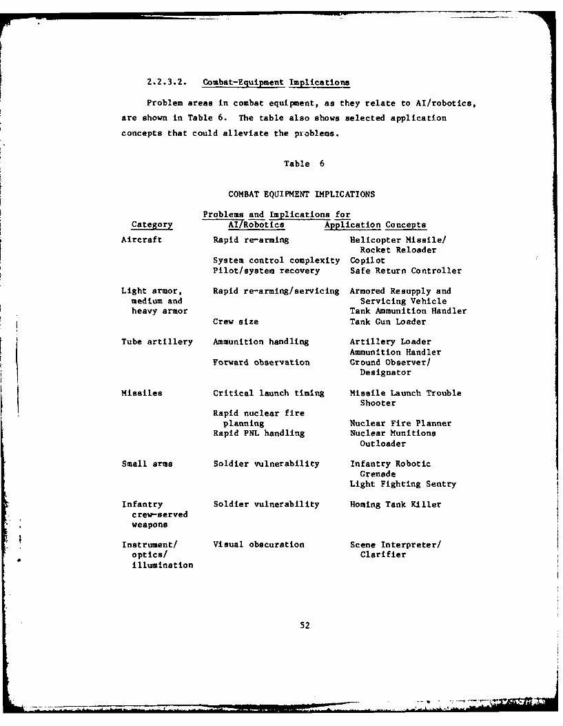
2*2.3.2. Combat-Equipment Implications
Problem areas in combat equipment, as they relate to Al/robotics,
are shown in Table 6. The table also shows selected application
concepts that could alleviate the problems.
Table 6
COMBAT EQUIPMENT IMPLICATIONS
Problems and Implications forCategory AI/Robotics Application Concepts
Aircraft Rapid re-arming Helicopter Missile/Rocket Reloader
System control complexity Copilot
Pilot/system recovery Safe Return Controller
Light armor, Rapid re-arming/servicing Armored Resupply andmedium and Servicing Vehicleheavy armor Tank Ammunition Handler
Crew size Tank Gun Loader
Tube artillery Ammunition handling Artillery Loader
Ammunition HandlerForward observation Ground Observer/
Designator
Missiles Critical launch timing Missile Launch TroubleShooter
Rapid nuclear fire
planning Nuclear Fire PlannerRapid PNL handling Nuclear Munitions
Outloader
Small arms Soldier vulnerability Infantry RoboticGrenade
Light Fighting Sentry
Infantry Soldier vulnerability Homing Tank Killerc rev-servedweapons
Instrument/ Visual obscuration Scene Interpreter/optics/ ClarifierIllumination
52
- -- am~

Within the category Aircraft, three concepts were identified that
address themselves to the inherent complexity of helicopter operations.
The Helicopter Missile/Rocket Reloader would be a robotic system for
servicing attack helicopters at forward rearming points. It would offer
the advantages of speed and armor protection for ground support
personnel as opposed to present-day exposed, human-labor-intensive
systems. (Similar systems could be conceived for refueling.) The
system would increase aircraft mission availability. Copilot would be
an artificial intelligence system that would perform the functions of
the copilot in attack helicopters. This concept would save spaces,
training time, and the weight of a two-versus-one-man aircraft. It is
expected that improvements in both aircraft and mission performance
would result. Safe Return Controller would be an on-board artificial
intelligence system that, upon sensing pilot dysfunction, would assume
flight control, including returning the aircraft to a safe landing.
Among the Armor category concepts, the Armored Resupply/Service
Vehicle incorporates several robotic applications that would allow
rearming, refueling, and minor repair in conventional as well as NBC
battlefield environments. The concept could speed complete servicing
and rearming of tanks and, thus, increase their availability for combat.
The Tank Ammunti- Handler would be a system to speed the process of
rearming tanks in forward areas. It would perform all the functions of
moving the round from its transporter directly into the storage
compartment in the tank. It would be a less complex, shorter-range
concept than the Armored Resupply Service Vehicle, but it could also
contribute to reducing rearming time. The Tank Gun Loader would be an
automatic loader that would select and move the rounds from the storage
compartment into the gun. It could allow elimination of the loader from
the tank crew.
Within the category tube artillery, problems exist in ammunition
handling that are somewhat similar to those in tanks. The Artillery
Loader would be a robotic device that would select, lift, remove the
lifting plug, fuze the projectile and present it into the breech of the
53
... .. ....... ...

gun/howitzer. Such a system would save several manpower spaces per tube
artillery crew, and would be capable of continuous operation and rapid
displacement as necessary. The Ammunition Handler, by comparison, is a
robotic device that is used to load ammunition carriers at the forward-
area ammunition-resupply points. The Ground Observer/Designator concept
would provide for the robotic functions of a forward observer while
incorporating the capability to illuminate a target with a laser for
engagement by indirect or direct fire weapons. The benefits of such a
system would include savings in spaces, and substitution for soldiers in
a hazardous task.
Within the 'missile' category, the Missile Launch Trouble Shooter
would address itself to the problem of critical launch timing. This
artificial-intelligence-based system would provide on-site, interactive
diagnosis and corrective maintenance information for surface-to-surface
missile launching systems beyond the capability of automet'. test
equipment to handle unusual problems. It, thus, would act as an
advisor/prompter/consultant to the crew. Such a system could increase
system mission performance, by allowing the crew to recover from unusual
failure or fault situations during the launch sequence. The Nuclear
Fire Planner, an artificial-intelligence-based system, would perform
rapid and accurate assessments of related tactical data in preparation
for fire missions. It would be integrated with other target
information, acquisition and fire-control systems, thereby performing
many of the detailed and time-consuming planning functions and data-
processing tasks otherwise done by humans. The Nuclear Munitions
Outloader robotic concept could speed the outload of PNL from storage
sites when such action was ordered.
Consideration of the 'small arms' category leads primarily to
concepts that address problems of soldier vulnerability by man-extension
techniques. The Infantry Robotic Grenade would be a self-propelled,
programmable ordnance item capable of self-navigation to a target, which
might include personnel positions, obstacles or heavy equipment. It
would have designed features that would preclude its use by the enemy or
54
_7

reverse of direction once underway. Such a device would serve to
minimize the exposure of soldiers in close offensive combat situations,
particularly against fortified positions. The Light Fighting Sentry,
likewise a robotic concept, would be both man-extending and force-
multiplying and modular in design. This robot would be capable of
performing sentry functions including delivering small arms fire on
enemy targets. Sentries plus their human counterparts would be task-
organized for particular offensive or defensive missions. (Other
derivatives of Sentry could incorporate heavier direct fire weapons, all
weather, surveillance, and EW capabilities. These concepts could
increase the effectiveness of units, possibly reduce the spaces
necessary to achieve this effectiveness, and reduce the vulnerability of
the individual soldier, while providing for continuous combat
operations.)
Within the category of 'infanitry crew-served weapons,' the Homing
Tank Killer would be an expendable, smart, robot that could be employed
by individual soldiers. The device might well be like the Infantry
Robotic Grenade, but with longer range and capable of seeking armored
targets through its self-contained homing sensor capabilities. The
system could reduce exposure of crew members to counterfire and reduce
manning spaces for existing anti-tank systems. The Heavy FightingSentry, a sentry derivative, would be capable of direct fire against
ground vehicle targets. Either light or armored vehicle-mounted, it
would be used in conjunction with other sentries and/or man-machine
systems to acquire targets and distribute fire. Again, this is an
example of a modular robotic concept that would serve as a force-
multiplier and reduce man-machine system vulnerability.
The category of 'Instruments, optics and illuminations Isuggests
concepts that have broad application among the entire set of equipment
categories since such systems address themselves to "seeing," whether it
be for observation by a single soldier or target acquisition by a weapon
system. Further, incorporating such human qualities as the ability to
discern discretely among objects in a scene would increase the
55

intelligence and autonomy of these systems. It then follows that the
requirement for a continuous human interface could be reduced to an
exception basis. Such a system, the Scene Interpreter/Clarifier, would
address the perennial problem of seeing, discerning and interpreting
battlefield information, day and night, and in all weather conditions.
The purpose of this system would be to aid the soldier during periods of
both normal and impaired visibility in the identification of battlefield
images or objects. It would be a module that could be attached to, or
used in conjunction with, such inventory items as imaging devices. The
Scene Interpreter/Clarifier would be able to discern an object or image
when it was partially obscured or camouflaged. The soldier would be
able to isolate a field in which he wanted to have an image identified,
and the module would alert the soldier to potential hazards/impending
lethality if present in that field. (An alternate version could discern
among the images identified based on its knowledge base and communicate
to other systems [weapon, intelligence] what it "sees." Operating in an
autonomous mode, it might serve as a "super" target acquisition device
in a target-rich environment for other robotic weapons systems.) This
concept would reduce the vulnerability of the individual soldier and
mitigate the problems of battlefield obscuration.
2.2.3.3. Combat-Support Equipment Implications
Problem areas in combat-support equipment, as they relate to
AT/robotics are shown in Table 7. The table also shows selected
application concepts that could alleviate the problems.
56

Table 7
COMBAT-SUPPORT EQUIPMENT IMPLICATIONS
Problems and Implications
Category for AI/Robotics Concept Examples
Light vehicles Soldier vulnerability Combat Porter
Light boats and Soldier vulnerability Semi-Autonomous Assaultequipment Raft
Current/bank effects River Reconnaissance System
Vehicle bridges Soldier workload Soldier's Slaveand ferries
Armored POL/ Rapid servicing Refuelerammunition Armor Resupply/Servicingtransport Vehicle
Communications- Antenna erection CP Antennae-Remoting Systemelectronics Relay requirements Remote Communications Relaydevices Adaptive Airborne Communi-
cations Relay
Network monitoring/ Signal Array Plannermanagement Communications Network
ManagerEW vulnerability Adaptive EW Control System
Within the first category, 'light vehicles,' the robotic concept
Combat Porter is directed at reducing soldier vulnerability and saving
human labor. This concept, a human-directed robot, would perform such
basic tasks as lifting heavy objects, transporting them to a designated
place, unloading them, and returning to the point of origin.
In the 'light boats and equipment' category, the Semi-Autonomous
Assault Raft would afford both passenger protection and semi-autonomous
operation over wet gap crossings. It would be used in conjunction with
the River Reconnaissance System, which is also a robotic device. The
River Reconnaissance System would first reconnoiter the water obstacle
and provide information about the bottom, water conditions, bank slopes,
egress soil condition and presence of mines. These concepts would
57

contribute to the reduction of hazards to personnel associated with
these types of operations.
The category of 'vehicle bridges and ferries,' suggests concepts
such as the robotic Soldier's Slave. The Soldier's Slave would assist
in the heavy lifting and moving such as those construction tasks
associated with bridge erection, as well as preparation of the routes of
egress and ingress to the crossing point(s). This concept specifically
addresses the problem of reducing the soldier's workload and possibly
saving spaces.
Within the category of 'armored POL and ammunition transport,- the
Refueler is a robotic device that would be used in conjunction with
conventional bulk POL delivery systems. It would locate fuel filling
points on small and light vehicles and dispense fuel remotely, thus
minimizing the exposure of personnel to the hazards of the operating
environment and speeding operations. The Armor Resupply/Servicing
Vehicle discussed in Section 2.2.3.2 also is suggested by consideration
of this category of equipment.
The 'communications-electronics devices' category presents a mix of
problems and concepts. The CP Antenna-Remoting System would transport
and erect radio antennas,, thereby saving labor and diverting the
inherent electronic signatures away from the command post. The Remote
Communications Relay concept would be a radio relay device capable of
autonomous land navigation to the point of employment, where it would
automatically, or on command, erect its antenna and function as a relay
station (an air- delivered version of this concept is also possible).
The Adaptive Airborne Communications Relay would be an airborne system
to perform radio relay functions. It would be mounted in a remotely-
* piloted vehicle or an unmanned autonomous aircraft platform capable of
* recognizing and acting on propagation medium changes, electronic
countermeasures and line-of-sight restrictions. The Network Manager, a
communications system artificial intelligence concept, would perform
network management functions such as routing, connectivity assessment,
user authentication and overall system control. It would save labor and
58

provide for continuous, error-free operation as opposed to current
methods. The Signal Array Planner, another AI-based system, would plan
the optimum connectivity of the network, while the Adaptive EW Control
System would involve the use of sensors to intercept, locate and
identify the enemy in support of EW plans and operations. Once
interception was accomplished, it would assist in making the decision to
continue the intercept, jam, deceive, destroy, or reassess the
situation. These systems, integrated and working together, would
provide for a significant increase in command, control, and
communications effectiveness while contributing to the mitigation of
vulnerability.
2.2.4. Functions
An alternative viewpoint for identifying useful Al/robotics
applications is the examination of the functions associated with the
combat and combat-support system of the Army. The Army has defined
eight broad functional areas, which provide a useful basis for the
examination. These provide the current partitioning of Army activities
for addressing Army problems and needs via Mission Area Analyses. In
this section, these functions and their subfunctions are considered and
pertinent AI/robotics concepts derived.
2.2.4.1. Functional Areas
The eight broad functional areas defined by the Army are as
follows:
* Close combat
* Fire support
* Air defense
* Command and control
* Communications
* Intelligence and electronic warfare
* Combat support, engineering, and mine warfare
* Combat service support
59

The combat service support function was not considered in this analysis.
The other functions can be aggregated into combat and combat-support
categories as follows:
* Combat Functions
(1) Close combat
(2) Fire support
(3) Air defense
* Combat -Support Functions
(1) Combat support, engineering, and mine warfare
(2) Command and control
(3) Communications
(4) Intelligence and electronic warfare
The combat and combat support functions have been further expanded to
highlight some of the associated subfunctions. These are listed in
Table 8.
60

Table 8
COMBAT AND COMBAT SUPPORT FUNCTIONS AND SUBFUNCTIONS
Category Function Subfunction
Combat Close combat Direct fire (individual)ManeuverDefend
Fire support Indirect fireDirect fire (crew)
Air defense Antiaircraft fire
Combat Combat support, Construction, bridges, barrierssupport engineering, and Obstacle breaching/avoiding
mine warfare
Command and control Data processingSituation assessmentPlanningCoordination
Communications Transmit and receiveCOMSECVoice and data
Intelligence and EW Enemy informationReconnaissanceEW
The identification of subfunctions provides a means to assist in
the orderly identification of associated problems that may have
AI/robotics implications.
In the following sections, an official definition of each
functional area is followed by a brief discussion introducing the
selected concept examples. A more complete description of the selected
concepts can be found in Appendix A.
The identified problems that flow from the combat and combat-
support functions and subfunctions shown in Table 9 through 17 tend to
suggest long-range research and development issues. They are helpful in
focusing on Al/robotics implications. The problems, which will be
ultimately identified in the Army's Mission Area Analyses (MAA) of these
functions, would certainly be important in identifying potential
61

applications, but further analysis may indicate that they may have a
rather short-term focus. A leap in Al/robotics technology may obviate
the necessity for dealing with these shorter-term issues. In any case,
since most of the MAAs were not available, they have not been used as a
basis for this functional analysis.
2.2.4.2. Close Combat
Close combat addresses those efforts directly related to the
direction and generation of combat power by light, medium, and heavy
forces for the purpose of destroying enemy forces in the direct fire
battle. Close combat includes the employment of support weapons organic
to maneuver forces as well as close air support, attack helicopters, and
directed energy weapons. Included are maneuver, target acquisition,
battle control, target processing, target attack, and target-attack
assessment. Implied is the requirement to secure and hold terrain when
necessary.
Close combat implies direct "eyeball to eyeball" contact with the
enemy. As indicated in Table 9, close combat with the enemy could come
about in a number of ways including direct fire, maneuver, and defense.
The principal threat to the soldier in the conduct of close combat is
being engaged by the enemy. This results from being observed and then
being fired upon by a direct-fire weapon.
The implications for Al/robotics derive from the direct-fire
situation and the solution lies in countering the enemy's observation
and fire. This is accomplished by maneuvering while at the same time
maintaining accurate orientation (position location), by providing
physical and NBC protection for the soldier, and finally, by building
barriers as situations permit to keep the enemy at a distance, or slow
his advance.
Some application concepts that substitute a robotics device for a
soldier in a direct-fire situation are indicated. In each case, the
robotic device assumes the position and function of a soldier engaged in
close combat. Because of the robot's design characteristics, it not
62
III PO"iii~ l iiiiiiiiiiiilliiiiiI Ot u -
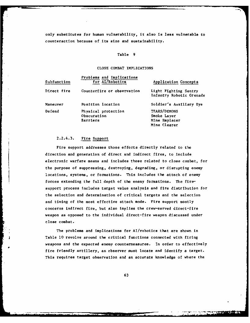
only substitutes for human vulnerability, it also is less vulnerable to
counteraction because of its size and sustainability.
Table 9
CLOSE COMBAT IMPLICATIONS
Problems and Implications
Subfunction for AI/Robotics Application Concepts
Direct fire Counterfire or observation Light Fighting SentryInfantry Robotic Grenade
Maneuver Position location Soldier's Auxiliary Eye
Defend Physical protection TEARS/DEMONSObscuration Smoke Layer
Barriers Mine EmplacerMine Clearer
2.2.4.3. Fire Support
Fire support addresses those efforts directly related to the
direction and generation of direct and indirect fires, to include
electronic warfare means and includes those related to close combat, for
the purpose of suppressing, destroying, degrading, or disrupting enemy
locations, systems, or formations. This includes the attack of enemy
forces extending the full depth of the enemy formations. The fire-
support process includes target value analysis and fire distribution for
the selection and determination of critical targets and the selection
and timing of the most effective attack mode. Fire support mostly
concerns indirect fire, but also implies the crew-served direct-fire
weapon as opposed to the individual direct-fire weapon discussed under
close combat.
The problems and implications for Al/robotics that are shown in
Table 10 revolve around the critical functions connected with firing
weapons and the expected enemy countermeasures. In order to effectively
fire friendly artillery, an observer must locate and identify a target.
This requires target observation and an accurate knowledge of where the
63

target, friendly artillery, and observation position are located. The
potential target must be identified as friend or foe. Consideration
must also be given to denying the enemy knowledge about our own forces
to preclude him from effective use of his own fire support. His
K knowledge of our firing positions will cause counterfire. In addition,
he can target our communications in order to destroy a friendly command
post. And, finally, even without pinpoint accuracy, he can target a
general suspected area with NBC weapons.
Table 1.0
FIRE SUPPORT IMPLICATIONS
Problems and ImplicationsSubfunctions. for Al/Robotics Application Concepts
Indirect fire Target observation Ground Observer/DesignatorAerial Observer/
DesignatorTarget identification 1FF ModulePosition location Super SextantNBC protection NBC SentryCommunications Remote Communications Relay
Direct fire Crew vulnerability Heavy Fighting Sentry
2,2.4.4. Air Defense
Air defense encompasses those efforts directly related to
destroying, disrupting, or degrading the effectiveness of enemy air-
breathing systems, tactical missile systems, and satellites used for
reconnaissance or attack of friendly facilities, personnel, and systems.
Included are aircraft, missiles, munitions, and target acquisition means
integral to the air defense system.
Air defense implications and concepts are shown in Table 11. The
air defense function concerns itself with the rapid identification and
destruction of enemy aircraft. A major problem for AT/robotics is in
the identification friend or foe (1FF) of aircraft. If friendly, they
must not be engaged, and if foe, they must be destroyed before they
64

engage friendly ground targets. This IFF problem pervades many
potential Al/robotic weapon systems. An IFF Module addressing this
problem would be an AI system that can rapidly recognize discrete
aircraft signatures, thereby permitting engagement and destruction of
enemy aircraft, while at the same time precluding engagement of friendly
aircraft.
Table 11
AIR DEFENSE IMPLICATIONS
Problems and ImplicationsSubfunctions for AI/Robotics Application Concepts
Antiaircraft fire IFF IFF ModuleEngagement Close Air-Defense Sentry
2.2.4.5. Command and Control
This function encompasses the capabilities required by a commander
to review and analyze information, assess the situation, and to direct,
manage, and control forces during operations in the accomplishment of
his mission. Included is the iterative process of monitoring the enemy
and friendly situation, planning, and replanning, estimating, deciding,
providing for operations security and selecting and directing the
correct option based on the overall scheme. Information systems and
those systems required for controlling and releasing nuclear and
chemical weapons are integral to this function.
Command and control implications and concepts are shown in
Table 12. Command and control conducted by Army leaders relies on
accurate and timely information on many factors that affect the outcome
of the battle. Although great strides have been made in providing
information from which commanders must make decisions, little has been
done to uncomplicate the process or to crystallize that information
which is vital to mission success. It is in solution of these problems
that AI has tremendous potential. Many useful applications are within
65

the potential solution realm of Al. Examples are: the ability to cull,Lstore, recall details on the enemy weather and terrain; the ability to
route messages, select frequencies and automatically adjust to the
effects of enemy actions; the ability to do detailed complex NBC
planning; and the ability to keep track of a constantly changing
situation.
The capability of a commander to use his voice to access data bases
[ in order to obtain updated information even in operations concept
formulation would be a great benefit.
Table 12
COMMAND AND CONTROL IMPLICATIONS
Problems and Implications ApplicationSubfunctions for Al/Robotics Concepts
Receive, process, Too much information, Multi-Sensor Dataanalyze not culled Assimilator
Assess situations Speed, currency Mission Execution Monitor
Brigade Situation Analyzer
Formulate plans, Rapid changing River Crossing Plannerissue orders situations Nuclear Fire Planner
Division Commander's QuickData Access Svscem
Coordinate forces, Rapid execution in Brigade Mission Plannerfires, support changing situations
2.2.4.6. Communications
Communications include the capability to transmit and receive
timely information flow among different echelons of the force and its
* sustaining base. Included is the capability to communicate from widely
dispersed positions in an enemy-induced electro-magnetic pulse, nuclear,
biological, chemical, or electronic warfare environment.
Communications implications and concepts are shown in Table 13.
Two aspects of "communications" appear to be particularly attractive
66

candidates for Al/robotics technology. The ability to remotely
reposition communications system equipment (antennas, transmitters,
generators, etc.) or to remotely reset or replace damaged equipment
would permit the operation in a hostile environment. In addition, by
remote movement of signature emitting communications elements, the
location of important command and control nodes can be disguised.
Table 13
COMMUNICATIONS IMPLICATIONS
Problems and Implications ApplicationSubfunctions for A17Robotics Concepts
Transmit and Rapid antenna erection CP Antenna-Remoting Systemreceive Transmission over Remote Communications Relay
hostile territory
COMSEC Intercept capabilities Adaptive AirborneCommunications Relay
Voice and data Network optimization Communication Network Manager
2.2.4.7. Intelligence and Electronic Warfare
Intelligence and EW addresses the capability to determine type,
characteristics, disposition, movement, and intention of enemy units as
a support to battlefield management and the acquisition of targets. It
includes the exploitation of reconnaissance information gained by close
combat forces in addition to the employment of ground and air
reconnaissance systems to collect information. Additionally, it
includes the means to analyze, correlate, and integrate information to
form usable intelligence and to disseminate that intelligence. The
intelligence system is netted with the various firepower target
acquisition systems. Electronic warfare includes the capability to
detect, identify, locate, report, disrupt, destroy, deceive, and exploit
enemy electromagnetic systems and includes those efforts taken to
protect friendly electromagnetic systems.
67

Intelligence and EW implications and concepts are shown in
Table 14. Intelligence must be timely and accurate in order to be of
maximum benefit to a commander. Getting to crucial information and
drawing accurate conclusions is within the range of AI technology.
Table 14
INTELLIGENCE AND EW IMPLICATIONS
Problems and Implications ApplicationSubfunctions for AlURobotics Concepts
Enemy information Fusion Tactical Threat
Projection System
Rapid collection Interrogation Support
System
Reconnaissance Accuracy, change, NBC Reconnaissance Robotspeed hazards Tactical Reconnaissance
Robot
EW Headquarters signatures CP Antenna-RemotingResponsive System
countermeasures EW Sentry
2.2.4.8. Combat Support, Engineering, and Mine Warfare
This function addresses those efforts related to combat engineering
operations and mine/countermine warfare. It encompasses the tasks of
mobility, countermobility, and survivability. It includes position
fortification, NBC hardening, and the emplacement/breaching of barriers
and obstacles. Included is planning for the employment of families of
mines, base/road construction and maintenance, bridging and power
generation.
Implications and concepts are shown in Table 15. This function has
several aspects that lend themselves to being addressed by Al/robotics
technology. In general, these engineering type activities involve heavy
equipment, operations in hostile environm-nt, intensive labor, adverse
68
* - -.

terrain, and danger from enemy action. The application concepts deal
with one or more of these aspects. The fact that the River
Reconnaissance System, for instance, could perform certain functions in
the immediate combat area, would not preclude its optimal operation in
rear area situations. In both instances, it would replace a time-
consuming, dangerous human endeavor.
Table 15
COMBAT SUPPORT, ENGINEERING, MINE WARFARE IMPLICATIONS
Problems and Implications Application
Subfunctions for At/Robotics Concepts
Construction/bridge Exposure to fire River Reconnaissancebuilding/barriers System
Danger of detonation Barrier Emplacement Aid
Speed of emplacement Mine Emplacer
Obstacle breaching/ Speed and secrecy, Engineer Reconnaissanceavoiding terrain variables, Robot
marking Mine Clearer
2.2.5. Environment
Consideration of the implication of the battlefield environment for
Al/robotics Lnvolves two distinct aspects. As in the other analyses,
environmental factors in themselves can suggest potentially useful
Al/robotic concepts. In addition, it must be recognized that
Al/robotics is an emerging technology, which, to this date, has not
included development of systems for operation in the battlefield
environment. That environment implies several needs that must be
accounted for in any development program that is intended to produce
actual fielded systems. Both of these aspects are discussed in this
section.
69

2.2.5.1. Environmental Implications and Application Concepts
Five major environmental factors were considered in this analysis.
They are:
* Terrain
* Climate
* Visibility
* Obstacles
* NBC Contamination
Each of the environmental factors involves problem areas and potentially
useful Al/robotics concepts. These are summarized in Table 16.
Variations in elevation and vegetation are terrain factors that
frequently limit the line of sight. This, in turn, limits employment of
weapons, and the use of line-of-sight communication systems, which have
natural advantages against EW threats. The Aerial Observer/Designator
and the Adaptive Airborne Communications Relay are concepts that could
alleviate these problems.
70

Table 16
ENVIRONMENT IMPLICATIONS
Problems andEnvironmental Implications for Application
Factors Al/Robotics Concepts
Terrain Line-of-sight limitations Aerial Observer/Designator
Rough terrain traffica- Adaptive Airbornebility Communications
Relay
Climate High/low temperature Soldier's Slavework degradation
Arid area water Water Findersources
Visibility Multi-sensor integration Multi-Sensor Data(fog, smoke, haze) Assimilator
Obscure scenes Scene Interpreter/Clarifier
Water obstacles Support hasty crossing River ReconnaissanceSystem
Semi-AutonomousAssault Raft
NBC contamination Rapid, safe reconnaiss- NBC Reconnaissanceance Robot
Rapid decontamination Vehicle DecontaminatorMOPP/soldier labor Soldier's Slave
The Army must be prepared to operate in areas with widely varying
climatic conditions. The degradation of soldier performance in extreme
high or low temperature conditions can reduce effectiveness of forces
drastically. The Soldier's Slave would be able to perform a wide
variety of heavy work tasks under such extreme conditions. In some
areas, such as the Middle East, the overall arid climate severely limits
the availpbility of water. Water is critical to the soldier--and to
some of his equipment. In such areas, limited sources of water are
available from sources that would not normally be recognized. An expert
71

system to advise soldiers attempting to find water could alleviate this
problem.
Battlefield visibility is frequently obscured due to natural or
manr-made causes. Fog, haze, and dust are often present. Man-made
obscurants can effectively limit visibility across a %wide spectrum
including the infrared and ultraviolet. As a consequence, many types of
sensors are used in today's Army, and this diversity is increasing.
Integrating and interpreting data from multiple sensors is an area in
which Al approaches offer potential benefits. (In fact, this is an area
to which AI research has already been directed.) In combination with
vegetation, minor visibility impairments can cause a complex visual
scene, in which it is extremely difficult for the soldier to detect, and
identify objects of interest. The Scene Interpreter/Clarifier could aid
the soldier in this area.
Water obstacles ranging from small streams to large lakes present
significant impediments to the maneuver of ground units. River crossing
operations are particularly complex, difficult and hazardous for Army
combat units. The rapidly moving, widely dispersed unit battlefield
conditions visualized in the Air-Land Battle 2000 study suggest that
isolated units will be forced to conduct hasty crossings, without the
extensive preparation and support associated with deliberate crossing
operations. Two concepts could assist in this area: the River
Reconnaissance System, to perform rapid water reconnaissance, and the
Semi-Autonomous Assault Raft.
The capabilities of the Soviet Union to employ chemical and nuc'ear
weapons on the battlefield are well recognized. In addition to their
immediate destructive effects, these weapons can create extensive areas
of contamination. In order to avoid casualties, Army units must either
avoid such areas, or adopt protective measures that seriously degrade
performance. The mission-oriented protective postures (MOPP) vary for
different situations, but, in all cases, operations are impaired. The
soldier wearing full protective equipment simply cannot perform heavy
work for a long period of time. The Soldier's Slave could greatly aid
72
____________- - ---..........

in this area, and could also reduce the hazards to soldiers associated
with leaving protected environments such as vans or CP shelters. Rapid
reconnaissance is necessary If contaminated areas are to be avoided.
The N"BC Reconnaissance Robot could fill this need. Finally, combat
equipment such as tanks must be rapidly decontaminated after exposure to
chemical attack or contamination. The present slow, hazardous methods
of performing such decontamination operations could be greatly improved
by a Robotic Vehicle Decontaminator.
2.2.5.2. Environmental Design Requirements
Military equipment must be designed to withstand many environmental
extremes and to operate in the field under adverse conditions. It is
quite obvious that systems designed for use in a factory environment
would not be suitable for the military environment. It is less obvious
that development of technical approaches that produce the best robot for
use in a benign environment may not be the best approaches, or even
suitable approaches, for devices intended to operate in a military
environment. The need to meet environmental requirements must be
recognized early in the R&D process--not deferred with the expectation
that band-aid approaches can solve these problems after the basic
development work is completed. Four general areas are of particular
concern. They are:
" Day/Night/All-Weather.Operations--System designs must notanticipate operation under well lit, dry conditions andmoderate temperature domains.
" Conventional and NBC Hardening--In addition to the obviousneeds for some degree of protection from normal weaponeffects, two aspects of hardening bear particularattention. Electrical and electronic systems are highlyvulnerable to the electromagnetic pulses associated withnuclear weapon bursts. Approaches that provide goodprotection against such effects are available. Manymaterials commonly used in the fabrication of equipment are
* not compatible with chemical agents and decontaminants.
" Environmental Engineering -Systems must be able towithstand factors such as vibration, shock, humlidity, dust,and storage in extreme temperatures.
73

* Reliability-Availability-Maintainability (RAM)--The normal
military requirements for RAM are far beyond the demands ofmost factory applications. Approaches that are suitablefor the factory may be inherently unsuitable for meetingthese requirements.
The essential point to be made is that the rapid emergence of this
technology suggests that exploratory development efforts specifically
focused on solving environmental problems as they pertain to AI/robotics
are needed, not that AI/robotics systems cannot be fielded for a
military environment. Lack of such early programs may cause eventual
severe delays or setbacks in Army efforts to field applications for
combat and combat support.
2.2.6. Personnel
In the course of all of the analyses discussed in the preceding
sections, it repeatedly appeared that many of the problem areas and
potential applications were influenced by manpower and personnel
considerations. In the numerous discussions of problems and potential
applications with Army agencies, which occurred during the study,
manpower and personnel issues also were frequently raised.
These manpower and personnel problems suggest four major ways in
which AT/robotics could contribute to solving manpower and personnel
problems, These areas of contribution can be viewed as personnel
thrusts for Al/robotics. They are:
* Hazardous Situations--Assist the soldier in performing
required tasks in hazardous situations.
* Augment Manpower--Multiply the combat power contribution of
soldiers by augmenting their roles in combat and combatsupport. Ultimately, this may involve replacing soldiers
in some tasks.
* Enhance Capabilities--Enhance the soldier's ability to
Jperform difficult or complex tasks.
* Simplify Interfaces--Simplify the soldier-machine interface
involved in high technology systems.
Each of these personnel thrusts implies more detailed problems and
potential AT/robotics concepts. These are shown in Table 17.
74

Table 17
PERSONNEL THRUST IMPLICATIONS
Problems andImplications ApplicationPersonnel Thrusts for AI/Robotics Cnet
Hazardous situations Avoid direct and Infantry Robotic Grenadeindirect fire Homing Tank Killer
Infantry PrecursorStreet Walker ScoutSoldiers Auxiliary Eye
NBC survival NBC SentryVehicle DecontaminationContaminated Casualty Handler
Augment manpower Multiply soldier TEARS/DEMONScombat power Light Fighting Sentry
Heavy Fighting Sentry
Perform support Mine Emplacertasks Smoke Layer
Cargo Handler
Enhance capability Heavy or tedious Soldier's Slavetasks Ammunition Handler
Complex tasks ASP Layout PlannerSoldier's Movement GuideEmergency Repair and
Maintenance Advisor
Simplify interface Speech control Speech Command AuditoryDisplay System
Voice Helicopter ControlSystem
Computer access Division CommandersQuick Data-Access System
The primary hazards facing the individual soldier on the
battlefield are direct and indirect fire weapons and NBC hazards. The
concepts listed in Table 17 would all contribute to allowing the soldier
F to perform combat and combat-support tasks with a reduced exposure to
these hazards.
75

Currently, the Army must maintain combat-ready forces under severe
limitations on available manpower. In war-time, it is generally
anticipated that the Soviet Union can deploy numerically superior
forces. There is no reason to believe this situation will improve
significantly in the future. Thus, it is important to augment the
available manpower as much as possible to perform combat and combat-
support tasks. This may take the form of placing one or more semi-
autonomlous systems under the control of a soldier, or in the longer
term, replacing soldiers in certain tasks. The application concepts
shown in Table 17 could contribute in this area.
Many tasks on the battlefield require heavy or tedious work. In
many cases, such tasks amount to simple labor. The Soldier's Slave and
the Ammunition Handler illustrate Al/robotic approaches to performing
such tasks. Other tasks are highly complex. They demand extensive
training, a high degree of intellectual ability, or an extensive
background of experience. AI/robotics systems, as illustrated by the
concepts shown in Table 17 could aid in this thrust--allowing soldiers
with modest skills to perform complex tasks in a satisfactory manner.
The soldier-machine interface involves the understanding,
operation, maintenance, repair, and control of equipment and the othert resources of warfare, often under severe time constraints in very
hazardous environments. As this interface becomes more sophisticated
technologically, and the lethality of the battlefield increases
accordingly, machines place an increasing demand on the individual
soldier's presence of mind, intelligence, dexterity, stamina, and
overall professional acumen.
Simplifying the interface between soldiers and machines can allow
the soldier to concentrate his abilities on the elements of tasks for
which humans are best suited, without requiring complex and time
consuming interaction with equipment involved. The basic thrust is to
allow soldiers to control machines or communicate with machines with a
minimum of manual and intellectual effort devoted to the specifics of
control and communication. The application concepts shown in Table 17
76
-raw

illustrate some ways in which AT/robotics can contribute to this
process.
2.3. Summary
As a result of the analyses described in Section 2.2, and extensive
discussion with Army agencies as described in Section 2.1, 100 concepts
for C/CS applications of AI/robotics were developed. The concepts are
listed in Table 18 and briefly described in Appendix A. The order in
which they are listed is the same in Table 18 and Appendix A. The basis
for the order is explained in Section 4.1, Application Categories. Ten
concepts selected as category examples are explained in detail in
Section 4.2, Category Examples.
As listed, the concepts represent a synthesis of many more ideas,
which varied somewhat in minor features, primary purpose, or degree of
technological advancement. In some cases, they are closely akin to
concepts that have been previously studied or are planned for study in
the near future. In other cases, they represent new ideas. The
concepts have been deliberately formulated in a manner consistent with
feasible technology advances, rather than within the current state of
the art. In most cases, it would be possible to pursue much less
sophisticated versions of the concepts in the near future.
77
V-7-7"

Table 18
AI/ROBOTICS APPLICATION CONCEPTS
Human/Equipment Interface AidsSpeech Command Auditory Display SystemVoice Helicopter Control SystemScene Interpreter/ClarifierMulti-Lingual Order GeneratorDivision Commander's Quick Data-Access System
Planning and Monitoring AidsMission Execution MonitorSignal Array PlannerWeapon Selection PlannerMissile Launch Planner/ControllerRiver-Crossing PlannerCovering Force Maneuver PlannerASP Layout PlannerBrigade Mission Planning AidSoldier's Movement GuideNuclear Fire Planner
Expert AdvisorsEmergency Repair and Maintenance AdvisorMissile Launch Trouble ShooterCombat Vehicle Service and Survival AdvisorEOD AdvisorWater Finder
Data Assimilation and Access AidsInterrogation Support SystemC2 Database Query LanguageRoute Planning AidCombat Vehicle C
2
Imagery Interpretation AidAdaptive Database Reconfiguration SystemMulti-Sensor Data Assimilator
Handling Support SystemsArtillery LoaderTank Ammunition HandlerTank Gun Loader
Contaminated Clothing HnadlerContaminated Casualty Handler
Cargo HandlerMulti-Purpose ManipulatorRefuelerVehicle Recovery Aid
Ammunition HandlerHelicopter Missile/Rocket ReloaderNuclear Munition Outloader
Support SystemsVehicle Decontaminator
78

Armor Resupply and Service VehicleLine Charge LayerSemi-Autonomous Assault RaftAir Robotic PlatformGround Rootic Platform
Combat Vehicle--Support SlaveCombat PorterMine EmplacerSoldier's SlaveReconnaissance Robot
Remote Communication Relay
Adaptive Airborne Communication RelaySmoke LayerInfantry PrecursorArmor PrecursorCP Antenna Remoting SystemMan-Packed Portable Deception System
EOD AssistantAirborne Minefield Detection SystemBarrier Emplacement AidRemote Adaptive Jamming SystemMine Clearer
Situation Assessment SystemBrigade Situation AnalyzerArtillery Movement Assessment SystemTactical Threat Projection SystemSuper SextantChemical Hazard Warning AnalyzerDeceptive Identification System
System ControllersLine-of-Sight ControllerSafe Return ControllerFire Allocation and Control SystemIFF Module
CopilotArmor Hit Avoidance SystemHelicopter Automatic Target Acquisition System
EW Equipment ControllerCommunication Network ManagerAdaptive EW Control SystemTarget Acquisition and Homing DeviceTarget Acquisition/Allocation System
WeaponsTears/DemonsLight Fighting SentryHeavy Fighting SentryClose Air Defense SentryHoming Tank Killer
Information CollectorsRiver Reconnaissance SystemNBC Reconnaissance RobotAerial Observer/Designator
79

Ground Observer/DesignatorRemote Scene AnalyzerEW SentryNBC Sentry
Wire TapperStreet Walker ScoutApproach SentryLeach Armor MarkerMulti-Purpose Sensor EmplacerTactical Reconnaissance RobotSoldier's Auxiliary Eye
It should be recognized that the development of these concepts
involved only enough effort to recognize that they would be useful in
terms of solving or alleviating Army problems. None of the concepts was
analyzed in sufficient depth to clearly understand whether or not the
Army should or should not pursue them in the stated form. Overall, the
concepts form a body of useful ideas, and a collection of adequate
breadth to cover the potential of AI/robotics for combat and combat
support.
In addition to specific application concepts as listed in Table 18,
the analyses led to some insights of a more general nature that should
be considered in planning AI/robotics R&D. These pertain to
militarization, evolutionary approaches, modular approaches, and
countermeasures.
Militarization involves problems of guiding emerging AI/robotics
technology from the factory to the battlefield environment. These are
discussed in some detail in Section 2.2.5.2. Exploratory development
efforts related to such areas as day/night/all-weather operation,
conventional and NBC hardening, environmental engineering and RAM are
needed to avoid serious delays or setbacks in Army efforts to field
applications.
The Army does not have any experience with fielded AI/robotics
systems to use as a guide for the many judgments involved in system
development. This suggests that an evolutionary approach should be
followed--beginning to field systems that are within the current state
of the art and using the experience gained with such systems as an
80

ingredient of future development programs. There are three specific
ways in which such evolution should occur.
* Increasing Autonomy--Systems can evolve from remote control
or very limited semi-autonomy (which is within the current
state of the art), to fully autonomous versions.
* Increasing Flexibility--Single-purpose systems can evolve
into multi-purpose systems.
* Increasing Distribution--Very limited production and
distribution of trial systems can precede Army-widefielding of large quantities of equipment.
Many applications require similar Al/robotics modules, such as
vision or legged locomotion. In addition, it appears that some concepts
can be structured as different versions of the same basic system. Work
toward achieving commonality of modules early in the development plan
can contribute to better and cheaper progress in the future. Some
specific areas in which such modular approaches could be pursued are:
* Basic mobile carriers
* IFF modules
* Multi-purpose expert system frameworks
* General-purpose planning support modules
* Sentries with varying armament and purpose.
Early work is needed on countermeasures as they apply to Al/robotic
applications. An understanding of both the countermeasures that any
enemy might employ, and the feasible active and passive counter-
countermeasures is a necessary ingredient for developing truly effective
systems. In addition, it is important for the U.S. to begin to
consider what countermeasures might be effective and needed against a
potentially significant Soviet Al/robotics combat threat.
81
. .... .. -,-_. .

3. ARTIFICIAL INTELLIGENCE AND ROBOTICS
3.1. Introduction
To be able to perform human tasks, an intelligent robot should be
able to think, sense, and effect (move and manipulate). The thinking of
"brain function," executed by a computer, is the domain of artificial
intelligence. Sensing and effecting are "body functions;" they are
based on physics, mechanical engineering, electrical engineering, and
computer science. Planning and execution of tasks entail both brain and
body, and so are affected by both artificial intelligence and robotics.
We will not attempt to distinguish between artificial intelligence and
robotics but will present a model that encompasses both.
There are two basic goals of the research in these areas: to make
computers smarter and to improve our understanding of human
intelligence. The latter is also sometimes called "cognitive science"
or "cognitive psychology." These two goals do not necessarily conflict,
and, in fact, many researchers work toward both. For the purposes of
this report, we will concentrate on research with the goal of making
computers smarter.
Artificial intelligence and robotics are really in their infancy,
but their promise is great. Some practical applications of this
research are appearing, although in most cases they are limited and
aimed at solving specific problems. Current research is directed
towards both extending the capabilities of current applications and
finding more general solutions to the problems they address.
In this section we will outline the current state of artificial
intelligence and robotics and the basic research issues being addressed.
We will focus on some of the problems that must be solved before certain
aspects of intelligence will be available in computers. In Section 5,
83
-'i

we will make some predictions about future capabilities, the time and
effort they will require, and the associated risks. A bibliography
organized by subject area appears in Appendix A. Individual research
will generally not be cited in this section.
Before discussing what artificial intelligence and robotics is, we
will briefly mention who is doing research in these areas and where.
3.2. Background
The number of researchers in artificial intelligence and robotics
is rapidly expanding with the increasing number of applications and
potential applications of the technology. This growth is not only in
the United States, but worldwide, particularly in Europe and Japan.
Basic research is going on primarily at universities and some
research institutes. Originally, the primary research sites were MIT,
CMU, Stanford, SRI, and the University of Edinburgh. Now, most major
universities include artificial intelligence and/or robotics in the
computer science curriculum.
An increasing number of other organizations either have or are
establishing research laboratories for artificial intelligence a,
robotics. Some of them are conducting basic research, others are
primarily interested in applications. These organizations include:
Xerox, Hewlett-Packard, Schlumberger-Fairchild, Hughes, Rand,
Perceptronics, Unilever, Philips, Toshiba, and Hamamatsu.
Also emerging are companies that are developing artificial
intelligence and/or robotics products. U.S. companies include:
Unimation, Cincinnati Milacron, MIC, Automatix, Teknowledge,
Intelligenetics, Cognitive Systems, Artificial Intelligence Corp,
Symantec, and Kestrel Institute.
84

3.3. A Unified Model for Artificial Intelligence and Robotics
Figure 2 can be viewed as a simplified model of an intelligent
system. We will use it as a model for artificial intelligence and
robotics. The major components are:
* Sensing
* Effecting
* Interpreting
* Generating
* Reasoning
WORLD MODEL
REASONING
INTERPRETING GENERATING
SENSINGEFFECTING
FIGURE 2 A UNIFIED MODEL OF ARTIFICIAL ;NTELLIGENCE AND ROBOTICS
The last three of these draw heavily on knowledge about the world and
how it works. The parts of the model should not be viewed as isolated
pieces, but rather clusters of related functions. We will describe the
model briefly here and discuss the components in more detail in the
following sections.
This model of artificial intelligence and robotics emphasizes
intelligent functions that are performed. Underlying them are more
fundamental research issues that are concerned with:
85
__ _ _ _ _ _ _ _ _ _ _ _ _ _ _ _ _,i

*Representing the knowledge needed to act intelligently
*Acquiring knowledge and explaining it effectively
*Reasoning: drawing conclusions, making inferences, makingdecisions
*Acting with knowledge that is incomplete, uncertain, andperhaps conflicting
*Evaluating and choosing among alternatives.
Advances in artificial intelligence and robotics require advances in
these fundamental areas and the capabilities of intelligent functions
(e.g., vision). In the discussion of technology gaps in Section 5 we
will include gaps in both levels: the functional level and the
fundamental level.
3.3.1. Sensing and Effecting
Sensing and effecting, the parts of the model at the bottom of in
Figure 2, are primarily dirr :ed towards interacting with the
environment. Sensing includes activities such as seeing, hearing,
touching, smelling, and measuring distance. Effecting includes moving,
object handling, and speaking. A characteristic of these actions is
that they depend on heavy interaction with the environment, but very
little (if any) ability to reason about it. They basically collect
information, or produce information or action.
Sensing covers the basic input to a system with perhaps some
limited processing that is performed independent of the use of the
information. Input can be in many forms: pictures, radar, data, speech,
typed input, and graphical input (charts, maps). This part includes
simple processing, but nothing that requires any knowledge about the
content of the input or the reasons for gathering it. For example, we
might include format tracking on a speech wave as part of sensing, but
not word identification. Similarly, some simple edge-detection methods
would fall in this area if they only work on local changes in the
digitized image and do not require information about the objects or
background.
86
Companion to sensing (input) is effecting (output), that is,
producing some signal/information or moving about. Again, some of the
topics here are concerns of artificial intelligence and robotics, others
fall under other disciplines. Under effecting we include systems that
perform with some local control, but do not 'reason' about what they are
doing. Effectors can be manipulators (hands, arms), legs, wheeled
vehicles, and various means of communication (e.g., sounds, graphics,
and pictures).
Some aspects of these areas are concerns of artificial intelligence
and robotics, others are concerns of disciplines ,.uch as physics,
mechanical engineeritig, electrical engineering, and computer science.
We will focus on topics that are concerns of robotics or artificial
intelligence.
3.3.2. Knowledge About the World
In any sophisticated interaction with its env~ronment, an
intelligent system must have some knowledge about that environment
including:
*What objects are, or could be, around, e.g., trees, rocks,lakes, rivers, people, vehicles
*Actual and possible properties of the objects, e.g., size,shape, color, texture
*Their possible relationships with other objects, e.g.,above, below, behind
*Changes that can occur and how they affect the situation,e.g., cutting down a tree destroys it; repairing a jeepmakes it usable.
As we have mentioned, questions about how to represent, acquire, and
explain this knowledge in a computer system are part of the fundamental
research in artificial intelligence and robotics.
The parts of the model we call interpreting, generating, and
reasoning all require some knowledge about the world. Furthermore, they
all use that knowledge for some purpose, such as,
*Understanding the environment, e.g., recognizing andlocating objects, and detecting changes in the environment
87

*Planning and carrying out actions to affect theenvironment, e.g., assembling objects, moving about.
3.3.3. Interpreting
Interpreting information is the means by which an intelligent
system understands its environment. The information can be acquired
through perceptual processes or other means (e.g., a database). We will
focus on interpreting images, both visual and those provided by other
sensors (e.g., radar, sonar) and interpreting language (written or
spoken).
Images are interpreted for many reasons including: detecting,
recognizing, and locating objects, detecting change (e.g., movement of
objects), and describing unknown objects. Research is directed towards
better methods for acquiring images, extracting information from the
images and using knowledge about the objects.
There are two main reasons for developing computer systems that can
interpret language: to improve a person's interaction with the machine
and to facilitate the processing of textual information by a computer.
For example, a person may interact with a computer in order to give it
commands, query various databases, or conduct a dialog with some advice-
giving system or teaching system.
Textual information may be processed in order to translate it,
summarize it, or perhaps integrate it with other information. In each
case the information must not just be 'read' but in some sense
understood'.
3.3.4. Generating
The part of the model labeled 'generating' refers to the processes
by which an intelligent system decides to influence its environment.
This effect may be through direct or indirect action. Direct actions
include manipulating objects, using hands and arms to assemble objects,
and navigating a vehicle, avoiding obstacles and possibly replanning
paths.
88

Examples of indirect actions include generating language and/or
pictures in order to convey information to a person (or another system).
The concerns of language and graphics generation are basically deciding
what to say, and how best to say it.
3.3.5. Reasoning
The ability to cope with unforeseen, incomplete, uncertain, and
perhaps conflicting information and to act and react to it is a
prerequisite of any intelligent behavior. This ability is what we have
labeled as reasoning in the final part of the model. Basic research is
directed toward discovering and developing the underlying mechanisms
necessary for reasoning.
Intelligent systems reason for many purposes, these include:
* Helping interpret sensory information
* Helping decide what effectors and sensors to use and how to
use them
* Planning actions and monitoring their execution
* Solving problems
* Gathering new information
* Diagnosing a situation
* Recognizing a situation.
In the sections on interpretation and generation, we will discuss
reasoning as it is used for interpreting and generating information. In
Section 3.8 we will discuss other uses of reasoning and the research
problems associated with developing computer systems for them.
3.4. Sensing
A wide variety of devices can be used by an Al/robotic system to
obtain information. They include not only transducers for physical
quantities, such as microphones for sounds, but data processing input
devices such as keyboards for textual information and specialized
military sensors such as NBC contaminaion detectors. In this report we
treat all these devices as different kinds of sensors.
89

For military applications there is an important distinction between
sensors that emit energy or matter (active sensors) and those that dqo
not (passive sensors). Passive sensors are preferable when stealth is
required.
The act of sensing is, in general, performed in two steps:
(1) Transducing--converting the energy, physical condition,
etc. that is to be sensed into a signal, usuallyelectrical.
(2) Preprocessing--improving the signal by noise reduction,
averaging, filtering, data compaction, and the like.
While transducing methods are usually highly specialized to one type of
external condition or Influence, preprocessing methods are often
generally applicable to signals from many different kinds of transdiicer.
3.4.1. Important Sensors for Robotics
Omitting sensors for which development is already strongly driven
by military or data-processing needs, such as radar or keyboards, the
most important types of sensors for robotics are solid-state television
cameras, range sensors, tactile sensors, and proprioceptors. The
following sections each discuss the state-of-the-art of one of these
sensors in terms of capabilities and limitations of commercially-
available equipment. They then describe advanced prototypes now in
laboratories, and extrapolate future developments. In Section 3.5 we
will discuss "interpretation" -- the problems associated with
understanding the environment from sensor information.
3.4.2. Visual Sensors
Visual sensors, using television cameras, are needed for seeing
what is around the robot. For robotic applications, solid-state cameras
are preferred over those with vacuum-tube imagers such as vidicons
because of their ruggedness, low image distortion low power
requirements, and small size.
90

Today's solid-state television cameras can operate on visible
light, or infrared. The highest image resolution available (800 by 800
pixels) is now about twice that of broadcast television, and the fastest
cameras can take 2,000 pictures per second (as compared to 30 for
broadcasting). Some imaging chips can even do simple image processing
operations themselves, such as edge enhancement.
The main limitation of present-day solid-state cameras is that
(except for one made by Hitachi) they do not take color pictures.
Another problem is that they produce information much faster than a
large conventional computer can process it, and most of it is highly
redundant and uninformative.
Laboratory prototype camera chips now do some global image
processing, such as fourier transforms. Nondestructive-readout cameras
can store an image for hours and the image can also be modified by a
computer while it is stored.
2000-by-2000-pixel resolutions should be available within about ten
years. But, to reduce the amount of image data to be processed, some
cameras may have only a small high-resolution region near the center of
their field of view ("foveal cameras").
3.4.3. Tactile Sensors
Tactile sensors either detect when the hand touches something, or
they measure some combination of force and torque components that the
hand is exerting on an object. They usually use a number of strain
gauges as transducers. However, a wide variety of simple, inexpensive
devices such as microswitches can be used if it is only necessary to
sense touch.
Force/torque sensors today use about eight strain gauges to measure
the direction and magnitude of a force up to about 50 pounds with an
accuracy of about one ounce. They can simultaneously measure the torque
in any direction with comparable accuracy.
91
-------------------------

Today's force/torque sensors are too insensitive to handle objects
lighter than a few ounces. They are also too large for use on
miniaturized robots, are rather delicate, and are expensive ($3,500-
$8,000). Commercially-available touch sensors are not especially
designed for use on robots.
Arrays of pressure sensors have been fabricated with about two
sensors per mm resolution in two dimensions.
Materials such as carbon fibers, fiber optics, and doped plastic
films may make possible large, flexible sheets of artificial "skin" with
embedded touch (or other) sensors.
3.4.4. Range Sensors
Range sensors are an important means of determining where objects
are with respect to the robot.
In-air acoustic range sensors are accurate to about one millimeter
over several meters. Laser range finders are accurate to about one
meter over a kilometer; with a retroreflector on the target, however,
they can easily measure to about a millimeter accuracy.
The main drawback to current range finders is that they must be
scanned slowly over a scene in order to determine the 3-dimensional
shape of the terrain and objects. The transverse resolution (beamwidth)
of acoustic rangers and the range resolution of laser rangers is too
coarse to be useful in many manipulation tasks.
A scanning laser ranger has been developed that simultaneously
measures the reflectance of an object as well as its distance. This
produces precisely-registered range and intensity images.
Electro-optical devices that operate in picoseconds are now being
developed. These promise to improve the resolution of laser rangers to
a few millimeters without the need for a retroreflector on the target
object.
92
3.4.5. Proprioceptors
Proprioception in robotics means sensing the posture of a
mechanical manipulator, leg, or other jointed mechanism. This is used
mainly in two ways: in controlling the mechanism whose posture is
sensed, and in sensing the posture of a teleoperator master arm in order
to command the motion of a slave arm.
Proprioception involves measuring the angle of each rotary joint
and the extension of each telescoping Joint in a mechanism. The joint
position sensors are usually either potentiometers, resolvers, or
encoders.
Today, joint position sensors are accurate enough to enable a six-
joint manipulator to place its hand anywhere within a three-meter-radius
working volume with one-millimeter accuracy.
Highly-accurate sensors for joint angles or extensions are
delicate, expensive, and difficult to manufacture. They are also too
large for use in miniaturized robots.
In future, it may prove easier to measure the position of the hand
directly than to infer it from accurate measurements of each joint
position.
3.5. Output/Effectors
As we did for sensor technology in the preceding section, we will
first list the important robotic effectors, then describe the state of
the art and extrapolate future progress for each. In Section 37 we
will discuss "generation" -- the problems associated with using these
effectors intelligently.
3.5.1. Important Effectors for Robotics
Omitting effectors for which development is already strongly driven
by military or data-processing needs, such as weapons or displays, the
most important types for robotics are devices that produce certain types
of motion. It is convenient to group them loosely into "legs" that move
93

the entire robot over the terrain, "arms" with a range of motion on the
order of the size of the robot itself, and "hands" that are positioned
by the arms and have a much smaller range of motion. All of these are
strongly dependent on the important supporting technology of mechanical
actuators -- electric, hydraulic, and pneumatic -- which we do not have
space to treat in this report.
The following sections each discuss one of these effectors in terms
of capabilities and limitations of commercially-available equipment.
They then describe advanced prototypes now in laboratories, and
extrapolate future developments. We will also discuss the control of
locomotion systems in Section 3.7.1 and the control of hands and arms
in Section 3.7.2.
3.5.2. Hands
Commercially-avatlable hands today are usually clamps with two or
three jaws. The jaws are most often operated pneumatically, so that
they are always held either open or closed with full force. Most
general-purpose grippers offered today can hold parts weighing up to ten
pounds and up to a few inches across.
The main problem with commercial grippers is that they are too
clumsy for anything but simple handling tasks. Most of them are only
suitable for use on the smaller manipulators; hands for large
manipulators usually have to be engineered for each different task.
A three-fingered hand with three joints per finger has been built
in an attempt to provide the dexterity needed for complex manipulation
tasks such as assembly. It has ten motors, tensionr-cable drives, and
joint-torque sensing.
Visual and tactile sensors will be incorporated into robot hands.
Hands will have built-in computers to coordinate the motions of their
fingers in order to grasp objects and move them precisely.
94

3.5.3. Arms
More than a hundred different companies around the world now make
manipulator arms. They range in size from tiny arms for handling near-
microscopic hybrid circuit components up to machines that can lift
objects weighing several hundred pounds four or five meters into the
air. Typical positioning accuracies are about one millimeter and speeds
about one or two meters/second.
Older arms resemble a tank turret with a hand on the end of a
telescoping gun. Modern ones usually have five or six rotary joints in
series, and move in somewhat the same way as a human arm does.
Recently, several "Cartesian" manipulators have appeared on the market
that have three orthogonal sliding joints for rigidity and ease of
control. An arm is usually designed for a particular type of activity
such as spraying, simple handling, or precise assembly.
Today's arms are expensive, complex, heavy, inefficient, and weak
for their size. Arms that are good for a task like spraying are not
* I suitable for precise assembly.
A prototype arm has been developed with improved actuators at the
joints that eliminate the need for gearing (the "direct-drive joint").
Another arm is very compliant instead of being rigid like today's
industrial arms.
The physical complexity of arms will decrease as ways are found tc
integrate Joints, actuators, and sensors into the structure of the arm
itself. New materials such as carbon fiber composit -will lead to
lighter, stiffer arms that can move more quickly and accurately with
less effort. "Elephant trunks" that have a large number of joints will
be built for getting into tight places. Micromanipulators will be
developed for handling very small objects. Teleoperator master controls
will be developed that are smaller, cheaper, and more convenient to use
than the "full-scale model" ones in use today.
95

3.5.4. Legs
By "legs" we mean not only mechanical legs, but all the
conventional locomotion methods now used by Army platforms, such as
wheels, tracks, wings, and boats. Although each of these will be a very
important means of locomotion for military robots, the technologies for
conventional locomotion are strongly driven by other needs. Therefore,
we will not discuss them here, but concentrate on mechanical legs.
Furthermore, since there are no commercial versions of mechanical legs
on the market at present, we omit discussion of their capabilities and
limitations and begin with laboratory prototypes.
Mechanical legs may prove very useful in certain terrain conditions
that defeat 3ther locomotion methods. The technology is still in its
Infancy, however.
Several robots have been built in laboratories around the world
that walk on two legs, four legs, and six legs. The simpler models
merely drive the legs without regard to terrain or body attitude. The
more advanced models control the torques exerted by each leg joint to
respond to instantaneous conditions.
Practical mechanical legs will be developed. They will probably
require significant advances in actuator technology, since they will at
least have to outperform present-day manipulators in terms of strength
to weight ratio.
3.6. Interpreting
In this section we will discuss artificial intelligence and
robotics research associated with interpreting sensory information,
covering the areas of
* Computational Vision
* Natural Language Understanding (spoken or written)
96

3.6.1. Computational Vision
The general goal of computational vision is developing mechanisms
for interpreting visual images. Interpreting images can be described as
the process of going from a video (or other) signal to a symbolic
description of it. (A symbolic description night be "That is a forest"
or "A man is standing by the rock.") The same image may, in fact, have
many descriptions depending on the reasons for processing it. One goal
may be to count all the objects in an area, another may be to describe
then, another may be to det~rmine their exact location (without
identifying them), and another to find irregularities in the terrain
that can pose navigation problems.
Among the reasons for interpreting images are:
*Identifying objects
*Locating objects
*Detecting changes
*Navigating
*Describing a scene
*Making maps and charts.
3.6.1.1. Current Status
We will cover the current state of comiputational vision in three
areas: commercially available devices, systems and techniques that are
undergoing laboratory development or testing, and oasic research
problems.
The commercial systems that are available are principally for
industrial use. Suppliers include Machine Intelligence Corporation,
Autornatix, General Electric, and Bausch and Lomb. These systems can
identify and locate objects in a controlled environment with the
following restrictions:
* The number of possible objects that can be identified Is
limited.
* The number of bjects in the scene Is limited.
97

ADAlI 297 SRI INTERNATIONAL MENLO PARK CA F/e A/4RAD PLAN FOR ARMY APPLICATIONS OF AI/ROBOTICSdIU)MAY AZ 0 R BROWN, D V FOWLER, D J FRIE OAAK081C-0250
UNCLASSIFIED ETL-0296 Li4000000000EEEI

* The objects do not overlap.
* The object is always viewed vertically.
* The image features of an object are extracted from its
binary image (silhouette).
* The objects are illuminated so as to obtain high dark-to-
light contrast.
Typically, a system is trained to distinguish among objects by
showing it sample objects. It will find outlines of each object and,
using various techniques, develop a classification so it can distinguish
the different types.
More sophisticated processing techniques for identifying and
locating objects are being developed and tested in laboratories. For
example, instead of requiring that the entire outline of an object be
visible, some knowledge about the shape of the objects is used to "fill
in" any edges that may be obscured by objects, shadows, or perhaps poor
lighting. Other techniques include:
* Use of gray-scale information
* Use of 3-dimensional information
* Use of color, texture, and other attributes.
In general, this research will lead to more flexibility in the
images that can be processed, including the following capabilities:
* Identifying objects that overlap
Accommodating for a change in perspective
Fewer requirements on lighting conditions.
In addition to industrial devices, systems for interpreting images
for purposes other than industrial automation are in the laboratory
stage. Two such areas are the automatic or semi-automatic
interpretation of aerial imagery, e.g., for cartography and the
interpretation of chest x-rays.
- The development of these systems can be viewed as a movement in the
diagram in Figure 2 from sensing (simple processing of sensory input) to
interpreting as more knowledge about the objects in the images and
procedures for using it become incorporated.
98
_71

Basic research in computational vision is devoted to understanding
how further knowledge and reasoning can be used to interpret images,
particularly so-called 'natural scenes', such as those found outdoors,
where there are no restrictions on the environment, the objects, or the
lighting.
Two major thrusts can be seen in current research. They are
generally referred to as high-level vision and low-level vision.
High-level vision is concerned with combining knowledge about
objects (shape, size, relationships), expectations about the image (what
might be in it), and the purpose of the processing (identifying objects,
detecting changes) to aid in interpreting the image. This high-level
information interacts with, and helps guide, processing. For example,
it can suggest where to look for an object, and what features to look
for.
Low-level vision is concerned with extracting local data without
the use of more general types of knowledge. This includes the problems
associated with determining the physical characteristics of objects and
scenes and how they influence perception. Physical properties include:
surface reflectance, surface orientation, and incident illumination.
3.6.1.2. Research Issues
Although vision systems are becoming available, there are many
remaining research problems. They include:
* Representing knowledge about objects, particularly shapeand spatial relationships
* Developing methods for reasoning about spatialrelationships among objects
4* Understanding the interaction between low-level informationand high-level knowledge and expectations
*Interpreting stereo images, e.g., for range and motion
*Understanding the interaction between an image and otherinformation about the scene, e.g., written descriptions
*Determining terrain features: lakes, pebbles, mud,quicksand.
99

3.6.2. Natural Language Interpretation
Research on interpreting natural language is concerned with
developing computer systems that can interact with a person in English
(or another nonartificial language). One primary goal is to enable
computers to use human languages rather than force humans to use
computer languages.
Research is concerned with both written and spoken language and,
4 although many of the problems are independent of the communication
medium, the medium itself can present problems. We will first consider
written language, then the added problems of speech.
There are many reasons for being able to develop computer systems
that can interpret natural-language inputs. They can be grouped into
two basic categories: improved human/machine interface and automatic
interpretation of written text.
Improving the human/machine Interface will make it simple for
humans to
*Give commands to the computer--or robot
*Query databases
*Conduct a dialog with an intelligent computer system.
The ability to automatically interpret text will enable the
computer to
*Produce summaries of texcts
*Provide better indexing methods for large bodies of *exts
*Translate texts automatically or semi-automatically
*Integrate text information with other information.
j3.6.2.1. Current Status
Natural language understanding systems that interpret individual
(independent) sentences about a restricted subject area (e.g., data in a
database) are becoming available. They can accept sentences whose
grammar is complex, with a reasonably large vocabulary, about a
100

restricted subject area (e.g., the subject area covered by the data
base). Their major limitation is that they cannot interpret a sentenceI
whose meaning depends on the more general, dynamic context supplied by
preceding sentences.
Commercial systems providing natural-language access to databases
are becoming available. Given the appropriate data in the database they
can answer questions such as:
*Which utility helicopters are mission ready?I*Which are operational?*Are any transport helicopters mission ready?
However, these systems have limitations, among which are:
*They must be tailored to the database and subject area.
*They only accept queries about facts in the database, notabout the contents of the database, e.g., "What questionscan you answer about helicopters?"Few computations can be performed on the data.
*The meaning of a sentence cannot depend on the context.
So, for example, after asking:
What is the status of squadron A?
If the user asks
What utility helicopters are ready?
the utterance will be interpreted as
"Which among all the helicopters are ready?"
not
"Which of squadron A's helicopters are ready?"
Database access systems with more advanced capabilities are still
.1 in the research stages. These capabilities include:
* 1 *Easy adaptation to a new database or new subject area.
*Replies to questions about the contents of the database(e.g., what do you know about tank locations?).
*Answers to questions requiring computations (e.g., the timeL. for a ship to get someplace).
101

3.6.2.2. Research Issues
In addition to extending capabilities of natural language access to
databases, much of the current research in natural language Is directed
towards determining the ways in which the context of an utterance
* contributes to its meaning and developing methods for using contextual
information when interpreting utterances. For example consider the
following pairs of utterances:
Sam: The lock nut should be tight.I
and
Sam: Has the air filter been removed?
Joe: I've done it
Although Joe's words are the same in both cases, and both state
that some action has been completed, they each refer to different
actions. In one case, tightening the lock nut, in the other, removing
the air filter. The meanings can only be determined by knowing what has
been said and what is happening.
Some of the basic research issues being addressed are:
* Interpreting extended dialogs and texts (e.g., narratives,written reports) where the meaning depends on the context.
* Interpreting indirect or subtle utterances, such asrecognizing that "Can you reach the salt?" is a requestf or the salt.
* Developing ways of expressing the more subtle meanings ofsentences and texts.
* Interpreting language that is "ungrammatical", e.g., slangor dialects. (This is particularly of Interest for spoken
language.)<13.6.3. Spoken LanguageCommercial devices are available for recognizing a limited number
of spoken words, generally fewer than 100 words. These systems are
remarkably reliable and very useful for certain applications.
102

The principal limitations of these systems are:
*They must be trained for each speaker.
*They only recognize words spoken in Isolation.
*They recognize a limited number of words.
Efforts to link isolated word recognition with the natural languageunderstanding systems are now underway. The result would be a system
that, for a limited subject 4rea, and with some training, would respond
to spoken English inputs.I
Understanding connected speech (i.e., speech without pauses) witha
reasonably large vocabulary will require further basic research in
acoustics and linguistics as veil as the natural language issues
discussed above.
3.7. Generation
We have defined generation broadly to include those topics
associated with generating actions and language. Under that heading we
will discuss:
*Mobility
*Manipulation
*Language generation.
3.7.1. Mobility
Mobility can include both navigation and propulsion. Since Section
4.2.11.3.3 contains a discussion of the problems associated with
navigation, we will restrict our discussion here to propulsion.
Propulsion issues include the choice of a locomotion method and
operation of the propulsion equipment, which involves input and output.
Conventional locomotion methods include all those used by current
Army platforms --. wheels and tracks for ground locomotion, fixed and
rotary wings for flight, propellers and pumps for water travel.
Unconventional locomotion methods might include mechanical legs or
103
L ground effect (hovercraft) equipment for ground travel, balloons for
flight, fins fot swimming, and tunneling equipment for subsurface
mobility.
3.7.1.1. Current Status
Operating a locomotion system involves controlling the propulsion
system and steering the vehicle. These tasks require different kinds of
* sensing and different computer control.
3.7.1.1.1. Capabilities
Controlling the propulsion system usually requires sensing
conditions such as wheel slippage, and it can require rapid responses,
such as control of ailerons. Interfacing the propulsion mechanisms to
the controlling computer is a straightforward engineering task, but
developing the software for controlling the mechanisms may be quite
difficult. Some locomotion systems, such as common helicopters and
laboratory legged vehicles, have such complex dynamics that controlling
them automatically is currently impractical. Helicopter autopilots can
only hover, for instance. Most walking vehicle research ignores two-
legged and four-legged configurations and treats only the more stable
six-legged case.
Steering involves sensing conditions immediately ahead of the
vehicle, such as the direction of a road. * It requires somewhat slower
responses, but correspondingly more computer processing.
3.7.1.1.2. Limitations
All current platforms have been designed for specific purposes and
terrain and cannot operate in other situations. For example, flying
i'* IRFV's (remotely piloted vehicles) cannot operate in forests orbuildings, tanks may get trapped in ditches and their tracks may come
SSteering is often considered part of navigation and consequently isdiscussed in Section 4.2.11 also. However, since steering problems aredirectly related to the type of locomotion, we mention them here, too.
104

off on steep slopes, trucks may become bogged down in mud and snow,
armored personnel carriers cannot cross rivers with steep banks or rapid
currents.
In many cases, the range or speed of existing propulsion systems is
inadequate. Tanks should not move between battlefields, but rather be
carried on special air, rail, or ground vehicles. Battery-powered
vehicles have limited range. Wheeled vehicles cannot travel as rapidly
as tracked vehicles in mud or plowed fields.
Automatic steering methods are currently inadequate to keep a
vehicle on a conventional road. Laboratory systems have followed
specific types of roadway at slow speeds, by monitoring a specific
feature such as a painted centerline or a high-contrast road edge. They
are easily defeated by bad weather, debris, bridges, and different road
surfaces.
Propulsion methods are needed that are suitable for use in
* Mud, bogs, swamps, sand, and soft ground
* Thick forests
* Narrow mountain trails
* Minefields, dry gaps, abatis, and other countermobility
obstacles
* Wet gaps with steep banks, ice, and/or fast currents
* Built-up areas, including narrow streets, rubble, andinteriors of buildings
* Tunnels, sewers, ducts, pipes, and other narrow channels
In addition, many applications will require highly miniaturized
mobile AI/robotics systems. The smaller the vehicle, the more objects
will be large enough to block its path, and the more important it will
be to find high-mobility vehicle designs.
3.7.1.1.3. Laboratory Prototypes
Mobile robots of many types have been constructed. Some notable
ones include the General Electric Walking Truck (a 4-legged vehicle
teleoperated by an on-board operator), SRI's Shakey and the Hilare robot
105
ItI

of L.A.A.S. in Toulouse, France (two self -navigating, self-propelled
wheeled robots), the Navy's free-swimming submersible, and a remotely-
managed semi-autonomous drone aircraft. Cruise missiles might be
included in this list, too.
Ohio State University (OSU) has conducted most of what little
American research has been done so far on unconventional modes of
locomotion (six-legged). Russia and Yugoslavia have also done
significant work on the subject. Some years ago a Japanese laboratory
developed prototypes of mechanical "snakes" and "limpets" that could
enter confined spaces where no manl or vehicle can go. More recently a
different Japanese laboratory demxonstrated a two-legged robot.
OSU is now coordinating a $5-million research program that involves
six U.S. contractors and three foreign research centers in Japan,
France, and Canada. They are to produce, initially, a six-legged, man--
carrying, "active suspension vehicle" by October, 1984 that is energy-
efficient, easy to drive, and can sense the shape of the terrain ahead
and adapt to it automatically.
3.7.1-2. Research Issues
Recent laboratory research on mobility concerns such topics as
sensorimotor learning, motion in fleets, steering wheeled vehicles,
visual obstacle avoidance, and autonomous underwater robots. Since the
kinematic equations change discontinuously whenever a leg reaches or
leaves the ground, it has been quite difficult to develop conventional
feedback control laws for legged devices. Operations research
techniques such as linear programming seem to offer a more fruitful
approach.
3.7.2. Manipulation
Manipulation is the use of mechanical arms and hands to move
objects. Manipulation tasks can be classified in six different ways on
the basis of certain of their characteristics:
106

(1) Application
(2) Complexity of sensing required
(3) Complexity of control algorithms required
(4) Type of hand or tool motion required
(5) Type of drive used by the manipulator's actuators
(6) Configuration of the manipulator's joints
Three important manipulator applications are (1) continuousImaterial deposition, (2) rigid object handling, and (3) part mating.
Tasks may require three different types of sensing: (1) no sensing,
(2) primitive sensing, or (3) complex sensing.
Five different levels of control complexity can be distinguished:
(1) Teleoperation
(2) Limited-sequence manipulation
(3) Teach/replay
(4) Computer-controlled
(5) Sensor-guided
Two main types of tool motion are needed in manipulation: point-to-
poii.t and continuous-path.
Commercial manipulators use one of three kinds of drive system
today: (1) electric motors, (2) hydraulic actuators, or (3) pneumatic
actuators.
Finally, manipulation tasks may be classified in three different
ways according to the joint configuration of the manipulator: (1) all
rotary, (2) a combination of rotary and Cartesian, or (3) a combination
of rotary and prismatic joints.
Different applications require different kinds of manipulators.
Spraying usually requires an arm with a long reach (about 3 in), mediur
Ppeed (about 1 rn/second), low accuracy (about 1 cm), smooth and
continuous motions, and no sensory feedback. Decontamination ofvehicles and equipment would be an important spraying job for a robot.
107
Simple handling often requires a long reach (1-6 m), although
smaller arms are also used for this purpose. It also requires high
speed (1-3 m/second), moderate accuracy (6 mm), intermittent or "point-
to-point" motions, and simple sensory feedback if any. A typical simple
handling job would be to load shells from a rack into a gun breech,
where the rack and breech are in known positions with respect tc the
robot.
Dexterous manipulation tasks require heavy use of sensing and
software, and are the most difficult kind. They usually require little
reach (1 m) and moderate speed (I m/sec), but very high accuracy (1 mm
or better) and a variety of different types of motion (point-to-point,
continuous, straight-line, sensor-controlled, compliant, etc.). Some
difficult manipulation tasks are assembly, disassembly, handling loose
or non-rigid objects, and cooperating with people in a manipulation
task. An extreme example of a dexterous manipulation task would be the
deactivation of a demolition charge. These tasks are difficult because
of inherent uncertainties -- the objects involved might be damaged,
unidentified, or not precisely positioned, for example. An intelligent
robot might fail to perform a part of a task and have to try again or
find a different way to perform it. Its sensors allow that robot to
know what it is working on and when something goes wrong; its software
allows it to decide what to do in response.
Arc welding requires sensing of the weld joint and appropriate
software to control the motion of the weld gun as well as other
parameters in the welding schedule. It requires low speed (15
cm/second) but high accuracy (2 mm).
Teleoperation is useful when a task has great variability from
repetition to repetition, or when the task only needs to be done once.
The task could be simple handling, a delicate assembly or disassembly
operation, or some other kind. In teleoperation, a person is in the
control loop, rather than a computer. The person operates the robot or
"slave" arm and responds to the sensor signals. People have great
ability to adapt to inaccuracies in the slave arm and to poor-quality
108
&a-- 111
tactile or visual feedback from the work area. In such situations, a
person can almost always complete a manipulation task much faster, more
precisely, and with less chance of failure than a computer can.
3.7,2.1. Current Status
Teleoperators, limited-sequence manipulators, and teach/replay
industrial robots have been available for about twenty years. Computer-
controlled robots entered the marketplace about ten years ago.
Commercial robots equipped with simple tactile and visual sensors have
only become available in the last two years.
3.7.2.1.1. Capabilities
Thousands of robots all over the world now spray paint, palletize,
spot weld, arc weld, cut, form, and inspect hundreds of different
products. Many even operate other automatic machinery such as presses,
molding machines, and numerically-controlled machine tools, just as
people do.
For about five years now, commercial robot control software has
been able to perform kinematic computations for a manipulator
automatically. This means that one no longer has to manually coordinate
the motions of all a manipulator's joints in order to make its hand move
in a certain way. A typical computer-controlled manipulator today can
automatically move its hand at a controlled speed in a straight line in
any specified direction, move smoothly along a specified curved path,
pass through a sequence of specified positions, control its hand
orientation, etc. In particular, these kinematic computations allow it
to adapt to arbitrarily-positioned workpieces and equipment. For
example, a computer-controlled robot could insert a round into the
breech of a gun that traverses or elevates between each round, provided
the gun's displacements are made known to the computer.
Despite recent advances in sensing and control software, the vast
majority of all robots still work on known objects that are held
precisely in position for them. Most robots can make only the simplest
109
__- le- V =.
kinds of decisions, few can sense, and dexterous manipulation in
factories is still very rare.
3.7.2.1.2. Limitations
Very few robots today have sensors. This makes it difficult for
them to handle objects that are not precisely positioned -- if they are
Jumbled in a bin, for example, the robot cannot tell where to reach in
order to grasp one. As another example, spraying robots today are all
blind, so they can only spray objects that move precisely along a known
path. A person can follow a swinging part with the spray gun, and make
sure he doesn't miss any part of it. No robot can do this today.
Dexterous manipulation will require much better hardware than is
currently available. A commercial gripper is an extremely clumsy
device, usually just a clamp.
An industrial manipulator probably could not survive on a
battlefield without some redesign. Some modifications that would be
required are, for example:
* Militarize the computer. The controlling computer of most
currently-used robots are not militarized. Either thecomputer would have to be militarized or replaced by amilitarized computer with which the Army is alreadyfamiliar. The latter choice would often require a completerewrite of the control software, since most robotmanufacturers use assembly language instead of atransportable high-level language.
* Shield the hydraulic lines. Commercial hydraulically-
operated robots usually do not have their hydraulic linesrouted through their joints, where they would be protected.This is partly because designing the joints is difficultenough without adding the requirement for a clear passage,too.
* Simplify its maintenance procedures. In a factory, routine
maintenance of most robots can be performed by anelectrician with a little training. However, major repairssuch as replacing a broken gear must often be performed bythe vendor's specialists. A military robot should beconstructed from easily-replaceable mechanical andelectronic modules, even if it makes the robot moreexpensive.
110

*Automate calibration procedures. Many commercialmanipulators require a complex initial calibrationvrocedure at the time they are installed. In some casesthis procedure requires special tooling and the services ofthe vendor's specialists. Even after installation, somerobots also require the user to carry out a somewhatsimpler calibration procedure every time the robot isturned on. A military robot should be designed so that itcan perform any necessary calibration procedures completelyautomatically --preferably without moving, for safety.These procedures could be combined with autodiagnosticchecks, and performed whenever the robot is not busy.
Manipulator programming software today has many shortcomings.
Although the "training" procedures used in simple handling tasks could
probably be adapted for casual use by nonspecialist soldiers, today's
robot programming languages (AL, VAL, RAIL, AML, etc.) are simply too
difficult for them to learn and to use. Even a skilled programmer may
require several hours to teach a robot to perform a task that he could
tell a person how to do in less than a minute. To overcome this
drawback the robot must be made more intelligent.
The most advanced robot control software in factories today is
still not very "resourceful" or "smart" a bout recovering from errors.
It has no "common sense." A person must describe in extreme detail how
to test for mishaps, and say exactly how the robot should react. It is
utterly impractical for that person lo anticipate all possible errors
and plan for the corresponding contingencies.
The rapid arm motions that are needed to perform many kinds of
tasks efficiently add difficult dynamic control problems to the simpler
kinematic ones. Although rapid computational methods to solve dynamics
problems have been developed, no commercial manipulators use them yet;
instead, manufacturers of robots overdesign their products and operate
them inefficiently to make sure they will be stable and to prevent them
from shaking themselves to pieces. Their speed could be increased and
their cost, weight, and energy consumption could be decreased by using
lighter material (e.g., graphite fibers), drives with higher power
density (e.g., direct-drive joints with samarium-cobalt magnets), and
better control software (e.g., that adapts to the arm's increasing
moment of inertia as it reaches out.).
111

Teleoperation is often the only way to perform certain industrial
tasks with a robot arm today. This is also true for many military
applications, and will probably continue to be so for some time.
3.7.2.1.3. Laboratory Prototypes
Novel manipulators have been built with opposed tendons, direct-
drive motors, and redundant degrees of freedom. A highly-ambitious
three-fingered, nine-jointed hand with tactile sensing in each finger
has been developed at Stanford University. Vision-controlled methods
for handling objects supplied jumbled in bins have been developed at the
University of Rhode Island. Research on hand-eye coordination, multiple
arm coordination, tactile sensing, and robot programming languages has
been in progress at Stanford University, SRI International, MIT, and
Purdue for many years. Carnegie-Mellon University has recently set up a
robotics laboratory, too.
Some American corporations developing advanced manipulators and
sophisticated control systems for them include Unimation, Cincinnati
Milacron, IBM, Texas Instrusments, General Electric, Bridgeport Machine
Tools, Thermwood, and IRI. Major foreign innovators include DEA and
Olivetti in Italy, Kuka and Volkswagen in West Germany, Renault in
France, and Hitachi, Fujitsu, Mitsubishi, and Kawasaki in Japan.
3.7.2.2. Research Issues
Practical solutions are not yet available for many important
theoretical problems in manipulator control. These Include:
* Planning a manipulator's motions so that it will not hitanything.
* Staying within the work space of the manipulator.
* Staying within the limited range of motion of each joint.
* Avoiding "Joint flips" (an abrupt change from one arm* posture to another for a small change in hand position).
* Avoiding "singularities" (arm postures for which the jointsexperience something akin to gimbal lock in a gyroscope).
112

*Finding fast or energy-efficient ways to handle objects.
*Rapidly moving a manipulator that has long and slenderlinks without exciting oscillations in it.
*Controlling a "tentacle" manipulator that has dozens oreven hundreds of joints.
*Automatically deciding how to hold an object for a securegrip, or in order to be able to use it properly (e.g., Itshould hold a gun by its stock, not its muzzle).
*Simulating the operation of a manipulator graphically sothat a person can tell what It is doing (in teleoperation)or vhat it will do (when programming it).
Manipulator programming languages are a major topic of researcb in
laboratories. There are at least a dozen languages now of some merit.
Although this is too many to discuss in this report, we can list a few
of the goals that their designers have been attempting to achieve.
*Ease of learning. Not everyone who has to use a robot is askilled computer programmer.
*Ease of debugging. It should, for example, be possible toche:c Out a new robot control program one step at a time toreduce the chance of an accident.
*Computing power. It should be easy to describe complex
procedures that must frequently be performed. For example,
an assembly robot should only have to be told where eachpart goes and it should be able to work out the requiredarm motions by itself. (Although much progress has beenmade, this is still a difficult research problem.)
* Extensibility. It should be easy to make the robot performnew actions, or tell it how to use a new sensor or tool.
* Low cost. The software available for programming the robotand the software that carries out that program should beable to run in a small, inexpensive computer.
* Parallelism. For efficiency, the language should allowprogramming for two or more robots working on differentparts of a task at the same time.
No standards for manipulator programming languages have emerged as
yet, and In fact researchers are still trying to determine what
facilities should be Included In such languages. In the next five
years, there will be considerable research on using computer-aided
design (CAD) systems to make it easier to specify tasks for a robot.
113
WOW-~.

3.7.3. Generating Information
Computers can be used to present information in various modes
including:
* Written Language
* Spoken Language
* Graphics
Pictures
One of the principal concerns in artificial intelligence is
developing methods for tailoring the presentation of information to
individuals. The presentation should take into account the needs,
language abilities, and knowledge of the subject area of the person or
persons. In many cases, generation means deciding both what to present
and how to present it. For example consider a repair advisor that leads
a person through a repair task. For each step, the advisor must decide
which information to give to the person. A very naive person may need
considerable detail, a more sophisticated person would be bored by it.
In deciding how to present information, there may, for example, be
several ways of referring to a tool. If the person knows the tool's
name then the name could be used, if not, it might be referred to as"the small red thing next to the toolchest". The decision may extend to
other modes of output. For example, if a graphic display is available,
a picture of the tool could be drawn rather than a verbal description
given.
3.7.3.1. Current Status
At present, most of the generation work in artificial intelligence
is concerned with generating language. Quite a few systems have been
developed to produce grammatical English (and other natural language)
sentences. However, although a wide range of constructions can be
produced, in most cases the choice of which construction (e.g., active
or passive voice) is made arbitrarily. A few systems can produce
stilted paragraphs about a restricted subject area.
114

A few researchers have addressed the problems of generating
graphical images to express information instead of language. However,
many research Issues remain in this area.
3.7.3.2. Research issues
Some of the basic research issues associated with generating
information include:
Deciding which grammatical construction to use in a givenI
*Deciding which words to use to convey a certain idea.
*Producing coherent bodies of text, paragraphs or more.
*Tailoring Information to f it an individual's needs.
3.8. Reasoning
We have used the term "reasoning" to refer to the process of using
information to make decisions, learn, plan, and carry out actions in the
world.
There are many roles for reasoning Including:
*Interpreting sensory information.
*Deciding what to output.
*Assimilating information.
*Recognizing (diagnosing) a situation, e.g., a medicalproblem, equipment failure, a failure of a robot to performa task properly.
*Planning actions, e.g., assembly actions (for manipulators)navigation (path planning) battle strategy (not carried outby a system, but planned and told to a person).
*Monitoring the execution of plans and situations.
3.8.1. Assimilating Information
Being in any kind of changing environment and/or interacting with
the environment means getting new information. That information must be
incorporated into what is already known, tested against it, used to
modify it, etc. Since one aspect of intelligence is the ability to cope
115
mooe_- -vt.

with a new and/or changing situation, any intelligent system must be
able to assimilate new information about its environment.
Since it Is Impossible to have complete and consistent Information
about everything, the ability to assimilate new information also
requires the ability to detect and deal with inconsistent and incomplete
Information.
3.8.1.1. Current Status
All artificial intelligence systems must assimilate information to
some extent. One of the places the problem is addressed most directly
is in multi-sensory integration, where information from multiple sensors
is Interpreted and combined in order to Identify objects. Some
techniques have been developed for integrating new information, but
basic research issues remain, primarily related to the problems of
combining inconsistent or uncertain information.
3.8.2. Expert Systems
'Expert systems' are computer programs that capture human expertise
about a specialized subject area. Some example applications of expert
systems are:
Medical Diagnosis
INTERNIST, MYCIN, PUFF
Mineral Exploration
PROSPECTOR
Diagnosis of Equipment Failure
DART
4 Information Integration
The basic technique behind expert systems is to encode an expert's
knowledge as rules stating the likelihood of a hypothesis based on
available evidence. The expert system uses these rules and the
available evidence to form hypotheses. If evidence is lacking, the
expert system will ask for it.
116

An example rule might be:
IF THE JEEP WILL NOT START
andTHE HORN WILL NOT WORK
andTHE LIGHTS ARE VERY DIM
thenTHE BATTERY IS DEAD
with 90 PERCENT PROBABILITY
"THE JEEP WON-T START,"
the system will ask about the horn and lights and decide the likelihood
that the battery is dead.
3.8.2.1. Current Status
Expert systems are being tested in the areas of medicine, molecular
genetics, and mineral exploration, to name a few. Within certain
limitations these systems appear to perform as well as human experts.
There is at least one commercial product based on expert system
technology.
Each expert system is custom-tailored to the subject area. It
requires extensive interviewing of an expert, getting the expert's
information into the computer, and verifying it, and sometimes writing
new computer programs. There is extensive research required to improve
the process of getting the human expert's knowledge into the computer
and to design systems that do not require programming changes for each
new subject area.
"In general, the following are prerequisites for the success of a
knowledge-based expert system:
* There must be at least one human expert acknowledged to
perform the task well.
* The primary source of the expert's exceptional performance
must be special knowledge, judgment, and experience.
* The expert must be able to explain the special knowledge
and experience and the methods used to apply them toparticular problems.
117

*The task must have a well-bounded domain of application."
3.8.2.2. Research Issues
Basic research issues in expert systems Include:
*The use of causal models, i.e., models of how somethingworks to help determine why it has failed.
* Techniques for reasoning with incomplete, uncertain, andpossibly conflicting information.
*Techniques for getting the proper information into rules.
*General-purpose expert systems that can handle a range ofsimilar problems, e.g., work with many different kinds ofmechanical equipment._
3.8.3. Planning
Planning Is concerned with developing computer systems that can
combine sequences of actions for specific problems. Samples of planning
problems include:
*Placing sensors in a hostile area.
*Repairing a jeep.
*Launching planes off a carrier.
*Combat operations.
*Navigation.
*Gathering Information.
Some planning research is directed towards developing methods for
fully automatic planning, other research is on interactive planning, in
which the decision making is shared by a combination of the person and
the computer. The actions that are planned can be carried out by either
* people or robots or both.
An artificial intelligence planning system starts with:
*Knowledge about the initial situation: e.g., partiallyknown terrain in hostile territory.
*Duda, R. 0., J. G. Gaschnig, "Knowledge-Based Expert Systems Come of
Age," BYTE Publications Inc., Fairchild Camera and Instrument Corp.,Palo Alto, California, and SRI International, Menlo Park, California(September 1981).
118
* Facts about the world: e.g., moving changes location.
* Actions that can be done: walk, fly, look around, hide.
* Available objects: e.g., a platform on wheels, arms,
sensors.
* A goal: e.g., installing sensors.
The system will produce (either by itself or with guidance from a
person) a plan containing these actions and objects that will achieve
the goal in this situation.
3.8.3.1. Current Status
Planning is still in the research stages. The research is both
theoretical in developing better methods for expressing knowledge about
the world and reasoning about it, and more experimental in building
systems to demonstrate some of the techniques that have been developed.
Most of the experimental systems have been tested on small problems.
Recent work at SRI on interactive planning is one attempt to address
larger problems by sharing the decision-making between the human and
machine.
3.8.3.2. Research Issues
Research issues related to planning include:
* Reasoning about alternative actions that can be used to
accomplish a goal or goals.
* Reasoning about actions in different situations.
* Representing spatial relationships and movements through
space and reasoning about them.
* Evaluating alternative plans under varying circumstances.
* Planning and reasoning with uncertain, incomplete and/or
inconsistent information.
* Reasoning about actions with strict time requirements. Forexample, some actions may have to be performed sequentiallyor in parallel or at specific times (e.g., night time).
* Replanning quickly and efficiently when the situation
changes.
119

3.8.4. Monitoring Actions and Situations
Another aspect of reasoning is detecting that something significant
has occurred (e.g., that an action has been performed or that a
situation has changed). The key here is significant. Many things take
place and are reported to a computer system; not all of them are
significant all the time. In fact, the same events may be important to
some people and not to others. The problem for an intelligent system is
to decide when something is important.
We will consider three types of monitoring: monitoring the
execution of planned actions, monitoring situations for change and
recognizing plans.
3.8.4.1. Plan-Execution Monitoring
Associated with planning is execution monitoring, that is,
following the execution of a plan and replanning (if possible) when
problems arise, or possibly gathering more information when needed. A
monitoring system will look for specific situations to be sure that they
have been achieved. For example, it would determine if a piece of
equipment had arrived at a location it had planned to be moved.
We characterize the basic problem as follows: given some new
information about the execution of an action or the current situation,
determine how that information relates to the plan and the expected
situation, and then decide if that information signals a problem, and,
if so, what options are available for fixing it. The basic steps are:
(1) find the problem (if there is one), (2) decide what is affected, and
(3) determine alternative ways to fix the problem. Methods for fixing a
problem include: picking another action to achieve the same goal, trying
to achieve some larger goal another way, or deciding to skip the step
entirely.
Research in this area is still in the basic stages. At present,
most approaches assume a person supplies new information about the
situation (unsolicited). However, for many problems the system must be
120

able to acquire directly the information needed to be sure a plan is
proceeding as expected, instead of relying on volunteered information.
Planning to acquire information is a more difficult problem because it
requires that the computer system have information about what situations
are crucial to a plan's success and detect that those situations hold.
Planning too many monitoring tasks could be burdensome, while planning
too few might result in the failure to detect an unsuccessful execution
of the plan.
3.8.4.2. Situation Monitoring
Situation monitoring entails monitoring reported information in
order to detect changes, for example, to detect movement of headquarters
or changes in supply routes.
Some research has been devoted to this area, and techniques have
been developed for detecting certain types of changes. Procedures known
by names such as "demons "* can be set to be triggered whenever a certain
type of information is asserted into a database. However, there are
still problems associated with specifying the conditions under which
they should trigger. In general, it is quite difficult to specify what
constitutes a change. For example, a change in supply route may not be
signalled by a change of our truck's route, but in some cases three
trucks could signal a change. A system should not alert a person every
time a truck detours, but it should not wait until the entire supply
line has changed. Specifying when the change is significant and
developing methods for detecting it are still research issues.I3.8.5. Plan RecognitionPlan recognition is the process of recognizing another's plan from
knowledge of the situation and observations of actions. The ability torecognize another's plan is particularly important in adversarysituations where actions are planned based on assumptions about the
*Not to be confused with RAND'S DEMONS (semiautonomous ground
vehicles).
121

other side's intentions. Plan recognition is also important in natural
language generation because often a person will ask a question or make a
statement as part of some larger task. For example, if a person is told
to use a ratchet wrench for some task, the question "What's a ratchet
wrench?" may be asking "How can I identify a ratchet wrench?" rather
than "Give me a dictionary definition of a ratchet wrench?" Responding
appropriately to the question entails recognizing that having the wrench
is part of the person's plan to do the task.I
Research In plan recognition is in early stages and requires
further basic research, particularly on the problem of inferring goals
and intentions.
122

4. ARMY APPLICATION CATEGORIES
The analysis described in Section 2 resulted In identification of
100 specific concepts for AI/robotic combat/combat-support systems.
Considering variations or evolutionary forms of these systems, many
hundreds of possibilities are implied. Although these concepts
generally illustrate the possibilities, they are too fine-grained to
serve as a guide for research plans. Therefore, the concepts were used
as a basis for defining ten broad categories of applications.
The synthesis and definition of application categories is described
in Section 4.1. In addition, to more clearly indicate the nature of the
categories, SRI selected a single example of each category and developed
a detailed design concept for that example. The examples are described
in Section 4.2.
4.1. Application Categories
Application categories are groupings of the various application
concepts derived in Section 2 that show similarity in the technological
aspects of Al/robotics involved. Defining such appropriate categories
was an iterative, judgmental process. The approach involved review of
the concepts and consultation among research team members with extensive
experience, both military and technical. Several factors were used as a
guide in this process.
* Technological Similarity--Concepts in a group require
advances in similar technical areas of Al/robotics.
* Military Use--Each category should pertain to a
recognizable element of military activities.
* Comprehensiveness--The categories should encompass all
potential combat/combat-support AI/robotics applications,as illustrated by the derived concepts.
123
- 23-=

The application concepts are not advanced as the specific concepts
in each category that the Army should or would develop. The categories
themselves, however, do represent areas in which development efforts are
likely to produce worthwhile advances in Army capabilities, or other
advantages such as personnel and cost savings.
4.1.1. Category Definitions
Ten categories of applications were defined and are discussed in
the following subsections. The application concepts that are contained
in each category are also listed. The ten categories are:
1. Human/Equipment Interface Aids
2. Planning and Monitoring Aids
3. Expert Advisors
4. Data Assimilation and Access Aids
5. Handling Support Systems
6. Support Systems
7. Situation Assessment Systems
8. System Controllers
9. Weapons
10. Information Collectors
4.1.1.1. Human/Equipment Interface Aids
These systems are intended to speed or otherwise facilitate the
* communications or physical interactions betwcen soldiers and equipment.
They would incorporate capabilities to interpret the meaning of human
speech or actions. They may be selective in their transmission of
information, highlighting important items and suppressing unnecessary
detail.
124
:~~ ~ - -.. . --_-------

The concepts included in this category are:
* Speech Command Auditory Display System
* Voice Helicopter Control System
* Scene Interpreter/Clarifier
* Multi-Lingual Order Generator
* Division Commander's Quick Data-Access System
4.1.1.2. Planning and Monitoring Aids
This category Includes systems that would create a plan to
accomplish specified goals, consistent with constraints. The systems
could monitor plan execution and modify plans as changing circumstances
dictated. They could generate Instructions to implement plans. The
systems could have varying degrees of human participation ranging from
referral of all planning choices for human decision to total autonomy
once goals were given.
The concepts included in this category are:
*Mission Execution Monitor
*Signal Array Planner
*Weapon Selection Planner
*Missile Launch Planner/Controller
* River Crossing Planner
* Covering Force Manetiver Planner
* ASP Layout Planner
* Brigade Mission Plan~ning Aid
* Soldier's Movement Guide
* Nuclear Fire Planner
4.1.1.3. Expert Advisors
This category includes systems designed to give expert advice to
humans, based on extensive stored knowledge of human experts in the
fields concerned. Designed for interactive discourse with humans, they
would provide guidance on further information needs that would help to
125
h

define the problem and its solution. They might also incorporate causal
modeling. They would include the necessary hardware, interfaces, and
communication links to make their services readily accessible.
The concepts included in this category are:
* Emergency Repair and Maintenance Advisor
* Missile-Launch Trouble Shooter
* Combat Vehicle Service and Survival Advisor
* EOD Advisor
* Water Finder
4.1.1.4. Data Assimilation and Access Aids
This category includes systems that would assimilate new
information into distributed databases, and extract information in forms
that would be pertinent to the users needs. They would integrate
partial or conflicting information from multiple sources and maintain an
updated "world model" as information was received. They would provide
assistance to the database user in reaching appropriate forms of queries
and would indicate gaps in knowledge where such gaps existed.
The concepts included in this category are:
* Interrogation Support System
* C2 Database Query Language
* Route Planning Aid
* Combat Vehicle C2
* Imagery Interpretation Aid
* Adaptive Database Reconfiguration System
* Multi-Sensor Data Assimilator
* 4.1.1.5. Handling Support Systems
This category includes items of equipment designed to support
performance of specific combat/combat-support tasks of a handling or
manipulative nature. The systems may be used in conjunction with other
equipment, or mounted on such equipment. Systems would be generally
126

transportable but not independently mobile. They might incorporate some
limited human controlled or pre-programmed movement in the immediate
vicinity of task performance.
The concepts included in this category are:
* Artillery Loader
* Tank Ammunition Handler
* Tank Gun Loader
* Contaminated Clothing Handler
* Contaminated Casualty Handler
* Cargo Handler
* Refueler
* Vehicle Recovery Aid
* Multi-Purpose Manipulator
* Ammunition Handler
* Helicopter Missile/Rocket Reloader
* Nuclear Munition Outloader
4.1.1.6. Support Systems
This category includes systems designed to perform specific combat-
support tasks involving some degree of autonomy in performance or
mobility.
The concepts included in this category are:
* Vehicle Decontaminator
* Armor Resupply and Servicing Vehicle
* Line Charge Layer
* Semi-Autonomous Assault Raft
* Air Robotic Platform
* Ground Robotic Platform
*. j * Combat Vehicle--Support Slave
* Combat Porter4
* Mine Emplacer
* Soldier's Slave
* Engineer Reconnaissance Robot
127
7.

*Remote Communications Relay
*Adaptive Airborne Communications Relay
*Smoke Layer
*Infantry Precursor
*Armor Precursor
*CP Antenna-Remoting System
*Mant-Packed Portable Deception System
* OD Assistant
*Airborne Minefield Detection System
*Barrier Emplacement Aid
It Remote Adaptive Jamming System
* Mine Clearer
4.1.1.7. Situation Assessment Systems
The systems in this category are designed to assimilate
information, analyze it considering existing databases, and infer ranges
of possible meaning of the available data (which may be incomplete or
contradictory). The systems could infer enemy capabilities, realistic
options and likely plans. They might also identify important knowledge
gaps and further information needs.
The concepts included in this category are:
*Brigade Situation Analyzer
*Artillery Movement Assessment System
*Tactical Threat Projection System
*Super Sextant
*Chemical Hazard Warning/Analyzer
*Deceptio~n Identification System
4.1.1.8. System Controllers,
This category comprises devices that would generate instructions
(mechanical, electrical, or audio) to control other systems, based on
continuous information input. They include varying degrees of human
participation in the control decisions involved. They generally have
128

capabilities for situation assessment, planning, and monitoring
execution.
The concepts included in this category are:
* Line-of-Sight Controller
* Safe Return Controller
* Fire Allocation and Control Systems
* IFF Module
* Copilot
* Armor Hit-Avoidance SystemHelicopter Automatic-Target-Acquisition System
* EW Equipment Controller
* Communication Network Manager
* Adaptive EW Control System
* Target Acquisition and Homing Device
* Target Acquisition/Allocation System
4.1.1.9. Weapons
Designed to inflict damage on enemy personnel or equipment, the
devices in this category incorporate varying degrees of target
acquisition, identification, and homing capabilities. They possess the
capability to seek out and destroy targets consistent with broad
guidance from their users.
The concepts included in this category are:
* TEARS/DEMONS
* Light Fighting Sentry
* Heavy Fighting Sentry
* Close Air-Defense Sentry
* Infantry Robotic Grenade
* Homing Tank/Killer
129

4.1.1.10. Information Collectors
Applications concepts in this category would collect information
about the friendly or enemy situation or terrain. The devices would be
capable of making internal decisions within bounds on what to collect
and how to go about it. In general, systems would possess some degree
of autonomous air or ground mobility.
The concepts included in this category are:
* River Reconnaissance System
NBC Reconnaissance Robot
Aerial Observer/Designator
Crouwd Observer/Designator
Remote Scene Analyzer
EW Sentry
NBC Sentry
* Wire Tapper
* Street Walker Scout
Approach Sentry
* Leach Armor Marker
Multi-Purpose Sensor Emplacer
* Tactical Reconnaissance Robot
* Soldier's Auxiliary Eye
4.1.2. Systems and Technology Relationships
The ten application categories are interrelated and fit differently
into the normal Army approach to fielding systems. These relationships
are depicted in Figure 3.
The nature of five of the categories is such that they generally
contain specific end items or distinct components of end items of Army
equipment (Weapons, Support Systems, Information Collectors, Handling
Support Systems, System Controllers). Development efforts on the other
five categories (Human/Equipment Interface Aids, Planning and Monitoring
Aids, Exvert Advisors, Data Assimilation and Access Aids, Situation
130

t I- oC
wU -6 0 0 e ..
0D 0 a.
C4 = z0
1L>Cf I
L) C
z >~cn Z z0 D 0
z w
<a 0 oL w 0-L a - -
a~ a-
0
00SM
C'n0
cd, - C,uj 4 _
.0 U..
0 z W
4U 1
ca w~~
Ca a - 2
L to
CM Z Cd) 0
< w-

Assessment Systems) are more likely to lead to components or technology
which would be included in Army systems. As illustrated in the figure,
developments in the latter five categories are needed as an ingredient
of the first five categories.
Development of useful applications in the ten categories will
require advances in he various AI/robotics technology areas that are
assessed in Section i. Figure 4 shows which of the supporting
technology areas are significantly involved in which application
categories.
It is important to observe that the matrix in Figure 4 is quite
dense--in the sense that each application category depends ot many
technology areas. The implication for research planning is that work in
all technology areas is needed to achieve truly effective applications.
(Of course, some prioritization and acceptance of less than optimum
capabilities in the application end items will be necessary.)
Another important observation from Figure 4 is that effective
applications in most categories depend on advances in both Al and
robotics. An integrated approach to planning research in these areas
(i.e., Al/robotics research) is important for achieving many useful
capabilities.
4.2. Category Examples
As an aid to understanding the application categories and the
technology involved, SRI chose, from each category, one of the
application concepts derived in Section 2 as an example system for more
detailed examination. For each example, a conceptual design was
developed and the technology gaps affecting achievement of the designs
were identified. The examples selected for each category are shown in
Table 19.
132

Table 19
CATEGORY EXAMPLES
Category Example
1. Human/Equipment 1. Division Commander's QuickInterface Aids Data-Access System
2. Planning and Monitoring Ais 2. Brigade Mission Planning Aid
3. Expert Advisors 3. Emergency Repair andMaintenance Advisor
4. Data Assimilation and 4. Interrogation Support System
Access Aids5. Handling Support Systems 5. Tank Ammunition Handler
6. Support Systems 6. Mine Clearer7. Situation Assessment Systems 7. Tactical Threat Projection
System
8. System Controllers 8. Safe Return Controller
9. Weapons 9. Light Fighting Sentry10. Information Collectors 10. River Reconnaissance System
The ten examples are described in detail in Section 4.2.1 through
4.2.10. The conceptual design efforts on the separate examples
identified many components that would be needed in more than one
example. These common components are described in Section 4.2.11.
The primary consideration in selecting these examples was to
represent the Al/robotics technology involved in the category concerned.
The choices should not be interpreted as anything else. They are not
necessarily the concept that appears most feasible--in fact, examples of
a long-range nature were favored in order to examine medium-to-long-
range research and development implications. They are not ne:essarily
the most potentially useful to the Army within the category.
Finally, their selection as illustrations should not be construed
as a recommendation that the Army initiate or pursue development of the
item. Among these examples, and the other concepts described in
Appendix A, there are undoubtedly many ideas worthy of further
evaluation. However, such evaluations were beyond the scope of this
effort. The examples will have served their purposes if they aid in
understanding the categories and the technological needs for achieving
eventual fielded applications in those categories.
133
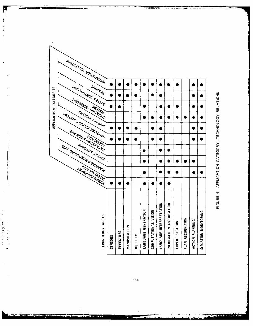
LLA 4
Ll 4 'Oi 4
4- 0
-LJ
TZ 0
40 4'9 0 .000
LU
z u nLoz z U
LU -i -
z 0 C-.l a- cc0c n L" cc z z LU zLU LL. 4 0 4 LA- CL.- u, LL <a x- -j u . 4
134

4.2.1. Division Commander's Quick Data-Access System
4.2.1.1. Description
The Division Commander's Quick Data-Access System (QDAS) would be a
briefcase-sized device intended for personal use of division commanders
to quickly obtain information on the status of available resources and
limited other situation information from data bases. It would include
voice and graphic interfaces. It could be connecLed to data lines to
provide complete access to available division automated databases, or it
could retain key resource information for limited operation in an
isolated mode.
4.2.1.2. Needs
The process of planning combat operations at division level
Involves staff study of information concerning the friendly and enemy
situation, the terrain, the weather, and many other factors. The amountof data Is voluminous and subject to rapid change. In order to focusstaff attention and speed planning, commanders must narrow the
possibilities of interest and Issue appropriate guidance to the staff.
Although some aspects of this process are interactive with the staff,
other portions are highly personal, and can be greatly speeded and
assisted by providing the commander quick access to data without
recourse to his staff. In addition, in many situations the commander
may have to make rapid decisions when staff resources are not available.
For example, if the commander has the ability to react to sudden
changes In the weather, even while on the move, he may possess the key
to winning the battle. Rapid consultation of resource data is essential
to take advantage of opportunities or compensate for unexpected
difficulties. Of course, there are many other changes that occur on the
battlefield during the course of a battle. The commander who can react
to such changes rapidly is in a superior position.
135

4.2.1.3. Employment Concept
The commander would employ QDAS whenever he wished to rapidly
obtain key resource/situation information to aid his personal thought
and planning processes. For example, it might be used prior to issue of
planning guidance to the staff, or in reacting to unexpected
developments in an operation when staff assistance was not readily
available.
At the division, the QDAS would normally be connected to the
division databases by data lines. It might be loaded with selected
information from these databases, disconnected and transported with the
commander to provide a limited capability when he was away from his
headquarters.
The system would respond to voice queries and would provide
requested data in voice or graphic form. It would interact with the
commander and would assist him in getting the particular data he wanted.
4.2.1.4. Capabilities
At the division CP, the Comnander-s Quick Data-Access System would
provide the commander with a real-time ability to query available
resource and situation databases. The system would respond to his
voice-spoken questions and provide the requested data, if it was
available, in a combination of voice and graphic display.
The system, upon voice command, could display such items as
ammunition and POL status, unit strength status, major equipment item
status, casualties, and current unit deployments.
When disconnected from the division CP data links, it should retain
should operate for a period of up to one hour on its self-contained
power supply.
136

4.2.1.5. Organization Distribution
The QDAS would be issued on the basis of one per division
commander. Officers would be trained in its use as part of their
command and staff-level schooling.
4.2.1.6. Physical Design
The QDAS would be a briefcase-sized device incorporating the
following principal hardware:
* A computer
* A word recognizer
* A speech synthesizer
* A graphics terminal.
4.2.1.7. Logical Design
This design, a reasonably short-term system with limited
capabilities, would build on existing technology for recognizing words
spoken in isolation. (A longer-term general-purpose speech
understanding system right be designed differently and would require
much more basic research.)
Figure 5 illustrates the components of the QDAS.
4.2.1.7.1. Word Recognizer
For relatively early fielding, an existing system for recognizing
isolated words could be used for this component. The word recognizer's
limitations, such as requirements for training by each user, ability to
reccgnize only isolated words, and restrictions on vocabulary size will
be the major limitations of the division commanders quick data-access
system. As the capabilities of word-recognition systems improve, these
limitations will become less severe.
137
LDATABASE
UNDERSTANDING GENERATIONSYSTEM
RECOGNIZER OUTPUT
USER
FIGURE 5 LOGICAL DESIGN OF THE DIVISION
COMMANDER'S QUICK DArA-ACCESS
4.2.1,7.2. Natural Language Understanding System
The component that interprets the spoken words and poses queries to
the database system can build on existing techniques for English access
to database. However, modifications will be required to handle the
uncertainties of the spoken input, and the differences in grammar.
Either the vocabulary would have to be limited to correspond to the
limitations of the word-recognition system, or new techniques will be
required to extend the capabilities of the word recognizer.
The natural language system should be one that is independent of
the form cr subjLtt area of the database and it should provide easy
adaptability to new databases and subject areas.
4.2.1.7.3. Text and Graphics Output
Existing techniques for generating written and spoken text from
responses to database queries could be used. New methods should be
138

devised to present the information more effectively as a mixture of text
and graphics, when that was appropriate.
4.2.1.8. Technology Gaps
The major gaps in the technology are:
Language Interpretation.
* Interpreting extended dialogs and text where meaningdepends on the context
* Interpreting language that is "ungrammatical", e.g., slangor dialect
* Interpreting uncertain input (e.g., speech)
* Recognizing continuous speech
Language Generation
*Tailoring information to fit an individual's needs
*Deciding what words and grammatical constructs to useParticipating in a dialog--when the information is storedas "words" e.g., database, when information is stored asmaps, charts, etc.
Information Assimilation
Combining infrmaiofrmultpl databases
Voie iputwit hih lvelnoise background
4.2.1.9. Evolutionary Versions
Longer-range versions of this device would be capable of
interpreting continuous speech.
4.2.2. Brigade M~ission Planning Aid
139

4.2.2.1. Description
The purpose of the Brigade Mission Planning Aid Is to provide rapid
mission planning and operations assistance to the Brigade Commander and
his key staff members in the decision/planning/execution process during
the course of a dynamic battlefield situation. The system would be
designed as a self-contained (except power supply), transportable
module, suitable for mounting in an APC or fixed facility when
available.
4.2.2.2. Needs
A continuing requirement exists on the extended battlefield for the
commander to have a rapid, responsive planning capability to enhance C2
and aid the command group in analyzing, planning, and acting more
quickly than a numerically superior enemy force. The Brigade Mission
Planning Aid would give the commander the capacity to rapidly plan
decisive maneuvers further into the future. It would increase planning
flexibility, and aid the brigade in seizing and maintaining the
Initiative at the earliest opportunity. The most efficient allocation
of all available firepower, maneuver, and target acquisition would be
facilitated by the use of a system such as the Brigade Mission Planning
Aid.
4.2.2.3. Employment Concept
The system would be used iteratively by the commander and key staff
members to aid them in planning. Based on all available data pertinent
L to a particular mission, the mission planning aid would provide timely
information regarding the best options possible to carry out a mission.
* This would entail an impact analysis to include the selection of, or
recommendations on employment of subordinate units, time phasing, routes
and alternates, plan formulation, impact on logistics, projected
casualties, and an estimate of successful outcome.
The planning aid would, in addition, postulate the possible follow-
up actions that the commander could consider in the case of success or
1.40

failure of alternatives, such as exploitation or pursuJ t options. The
mission planner would be interactive and able to adjust to a rapidly
changing combat situation. It would monitor the situation as it
developed based on a continuing Input by operators, and analyze the
impact as facts become available.
.The Brigade Mission Planning Aid would also be able to compare the
particular mission to previous missions of the same type, and for that
brigade, select options and alternatives. It would be designed to
assist in fitting the forces to the ground mission as the battleI
developed and also assist in the decisions that enable the commander to
coordinate the concentration of firepower, and consider the weather and
terrain.
The Brigade Missio'n Planning Aid would be employed at Brigade
HQ/CP, on a continuous basis.
4.2.2.4. Capabilities
The Brigade Mission Planning Aid should be able to assimilate data
by keyboard or voice entry. As the battlefield situation developed and
critical points were reached, that new data would be input as It became
available and the planning aid would analyze the ramifications, if any,
and provide further options. An operator should be able to query the
planning aid regarding, for example, recommended deployment, combat
support requirements and f ire and maneuver considerations, objective
status, etc. The results of a mission plan and status query should be
available in hard copy. The system should be able to operate either on
the power of a transporting APC or normal fixed power system.
4.2.2.5. organizational Distribution
The Brigade Mission Planning Aid would be an item of TOE equipment
in all divisions, issued on the basis of one per brigade headquarters.
Two operators and one alternate would be trained as part of their
regular duties, with one operator being designated as primary.
Maintenance would be performed within the normal organizational
structure relating to specialized computer equipment of this nature.
141

4.2.2.6. Physical Design
The Brigade Mission Planning Aid would be a transportable file-
cabinet-sized device with:
* A central computer
* A removable mass storage device
* A video display and keyboard
* Voice input and output devices
*A communications link to databases at division headquarters
*A small terminal that can be used at a distance from themain system.
The device would be completely self-contained, with the exception oef
reliance on an external power source (vehicle or normal commercial
power).
4.2.2.7. Logical Design
The primary components of the Brigade Mission Planning Aid would be
a planning system and a plan-execution monitoring system. The other
major components would be an interface to relevant databeses and good
user interface. Figure 6 shows the system's logical components.
4.2.2.7.1. Planning and Monitoring System
The general requirements of the planning and plan-execution
monitoring systems are described in Section 4.2.11. For this
application, the actions would be those that the brigade commander
plans, (e.g., troop movement, supply movement, use of firepower). As
information about the operation is received and recorded in the
database, the monitoring system would follow the plan's execution and
alert the commander if a planned action did not succeed. In such cases,
* the planner would be used to determine alternative actions that could be
performed in the new circumstances.
142

DATABASE DATABASE DATABASE DATABASE
DATABASE INTERFACE
PLANNINGAND
PLAN-EXECUTIONMONITORING
SYSTEM
USER
INTERFACE
USER
FIGURE 6 LOGICAL DESIGN OF THE BRIGADEMISSION PLANNING AID
4.2.2.7.2. Databases and Database Interface
The databases used by the planner should have the following
contents:
* Troops: status, strength, location.
* Supplies: location, amounts, information to help estimate
time to distribute items wherever needed.
* Equipment: status (who is using, is it working?), location.
* Environment: weather, terrain, hostile factors (mines,
contaminants, etc).
* Enemy status: troop & equipment strength and location,
projected actions.
* Historical information: previous operations and the actions
taken and their outcomes.
143

To the extent available, some of these data would be input and
updated from division databases by way of a link. Other elements would
be entered manually by the operator.
The form of the databases is not crucial to the design at this
stage. The databases should also be available for other purposes,
(e.g., threat projection), and consequently they should be designed for
maximum accessibility and flexibility (and hopefully with the
requirements of systems such as this in mind). For this system, the
main consideration would be to provide a means of getting the data ito
the database. Another important consideration would be to provide an
interface to the databases so they could be used in planning.
The databases must be able to assimilate new information, and to
handle incomplete and possibly conflicting information. If the
databases contain overlapping information, the interface must be able to
coordinate the information from the different databases. This is an
important area of research in database management as well as artificial
intelligence.
4.2.2.7.3. User Interface
The user interface should incorporate many of the mixed-media
features described in Section 4.2.11. As a minimum, there should be
text and graphic interfaces. At least one high-resolution color display
should be used to display maps, overlayed with graphical depictions of
troop, equipment, and supply locations, and to display graphic
representation of the plans. Input should be by voice, typing, and by
pointing to items shown on the display.
4.2.2.8. Technology Gaps
Many of the technology gaps in the Brigade Mission Planning Aid are
discussed in Section 4.2.11 in the discussions of planning, plan-
execution monitoring, and interfaces to the user. The gaps in the
technology include:
144

Action Planning
*Reasoning about alternative actions
*Reasoning about actions in different situations
*Reasoning about actions with strict time requirements
*Evaluating alternative plans under varying circumstances
*Comparing current plans with historical information
*Reasoning fast and efficiently when the situation changes
Situation Monitoring
*Plan-execution monitoring
*Detecting that goals have been accomplished based onreported actions
*Detecting that a planned action has not been successfullyexecuted
*Real-time interaction between planning and monitoring
Information Assimilation
*Combining information from multiple databases
Language Interpretation
" Interpreting extended dialogs and text where meaningdepends on the context
* Interpreting language that is "ungrammatical", e.g., slangor dialect
" Interpreting uncertain input (e.g., speech)
*Recognizing continuous speech
Language Generation
* Tailoring information to fit an individual's needs
* Deciding what words and grammatical constructs to use
* * Participating in a dialog-when the information is storedas "words" e.g., database, when information is stored asmaps, charts, etc.
* Constructing together coherent bodies of text (paragraphsor more)
* Presenting an appropriate mix of graphic and verbalinformation
145

Supporting Technologies
* Semiconductor circuits such as VHSIC
4.2.2.9. Evolutionary Versions
A preliminary version of this system could be a simple database
access system. This could evolve to a version that suggests
alternatives, without evaluating them.
4.2.3. Emergency Repair and Maintenance Advisor
4.2.3.1. Description
The Emergency Repair and Maintenance Advisor (ERMA) would be a
small module to be used by combat or combat-support vehicle crewmen to
obtain expert advice on poss ale ways to repair their equipment in
2mergency situations. It would be a self-contained hand-held unit,
incorporating a microprocessor, input/output, and an expert system
covering repair possibilities.
4.2.3.2. Needs
The growing complexity of Army equipment makes it more and more
difficult for the soldier to devise and implement means to keep the
equipment operating in situations where maintenance support is not
available. In cases where damage renders the equipment useless, without
lestroying it, normal or unusual on-the-spot procedures may be able to
temporarily restore some or all of the equipment's functions. ERMA is
intended to increase the capabilities of the crew to devise and execute
such procedures.
* As battlefield operations move toward the air-land battle 2000
concepts, units will become more and more isolated from maintenance and
repair support, enhancing the need for resourcefulness in keeping
* equipment operating. In addition, the requirements of continuous combat
will enhance the need for prompt independent repair activities to
maintain momentum despite minor equipment failures or damage.
146

4.2.3.3. Employment Concept
The ERMA would be used in emergency situations when repair beyond
the normal operator maintenance level is urgently needed and cannot be
obtained from normal maintenance channels. Repair may be needed as a
consequence of system failure or combat damage. Vehicle operators or
crew members would use it to try to diagnose the problem and determi'ne
whether or not some solution that could restore the vehicle to action
were possible, using immediately available resources. If the dialogue
were successful in reaching a diagnosis and possible course of action
for repair, the system would then instruct the operator in a step-by-
step temporary repair procedure. The ERMA would be issued and carried
as an item of on-vehicle materiel (011K) with the vehicle it pertains to.
The same hardware module may be loaded with different software
pertaining to different vehicles. When a vehicle was disabled, and the
operator recognized that restoring it to action was beyond his
knowledge, he would resort to ERMA for advice.
If vehicle battery power vere available, the operator would connect
the ERMA to the battery. If not, it would be capable of operating for a
limited period on Its own Internal power supply. The operator would
engage in a dialogue with ERMA, using either voice, keyboard, or graphic
input, and would receive graphic and voice output. The dialogue would
include prompting and questioning from ERMA to obtain data on the nature
of the problem, and whether or not the operator could obtain useful
resources (for example, a piece of conducting wire).
In Its memory, the ERMA would retain a record of the diagnosis and
of what actions were taken; this record could be reviewed by DS or GS
maintenance personnel when it was possible to obtain their assistance
with more permanent repairs.
4.2.3.4. Capabilities
The ERMA should be capable of providing advice equivalent to the
Army's best trained and most experienced maintenance personnel. It
should operate for onr hour on its internal backup power, or
147

indefinitely on standard vehicle power. It should be rapidly loaded
with software for different vehicles employing a separate program change
unit (PCU). Programs themselves would be provided in the form of
preloaded read-only-memory units for use in the PCU. Their structure
would be such that they could be modified to accommodate vehicle
modifications or improved knowledge on vehicle repairs. The programs
would be regularly updated to reflect such changes.
4.2.3.5. Organizational Distribution
The ERMA would be issued on the basis of one per combat or comb it
support vehicle in all divisions and corps artillery battalions. PCUs
would be issued on the basis of four per division. Expert programs
would be supplied through maintenance supply channels.
The ERMA and PCU would be maintained within the normal division
structure.
4.2.3.6. Physical Design
ERMA would be a small briefcase-sized device with the following
hardware:
* A small computer with replaceable mass-storage
* A small terminal with a keyboard and display
* Voice Input device
* Voice output device.
4.2.3.7. Logical Design
The Emergency Repair and Maintenance Advisor would primarily
contain an expert system and a repair advisor. The expert system would
encode diagnostic rules plus a model of how the system worked to help
with cases rules did not cover. Input to the system would be from the
* operator. Figure 7 Indicates the logical components of the system.
The expert system and repair advisor would be the same for all
equipment. However, each item of equipment (e.g., M60A3 tank, M113
148

EXPERT'SMOEOFRPIRULES EQUIPMENT MANUAL
EXETREPAIR HISTORY OFSYSTEM ADVISOR REPAIRS
SUSER USER
tUSER
FIGURE 7 LOGICAL DESIGN OF THE EMFRGENCY REPAIR ADVISOR
model, and repair manual, although many elements would be the same among
them. The parts that differed with each class would reside on a
removable ROM or other form of mass storage, so they could be
transferred from one unit to another and updated with changes to the
equipment.
4.2.3.7.1. Expert System
An expert system, as discussed in Section 4.2.11 would be used in
this system. It should be an extension of expert system technology in
order to be able to easily handle more than one type of equipment and to
make effective use of a physical/electrical model of how the equipment
worked. With such a model, deductions could be made about possible
problems when failures occurred. This information might also be used to
modify the rules to reflect local equipment modifications.
149

4.2.3.7.2. Repair Manual
The repair manual would be an on-line manual that could be indexed
by the failures that had been detected by the expert system. Using
videodisk or other technology, it could contain still and moving
pictures of the equipment as well as written information.
4.2.3.7.3. Repair Advisor
The repair advisor would use the Information in the repair manual
and the model of the eqilipment to advise the person on how -o perform
the repair. The completion of each step would be reported as it was
performed. Periodically, the advisor might ask for additional
confirmation that the steps were being performed as indicated.
Simple repairs could be prestored sequences of steps. However,
mnore complex repairs or unusual situations would require some planning
by the repair advisor. A planning system that used the information in
the manual augmented with descriptions of general repair act tors would
be incorporated and used to plan some nonstandard repairs.
-'he advisor would record equipment failures and repairs undertaken
for future reference.
4.2.3.7.4. User Interfaces
The ERMA should be able to tailor its presentation of iniormation
to the using individual so that it would provide information in the most
suitable form.
A small display would be available to provide pictures or diagrams
of appropriate parts, and voice input and output would be available to
free the person's hands and enable hiim to interact while performing
repairs.
4.2.3.8. Technology Gap
In addition to the gaps existing in the basic planning, expert
system, and interface components, the following gaps currently exist in
the other technologies:
150

Expert Systems
" Getting the proper information into rules
" Methods for eas'ly changing rules
" Representing basic repair actions for use by the repair
adviso
" Encoding information in tle repair manual so it can be used
by the repair advisor
* Using causal models in liagnosis
* Reasoning with incomplete, uncertain, and possiblyconflicting inf~rmation
Developing general-purpose expert systems that can handle a
range of similar problems
Information Assimilation
* Combining inf-rmation from multiple databases
* Determining what information to acquire to help establish
the certainty of information
* Combining and reasoning with incomplete and inconsistent
information
Language Interpretation
* Interpreting extended dialogs and text where meaning
depends on the context
* Interpreting indirect or subtle utterances, such as
recognizing that "Can you reach the salt" may be a requestto pass it
* Interpreting language that is "Lgrammatical", e.g., slang
or dialect
* Interpreting uncertain input (e.g., speech)
Recognizing continuous speech
Language Generation
* Tailoring information to fit ai. individual's needs
* Deciding what words and grammatical constructs to use
* Participating in a dialog--when the information is stored
as "words" e.g , database, when information is stored asmaps, charts, etc.
* Presenting an appropriate mfx of graphic and verbal
information
151
Supporting Technologies
*Voice input with high level noise background
*Semiconductor circuits such as VHSIC
4.2.3.9. Evolutionary Versions
In the nearer term, the system could be limited to diagnosis and
providing a smart Index to a repair manual.
4.2.4. Interrogation Support System
4.2.4.1. Description
Intelligence units are tasked with an interrogation mission whose
success is largely dependent on the timeliness and accuracy of response
information. The Interrogation Support System (ISS), would be a
portable device designed to provide the trained human interrogator with
a tool to assist in and facilitate the rapid and thorough forward
exploitation of POW/detainees for essential elements of information
(EEI).
4.2.4.2. Employment Concept
Prior to employment, the ISS would be updated with appropriate
intelligence information by a combination of automated input from
divisional databases and manual entry of information such as EEI, and
knowledge of the interrogation subject by the interrogator. At the
interrogation site, the system would be uised interactively by the
interrogator, either in the presence of the subject or in isolation.
Use could be effectively integrated with other techniques in the
interrogation process to aid In producing desired psychological impacts
on the subject.
The 155 would contain the EEI related to a particular interrogation
and have the capability to detect inaccuracies in responses, lies, and a
true response in satisfaction of those EEl. The module would be able to
update and integrate the EEl as more, new, or conflicting data was input
by the interrogator.
152
4.2.4.3. Needs
Efforts by the interrogator to meet requirements for efficient,
rapid, and accurate forward exploitation of interrogation opportunities
to satisfy EEI could be greatly aided by the employment of the
Interrogation Support System. This system could aid in the
determination of the validity of all detainee responses and, thereby,
assist in the assessment of the potential value to intelligence of the
information obtained. Further, it would aid in assessing the need for
more prolonged detainee questioning for exploitation purposes. The
human interrogator would be greatly assisted by having information gaps
for a particular mission filled in by the ISS, as well as having
responses integrated with other intelligence information so that
variables such as conflicting, misleading data could be rapidly
resolved.
4.2.4.4. Capabilities
The ISS would have the basic capability of assessing interrogation
responses for pertinence and accuracy. In addition, it would have the
capability of formulating questions and recommending questions based on
deduction and inference from the information it knows and the
information it receives.
4.2.4.5. Organizational Distribution
The Interrogation Support System would be a TOE item in the
Division 86 CEWI Battalion, issued on the basis of one per CEWI
Battalion. All interrogators would be trained in its use as part of
their school training. It would be maintained in normal division
maintenance channels.
4.2.4.6. Physical Design
The Interrogator would be a small, portable device, incorporating
the following hardware:
153

*A computer
*Removable mass storage*Keyboard and display
*Simple speech input and output devices.
4.2.4.7. Logical Design
The basis of this system would be a component that could correlate
new information with existing information and perform the following
functions:
(1) Determine if the new information conflicts with currentinformation.
(2) Integrate any useful new information Into the existingdatabases.
(3) Determine what further information might be of value andrequest it.
This system could be viewed as a special case of information
integration. The key difference is that for the Interrogator, the
newly-acquired information would not be assumed to be reliable and one
of the purposes would be to ascertain its reliability. Many of the
techniques used in other information integration problems would be
applicable here; development of others would be required.
Figure 8 illustrates the logical design components of the
interrogator.
4.2.4.7.1. Conflict Detection
The portion of the system that would detect conflicts would use
methods for reasoning with uncertain and incomplete information to
determine if the newly-acquired information appeared accurate. Since,
in this system, the new information would not be assumed reliable,
existing methods might require some revision or extension.
154

EDATABASE
INFORMATION INTEGRATIONAND
CONFLICT DETECTION
NEWK
INFORMATION QUESTIONS
USERINTERFACE
INTERROGATOR
FIGURE 8 LOGICAL DESIGN OF THE INTERROGATOR
4.2.4.7.2. Information Integration
If the information were judged reliable, the same information
integration techniques that have been described elsewhere could be used
to update the database.
4.2.4.7.3. Posing New Questions
Deciding what further information was required, and what questions
to ask would be somewhat similar to the information-gathering problem
described for the River Reconnaissance System. The development of
techniques for doing this is still a basic research issue in artificial
155
_____ ____;t,%
4.2.4.7.4. User Interface
The system should be able to interact with the interrogator in
English. The interaction could be either written or spoken. A graphic
display for use of maps and diagrams should also be provided.
4.2.4.8. Technology Gaps
In addition to the technology gaps in interfaces, the following
areas require further research:
Language Generation
" Tailoring information to fit an individual's needs
" Deciding what words and grammatical constructs to use
*Participating In a dialog--when the Information Is storedas "words" e.g., database, when information is stored asmaps, charts, etc.
Language Interpretation
*Interpreting extended dialogs and text where meaningdepends on the context
*Interpreting indirect or subtle utterances, such asrecognizing that "Can you reach the salt" may be a requestto pass it
* Interpreting language that is "ungrammatical", e.g., slangor dialect
" Interpreting uncertain input (e.g., speech)
* Recognizing continuous speech
Information Assimilation
*Combining information from multiple databases
*Determining that information is lacking
*Determining what information to acquire to help establishthe certainty of information
*Combining and reasoning with incomplete and inconsistentinformation
Situation Monitoring
*Recognizing if the information obtained has achieved thedesired goal
156

Supporting Technologies
*Voice input with high level noise background
*Semiconductor circuits such as VHSIC
4.2.4.9. Evolutionary Stages
A nearer-term version could be limited to the capability of
detecting conflicts between responses and a database.
4.2.5. Tank Ammunition Handler
4.2.5.1. Description
The Tank Ammunition Handler would be a robotic device mounted on
platforms used to carry tank ammunition. A 2-1/2 ton truck was chosen
for this design. The device would be composed of three robotic arms,
which work in conjunction to perform all actions to remove ammunition
7 from pallets and hand it to a crewman inside the tank for final storage
in racks. It would perform the operation of cutting bands, opening
cannisters, removing the rounds and lifting/moving them to a position
from which a single crew member can handle the final aspect of storage.
4.2.5.2. Needs
Rapid load out of Army units from peacetime bases is a critical
aspect of readiness. This is particularly true in Europe, where units
have great difficulty in meeting the tight time limits for clearing
their bases. In a combat situation, rapid rearming of tanks is
important to maintain momentum and to make the most use of critical tank
resources.
The present manual system for rearming a tank is time consuming and
* labor intensive. A tank crew can be expected to take 3-to-4 hours to
complete rearming. All four crew members must work intensively to
* aicomplish the task. The Tank Ammunition Handler substitutes a robot~c
device for troop labor. In addition, the device can reload at the speed
of the crew member placing the rounds in the ammunition racks.
157

As visualized in this design concept, the Tank Ammunition Handler
could reduce the rearming time to approximately one hour.
4.2.5.3. Employment Concept
The Tank Ammunition Handler would perform the ammunition
preparation and handling functions in the rear or well forward ir, the
battle area. In rear areas, it may be employed to speed the outloading
of armor units from their peacetime bases, thus aiding in meeting the
critical time requirements for load out and movement to assembly areas.
In forward areas, it may be used to service armor units between
engagements, handling complete or partial reloads as time and resources
permit.
In reloading operations, the Tank Ammunition Handler would be
positioned near the tank and the ammunition supply, which may be on
pallets or loose, on ammunition carriers or on the ground. Once
positioned, the device would be controlled completely by a single crew
member, inside the tank, allowing other crew members to perform other
critical tasks such as maintenance or to rest. The crew member (loader)
would instruct the device on the type and sequence of rounds to be
furnished to him and on the route to be used by the device t( pass the
round to him through the tanks complex interior arrangement.
When instructed, the device would secure a round, prepare it,
remove it, and hand it to the loader. If desired, it would take a spent
cartridge from the loader and discard it outside the tank.
4.2.5.4. Capabilities
The Tank Ammunition Handler should be able to deliver one round per
* minute. It would perform all labor intensive functions of removal from
* ipallets and cannisters and moving the round which are presently
performed by the tank crew. The device could be completely controlled
by the loader inside the tank. It would be designed to avoid
transmitting any NBC contamination that might remain on cannisters to
the rounds and subsequently into the tank.
158
4.2.5.5. Organizational Distribution
The Tank Ammunition Handler would be issued to armor battalions on
the basis of one for each ammunition carrier. It would be maintained in
normal division maintenance channels.
4.2.5.6. Physical Design
Figure 9 shows a design concept. It would be able to reload a
tank from a pallet of cannistered rounds on the ground, but it could
also take rounds from the conveyor of the Army's proposed Armored Supply
Vehicle. The system could operate even in the presence of NBC
contamination on the ammunition cannisters, without exposing the crew or
tank interior to contamination. It could remove spent cartridges or dud
rounds from the tank interior.
The system would include three different robot arms mounted on the
bed of a 2-1/2 ton truck. All three arms would operate simultaneously
in a coordinated way to speed the loading process. The arms would
perform these three tasks:
(1) Taking the cannisters from the pallet -- the
"depalletizing" arm.
(2) Lifting the cannisters to the hatch -- the "loading" ai,.
(3) Handing the rounds inside the tank -- the "high-
flexibility" arm.
The depalletizing and loading arms would be mounted permanently on
a rectangular steel frame that fits within the bed of any 2-1/2 ton
truck. The frame would also have a rack that would carry the high-
flexibility arm. As the first step of the rearming process, the loading
arm would lift the high-flexibility arm up onto the tank, where it would
attach itself firmly in place over an open hatch with strong magnets.
. The three arms then would begin to operate, each performing a different
part of the ammunition-loading task.
159

t"'
FIGURE 9 TANK AMMUNITION HANDLER DESIGN CONCEPT
1
160

4.2.5.6.1. Arms
The depalletizing arm would be especially designed to be able to
cut the retaining bands from a pallet of cannisters, remove one
cannister at a time, identify the type of round in it, take its top off,
and pass it to the loading arm. It would use some auxiliary equipment
mounted nearby on the frame to help in these tasks.
The loading arm would be designed to be able to take an opened
cannister, with a round still inside it, from the depalletizing arm and
hand it up to the high-flexibility arm (Figure 10), the loading arm
would tip the round out of the cannister into the high- flexibility
arm's gripper. Finally, it would discard the shipping cannister.
FIGURE 10 TANK AMMUNITION HANDLER HIGH FLEXIBILITY ARM
The high-flexibility arm would carry the round down through the
hatchway and into the tank, to a point near the rack that is being
loaded. There, a crewmember would take the round and manually insert it
into its proper place in the storage rack. Before the arm retracts, the
crewmember could also take a spent cartridge or dud round from the rack
and put it into the gripper to be carried out and discarded.
161
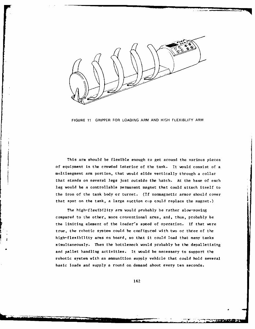
FIGURE 11 GRIPPER FOR LOADING ARM AND HIGH FLEXIBLITY ARM
This arm should be flexible enough to get around the various pieces
of equipment in the crowded interior of the tank. It would consist of a
miltisegment arm portion, that would slide vertically through a collar
that stands on several legs just outside the hatch. At the base of each
leg would be a controllable permanent magnet that could attach itself to
the iron of the tank body or turret. (If nonmagnetic armor should cover
that spot on the tank, a large suction cup could replace the magnet.)
The high-flexibility arm would probably be rather slow-moving
compared to the other, more conventional arms, and, thus, probably be
the limiting element of the loader's speed of operation. If that were
true, the robotic system could be configured with two or three of the
high-flexibility arms on board, so that it could load that many tanks
simultaneously. Then the bottleneck would probably be the depalletizing
and pallet handling activities. It would be necessary to support the
robotic system with an ammunition supply vehicle that could hold several
basic loads and supply a round on demand about every ten seconds.
162

If the tank had to button up unexpectedly (due to conventional or
chemical attack), the high-flexibility arm could go limp and be
retracted quickly, but a crew member would be required to help guide it
out. Once the arm c'eared the hatch opening, the hatchcover could be
c losed.
4.2.5.6.2. Grippers
Figure 11 shows the gripper of both the loading arm and the high-
flexibility arm. Several flexible, pneumatic, prehensile fingers would
hold a cannister or round firmly, but with no danger of squeezing too
hard and deforming it, as a mechanical gripper might. The compliant
fingers would also adjust automatically to the shape of a cannister or
round, enabling the robotic system to handle different types and
calibers of ammunition.
4.2.5.6.3. Sensors
The device would have a video camera for use in finding the
cannisters that the depalletizing arm is to grasp. For simplicity, the
existing cannister marking could be augmented with simple codes
identifying the different rounds they contain. This would enable the
use of existing vision systems for identifying a small number of
objects.
4.2.5.6.4. Interface
The Tank Ammunition Handler would normally communicate with the
loader inside the tank through a wire data link to take the order for
ammunition or to advise him of any operating problems. At any time
during loading, the loader could ask the robot to bring a particular
- type of round next. These would be simple voice commands that could be
,a processed with current speech-recognition technology. The loader could
also use an input device mounted on the gripper of the high-flexibility
arm for this communication. This might be a simple keypad or a
microphone.
163

4.2.5.7. Logical Design
The control software for the loading arm and the high-flexibility
arm could be relatively simple, because the crew member could easily
train their motions. They would only have to repeat those "-itions, and
would need only minimal sensory feedback.
4.2.5.8. Technology Gaps
Sensing
* Tactile sensors for touch, such as artificial skin
* Tactile sensors for force/torque
Effecting
* Mechanical arms
* End effectors such as hands, fingers
Manipulators
* Planning and monitoring manipulator actions, e.g., planninghow to assemble something
* Planning and controlling arm movement: trajectory planning
and monitoring
* End effector planning and monitoring, e.g., grasping,placing peg in hole
* Automatically detecting unexpected occurrences andmalfunctions and recovering from them
Language Interpretation
* Interpreting language that is "ungrammatical", e.g., slangor dialect
* Interpreting uncertain input (e.g., speech)
* Recognizing continuous speech
Supporting Technologies
* Arm, leg, and gripper components
* Voice input with high level noise background
* Semiconductor circuits such as VHSIC
164

4.2.5.9. Evolutionary Versions
This device could be fielded in three stages:
* Loading arm only
* Loading and depalletizing arm
* Complete system.
4.2.6. Mine Clearer
4.2.6.1. Description
The Mine Clearer would be an autonomous vehicle designed to aid the
combined arms team in breaching minefields of all types. It would be
equipped with sensors and mine neutralizing devices that would permit it
to rapidly traverse mined areas, avoiding mines if possible,
neutralizing them if necessary, and marking the resulting safe lanes.
4.2.6.2. Needs
The enemy employs mines to disrupt and slow forces trying to
penetrate his positions. Mines are normally employed in groups and
cover the front lines in both breadth and depth. Doctrine dictates that
minefields are always covered by fire.
The breaching of such a minefield is both dangerous and time-
consuming. Friendly troops must quickly breech the minefield in order
to maintain the momentum of the attack and preclude being pinned down
and delayed. Therefore, a device is needed that quickly and efficiently
clears a path while at the same time, does not expose the friendly
combined arms team to either the effects of mines or to the enemy
covering force.
4.2.6.3. Employment Concept
In the offense, Mine Clearers would be employed in teams of two,
accompanying forward elements of the combined arms team. One of the
Mine Clearers would be deployed with the forward echelons prepared for
offensive combat. Upon detecting of an enemy mine area and deciding to
165
t

cross it, the forward team would activate the Mine Clearer to provide a
clear path through the minefield of sufficie~nt width to allow prompt
safe passage of the area by the forward element (platoon size). The
second Mine Clearer would accompany the rest of the unit, widening the
path to permit more rapid crossing. The first Mine Clearer would
continue accompanying the unit and the second would remain behind to
continue widening for following elements, systematically broadening the
path to four-or-five-vehicle width. The Mine Clearers continue to
leapfrog until the unit halts its offensive. If necessary, the
minefield paths would be further broadened by reserve elements, using
other Mine Clearers.
During movements when it was not actually performing clearing
operations, the Mine Clearer would be teleoperated to follow one of the
mechanized vehicles of the combined arms team.
4.2.6.4. Capabilities
During clearing operations, the Mine Clearer would move at a fast
rate, avoiding nines wherever possible and marking the lane as it
traverses the minefield. Its on-board sensors would allow it to act
autonomously, stopping only to disable mines it could not avoid. Tt
would be able to identify and recognize standard mine patterns andI
detect and disable all types of antiperso.inel and antitank mines.
During movement, when it was not actually performing clearing
operations, the Mine Clearer would be capable of cross-country speeds
comparable to the supported units maximum rate of advance (on the order
of 40 km/hr). Its range would be comparable to other mechanizee
vehicles in the combined arms team.
4.2.6.5. Organizational Distribution
The Mine Clearer would be a TOE item assigned to the combat arms
team on the basis of two per armor or mechanized infantry battalion.
They would be operated by battalion personnel and maintained in engineer
channels.
166

4.2.6.6. Physical Design
The Mine Clearer (see Figure 12) would be an autonomous vehicle
consisting of several devices mounted on a horizontal frame. In order
from the front of the machine to the back, they are
*A mine detector. This would be a multisensor device, ableto integrate indication3 from several kinds of sensors,such as acoustic, electromagnetic, and optical, andsubsurface tactile probe~s to recognize surface mines and
locate buried mines. Based on assessment of these data,the Mine Clearer would elect either to alter its crossingIpath or neutralize the detected mines.
*A blastproof roller and signature simulator that woulddetonate most mines, both antipersonnel and antitank. Tomake it easier to steer, and to allow it to conform moreclosely to the terrain, the roller might consist of a stackof discs on edge. Each disc would be hydrostaticallysprung to exert the same ground pressure.
*A demolition mechanism for destroying mines in place, alsounder armor.
*A drive mechanism.
4.2.6.6.1. Locomotion
The roller would be in constant contact with the ground and support
the front of the frame, which in turn would support the other devices.
The drive mechanism would support the rear of the frame. All the
devices would be slightly wider than the widest vehicle that would use
the cleared path.
4.2.6.6.2. Special Devices
The mine-demolition device would consist of an armor-lined
cylindrical cap that the Mire Clearer places over the mine. It would
then pump fuel through spray nozzles into the space under the cap to
fill it with an explosive fuel-air aerosol. It would then detonate the
mixture at many places over the inner surface of the cap simultaneously
with multiple spark plugs. This would cause a focused shock wave to
propagate radially towards the center of the cap, delivering a large
impact to the mine there, and inducing a sympathetic detonation in its
167
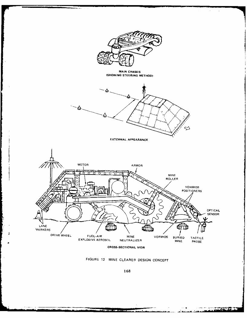
MAIN CHASSIS(SHOWING STEERING METHOD)
EXTERNAL APPEARANCE
/MOTOR ARMOR
0 ROLLER
VORMIDS
~OPTICALSENSOR
LANE Avg
EXPLOSIVE AEROSOL NEUTRALIZER MINE PROBE
CROSS-SECTIONAL VIEW
FIGURE 12 MINE CLEARER DESIGN CONCEPT
168

explosive charge. Shock absorbers between the cap and the frame would
absorb the impacts of the fuel-air explosion and the explosion of the
mine.
This procedure should destroy most mines. In those cases where it
fails (i.e., the mine detector show!7 that the mine is still there), the
Mine Clearer would modify its route to bypass the mine.
At periodic intervals along the path, the Mine Clearer would mark
the cleared path by ejecting plastic cones or light sticks. Any path
marked as cleared would have been proofed in two different ways: with
the mine detector and with the roller. Thus, the probability of a
missed mine would be reduced to an acceptably low level.
4.2.6.6.3. Sensors
Multiple sensors would be available for surface mine detection,
including vision, infrared, millimeter radar, acoustic ranging, laser
scanning, probes, and metal detectors. Underground mines present more
difficult problems. Some instruments to consider in addition to the
Army's Vehicular Off-Road Mine Detection System (VORMIDS) include the
gamma-ray backscatter sensor and the gas chromatograph to analyze the
chemical composition of the object.
4.2.6.6.4. Power
The Mine Clearer would have a conventional gasoline or diesel
engine.
4.2.6.7. Logical Design
The principal logical components of the Mine Clearer would be a
navigation system that would attempt to find a route through the mine
field, disposing of mines when necessary, and a mine-recognition system
that would locate and identify mines. These components are illustrated
in Figure 13.
169

SENSORS PROPULSION I
MINE MARK RO
DETECTION
PLANIN 2 MODIFICATION
E MINEDIOSAL
FIGURE 13 LOGICAL COMPONENTS OF THE MINE CLEARER
4.2.6.7.1. Mine Recognition
The component for locating and identifying mines would incorporate
techniques for interpreting visual and other sensory information in
order to recognize and identify objects. This would require multi-
sensory integration and image processing. Some techniques are already
available, others will have to be developed to detect buried mines, and
other unusual situations.
4.2.6.7.2. Navigation
The navigation component of the Mine Clearer would be responsible
* ,for finding a path through the mine field, avoiding minor or other
obstacles, or deciding to disable mines as necessary. This requires the
ability to plan and follow a route. One of the major aspects is
* deciding for each mine whether to go around it or somehow dispose of it.
Simple navigation (route planning) techniques, as discussed in
170
Section 4.2.11, could be used to decide the relative merits of stopping
to disable a mine versus gcing around it. As the clearer moves, it
would mark the path. If it must back up to avoid an obstacle, markings
would indicate the altered path.
If a mine is to be disabled, the clearer must decide how best to do
that. The decision to employ the demolition device used in this concept
could be based on simple non-AI-type techniques. However, in the
future, more disposal methods for new types of mines might be developed
and the decisions about which to use may be complex. In that case,
artificial intelligence type planning and decision-making methods will
be incorporated into the system.
4.2.6.8. Technology Gaps
The main technology gaps of the Mine Clearer are:
Sensing
* Tactile sensors for probing and for touch, such as
artificial skin
Mobility Control
* Route planning and monitoring
* Steering
* Automatically detecting unexpected occurrences and
malfunctions and recovering from them
Computational Vision
* Representing knowledge about objects (particularly shape
and spatial relationships) and developing methods forreasoning with that knowledge
* Understanding the interaction between low-level information
and high-level knowledge and expectations and developing
methods for combining the two
* Detecting the presence of an object or event
* * Recognizing objects, including reliable IFF
* Locating objects
171

Information Assimilation
* Combining information from multiple sensors
* Determining what information to acquire to help establish
the certainty of information
* Combining and reasoning with incomplete and inconsistent
information
Action Planning
* Reasoning about alternative actions
* Reasoning about actions in different situations
* Evaluating alternative plans under varying circumstances
* Reasoning fast and efficiently when the situation changes
* Route planning and following
* Planning to acquire information
Situation Monitoring
* Plan-execution monitoring
* Detecting that a planned action has not been successfully
executed* General situation monitoring
Supporting Technologies
* Sensors for determining position and orientation in the
battlefield
* Sensors for locating mines
* Sensors for detecting nearby (within approximately 10 m)objects
* Solid-state color TV cameras
* Power supplies: batteries, fuel cells, nuclear generators
* Semiconductor circuits such as VHSIC
4.2.6.9. Evolutionary Versions
* A short-term version of a Mine Clearer employing teleoperation and
projected line charges may be feasible. A demonstration program for
this approach is underway in DARCOM. This demonstration Mine Clearer is
capable of breaching an enemy minefield in either a hasty or deliberate
172

mode. In the hasty mode, the Mine Clearer becomes vulnerable to enemy
countermeasures because it is on the back azimuth of the line charge
explosion and can be targeted. In the deliberate mode, it propels the
line charge which is either delay fuzed or command detonated, allowing
the Mine Clearer to stand off and not be located by the back azimuth.
4.2.7. Tactical Threat Projection System
4.2.7.1. Description
The Tactical Threat Projection System (TTPS) would be an artificial
intelligence system intended for internal use at division and higher
headquarters. It would be integrated with other automated software and
hardware components of the division headquarters. Based on continuous
data inputs on the tactical situation, the TTPS would be able to project
and isolate the most probable courses of action of enemy forces, and the
manner in which the threat could manifest itself.
4.2.7.2. Needs
In order to defeat a numerically superior enemy force with a
doctrine of continuous combat, the tactical commander must have the
capacity and the opportunity to employ decisive firepower and maneuver.
One of the major elements contributing to this is timely combat
intelligence, which is needed to influence the course and outcome of the
battle. The Tactical Threat Projection System, by integrating knowledge
of enemy doctrine and tactics with real-time intelligence would assist
in the rapid identification of enemy courses of action, including
follow-up echelon plans. Friendly assets could then be focused on the
targets most critical to enemy success, and decisive countermeasures
could be employed with advantageous lead time.
4.2.7.3. Employment Concept
The Tactical Threat Projection System would have the capability to
assess and project threats, providing alternatives for countering a
particular threat posture. This would include the threats associated
173
LA -A,

with force-on-force situations as well as the possible enemy employment
of NBC, artillery deployment, air defense, attack helicopters, EW, enemy
advantages and vulnerabilities, and deviation from doctrine.
Based on a threat projection assessment, the TTPS would identify as
many feasible options as possible and would provide as much lead time as
possible for countering evolving tactical threat situations. This would
include advice on the employment of countermeasures (when, where, and
how), the most advantageous use of terrain, and the advantages and
disadvantages of tactical options in light of the opposing threat.
The TTPS would automatically assimilate as much of its needed data
as possible from other automated C2 components; additional input would
be provided by keyboard entry.
4.2.7.4. Capabilities
The TTPS would be capable of operating as an integrated part of
automated division command and control elements. It would be capable of
near-real-time analysis and output, based on continuous monitoring of
the tactical situation and intelligence inputs.
4.2.7.5. Organizational Distribution
Used at division headquarters, the Tactical Threat Projection
System would be a module integrated with other present or planned C2
systems, such as the All Source Analysis System (ASAS). One operator
and one alternate would be trained as part of their regular duties.
Maintenance would be performed within the normal organizational
structure.
4.2.7.6. Physical Design
The Tactical Threat Projection System would use the following
hardware:
* Color displays
* Multiple input and output devices such as keyboard,
digitizing tablets, and speech recognizers andsynthesizers.
174
1

To the maximum extent possible, hardware for the TTPS would be
integrated with other divisional automated C2 components.
4.2.7.7. Logical Design
Figure 14 illustrates the components of the Tactical Threat
Projection System.
OBSERVERS
INFORMATION
INTEGRATION
RECOGNITION
i t
USERINTERFACE
USE R
FIGURE 14 LOGICAL DESIGN OF THE TACTICAL THREATPROJECTION SYSTEM
4.2.7.7.1. Databases
The information used for tactical threat projection would be spread
over a number of large databases. It would include up-to-date
intelligence information oni areas such as enemy status, position, and
175
4

movements. In addition, information about enemy doctrine, past actions,
etc. would be available. Some of this information might be used for
other purposes, such as a planning aid for a brigade or other commander.
The format of the databases could be varied as long as an interface was
provided so that each database would be accessible by the systems using
it.
4.2.7.7.2. Information Integration
This component would contain techniques for combining the
information that was available in the various databases. Since that
data might be uncertain, incomplete and possibly conflicting, methods
for integrating it would have to be devised for this purpose. The
integrated databases would then be used by the plan recognition and
planning components.
4.2.7.7.3. Plan Recognition
Plan recognition techniques would be used to infer enemy plans and
goals. Development of these techniques is still in the basic research
stages.
4.2.7.8. Planner
Planning, such as described for the Brigade Mission Planning Aid,
would be used to determine the actions available in a given situation.
If there were several alternatives, the planner would be used to assess
their relative likelihoods and suggest actions accordingly.
4.2.7.8.1. interface
* The interface to the user would be essentially the same as that
* described for the Brigade Mission Planning Aid.
176

4.2.7.9. Technology Gaps
In addition to the gaps in planning and user interfaces, the
following areas require further research:
Information Assimilation
*Combining information from multiple sensors
*Combining information from multiple databases
*Combining new information with existing information
*Determining that information is lacking
*Determining what information to acquire to help establish
the certainty of information
*Combining and reasoning with incomplete and inconsistentinformation
Situation Monitoring
* Recognizing if the information obtained has achieved the
desired goal
* Detecting that goals have been accomplished based onreported actions
*Detecting that a planned action has not been successfully
executed
*Detecting important changes in a situation
*Inferring a plan based on observations of Individualactions
Action Planning
*Reasoning about alternative actions
*Reasoning about actions in different situations
*Reasoning about actions with strict time requirements
*Evaluating alternative plans under varying circumstances
*Comparing current plans with historical information
Language Interpreta ion
*Interpreting extended dialogs and text where meaningdepends on the context
*Interpreting indirect or subtle utterances, such asrecognizing that "Can you reach the salt" may be a requestto pass it
177

* Interpreting language that is "ungrammatical", e.g., slang
or dialect
* Interpreting uncertain input (e.g., speech)
* Recognizing continuous speech
Language Ceneration
* Tailoring information to fit an individual's needq
* Deciding what words and grammatical constructs to use
* Participating in a dialog--vhen the information is stored
as "words" e.g., database, when information is stored asmaps, charts, etc.
* Constructing together coherent bodies of text (paragraphs
or more)
* Presenting an appropriate mix of graphic and verbal
information
Supporting Technologies
* Semiconductor circuits such as VMSIC
4.2.7.10. Evolutionary Versions
State-of-the-art Al techniques could be incorporated in planned
£sion C2 systems, in areas such as database access.
4.2.8. Safe Return Controller
4.2.8.I. Description
The Safe Return Controller would be an intelligent system that
could assume control of an Army helicopter or airplane when the pilot
became disabled. The Controller would stabilize the aircraft, assume a
predetermined safe altitude and return control to the autopilot to
return to a friendly airfield. It could be overruled by the pilot until
it again senses pilot dysfunction. The system could be an avionics
component that would use information from other aircraft instruments.
It would employ any available autopilot system as an aid in implementing
the actions it decided to take.
178
The system would allow for the consideration of eliminating the
copilot (where applicable), and allow the recovery of an aircraft that,
except for a disabled pilot, would be able to fly or, in the case of a
helicopter, to gyro-rotate to the earth.
4.2.8.2. Needs
The ability to safely recover an aircraft when the pilot became
disabled, would conserve valuable Army resources. In addition to
aircraft, passenger and crew lives could be saved. When the systkm
fully evolved, the copilot might be replaced. This latter factor
indicates the potential for a significant savings in manpower and system
life cycle cost.
4.2.8.3. Employment Concept
The AI Safe Return Controller would be an aircraft backup to
temporarily replace the pilot should he become disabled. Its function
would be to allow an aircraft without a functioning pilot to return
safely.
When the Safe Return Controller sensed the conditions that
indicated the pilot was not properly piloting the aircraft, it would
announce that it would assume control of the aircraft. Should the pilot
not be disabled, he would cancel the controller. This notice would
alert the pilot to a flight problem and require a positive response.
Should the pilot not respond, the controller would Immediately identify
the critical flight problem (as a pilot would), and determine an
appropriate course of action to stabilize the aircraft. The next
function, possibly taken in conjunction with the stabilization, would be
to perform a safe, hut radical, escape movement. This could be an
immediate climb to altitude. The next function would be orientation--
finding the geographical location of the aircraft in conjunction with
known physical objects or beacons and selecting a return route. The
final function would be to set the autopilot to return along the chosen
route to a friendly airfield.
179

4.2.8.4. Capabilities
The Safe Return Controller would be guided by an artificial
intelligence system that would have the capability of detecting possible
malfunctions and making the appropriate control adjustments, to return
an aircraft safely to friendly control. This implies the ability to
sense aircraft handling problems, to recognize proper settings of
aircraft controls and alternate settings, to compensate for aircraft
mechanical problems, to retain orientation concerning present location
and location of home base for safe return, and to handle flight problems
such as obstacle avoidance, speed, and altitude choices. Essentially,
the system must be able to perform these in-flight activities as well as
a pilot.
4.2.8.5. Organi'ational Distribution
This system would be installed as a component on Army aircraft that
were expected to be operated in forward areas. Priority would be given
to those aircraft having copilots whose main function is pilot emergency
backup.
4.2.8.6. Physical Design
The controller would be a small component containing the following:
*A computer.
*An interface to the pilot's instrumnents, the autopilot and
other controls.
*A sinple ';peaker box or warning light to alert the pilot
when it detects a problem.
*A disabling switch for the pilot to react to an alert.
4.2.8.7. Logical Design
The role of artificial intelligence in this system would be to
augment an autopilot with the capabilities to recognize a problem (or
potential problem), diagnose its cause, and take some corrective action.
180

The operation of the controller would be closely coordinated with
onboard sensors, instrumentation, and the autopilot. Figure 15
illustrates the logical components of the system. The onboard sensors
and autopilot are included in the diagram to show their logical
relationship w th the rest of the system. They are not considered part
of the artificial intelligence system.
AUTOPI LOT MODEAL
MONITORINGAND RECOVERY
DIAGNOSTIC SYSTEMSYSTEM
ALERTINGSYSTEM
PI LOT
FIGURE 15 LOGICAL DESIGN OF THE SAFE RETURN CONTROLLER
4.2.8.7.1. Monitoring and Diagnostic System
The monitoring and diagnostic component of the controller would be
responsible for monitorinq the onboard sensors, detecting a problem or
potential problem, and determining its cause.
An approach would be to specify a 'normal range' of readings for
each sensor. Whenever any of them left that range, an expert system
181
. .. .- -L ..................................... ". ... ... " .... - ." "

would start operation. Section 4.2.11.1 describes an expert system
component. For the controller, the expert system would use rules about
sensor ranges to determine if there actually was a problem. Different
rules might be developed for different aircraft, but the rest of the
device would be the same for all of them. The rules would be augmented
by a description of how the aircraft should work, to be used for more
general reasoning when the rules proved Insufficient.
Since the situation would be changing rapidly, many of the rules
might concern changes in readings (e.g., rapid drop in altitude). For
example, if the aircraft's airspeed drops rapidly, the expert system
might be activated and rules related to drop in airspeed would be
consulted. If the expert system diagnosed a problem, then the alerting
and recovery systems would be activated.
4.2.8.7.2. Alerting System
When a problem was detected, an attempt would be made to alert the
pilot using one of the commercially available voice output systems. The
pilot could be told the problen and given a certain period of time in
which to react by pushing a button, or moving some control. If the
pilot reacted correctly within the prescribed time period, no further
action would be taken by the controller. However, if the pilot did not
react, the system would assume pilot disability and the automatic
recovery system would attempt to remedy the problem.
4.2.8.7.3. Recovery System
The role of the -ecovery system would be to correct a potentially
dangerous situation and, once that had been accomplished, set the
autopilot to return to base. The recovery system would use a planning
and plan-execution n'nitoring system to plan the actions necessary for
recovery, and to monitor the execution of those actions. Section 4.2.11
discusses planning and plan-execution monitoring. The action
descriptions for this planning system would include those actions a
pilot could take such as adjusting airspeed and flaps.
182
A!A
4.2.8.8. Technology Gaps
All of the major components listed above require basic research.
In addition to the gaps mentioned in the discussions of planning and
expert systems there are technology gaps in the following areas:
Mobility Control
*Controlling aircraft (e.g., power, attitude) (includingcontrol theory)
*Automatically detecting unexpected occurrencee andmalfunctions and recovering from them
Information Assimilation
*Combining Information from multiple sensors
*Determining what information to acquire to help establishthe certainty of information
*Combining and reasoning with incomplete and inconsistentinformation
Expert Systems
*Getting the proper information into rules
*Extracting and codifying the rules for detecting aircraft*handling problems
*Methods for easily changing rules
*Representing information about how a helicopter helicopterworks for use in monitoring and diagnosing problems
*Representing the actions required for flying a helicopter
*Using causal models in diagnosis
*Reasoning with incomplete, uncertain, and possiblyconflicting Information
*Developing general-purpose expert systems that can handle arange of similar problems
Action Planning
*Planning to acquire information
Situation Monitoring
* Detecting that a planned action has not been successfullyexecuted
* Real-time interaction between planning and monitoring
183

Supporting Teclnologies
* Semiconductor circuits such as VHSIC
4.2.9. Light Fighting Sentry
4.2.9.1. Description
The Light Fighting Sentry would augmpnt The front line combat unit
by providing sentry functions. It would carry sensors, a 7.62 mm rifle,
and a grenade launcher (such as the M79). Its primary mission would be
providing sentry-type functions such as warning, overwatch, or covering
obstacles. It would have the capability to engage enemy troops for a
short period. In the context of the air-land battle 2000, the Light
Fighting Sentry would aid in providing 360-degree sentry functions to
the independent combat team.
4.2.9.2. Needs
The requirements for continuous combat place a heavy demand on the
combined arms team; it must be alert, ready to fight 24 hours a day.
The sentry could help meet this demand by warning of impending attack or
infiltration.
The Light Fighting Sentry could save casualties by substituting for
a soldier in the extremely hazardous isolated roles which sentries must
perform. In defensive situations, the sentry could either augment
available personnel capabilities or reduce the manpower needs.
4.2.9.3. Employment Concept
The Light Fighting Sentry would be employed by combat units to
provide warning of enemy activity and limited initial engagement of
enemy troops. It would augment the outposting of front line troops,
thereby conserving the integrity and str ngth of the combined arms team.
In a position of defense, the Light Fighting Sentry would be lead to its
primary and alternate positions forward of the FEBA.
184

After reaching its initial position, it would convert to a passive
role until it was activated by enemy activity. It would provide basic
data on enemy activity in reference to its known location, from which
intelligence information concerning distance, movement speed and
direction, and nature of the enemy (troops, tanks, etc.) could be
derived. The data would be transmitted to a nearby APC (or MICV) where
it would be recorded and displayed. Information from two or more
sentries might be transmitted and interpreted at the platoon level.
Depending on its prior instruction, the sentry would either change
positions on a regular cycle, on command, or when it sensed the change
was appropriate for survival. Also, depending on its prior
instructions, it would either act solely as an observer, or would engage
enemy personnel with its weapons when it was threatened or suitable
targets appeared. Engagement actions would be subject to a command
override form of supervision prior to weapon firing.
The sentry would operate in a similar manner in other roles such as
conducting route overwatch, or mine field or obstacle cover.
4.2.9.4. Capabilities
The Light Fighting Sentry would be capable of operation within 200
meters of the FEBA. Its passive sensors would be capable of detecting
the enemy at ranges up to 500 m and transmitting immediate warning to
friendly troops. It would also possess the capability of moving to a
few predetermined alternate positions. It would have adequate on-board
power sources to operate passively for 24 hours witI~out servicing. Its
firing capability would be limited to one load of its weapons. It could
be disabled by friendly troops.
4.2.9.5. Organizational Distribution
The Light Fighting Sentry would be a TOE item issued on a basis of
one per mechanized infantry squad. The APC (M113) or mechanized
infantry combat vehicle (MICV) driver would be the principal Light
Fighting Sentry operator. The sentry would be transported to the
185

vicinity of the FEBA in the APC or MICV. An information display console
and communication link would be contained in the vehicle.
4.2.9.6. Physical Design
The Light Fighting Sentry should be a machine a little smaller than
a man, with a low silhouette, weighing no more than about 250 pounds.
Since it should be able to operate in areas where conventional vehicles
cannot, such as narrow trails and the inside of buildings, legs have
been proposed as the form of locomotion.
4.2.9.6.1. Locomotion
The sentry could operate its legs automatically in order to walk in
a given direction at a slow speed over rough terrain. The sentry would
try to keep its center of gravity as low as possible for stability and
low visibility. To make this easier, and to minimize the possibility of
its colliding with or catching on other objects, the sentry might have
legs that telescope rather than bend. Compliant footpads and acoustic
proximity sensors in the feet would allow it to walk on hard surfaces
and through shallow pools of water without making excessive noise.
4.2.9.6.2. Sensors
The machine's observation sensors would be carried on a telescoping
mast ti-at would allow it to observe from a hull-down position. It would
contain passive navigation equipment and 3D imaging equipment, including
range finders and video cameras. It would also contain equipment that
would sense if it had been illuminated by lasers or fired upon with
small arms.
4.2.9.6.3. Weapons
The sentry would be armed with a selectable automatic/semi-
automatic rifle and a 40-mm grenade launcher (such as the M 79).
186

4.2.9.6.4. Power
The sentry might be powered by a silent fuel cell with no moving
parts, that would make electricity directly from hydrogen and oxygen.
The hydrogen would be supplied from an internal cryogenic reservoir, and
the oxygen would be extracted from the atmosphere with a semipermeable
membrane. To reduce thermal signature, waste heat from the fuel cell
could be captured for periods up to 1/2 hour in a fusible salt reservoir
by means of a thermoelectric heat pump (Peltier device).
4.2.9.6.5. Interface to Human
To train it for a mission, a soldier would activate it through a
control panel on the body, and lead it along a path to the primary and
one or more alternate positions. The sentry would record the path so it
could follow it in subsequent operations. Once at the positions, the
soldier would use the control panel again to adjust the sentry's
position and Instruct it on such matters as fields of observation and
fire. The sentry's control panel would have a built-in display screento show the soldier what it was seeing, a simple speech recognition
device for receiving commands, a transmission link, and a recording
device to record its observations and the decisions made based on those
observations.
4.2.9.7. Logical Design
Figure 16 illustrates the logical components of the sentry.
4.2.9.7.1. Navigation
As discussed in Section 4.2.11, the navigation requirements of a
vehicle vary with the vehicle and the terrain. The sentry would have
point positioning equipment and a terrain database so that it could
reliably determine its position and orientation.
Although the sentry's routes could be preestablished, self-
monitoring of its movement would be required to ensure that it stays on
the route.
187

SENSORS IlG
NAVIGATION
MONITORINGAND
REACTING IWAO
USER
FIGURE 16 LOGICAL COMPONENTS OF SENTRY
Although it would be initially led on a path as free from obstacles
as possible, the sentry must still be able to detect any obstacles that
appear in the route on subsequent trips. In addition to large
obstarcles, it must be sure of its foot placement. Vision would be used
to locate and identify objects.
The major navigation problem appears to be avoiding new obstacles
that appear in the path. A simple version of the system might either
just stop or retreat back along the same path.
4.2.9.7.2. Situation Monitoring and Reacting
The sentry's main duty would be to monitor a given situation,
Identify friends and foes (IFF), and then respond both by alerting the
appropriate people and by taking simple defensive action. The same (or
similar) criteria for deciding to alert someone could be used to decide
to employ its weapons.
188
Ono--. .

The basic monitoring cycle would be:
(1) Use current information to see if there are any likelythreats around (newly-appearing unidentified objects).
(2) Determine the order in which to identify them (e.g.,based on potential threat, length of time unidentified,or initial hypothesis of type of object (tank vsperson)).
(3) Allocate sensors to try to make identification -- withmultiple sensors, more than one object can be observed atone time if several are determined critical.
(4) If a reaction stage is reached, react.
(5) Add the newly-acquired information to the database and
start the process over.
Sensor allocation could be planned much like the River
Reconnaissance System-s planning to gather information (as described In
Section 4.2.10.7.2).
The other problem would be processing the sensory information to
make the Identification. This would entail com~bining multi-sensory
information to Identify objects.
4.2.9.7.3. Defensive Action
When it recognizes that it has been targeted (using current
technology), the sentry could move to another location over a
prespecified p~.th. This could be a very simple non-Al design, choosing
from among a prespecified set of options, perhaps on a random basis.
4.2.9.7.4. User Interface
A good interface would be required for establishing the sentry-s
orders. When It is at Its position, the soldier could indicate the
specific parts of the scene that he wants it to watch on the sentry-s
display of what it sees. He could also tell it what It should watch
for. For example, he might outline a stretch of road on the display and
say
189

"Report as soon as any troops or vehicles appear here."
"Report only movements in this direction."
"Monitor enemy movements and report net traffic in thisdirection by type of vehicle every 10 minutes."
He could also tell the machine the kind of targets it should
consider engaging with its weapons, such as "moving troops," or "any
moving object." If he wants it to continue observing from a different
position after it does that, he would lead it to that position and tell
it what to do there.
4.2.9.8. Technology Gaps
Considerable research and development is required before a device
like the sentry can be fielded. The gaps in existing technology include
the following:
Sensing
* Tactile sensors for touch, to help with footpads
* Tactile sensors for force/torque
* Range sensors such as laser range finders
Effecting
*Legs for locomotion
Mobility Control
*Route planning and monitoring
*Steering
*Controlling legged locomotion (including control theory)
*Automatically detecting unexpected occurrences andmalfunctions during navigation and recovering from them
Computational Vision
* Representing knowledge about objects (particularly shapeand spatial relationships) and developing methods forreasoning with that knowledge
* Understanding the interaction between low-level informationand high-level knowledge and expectations and developingmethods for combining the two,
* Detecting the presence of an object or event
190

" Recognizing objects, including reliable IFF
" Locating objects
* Describing objects
" Detecting motion
Information Assimilation
" Combining information from multiple sensors
" Determining what information to acquire to help establishthe certainty of information
*Combining and reasoning with incomplete and inconsistentinformation
*Planning to acquire information
Situation Monitoring
*Plan-execution monitoring
*General situation monitoring
*Detecting important changes in a situation
Language Interpretation
*Interpreting language that is "ungrammatical", e.g., slangor dialectInterpreting uncertain input (e.g., speech)
*Recognizing continuous speech
Language Generation
*Tailoring information to fit an individual's needs
*Deciding what words and grammatical constructs to use
*Participating in a dialog--when the information is storedas "words" e.g., database, when information is stored asmaps, charts, etc.
*Constructing together coherent bodies of text
Supporting Technologies
*Sensors for determining position and orientation in thebattlefield
*Sensors for detecting nearby (within approximately 10 m)objects
*Solid-state color TV cameras
*Power supplies: batteries, fuel cells, nuclear generators
191

* Semiconductor circuits such as VHSIC
4.2.9.9. Evolutionary Versions
The sentry could be developed and fielded in stages. Two such
stages might be a version preceding the one described here, and one
succeeding it.
An earlier version of the sentry could be immobile, set in place
for its observation, and teleoperated rather than able to react
independently. Use of weapons could be teleoperated until IFF
components become available.
A more advanced version (beyond the current design) could plan its
own route rather than being led.
4.2.10. River Reconnaissance System
4.2.10.1. Description
Of all the ten examples, the River Reconnaissance System is the one
that requires the most research, and whose feasibility is the least
certain. However, it does illustrate many interesting technological
issues. The River Reconnaissance System would be a man-portable robotic
device for reconnaissance of water obstacles. It would obtain up-to-
date, detailed information on bank conditions, bottom conditions,
depths, current profiles, and submerged obstacles in support of planning
for hasty or deliberate crossing operations. In offensive situations,
it would collect the Information needed to select crossing sites and
plan crossings, which might employ fording vehicles, assault boats,
rafts or bridges. In defensive situations, it would provide similar
information for use in assessing feasibility of enemy crossings and
avenues of approach.
4.2.10.2. Needs
River crossing operations are among the most complex, .''fficult and
hazardous of the tasks which face the combat units. Accurpte, up-to-
192

date information on potential crossing sites is critical to success.
For deliberate crossing efforts, such information is a prerequisite to
planning the operation and assembling the proper supporting equipment.
For hasty crossings, the information is essential to avoid catastrophic
failures arising from choice of unsuitable sites. In fact, the
availability of accurate information may be a key factor in determining
whether or not a hasty crossing (which has all the advantages of
surprise and maintenance of momentum) is even attemptcl.
In the future battlefield environment, brigade size units are
expected to be operating in highly independent, isolated situations, and
they may be frequently faced with the opportunities and challenges posed
by water obstacles.
In defensive situations, use of water obstacles is included as an
element of the overall defensive plan. It is essential to know whether
or not crossings are within enemy capability and precisely where such
crossings can be accomplished without extensive logistic support and
time delays.
Maps, intelligence reports and terrain databases generally provide
an overall knowledge of the nature of water obstacles, when they are
available. Often complete information is not available at the point
where decisions must be made. In addition, such information may be
outdated, or not sufficiently detailed to provide a good basis for
decisions. As a consequence, U.S. doctrine considers physical
reconnaissance a prerequisite to crossing operations. At present, t 'i
is performed by soldiers--a highly hazardous task.
4.2.10.3. Employment Concept
The River Reconnaissance System woul' he emplvrwe
team. One man would be the operator and the other ,'
to a mission, the operator would enter anv av,1, ,i,
the obstacle and a selection of mtf! )n Inst-,.
Reconnaissance System by key entry. [Inti T.i4
stream velocity, bank condlPlon , wl1-, i

ADAII 297 SRI INTERNATIONAL MENLO PARK CA F/S 6/4iR&D PLAN FOR ARMY APPLICATIONS OF AI/ROBOTICS. CU)
MAY 82 D R BROWN, 0 V FOWLER, D .J FRIE DAAK7-1-C-0250
UINCLASSIFIED ETL-0296 NL

Reconnaissance System would inzlude a terrain database and this night be
updated if necessary to reflect the current area of operations.
Possible instructions may include number and desired spacing of entry
points, number and spacing of desired exit points, release and
rendezvous points, requests for search to find fordable routes, or other
special features, and maximum allowed reconnaissance time.
To execute the reconnaissance, the River Reconnaissance System
would be carried to a concealed position within 50 meters of the water
in the general vicinity of potential crossing sites by the team, using
maximum stealth and cover to conceal interest in the site. Whenever
possible, the reconnaissance would be performed at night. Prior to
release, last minute cbanges to instructions could be entered by the
operator.
When released by the operator, the River Reconnaissance System
would crawl to the stream bank, enter the water, perform the
reconnaissance of near shore, far shore and stream conditions. It would
plan its own operation to obtain the requested data, based on its
internal terrain database, estimated data and instructions, and modify
its plans as necessary during execution. On completion of the mission,
it would return to its point of entry and crawl back to the operator, or
to some other predesignated rendezvous point. All movements would be
carefully made in a manner that minimizes signatures such as noise,
splashing or wakes.
On return, the operator would make an immediate query to ascertain
whether or not the River Reconnaissanze System successfully completed
its mission within the allowed time, and what data gaps, if any,
remained. If desired, the operator might re-instruct the River
Reconnaissance System to return to the water and collect further data.
-~ The detailed data would be displayed or reported by the River
Reconnaissance System in printed form on demand, employing a separate
small communication unit attached by the operator. The report might be
requested by the operator immediately for further rapid transmission, or
later after return to a safe area.
194

4.2.10.4. Capabilities
The River Reconnaissance System should be capable of reconnoitering
water obstacles up to approximately 1/2 km in width. It should
ascertain bottom conditions at depths up to 4 m. (In deeper areas, it
would verify freedom from obstacles at 4 m depth.) In a single mission
it should reconnoiter up to 100 m of bank. It should be capable of
operating on missions lasting up to one hour, and should perform two
such missions on its self-contained power, without servicing.
4.2.10.5. Organizational Distribution
The River Reconnaissance System would be an item of TOE equipment
in Division 86 Engineer Battalions, (three per battalion). Operators
and alternates would be trained as an additional duty in the Engineer
Battalion. In addition, two personnel from each Infantry Battalion in
the Division would be trained as operators, and the River Reconnaissance
System might be provided temporarily to brigades for employment by such
personnel when the brigades are operating independently. Maintenance
would be performed within the normal division structure.
4.2.10.6. Physical Design
Figure 17 shows a design concept for the River Reconnaissance
System AI/robotics system based on an articulated-body concept to
emphasize stealth and mobility in a variety of terrain conditions. The
machine would consist of:
* Two identical, sensor-equipped "end segments,"
* Four body segments,
* Five broad, hollow, semi-rigid wheels, one wheel between
each segment.
4.2.10.6.1. Locomotion on Land
Each wheel would be powered by a motor mounted within the wheel and
forming the wheel's axle. The tread pattern on each wheel would consist
of deep, rounded lobes running transversely across the tire parallel to
its axle.
195

CL
0z
U-
AL
196.

A powered linkage would connect the wheels and body segments to
give the machine the flexibility it would need to be able to hug the
ground for minimum Visibility. This design should permit it to climb
over obstacles that may be almost as high as the vehicle is long. The
linkages also should enable the vehicle to move on land in several
different ways, to suit the terrain, such as
* By rotating its wheels (normal mode). This mode issuitable for rapid motion along roads or smooth ground, andslower crawling over obstacles. To steer, the body bendsto By e frenfts wrrihesadudltnttsbd.emnsfo
to thfrenlefts or el right.tigit od egetsfoside to side (snake mode). This mode Is best suited tomovement through thick vegetation or deep mud.
* By locking its wheels and sending vertical undulationsalong its body from back to front (snail mode). This modeis most useful on ground that is very slippery, steeplysloped, and/or unstable.
4.2.10.6.2. Locomotion in Water
Once in the water, the River Reconnaissance System would propel
itself with four water jets, which would also be produced by the action
of its wheels, as follows. The body would fold at its midpoint (see
Figure 18), bringing pairs of wheels together so that the lobes on their
treads mesh like gear teeth. When a pair of meshed wheels rotate they
act as a gear pump, ingesting water from either side of the vehicle and
pumping it outwards parallel to the axles, in both directions. Sheet
metal cowlings on the tops and bottoms of the body segments would slide
forward to form ducts that divert the outflowing streams to the rear,
propelling the vehicle forward. The vehicle would steer either by
twisting Its body while moving forward or backward or by rotating its
center wheel (which is located at the rear of the vehicle when the
:- j vehicle is in the folded position).
The front two segments would be equipped with two sets of cowlin~gs,
one set of which could be used to obtain reverse thrust. However, only
one pair of wheels pumps water in this mode, so the maximum reverseI. thrust would only be approximately one half of the maximum forward
197

W~ 0 mER
W In
zr z
C U)
U' >
a.Z aI- 0
> w LwIL z
z U)0w
m z0 -<LL
zLL 0
rZI LU
zz
IL L
X W98

Finally, two air spaces in each vheel would act as flotation
chambers. Connections at the axle vould allow the machine to partially
flood each air space to control buoyancy and trim.
4.2.10.6.3. Sensors
The River Reconnaissance System would be equipped for three main
methods of sensing external conditions:
*Vision
*Sonar
*Penetrometer and other sensors for soil analysis.
These would be augmented by other sensors to aid navigation, such
as inertial navigation and point positioning systems.
Vision would be used for surface navigation--whether on the ground
or in the water, for visual reconnaissance of banks, and (where water
and lighting conditions permit) for subsurface navigation. Sonar would
be used for reconnaissance of subsurface terrain contours and also as
the main method for underwater navigation. The soil analysis sensor
would be used to determine the load-bearing properties of banks and the
bot tom.
The vision sensors would be two high-resolution solid-state
color/Infrared cameras, one mounted at each end of the vehicle. A
movable mirror associated with each camera would allow it to look out in
any direction with hemispheric coverage. The end segments could he
elevated independently to see over objects without exposing the main
portion of the machine. When the River Reconnaissance System moved on
land, one camera would look ahead while the other looks back. This
would allow it to retreat from an exposed or partially-exposed position
easily, without having to turn around. When reconnoitering, either on
- *1 land or in the water, the vehicle could stretch out to its full length
and direct both cameras at the same scene. This would permit highly-
* accurate stereographic measurement of nearby terrain contours on the
banks, using a baseline of approximately the full length of the vehicle.
199
The River Reconnaissance System could also survey the crossing region by
means of its internal navigation sensors. Infrared vision would allow
it to function at night and in bad weather. The survey information
could later be used to update maps or automatic navigation systems in
the vehicles that will make the crossing.
Phased arrays of hydrophones would be distributed along the sides,
top, and bottom of each body segment. These would allow high-resolution
sonar mapping of the water obstacles in three dimensions simultaneously,
once the River Reconnaissance System is in the water.
The River Reconnaissance System would have a penetrometer for soil-
analysis. Other sensors may be required. Several approaches seem to
offer promise. These approaches include direct simulation of the ground
loading of a vehicle (perhaps by simply walking on the bottom), tactile
exploration of the soil with a manipulator, gamma-ray backecatter, core
sampling, and impulse seismography. Visual analysis might be practical
in some cases, but it would be too easily defeated by turbidity to be
relied upon entirely for soil evaluation under water.
4.2.10.6.4. Power Spl
Power consumption would be increased by having to cross difficult
terrain in order to reach the water, and by swift currents in the water.
In still water, such as would be encountered in a lake crossing, power
consumption might be quite modest. The results of research in low-drag
hull design and simulated "porpoise skin" hull coverings may also be
useful in reducing power requirements when submerged.
Selection of the optimal power source for the River Reconnaissance
System would require detailed evaluation studies of issues such as total
AJ power requirements, surge requirements, and shelf life. For the
4 purposes of this report we have chosen one of the simplest power
supplies, rechargeable batteries, to supply the power for the vehicle.
200

4.2.10.6.5. Soldier-Machine Interface
The River Reconnaissance System would receive its orders and report
its findings through a high-speed data link. An electrical connection
on the surface of one of the body segments would allow a soldier to plug
in a portable, miniaturized keyboard/display/printer/data
store/computer. The soldier would give the robot its instructions
through this device and then disconnect it. On the River Reconnaissance
System's return, the soldier would plug the device in again and the
River Reconnaissance System would dump its collected information.
4.2.10.7. Logical Design
Figure 19 illustrates the logical components of the River
Reconnaissance System.
PROPULSIONSYSTEM
INFORMATION
USER
INTERFACE
USER
FIGURE 19 LOGICAL DESIGN OF THE RIVER RECONNAISSANCE SYSTEM
201
:"_, , ... . b,. .,a .:,.- .
The principal role of the River Reconnaissance System would be to
gather information. The major elements of that process, in addition to
the sensors, are the information integration, planning, and plan-
execution monitoring components. They would decide which sensors to
use, where to use them, and whether the desired information has been
obtained. The cycle for gathering info-mation would be:
(1) Plan to get specific information to meet some goal (e.g.,
determine the river depth in some area).
(2) Execute the planned action (i.e., use the sensors and
analyze the data).
(3) Monitor the execution of the action: If the goal is
achieved, (e.g., the river depth determined) then try toachieve the next goal: otherwise retry this goal, unlessof course it has been tried some aumber of times and
there is little likelihood of success.
4.2.10.7.1. Planning
The general planning component is described in Section 4.2.11. For
the River Reconnaissance System, the actions planned in step I would be
to use sensors to gather information. The planner would have a
description of each sensor and what information it contributes.
4.2.10.7.2. Information Integration
Existing and yet-to-be-developed information-integration techniques
would be used to analyze and incorporate the newly-acquired data. This,
plus the actual use of the sensors, constitute step 2.
4.2.10.7.3. Plan-execution Monitoring
A component for monitoring the execution of planned actions, as
described in Section 4.2.11, would be used in step 3 to check that the
]i action has achieved the desired goal, i.e., that the desired information
has been gathered. If not, another attempt would be made.
202

4.2.10.7.4. Database
Available, relevant information about the river and surrounding
area would be put onboard the River Reconnaissance System for use in
navigation, in analysis of information gathered, and to aid in decisions
about which information to gather. Data would include a terrain data
base and any available estimated information on the river-s
characteristics.
4.2.10.7.5. Navigation on Land
As discussed in Section 4.2.11, there are a range of techniques
available for navigation and a range of capabilities possible depending
on the requirements of the device. Since the River Reconnaissance
System requires navigational abilities both on land and in the water,
these aspects are discussed separately, although there are clearly
common elements.
For land navigation, the River Reconnaissance System would use
available systems for positioning and orientation. The starting and
ending points of its route would be given to it, although intermediate
points might not be. Its main problem would be avoiding obstacles.
Vision would be used to detect obstacles. The extent to which detailed
recognition of obstacles and planning of detours would be required would
depend on the ruggedness of the device. The main role of planninig would
be to avoid obstacles and to find paths between pre-specified starting
and ending points.
4.2.10.7.6. Navigation in Water
Underwater navigAtion itr more difficult, particularly in muddy or
turbulent water. Although presumably the same techniques for
determining position might work underwater, they can be complicated by
currents that move the River Reconnaissance System. In water the River
Reconnaissance System must much more closely monitor its position,
perhaps relative to landmarks as well as by point positioning
information, since it cannot be sure of the effects of currents and it
must compensate for them in its movements.
203

Since vision cannot be relied on underwater, the River
Reconnaissance System would use sonar data to detect obstacles in its
path. Techniques for avoiding obstacles on land are applicable
underwater, although some adjustments may be required.
The route planning requirements of the River Reconnaissance System
underwater are slightly more complex because they interact with the
information-gathering process. In a limited sense, the River
Reconnaissance System must decide where to go to get the desired
information, as well as how to get there. However, in this system the
decisions about where to go could be made in the planning component used
for information gathering and the navigation system would only plan how
to get to the destination.
4.2.10.8. User Interface
The most important outputs from the River Reconnaissance System,
such as bottom or route contours, and stream velocity profiles, could be
displayed graphically. A low-resolution version could be shown on a
small display. The data would be available for transfer to other maps
and charts and to provide supporting evidence. Using a small terminal,
the operator could get contour information quickly. With more computing
resources and better display (and possibly more extensive hard copy)
devices, more of the information collected could be accessed. For
example, the data used to produce the contour map, or the sonar readings
in a particular area, could be seen. A simple natural-language query
system could provide the access desired -- perhaps a variation of the
Division Commander's Quick Data-Access System described in
Section 4.2.10.
4.2.10.9. Technology Gaps
The main technology gaps that need to be filled in the River
Reconnaissance System application are:
Sensing
* Tactile sensors for touch, such as artificial skin
204
47.

* Tactile sensors for force/torque, and for soil analysis
* Range senqors such as laser range finders
MobiityControl
*Route planning and monitoring
*Steering
*Controlling locomotion (e.g., legs, wheels) (includingcontrol theory)
*Automatically detecting unexpected occurrences andmalfunctions and recovering from them
Language Generation
*Tailoring information to fit an individual's needs
*Deciding what words and grammatical constructs to use
*Participating in a dialog--when the information is storedas "words" e.g., database, when information is stored asmaps, charts, etc.
*Presenting an appropriate mix of graphic and verbal
information
Computational Vision
" ReprEsenting knowledge about objects (particularly shapeand spatial relationships) and developing methods forreasoning with that knowledge.
" Understanding the interaction between low-level informationand high-level knowledge and expectations and developingmethods for combining the two.
" Detecting the presence of an object or event
" Recognizing objects, including reliable 1FF
*Locating objects
*Describing objects
*Detecting motion
Language Interpretation
" Interpreting language that is "ungrammatical", e.g., slangor dialect
* Interpreting uncertain input (e.g., speech)
" Recognizing continuous speech
205

Information Assimilation
* Combining information from multiple sensors
* Combining new information with existing information
* Determining that information is lacking
* Determining what information to acquire to help establish
the certainty of information
* Combining and reasoning with incomplete and inconsistent
information
Action Planning
* Reasoning about alternative actions
* Reasoning about actions in different situations
* Reasoning about actions with strict time requirements
* Evaluating alternative plans under varying circumstances
* Reasoning quickly and efficiently when the situation
changes
* Planning and following a route
* Planning to acquire information
Situation Monitoring
* Plan-execution monitoring
* Recognizing if the information obtained has achieved the
desired goal
* Detecting that a planned action has not been successfully
axecuted
* Real-time interaction between planning and monitoring
* General situation monitoring
Supporting Technologies
* Sensors for determining position and orientation in the
battlefield
* Sensors for detecting nearby (within approximately 10 m)
objects
* Solid-state color TV cameras
* Power supplies: batteries, fuel cells, nuclear generators
* Semiconductor circuits such as VHSIC
206

4.2.10.10. Evolutionary Versions
Earlier versions of the River Reconnaissance System could be built
and fielded. For example, an earlier version might eliminate ground
navigation and have a limited user interface. However, the sensing
capabilities described above would still be required.
4.2.11. Common Modules
In this section, components that would be incorporated into more
than one of the example systems are described. The components may not
be physically distinct, but they do constitute conceptual building
blocks for the systems.
4.2.11.1. Expert System
As discussed in the review of artificial intelligence in Section 3,
*an artificial intelligence-based expert system uses rules that go from
observational data to a hypothesis about the situation. For example, in
diagnosing equipment failure, the hypothesis is about the cause of the
failure. There are currently several specific approaches to this type
of system, and a careful study should be made to select the one most
appropriate for each application. For systems that handle similar
problems, the same basic expert system could be used. The difference
would be in the rules encoded for each specific problem area.
The set of rules for the specific task to be performed is
associated with an expert system. These rules are typically rules
elicited from a person who is an expert at performing the task. Each
system would have its own set of rules. The form of the rules would be
determined both by the expert system used and the particular
application.
Current expert system technology can be made more powerful by
expanding it to include the use of a causal model, i.e., description of
how the system works (see Section 3). The system will reason from this
model whenever the expert's rules are not sufficient. Just as different
207
IN- - - w - -

applications contain different sets of rules from the experts, they
contain different models of how the system works. The system designs
include a causal model when appropriate.
Although expert system technology is currently applicable to some
problems, the following areas are some of those that require further
research for expert systems to be used in many of the systems described
above.
Getting the proper information into rules
* Methods for easily changing rules
* Using causal models in diagnosis
* Reasoning with incomplete, uncertain, and possibly
conflicting information
* Developing general-purpose expert systems that can handle a
range of similar problems
4.2.11.2. Planning System
Artificial intelligence planning systems combine sequences of
actions to achieve a desired goal. Planning systems are still in the
research stage, and many approaches to the problem are being explored.
Consequently, it is premature to specify any particular methods to be
used. However, any planning system must have certain capabilities and
it must have certain information with which to plan.
A planning system must have information available to it about the
actions that can be performed (e.g., troop movement, firepower use); the
effects and requirements of the actions; alternatives means of
conducting them; and information about possible interactions among
actions (e.g., the logistical requirements associated with troop
movements).
Information about actions should be encoded in such a way that the
actions that are planned can easily be modified or changed. This will
provide flexibility so the same system might be used in a wide variety
of situations.
208

The planning system should also have the information and algorithms
that will provide the capabilities listed below. It should be noted
that development of many of these would require further basic research
in planning and related areas.
* Deduction of facts from data in the databases. There are
many approaches to this. The specific one taken willdepend on the particulars of the database, for example what
facts are explicitly stored, and the deductions that shouldtake place.
* Reasoning about alternative actions that can be used to
accomplish a goal or goals.
* Reasoning about actions in different situations.
* Representing spatial relationships and movements through
space and reasoning about them.
* Evaluating alternative plans under varying circumstances.
* Planning and reasoning with uncertain, incomplete, and/or
inconsistent information.
* Reasoning about actions with strict time requirements. For
example, some actions may have to be performed sequentially
or in parallel or at specific times (e.g., night time).
* Replanning fast and efficiently when the situation changes.
4.2.11.3. Monitoring Systems
4.2.11.3.1. Plan-Execution Monitoring
Monitoring systems that follow the execution of a plan to see if it
is being carried out successfully are often closely associated with
planning systems. This type of system will look for specific situations
to be sure that they have been achieved. For example, it would
determine if a piece of equipment had arrived at the location to which
the plan had directed it.
4.2.11.3.2. Situation Monitoring
Another type of monitoring system is one that will watch for
prespecified conditions or some 'general state' whose detection might
require some deduction (such as the application in the Safe Return
Controller and the Light Fighting Sentry).
209

Many systems actually require both types of monitoring. Techniques
for performing the first type are better understood, although, in
general, these problems are on the frontiers of research. For specific
applications, customized systems might be built, but they would probably
be limited. More basic research is required in this area.
4.2.11.3.3. Navigation
The basic problems associated with the autonomous navigation
application required by the example system include the following:
* Positioning and orientation.
* Obstacle and hazard detection, including terrain features
that present problems to certain types of locomotion.
* Avoiding or detouring around obstacles in a path.
* Route planning and following.
Point positioning and orientation are central problems that are
being addressed independent of the issues of autonomous navigation. We
generally assume that systems providing accurate position information
will be available. Reasonably simple computational techniques can be
combined with these systems to determine the path a moving vehicle is
following.
Detecting obstacles in a path can be a major problem. The
requirements of a system for detecting obstacles depend greatly on the
vehicle and the terrain. For example, a sturdy vehicle in flat, dry
terrain may only need to detect large obstacles such as boulders or
trees, which is a relatively simple task that might be done with
existing techniques and sensors. Terrain features such as large pools
of water, quicksand, mudholes, and dense vegetation present many more
obstacles. Detecting some of these is more difficult and will require
advancements in computational vision. Also, some vehicles are more
sensitive to uneven ground. For example, legged vehicles may require a
vision system that provides enough information to help decide where to
" place each foot.
210
Avoiding an obstacle can be a difficult problem, again depending on
the terrain and the type of locomotion. When the obstacle is easily
identified and stationary, and a simple detour is possible, then
reasonably simple techniques can be used to navigate around it.
However, detouring around some obstacles may require more global
modifications to the route. For example, if a bridge across a river has
become impassable, it may be necessary to find another bridge or find
another means of crossing the river. This type of planning would
require a more general ability to plan and follow routes.
Another problem is presented by obstacles that move. Avoiding the
obstacle requires predicting its path and speed. If the movement is
erratic and perhaps intended to cause problems, avoiding it could be
difficult.
In the most general case, route planning and following requires
deciding where to go, planning a good route to get there, and then
following along that route, making changes as necessary to accommodate
unanticipated obstacles or situations. Some systems will not require
such sophistication, although almost any of them will require some
ability to detect and avoid obstacles in a given path.
None of the ten examples discussed above requires the ability to
decide where to go, although some of the other application concepts do.
There are three points along the continuum of path planning abilities
that are closest to the requirements in the ten examples.
(1) In the simplest case, the entire route could beurespecified. Reasonably simple computations could beused to ensure that the vehicle stays on the route,
correcting for any deviation from the planned path. Themajor navigational problem would be in detecting andavoiding obstacles along the way.
2 (2) Some or all of the route is not prespecified, althoughthe starting and ending points are. In this case, the
*1 unspecified portions of the route would have to bevlanned. The planning techniques described above,
* vrobably blended with operations research techniques forfinding routes could be used.
(3) The most advanced capability is that of first decidingwhere to go, and then deciding how to get there. The
211

decision about destination might be affected by thedifficulty of getting there, so there could be someinteraction between deciding the destination and findinga route. A system that performed this type ofnavigational planning would most likely incorporate aplanning system such as described above.
4.2.11.4. Technology Gaps
A significant technology gap exists in spatial reasoning and in
identifying subtle terrain features, textures, etc.
4.2.11.5. User Interfaces
All Al systems must have a good, simple interface to all users.
Generally the interaction will be in more than one medium, including
voice, text, pictures, charts, and graphs. The specific medium will
naturally depend on the type of information to be communicated, and the
physical or other limitations on a particular system. For example, a
hand-held terminal to interface to the River Reconnaissance System could
not contain a high-resolution color display whereas a terminal in a
vehicle might.
Within the limitations of the specific system, the interface should
always accept and respond in some simple subset of English, and should
also include the ability to produce maps or charts or graphs when
appropriate. The Division Commander's Quick Data-Access System
(Section 4.2.10) can be viewed as one kind of interface.
The following are some of the requirements of interfaces:
* One or more color displays that show maps, charts, andother graphical information.
* A simple means of interaction through voice input and
output, pointing devices, the use of menus and other input-Al.1 output methods.
A * A good printing device for text and graphic information.
212

5. RESEARCH AND DEVELOPMENT PLANS
Plans for research and development in artificial intelligence and
robotics are presented in this section. Sound plans for R&D in the near
future that can be used immediately by the Army R&D community for
planning, programming, and budgeting are the objective. The methodsIused for developing these plans were chosen with that objective in mind.In order to develop sound near-term plans (for the next five years), the
longer-term factors need to be considered, even though they cannot be
accurately foreseen. One of these longer-term factors has already been
discussed at length, the possible future applications of Al/robotics in
Army combat and combat support. The ten examples of Army applications
were chosen because they serve as reasonable long-term objectives
(approximately twenty years from the present) for the purpose of
developing sound decisions in the short term. The examples are not
necessarily the applications that should ultimately be developed.
However, they are believed to be adequate for the present objective.
Because future studies, research, and development will improve the
definition and understanding of the applications, the ultimate
applications may be quite different from the examples that have been
described.
In this discussion of R&D plans, the approach is to start with
basic research and to consider successively more applied research and
development. The technology base (6.1 and 6.2) will be considered
first, followed by developments. Plans for the technology base are
derived from the previous discussions of artificial intelligence and-4 robotics (Section 3) and Army application categories (Section 4). The* I specific research tasks to be presented are, for the most part, those
that have already been identified in connection with the ten examples of
Army applications.
213

-P O
For the developments (6.3 and 6.4), new considerations in addition
to those discussed in Section 4 will be introduced here, factors that
need to be considered in developing R&D plans. These factors include
schedules, benefits, costs, and risks. Estimates of these factors will
be presented for each of the ten examples of Section 4 to provide a
basis for evaluating the research tasks in the technology base and
deciding which research tasks should have higher priority. In addition,
the evaluation will consider the possible development of Army
Al/robotics applications that could be initiated with the present
technology base. For these possible developments, alternative versions
of some of the examples will be considered, versions less ambitious than
the examples that have been described. The consideration 'of alternative
versions will be limited to the ten examples. Consideration of all the
possible Army applications, as represented by the 100 application
concepts discussed in Section 4 and Appendix A, would clearly be
desirable, but such consideration is beyond the scope of this report.
5.1. Technology Base
This discussion of the technology base is organized primarily
according to the unified model for artificial Intelligence and robotics
presented in Section 3.
5.1.1. Fundamental Research Topics
A few fundamental research (FR) topics underlie other research and
development in Al/robotics. They support all ten examples, as well as
the 100 application concepts described in Appendix A, and are listed in
Table 20.
214

Table 20
FUNDAMENTAL RESEARCH TOPICS
Topic NO. Topic
FRI Representing knowledge about the world, includingspatial relationships and movement
FR2 Acquiring and explaining knowledge
FR3 Reasoning: drawing conclusions, making decisions
FR4 Techniques for reasoning with uncertain, incomplete,and/or inconsistent information
FR5 Evaluating and choosing among alternativesj
5.1.2. Specific Research Topics
The specific research topics, for the most part, are the ones that
were identified in the previous discussions of the ten examples, in
Section 4.2. This is the rationale for including them in Table 21. The
table includes an indication of the examples that are supported by that
topic.
215
Table 21
SPECIFIC RESEARCH TOPICS
Topic No. Example(s)Sensing Topic Supported
Si Tactile sensors for touch, such as artificial 5, 6, 9,skin 10
S2 Tactile sensors for force/torque 5, 9, 10
S3 Range sensors such as laser range finders 9, 10
S4 Sensors for locating mines 6
Effecting
El Mobility mechanisms such as legs 9
E2 Mechanical arms 5
E3 End effectors such as hands, fingers, 5and tools
Manipulators
Ml Planning and monitoring manipulator actions, 5e.g., planning how to assemble something
M2 Planning and controlling arm movement: 5
trajectory planning and monitoring
M3 End effector planning and monitoring, 5e.g., grasping, placing peg in hole
M4 Automatically detecting unexpected occurrences 5and malfunctions and recovering from them
Mobility Control
MCI Route planning and monitoring 6, 9, 10
MC2 Steering 6, 9, 10
MC3 Controlling locomotion, e.g., legs, wheels 8, 9, 10
(including control theory)
216

NC4 Automatically detecting unexpected occurrences 6, 8, 9,and malfunctions and recovering from them 10
Language Generation
What to say:LGL Tailoring information to fit an individual's 1-4, 7, 9,
needs 10
How to say it:LG2 Deciding what words and grammatical constructs 1-4, 7, 9,
to use 10
LG3 Participating in a dialog--when the information 1-4, 7, 9,is stored as "words" e.g., database, when 10information is stored as maps, charts, etc.
L C4 Constructing coherent bodies of text 2, 7(paragraphs or more)
LG5 Presenting an appropriate mix of graphic and 2, 3, 7,verbal information 10
Computational Vision
Basic research:CVl Representing knowledge about objects 6, 9, 10
(particularly shape and spatial relationships)and developing methods for reasoning withthat knowledge
CV2 Understanding the interaction between low-level 6, 9, 10information and high-level knowledge andexpectations and developing methods forcombining the two
Applications:CV3 Detecting the presence of an object or event 6, 9, 10
CV4 Recognizing objects, including reliable IFF 6, 9, 10
CV5 Locating objects 6, 9, 10
CV6 Describing objects 9, 10
CV7 Detecting motion 9, 10
Language Interpretation
Dealing with the complexity of language:LIX Interpreting extended dialogs and text where 1-4, 7
meaning depends on the context
217

L12 Interpreting indirect or subtle utterances, 3, 4, 7
such as recognizing that "Can you reach the
salt" may be a request to pass it
Dealing with imprecision, errors:
L13 Interpreting language that is "ungrammatical", 1-5, 7, 9,e.g., slang or dialect 10
L14 Interpreting uncertain input (e.g., speech) 1-5, 7, 9,10
L15 Recognizing continuous speech 1-5, 7, 9,10
Information Assimilation
Combining information:IAI From multiple sensors 6-10
IA2 From multiple databases 1, 2, 4, 7
IA3 Combining new information with existing 7, 10information
Reasoning about the information:
IA4 Determining that information is lacking 4, 7, 10
IA5 Determining what information to acquire to 3, 4, 7-10
help establish the certainty of information
IA6 Combining and reasoning with incomplete and 3, 4, 7-10inconsistent information
Expert Sstems
Acquiring information and/or modifying informationESl Getting the proper information into rules 3, 8
ES2 Extracting and codifying the rules for detecting 8aircraft handling problems
ES3 Methods for easily changing rules 3, 8
Representing information
ES4 Representing information about how an aircraft 8works for use in monitoring and diagnosingvroblems
ES5 Representing the actions required for flying 8an aircraft
218

ES6 Representing basic repair actions for use by 3the repair advisor
ES7 Encoding information in the repair manual so 3it can be used by the repair advisor
Reasoning:ES8 Using causal models in diagnosis 3, 8
ES9 Reasoning with incomplete, uncertain, and 3, 8possibly conflicting information
ESIO Developing general-purpose expert systems that 3, 8can handle a range of similar problems
Action Planning
Representation and reasoning:API Reasoning about alternative actions 2, 6, 7,
10
AP2 Reasoning about actions in different 2, 6, 7,situations 10
AP3 Reasoning about actions with strict time 2, 7, 10requirements
Evaluating alternatives:AP4 Evaluating alternative plans under varying 2, 6, 7,
circumstances 10
AP5 Comparing current plans with historical 2, 7information
Unexpected events:AP6 Reasoning fast and efficiently when the 2, 6, 10
situation changes
Applications of planning:AP7 Route planning and following 6, 9, 10
AP8 Planning to acquire information 6, 8, 9,
10
Situation Monitoring
Monitoring plans:SM1 Plan-execution monitoring 2, 6, 9
10
219 t-

SM2 Recognizing if the information obtained has 4, 7, 10
achieved the desired goal
SM3 Detecting that goals have been accomplished 2, 7
based on reported actions
SM4 Detecting that a planned action has not been 2, 6-8,successfully executed 10
SM5 Real-time interaction between planning and 2, 8, 10monitoring
Monitoring situations:
SM6 General situation monitoring 6, 9, 10
SM7 Detecting important changes in a situation 7, 9
Plan recognition:
SM8 Inferring a plan based on observations of 7individual actions
5.1.3. Supporting Technologies
During consideration of the examples in Section 4.2, we also
identified some critical technologies that are not usually thought to be
Al/robotics. These are considered separately here and are identified as
supporting technologies. They include such things as materials, power
sources, and semiconductor circuits (notably VHSIC). Separating these
from Al/robotics is debatable, at least in some cases, for they are
clearly necessary components in many Al/robotics applications. Since
they are widely recognized as important research topics independent of
Al/robotics, they are listed separately. As the importance of
Al/robotics increases in the future, some of these supporting
technologies, such as semiconductor circuits, will probably develop
specialities that will be considered AT/robotics. Supporting
technologies (ST) are listed in Table 22.
220

Table 22
SUPPORTING TECHNOLOGIES
Topic No. Topic Example(s)Supported
ST1 Sensors for determining position and 6, 9, 10
orientation in the battlefield
ST2 Sensors for detecting nearby (within 6, 9, 10
(approximately 10 m) objects
ST3 Solid-state color TV cameras 6, 9, 10
ST4 Voice input with high level noise 1, 3-5
background
ST5 Arm, leg, and gripper components 5
ST6 Power supplies: batteries, fuel cells, 6, 9, 10nuclear generators
ST7 Seuiconductor circuits such as VHSIC 1-10
5.1.4. System Considerations
Also, some of the research that will be required to realize future
Army applications of AI/robotics Is broader in scope than any specific
application, or cuts across all applications. This includes such things
as militarization, modularity, and system integration. Consequently,
another list of research topics is identified as "system
considerations." These topics support all applications of AI/robotics,
and are listed in Table 23.
2
221

Table 23
SYSTEM CONSIDERATIONS
Topic No. Topic
SCI R&D planning
SC2 Feasibility studies
SC3 Development tools
SC4 System integration--interface standards
SC5 Modularity
SC6 Distributed systems
SC7 Militarization/reliability/maintainability/hardening
SC8 Countermeasures, counter-countermeasures
5.1.5. Research Tasks
Additional details about the research topics are included in
Table 24. This table includes, for each research topic:
* Specific Capability Required for Example--The capability
necessary before an advanced development (6.3) project
could be initiated for the example.
* Estimated Date to Realize Capability--Assumes research
starts in FY 1984 and the capability is achieved in the FYstated.
* Estimated Man-Years--Total number of professional man-years
required to realize the capability, regardless of sponsor.Some of the required research may be sponsored in thefuture by non-Army sponsors, including commercial research
laboratories. The estimates here include both Army-sponsored and non-Army-sponsored research.
* Estimated Cost--At $124,000 per man-year, plus $20,000 of
computer support per man-year.
* Risk--Degree of risk, from low to high, that the required
capability can be achieved by date stated and at estimatedcost.
222
J, ..... Liiii _

THIS PAGE INTENTIONALLY LEFT BLANK
223

Table 24
RESEARCH TASKS
Specific Estimated EstimatedExample(s) Capability Date to Estimated Cost
Topic Supported for Example Capability Man-Years $M Risk
FR1 All General Ongoing 4/yr 0.6/yr LowFR2 All General Ongoing 4/yr 0.6/yr LowFR3 All General Ongoing 4/yr 0.6/yr LowFR4 All General Ongoing 4/yr 0.6/yr LowFR5 All General Ongoing 4/yr 0.6/yr Low
Sl 9, 10 Detect 1995 40 5.7 Hightamperingor damage
52 10 Test load- 1988 8 1.2 Medbearingcapacityof soil
5 Sense at 1991 15 2.2 Medwrist andfingers ofdepallet-izing arm
S3 9 Determinerange ofobjectsundersurveil-lance
Passive 1990 25 3.6 Med
10 Determine 1988 10 1.4 Medriverbottomprofile
* 6 Sensors for 1988 20 2.9 Medlocatingmines
El 9 Walk over 1998 100 14.4 Highroughterrain
224

E2 5 Large arm 1984 10 1.4 Low
Depallet- 1990 25 3.6 Med
izing arm
High- 1995 50 7.2 Highflexibilityarm
E3 5 Gripper for 1990 5 0.7 Med
tank rounds
M1 5 For tank 1986 10 1.4 Low
ammo handler
M2 5 Coordinate 1988 10 1.4 Low
two arms
M3 5 Pick up 1988 25 3.6 Low-med
rounds
M4 5 Limited-- 1990 150 21.5 Med
with humanaid
MC1 6, 9, Limited 1887 15 2.2 Med
10 routeplanning
MC2 6, 9 , Land 1990 25 1.7 Med
10 Water 1987 5 0.7 Med
MC3 9, 10 Walking 1995 50 7.2 Med
8 Flying 2000 50 7.2 Med-high
helicopter
MC4 6, 9 Stay on 1988 50 7.2 Low-med
course
10 Stay on 1993 150 21.6 High
course
LGI 1, 2, 4 Limited 1985 5 0.7 Low
* 7, 10
3, 4 Difficult 1990 50 7.2 Med
225

LG2 1, 2, 4 Limited 1985 2 0.3 Low
10
3, 7, 9 Difficult 1990 75 10.8 Low
LG3 1, 2, 4, Limited 1988 20 3.2 Low-med7, 9, 10
3 Difficult 1992 100 14.4 Med
LG4 2 Limited 1988 5 0.7 Low-med
7 Difficult 1992 50 7.2 Med
LG5 2, 7, 10 Limited 1986 3 0.4 Low
3 Difficult 1990 50 7.2 Med
CVI 4, 6, 10 Recognize Ongoing 10/yr 1.4/yr Low-medobjects
CV2 6, 9, 10 General Ongoing 10/yr 1.4/yr Med
CV3 6, 9, 10 Navigation 1988-2000, 500 72 Med-highdependingon terrain
CV4 9 General 2000 500 72 Med-highplus IFF
6 Mines 1988 50 7.2 Med-high
10 Obstacles 1990 200 28.8 Med-high
CV5 6, 9 Objects on 1988 30 4.3 MedRround
10 In water 1992 75 10.8 Med-high
CV6 9 On land 1995 75 10.8 Med
10 In water 1995 100 14.4 Med-high
CV7 9 Simple, 1988 30 4.3 Low-med*. land
10 Water 1996 75 10.8 Med
LII 1-4, 7 Written 1988 25 3.6 Low-med
226
Lll

Spoken 1993 50 7.2 Med
L12 3, 4 Limited 1990 100 14.4 Med
7 Analyze 2000 200 28.8 Med-highIntel i-gencereports
L3 1-5, 7, Same in all 1993 150 21.6 Med9, 10
L14 2-4, 7, Would 1990 75 10.8 Med9, 10 enhance
1 Speech 1990 75 10.8 Med
LI5 1-5, 7, Limited 1990 100 14.4 Med9, 10
IAl 6-10 Varies 1993-2000 100 14.4 Med
1A2 1, 2, 4, 1990 50 7.2 Med7
IA3 7 General 1992 50 7.2 Med
IA4 7, 10 General 1992 100 14.4 Med
IA5 3, 4, General 1995 100 14.4 Med7-10
IA6 3, 4 General 1992 100 14.4 Med7-10
ES1 3, 8 General 1986 5 0.7 Low-med
ES2 8 For 1990 25 3.6 Low-medaircraft
ES3 3, 8 For 1987 15 2.2 Meddifferentequipment
ES4 8 For fixed- 1993 75 10.8 Medwing
For 1998 150 21.6 Med-high~helicopter
227

ESS 8 For fixed- 1988 25 3.6 Medwing
For 1998 75 10.8 Med-highhelicopter
ES6 3 Representa- 1993 50 7.2 Medtion ofactions
ES7 3 Beyond text 1990 40 5.8 Medin manual
ES8 8 Aircraft 1995 100 14.4 Med-high
3 Equipment 1998 150 21.6 Med-highmodel
ES9 3, 8 General 1997 75 10.8 Med
ES1O 3, 8 General 1990 50 7.2 Med
AP1 2, 6, 7, General 1985-1994 25 3.6 Med10
AP2 6 Navigation 1985 2 0.3 Medand info.gathering
10 1990 15 2.2 Med
2 1990 35 5.0 Med-high
7 1995 70 10.1 Med-high
AP3 10 Fast 1990 40 5.8 Medresponse
2, 7 Timing 1998 50 7.2 Med-high
AP4 6 Route 1986 5 0.7 Med
10 Route plus 1990 25 3.6 Med-highsensors
2 Tactics 1992 50 7.2 Med-high
7 Against 1994 75 10.8 Med-high
AP5 2, 7 1990 50 7.2 Med
228
IL,,

AP6 2, 6, 1990 50 7.2 Med-high
7, 10
AP7 6, 9 Land 1986 12 1.7 Med
10 Water 1990 50 7.2 Med
AP8 6, 8, 1990 50 7.2 Med-high9, 10
SM1 6, 9, 10 Navigation 1987 20 2.9 MedSensors
2 1990 70 10.1 Med
SM2 4, 7, 10 Varies 1988-1995 50-100 7.2-14.4 Med
SM3 2, 7 1990 50 7.2 Med
SM4 2, 7, 1993 70 10.1 Med-high8, 10
SM5 2, 8, 10 1995 75 10.8 Med-high
SM6 9 Recognize 1992 75 10.8 Med-high
intrusions
7 Threat 1992 75-100 10.8-14.4 Med-highattentionallocation
SM7 7, 9 1995 100 14.4 Med-high
SM8 7 Inference 1995 200 28.8 HighDla ming
SCI all General Ongoing 2/yr 0.25 LowSC2 all General Ongoing 4/yr 0.5 LowSC3 all General Ongoing 2/yr 0.25 LowSC4 all General Ongoing 2/yr 0.25 Low
SC5 all General Ongoing 1/yr 0.12 LowSC6 all General Ongoing 1/yr 0.12 LowSC7 all General Ongoing 2/yr 0.25 LowSC8 all General Ongoing 1/yr 0.12 Low
2
5.1.6. Summary
Some tentative conclusions can be stated on the basis of the list
of research tasks in Table 24. It lists 97 specific research tasks,
229

-- ~~ CN M0 C d 1- -
K- go cc ~-
00 z
LU
C.)C.)
4r
ca no zU..c
E vcI
x 0
l CA .ca
230
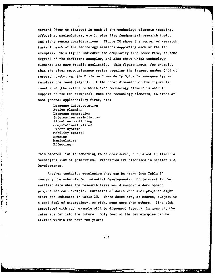
several (four to sixt een) in each of the technology elements (sensing,
effecting, manipulators, etc.), plus five fundamental research topics
and eight system considerations. Figure 20 shows the number of research
tasks in each of the technology elements supporting each of the ten
examples. This figure indicates the complexity (and hence risk, to some
degree) of the different examples, and also shows which technology
elements are more broadly applicable. This figure shows, for example,
that the river reconnaissance system requires the largest number (36) of
research tasks, and the Division Commander's Quick Data-Access System
requires the least (eight). If the other dimension of the figure is
considered (the extent to which each technology element is used in
support of the ten examples), then the technology elements, in order of
most general applicability first, are:
Language interpretationAction planningLanguage generationInformation assimilationSituation monitoringComputational visionExpert systemsMobility controlSensingManipulatorsEffecting.
This ordered list is something to be considered, but is not in itself a
meaningful list of priorities. Priorities are discussed in Section 5.2,
Developments.
Another tentative conclusion that can be drawn from Table 24
concerns the schedule for potential developments. Of interest Is the
earliest date when the research tasks would support a development
project for each example. Estimates of dates when such projects might
start are indicated in Table 25. These dates are, of course, subject to
r ~ a good deal of uncertainty, or risk, some more than others. (The risk
associated with each example will be discussed later.) In general, the
dates are far into the future. Only four of the ten examples can be
started within the next ten years:
231

Table 25
ESTIMATED DATE FOR DEVELOPMENT (6.3 and 6.4) STARTS
Division Commander's Quick Data-Access System 1985Brigade Mission-Planning Aid 1990Emergency Repair and Maintenance Advisor 1992Interrogation Support System 1995Tank Ammunition Handler 1996Mine Clearer 1990Tactical Threat Projection System 1998Safe-Return Controller 1998Light Fighting Sentry 2000River Reconnaissance System 2000
Of these, only the first one can be initiated very soon (1985). If the
evolutionary versions of the examples (discussed in Section 4.2) are
considered, eariier start dates are possible for most of the examples.
These are shown in Table 26. Here, developments of six more examples
could be started by 1990. One has already started, the version of the
Mine Clearer that is teleoperated and employs a line charge. The one-
armed Tank Ammunition Handler could also be started now, and the simple
database version of the Brigade Mission Planning Aid could be started in
1985.
Table 26
EARLY STARTS
Mine Clearer (teleoperated, line charge) 1984Tank Ammunition (one arm) handler 1984Division Comander's Quick Data-Access System 1985
Brigade Mission Planning Aid 1985Tank Ammunition (two arms) Handler 1989Emergency Repair and Maintenance Advisor (first vehicle) 1990
River Reconnaissance System (water only) 1990* Li-ht Fighting Sentry (first version) 1993
*2J
232
---* -

5.2. Developments
In this section, benefits, costs, and risks of the development and
life cycle of each example from Section 4.2 will be considered. These
factors are presented to provide useful background information for the
decisions that need to be made in the near term for Al/robotics R&D.
The ten examples were chosen to be illustrative, not the "best" of
the 100 Army application concepts that were noted in Section 4.1 and
described in Appendix A. The evaluation of the examples in Lhis section
applies only to the ten examples and does not have general implications
for the other 90 concepts.
To consider benefits, costs, and risks, some information developed
in Section 4.2 about distribution and some assumptions about schedules
are summarized in Table 27.
Table 27
DISTRIBUTION AND DATES FOR EXAMPLES
Year for CompletionExample No. of Units of Developments (6.4)
1 24 19892 72 19943 67,400 19964 22 20005 840 20026 44 19967 24 20038 1,000 20069 10,200 200710 66 2007
5.2.1. Benefits
The application categories were ranked according to their estimated
contributions to combat effectiveness. Th~s yielded the following list
of applcation categories with highest priority (most benefit) first:
233

WeaponsInformation collectorsPlanning and monitoring aidsSituation assessment systemsSupport systemsHuman/equipment lnterface aidsHandling support systemsSystem controllersExpert advisorsData assimilation and access aids.
Based on this ranking, the ten examples would have the following
ranking:
Light Fighting SentryRiver Reconnaissance SystemBrigade Mission Planning AidTactical Threat Projection SystemDivision Commander's Quick Data-Access SystemMine ClearerTank Ammunition Handler
Safe-Return ControllerEmergency Repair and Maintenance AdvisorInterrogation Support System.
Another, more methodical estimate of the relative benefits of each
of the ten examples was also developed. Benefits, as considered here,
are intended to be a measure of the contribution to combat effectiveness
of each example, assuming that it were developed to the full capability
described previously. Each example can be thought of as multiplying the
total Army combat effectiveness by some factor, just as the quality of
command and control is believed to provide an effective force
multiplier. Ideally, a quantitative factor, or multiplier, would be
desired. For example, if quantitative force multipliers were known for
helicopters and robot sentries, then the decisions that need to be made
about R&D for robot sentries would be much easier. Unfortunately, the
complexities of estimating overall combat effectiveness make such
factors unattainable, at least in the context of this study.
In estimating the relative benefits of the ten examples, the full
capability of each example was assumed, and, in addition, the examples
are assumed to be fully distributed. In the case of the robot sentry,
234
• " - ,, . i = - . : '" .... . .. ':ll' ' ] '
"- " , ... -" .... ," -

for example, this full distribution is one robot sentry per APC, or
10,200 robot sentries. The cost of the example and the risk associated
with it were not considered in estimating the relative benefits.
For each.example, a number of kinds of benefits were considered.
These included:
* Reduction of casualties (of personnel)
* Reduction of manpower spaces
* Replacement of manpower skills
* Contribution to continuous combat
Shortening of the time required* Conservation of resources
* C31 multiplier
* Contribution to maneuver
* Weapon effectiveness
* Contribution to survivability of forces
* Percentage of forces affected.
Points were estimated for the amount of each kind of benefit for each of
the ten examples. Estimates were prepared independently by a number of
persons with different military and technical backgrounds. The points
for the different kinds of benefits were added, and the tetals for the
different estimates were averaged to obtain a single benefits measure
for each example. The example estimated to have the greatest
contribut ion to combat effectiveness is listed first.
Mine ClearerLight Fighting SentryBrigade Mission Planning AidEmergency Repair and Maintenance AdvisorRiver Reconnaissance SystemTactical Threat Projection SystemTank Ammunition HandlerSafe-Return ControllerDivibiun Commander's Quick Data-Accpss System
2 Interrogation Support System.
If the two benefit rankings are combined, the first based on
consideration of application categories and the second based on
consideration of the examples, the following ranking is obtained:
235

Light Fighting SentryBrigade Mission Planning AidMine ClearerRiver Reconnaissance SystemTactical Threat Projection SystemEmergency Repair and Maintenance AdvisorTank Ammunition HandlerDivision Commander's Quick Data-Access SystemSafe-Return ControllerInterrogation Support System.
This relative ranking cannot be considered quantitative, but does
give an approximate measure of relative benefits of the ten examples for
the purpose of evaluating the research and development that supports
them.
5.2.2. Costs
The estimated life-cycle costs of the ten concepts are presented
here. These include the development (6.3 and 6.4) costs, investment
costs (procurement, initial training, etc.), and operations and support
costs required to equip a 24-division Army with each of the ten
conceptual systems for a period of ten years of operation.
All costs are presented in constant FY 1983 dollars.
The life-cycle cost estimates for the ten representative
AI/robotics concepts are shown in Table 28. Details of the cost
estimates and the costing methodology are provided in Appendix B of this
report.
236

Table 28
LIFE-CYCLE COST SUMMARY FOR TEN CONCEPTS
(costs in thousands of FY83 $)
No. of ProgramExample Example Units 6.3 and 10-Year TotalNumber Name Required 6.4 Investment Operation Life-
to R&D Cost and CycleEquip 24 Cost Support Cost
Divisions Costs
1 Division 24 2,674 5,424 13,440 21,538Commander's
Quick Data-Access System
2 Brigade 72 2,350 12,312 61,200 75,862MissionPlanningAid
3 Emergency 67,400 1,950 4,246,200 2,696,000 6,943,950Repair andMaintenanceAdvisor
4 Interro- 22 2,106 2,640 41,140 45,886eationSupportSystem
5 Tank 840 4,350 393,960 327,600 725,910AmmunitionHandler
6 Mine 44 6,192 32,252 22,880 61,324Clearer
7 Tactical 24 2,922 4,488 11,040 18,450ThreatProjectionSystem
8 Safe-Return 1,000 5,824 420,000 330,000 755,824Controller
237
_V 11

9 Sentry 10,200 6,134 4,743,000 2,754,000 7,503,134
10 River 66 5,828 28,908 73,260 107,996Reconnais-sance System
5.2.3. Risks
A similar subjective estimate of risks was developed for the
examples. Questions considered in assessing the risk of each example
are:
Can the technical goals be achieved?Is the estimated cost of R&D sufficient?Is the time allowed for R&D sufficient?Will alternate (non-Al/robotics) approaches be found that are
better?Will the need continue?
The estimate yielded the following list, with the example having the
least risk at the head of the list.
Division Commander's Quick Data-Access SystemMi-e ClearerEmergency Repair and Maintenance AdvisorBrigade Mission Planning AidTank Ammunition HandlerInterrogation Support SystemBrigade Mission Planning AidSafe-Return ControllerLight Fighting SentryRiver Reconnaissance System
Again, this relative ranking cannot be considered quantitative, but
does give an approximate measure of relative risks.
5.2.4. Benefit, Cost, and Risk Summary
,. j The benefits, costs, and risks of the ten examples are summarized
in Table 29.
238

Table 29
SUMMARY OF BENEFITS, COSTS, AND RISKS
BENEFITS
High Medium Low
Light Fighting Sentry River Reconnaissance Division Commander'sSystem Quick Data-Access
Brigade Mission Tactical Threat SystemPlanning Aid Projection System Safe-Return Controller
Mine Clearer Emergency Repair and Interrogation SupportMaintenance Advisor SystemTank Ammunition Handler
COSTS
High Medium Low
Light Fighting Sentry Safe-Return Controller River ReconnaissanceSystem
Emergency Repair and Tank Ammunition Brigade MissionMaintenance Advisor System Planning Aid
Mine ClearerInterrogation SupportSystem
Division Commander'sQuick Data-AccessSystem
Tactical Threatprojection system
RISKS
High Medium Low
River Reconnaissance Safe-Return Controller Tank Ammunition HandlerSystem
Light Fighting Sentry Tactical Threat Brigade MissionProjection System Planning AidInterrogation Support Emergency Repair and
. System MaintenanceMine ClearerDivision Commander's
- Quick Data-AccessSystem
239
..

In the case of the high-benefit examples, two, the Mine Clearer and
Brigade Mission Planning Aid, are both low cost and low risk. The Light
Fighting Sentry is high cost and high risk.
In the case of the medium benefit examples, two, the Tactical
Threat Projection System and the Interrogation Support System are low
cost and medium risk, whereas the River Reconnaissance System is low
cost and high risk. The Tank Ammunition Handler is medium cost and low
risk and the Emergency Repair and Maintenance Advisor is high cost and
low risk.
In the case of the low benefit examples, the Division Commander's
Quick Data-Access System is low cost and low risk, whereas the Safe-
Return Controller is medium cost and medium risk.
5.2.5. Early Starts
In addition to the benefits, costs, and risks, the estimated start
dates for the examples are also significant. The examples and their
evolutionary versions with starting dates before 1990 are:
1 Mine Clearer (teleoperated, line charge) 19842 Tank Ammunition Handler (one arm) 19843 Brigade Mission Planning (simple database) 1985
4 Division Commander's Quick Data-Access System 19855 Tank Ammunition Handler (two arms) 1989
5.2.5.1. Mine Clearer
As already noted, the Mine Clearer appears to have high benefit,
low cost, and low risk. The version described as an example was
estimated to be ready for development about 1990. The Al/robotics
research required is primarily for mine sensing and navigation. Given
priority, the research tasks that support these functions might allow
development to start earlier than 1990. The research tasks that support
the Mine Clearer are:
240

S3MCI, 2, 4CVI-5IAIAPI, 2, 4, 6-8
Also, evolutionary versions of the Mine Clearer should be
considered. A teleoperated version that employs a line charge is
already being developed.
5.2.5.2. Brigade Mission Planning Aid
The Brigade Mission Planning Aid is also high benefit, low cost,
and low risk. The research to support the example was estimated to
allow development to start about 1990. Higher priority for the
supporting research could accelerate that date. The research tasks that
support this planning system, and others as well, are:
LG1-5LI1, 3-5IA2AP1-6
SMI, 3-5
Again, development of an evolutionary version, with a simple
database and limited capability, could be started with the present
technology base. Evolutionary versions of this example are especially
attractive because the capabilities can be improved through software
upgrades.
5.2.5.3. Tank Ammunition Handler
The Tank Ammunition Handler has medium benefit, medium cost, and
low risk. Development of the example, with three arms, was estimated to
start in 1996. This late date is on account of the time estimated for
research on the high-flexibility arm. The research that supports the
Tank Ammunition Handler is:
241
4

S2E2, 3M1-4L13, 5
The critical research tasks are for manipulation, and these could
be given higher priority. Two evolutionary versions were noted
previously, one with one arm and another with two arms. Development of
the one-arm version could be initiated with the present technology base.
5.2.5.4. Division Commander's Quick Data-Access System
Although the Division Commander's Quick. Data-Access System was
estimated to have low benefit, the capability it provides would be
useful in many other command and control settings. Also, it is low
cost, low risk, and the only state-of-the-art example. Its development
could be started now. Research that supports it can enhance the
performance of the system and other applications of the capability
through software upgrades. The research tasks are:
LGI-3LIl, 3-5IA2
These tasks also support the Brigade Mission Planning Aid.
5.2.6. Longer Range Developments
The Light Fighting Sentry was evaluated as high benefit, high cost,
and high risk. The functions of the Light Fighting Sentry supported by
research tasks include: mobility, navigation, identification of targets
and 1FF, planning, and monitoring, all functions useful and important
for other applications as well. Development of the Light FightingSentry was estimated to start about the year 2000. An evolutionary
* version, immobile and teleoperated, could be started sooner, about 1993.
The research required to support the future development of the Light
Fighting Sentry and other applications that require mobility,
242

navigation, identification of targets and IFF, planning, or monitoring
should have high priority in near-term research plans. These research
tasks are:
SI, 3ElMC 1-4LG2, 3CV2-7L13-5AP7, 8SMI, 6, 7
Many of these, e.g., those required for navigation, have already
been listed as required for one or more of the early-start developments
in Section 5.2.5.
Two medium-benefit examples, the Tactical Threat Projection System
and Interrogation Support System, were estimated to have low cost and
medium risk. Also, both are longer range, development of the Tactical
Threat Projection System estimated to start in 1998 and the
Interrogation Support System in 1995. Both depend on successful
research and the solution of difficult problems in Al for which little
experience exists. Evolutionary versions of these examples appear
unlikely. The research is longer range, but potentially important for
these examples and other applications.
wsThe River Reconnaissance System, another medium benefit example,
wsestimated to be low cost, high risk, and the longest range of all
the examples. Fortunately, many of the research tasks required for the
River Reconnaissance System are also required for other, higher priority
examples. The feasibility of the River Reconnaissance System and other
long-range applications can be determined more accurately in the futurerj ~ when the research required for the higher-priority examples is furtheralong.
The Emergency Repair and Maintenance Advisor and the Safe-Return
Controller, medium benefit and low benefit, respectively, are both
examples of expert systems, an advanced and fairly well understood
243

specialty in AI. However, both of these examples present difficult
problems, not well matched to the state-of-the-art in expert systems,
and the Emergency Repair and Maintenance Advisor, because of its wide
distribution, requires a large investment. Other expert-system
applications are probably better matched to the state-of-the-art and are
also important for Army comibat or combat support.
244

6. CONCLUSIONS
Al/robotics will significantly enhance the capabilities of the
Army.
A unified model of artificial intelligence (AI) and robotics is
appropriate for Army R&D plans in AI robotics. The major components of
this model include sensing, interpreting, reasoning, generating, and
effecting.
The number of potential applications of Al/robotics in Army combat
and combat support is large. One hundred concepts for such
applications, collected from a variety of sources, have been described
and incllded here.
The 100 concepts divide reasonably into ten categories of
applications, based primarily on combat and combat-support functions.
These categories are:
Human/equipment interface aidsPlanning and monitoring aids
Expert advisorsData assimilation and access aids
Handling support systemsSupport systemsSituation assessment systems
System controllersWeaponsInformation collectors
A detailed study of an exemplary concept from each of the
application categories revealed a number of gaps between current state-
of-the-art in Al/robotics and the technology required to realize the
application. These technology gaps, or research tasks, provide a basis
for a research plan that supports the development of the exemplary
concepts and other applications of Al/robotics in Army combat and combat
support.
245
&

The recommended research consists of fundamental research, specific
research tasks, and system considerations. Included in the research
plan for AT/robotics are five fundamental research topics, 97 specific
research tasks (in sensing, interpreting, reasoning, generating, and
effecting), and eight system considerations. In addition, research on
some supporting technologies is required.
The examples of applications of AT/robotics to Army combat and
combat support were choseni and described in detail to identify Lhe
research required to realize future applications of Al/robotics, not
necessarily to realize the specific applications. Most of the
recommended research tasks support multiple applications, and several
common system modules have been identified. These findings verify the
general approach taken here, i.e., the use of examples of applications
to motivate the research, even when the examples may not be the ones
eventually developed.
This study did not evaluate the 100 concepts for applications of
AT/robotics that were collected and described in this report, except for
a brief evaluation of ten examples. Additional study and evaluation of
all of these concepts are needed. Such studies are needed primarily todefine bettor objective applications of Al/robotics to Army combat and
combat support, and secondarily to improve the definition of the
research plan presented here.
The recommended research plan includes research to obtain
information required to make future decisions about resea--ch priorities
and application objectives.
Most potential applications will require advancement of the
technology base (6.1 and 6.2) before advanced development (6.3) of the
applications can be started. With the capabilities ascribed to the ten
examples, the study estimated that development could be started on only
four during the next ten years. Two examples would require deferment of
development until the year 2000.
246

However, early starts for development of Al/robotics applications
are possible if applications with less capability, evolutionary versions
of the objective applications, are developed. The study identified four
such candidate applications that could be developed now, without
advancement of the technology base. These candidate applications are:
Mine Clearer
Brigade Mission Planning AidTank Ammunition HandlerDivision Commander's Quick Data-Access System
These applications also rank favorably when benefits, costs, and
risks are considered. (In the case of the Mine Clearer, development of
a teleoperated version employing a line charge has already started.)
Successful future applications of Al/robotics will require the
inclusion of system considerations in research plans, such as
feasibility studies, development tools, system integration, and
modularity. Both hardware and software modules that would be common for
a number of applications appear to be possible. Much of the evolution
of Al/robotics systems should be possible by means of module
replacement, especially by the upgrading of software modules.
Countermeasures and counter-countermeasures should also be included
in the research plan as system considerations.
Although some of the examples that were studied are long range,
such as the Light Fighting Sentry and River Reconnaissance System, the
research that would make these examples possible Phould be supported
because it is addressed to important functions such as mobility,
navigation, and identification of targets, that will be vital for many
Army applicationq in the future.
247

7. RECOMMENPATIONS
The objective of the study reported here is an R&D plan in
Al/robotics for Army combat and combat support. This plan was discussed
in detail in Section 5 (Section 5.1--Technology Base; Section 5.2--
Development), and will not be repeated here, but it is the principal
recommendation of the report. It can be summarized as follows:
Technology Base
Fundamental research--5 ongoing tasksSpecific research tasks:
Sensing--6 tasksEffecting--5 tasksManipulators--4 tasksMobility control--7 tasksLanguage generation--10 tasksComputational vision--12 tasksLanguage interpretation--8 tasksInformation assimilation--6 tasksExpert systems--13 tasksAction planning--16 tasksSituation monitoring--lO tasksSupporting technologies--7 tasks
System considerations--8 tasks
Development
The report includes detailed descriptions of ten examples,
including the dates when advanced development could be initiated for
each, an analysis of benefits, costs, and risks for each, and estimated
dates for completion of prototype development. However, these specific
examples, in general, are not recommended for development. Their
development is discussed to motivate the research plan. Deciding what
to develop, and when, will require additional study. Nevertheless, some
of the examples appear to be promising enough to warrant special
attention as candidates for development, since development of
249

evolutionary versions of them could be initiated with little or no
advancement of the present state-of-the-art. These are:
Mine ClearerBrigade Mission Planning AidTank Ammunition HandlerDivision Commander's Quick Data-Access System
Development of the Mine Clearer (a teleoperated version employing a
line charge) has already been started by the Army. Plans for it need to
be reviewed in the context of the Mine Clearer described in this report.
Research tasks that support the Mine Clearer, for navigation and for
mine location, should be given priority.
Research that supports the other three candid ate applications, for
which the development of evolutionary versions could be started now,
should receive special attention.
System considerations are also important and should be included in
the research plan, including system integration and modularity.
Hardware and software modules for AT/robotics applications could be used
to upgrade evolutionary versions and to support multiple applications.
250

BIBLIOGRAPHY
1--GENERAL
1982 Robotics Industry Directory, Robotics Industry Directory, La
Canada, California (1982).
Abraham, R. G., R. J. S. Stewart, L. Y. Shum, "State-of-the-Art in
Adaptable-Programmable Assembly Systems," Westinghouse R&D Center,
published by IFS Publications Ltd., 35-39 High Street, Kempston, Bedford
MK42 7BT, England.
Albus, J. S., "Brains, Behavior, and Robotics," BYTE Books,
Subsidiary of McGraw-Hill, Peterborough, New Hampshire (1981).
"Assembly Automation," five issues/year, $84.00/year, IFS
Publications Ltd., 35-39 High Street, Kempston, Bedford MK42 7BT,
England.
"Assembly Engineering," monthly, controlled circulation, Hitchcock
Publishing Company, P.O. Box 3001, Hitchcock Building, Wheaton,
Illinois 60187.
Barrow, H. G., "Artificial Intelligence: State of the Art,"
Technical Note 198, Artificial Intelligence Center, SRI International,
Menlo Park, California (October 1979).
Binford, T. 0., et al., "Exploratory Study of Computer Integrated
Assembly Systems," Progress Report 4, STAN-CS-76-568, Stanford
University (I August 1976 to 31 March 1977).
Binford, T. 0., Computer Integrated Assembly Systems," Proceedings,
NSF Grantees Conference, Stanford University (January 1981).
Brady, M. and R. L. Paul, eds., The International Journal of
Robotics Research, quarterly, $4 5/year, ISSN 078-3649, Cambridge,
Massachusetts, MIT Press Journals.
251

Brooks T. L., "Superman; a System for Supervisory Manipulation and
the Study of Human/Computer Interactions," ONR Contract No. N00014-77-
C-0256, master's thesis, Man-Machine Systems Laboratory, M.T.T.,
Cambridge, Massachusetts (1979).
Brown, D. R., "Recommendations for an AT Research Facility at
NASA/GSFC," Task 2 Report, Project 2203, SRI International, Menlo Park,
California (October 1981).
Bundy, A., Artificial Intelligence: An Introductory Course, North
Holland, New York (1978).
Computerized Robots, The State of the Art, Integrated Computer
Systems, Inc., Santa Monica California (September 1980).
Duda, R. 0., N. J. Nilsson, and B. Raphael, "State of Technology in
Artificial Intelligence," in Research Directions in Software Technology,
P. Wegner, ed., pp. 729:749, MIT Press, Cambridge, Massachusetts (1979).
Engelberger, J., Robotics in Practice, Management and Applications
of Industrial Robots, New York, AMACOM (division of American Management
Associations), 328 pp., $39.95 (1981).
Foley, H., "A Preliminary Survey of Artificial Intelligence
Machines," SIGART Newsletter, No. 72, pp. 21-28 (July 1980).
General Dynamics Corporation, "ICAM Robotics Applications Guide,"
Technical Report AFWAL-TR:80-4042, Vol. II, available (single copies
only) on written request to Materials Laboratory, Air Force Wright
Aeronautical Laboratories, Air Force Systems Command, Wright-Patterson
Air Force Base, Ohio 45433.
Goldman, R., "Recent Work with the AL System," Proceedings of the
5th International joint Conference on Artificial Intelligence, pp. 733-
735, Cambridge, Massachusetts (22-25 August 1977).
Hnatek, E. R., "Semiconductor Memory Update: DRAMS," Computer
Design, Vol. 21, No. 1, pp. 109-120 (January 1982).
"The Industrial Robot," quarterly, $84.00/year, IFS Publications
Ltd., 35-39 High Street, Kempston, Bedford MK42 7BT, England.
252

"Industrial Robots International," monthly, $12.00/copy, Technical
Insights, Inc., 158 Linwood Plaza, P.O. Box 1304, Fort Lee, New Jersey
07024.
Latombe, J.-C., and A. Lux, "Intellegence Artificielle et Robotique
Industrielle," Le Nouvel Automatisme, No. 6, pp. 37-44 (May 1979), and
No. 7, pp. 21-29 (June-July 1979).
Marshall, M., "LISP Computers go Commercial," Electronics, pp. 89-
90 (20 November 1980).
McCorduck, P., Machines Who Think, W. H. Freeman and Co., San
Francisco, California (1979).
Mujtaba, M. S., "Current Status of the AL Manipulator Programming
System," Proceedings Tenth International Symposium on Industrial
Robotics, Milan (1980).
Nitzan, D., "Robotic Automation at SRI," Proceedings of MIDCON/79,Chicago, Illinois (November 1979).
Nitzan, D., et al., "Machine Intelligence Research Applied to
Industrial Automation," National Science Foundation Grant DAR78-27128,
Robotics Department, SRI International, 333 Ravenswood Avenue, Menlo
Park, CA, 94025 (November, 1980).
Paul, R. L., Robot Manipulators, Mathematics, Programming, and
Control, Cambridge, Massachusetts, M.I.T. Press (1981).
Proceedings, International Conferences on Industrial Robot
Technology, 1st through 10th. IFS Publications Ltd., 35-39 High Street,
Kempston, Bedford MK42 7BT, England.
Reed, F., "The Robots are Coming, the Robots are Coming," Next,
Vol. 1, No. 2, pp. 30-39 (May/June 1980).
"Robotics Age," bimonthly, $15.00/year, Robotics Publishing
Corporation, 10049 Commerce Avenue, Tujunga, California 91042.
"Robotics Today," quarterly, $21.00/year, Robotics International of
S.M.E., One SME Drive, P.O. Box 930, Dearborn, Michigan 48128.
253
L~t _.. ' _ .. .. ... . _ 'I'
. _ -- m . .. .. . .01" r _ T...

Smith, D., and D. Miller, "Computing at the Speed of Light," New
Scientist, pp. 554-556 (February 21, 1980).
Society of Mechanical Engineers, "Catalog of Users and Suppliers of
Industrial Robots," available through Robotics International of SME.
Takase, K., "Skill of Intelligent Robot," IJCAI-79, Tokyo, Japan
(1979).
Taulbee, 0. E. and S. D. Conte, "Production and Employment of PhDs
in Computer Science," Communications of the ACM, Vol. 19, No. 6,
pp. 311-313 (June 1976).
Tesar, D., "Trip Report, Visits to Major Research Centers in
Robotics in Europe and Russia," Center for Intelligent Machines and
Robotics, Department of Mechanical Engineering, University of Florida,
Gainesville, Florida (1981).
Turing, A. M., "Intelligent machinery," in Machine Intelligence,
Vol. 5, B. Meltzer and D. Michie, eds., Edinburgh University Press,
Edinburgh, and American Elsevier, New York (1970). (Written in 1947,
but previously unpublished.)
Weintraub, P., "Raising the Robot's I.Q," Discover, Vol. 2, No. 6,
pp. 76-80 (June 1981).
"Why Can't a Computer be More Like a Man?," The Economist,
Vol. 282, No. 7219, pp. 77-81, (9 January 1982).
Winston, P. H., "The MIT Robot," in Machine Intelligence, Vol. 7,
B. Meltzer and D. Michie, eds., Edinburgh University Press, Edinburgh,
and American Elsevier Publishing Company, New York (1972).
Winston, P. H., Artificial Intelligence, Addison-Wesley, Reading
(1977).
Winston, P. H. and R. H. Brown, Artificial Intelligence: An MIT
Perspective, MIT Press, Cambridge, Massachusetts (1979).
. 2--SENSING & EFFECTING
254

Baker, H. H., and T. 0. Binford, "Depth from Edge and Intensity
Based Stereo," Proceedings, 7th International Joint Conference on
Artificial Intelligence, Vancouver, British Columbia (August 1981).
Binford, T. 0., "Survey of Model-Based Image Analysis Systems," The
International Journal of Robotics Research, Vol. 1, No. 1 (Spring 1982).
Boyle, D., "BETA: Basis for a New Sensor Sorter," International
Defense Review, pp. 1275-1276 (August 1978).
Dodd, G. G., and L. Rossol, eds., Computer Vision and Sensor-Based
Robots, Plenum Publishing Corporation, New York (1979).
Free, J., "New Eyes for Computers: Chips that See," Popular
Science, pp. 61-63 (January 1982).
Harmon, L. D., "Touch-Sensing Technology: A Review," Technical
Report MSR8O-03, Society of Manufacturing Engineers, Dearborn, Michigan
(1980).
Hillis, W. D., "Active Touch Sensing," A.I. Memo 629, Cambridge,
Massachusetts, M.I.T. Artificial Intelligence Laboratory (April 1981).
Kowel, S. T., "Beyond Optical Imagers: The DEFT Camera," Optical
Spectra, pp. 52-56 (July, 1980).
Mamon, G., et al., "Pulsed GaAs Laser Terrain Profiler," Applied
Optics, Vol. 17, No. 6, pp. 868-889 (15 March 1978).
Nitzan, D., "Assessment of Robotic Sensors," Proceedings, NSF
Robotics Research Workshop, Newport, Rhode Island (15-17 April 1980)
(reprints available from Robotics Department, SRI International, 333
Ravenswood Avenue, Menlo Park, California 94025).
Nitzan, D., A. E. Brain, and R. 0. Duda, "The Measurement and Use
of Registered Reflectance and Range Data in Scene Analysis," Proceedings
of the IEEE, Vol. 65, No. 2, pp. 206-220, (February 1977).
Photonics Spectra, Vol. 16, Issue 1, pp. 59-60 (January 1982).
"Sensor Review," quarterly, $84.00/year, IFS Publications Ltd., 35-
39 High Street, Kempston, Bedford MK42 7BT, England.
255
... ... ..... . ..

Stucki, P., ed., Advances in Digital Image Processing, Theory,
Application, Implementation, Plenum Publishing Corporation, New York
(1979).
Sundaram, G. S., "The Position Location Reporting System,"
International Defense Review, pp. 1297-1301 (October 1981).
"REMBASS: The US Army's New Battlefield Sensor System,"
International Defense Review, pp. 531-535 (April 1980).
"The USAF'S PLSS Program," International Defense Review, pp. 1440-
1441 (September 1979).
Teja, E. R., "Voice Input and Output," EDN (20 November 1979).
Tenenbaum, J. M., "Prospects for Industrial Vision," Robotics
Department, SRI International, Menlo Park, California (November 1978).
Trinkhaus, H. P., "METEX and FEREX: State-of-the-art Hand-held Mine
Detectors," International Defense Review, pp. 1482-1484 (September
1978).
3--MANIPULATION
Ambler, A.P.A., et al., "A Versatile System for Computer-Controlled
Assembly," Artificial Intelligence, Vol. 6, No. 2, pp. 129-156 (Summer1975).
Bejczy, A., "Sensors, Controls, and Man-Machine Interface for
Advanced Teleoperation," Science, M.I.T. Press, Vol. 208, No. 4450,
pp. 1327-35 (20 June 1980).
Bolles, R. C. and R. Paul, "The Use of Sensory Feedback in a
Programmable Assembly System," Memo CS-396, Computer Science Department,
Stanford University (October 1973).
Brady, M., and R. L. Paul, eds., Robot Motion, Planning and
* Control, Cambridge, Massachusetts, M.I.T. Press (1982).
Feldman, J., et al., "The Use of Vision and Manipulation to Solve
* the Instant Insanity Puzzle," Proceedings Second International Joint
Conference on Artificial Intelligence, pp. 359-364, London, England
(1971).
256
..........

Goldman, R., "Recent Work with the AL System," Proceedings, Fifth
International Joint Conference on Artificial Intelligence, pp. 733-735,
Cambridge, Massachusetts (22-25 August 1975). Intelligence Laboratory,
Stanford University.
Goldman, R. and S. MuJtaba, "AI User's Manual," Artificial
Intelligence Laboratory, Stanford University, third edition (December
1981).
Lozano-Perez, T., "The Design of a Mechanical Assembly System," AI-
TR-397, Massachusetts Institute of Technology, Cambridge, Massachusetts
(December 1976).
Salisbury, J. K. , "Articulated Hands: Force Control and Kinematic
Issues," The International Journal of Robotics Research, Vol. 1, No. 1
(Spring 1982).
4--LOCOMOTION
Bradley, C. D. , "Wheels Versus Tracks," Armor, pp. 24-29 (May-June
1981).
Dicker, R. J. L., "MIN -- The Italian Navy's Mine Disposal
Vehicle," International Defense Review, pp. 377-378 (March 1980).
Fincher, S. J., "The Control of a Remotely Piloted Helicopter," IEE
Colloquium on Control and Application of Remote Piloted Vehicles,
London, England (1-8 January 1980).
Heckman, P. J., Jr., "Free-Swimming Submersible Testbed (EAVE
WEST)," Technical Report 622, Naval Ocean Systems Center, San Diego,
California (15 September 1980).
Hirose, S., and Y. Umetani, "The Synthesis of Basic Motion
Regulator System for Quadrupedal Walking Vehicle and Its Experiments,"
(in Japanese) Transactions of the Society for Instrumentation and
Control Engineering, Vol. 16, No. 5, pp. 743-53 (October 1980).
O'Connor, A.J., "Air Cushion Vehicles," Armor, pp. 13-16 (January-
February 1979).
257

Ogorkiewicz, R. M., "Trends in Tank Technology," Armor, pp. 8-14
(July-August 1980).
Orin, D. E., "Supervisory Control of a Multilegged Robot," The
International Journal of Robotics Research, Vol. 1, No. I (Spring 1982).
Simpkin, Br R., "Closing the Survivability Gap," Armor, pp. 19-24
(November-December 1981).
5--NATURAL LANGUAGE
Appelt, D. E., "Planning Natural Language Utterances to Satisfy
Multiple Coals," Ph.D. Dissertation, Stanford University (December
1981).
Gnanamgari, S., "Providing Automatic Graphic Displays through
Defaults," Proceedings of the Third National Conference of Canadian
Society of Computational Studies of Intelligence (May 1980).
Grosz, B. G., "Research on Natural-Language Processing at SRI,"
Technical Note 257, Artificial Intelligence Center, SRI International,
Menlo Park, California (November 1981).
Haas, N. and G. G. Hendrix, "Machine Learning for Information
Management," Technical Note 252, SRI International, Menlo Park,
California (1981).
Harris, L. R., "ROBOT: A High Performance Natural Language
Processor for Data Base Query," Proceedings of the Fifth International
Joint Conference on Artificial Intelligence, NIT, Cambridge,
Massachusetts, pp. 903-904 (1977).
Hendrix, G. G., "LIFER: A Natural Language Interface Facility,"
Technical Note 135, Artificial Intelligence Center, SRI international,
Menlo Park, California (1977).
Hendrix, G. G., E. D. Sacerdoti, "Natural-Language Processing Part
One: The Field in Perspective," Technical Note 237, Artificial
Intelligence Center, SRI International, Menlo Park, California (1981).
Herot, C. F., G. A. Wilson, "Semantics Versus Graphics--To Show or
Not to Show," Technical Report CCA-80-09, Computer Corpuration of
America (March 1980).
258

Lowerre, B. T., "The HARPY Speech Recognition System," PhD Thesis
and Technical Report, Computer Science Department, Carnegie-Mellon
University, Pittsburgh, Pennsylvania (1976).
Moore, R. C., "Practical Natural-Language Processing by Computer,"
Technical Note 251, Artificial Intelligence Center, SRI International,
Menlo Park, California (1981).
Robinson, A. E., et al., "Interpreting Natural-Language Utterances
in Dialogs About Tasks," Artificial Intelligence Center, Technical Note
210, SRI International, Menlo Park, California (March 1980).
Winograd, T., "Procedures as Representation for Data in a Computer
Program for Understanding Natural Language," Technical Report Al TR-17,
MIT, Cambridge, Massachusetts (1971). Also published as Understanding
Natural Language, Academic Press, New York, New York (1972).
Woods, W. A., R. M. Kaplan, and B. Nash-Webber, "The Lunar Sciences
Natural Language System: Final Report," Report No. 2378, Bolt, Beranek,
and Newman, Inc., Cambridge, Massachusetts (1972).
6--PLANNING
Daniels, L., "Planning: Modifying Non-Linear Plans," DAI Working
Paper 24, University of Edinburgh (December 1977).
Fikes, R. E., "Monitored Execution of Robot Plans Produced by
STRIPS," Proceedings of the IFIP Congress, Ljubljana, Yugoslavia (1971).
Fikes, R. E., P. E. Hart, N. J. Nilsson, "Learning and Executing
Generalized Robot Plans," Artificial Intelligence, Vol. 3, No. 4, pp.
251-288 (Winter 1972).
Hayes-Roth, B., et al., "Modeling Planning as an Incremental,
Opportunistic Process," Proceedings IJCAI--79, pp. 375-383, Tokyo,
Japan (August 1979).
Hayes-Roth, B., et al., "Planners' Workbench: A Computer Aid to Re-
Planning," P-6688, The Rand Corporation, Santa Monica, California
(October 1981).
259

Nilsson, N. J., "A Hierarchical 'obot Planning and Execution
System," Artificial Intelligence Center Technical Note 76, SRI
International, Menlo Park, California (April 1973).
Robinson, A. E., and D. E. Wilkins, "Representing Knowledge in an
Interactive Planner," Proceedings of the First Annual Conference of the
AAAI, pp. 148--150, Stanford University (August 1980).
Robinson, A. E., "SPOT: The Application of Artificial Intelligence
to Planning Aircraft Movement on a Carrier," (in preparation).
Rosenschein, S. J., "Plan Synthesis: A Logical Perspective,"
Proceedings of 1981 International Joint Conference on Artificial
Intelligence, Vancouver, British Columbia (25-28 August 1981).
Sacerdoti, E., "A Structure for Plans and Behavior," Elsevier,
North-Holland, New York (1977).
Stefik, M., Planning With Constraints," Report STAN-CS-80-784,
Computer Science Department, Stanford University, Ph.D. Dissertation
(1980).
Tate, A., "Generating Project Networks," Proceedings IJCAI--77,
pp. 888-893, Cambridge, Massachusetts (August 1977).
Vere, S., "Planning in Time: Windows and Durations for Activities
and Goals," Jet Propulsion Laboratory, Pasadena, California (November
1981).
Wilkins, D. E., and A. E. Robinson, "An Interactive Planning
System," Artificial Intelligence Center, Technical Note 245, SRI
International, Menlo Park, California (July, 1981).
7--EXPERT SYSTEMS
Bennett, J. S., C. R. Hollander, "Dart: An Expert System for
Computer Fault Diagnosis," Proceedings Seventh International Joint
Conference on Artificial Intelligence, Vancouver, Canada (August 1981).
Duda, R. 0., et al., "Development of the PROSPECTOR Consultation
System for Mineral Exploration," Final Report, SRI Projects 5821 and
6415, SRr international, Menlo Park, California (October 1978).
260
6wr---~- 9-

Duda, R. 0., J. G. Gaschnig, "Knowledge-Based Expert Systems Come
of Age," BYTE Publications Inc., Fairchild Camera and Instrument Corp.,
Palo Alto, California, and SRI International, Menlo Park, California
(September 1981).
Feigenbaum, E. A., "The Art of Artificial Intelligence--Themes and
Case Studies of Knowledge Engineering," Proc. Conference FIPS, Vol. 47,
National Computer Conference, Anaheim, California (5-8 June 1978). Also
published in Proceedings of Fifth International Joint Conference on
Artificial Intelligence, MIT, Cambridge, Massachusetts, pp. 1014-1029
(1977).
Genesereth, M. R., "The Use of Hierarchical Design Models in the
Automated Diagnosis of Computer Systems," HPP-81-20, Stanford University
Heuristic Programming Project, Stanford University (December 1981).
Shortliffe, E. H., "Computer-Based Medical Consultations: MYCIN,"
Elsevier, New York (1976).
Webster, R. and L. Miner, "Expert systems, Programming Problem-
Solving", Technology/2, pp. 62-73 (January/February 1982).
Wilczynski, D., "Knowledge Acquisition in the Consul System,"
USC/Information Sciences Institute, Marina Del Rey, California.
8--REASONING
Brotsky, D., "Program Understanding Through Cliche Recognition,"
Artificial Intelligence Laboratory, Massachusetts Iastitute of
Technology, Cambridge, Massachusetts.
Brown, J. S., et al., "SOPHIE: A Sophisticated Instructional
Environment for Teaching Electronic Troubleshooting (an Example of CAI
in Al)," BBN Report No. 2790, Bolt, Beranek, and Newman, Inc.,
Cambridge, Massachusetts (March 1974).
Buchanan, B. G. and J. Lederberg, "The Heuristic DENDRAL Program
for Explaining Empirical Data," Proceedings IFIP Congress, Vol. 71,*
LJubljana, Yugoslavia (1971).
261
Now-- -,-,- -

Ejiri, M., et al., "An Intelligent Robot with Cognition and
Decision-Making Ability," Proceedings of the Second International Joint
Conference on Artificial Intelligence, London, England, pp. 350-358
(1971).
Garvey, T. D., J. D. Lowrance, M. A. Fischler, "An Inference
Technique for Integrating Knowledge from Disparate Sources," Proceedis
Seventh International Joint Conference on Artificial Intelligence,
pp. 319-325, Vancouver, Canada (August 1981).
Rich, C, "Inspection Methods in Programming," AI-TR-604,
Massachusetts Institute of Technology, Cambridge, Massachusetts (June
1981).
Sussman, G. J., "Electrical Design: A Problem for Artificial
Intelligence Research," Proceedings Fifth International Joint Conference
on Artificial Intelligence, Cambridge, Massachusetts, pp. 894-9000
(1977).
9--BASIC RESEARCH ISSUES
Hendrix, G., Encoding Knowledge in Partitioned Networks,
Associative Networks--The Representation and Use of Knowledge in
Computers, N.V. Findler, ed., Academic Press, New York, New York
(1979).
10--VISION
Agin, G. J., "An Experimental Vision System for Industrial
Application," Proceedings Fifth International Symposium on Industrial
Robots, TIT Research Institute, Chicago, Illinois (September 1975).
Agin, C. J., "Computer Vision Systems for Industrial Inspection and
Assembly," Computer Magazine, Carnegie-Mellon University, Pittsburgh,
Pennsylvania (May 1980).
Ballard, D. H. and J. Sklansky, "A Ladder-structured decision tree
for recognizing tumors in chest radiographs," IEEE Transaction on
Computing, Vol. C-25, No. 5, pp. 503-513 (May 1976).
262

Barrow, H. G., 3. M. Tenenbaum, "Recovering Intrinsic Scene
Characteristics from Images," in Computer Visual Systems, A. Hansen and
E. Riseman, eds., Academic Press (1978). Also published as Technical
Note 157, Artificial Intelligence Center, SRI International, Menlo Park,
California (April 1978).
Barrow, H. G., J. M. Tenenbaum, "Computational Vision," Proceedings
of the IEEE, Vol. 69, No. 5 (May 1981).
Bolles, R. C., "An Overview of Applications of Image Understanding
to Industrial Automation," Technical Note 242, Artificial Intelligence
Center, SRI International, Menlo Park, California (1981).
Duda, R. 0. and P. Hart, Pattern Classification and Scene
Analysis, John Wiley and Sons, New York (1973).
Fischler, M. A., "Image Understanding Research and Its Application
to Cartography and Computer-Based Analysis of Aerial Imagery,"
Semiannual Technical Report, Project 1009, SRI International, Menlo
Park, California (July 1980).
Fischler, M. A., "Image Understanding Research and Its Application
to Cartography and Computer-Based Analysis of Aerial Imagery," Second
and Third Semiannual Technical Reports, Project 1009, SRI International,Menlo Park, California (April 1981).
Gleason, G. J., and G. J. Agin, "A Modular Vision System for
Sensor-Controlled Manipulation and Inspection," Technical Note 178,
Artificial Intelligence Center, SRI International, Menlo Park,
California (1977). Also published in Proceedings of the Ninth
International Symposium on Industrial Robots, Washington, DC (March
1979).
P~orn, B.K.P., "Obtaining Shape from Shading Information," in The
Psychology of Computer Vision, P. H. Winston, ed., 115-15, McGraw-Hill,
New York, New York (1975).F; Li, C. C., A. M. Savol, and C. P. Fong, "An Improved Algorithm forthe Detection of Small, Rounded Pneunoconiosis Opacities in Chest X-
263

Rays," Proceedings IEEE Conference on Pattern Recognition and Image
Processing, Chicago, Illinois, pp. 390-395 (May 1978).
Marr, D., "Visual Information Processing: The Structure and
Creation of Visual Representations," Massachusetts Institute of
Technology, Cambridge, Massachusetts.
Tenenbaum, J. M., "Application of Image Understanding to
Cartography: A Survey of Relevant Research and Opportunities," Technical
Report on Project 8718, SRI International (December 1980).
Waltz, D. C., "Generating Semantic Descriptions from Drawings of
Scenes with Shadows," AI TR-271, Artificial Intelligence Laboratory,
MIT, Cambridge, Massachusetts (August 1972). Also published in The
Psychology of Computer Vision, P. H. Winston, ed., pp. 1-91, McGraw-Hill
Book Company, New York, New York (1975).
JI
264

Appendix A
APPLICATION CONCEPTS

Appendix A
APPLICATION CONCEPTS
This appendix contains descriptions of the 100 concepts for
applications of Al/robotics technology to Army combat and combat
support. The derivation of these concepts is described in Section 4.2.
The concepts are grouped for convenience in ten application categories
described in Section 4.4. The order of concepts and categories is
arbitrary; it does not imply anything regarding relative benefits to the
Army, or relative difficulty of development.
1. Human/Equipment Interface Aids
a. Speech Command Auditory Display System
This device would be an avionics component for use in Army
helicopters. Its purpose would be to reduce needs for visual checks of
instruments by pilots in situations where they mubt concentrate on
visual aspects or flying on target engagement. The device would provide
an auditory readout of selected instruments (such as altitude, air-
speed, rate of descent). The readout would be provided either in
response to specific voice query by the pilot or as a notification when
readings outside of pilot-preselected boundaries occurred.
b. Voice Helicopter Control System
This device would be a component for use in helicopters to reduce
the pilot workload by enabling the pilot to perform selected control
operations by voice. Emphasis would be on operation such as switch or
instrument settings, or weapon system employment that currently require
the pilot to move his hand or use his eyes. The device would be
interactive, conversing with the pilot as necessary to assure
understanding of instructions and confirming execution.
267
LMI
c. Scene Interpreter/Clarifier
The purpose of this device would be to aid the soldier during
periods of both normal and restricted/impaired visibility in the
identification of battlefield images or objects. It would be a module
that could be attached to, or used In conjunction with, inventory items
such as imaging devices. The Scene Interpreter/Clarifier would be able
to discern an object or image when It was partially obscured or
camouflaged. The soldier would be able to Isolate a field in which he
wanted to have an image identified, and the module would alert the
soldier to potential hazards/impending lethality if present in that
field.
d. Multi-Lingual Order Generator
This would be a device for use at brigade and higher headquarters
that would produce detailed orders to subordinate units based on input
decisions and guidance. Inpuls would be in the form of oral
instructions, graphic displays, and written material. Outputs would be
hard copy graphics and written instructions in one or more languages.
Outputs might also be provided in electronic digitized form for
automatic electronic transmission.
e. Division Comander's Quick Data-Access System
The Division Commander's Quick Data-Access System CQDAS) would be a
briefcase-sized device intended for -ersonal use of Division commanders
to quickly obtain information on the status of available resources and
limited other situation information from databases. It would include
voice and graphic interfaces and could be connected to data lines to
provide complete access to available division automated databases, or it
could retain key resource information for limited operation in an
isolated mode.
268

2. Planning and Monitoring Aids
a. Mission Execution Monitor
This concept covers computer software to aid division and higher
headquarters in monitoring progress on execution of operation plans.
The plan would have the form of an activity diagram (e.g., a PERT chart
or hierarchical goal structure). The program would keep track of goals
currently being worked on, current resource allocations, alternatives in
a plan that were still viable, etc. It would display various aspects of
the battle plan, warn of problems (such as units too reduced in strength
to carry out their next mission), and indicate when all resources for an
activity were available.
b. Signal Array Planner
This concept is for an AI planning system to support dynamic
planning and decision-making regarding signal arrays (antenna arrays).
The system would aid in planning the best signal configurations to
support changing command-center locations.
c. Weapon Selection Planner
This concept pertains to Al software that would be used in
selecting weapons for employment against identified targets. The
software could be incorporated in automated fire direction and control
systems. Based on information acquired about the target and known
information on the friendly ard enemy situation, the system would use
resource allocation and other olanning techniques to determine which
weapons to use and when to use them.
d. Missile Launch Planner/Controller
This system would be an interactive planning system designed to aid
in the planning and control of multiple nuclear/conventional missile
launches to support operations. The system would be used to plan
necessary movements of firing unit modes to provide the best target
269

coverage, timing of launches, and alternative fire plans. It would be
used to monitor execution and aid in rapidly identifying possible
corrective actions to unforeseen difficulties.
e. River-Crossing Planner
This Al planning system would be used to aid in the planning of
highly complex deliberate river-crossing operations at division and
higher levels. The planning aid would treat all aspects of the
operation including maneuver, fire support, and logistics. It would
also be used to monitor execution and plan corrective action as
unforeseen situations developed. Software and any necessary display
hardware would be incorporated in the automated C2 system of the
headquarters involved.
f. Covering Force Maneuver Planner
In defensive operations, maneuver of the covering force is a highly
complex operation that must be carefully planned and executed in a
timely manner. This AI planning system would be designed to assist in
planning and control of such operations. It would incorporate
consideration of such factors as the terrain to be defended based on
enemy action, displacement to other defensive/delaying positions,
possible enemy penetrations, and likely attrition. The system would be
used to monitor the developing situation and replan as circumstances
dictated.
g. ASP Layout Planner
The ASP Layout Planner would be an AI planning system to assist in
determining best layouts of ammunition support points. It would be a
portable computer-based device that interactively aided in the planning,
considering factors such as inventory, terrain, likely demand patterns,
safety factors, and likely receipts of shipments.
270

h. Brigade Mission Planning Aid
The purpose of the Brigade Mission Planning Aid is to provide rapid
mission planning and operations assistance to the Brigade Commander and
his key staff members in decision/planning/execution during the course
of a dynamic battlefield situation. The system would be designed as a
self-contained (except power supply) transportable module, suitable for
mounting in an APC or fixed facility when available.
i. Soldier's Movement Guide
The Soldier's Movement Guide would be a small portable system that
indicates both the immediate direction and overall route a soldier (or
small anit) should move in order to reach a pre-designated objective.
It would be used primarily for patrol operations. Prior to the
movement, it is used to interactively plan a route based on an internal
terrain database and input information on the objective and constraints
(such as time, enemy positions, and intermediate objectives). During
movement, it would be periodically consulted and interactively provided
position and situation updating information. It would warn, when
necessary, of potential obstacles and hazards to be encountered, and, if
deviation from the planned route were necessary, it would be used to
quickly plan an alternative route.
J. Nuclear Fire Planner
This AI planning system would be designed for use at Division and
Corps levels to aid in preparing nuclear fire plans. It would be
capable of considering mission requirements, nuclear target effects,
damage limitation constraints, available weapons, troop safety, and
collateral damage risks.
271

3. Expert Advisors
a. Emergency Repair and Maintenance Advisor
The Emergency Repair and Maintenance Advisor (ERMA) would be a
small module used by combat or combat-support vehicle crewmen to obtain
expert advice on possible ways to repair their equipment in emergency
situations. It would be a self-contained hand-held unit, incorporating
a microprocessor, input/output devices, and an expert system covering
repair possibilities.
b. Missile Launch Trouble Shooter
The Missile Launch Trouble Shooter (MLTS) would be a small computer
device containing an expert system to provide advice to PERSHING II
missile crews as an aid in overcoming system faults or failures. It
would be a modular component used with, and coupled to, the system
programmer test station. It would include a microprocessor, audio
input, both audio and CRT display output, and software representing the
best available trouble-shooting expertise.
c. Combat Vehicle Service and Survival Advisor
This portable device would provide advice to small units or vehicle
commanders regarding possible survival actions or sources of support in
their immediate vicinity. In addition to a terrain database, it would
contain expert systems to advise on possible locations of sources of
supply (civilian fuel, food, water) and to advise on evasion and escape
actions.
d. EOD Advisor
The EOD Advisor would be a portable device containing an expert
system to provide advice on safing/disarming/disposal procedures to EOD
personnel. The system would incorporate available expert knowledge on
foreign munitions as well as proven EOD approaches, techniques, and
safety measures including field expedients.
272
-~o ..- mm----

e. Water Finder
This concept would be a portable device that would provide advice
to soldiers on where to look for water in arid areas. It would
incorporate an expert system that could provide advice based on inputs
regarding terrain description, local plant and animal life, and recent
meteorological conditions.
4. Data Assimilation and Access Aids
a. Interrogation Support System
Intelligence units are tasked with an interrogation mission whose
success is largely dependent on the timeliness and accuracy of response
information. The Interrogation Support System (ISS) would be a portable
device designed to provide the trained human interrogator with a tool to
assist in and facilitate the rapid and thorough forward exploitation ot
POW/detainees for Essential Elements of Information (EEl).
b. C2 Database Query Language
A language designed for discourse with command and control
databases, this software component would be user-oriented and would
employ applicative-language techniques (as opposed to procedure-oriented
language techniques). The component, In conjunction with automated C2
systems, would simplify database access for humans.
c. Route Planning Aid
This would be a small, hand-held computer device. It would be used
by men on foot, tank commanders, helicopter pilots, etc. It would make
use of a terrain database to answer questions about proposed travel
routes, such as: What will the terrain look like at any point along the
route? Where will a particular type of vehicle be visible to the enemy?
Does the terrain prevent the enemy from advancing toward me? What is
the safest (fastest, etc.) route to an objective? It would accept
voice and manual entry, and would provide responses by graphic display.
273

d. Combat Vehicle C2
This device would be a computer display system designed as a
component for installation on combat vehicles. It would be designed to
provide graphic display of up-to-date infor-mation on the friendly
situation, terrain, and enemy targets to aid the vehicle commander in
effective maneuver and firing. The system would integrate and use all
available Inputs from other systems (such as maneuver elements, fire
support elements sensors, position locating system, navigation system)
and an internal terrain database to interactively display key
information as requested by the vehicle commander.
e. Imagery Interpretation Aid
This system would be able to assist units tasked with imagery
intelligence. Based on hard copy imagery, it would be able to
automatically register, identify targets of interest, determine
coordinates, and perform UTM coordinate conversions.
f. Adaptive Database Reconfiguration System
This concept encompasses techniques and software that could be
applied to databases to create an adaptive reconfigurable database
organization capable of restructuring itself to provide optimum
performance based on actual use.
g. Multi-Sensor Data Assimilator
This concept includes distributed AI computer software intended to
aid in the efficient assimilation of data from multipie sensors into a
database. It would Include processing of data at the sensor and at the
database location. At the sensor location, the system would eliminate
clutter, and recognize and select needed data to the database, thus
reducing communication needs. At the database location, it would deal
with conflicting data, maintain an up-to-date world picture, and
recognize and prioritize data gaps for sensor coverage.
274

5. Hading Supr Sytms
a. Artillery Loader
This system would be mounted in an ammunition supply vehicle;
designed to select appropriate rounds desired by a howitzer crew,
prepare them for firing by replacing the nose plug with a fuze, and
moving them to a rack on the howitzer for final fuze
setting/loading/firing by the crew.
b. Tank Ammunition Handler
The Tank Ammunition Handler is a robotic device that is mounted on
platforms used to carry tank ammunition. A 2-1/2 ton truck was chosen
for this concept. The device is composed of three robotic arms that
work in conjunction to remove ammunition from pallets and hand it to a
crewman inside the tank for final storage in racks. It performs the
operation of cutting bands, opening cannisters, removing the rounds and
* lifting/moving them to a position from which a single crewmember can
handle the final aspect of storage.
C. Tank Gun Loader
The Tank Gun Loader, a component built into a tank, would perform
the manual operations of selecting rounds and loading them into the tank
main gun. Based on voice instructions of the tank commander, it would
remove a round of the proper type from storage racks and load it. After
firing, It would remove spent cartridges from the breech. In the event
of misfires, it would be capable of executing standard recovery
procedures.
*d. Contaminated Clothing Handler
This would be a transportable robotic device for use at forward
Personnel Decontamination Stations (PDS). At the PDS, the device would
be used to collect discarded items of contaminated clothing and load
them into sealed containers for later movement to clothing
275
- . --

decontamination facilities. It could also be used in unloading and
handling contaminated clothing at rear laundry/decontamination/
impregnation facilities.
e. Contaminated Casualty Handler
The Contaminated Casualty Handler would be a transportable robotic
device that would be used at forward aid stations to remove contaminated
clothing and equipment from injured soldiers who are not capable of
helping themselves. The device would also inspect the injured soldier
for any remaining contaminated spots once clothing is removed and apply
decontaminant to affected skin areas. In the event that contamination
on or very near wounds was detected, the device would not attempt
decontaminatiorn, but would, instead, clearly mark the area and the
patient to warn medical personnel of the problem.
f. rargo Handler
The Cargo Handler would be a component installed on selected
general-purpose supply/ transport vehicles of combat units. It would be
a highly dexterous voice-controlled or teleoperated device that would
load/unload mixed supplies on the vehicle.
g. Multi-Purpose Manipulator
This would be a multi-purpose, transportable robotic system that
could be quickly programmed for reach, motion, and position to perform a
variety of heavy lifting, moving, and placement tasks in forward areas.
Examples of such tasks are: moving bridging sections, moving fuel drums,
and transferring ammunition.
h. Refueler
This would be a robotic device, mounted on existing or programmed
POL bulk delivery vehicles. It would be able to independently locate
fuel-filling points on a variety of vehicles, remove the closure,
dispense fuel and reclose the filling point.
276
Lman

i. Vehicle Recovery Aid
The Vehicle Recovery Aid would be a semi-autonomous robotic device
employed by the crew of a recovery vehicle to attach cables or other
devices to the object/vehicle they are attempting to recover. It would
be a highly mobile, maneuverable and dexterous system capable of ground
movement, climbing on vehicles, and operating in shallow water, mud, or
NBC contamination. It would be able to use simple tools to aid in
improvised connections.
J. Ammunition Handler
The Ammunition Handler would be a robotic arm device intended for
installation on ammunition supply vehicles. It would be capable of
loading ammunition onto the velicle in palletized or loose form, and of
unloading or transferring it to other vehicles.
k. Helicopter Missile/Rocket Reloader
This would be a transportable robotic device designed for use at
forward area refuel and rearm points. It would rapidly perform the
manual operations of selecting, preparing, picking up, moving, and
loading rockets or missiles onto helicopters.
1. Nuclear Munition Outloader
The Nuclear Munition Outloader would be a device designed to
rapidly perform lifting, moving, and storing tasks in the outload of
nuclear munitions from storage igloos to recovery vehicles. The devices
would be specifically programmable for the varying content,
configuration, and outloading plans of individual igloos. Their
programs could be rapidly modified by voice command, if necessary,
during an actual outloading. They would be stored in the igloos. In
order to perform periodic training, test, and checkout of the systems
without moving nuclear munitions, the devices would be periodically
moved and used in dummy facilities in outload exercises.
277
_____ ____ ____ ____ ________ ___ ___ ____ ___ ___ ____ ___~....-

6. Support Systems
a. Vehicle Decontaminator
The Vehicle Decontaminator, a spraying system, would be designed
for use with standard liquid decontaminants and existing or planned
decontaminant mixing/application devices to speed operations, operate at
higher pressures, and reduce personnel involvement. The system
employing robotic spray-painting technology, would have selectable
programs for different combat vehicles and would be capable of sensing
any deviation from standard configuration and modifying its contour
motion accordingly.
b. Armor Resupply and Service Vehicle
This vehicle would be designed to perform rapidly the functions of
resupply and servicing of tanks. It would store supplies of fuel,
ammunition, and other small items such as crew rations, light weapons
ammunition, and lubricants. Under general control of its operator, it
would perform automatic refueling using a robotic arm/manipulator. It
would incorporate a device similar to the Tank Amm,!nition Handler for
loading main-gun ammunition. Small supply items could also be handed to
a crewman inside the tank for storage.
c. Line Charge Laver
This system would be a teleoperated vehicle that could project and
detonate a line charge as a means of breaching minefields.
I. Semi-Autonomous Assault Raft
A remotely-piloted raft, this system would be capable of
transporting vehicles and personnel across water obstacles. One
operator, controlling many rafts from a protected near-shore position,
would provide general instructions on loading and unloading points,
speed, and route, and could, if necessary, corre-t these instructirns en
route. Detailed maneuvering and control along the route would be
278

performed by the system. The system would remember experiences cn the
first crossing and use them in planning and executing subsequent trips.
e. Air Robotic Platform
This aircraft, an autonomous air platform, would be canable of
carrying or mounting various light payloads depending on the desired
mission. Either by itself or as a component in other applications, it
would be capable of autonomous takeoff, landing, navigation, and flight
between specified end points. It would be a small system capable of
carrying payloads up to 100 pounds.
f. Ground Robotic Platform
This system would be an autonomous robotic platform, capable of
carrying or mounting various light payloads depending upon the desired
mission. It could also be used as a component that would provide
mobility in other applications. The platform would be capable of
autonomous navigation between specified points, as well as following
another vehicle. It would be a lightweight vehicle capable of carrying
payloads up to 500 pounds.
g. Combat Vehicle--Support Slave
This would be a semiautonomous or teleoperated device that could
perform light tasks on the outside of a combat vehicle under general
control of the crew inside the vehicle. Carried on the exterior of the
vehicle, it would be highly dexterous and capable of moving all over and
around the vehicle, and using simple tools. Examples of tasks it might
perform are: minor repair, cleaning of vision/sensor ports, limited
deconamination, searching for mines, or observing beyond visual
obstacles.
h. Combat Porter
A version of the Ground Robotic Platform, this system would be
configured for transporting mixed small cargo loads in forward areas.
279
* .4-.-
It could be used in hazardous environments to perform tasks such as
ammunition resupply, rations delivery, and casualty evacuation.
i. Mine Emplacer
The Mine Emplacer would autonomously emplace standard-pattern
minefields. Based on a plan provided by the user, it would dig probe-
sized holes, fuze and arm mines, and emplace and cover them; it would
also be capable of self-loading mines from a nearby supply point. It
would automatically mark the minefield boundaries in accordance with
standard practices and would produce a hard copy detailed map of the
actual emplacements.
j. Soldier-s Slave
This system would be designed to perform a variety of manipulative
labor tasks under the close supervision and control of a soldier. The
soldier would exercise control through voice commands, teleoperation,
or, when possible, using "show-and-tell" techniques. In hazarlous or
contaminated environments, voice commanis could be transmitted by radio
or wire. The system could perform tasks such as lighting, carrying,
digging, erecting or adjusting antennas, or performing minor
decontamination operations.
k. Reconnaissance Robot
This system would be similar to the Tactical Reconnaissance Robot,
but it would be specially equipped to perform engineer reconnaissance
functions. Based on mission orders, it would be able to detect and mark
minefields, examine bridge structures, and check trafficability of roads
or off-road routes. It would have a limited capability for emplacement
of explosive charges.
1. Remote Communication Relay
This autonomous, ground mobile system would be designed to provide
line-of-sight radio communication relay at a designated location between
280

separated units. It could be delivered to the general vicinity of the
relay point by ground or air delivery.
m. Adaptive Airborne Communication Relay
This system would be an autonomous aerial platform that would
adaptively position itself (and change its position) to act as a
communication relay. The system would recognize and adapt to
propagation medium changes, electronic countermeasures, and line-of-
sight restrictions.
n. Smoke Layer
A mobile platform equipped with smoke-generating capabilities, this
system would be capable of moving to prespecified positions and emitting
smoke on command. It could be used on flanks or forward of an attack
and would reposition itself, based on micrometeorological conditions and
observations of its emitted smoke, to maintain the desired smoke
pattern. Many of the units would be capable of operating cooperatively.
o. Infantry Precursor
The Infantry Precursor would be a semi-autonomous robotic point man
for the infantry squad. Its major functions would be to detect and
report any enemy presence. It would be capable of returning any enemy
fire it drew for a short period of time until the squad could further
develop the situation.
p. Armor Precursor
The Armor Pres'ursor, a semi-autonomous armored vehicle, would
operat at the head of an advancing armor unit. It would perform
observation and reporting functions, and reconnaissance by fire when
ire:ted. It would have a limited capability to detect mines.
4I
281
MOM. -------- f
q. CP Antenna Remoting System
The CP Antenna Remoting System would be a collection of Ground
Robotic Platforms configured to transport antenna components, and
manipulation robots such as the Soldier's Slave. These components would
be controlled by a central control unit operated by a soldier. The
system would be designed to erect and connect rapidly all antennas
involved with a major communication node (such as a Division
headquarters) at a site chosen for its propagation properties and remote
from the headquarters elements. In addition to erecting the antennas,
the system would be capable of rapidly laying wire connections to the
headquarters facilities (possibly distributed in more than one
location).
r. Man-Packed Portable Deception System
This system would simulate a qquad or platoon in the field, giving
as complete a "signature" as passible to the enemy. It would be abl, to
conduct 1FF, activate when necessary, and act ir an autonomous fashion.
That is to say, it could move tc a new position at an appropxiate time.
In addition to deception in conventional situations, this device would
have applications in unconventional warfare where a special forces team
would penetrate an area a:,d then "buy time" by using such a device.
s. EOD Assistant
The EOD Assistant, a semi-autonomous robot, with a basic
understanding of explosive ordnance disposal (EOD) procedures, would
perform specific procedures based on general instructions given bv EOD
personnel from a safe, remote position.
J t. Airborne Minefield Detection System
An autonomous airborne device designed to reconnoiter designated
areas for the existence of minefields, this system would employ a
platform such as the Air Robotic Platform and multiple sensors (such as
optical, TR, and electromagnetic). If mines weru detected during the
282

reconnaissance, it would automatically explore the extent of the
obstacle and report this information to the using unit.
u. Barrier Emplacement Aid
This system would be a robotic aid for barrier operations (other
than minefield emplacement), including the emplacement of barbed wire or
other anti-personnel obstacles, and placement/detonation of shaped
charges or explosive devices to create obstacles. It would be a semi-
autonomous device, similar to the Soldier's Slave, but would be
specifically equipped and optimized for these tasks.
v. Remote Adaptive Jamming System
This device would be able to detect, identify, and locate target
signals and decide which to Jam and when to jam based on a set of
standards, and inputs on the tactical situation. The system would
select Jamming frequencies and times to delay, confuse, and possibly
abort enemy operations. It would recognize and not interfere with
higher priority signal-intercept operations.
w. Mine Clearer
The Mine Clearer would be an autonomous vehicle designed to aid the
combined arms term in breaching minefields of all types. Equipped with
sensors and mine neutralizing devices, it would rapidly traverse mined
areas, avoiding mines if possible, neutralizing them if necessary, and
marking the resulting safe lanes.
7. Situation Assessment System
a. Brigade Situation Analyzer
jThis concept would be a computer software component intended to aid
the brigade commander and staff in rapidly developing or modifying their
estimate of the situation when mission orders are received. The system
would maintain a database of information on opposing forces, terrain,
283

and the brigades' strength and deployments. On receipt of orders,
information on the mission, weather, forces, adjacent unit missions, and
time constraints would be entered. The system would interactively
develop an estimate of the situation including analysis of the friendly
and enemy situation, mission, terrain, weather, and constraints. It
would also provide the commander and staff with assessments of courses
of action they proposed.
b. Artillery Movement Assessment System
This concept would be a software component for use in Division and
Corps headquarters as an aid in assessing the implications of
information on enemy artillery position, activities, and movements. The
system would consider this information along with knowledge of enemy
doctrine and tactics, recent battle events, and the current friendly :nd
enemy situation. It would produce interpretations of the meaning of
detected movements and predict likely movement times and places.
c. Tactical Threat Projection System
The Tactical Threat Projection System (TTPS) would be an AI
software component intended for use at Division and higher headquarters.
It would be integrated with other automated software and hardware
components of the Division headquarters. Based on continuous data
inputs on the tactical situation, the TTPS would be able to project and
isolate the most probable courses of action of enemy forces, and the
manner in which the threat could manifest itself.
d. Super Sextant
This device would be a briefcase-sized device carried on combat and
combat-support vehicles, or, if necessary, transported by a soldier. It
would use the best information it could obtain to provide the user with
an estimate of his current position. Through a combination of internal
sensors/communication links and interactive input by the user, it would
assess data from active and passive sources such as celestial
284

observation, positioning systems, and terrain observation, to estimate
its position, and associated uncertainty. The system might be used as a
component of other AI/robotics devices.
e. Chemical Hazard Warning Analyzer
This would be a component for use with NBC sensors that are capable
of providing spectral observation in the infrared, visible, or
ultraviolet bands. It would combine such data with internally stored
data on terrain, vegetation, and recently observed atmospheric/surface
properties in the area of operations. Based on spectroscopic analysis,
it would determine whether or not the sencor data implied a hazard. It
would be capable of recognizing suspected new contaminants in addition
to the normal repertoire of standard agents.
f. Deception Identification System
In Imitative Communications Deception (ICD), an enemy pretends to
be a friendly station, transmitting deceptive signals in order to either
disrupt operations with false information, or elicit information of
intelligence value. This system would be a device for analyzing and
assessing transmissions to identify likely ICD employment efforts. The
system would use both technical analysis of the signal, and comparison
of its information content with known factors to perform such
assessments.
8. System Controllers
a. Line-of-Sight Controller
The Line-of-Sight Controller would be a teleoperated device
incorporating a forward vision element, a small multi-purpose
manipulator, a communication link, and a viewing/operating remote
control element to be used in a safe position. It would be used by
soldiers tu operate line-of-sight weapons or other devIces from remote
concealed and safe positions.
285
b. Safe Return Controller
The Safe Return Controller would be an intelligent system that
would assume control of an Army helicopter or airplane when the pilof
became disabled. The aircraft would be stabilized, would be returned to
a predetermined safe altitude, and would be returned to a friendly
airfield. The controller could be overruled by the pilot until such
time as It again sensed pilot dysfunction. The system, an avionics
component, would use information from other aircraft instruments and
would employ any available autopilot system as an aid in implementing
the actions it might decide to take.
C. Fire Allocation and Control System
The Fire Allocation and Control System would be an autonomous
device capable of deciding on appropriate allocations of targets to
available weapons and issuing engagement instructions to such weapons.
Based on target information from different sources (including humans or
other Al/robotics devices), it would consider the situation, available
weapon capabilities, and constraints and engagement rules entered for
its particular current employment. It would then provide output signals
indicating engagement allocations to the system it controlled (including
allocation to individual soldiers or robots manning weapons).
d. 1FF Module
An Al-based module to handle Identification Friend/Foe (1FF) should
be an essential ingredient of many Al/robotics systems, as well as an
aid to control operation of nonautomated weapons. Although various
versions of the module would be appropriate for different applications,
a common approach could be taken. The use of multi-sensor information
inputs (such as visual, electromagnetic signatures, IR or UV
characteristics, verbal codes, etc.) should be one ingredient of the
1FF determination. In addition to the specific signature patterns used
in nont-Al systems, this module would also consider the current actions
of the object in question, and the context of the current situation in
286

which those actions occur. Output decisions could be either yes/no or
probabilistic in nature.
e. Copilot
The Copilot would be an Al/robotics system configured and designed
to substitute for a copilot in Army aircraft. It would be employed as a
copilot in combat situations when human copilots were not available.
Although its' abilities would be less than those of a human copilot, it
would be able to perform most copilot functions, including simple flight
maneuvers, weapons control, observation, safety activities, and
instrument/control observation and setting with some suitable degree of
skill. It would be capable of voice communication with the pilot.
f. Armor Hit Avoidance System
This system would integrate control of available sensors and hit-
avoidance devices or procedures on armor vehicles. It might use passive
or active sensors to detect threats, and passive or active
countermeasures (such as multi-spectral screening smoke) to avoid hits.
The system would integrate sensor information with knowledge of the
vehicles current situation to promptly recommend (or automatically
initiate) survival countermeasures or proced..ires.
g. Helicopter Automatic Target Acquisition System
The Helicopter Automatic Target Acquisition System would be an AI
software module designed to provide rapid sensor data processing and
decision functions. It would be integrated with advanced sensor/threat
warning components in Army helicopters. The system would perform multi-
sensor integration, IFF, and threat prioritization functions. It would
base its output recommen'itions (or automatic decisions) on specific
sensor information and knowledge of the aircraft's currenL situa*ion.
4
287
-* r'.

h. EW Equipment Controller
Intelligence units require that electronic equipment be monitored
particularly in regard to EW and intercept missions. This includes the
continuous monitoring of scopes (regardless of the environment), a 24-
hour-a-day tedious task, as an example. The EW Equipment Controller
would be a component with necessary electronic interfaces to perform
such monitoring tasks, and perform associated responsive equipment
control.
i. Communication Network Manager
This system would be a component of communications systems. Tt
applies Al techniques to network management functions such as routing,
connectivity assessment, user authentication, and overall system
control.
J. Adaptive EW Control System
This system would be a central component used to adaptively control
the EW assets at division or higher level. Based on EW oupport plans,
the system would use existing and planned sensors to intercept, locate,
and identify enemy electronic emissions. Once interception was
accomplished, it would make target decisions based on the current
overall situation, such as whether to continue intercept, jam or employ
ICD. The decision would involve any desired level of human
participation. Based on the decisions the system would provide
appropriate control instructions to other EW systems designed to
accomplish the actions involved.
k. Target Acquisition and Homing Device
A small component for integration in smart (brilliant) munitions,
this device would apply Al techniques to the processing of inputs from
one or more on-board sensors. It would be able to identify targets of
the desired type in an area and provide sensor control signals and
homing signals for terminal guidance. It would incorporate an 1FF
288

module and would allow for imperfect sensor information arising from
factors such as smoke, camouflage, or electronic countermeasures.
1. Target Acquisition/Allocation System
This concept would provide an AI-based component for use in
automating the target-acquisition and fire-control functions of weapon
systems or other AT/robotics devices. Employing available sensors, it
would locate and identify targets of the types specified in its
instructions and would provide sensor control to optimally support this
process. It would perform the 1FF function and employ AI planning
techniques to create engagement plans best suited to the overall goals
of the current operation. Consistent with these plans, it would
allocate the targets to weapons for engagement. It would continuously
monitor execution and modify plans as new targets/threats emerged.
9. Weapons
a. Tears/Demons
Tank Effectiveness Augmentation by Remote Subsystems (TEARS) is a
concept that has been studied extensively by RAND Corporation. This
particular application involves augmenting a tank's basic capabilities
with one (or more) small semiautonomous mobile subsystem equipped with
sensors and an anti-tank weapon (DEMONS). The DEMONS would be
controlled from the tank, but data link requirements would be curtailed
by allowing some degree of autonomy in the DEMONS operation.
b. Light Fighting Sentry
The Light Fighting Sentry would be a device that could augment the
front line combat unit by providing sentry functions. It would carry
sensors and weapons and would be armed with a 7.62 mm rifle and a
grenade launcher (such as the M 79). Its primary missio.i would be that
of providing sentry-type functions such as warning, overwatch, or
covering of obstacles. It would have the capability to engage enemy
troops for a short period. In the context of the air-land battle 2000,
289

the Light Fighting Sentry could aid in providing 360-degree sentry
functions to the independent combat team.
c. Heavy Fighting Sentry
The Heavy Fighting Sentry would be conceptually similar to the
Light Fighting Sentry; however, it would be equipped with appropriate
sensors and weapons to engage enemy armor as well as light weapons for
close-in self defense against troops. Emplaced during defensive
operations overwatching a likely enemy avenue of approach, it would be
trained to occupy several firing positions. Upon sensing enemy armor
targets, it would occupy the most effective position and engage the
target. During engagement, it might change its position as necessary.
d. Close Air Defense Sentry
The Close Air Defense Sentry would be a system designed to employ
light anti-aircraft weapons such as the REDEYE or STINGER automatically
against enemy fixed-wing aircraft or helicopters. It might be emplaced
on a vehicle during movement or on a position suitable for giod aerial
observation when stationary. It could be led to its desired position by
a soldier and instructed on appropriate observation/engagement sectors.
It would incorporate necessary sensors and an 1FF module to allow
automatic target acquisition and engagement.
e. Infantry Robotic Grenade
The Infantry Robotic Grenade would be a munition similar In size
and function to a CLAYMORE mine but designed for use by the infantryman,
primarily in the offense. Baseli on brief instructions from the soldier,
it would move rapidly on the ground, autonomously planning its route to
a designated point, and then would detonate its directed, fragmentation
payload.
290

f. Homin.& Tank Killer
The Homing Tank Killer would be a shaped-charge munition designed
for employment by the infantryman in close-in defensc against advancing
enemy armor. Based on brief instructions from the soldier on the
general direction and nature of the target, it would autonomously plan a
route to engage the advancing tank. Tt would move rapidly along this
ground route, employing a combination of sensors to identify and home on
the target. When it reached the target, it would project itself onto
the tank in an appropriate position and detonate its shaped charge. It
would incorporate a delayed, self-activating mode of operation so that a
collection of the munitions could be left to autonomously guard an
avenue of approach well forward of the defensive position.
10. Information Collectors
a. River Reconnaissance System
The River Reconnaissance System, a man-portable robotic device,
would be used for reconnaissance of water obstacles; it would obtain
updated, detailed information on bank conditions, bottom conditions,
depths, current profiles, and submerged obstacles in support of planning
for hasty or deliberate crossing operations. In offensive situations,
it would collect the information needed to select crossing sites and
plan crossings which might employ fording vehicles, assault bcats, rafts
or bridges. In defensive situations, it would provide similar
information for use in ,ssessing feasibility of enemy crossings and
avenues of approach.
b. NBC Reconnaissance Robot
The NBC Reconnaissance Robot would be an autcnomous system designed
to perform the function of detecting, identifying, mapping, reporting,
marking, and, (if necessary), sampling surface nuclear, biological or
chemical contamination. The robot, incorporating both remote and noint
NBC sensors, would operate in contiminated areas, detect self-
contamination, and, upon leaving the areas, would decontaminate itself.
291

AD-A18 297 SRI INTERNATIONAL MENLO PARK CA F/8 6/4
R&D PLAN FOR ARMY APPLICATIONS OF Al/ROBOTICS.(U)
MAY 82 D R BROWN, D V FOWLER, 0 J FRIE OAAK-681-C-0250
NCLASSIFIED ETL-0296 NL
; mhhhhhh Ii1mhIIIIIIIIIIIlEEEEIIIII

c. Aerial Observer/Designator
This system would be a semi-autonomous air vehicle that could
observe enemy activity, detect and identify targets, and, on command,
designate targets with a laser. It would be operated by a person from a
concealed position.
The operator would provide instructions on the general area to be
observed and a permissible flight envelope for the type of targets
sought. Within those constraints, the system would plan and perform its
own flight maneuvers to cover the desired area. When a target was
acquired, the system would notify the operator and designate/illuminate
the target on command for attack with homing munitions.
d. Ground Observer/Designator
Ground Observer/Designator is a semi-autonomous system designed to
observe a specified area, alert the user when targets of a specified
nature appear, and, on command, designate/illuminate the target with a
laser for attack with homing munitions. The system can independently
alter its position among preselected alternates to enhance its
observation capability and survivability. It normally operates in a
passive mode, and transmits a minimum amount of target information only
when a target is acquired.
e. Remote Scene Analyzer
This device would be a component for use with imaging sensors such
as night-vision devices. Used to analyze the scene otserved by the
sensor, identify objects in predetermined classes, although they might
be partially obscured, and locate the object in terms of its own
position, it could operate in either a direct or remote mode; in the
direct mode, it would highlight/enhance and identify the object in a
.I visual display for the user. In a remote mode, it would either perform
this same function or simply transmit limited data on the object and its
location, depending on the user's desires.
292
f. EW Sentry
This system, a semi-autonomous mobile device equipped with a suite
of EW sensors, would be capable of movement to or between predesignated
position. where its sensors could be most effectively employed. It
would monitor the designated area for any active EW employment
indication and transmit positive identification information to its user.
g. NBC Sentry
A mobile device, the NBC Sentry would employ a combination of
remote and point NBC detection devices to detect vapor or aerosol NBC
contamination, and to automatically transmit warnings to threatened
units. It would incorporate a local micro-meteorological measurement
and prediction system and a terrain data base. It would select for and
adjust its observation position based on observed and predicted
conditions in order to provide area coverage and could operate in
cooperation with one or more other similar units.
h. Wire Tapper
This device would find enemy wire communication lines, attach
itself in a manner suitable for intercepting traffic on the lines, and
transmit the intercepted traffic to the using unit. A small rugged
device, it could be dispersed behind enemy lines by artillery, rockets,
mortars, or aircraft dispensers. It would search for wires employing a
combination of electromagnetic, visual and metal sensors. It would
include an optional feature to cut detected lines.
1. Street Walker Scout
] This system for scouting ahead of Army units fighting in built-up
-. 3 areas would be semi-autonomous, with some control exercised over a wire
or other data link. It would be capable of operating up to one block
forward of the using unit. In addition to transmitting information from
its sensors, it would automatically seek to locate any source of enemy
weapons fire.
293

j. Approach Sentry
This system would be designed to operate as an unattended sentry in
forward or rear areas, its primary function being to detect and report
the presence of personnel or vehicles within its assigned observation
area. It would be capable of observing from fixed positions or along a
designated patrol route. It would include optional features that would
actively attempt to identify any personnel or vehicles detected.
k. Leach Armor Marker
This device would be a small, low-cost sensor/designator, designed
for scattering on likely armor approaches. It would detect and identify
any targets of the pre-designated type in its immediate vicinity. It
would then attach itself firmly to the target and emit an appropriate
signal for homing munitions.
1. Multi-Purpose Sensor Emplacer
This device would be a highly mobile carrier, with a manipulating
arm, that would be used to transport a wide variety of sensors to remote
positions in the friendly area or behind enemy lines. It would be
capable of autonomous route planning navigation, movement and
emplacement actions based on brief instructions on objectives from the
user.
m. Tactical Reconnaissance Robot
This system would be capable of performing autonomous
reconnaissance missions behind enemy lines and planning its detailed
activities en route and at specified objectives in order to accomplish
its mission. Capabilities would include observation, small object
collection, and reconnaissance by fire.
n. Soldier's Auxiliary Eye
The Soldier's Auxiliary Eye would be a small, portable imaging
sensor device that would operate selectably in either the visible or the
IR bands. It would automatically convert IR-image information to
visible displays which could be readily interpreted by the soldier. The
device would be remotely controlled and could move short distances on
the ground in the vicinity of its operator to reach suitable observation
positions.
294

Appendix 3
DETAILS OF COST ANALYSIS

Appendix B
DETAILS OF COST ANALYSES
1. Costing Methodology
The representative Al/robotics systems, for which life-cycle cost
estimates were generated, were conceptual in nature; the scope of the
project did not permit the project team to complete detailed designs for
each system, which would have included quantitative, reliable data on
system size, weight, power requirements, power output, reliability,
maintainability, etc. Consequently, the cost estimates had to be
generated with substantial use of qualitative considerations and
engineering judgment. In some cases a system element could be
considered analogous to an item in the current state-of-the-art; for
example, the articulated legs of the light-fighting sentries resemble
the industrial robotic arms that are currently available "off-the-shelf"
from many manufacturers. In this case, the cost of a sentry leg was
assumed to be the same as the cost of a robotic arm, less its
programming system (which would be replaced by the sentry's robust
computer).
Each of the ten concepts included a high-capacity computer, and
this element sas, in most cases, a substantial contributor to the total
cost of the system; however, it was difficult to predict accurately the
costs of these computers because we were looking at a time-frame some
years into the future, and the current explosively rapid developments in
solid-state technology are very difficult to extrapolate. Essentially,
our concepts envisioned miniaturized computers of high capacity,
equivalent to the current DEC VAX-11/780. The VAX currently costs about
$140,000 to acquire, and it fills a small room. Our concepts envision
computers of similar capacity that might fit into a small device like
the manr-portable River Reconnaissance System. In the cost analysis we
297
i a E

estimated that this super-miniaturized VAX might cost up to $20,000 to
acquire, and each concept that required a high-capacity computer was
therefore charged $20,000 for its computer. Some of the concepts which
presented a lower-capacity computation requirement were charged lesser
amounts on the basis of our engineering judgment; for example, $10,000was charged for the computer in the tr~nk ammunition handler.
The coats of operations and maintenance personnel were based on the
assumption that all such personnel were at the E-4 grade level.
To help in the cost analysis, we initiated a mail survey to some 85
current manufacturers of AI and robotics systems, and received
approximately a 60 percent response.
In assessing the life-cycle costs of each concept, it was necessary
to estimate the number of units of each machine that would be required
to equip the whole U.S. Army. To do this, we assumed the Army to be
comprised of 24 Divisions[81* as follows:
6 armored6 mechanized10 infantry1 airborne1 air assault
The number of units of each system concept was derived from the above
Army structure and from the organizational distribution for that concept
envisioned by the project team, as shown in Table B-1.
*Numbers in parentheses denote references listed at the end of thissection.
298

Table B-1
DERIVATION OF SYSTEM QUANTITY REQUIREMENTS
Number of Number ofConcept Organizational Organizalion Systems
Distribution Units Required
Light Fighting 1 per APC 10200 APCB 10200
Sentry
Nine Clearer 2 per engineer 22 battalions 44battalion
River 3 per engineer 22 battalions 66Reconnaissance battalionSystem
Tank Ammunition I per tank 840 carriers 840Handler ammunition carrier
Safe Return 1 per combat 1000 aircraft 1000Controller aircraft
Brigade Mission 1 per brigade 72 brigades 72Planning Aid
Emergency Repair 1 per vehicle 67400 vehicles 67400and MaintenanceAdvisor
Tactical Threat 1 per Division 24 Divisions 24Projection System
Interrogation 1 per CEWI 22 CEWI 22
Support System Battalion Battalions
*Division 1 per Division 24 Divisions 24Commander'sQuick Data-Access System
Sources: References 8, 18, 19, 20, 21, 22, 23.
A *Approximations based on available data regarding Army organizationsin transition.
299

The following sections show the detailed costs of each of the ten
concepts we considered. In each case, the sources of our cost estimates
are noted to provide the reader an effective audit trail. All costs are
in constant FY 1983 dollars.
300

1 LIGHT FIGHTING SENTRY
Unit Investment Cost
Prime Mission Equipment (PME) Cost Factor FY83 $
Hull 40 lbs @ $2002,3 $ 8,000Legs, articulated 4 @ $20,00010 80,000Telescoping mast 20,5984
Fuel cell and accessories 5,0001Oxygen generator 5,0001M79 grenade launcher 1004
Computer/control panel/display 20,0001,15,16
Passive sensors:Image analyzer 3,90014
IR cameras 2 @ $16,0004 32,000Chemical agent alarm 2,4504
Anti-intrusion alarm 1,5344
Sound ranging set 7,3444
Radiometer 3,8604
Radio communication set 8004
Voice command input 2,36012
Assembly and checkout 10,0001
Total PME $202,946
Auxiliary Equipment (at APC) Cost Factor FY83 $
Communication receiver $ 8004
Sentry tracker (communications 2,5004
emitter locater)Liquid hydrogen resupply 1,0001
Total AUX $ 4,300Total PME&AUX $207,246
301

Life Cycle Costs
R&D Cost Factor FY83 $
P rograms 6.3 and 6.4 only) (000)
Concept formulation/feasibilitY 2 MY' @ $124K
7 $ 248
study 496Design 4MY64
Test article fabrication 8 @ $203K 1,624
Developmental testing 2 MY 248
Prototype fabrication I @ $203K 203
Software R&D 3 MY 372
System integration/test 5 MY 620
Program management 4 MY 496
Data 9 X PHE Unit Cost
7 1827
Total R&D $ 6,134
Investment/Unit Cost Factor FY83 $
(000)
Prime mission equipment (PHE) (see unit costs) $ 203
Auxiliary equipment (see unit costq) 4
Initial training 1 man @ $7,662' 8
Test and support equipment 0.2 (PME+AUX)7 41Contractor technical support 0.07 (PME+AUX)7 14Initial spares 0.85 (PME+AUX)7 176Initial transportation 0.09 (PME+AUX)
7 19
Total Investment/unit $ 465
,iJ
302

Operations and Support/unit Cost Factor FY83 $(000)
Replacement spares 0.07 (PME+AUX))7 $ 14Depot maintenance 0.025 (PME+AUXp 7 5Training of personnel I man @ $7,662 8
Total Annual Operations and Support $ 27
Summary Life Cycle Costs Cost Factor FY83 $(10 year operational life)7 (000)
R&D $ 6,134Investment 10,200 units8 @ $465K 4,743,000Operations and Support 10,200units @ $27K
X 10 years 2,754,000
TOTAL $7,503,134
303
:cI

2 MINE CLEARER
Unit Investment Cost
Prime Mission Equipment (PME) Cost Factor FY83 $
* Frame $ 4,0001Blast shields 2 @ $4,0001 8,000Mine detection system
Magnetic sensors 8 @ $2724 2,172IR cameras 2 @ $16,0004 32,000Image analyzer 3,90014
Propulsion, 200 hp, 15,0001
with transmissionMine demolition unit 8,0001Blastproof rollers 2 @ $8,0001 16,000Computer, memory, display 15,0001,15,16
Minefield marker set 1,8504
Passive navigation set, inertial 104,0006
Assembly and checkout 10 0001
Total PME $219,922
Auxiliary Equipment (AUX) Cost Factor FY83 $
Truck, 10 ton $105,05211
Total AUX $105,052Total PME&AUX $324,974
Life Cycle Costs
R&D Cost Factor FY83 $(Programs 6.3 and 6.4 only) (000)
Concept formulation/feasibility I MY1 @ $124K 7 $ 124study
Design 2 MY 248Test article fabrication 8 @ $220K 1,760
Developmental testing 1 MY 124Prototype fabrication 1 @ $220K 220
3 Software R&D 5 MY 620System integration/test 5 MY 620Program management 4 MY 496Data 9 X PME Unit Cost7 1 980
Total R&D $ 6,192
304

7I
InvestmentfUnit Cost Factor FY83 $(000)
Prime mission equipment (PME) (see unit costs) $ 220Auxiliary equipment (see unit costs) 105Initial training 2 men @ $7,66 7 15Test and support equipment 0.2 (PME+AUX)_ 65Contractor technical support 0.07 (PME+AUX)7 23Initial spares 0.85 (PME+AUX)7 276Initial transportation 0.09 (PME+AUX)7 29
Total Investment/unit $ 733
Operations and Support/Unit Cost Factor FY83 $(000)
Truck, 10 ton $ 1611Replacement spares 0.07 (PME)7 15Depot maintenance 0.025 (PME)7 6Training of personnel 2 men @ $7,6627 15
Total Annual Operations and Support $ 52
Summary Life Cycle Costs Cost Factor FY83 $(10 year operational life) 7 (000)
R&D $ 6,192Investment 44 units @ $733K 32,252Operations and Support 44 units @ $52K
X 10 years 22,880
TOTAL $ 61,324
.
305

3 RIVER RECONNAISSANCE SYSTEM
Unit Investment Cost
Prime Mission Equipment (PME) Cost Factor FY83 $
Hull segments (6) 20 lbs @ $2002,3 $ 4,000Drive wheels, motorized 5 @ $1,0001 5,000Powered joints 5 @ $1,0001 5,000
Powered cowlings 4 @ $5001 2,000Hydrophone array 10 @ $5001 5,000IR cameras 2 @ $16,0004 32,000Navigation set, inertial 104,0006
Computer/memory 20,0001,15,16
Fordability tester 4,6004
Rechargeable battery 6376
Self-leveling optical 4,2504
assembly, automaticAssembly and checkout 100001
Total PME $186,487
Auxiliary Equipment (AUX) Cost Factor FY83 $
Portable I/O unit (for soldier) $ 5,0001Battery charger/analyzer 9754
Total AUX $ 5,975Total PME&AUX $192,462
Life Cycle Costs
R&D Cost Factor FY83 $(Programs 6.3 and 6.4 only) (000)
Concept formulation/feasibility 2 MY1 @ $124K 7 $ 248
studyDesign 4 MY 496Test article fabrication 8 @ $186K 1,488Developmental testing 2 MY 248Prototype fabrication 1 @ $186K 186
Software R&D 3 MY 372System integration/test 5 MY 620Program management 4 MY 496
Data 9 X PME Unit Cost7 1,674
Total R&D $ 5,828
306
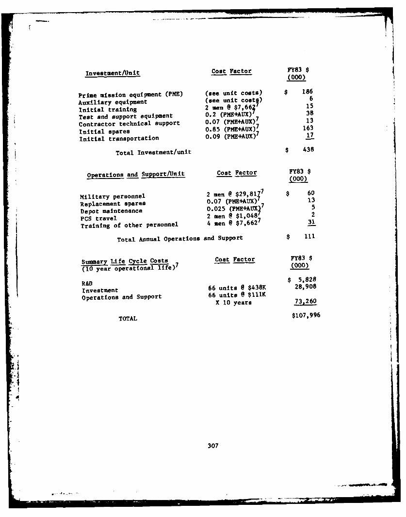
Investment/Unit Cost Factor FY83$(000)
Prime mission equipment (PME) (see unit costs) $ 186
Auxiliary equipment (see unit costs) 6
Initial training 2 men @ $7,66f7 15
Test and support equipment 0.2 (PME+AUX) 38
Contractor technical support 0.07 (PME+AUX)7 13
Initial spares 0.85 (PME+AUX)7 163
Initial transportation 0.09 (PME+AUX)7 17
Total Investment/unit $ 438
Operations and Support/Unit Cost Factor FY83 $(000)
Military personnel 2 men @ $29,8177 $ 60
Replacement spares 0.07 (PME+AUX)7 7 13
Depot maintenance 0.025 (PME+AUX 7 5
PCS travel 2 men @ $1,048 2
Training of other personnel 4 men @ $7,6627 31
Total Annual Operations and Support $ 111
Summary Life Cycle Costs Cost Factor FY83 $
(10 year operational life) 7 (000)
R&D $ 5,828
Investment 66 units @ $438K 28,908
Operations and Support 66 units @ $111KX 10 years 73,260
TOTAL $107,996
30
307

4 TANK AMKIUNITION HANDLER
Unit Investment Cost
Prime Mission Equipment (PME) Coat Factor FY83.
High flexibility arm, $ 33,00010with programmerLoading arm, with programmer 33,00010
Depalletizing arm, 33,00010
with programmerRound identifier 30,00017
Communication set 8004
Generator set, 45 kw 16,1054SComputer 10,0001,15,16
Assembly and checkout 0 I
Total PME $165,905
Auxiliary Equipment (AUX) Cost Factor FY83 $
Truck, 2 1/2 ton $ 42,46111
Total AUX $ 42,461Total PME&AUX $208,366
Life Cycle Costs
R&D Cost Factor FY83 $
(Programs 6.3 and 6.4 only) (000)
Concept formulation/feasibility 1 MY1 @ $124K 7 $ 124
studyDesign 2 MY 248
Test article fabrication 5 @ $166K 830
Developmental testing 1 MY 124Prototype fabrication 1 @ $166K 166
Software R&D 2 MY 248
System integration/test 5 MY 620
Program management 4 MY 496
Data 9 X PHE Unit Cost 7 1,494
:1 Total R&D $ 4,350
308

Investment/Unit Cost Factor FY83 $
Prime mission equipment (PME) (see unit costs) $ 166Auxiliary equipment (see unit costg) 42Initial training 1 man @ $7,66 ' 8Test and support equipment 0.2 (PME+AUX) 42Contractor technical support 0.07 (PME+AUX)7 15Initial spares 0.85 (PME+AUX)7 177Initial transportation 0.09 (PME-+AUX)7 19
Total Investment/unit $ 469
Operations and Support/Unit Cost Factor FY83 $(000)
Generator set O&M $ 711Truck, 2 1/2 ton 811
Replacement spares 0.07 (PME)7 12Depot maintenance 0.025 (PME)7 4Training of other personnel 1 man @ $7,6627 8
Total Annual Operations and Support $ 39
Summary Life Cycle Costs Cost Factor FY83 $(10 year operational life)7 (000)
R&D $ 4,350Investment 840 units @ $469K 393,960Operations and Support 840 units @ $39K
X 10 years 327,600
TOTAL $725,910
309

5 SAFE RETURN CONTROLLER
Unit Investment Cost
Prime Mission Equipment (PHE) Cost Factor FY83
Automatic flight control system $ 28,0004Navigation set, inertial 104,0006
Aircraft/pilot condition analyzer 16,9154
Voice output device 99513
Voice input device 2,36012
Computer/memory 20,0001,15,16
Assembly and checkout 10,0001
Total PHE $182,270
Auxiliary Equipment (AUX) Cost Factor FY83 $
Ground control station at home base $ 712*
Total AUX $ 712Total PME&AUX $182,982
Life Cycle Costs
R&D Cost Factor FY83 $(Programs 6.3 and 6.4 only) (000)
Concept formulation/feasibility 1 MY1 @ $124K 7 $ 124study
Design 2 MY 248Test article fabrication 8 @ $172K 1,376Developmental testing 4 MY 496Prototype fabrication 1 @ $172K 172Software R&D 6 MY 744System integration/test 5 MY 620Program management 4 MY 496Data 9 X PHE Unit Cost7 1638
Total R&D $ 5,914
*This system is estimated to cost $35,6034 per installation.
Assuming one system serves 50 aircraft only 2% of this cost is chargedto each Safe Return Controller.
310
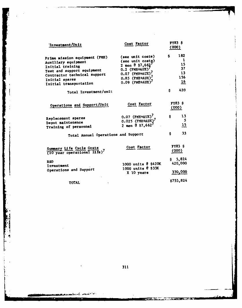
'Investment/Unit Cost Factor FY83 $
'Invetmen/Uni - -(000)
Prime mission equipment (PHE) (see unit costs) $ 182
* Auxiliary equipment (see unit costs) I
* Initial training 2 men @ $7,66 7 15
Test and support equipment 0.2 (PME+AUX)" 37
Contractor technical support 0.07 (PME+AUX)7 13
Initial spares 0.85 (PME+AUX) 7 156
Initial transportation 0.09 (PME+AUX) 7 16
Total Investment/unit $ 420
Operations and Support/Unit Cost Factor FY83 $(000)
Replacement spares 0.07 (PME+AUX)7 $ 13
Depot maintenance 0.025 (PME+AUX37 5
Training of personnel 2 men @ $7,662 15
Total Annual Operations and Support $ 33
Summary Life Cycle Costs Cost Factor FY83 $
(10 year operational ife)7 (000)
R&D $ 5,824
Investment 1000 units @ $420K 420,000
Operations and Support 1000 units @ $33KX 10 years 330,000
TOTAL $755,824
31-!
I
'. 311
-*--

6 BRIGADE MISSION PLANNING AID
Unit Investment Cost
Prime Mission Equipment (PME) Cost Factor FY83 $
Computer $ 20,0001,15,16* Power supply 4001
Voice output device 99513Voice input device 2,36012Hard copy printer 20,0001,15,16Communication links to data bases 5 @ $8001 4,000Assembly and checkout 20001
Total PME $ 49,755
Auxiliary Equipment (AUX) Cost Factor FY83 $
Truck, 1/4 ton 16,83311
Total AUX $ 16,833Total PME&AUX $ 66,588
Life Cycle Costs
R&D Cost Factor FY83 $(Programs 6.3 and 6.4 only) (000)
Concept formulation/feasibility 0.5 MY1 @ $124K 7 $ 62study
Design 1 MY 124Test article fabrication 6 @ $50K 300Developmental testing 1 MY 124Prototype fabrication 1 @ $50K 50Software R&D 5 MY 620System integration/test 3 MY 372Program management 2 MY 248Data 9 X PME Unit Cost 7 450
Total R&D $ 2,350
312

I
Investment/Unit Cost Factor FY83 $(000)
Prime mission equipment (PNE) (see unit costs) $ 50Auxiliary equipment (see unit cost5) 17Initial training 3 men @ $7,66 ' 23Test and support equipment 0.2 (PME+AUX) 13Contractor technical support 0.07 (PME+AUX)7 5Initial spares 0.85 (PME+AUX)7 57Initial transportation 0.09 (PME+AUX)7 6
Total Investment/unit $ 171
Operations and Support/Unit Cost Factor FY83 $(000)
Military personnel 2 men @ $29,8177 $ 60Truck, 1/4 ton 1011
Replacement spares 0.07 (PHE)7 4Depot maintenance 0.025 (PME)7 1PCS travel 2 men @ $1,0487 2Training of other personnel 1 man @ $7,6627 8
Total Annual Operations and Support $ 85
Summary Life Cycle Costs Cost Factor FY83 $(10 year operationalife)7 (000)
R&D $ 2,350Investment 72 units @ $171K 12,312Operations and Support 72 units @ $83K
X 10 years 61,200
TOTAL $ 75,862
313
b ..

7 EMERGENCY REPAIR AND MAINTENANCE ADVISOR (ERMA)
Unit Investment Cost
Prime Mission Equipment (PME) Cost Factor FY83 $
Computer/control panel/display $ 20,0001 ,15,16
Voice output device 99513
Voice input device 2,36012
Battery power supply 6376
Assembly and checkout 1,0001
Total PME $ 24,992
Auxiliary Equipment (AUX) Cost Factor FY83 $
Program Change Unit (PCU) 0.05* x 1,0001 $ 50Battery analyzer/charger 0.05 x 9754 49
Total AUX $ 99
Total PME&AUX $ 25,091
*For 24 Army Divisions, 96 PCUs support 2,100 ERAs or 0.05 PCU per ERA.
314

Life Cycle Costs
R&D Cost Factor FY83 $(Pograms 6.3 and 6.4 only) (000)
Concept formulation/feasibility 0.5 MY1 @ $124K 7 $ 62study
Design 1 MY 124Test article fabrication 6 @ $25K 150Developmental testing 1 MY 124Prototype fabrication 1 @ $25KC 25Software R&D 5 MY 620System integration/test 3 MY 372Program management 2 MY 248
Data 9 X PME Unit Cost7 225
Total R&D $ 1,950
Investment/Unit Cost Factor FY83 $(000)
Prime mission equipment (PME) (see unit costs) $ 25
Auxiliary equipment (see unit cost€) 0Initial training 1 man @ $7,662' 8Test and support equipment 0.2 (PME+AUX)7 5Contractor technical support 0.07 (PME+AUX)7 2Initial spares 0.85 (PME+AUX)7 21Initial transportation 0.09 (PME+AUX)7 2
Total Investment/unit $ 63
315

Operations and Support/Unit Cost Factor FY83 $(000)
Replacement spares 0.07 (PIE+AUX)7 $ 2Depot maintenance 0.025 (PME+AUX 7 ITraining of personnel I man @ $1,000?
Total Annual Operations and Support $ 4
Summary Life Cycle Costs Cost Factor FY83 $(10 year operational life) 7 (000)
R&D $ 1,950,Investment 67,400 units @ $63K 4,246,200Operations and Support 67,400 units @ $4K
X 10 years 2,696,000
TOTAL $6,943,950
316

8 TACTICAL THREAT PROJECTION SYSTEM
Unit Investment Cost
Prime Mission Equipment (PME) Cost Factor FY83 $
Computer/memory $ 20,0001,15,16
Keyboard/CRT color display 25,0001,15,16
Power supply 1)0001
Hard copy printer 30,0001,15,16
Assembly and checkout 2 0001
Total PHE $ 78,000
Auxiliary Equipment (AUX) Cost Factor FY83 $
None
Total AUX $ 0Total PME&AUX $ 78,000
Life Cycle Costs
R&D Cost Factor FY83 $
(Programs 6.3 and 6.4 only) (000)
Concept formulation/feasibility 0.5 MY 1 @ $124K 7 $ 62
studyDesign 1 MY 124
Test article fabrication 6 @ $78K 468Developmental testing 1 MY 124Prototype fabrication 1 @ $78K 78Software R&D 6 MY 744
System integration/test 3 MY 372Program management 2 MY 248Data 9 X PME Unit Cost7 702
Total R&D $ 2,922
* 31
317

Investment/Unit Cost Factor FY83 $(000)
Prime mission equipment (PME) (see unit costs) $ 78Auxiliary equipment (see unit costs) 0Initial training 2 men @ $7,6627 15Test and support equipment 0.2 (PME+AUX)7 16Contractor technical support 0.07 (PME+AUX)7 5Initial spares 0.85 (PME+AUX)7 66Initial transportation 0.09 (PME+AUX)7 7
Total Investment/unit $ 187
Operations and Support/Unit Cost Factor FY83 $(000)
Military personnel 1 man @ $29,8177 $ 30Replacement spares 0.07 (PME+AUX)7 5Depot maintenance 0.025 (PME+AUX 7 2PCS travel I man @ $1,048 ITraining of other personnel I man @ $7,6627 8
Total Annual Operations and Support $ 46
Summary Life Cycle Costs Cost Factor FY83 $
(10 year operational life)' (000)
R&D $ 2,922Investment 24 units @ $187K 4,488Operations and Support 24 units @ $46K
X 10 years
TOTAL $ 18,450
318
* ---

9 INTERROGATION SUPPORT SYSTEM
Unit Investment Cost
Prime Mission Equipment (PME) Cost Factor FY83 $
Computer/control panel/display $ 20,0001,15,16
Power supply 1,0001Hard copy printer, micro 5001,15,16
Voice output device 99513
Voice input device 2,36012
Assembly and checkout 2 0001
Total PME $ 26,855
Auxiliary Equipment (AUX) Cost Factor FY83 $
None
Total AUX $ 0Total PME&AUX $ 26,855
Life Cycle Costs
R&D Cost Factor FY83 $(Programs 6.3 and 6.4 only) (000)
Concept formulation/feasibility 0.5 MY1 @ $124K 7 $ 62
studyDesign 1 MY 124Test article fabrication 6 @ $27K 162Developmental testing I MY 124Prototype fabrication 1 @ $27K 27Software R&D 6 MY 744System integration/test 3 MY 372Program management 2 MY 248Data 9 X PME Unit Cost7 243
Total R&D $ 2,106
319

Investment/Unit Cost Factor FY83 $(000)
Prime mission equipment (PME) (see unit costs) $ 27Auxiliary equipment (see unit cost) 0Initial training 8 men @ $7,66 61Test and support equipment 0.2 (PME+AUX) 5Contractor technical support 0.07 (PME+AUX)7 2Initial spares 0.85 (PME+AUX)7 23Initial transportation 0.09 (PME+AUX)7 2
Total Investment/unit $ 120
Operations and Support/Unit Cost Factor FY83 $(000)
Military personnel 1/2 time x 8 men $ 119@ $29,8177
Replacement spares 0.07 (PME+AUX)7 2Depot maintenance 0.025 (PME+AUX)7 1PCS travel 1/2 time 1 8 men 4
@ $1,048I
Training of personnel 8 men @ $7,6627 61
Total Annual Operations and Support $ 187
Summary Life Cycle Costs Cost Factor FY83 $(10 year operational life)7 (000)
R&D $ 2,106
Investment 22 units @ $120K 2,640Operations and Support 22 units @ $187K
X 10 years 41,140
TOTAL $ 45,886
320

t
10 DIVISION COMMANDER'S QUICK DATA-ACCESS SYSTEM
Unit Investment Cost
Prime Mission Equipment (PME) Cost Factor FY83 $
Computer/control panel $ 20,0001,15,16
Voice input device 2,36012
Power supply 1,0001
Hard copy printer 30,0001,15,16
Color display 25,0001,15,16
Assembly and checkout 50001
Total PME $ 78,360
Auxiliary Equipment (AUX) Cost Factor FY83 $
Truck, 1/4 ton $ 16,83311
Total AUX $ 16,833Total PME&AUX $ 95,193
Life Cycle Costs
R&D Cost Factor FY83 $(Programs 6.3 and 6.4 only) (000)
Concept formulation/feasibility 0.5 MY1 @ $124K 7 $ 62study
Design 1 MY 124Test article fabrication 6 @ $78K 468Developmental testing I MY 124Prototype fabrication 1 @ $78K 78
Software R&D 4 MY 496System integration/test 3 MY 372Program management 2 MY 248Data 9 X PME Unit Cost7 702
Total R&D $ 2,674
321

Investment/Unit Cost Factor FY83 $(000)
Prime mission equipment (PME) (see unit costs) $ 78Auxiliary equipment (see unit costs) 17Initial training 2 men @ $7,66f 7 15Test and support equipment 0.2 (PME+AUX) 19Contractor technical support 0.07 (PME+AUX)7 7
Initial spares 0.85 (PME+AUX)7 81Initial transportation 0.09 (PME+AUX)7 9
Total Investment/unit $ 226
Operations and Support/Unit Cost Factor FY83 $(000)
Military personnel 1 man @ $29,8177 $ 30Truck, 1/4 ton l0l l
Replacement spares 0.07 (PHE)7 5Depot maintenance 0.025 (PME)7 2PCS travel I man @ $1,0487 ITraining of other personnel I man @ $7,6627 8
Total Annual Operations and Support $ 56
Summary Life Cycle Costs Cost Factor FY83 $(10 year operational life)7 (000)
R&D $ 2,674Investment 24 units @ $226K 5,424Operations and Support 24 units @ $56K
X 10 years 13,440
TOTAL $ 21,538
322

REFERENCES TO APPENDIX B
1. SRI engineering estimate.
2. "U.S. Military Aircraft," Aviation Week and Space Technology,
Vol. 114, No. 10, pp. 116-117 (9 March 1981).
3. Cost and Planning Factors Regulation, Air Force Regulation 173-13
(1 February 1981).
4. Army Adopted/Other Selected Items and List of Reportable Items,Army Supply Bulletin, SB 700-20, (1 September 1981).
5. Systems Analysis of Remote Piloting/Robotics Technology Applicableto Assault Rafts, Final Report, Arthur D. Little, Inc. Cambridge,Massachusetts (January 1982).
6. "Advanced Remotely Piloted Vehicle," Appendix D: Life Cycle Cost,
System/Subsystem Summary Report, Northrop Corporation, Venture
Division, Newbury Park, California (22 April 1976).
7. Defense Communications Agency, Cost and Planning Factor Manual>,DCA Circular 600-60-1 (May 1976, Revised to December 1981).
8. Handbook, Army Reference Data, U.S. Army War College, Carlisle
Barracks, Pennsylvania (1978).
9. Logistics Reference Data (formerly NWIP 11-21), NAVMAT P-4000-2,
Headquarters Naval Material Command (30 September 1973).
9. Tanner, W. R., ed., Industrial Robots, Volume 1: Fundamentals,Second Edition, pp. 21-26, Robotics International of SME,
Dearborne, Michigan (1980).
10. Cost Estimating Handbook (Methods and Factors), U.S. ArmyCommunications Research and Development Command, Fort Monmouth, New
Jersey (March 1980).11. "Price List for Auricle I and Auricle PCB," Threshold Technology
Inc. (private communication).
12. Moyna, M., VOTRAX Division of Federal Screw Works (privatecommunication).
13. Baker, R., Director, HVS Image Analyzing (private communication).
323
Z-7.2r

14. "DEC VAX 11-780 Managment Summary," from DATAPRO Reports onMinicomputers, DATAPRO Research Corporation (April 1980).
15. "3600 Symbol Processing Systems," from Symbolics Inc. price list(April 1981).
16. Cronin, M. J., "Price List for Programmable Visual InspectionSystem," AUTOVISION II, Automatix, Inc. (February 1981).
17. The Division Field Manual, FM 61-100, Headquarters, Department ofthe Army (1969).
18. The Battalion Field Manual, Headquarters, Department of the Army(1968).
19. Bigelman, Major P., "Army 86 Blueprint for Tomorrow," Army, pp. 21-42 (June 1981).
20. Organization of Brigade and Battalion Manual, U.S. Army InfantrySchool, Fort Benning, Georgia (1978).
21. Command and Staff Manual, U.S. Army Infantry School, Fort Benning,Georgia (1978).
22. Infantry Reference Data, Volumes I and II, ST7-157, U.S. ArmyInfantry School, Fort Benning, Georgia (FY 1975).
I