cyberphysical security testbed for embedded systems and hybrid
59
CYBERPHYSICAL SECURITY TESTBED FOR EMBEDDED SYSTEMS AND HYBRID CYBERSECURITY CYPHER A THESIS SUBMITTED TO THE GRADUATE DIVISION OF THE UNIVERSITY OF HAWAI’I AT MANOA IN PARTIAL FULFILLMENT OF THE REQUIREMENTS FOR THE DEGREE OF MASTER OF SCIENCE IN MECHANICAL ENGINEERING DECEMBER 2017 By Freddie E. Wheeler Jr. Thesis Committee: Reza Ghorbani, Chair Peter Berkelman Scott Miller Keywords: cybersecurity, cyberphysical, testbed, hybrid cypher, RSA encryption, chaotic neural network, renewable energy, home energy management
-
Upload
khangminh22 -
Category
Documents
-
view
4 -
download
0
Transcript of cyberphysical security testbed for embedded systems and hybrid

CYBERPHYSICAL SECURITY TESTBED FOR EMBEDDED SYSTEMS AND HYBRID
CYBERSECURITY CYPHER
A THESIS SUBMITTED TO THE GRADUATE DIVISION OF THE
UNIVERSITY OF HAWAI’I AT MANOA IN PARTIAL FULFILLMENT
OF THE REQUIREMENTS FOR THE DEGREE OF
MASTER OF SCIENCE
IN
MECHANICAL ENGINEERING
DECEMBER 2017
By
Freddie E. Wheeler Jr.
Thesis Committee:
Reza Ghorbani, Chair
Peter Berkelman
Scott Miller
Keywords: cybersecurity, cyberphysical, testbed, hybrid cypher, RSA encryption, chaotic neural
network, renewable energy, home energy management

ii
ACKNOWLEDGEMENTS
I would like to thank Dr. Ghorbani for his guidance, support, and patience as I went through this
project. I would also like to extend a large thanks for Dr. Lyes Saad Saoud for his help in this
project. In addition, I would like to thank all of the members of the REDlab, especially Mahdi
Motalleb and Matsu Thornton. Your help was tremendous to the success of this project. A large
thank you to the Applied Research Laboratory at UH Manoa for their funding and support of this
project.

iii
ABSTRACT
Research was conducted on a hybrid cybersecurity cypher for 8-bit microcontrollers. The cypher
combines RSA Algorithm and chaotic neural network to encrypt and decrypt data. MATLAB
simulations are included that show successful encryption and decryption of various data formats,
including audio and image data. An additional experiment was run on Arduino to show that data
can be encrypted and decrypted with speed on an 8-bit system. The speed of encrypting a data
stream is acceptable for sensor level data on a SCADA network. However, for larger data
streams, like video, more optimization needs to be made in order to encrypt and decrypt that data
quickly.

iv
TABLE OF CONTENTS
Acknowledgement………………………………………………………………………………...ii
Abstract…………………………………………………………………………………………...iii
List of Tables……………………………………………………………………………………...v
List of Charts, Graphs, Figures, Illustrations, Plates, Maps……………………………………...vi
List of Abbreviations and/or Symbols…………………………………………………………...vii
Preface…………………………………………………………………………………………..viii
Introduction………………………………………………………………………………………..1
Software Solution………………………………………………………………………………….4
Hardware and Testbed…………………………………………………………………………...10
Results……………………………………………………………………………………………11
Conclusion……………………………………………………………………………………….16
Appendix A – Code……………………………………………………………………………...17
Appendix B – Additional Figures………………………………………………………………..13
Works Cited……………………………………………………………………………………...38

v
LIST OF TABLES
Table 1: Time to Encrypt and Decrypt Home Load Data………………………………………..12
Table 2: Time to Encrypt and Decrypt Audio Signal……………………………………………13
Table 3: Time to Encrypt and Decrypt Image Based of Wavelet Level…………………………13
Table 4: Time to Encrypt and Decrypt Images of Varying Size: Wavelet Level 1……………...14
Table 5: Time to Encrypt and Decrypt Pictures of varying size…………………………………15
Table 6: Time to Encrypt and Decrypt Varying amounts of Data Points………………………..16

vi
LIST OF CHARTS, GRAPHS, FIGURES, ILLUSTRATIONS, PLATES, MAPS
Figure 1: Basic Concept of Neural Network………………………………………………………7
Figure 2: Process for RSA-CNN Encryption/Decryption…………………………………………9
Figure 3: Completed Physical Testbed…………………………………………………………..11
Figure 4: Home Load Data through RSA-CNN Process………………………………………...12
Figure 5: Audio Signal through RSA-CNN Process……………………………………………..13
Figure 6: Results of Wavelet Decomposition and Encryption…………………………………...14
Figure 7: Screenshots of Image during Different Parts of RSA-CNN Process………………….15
Figure 8: Graph of 100 Data Points Encrypted and Decrypted by Arduino……………………..15

vii
LIST OF ABBREVIATIONS AND/OR SYMBOLS
CCTV – closed circuit television
CNN – chaotic neural network
DiD – Defense-in-Depth
EV – electric vehicle
FPGA – field programable gate array
GENCO – generation company
HITL – hardware-in-the-loop
IoT – Internet of Things
ISO – independent service operator
PUC – public utilities commission
PV – photovoltaic (i.e. solar panels)
RSA Encryption – Rivest, Shamir, Adleman Encryption
SCADA – supervisory control and data acquisition

viii
PREFACE
The Internet of Things (IoT) sector is growing at a rapid pace. The use of these products
are starting to become more and more common in the business and residential sector. Products
like the Amazon Echo and Google Home are examples of IoT products that are seeing more and
more adoption in homes. The energy sector is moving towards IoT technology in order to
monitor and control the power grid as well as gain more visibility about renewable generation
resources. In order to ensure a constant supply of energy, this information and control network
has to be encrypted to protect the grid.
There is a need to research a reliable encryption method that is low in both computational
and device cost. As more and more devices are connected to the internet, securing these devices
in a way that is economically efficient becomes a larger priority.

1
INTRODUCTION
The energy sector is moving towards technology from the Internet of Things (IoT) sector.
This means that the power grid would be connected to a host of sensors and devices that have
internet connectivity and therefore communications capability that was previously unheard of in
the power grid. These smart grids will greatly enhance the ability of the utilities to operate them
and maintain their stability. In addition, as renewable energy resources are becoming more and
more common, using IoT technology is a great way to get visibility on the availability of
renewable energy and can further help the utilities to plan their own generation [1].
In addition, there are numerous efforts around the world to build “Smart Cities”, or cities
that use increasing amounts of automation and device communication to help streamline various
services such as waste management, power management, and even automatic ride-sharing
services. The Amsterdam Smart City Initiative and the Smart Dubai Initiative are examples of
smart city initiatives that aim to bring a higher level of technology to aid in increasing the
comfort levels of the people in those cities [2,3]. Examples of initiatives from those cities
involve using sensors to monitor and control the battery levels in electric vehicles (EV) when
they are connected to the grid, as well as using sensors to monitor the availability of parking
spaces in an outdoor parking lot [3]. Another example of the scope of communication involved
in these smart cities is Dubai’s idea of “Smart ICT Infrastructure”. This is where devices and
services citywide are connected and coordinated over a network in order to improve efficiency in
multiple areas. They define those areas as citywide connectivity, sensing and actuation to drive
efficiency, data orchestration and analysis, smart service delivery apps, and centralized
monitoring and management [2].
IoT technologies will be the foundation of these smart cities. Without the
interconnectivity that these devices provide, the level of real-time coordination required in order
to effectively improve performance would be nearly impossible. IoT devices are seeing more and
more use in people’s homes and in industry. It is estimated that 26 billion IoT devices will be in
use by 2020, compared to just 7.3 billion units of computers, laptops, and smartphones. That
number will keep getting larger as the adoption of these devices will accelerate further adoption
of these technologies as more consumers will find the improvement it gives to their daily life to
be worth the cost of investment [4].

2
However, this increase in communication devices brings with it several challenges. One
is the cybersecurity aspect. Most cybersecurity cyphers utilize encryption keys that are large in
bit size, either 512-bits or larger. This is done because a large bit key is almost impossible to
crack using a brute force method in any reasonable amount of time. Most computers can run
encryption using keys of those sizes at a reasonable pace for most applications, like sending
emails or pictures. However, heavy encryption with large keys, 1024 or 2048-bit keys, are too
large for consistent real-time applications. Real-time in this instance is defined as a timestep that
is 5 seconds or shorter in length [5]. The main type of system that would utilize a timestep of this
size is the smart grid. The smart grid would rely on communication from devices and sensors
that send information about their state roughly every second to make informed, autonomous
decisions on how to maintain grid balance [1].
In addition, most IoT devices are made with smaller microprocessors that cannot handle
the computations that a larger key cypher would necessitate. Most IoT devices contain
microprocessors that are 32-bits or lower, and do not contain a lot of RAM. These devices cost
on average $10, compared to computer-grade processors which cost on average $300. For
example, an 8-bit microprocessor has to deal with overflow when it handles a number larger than
255. It does this by breaking up the larger number into smaller bit sizes that the processor can
handle. It then sends each segment to a different bus on the processor, cascading the signals, and
using timing inputs to the ALU unit for reconstruction using memory allocated in that unit [6].
For an 8-bit microprocessor with only 6 busses, it would take 21.3 computation cycles to process
a single 1024-bit number. Given that the RAM for a 8-bit microprocessor is usually 512 bytes,
those computation cycles could take a long time to complete as it would need to send the data
over once the memory is full [7]. IoT networks will need to communicate in real time in order to
provide the information necessary to coordinate and improve efficiency across multiple systems.
Cybersecurity is one of the more important issues facing the smart grid. For various
reasons, the information that would be transmitted across a smart grid is very sensitive. There is
the customer’s privacy to worry about, as data from their energy consumption could be stolen
and used to determine information about their daily routine. The grid operators, whether they be
utilities or ISOs, will want to ensure that the data they are getting from sensors and smart meters
is correct and untampered with. If a hostile party were to tamper with the information going to
the system operators, those operators could make a mistake in their corrective actions and cause
the power grid to destabilize. In a similar manner, a hostile entity could intercept or otherwise

3
change the signals for demand response and cause the wrong type of corrective action to be taken
even though the system operator had initially dispatched the correct amount of demand response
[8].
The other main issue with IoT devices is how to upgrade a network of distributed sensors
and devices that can number in the hundreds of thousands. These devices can come from
different manufacturers and they must all be able to communicate with each other. Therefore, a
solution must be made that works for any type of device and allows these devices to talk to each
other and to a centralized command center. An important aspect of this is to ensure that the
encryption devices are economically feasible and made with low-cost hardware. Cities like
Dubai have already installed tens of thousands of CCTV cameras across the city and it would be
extremely prohibitive for a municipality like them to replace all of the cameras that they just
installed just to make them more secure from cyberattack. This is not because they do not care
about cybersecurity, but rather because of the cost in both supplies and manpower that would be
needed to once again replace devices that were installed not too long ago. This line of thinking
can be applied to any type of IoT device network that will be part of the “Smart City”
development. Some of these programs have already started installing devices, and they are not
looking into replacing those devices that they have just installed until a better all-around device
is developed.
Therefore, the economic viability of this solution is also of major importance to the
power management sector. A distributed network of sensors and substations is very difficult to
upgrade with any form of technology. Utilities most often pass the cost of any upgrades along to
the public who use their services. This is because their profits are closely regulated and they do
not have the extra profit that allows for infrastructure improvements without impacting their
customers [9]. This is also true for any city municipality that wishes to create a distributed IoT
network. Most public projects are funded through taxpayer’s dollars. If there is a project that
could potentially cost a lot of money, the public’s taxes would also increase. If there were to be a
vote on whether or not to increase taxes in order to proceed with the project, that vote could fail
and the project could stall [10]. For example, the PUC in Hawaii is in charge of approving any
large-scale projects that involve improving and upgrading the infrastructure. They receive
dockets from the utilities that detail their plans to improve and how much capital it would cost to
implement the proposed project. In FY 2016, the PUC in Hawaii issued 783 decisions and orders

4
to utilities regarding the status of their proposals [9]. Some were approved and others were
denied and sent back to the utilities for revision.
Therefore, one can establish that there is a need to secure the information that would be
transmitted on the smart grid, and any IoT network in general, in a secure and economically
efficient manner. This encryption would have to still enable real-time communication across the
grid, and be economically viable enough to warrant installation in devices and sensors grid-wide.
In addition, the resulting cybersecurity platform must facilitate communication between devices
and communication networks that come from different manufacturers which would never
normally be able to communicate with each other. This level of communication is necessary for
an autonomous smart network to make decisions using all of the information at its disposal.
Along with the inclusion of cybersecurity in the IoT sector, there is a need to test new
devices and changes to these sensor networks without impacting them. This type of hardware-in-
the-loop (HITL) simulation is very helpful in getting the results of real devices and how they
affect the systems that they are connected to. For example, since the power grid is
interconnected, any serious malfunction could impact its reliability in a certain area. By creating
a testbed that can accurately simulate the grid conditions to test devices and protocols, the ability
to quickly iterate and design solutions will be vastly improved. These types of simulations have
the benefit of being isolated systems that offer a high degree of controllability. This means that
severe conditions can be tested without putting the actual system at risk. This is very beneficial
in the realm of research in that you can quickly and repeatedly simulate situations that are not
commonly occurring.
In the areas of the power grid and renewable energy, certain transient events are difficult
to accurately predict. Events like passing cloud cover are difficult to plan an experiment around
if the desire is to use the real weather. However, using simulations based on real world data,
researchers can quickly iterate through various solutions and test devices for their efficacy on a
connected hardware system. The level of control over the simulation will allow for testing under
conditions that will give meaningful insight into how the software and hardware of these
cybersecurity platforms affect the systems they are connected to.

5
SOFTWARE SOLUTION
The issue of generating a cybersecurity network for a SCADA network is the issue of
encrypting data for a system that needs to operate in real time. Cybersecurity is traditionally
computationally expensive to implement. It is fine for computers to have this expensive type of
encryption, it is very costly to ensure that an entire SCADA network’s access points are secure if
they require the hardware of a desktop computer. The utilities and power systems companies are
looking into cost-effective ways of securing the transmission of data across the power grid
network.
The solution to the problem requires that the cybersecurity cypher be less
computationally expensive so that it can run on cheaper microchips that can encrypt and decrypt
data in real-time. To that end, a hybrid cypher was created that combines the principles of RSA
cryptography with that of a chaotic neural network (CNN). This hybrid cypher, referred
throughout this paper as RSA-CNN, aims to take the less computationally expensive aspects
from each cypher and combine them in a package in such a way that keeps the level of security
high while lowering the computational cost. This saving in computational cost translates to
savings in hardware costs, which allows utilities to easily deploy this technology onto their grid
without severely impacting their customers’ electricity bill, in alignment with the mission
statement from public utilities commissions, who are tasked with regulating the profits of utilities
across the country [11].
RSA cryptography was invented by three gentlemen from MIT, Ron Rivest, Adi Shamir,
and Leonard Adleman. It is based off of public and private “keys” that are used to encrypt and
decrypt data [12]. RSA cryptography is currently used for things over the internet such as online
shopping or digital signatures for websites to show that they are the website that they say they
are [13,14].
The first step in RSA cryptography is to choose two prime numbers: p and q.
𝑝 = 𝑝𝑟𝑖𝑚𝑒 𝑛𝑢𝑚𝑏𝑒𝑟 #1, 𝑞 = 𝑝𝑟𝑖𝑚𝑒 𝑛𝑢𝑚𝑏𝑒𝑟 #2
Then these numbers are multiplied to compute the value of n.
(1) 𝑛 = 𝑝 × 𝑞
The next step involves finding the value of Φ, which is equal to p – 1 and q – 1.
(2) 𝜙 = (𝑝 − 1) × (𝑞 − 1) = 16 × 40 = 640

6
Taking Φ, the value of e is chosen such that it is less than Φ, and the greatest common
factor of both Φ and e is equal to 1.
(3) 𝑔𝑐𝑓(𝜙, 𝑒) = 1, 𝑒 < 𝜙
Then the value of d is calculated, using the modular multiplicative inverse of e. The
equation is listed below:
(4) 𝑑 = 𝑒 × 𝑚𝑜𝑑(𝑛)
The combination of the values of n and e are considered the “public key” and is what
other entities use to encrypt a data packet they wish to send to you. The encryption equation is
listed below:
(5) 𝑚𝑒𝑠𝑠𝑎𝑔𝑒𝑒𝑛𝑐 = (𝑚𝑒𝑠𝑠𝑎𝑔𝑒)𝑒 × 𝑚𝑜𝑑(𝑛)
The combination of values of n and d are considered the “private key”. This is what an
entity uses to decrypt an encrypted message that was sent to them using their public key.
(6) 𝑚𝑒𝑠𝑠𝑎𝑔𝑒 = (𝑚𝑒𝑠𝑠𝑎𝑔𝑒𝑒𝑛𝑐)𝑑 × 𝑚𝑜𝑑(𝑛)
An example of the whole sequence of RSA cryptography from encryption to decryption
is found below:
𝑝 = 17, 𝑞 = 41
𝑛 = 17 × 41 = 697
𝜙 = (17 − 1) × (41 − 1) = 640
𝑔𝑐𝑓(640, 𝑒) = 1 ∴ 𝑒 = 77
𝑑 = 77 × 𝑚𝑜𝑑−1(697) = 133
𝑃𝑢𝑏𝑙𝑖𝑐 𝐾𝑒𝑦: (𝑛, 𝑒) = (697,77)
𝑃𝑟𝑖𝑣𝑎𝑡𝑒 𝐾𝑒𝑦: (𝑛, 𝑑) = (697,133)
𝑚𝑒𝑠𝑠𝑎𝑔𝑒 = 32
𝑚𝑒𝑠𝑠𝑎𝑔𝑒𝑒𝑛𝑐 = (𝑚𝑒𝑠𝑠𝑎𝑔𝑒)𝑒 × 𝑚𝑜𝑑(𝑛) = (32)77 × 𝑚𝑜𝑑(697) = 155
𝑚𝑒𝑠𝑠𝑎𝑔𝑒 = (𝑚𝑒𝑠𝑠𝑎𝑔𝑒𝑒𝑛𝑐)𝑑 × 𝑚𝑜𝑑(𝑛) = (155)133 × 𝑚𝑜𝑑(697) = 32
The value that RSA encryption provides is that it is a fairly simple method of encryption.
The cypher is based off of two prime numbers and, once the public and private keys have been
calculated. The encryption and decryption are each done through one equation, equations 5 and
6, respectively.
However, what makes this equation so simple to use is also the main flaw in this version
of the cypher. Since it relies on a pair of prime numbers, there is a finite number of key pairs that

7
exist for a given cypher. For smaller 8-bit systems, like the kind you find on low-cost
microcontrollers, the size of the prime numbers used in the key generation are very small. When
a hostile entity intercepts a message, they can find out the value of n, and therefore factor it to
find the values of p and q. For larger RSA keys, such as 512-bit or larger, the length of time for a
brute force attack is much larger. To date, the largest key that was decrypted was 768-bits in size.
According to the authors, it would take approximately 2000 years for a single 2.2 GHz AMD
Opteron to break a key of this size [15].
However, most IoT devices use microprocessors that are much less powerful than the
ones on a computer. This means that, if the desired function of this IoT encryption is to use it for
communication of data within a 1 second timestep without using expensive hardware, the RSA
key would have to be much smaller. Something along the lines of 8 to 16 bits in size. For
comparison, factoring a 330-bit RSA key took only 5.3 days on a single 16K MasPar [16].
Simply put, using a key size of 64-bits or lower would be inadequate due to the lack of security;
there are only so many prime numbers within that range of numbers. Therefore it must be paired
with an encryption process that is both secure and computationally inexpensive.
The chaotic neural network (CNN) is the other half of this hybrid encryption that solves
the issue of most cyphers being computationally expensive. Regular neural networks have been
shown to be computationally faster than traditional RSA encryption [17]. This is due to the
simpler nature of the math involved in each step of the operation. However, the structure of a
neural network is what makes it acceptable as a form of encryption. In order to get the correct
value that is encrypted by a neural network, the decryption neural network has to have the same
weights and structure. If there is a difference between the networks, then the decrypted results
will not match the original encrypted values. Figure 1 shows the basic format of a neural
network.

8
Figure 1: Basic Concept of Neural Network
The neural network used in our hybrid cypher is known as a chaotic neural network. This
is done because the initial values put into the network’s input layer are randomized. This means
that the path the input takes through the layers is different each time and without the correct
initial value, the initial value cannot be decrypted. The input is randomized in the CNN through
two values, α and xs. These values themselves are randomized every time an encrypted message
is sent. The CNN used in this experiment has 3 layers that serve to scramble the binary values of
the data being encrypted.
The following paragraph details the code and math behind the chaotic neural network.
First the values of α and xs are randomly generated using the following equations:
(7) 𝛼 = 0.45 ∗ 𝑟𝑎𝑛𝑑 + 0.04
(8) 𝑎 = 𝛼, 𝑏 = 1 − 𝛼
(9) 𝑥𝑠 = (𝑏 − 𝑎) ∗ 𝑟𝑎𝑛𝑑 + 𝑎
From there, the values of μ and λ are created from α.
(10) 𝜇 =4
1 − 2 ∗ 𝜆
(11) 𝜆 = 𝛼 ∗(2 ∗ 𝛼 − 3)
(1 − 2 ∗ 𝛼)
After μ and λ are generated, then the remaining values of x are generated using the
following equation:
(12) 𝑥 = 𝜇 ∗ 𝑥(𝑖 − 1) ∗ (1 − 𝑥(𝑖 − 1)) + 𝜆

9
From x, the matrix b is generated, it contains the binary representation of the values in x.
The matrix b is then the input into the neural network to be encrypted further. First, each byte is
given a weight and a value of θ in the first input layer.
for i=1:n for j=1:n if (b(c,i)==0)&&(i==j) weight(i,j)=1; elseif (b(c,i)==1)&&(i==j) weight(i,j)=-1; elseif i~=j weight(i,j)=0; end end if (b(c,i)==0) theta(i)=-1/2; else theta(i)=1/2; end end
Then the values of weight, the original data in binary form, XX, and theta are used to
generate a matrix, dx, in the second layer of the network.
for i=1:n %dx(c,i) = hardlim(sum(weight(i,:).*XX(c,:))+theta(i)); if sum(weight(i,:).*XX(c,:))+theta(i) >= 0 dx(c,i)=1; else dx(c,i)=0; end end
The final layer of the network takes the binary values generated in the second layer and
reconstitutes them as an 8-bit integer.
for i=1:n Y(c)=Y(c)+uint8(dx(c,i))*(2^(n-i)); end
The decryption code is structured exactly the same way, but does not use equations 7
through 12 in order to generate the values of α and xs. Instead the correct α and xs are sent over in
the data to ensure that the neural network goes along the same path.
The way the code is structured, only the α and xs values are encrypted using RSA
encryption. The rest of the data that is being sent is being encrypted using the CNN. Figure 2
shows the flow of the RSA-CNN cypher.

10
Figure 2: Process for RSA-CNN Encryption/Decryption
This structure combines the two different cybersecurity cyphers and combines them into
one process that utilizes aspects from both cyphers. The RSA encryption is used to secure the α
and xs that is used in the CNN encryption. In order to have it randomized, the α and xs that was
used to generate the chaotic sequence have to be sent along with the encrypted data. If those
parameters were not secure, it would be easier for them to correctly decrypt the CNN encrypted
data.
The Department of Homeland Security has recently put out papers and recommended
practices that talk about using Defense-in Depth (DiD) in order to help secure systems from
cyberattack, particularly industrial control systems [18]. Defense-in-Depth is the concept that
putting multiple barriers in place to prevent cyberattack is the best practice. The DiD strategy is
the driving philosophy behind the RSA-CNN cypher. It has been proven time and time again that
no cybersecurity cypher or system architecture is hack proof. The Stuxtnet virus successfully
compromised the Natanz Nuclear Facility in Iran, which was an air-gapped system [19]. The goal
is to make cracking the cypher take longer than the time required to detect the intrusion and start
either manual or automated countermeasures. The RSA-CNN cypher contains several layers of
defenses.
The first layer is the RSA encryption of α and xs that is used to start the CNN encryption
process. Without the correct public and private key, α and xs will not be correct. The second layer

11
is the α and xs that is needed in the CNN process; if those two values are incorrect, then the CNN
will not decrypt to the correct values. The third layer is the CNN itself, if the neural network is
not structured and trained in exactly the same way as the encrypting CNN, then it will not
properly decrypt the values. A hostile entity would have to break through all three layers of that
encryption at a minimum in order to gain access to the data. In addition, if there is any change to
the RSA keys or the CNN, then the hostile entity essentially has to restart the attempt to crack
the cypher. There can be multiple levels of authentication as well that can help prevent an
unwanted entity from accessing these devices, such as passwords, password length, or device ID.
By further encrypting these extra authentications in separate instances of CNN encryption, the
multiple instances of random α and xs further increase the security of the cypher.

12
HARDWARE AND TESTBED
The hardware used in this experiment was an ASUS laptop computer, with an Intel core
i7 processor, and an Arduino Uno R3. Several experiments were run on the desktop computer,
using MATLAB to run code. One experiment was done on the Arduino Uno, to see the ability of
the program to run the RSA-CNN cypher.
The testbed, which was developed in parallel with this experiment, was created to
interface with these devices and simulate an actual grid environment to see how these solutions
would affect a real-world system under real-world conditions. The testbed consists of two
inverters, a battery charger, and a home energy management system, all from Victron Energy.
The rest of the equipment is from Eaton and consists of a power distribution block, several cut-
off switches, and outlets for plugging in appliances or other devices. It also has 6 Outback
batteries for storing excess generation. Figure 3 shows the completed testbed.
Figure 3: Completed Physical Testbed
The testbed is able to be connected to either a single phase or two-phase building and can
be charged from a power supply, like the one shown in Figure 3, or can be charged using solar
panels.

13
RESULTS
Several tests were done using MATLAB code in order to see the various uses for this
encryption. The first step was to encrypt power load data from a home. The first experiment
consists of two main scripts, “ENC2.m” and “DEC2.m”. The code takes 1000 points of the load
data and encrypts it using the CNN. It then encrypts the α and xs that was used in the CNN using
the RSA encryption. It then encrypts the password using the CNN and encrypts the password’s α
and xs using RSA encryption. Figure 4 shows the original data, the data after encryption, and the
decrypted data. Table 1 shows the time, in seconds, that it took to encrypt and decrypt the 1000
data points.
Figure 4: Home Load Data through RSA-CNN Process
Table 1: Time to Encrypt and Decrypt Home Load Data
Encryption Time (s) Decryption Time (s)
0.0987 0.0712
The next test was done using the RSA-CNN cypher to encrypt an audio file that was
captured on a microphone. This encryption and decryption was also done through MATLAB.
The audio was recorded with a small Samsung earbud microphone. The recording time was 2
seconds. The sample rate of the microphone is 8kH, meaning that the data being encrypted is
16000 samples. Figure 5 shows the plots of the original audio signal, the encrypted audio signal,

14
and the decrypted audio signal. Table 2 shows the time it took to encrypt and decrypt the audio
signal.
Figure 5: Audio Signal through RSA-CNN Process
Table 2: Time to Encrypt and Decrypt Audio Signal
Encryption Time (s) Decryption Time (s)
1.835 1.222
The encrypted audio is simply static noise and is useless to anyone who intercepts the
message without being able to properly decrypt the message.
The next experiment was to encrypt a picture. This was done two ways. Once was done
by wavelet decomposition, and the other was done by using the RSA-CNN cypher on the raw
data of the image itself. The wavelet decomposition has varying levels of encryption. This affects
how heavily scrambled the image becomes; the higher the wavelet level, the lower the
decomposition. The decomposition filter used in this experiment was a Symlet 4 filter. The
wavelet level also affects the speed of the encryption. The decomposed data is then passed
through the CNN encryption and the wavelet level, α, and xs are RSA encrypted. Table 3 shows
the time to encrypt and decrypt the data based off of several tested wavelet levels. Table 4 shows
the time to encrypt and decrypt the data based of the size of the image. Figure 6 shows the results
of the different levels of wavelet decomposition, as well as the original and decrypted image.
Table 3: Time to Encrypt and Decrypt Image Based of Wavelet Level
Wavelet Level Encryption Time (s) Decryption Time (s)

15
1 846.67 592.21
2 233.30 135.63
3 34.44 18.01
4 7.17 4.41
5 1.86 1.60
10 0.35 0.33
20 0.39 0.32
Table 4: Time to Encrypt and Decrypt Images of Varying Size: Wavelet Level 1
Image Size (kB) Encryption Time (s) Decryption Time (s)
13 2.37 1.82
96 846.67 592.21
369 2979.01 2114.14
Figure 6: Results of Wavelet Decomposition and Encryption
It is important to note that the data being transmitted is still in JPEG format. The wavelet
decomposition and encryption only serve to scramble the image and its colors. If a hostile entity
were to intercept the message, they would know that it is a picture, even if they could not see
what the picture is.
The other method is to simply encrypt and decrypt the JPEG data using the RSA-CNN
cypher. In this case, once encrypted, the picture cannot be opened until it is decrypted. This is
because it changes the .jpg header so that the computer does not recognize it as such. Once
decrypted, the picture can be opened. Figure 7 shows the image before encryption, after
encryption, and after decryption. Table 5 shows the time it took to encrypt and decrypt pictures
of varying size.
16
Figure 7: Screenshots of Image during Different Parts of RSA-CNN Process
Table 5: Time to Encrypt and Decrypt Pictures of varying size
Image Size (kB) Encryption Time (s) Decryption Time (s)
13 0.90 1.02
96 51.74 57.18
369 1429.27 1542.13
The last set of experiments involved using MATLAB to send data to an Arduino, which
contained the RSA-CNN encryption code. It then sent the encrypted data back to MATLAB. The
encrypted data was then sent to an Arduino that was running the RSA-CNN decryption code.
The decrypted data was sent back to MATLAB for comparison. There is a pause of 0.5 seconds
between MATLAB sending the data to the Arduino and MATLAB reading the data that was
either encrypted or decrypted. This simulates a realistic polling time for a real-time network.
Most sensors would be sending data at either the second or half-second time-step in order to
provide a clear picture of what is occurring in the system. Figure 8 shows the results of
encryption and decryption for 100 data points, and Table 6 shows the time it took to encrypt and
decrypt varying amounts of data; this includes the half-second delay in the communication code.

17
Figure 8: Graph of 100 Data Points Encrypted and Decrypted by Arduino
Table 6: Time to Encrypt and Decrypt Varying amounts of Data Points
Data Points Encryption Time (s) Decryption Time (s)
100 5.11 5.13
1000 52.49 52.49
10000 526.74 526.65

18
CONCLUSION
The RSA-CNN cypher works to encrypt and decrypt information correctly and in a
secure manner. It is able to operate on an 8-bit microprocessor similar to what you would find on
many IoT devices. In terms of its applications, it has the ability to work for multiple media
formats as well as raw data. This is useful in the world of IoT development, where these devices
handle different types of information and media. Being able to make these devices more secure
to cyberattack will help the advancement of IoT development as well as its adoption by the
public.
The experimental results of the MATLAB and Arduino tests have shown that things like
raw data can be encrypted at a reasonable pace for real-time SCADA networks that want to
utilize communication on a 1 second timestep. For things like pictures or video, the files can be
encrypted, but it takes much longer to encrypt that data. In addition, the RSA-CNN cypher has
been shown to work on an 8-bit system, like an Arduino, and can therefore be implemented in
low-cost, low-power devices that are frequently used in the IoT sector. They can also be
implemented in the future development of IoT devices without greatly increasing the cost of the
device.
The next step in this research would be to create a stand-alone device using a PIC
microcontroller that contains the RSA-CNN cypher and use it in the cyber-physical testbed. The
cybersecurity device should be placed between IoT smart devices, in this case the Victron Home
Management System, and the rest of the grid simulation in order to see how well the device can
communicate and act on decisions made by the central utility in real time. Additional research
can be done to reformat the code to run on 16-bit and 32-bit microprocessors. These devices can
then be tested for speed and perhaps a larger security factor by using larger RSA keys.
19
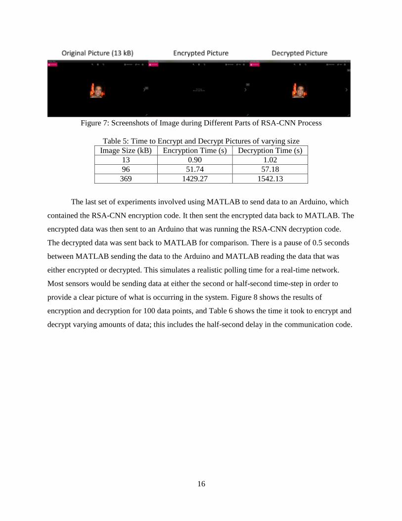
APPENDIX A - CODE
CNN_enc5.m
%#codegen
function [Y, alpha, xs, weight, XX]=CNN_enc5(X)
n=8;
l=length(X);
XX = zeros(l,n);
for i=1:l
XX(i,:)=bitget(X(i),n:-1:1);
end
alpha=str2num(num2str(0.45*rand+0.04));
alpha=0.45*rand+0.04;
alpha=floor(alpha*100000);
alpha=alpha/100000;
%alpha=0.16462;
a = alpha;
b = 1-alpha;
%x(1) = str2num(num2str((b-a).*rand+ a));
x = zeros(l,1);
x(1)=(b-a).*rand+a;
x(1)=floor(x(1)*100000);
x(1)=x(1)/100000;
xs=x(1);
%xs=0.34294;
x(1)=xs;
mu=4/(1-2*alpha);
lambda=alpha*(2*alpha-3)/(1-2*alpha);
for i=2:l
x(i)=mu*x(i-1)*(1-x(i-1))+lambda;
end
x=uint8(((x-min(x))/max(x))*255);
b=[];
b = zeros(l,n);
for i=1:l
b(i,:)= bitget(x(i),n:-1:1);
end
temp=0;
Y=zeros(1,length(X));
% network -----------------------------------------------------------------
weight = zeros(n);
theta = zeros(l,1);
dx = zeros(l,n);
for c=1:length(X)
for i=1:n
for j=1:n
if (b(c,i)==0)&&(i==j)

20
weight(i,j)=1;
elseif (b(c,i)==1)&&(i==j)
weight(i,j)=-1;
elseif i~=j
weight(i,j)=0;
end
end
if (b(c,i)==0)
theta(i)=-1/2;
else
theta(i)=1/2;
end
end
for i=1:n
%dx(c,i) = hardlim(sum(weight(i,:).*XX(c,:))+theta(i));
if sum(weight(i,:).*XX(c,:))+theta(i) >= 0
dx(c,i)=1;
else
dx(c,i)=0;
end
end
for i=1:n
Y(c)=Y(c)+uint8(dx(c,i))*(2^(n-i));
end
end
end
CNN_dec2.m
%#codegen
function Y=CNN_dec2(Ysend,alpha,xs)
X=Ysend;
n=8;
l=length(X);
XX = zeros(l,n);
for i=1:length(X)
XX(i,:)=bitget(X(i),n:-1:1);
end
% generating a chaotic sequence -------------------------------------------
%alpha = 0.16462;
a = alpha;
b = 1-alpha;
mu=4/(1-2*alpha);
lambda=alpha*(2*alpha-3)/(1-2*alpha);
x = zeros(l,1);
x(1)=xs;
for i=2:l
x(i)=mu*x(i-1)*(1-x(i-1))+lambda;

21
end
x=uint8(((x-min(x))/max(x))*(2^n-1));
b=[];
b = zeros(l,n);
for i=1:l
b(i,:)= bitget(x(i),n:-1:1);
end
temp=0;
Y=zeros(1,length(X));
% network -----------------------------------------------------------------
weight = zeros(n);
theta = zeros(l,1);
dx = zeros(l,n);
for c=1:length(X)
for i=1:n
for j=1:n
if (b(c,i)==0)&(i==j)
weight(i,j)=1;
elseif (b(c,i)==1)&(i==j)
weight(i,j)=-1;
elseif i~=j
weight(i,j)=0;
end
end
if (b(c,i)==0)
theta(i)=-1/2;
else theta(i)=1/2;
end
end
for i=1:n
%dx(c,i) = hardlim(sum(weight(i,:).*XX(c,:))+theta(i));
if sum(weight(i,:).*XX(c,:))+theta(i) >= 0
dx(c,i)=1;
else
dx(c,i)=0;
end
Y(c)=Y(c)+uint8(dx(c,i))*(2^(n-i));
end
end
end
ENC2.m
clear all;
close all;
clc;
PASSWORD='redlab';
LL=100000; % To take 100000 samples (It takes some time here but in the real system
% like this because we will work sample by sample.

22
Lmin=99000;
load data_adc ;% I normalized the data between [0 and 5 V].
%After I passed to simulated ADC (This is what will be done in the real
%system
X=B(Lmin:LL);
%X=[1 2 3 4 5 6 7 8 9 10];
tic
[Y, alpha1,xs1, weight, XX]=CNN_enc5(X);
%Y
%char(Y)
pw=double(PASSWORD);
[Y1, alpha2,xs2]=CNN_enc5(pw);
Yp=[length(Y1) Y1 ];
p = 61;
q = 53;
Pk=p*q;
Phi=(p-1)*(q-1);
x=2;e=1;
while x > 1
e=e+1;
x=gcd(Phi,e);
end
%Calculate the value of d
i=1;
r=1;
while r > 0
k=(Phi*i)+1;
r=rem(k,e);
i=i+1;
end
d=k/e;
D1=length(num2str(alpha1)); D3=length(num2str(alpha2)); D2=length(num2str(xs1));
D4=length(num2str(xs2));
%load senddata
M= [num2str(alpha1), num2str(xs1), num2str(alpha2), num2str(xs2)];
x=length(M);
c=0;
for j= 1:x
for i=0:122
if strcmp(M(j),char(i))
c(j)=i;
end
end
end
n=8;
e=dec2bin(e,n);
k = 2^n-1;
for j= 1:x
cf = 1;

23
cf=mod(c(j)*cf,Pk);
for i=k-1:-1:1
c(j) = mod(c(j)*c(j),Pk);
jj=k-i+1;
if e(jj)==1
cf=mod(c(j)*cf,Pk);
end
end
enc_m(j)=cf;
end
time=toc;
Ysend=Y;
subplot(2,1,1);
plot(z(Lmin:LL),'r')
subplot(2,1,2);
plot(Y)
Dp=length(enc_m);
Ysend2=[Dp,D1,D2,D3,D4, enc_m, Yp, Ysend];
save senddata1 Ysend2
DEC2.m
clear all;
close all;
clc;
PASSWORD='redlab';
load senddata1 ;% load here the received data from the tranciever
tic
Dp=Ysend2(1); D1=Ysend2(2); D2=Ysend2(3); D3=Ysend2(4); D4=Ysend2(5);
enc_m=Ysend2(6:Dp+5);
LL=100000;
Lmin=99000;
p = 61;
q = 53;
Pk=p*q;
Phi=(p-1)*(q-1);
x=2;e=1;
while x > 1
e=e+1;
x=gcd(Phi,e);
end
%Calculate the value of d
i=1;
r=1;
while r > 0
k=(Phi*i)+1;
r=rem(k,e);
i=i+1;
end

24
d=k/e;
%Decryption
for j= 1:Dp
dec_m(j)= crypt(enc_m(j),Pk,d);
end
alpha11=dec_m(1:D1); %alpha1 =0.10857 xs1 =0.75507 alpha2 = 0.28225 xs2 =0.71607
alpha1=str2num(char(alpha11));
xs11=dec_m(D1+1:D1+D2);
xs1=str2num(char(xs11));
alpha12=dec_m(D1+D2+1:D1+D2+D3);
alpha2=str2num(char(alpha12));
xs12=dec_m(D1+D2+D3+1:D1+D2+D3+D4);
xs2=str2num(char(xs12));
Pl=Ysend2(D1+D2+D3+D4+6);
pw=Ysend2(D1+D2+D3+D4+7:D1+D2+D3+D4+7+Pl-1);
Pw=CNN_dec2(pw,alpha2,xs2);
PW=char(Pw);
Ysend=Ysend2(D1+D2+D3+D4+7+Pl:end);
if length(PW)==length(PASSWORD)
if PW==PASSWORD
Y=CNN_dec2(Ysend,alpha1,xs1);
else
Y=Ysend;
disp('Your password isn''t correct')
return
end
else
Y=Ysend;
disp('Your password isn''t correct')
end
time=toc;
U=5; % range signal from 0 to 5
n=8 ; % number of bits
q=U/(2^n-1); % quantization interval
load data_adc ; % to plot the original signal z
subplot(3,1,1);
plot(z(Lmin:LL))
subplot(3,1,2);
plot(Ysend,'r')
subplot(3,1,3);
plot(Y*q,'k')
ENC2_audio.m
clear all;
close all;
clc;
PASSWORD='redlab';

25
t=2; % Time for recording in seconds
LL=t*8000; % Every second equals 800 samples
Lmin=1;
recObj = audiorecorder;
disp('Start speaking.')
recordblocking(recObj, t);
disp('End of Recording.')%
play(recObj);
yr = getaudiodata(recObj);
[y, ay, by]=normalis(yr,0,5);
save data_for_T yr ay by
U=5; % range signal from 0 to 10
n=8; % number of bits
q=U/(2^n-1); % quantization interval
% -------convert to a digital signal yd-----------
B=fix(y/q);
X=B(Lmin:LL);
tic
[Y, alpha1,xs1]=CNN_enc5(X);
%Y
%char(Y)
pw=double(PASSWORD);
[Y1, alpha2,xs2]=CNN_enc5(pw);
Yp=[length(Y1) Y1 ];
p = 61;
q = 53;
Pk=p*q;
Phi=(p-1)*(q-1);
x=2;e=1;
while x > 1
e=e+1;
x=gcd(Phi,e);
end
%Calculate the value of d
i=1;
r=1;
while r > 0
k=(Phi*i)+1;
r=rem(k,e);
i=i+1;
end
d=k/e;
D1=length(num2str(alpha1)); D3=length(num2str(alpha2)); D2=length(num2str(xs1));
D4=length(num2str(xs2));
%load senddata
M= [num2str(alpha1), num2str(xs1), num2str(alpha2), num2str(xs2)];
x=length(M);
c=0;
for j= 1:x

26
for i=0:122
if strcmp(M(j),char(i))
c(j)=i;
end
end
end
n=8;
e=dec2bin(e,n);
k = 2^n-1;
for j= 1:x
cf = 1;
cf=mod(c(j)*cf,Pk);
for i=k-1:-1:248
c(j) = mod(c(j)*c(j),Pk);
jj=k-i+1;
if e(jj)==1
cf=mod(c(j)*cf,Pk);
end
end
enc_m(j)=cf;
end
time=toc;
Ysend=Y;
subplot(2,1,1);
plot(y(Lmin:LL),'r')
subplot(2,1,2);
plot(Y)
Dp=length(enc_m);
Ysend2=[Dp,D1,D2,D3,D4, enc_m, Yp, Ysend];
save senddata1 Ysend2
sound(Ysend,8000);
DEC2_audio.m
clear all;
close all;
clc;
PASSWORD='redlab';
load senddata1 ;% load here the received data from the tranciever
tic
Dp=Ysend2(1); D1=Ysend2(2); D2=Ysend2(3); D3=Ysend2(4); D4=Ysend2(5);
enc_m=Ysend2(6:Dp+5);
LL=length(Ysend2);
Lmin=length(Ysend2)-8000*5;
p = 61;
q = 53;
Pk=p*q;
Phi=(p-1)*(q-1);

27
x=2;e=1;
while x > 1
e=e+1;
x=gcd(Phi,e);
end
%Calculate the value of d
i=1;
r=1;
while r > 0
k=(Phi*i)+1;
r=rem(k,e);
i=i+1;
end
d=k/e;
%Decryption
for j= 1:Dp
dec_m(j)= crypt(enc_m(j),Pk,d);
end
alpha11=dec_m(1:D1); %alpha1 =0.10857 xs1 =0.75507 alpha2 = 0.28225 xs2 =0.71607
alpha1=str2num(char(alpha11));
xs11=dec_m(D1+1:D1+D2);
xs1=str2num(char(xs11));
alpha12=dec_m(D1+D2+1:D1+D2+D3);
alpha2=str2num(char(alpha12));
xs12=dec_m(D1+D2+D3+1:D1+D2+D3+D4);
xs2=str2num(char(xs12));
Pl=Ysend2(D1+D2+D3+D4+6);
pw=Ysend2(D1+D2+D3+D4+7:D1+D2+D3+D4+7+Pl-1);
Pw=CNN_dec2(pw,alpha2,xs2);
PW=char(Pw);
Ysend=Ysend2(D1+D2+D3+D4+7+Pl:end);
if length(PW)==length(PASSWORD)
if PW==PASSWORD
Y=CNN_dec2(Ysend,alpha1,xs1);
else
Y=Ysend;
disp('Your password isn''t correct')
return
end
else
Y=Ysend;
disp('Your password isn''t correct')
end
time=toc;
U=5; % range signal from 0 to 5
n=8 ; % number of bits
q=U/(2^n-1); % quantization interval
load data_for_T ; % to plot the original signal z
subplot(3,1,1);
plot(yr)

28
subplot(3,1,2);
plot(Ysend,'r')
subplot(3,1,3);
x=Y*q*(by - ay)/5+ay;
plot(x,'k')
sound(yr,8000);
pause
sound(Ysend,8000);
pause
sound(x,8000);
ENC2_imageV5.m
clear all; clc;
close all;
PASSWORD='redlab';
pic = imread('fred.jpg'); %picture to be encrypted
[IND,map] = rgb2ind(pic,255);
[cc,rr]=size(IND);
for i=1:cc*rr
A1(i)=IND(i);
end
for i=1:255*3
A2(i)=map(i);
end
tic
A1_mod=A1((1:length(A1)/50));
A1_rest=A1(length(A1)/50+1:end);
l_v=20; % wavelet levels
[cof,lev] = wavedec(double(A1),l_v,'sym4');
xx=cof(1,1:lev(1));
[y1, ay1, by1]=normalis(xx,0,255);
B=fix(y1);
err=y1-B;
X=B;
[Y, alpha1,xs1]=CNN_enc5(X);
Ysend=Y;
pw=double(PASSWORD);
[Y1, alpha2,xs2]=CNN_enc5(pw);
Yp=[length(Y1) Y1];
p = 61;
q = 53;
Pk=p*q;
Phi=(p-1)*(q-1);
x=2;e=1;
while x > 1
e=e+1;
x=gcd(Phi,e);
end

29
%Calculate the value of d
i=1;
r=1;
while r > 0
k=(Phi*i)+1;
r=rem(k,e);
i=i+1;
end
d=k/e;
D1=length(num2str(alpha1)); D3=length(num2str(alpha2)); D2=length(num2str(xs1));
D4=length(num2str(xs2));
%load senddata
M= [num2str(alpha1), num2str(xs1), num2str(alpha2), num2str(xs2)];
x=length(M);
c=0;
for j= 1:x
for i=0:122
if strcmp(M(j),char(i))
c(j)=i;
end
end
end
n=8;
e=dec2bin(e,n);
k = 2^n-1;
for j= 1:x
cf = 1;
cf=mod(c(j)*cf,Pk);
for i=k-1:-1:248
c(j) = mod(c(j)*c(j),Pk);
jj=k-i+1;
if e(jj)==1
cf=mod(c(j)*cf,Pk);
end
end
enc_m(j)=cf;
end
Dp=length(enc_m);
cof(1:lev(1))=Y;
a0 = waverec(cof,lev,'sym4');
a0_mod=[a0 A1_rest];
Ysend1= [cof lev A2];
Ysend2=[Dp,D1,D2,D3,D4, enc_m, Yp, Ysend1, cc, rr];
time=toc;
IND1=reshape(uint8(a0(1:cc*rr)),cc,rr);
map1=reshape(A2,255,3);
RGB1 = ind2rgb(IND1,map1);
%Horizontal Picture Layout

30
subplot(1,2,1);
image(pic)
axis image
subplot(1,2,2);
image(RGB1)
axis image
%Vertical Picture Layout
% subplot(2,1,1);
% image(pic)
% axis image
% subplot(2,1,2);
% image(RGB1)
% axis image
save senddataV2 Ysend2 ay1 by1 err
save pic pic
save senddataV3 l_v
DEC2_imageV5.m
clear all;
PASSWORD='reda &lyes(-_*/* _1-2112';
load pic
load senddataV2 ;
load senddataV3 ;% load here the received data from te tranciever
tic
Dp=Ysend2(1); D1=Ysend2(2); D2=Ysend2(3); D3=Ysend2(4); D4=Ysend2(5);
enc_m=Ysend2(6:Dp+5); cc=Ysend2(length(Ysend2)-1);rr=Ysend2(length(Ysend2));
LL=length(Ysend2)-767;
Lmin=length(Ysend2)-cc*rr+767+1;
pic=pic;
l_v=l_v;
p = 61;
q = 53;
Pk=p*q;
Phi=(p-1)*(q-1);
x=2;e=1;
while x > 1
e=e+1;
x=gcd(Phi,e);
end
%Calculate the value of d
i=1;
r=1;
while r > 0
k=(Phi*i)+1;
r=rem(k,e);

31
i=i+1;
end
d=k/e;
%Decryption
for j= 1:Dp
dec_m(j)= crypt(enc_m(j),Pk,d);
end
alpha11=dec_m(1:D1);
alpha1=str2num(char(alpha11));
xs11=dec_m(D1+1:D1+D2);
xs1=str2num(char(xs11));
alpha12=dec_m(D1+D2+1:D1+D2+D3);
alpha2=str2num(char(alpha12));
xs12=dec_m(D1+D2+D3+1:D1+D2+D3+D4);
xs2=str2num(char(xs12));
Pl=Ysend2(D1+D2+D3+D4+6);
pw=Ysend2(D1+D2+D3+D4+7:D1+D2+D3+D4+7+Pl-1);
Pw=CNN_dec2(pw,alpha2,xs2);
PW=char(Pw);
rec=Ysend2(D1+D2+D3+D4+7+Pl:end-767);
A2=Ysend2(length(rec)+D1+D2+D3+D4+7+Pl:end-2);
%%%%%%%%%%%%%%%%%%%%%%%%%%%%%%%%%%%
%l_v=3; % wavelet levels
c_enc=rec(1:length(rec)-l_v-2);
lev=rec(length(rec)-l_v-1:length(rec));
B=c_enc(1,1:lev(1));
Ysend=B;
%%%%%%%%%%%%%%%%%%%%%%%%%%%%%%%%%%%
if length(PW)==length(PASSWORD)
if PW==PASSWORD
Y=CNN_dec2(Ysend,alpha1,xs1);
else
Y=Ysend;
disp('Your password isn''t correct')
return
end
else
Y=Ysend;
disp('Your password isn''t correct')
end
x=(err+Y)*(by1 - ay1)/255+ay1;
x_enc=(err+B)*(by1 - ay1)/255+ay1;
cof1=c_enc;
cof1(1:lev(1))=x;
a0 = waverec(cof1,lev,'sym4');
a0_enc = waverec(c_enc,lev,'sym4');
%%%%%%
IND1=reshape(uint8(a0),cc,rr);
map1=reshape(A2,255,3);
RGBdec = ind2rgb(IND1,map1);

32
IND1=reshape(uint8(a0_enc),cc,rr);
map1=reshape(A2,255,3);
RGBenc = ind2rgb(IND1,map1);
time=toc;
%Horizontal Picture Layout
subplot(1,3,1);
image(pic)
axis image
subplot(1,3,2);
image(RGBenc)
axis image
subplot(1,3,3);
image(RGBdec)
axis image
%Vertical Picture Layout
% subplot(3,1,1);
% image(pic)
% axis image
% subplot(3,1,2);
% image(RGBenc)
% axis image
% subplot(3,1,3);
% image(RGBdec)
% axis image
Img_Enc.m
clear all; close all; clc;
PASSWORD='redlab';
fid=fopen('reza.jpg','r');
tic
pic_data=fread(fid,'uint8');
pic_length=length(pic_data);
[send_data, alpha1, xs1]=CNN_enc5(pic_data);
enc_pic=send_data;
pw=double(PASSWORD);
[Y1, alpha2, xs2]=CNN_enc5(pw);
Yp=[length(Y1) Y1];
p = 61;
q = 53;
Pk=p*q;
Phi=(p-1)*(q-1);
x=2;e=1;
while x > 1
e=e+1;
x=gcd(Phi,e);

33
end
%Calculate the value of d
i=1;
r=1;
while r > 0
k=(Phi*i)+1;
r=rem(k,e);
i=i+1;
end
d=k/e;
D1=length(num2str(alpha1)); D3=length(num2str(alpha2)); D2=length(num2str(xs1));
D4=length(num2str(xs2));
%load senddata
M= [num2str(alpha1), num2str(xs1), num2str(alpha2), num2str(xs2)];
x=length(M);
c=0;
for j= 1:x
for i=0:122
if strcmp(M(j),char(i))
c(j)=i;
end
end
end
n=8;
e=dec2bin(e,n);
k = 2^n-1;
for j= 1:x
cf = 1;
cf=mod(c(j)*cf,Pk);
for i=k-1:-1:1
c(j) = mod(c(j)*c(j),Pk);
jj=k-i+1;
if e(jj)==1
cf=mod(c(j)*cf,Pk);
end
end
enc_m(j)=cf;
end
time=toc;
Dp=length(enc_m);
Ysend2=[Dp,D1,D2,D3,D4, enc_m, Yp, enc_pic];
fid2=fopen('Enc_Test.mp4','w');
fwrite(fid2,enc_pic);
fclose(fid2);
%dlmwrite('Enc_Pic.dat',Ysend2);
save Enc_Pic Ysend2

34
Img_Dec.m
clear all;
close all;
clc;
PASSWORD='redlab';
load Enc_pic;% load here the received data from te tranciever
Dp=Ysend2(1); D1=Ysend2(2); D2=Ysend2(3); D3=Ysend2(4); D4=Ysend2(5);
enc_m=Ysend2(6:Dp+5);
tic
p = 61;
q = 53;
Pk=p*q;
Phi=(p-1)*(q-1);
x=2;e=1;
while x > 1
e=e+1;
x=gcd(Phi,e);
end
%Calculate the value of d
i=1;
r=1;
while r > 0
k=(Phi*i)+1;
r=rem(k,e);
i=i+1;
end
d=k/e;
%Decryption
for j= 1:Dp
dec_m(j)= crypt(enc_m(j),Pk,d);
end
alpha11=dec_m(1:D1); %alpha1 =0.10857 xs1 =0.75507 alpha2 = 0.28225 xs2 =0.71607
alpha1=str2num(char(alpha11));
xs11=dec_m(D1+1:D1+D2);
xs1=str2num(char(xs11));
alpha12=dec_m(D1+D2+1:D1+D2+D3);
alpha2=str2num(char(alpha12));
xs12=dec_m(D1+D2+D3+1:D1+D2+D3+D4);
xs2=str2num(char(xs12));
Pl=Ysend2(D1+D2+D3+D4+6);
pw=Ysend2(D1+D2+D3+D4+7:D1+D2+D3+D4+7+Pl-1);
Pw=CNN_dec2(pw,alpha2,xs2);
PW=char(Pw);
Ysend=Ysend2(D1+D2+D3+D4+7+Pl:end);
if length(PW)==length(PASSWORD)
if PW==PASSWORD
Y=CNN_dec2(Ysend,alpha1,xs1);
else
Y=Ysend;
disp('Your password isn''t correct')

35
return
end
else
Y=Ysend;
disp('Your password isn''t correct')
end
time=toc;
fid2=fopen('Dec_Pic.jpg','w');
fwrite(fid2,Y);
fclose(fid2);
Ardu_Comp_Enc.m
ardu=serial('COM6','BaudRate',9600);
fopen(ardu)
pause(5)
tic
flushinput(ardu)
data=[];
DATA=[];
out_data=[];
enc_data=[];
ENC_DATA=[];
for i=[1:10]
data(i,:)=randi(255,1,14,'uint8');
DATA(i,:)=data(i,[1:10]);
out_data=data(i,:);
fwrite(ardu,out_data);
pause(.5)
enc_data=fread(ardu,10);
Enc_Data=transpose(enc_data);
ENC_DATA(i,:)=enc_data;
end
time1=toc;
fclose(ardu)
save ENC_DATA ENC_DATA
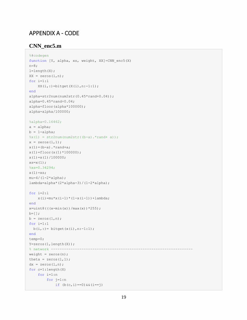
Ardu_Comp_Dec.m
ardu=serial('COM6','BaudRate',9600);
load ENC_DATA
enc_data=ENC_DATA;
fopen(ardu)
pause(5)
tic
flushinput(ardu)
out_data=[];
36
dec_data=[];
DEC_DATA=[];
for i=[1:10]
out_data=[enc_data(i,:) randi(255,1,4)];
fwrite(ardu,out_data);
pause(.5)
dec_data=fread(ardu,10);
Dec_Data=transpose(dec_data);
DEC_DATA(i,:)=Dec_Data;
end
time2=toc;
fclose(ardu)
save DEC_DATA DEC_DATA
encode_v4.ino #include <stdint.h>
#include <stdio.h>
#include <stdlib.h>
#include <math.h>
#include "R2.h"
#include "Enc2.h"
#include "Gdc1.h"
void setup(void) {
Serial.begin(9600);
}
//
void loop() {
char *array;
uint8_t dummyRead;
int da[8],jj,inclength=14,xlength=10;
float alpha,xs;
float send_data[xlength];
int sensor_data[xlength];
int inc_data[inclength];
int out_data[xlength];
int p,q,Pk,Phi,e,i,r,k,d,x;
char buffer[25]="";
// while(1){
if (Serial.available() > 0) {
for (int j=0;j<inclength;j++) { //read data from serial port into
inc_data[j]=Serial.read();
}
}
for(int j=0;j<xlength;j++) {
sensor_data[j]=inc_data[j];

37
}
for(int j=0;j<xlength;j++) { //initiallize empty send data into array
send_data[j]=0;
}
alpha=CNN_enc(sensor_data,send_data,xlength);
array=dtostrf(alpha,3,1,buffer);
jj=0;
while(*array!=0) {
dummyRead=*array; //dummyRead has byte of data pointed at by array pointer
da[jj]=*array;
jj++;
array++;
}
p=61;
q=53;
Pk=p*q;
Phi=(p-1)*(q-1);
x=2;
e=1;
while(x>1) {
e=e+1;
x=gcd(Phi,e);
}
i=1;
r=1;
while(r>0) {
k=(Phi*i)+1;
r=k%e;
i=i+1;
}
d=k/e;
for(int z=0;z<xlength;z++) {
out_data[z]=floor(send_data[z]+.5);
}
for(int z=0;z<xlength;z++) {
//Serial.println(inc_data[z]);
//Serial.write(sensor_data[z]);
//Serial.println(send_data[z]);
Serial.write(out_data[z]);
}
delay(500);
// }
}
enc2.c #include <stdint.h>

38
#include <stdio.h>
#include <stdlib.h>
#include <math.h>
#include <Arduino.h>
float CNN_enc (int D[], float Y[], int xlength) {
float alpha,a,b,lamda,mu,xs,x[xlength];
int k, Nb1[xlength][8],m,j,G,c,theta[xlength],xx[xlength], Nb2[xlength][8],dxx[xlength][8],S,
i,weight[8][8],dx[xlength][8] ;
//int D[10]={32, 31, 32, 32,33, 34,12,25,47,78}; //using GPIO input
for (m= 0; m< xlength; m++){
//Nb=D[m];
c=0x01;
for (j= 0; j< 8; j++)
{
G=(int)c&D[m];
if (G>0)
{
Nb1[m][j]=1;
}
else
{
Nb1[m][j]=0;
}
c = (c << 1);
}
} // XX=Nb1
//alpha=round((0.45*((double)rand() / (double)RAND_MAX)+0.04)*10000)/10000;
alpha=0.16462;
a = alpha;
b = 1-alpha;
x[0] = (b-a)*r2()+ a;
//x[0]=0.34294;
xs= x[0]; //update to pointer
mu=4/(1-2*alpha);
lamda=alpha*(2*alpha-3)/(1-2*alpha);
for (k= 1; k< xlength; k++){
x[k]=mu*x[k-1]*(1-x[k-1])+lamda;
}
float maxx = x[0];
float minx = x[0];
for (i = 0;i<xlength;i++) {
if (x[i]>maxx){
maxx = x[i];

39
}
if (x[i]<minx) {
minx = x[i];
}
}
for (k= 0; k< xlength; k++){
xx[k]=(uint8_t)(((x[k]-minx)/maxx)*255);
}
for (m= 0; m< xlength; m++){
//Nb=D[m];
c=0x01;
for (j= 0; j< 8; j++)
{
G=(int)c&D[m];
if (G>0)
{
Nb2[m][j]=1;
}
else
{
Nb2[m][j]=0;
}
c = (c << 1);
}
} // b=Nb200000000000
//network
for (m= 0; m< xlength; m++){
for (i= 0; i< 8; i++){
for (j= 0; j< 8;j++){
if ((Nb2[m][i]==0)&&(i==j)){
weight[i][j]=1;
}
else {
if ((Nb2[m][i]==1)&&(i==j))
{
weight[i][j]=-1;
}
else {
if (i!=j) {
weight[i][j]=0;
}
}
}
if (Nb2[m][i]==0){
theta[i]=-1/2;

40
}
else {
theta[i]=1/2;
}
}
}
for (i= 0; i< 8; i++){
S=theta[i];
for (j= 0; j< 8;j++){
S=S+weight[i][j]*Nb1[m][j];
}
if (S>=0){
dxx[m][i]=1;
}
else {
dxx[m][i]=0;
}
}
for (i= 0; i< 8; i++){
Y[m]=Y[m]+(dxx[m][i])*pow(2,(7-i));
}
}
return alpha, xs;
}
decode_v4.ino #include <stdint.h>
#include <stdio.h>
#include <stdlib.h>
#include <math.h>
#include "R2.h"
#include "Dec2.h"
#include "Gdc1.h"
void setup(void) {
Serial.begin(9600);
}
//
void loop() {
char *array;
uint8_t dummyRead;
int da[8],jj,inclength=14,xlength=10;
float alpha,xs;

41
float dec_data[xlength];
int enc_data[xlength];
int inc_data[inclength];
int out_data[xlength];
int p,q,Pk,Phi,e,i,r,k,d,x;
char buffer[25]="";
// while(1){
if (Serial.available() > 0) {
for (int j=0;j<inclength;j++) { //read data from serial port into
inc_data[j]=Serial.read();
}
}
for(int j=0;j<xlength;j++) {
enc_data[j]=inc_data[j];
}
for(int j=0;j<xlength;j++) { //initiallize empty send data into array
dec_data[j]=0;
}
alpha=CNN_dec(enc_data,dec_data,xlength);
array=dtostrf(alpha,3,1,buffer);
jj=0;
while(*array!=0) {
dummyRead=*array; //dummyRead has byte of data pointed at by array pointer
da[jj]=*array;
jj++;
array++;
}
p=61;
q=53;
Pk=p*q;
Phi=(p-1)*(q-1);
x=2;
e=1;
while(x>1) {
e=e+1;
x=gcd(Phi,e);
}
i=1;
r=1;
while(r>0) {
k=(Phi*i)+1;
r=k%e;
i=i+1;
}
d=k/e;
for(int z=0;z<xlength;z++) {
42
out_data[z]=floor(dec_data[z]+.5);
}
for(int z=0;z<xlength;z++) {
//Serial.println(inc_data[z]);
//Serial.println(enc_data[z]);
//Serial.println(dec_data[z]);
Serial.write(out_data[z]);
}
delay(500);
// }
}
dec2.c #include <stdint.h>
#include <stdio.h>
#include <stdlib.h>
#include <math.h>
float CNN_dec (int D[], float Y[], int xlength) {
float alpha,a,b,lamda,mu,xs,x[xlength];
int k, Nb1[xlength][8],m,j,G,c,theta[xlength],xx[xlength], Nb2[xlength][8],dxx[xlength][8],S,
i,weight[8][8],dx[xlength][8] ;
//int D[10]={32, 31, 32, 32,33, 34,12,25,47,78}; //using GPIO input
for (m= 0; m< xlength; m++){
//Nb=D[m];
c=0x01;
for (j= 0; j< 8; j++)
{
G=c&D[m];
if (G>0)
{
Nb1[m][j]=1;
}
else
{
Nb1[m][j]=0;
}
c = (c << 1);
}
} // XX=Nb1
//alpha=alpha;
alpha=0.16462;
a = alpha;
b = 1-alpha;
x[0] = x[0];
xs= x[0]; //update to pointer

43
mu=4/(1-2*alpha);
lamda=alpha*(2*alpha-3)/(1-2*alpha);
for (k= 1; k< xlength; k++){
x[k]=mu*x[k-1]*(1-x[k-1])+lamda;
}
float maxx = x[0];
float minx = x[0];
for (i = 0;i<xlength;i++) {
if (x[i]>maxx){
maxx = x[i];
}
if (x[i]<minx) {
minx = x[i];
}
}
for (k= 0; k< xlength; k++){
xx[k]=(uint8_t)(((x[k]-minx)/maxx)*255);
}
for (m= 0; m< xlength; m++){
//Nb=D[m];
c=0x01;
for (j= 0; j< 8; j++)
{
G=c&D[m];
if (G>0)
{
Nb2[m][j]=1;
}
else
{
Nb2[m][j]=0;
}
c = (c << 1);
}
} // b=Nb2
//network
for (m= 0; m< xlength; m++){
for (i= 0; i< 8; i++){
for (j= 0; j< 8;j++){
if ((Nb2[m][i]==0)&&(i==j)){
weight[i][j]=1;
}
else {

44
if ((Nb2[m][i]==1)&&(i==j))
{
weight[i][j]=-1;
}
else {
if (i!=j) {
weight[i][j]=0;
}
}
}
if (Nb2[m][i]==0){
theta[i]=-1/2;
}
else {
theta[i]=1/2;
}
}
}
for (i= 0; i< 8; i++){
S=theta[i];
for (j= 0; j< 8;j++){
S=S+weight[i][j]*Nb1[m][j];
}
if (S>=0){
dxx[m][i]=1;
}
else {
dxx[m][i]=0;
}
}
for (i= 0; i< 8; i++){
Y[m]=Y[m]+(dxx[m][i])*pow(2,(7-i));
}
}
return alpha, xs;
}
r2.c #include <stdlib.h>
double r2()
{
return (double)rand() / (double)RAND_MAX;
}
gdc1.c

45
int gcd ( int a, int b )
{
int c;
while ( a != 0 ) {
c = a; a = b%a; b = c;
}
return b;
}

46
APPENDIX B – ADDITIONAL FIGURES
Figure 9: Result of Wavelet Decomposition Encryption of 369 kB Image – Level 1
Figure 10: Result of Wavelet Decomposition Encryption of 13 kB Image – Level 1
Figure 11: Result of Wavelet Decomposition Encryption of 96 kB Image – Level 1

47
Figure 12: Result of Wavelet Decomposition Encryption of 96 kB Image – Level 2
Figure 13: Result of Wavelet Decomposition Encryption of 96 kB Image – Level 3
Figure 14: Result of Wavelet Decomposition Encryption of 96 kB Image – Level 4
48
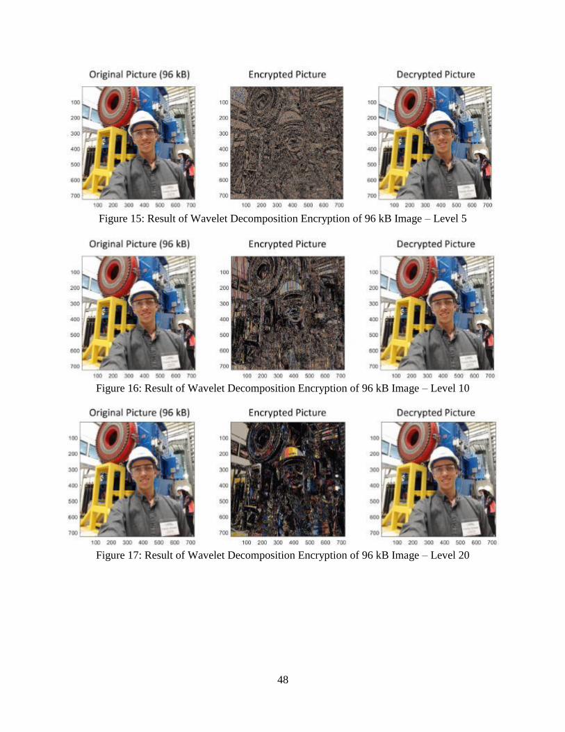
Figure 15: Result of Wavelet Decomposition Encryption of 96 kB Image – Level 5
Figure 16: Result of Wavelet Decomposition Encryption of 96 kB Image – Level 10
Figure 17: Result of Wavelet Decomposition Encryption of 96 kB Image – Level 20

49
Figure 18: Graph of 1,000 Data Points Encrypted and Decrypted by Arduino
Figure 19: Graph of 10,000 Data Points Encrypted and Decrypted by Arduino

50
WORKS CITED
[1] Hawk, Carol and Akhlesh Kaushiva. “Cybersecurity and the Smarter Grid.” The Electricity
Journal 27.4 (2014): 84 – 95. Print.
[4,2] Dubai Municipality. (2017, Oct. 25) Smart Dubai. Retrieved from
http://www.smartdubai.ae/ foundation_vision.php
[5,3] Amsterdam Smart City. (2017, Nov 1) amsterdam smart city. Retrieved from
https://amsterdamsmartcity.com/
[6,4] Hsu, Chin-Lung, and Judy Chuan-Chuan Lin. “An empirical examination of consumer
adoption of Internet of Things services: Network externalities and concern for
information privacy perspectives.” Computers in Human Behavior 62 (2016): 516-527.
Print.
[19,5] Wisse, Peter. Metapattern: Context and Time in Information Models. New York: Addison-
Wesley, 2001. Print
[11,6] Wakerly. John F. Digital Design Principles and Practices, 4th ed. New Jersey: Pearson,
2006. Print.
[14,7] Microchip Direct. (2016, Nov 15) Microchip Direct. Retrieved from
https://www.microchipdirect.com/
[2,8] Ashok, Aditya, Adam Hahn, and Manimaran Govindarasu. “Cyber-physical security of
Wide-Area Monitoring, Protection and Control in a smart grid environment.” Journal of
Advanced Research 5.4 (2014): 481-489. Print.
[12,9] Public Utilities Commission of Hawaii. (2017, Nov 3) PUC Annual Report Fiscal Year
2016. Retrieved from https://puc.hawaii.gov/wp-content/uploads/2013/04/PUC-Annual-
Report-Fiscal-Year-2016.pdf
[15,10] Honolulu Star Advertiser. (2017, Nov 25) Full Senate Votes 16-9 in Support of Oahu
Rail Bailout. Retrieved from http://www.staradvertiser.com/2017/08/30/breaking-
news/full-senate-votes-16-9-in-support-of-oahu-rail-bailout/
[13,11] Public Utilities Commission of Hawaii. (2017, Nov 3) Public Utilities Commission.
Retrieved from http://puc.hawaii.gov/
[3,12] Jahan, Israt, Asif Mohammad, and Liton Jude Rozario. “Improved RSA cryptosystem
based on the study of number theory and public key cryptosystems.” American Journal of
Engineering Research 4.1 (2015): 143-149. Print.
[17,13] Business Source Complete. “Internet billing system uses RSA encryption.” American
Banker 164.27 (1999): 18. Print.
[18,14] Integrated Technologies of America. “File security uses smartcard and RSA encryption.”
Network Security 1997.4 (1997): 5. Print.
[7,15] Kleinjung, Thorsten, et all. “Factorization of 768-bit RSA modulus.” Cryptology ePrint
Archive 6 (2010): Print.
[8,16] Dixon, Brandon, and Arjen Lenstra. “Factoring Integers Using SIMD Sieves.” Conference
Paper, 2001. Print.
[9,17] Su, Scott, Alvin Lin, and Jui-Cheng Yen. “Design and Realization of A New Chaotic
Neural Encryption/Decryption Network.” Circuits and Systems, 2000. Print.
[16,18] Department of Homeland Security. (2017, Oct 13) Recommended Practice: Improving
Industrial Control System Cybersecurity with Defense-in-Depth Strategies. Retrieved
from https://ics-cert.us-cert.gov/sites/default/files/recommended_practices/NCCIC_ICS-
CERT_Defense_in_Depth_2016_S508C.pdf

51
[10,19] PBS. (2016, Oct 22) NOVA: CyberWar Threat. Retrieved from
http://www.pbs.org/wgbh/nova/military/cyberwar-threat.html