Stochastic learning feedback hybrid automata for dynamic power management in embedded systems
Upload
westernsydneyCategory
view
0download
0
MASTER’S (MSc) GRADUATE THESIS
Title:
Study and project calculations of
a hybrid pile or other embedded
structure in soil

Thesis author :
HESAM RAHNAMA Thesis supervisor :
Prof. Włodzimierz BRZĄKAŁA Thesis reviewer :
Prof. Wojciech PULA
Academic year
2013/2014
Feb 2014

General Characteristics
• Categorized as DEEP foundation.
• Consisting of 2 different portions, one of D1 diameter and the other one of D2 diameter. (D1>D2)
• Intended to bear lateral load aiming specifically to minimize the Max lateral displacement on the top.

Analytical Scopes
• Solved based on Classical method of Winkler.
• Assumed as a finite beam leaned on an elastic support (referred to as subgrade/subsoil in Winkler definition).
• Analysis solved by means of Maple.17

Analytical Scopes
• 𝑬𝑰.𝒅𝟒𝒚
𝒅𝒙𝟒 + ₵. 𝑩. 𝒚 𝒙 = 𝒒𝟎(𝒙) ;
No uniform load → 𝑞0 𝑥 = 0 ; So, the general solution is :
• 𝒚 𝒙 = 𝒆𝒙
𝒍𝒘 𝑪𝟏. 𝑪𝒐𝒔 𝒙
𝒍𝒘+ 𝑪𝟐. 𝑺𝒊𝒏
𝒙
𝒍𝒘+ 𝒆
− 𝒙
𝒍𝒘 𝑪𝟑. 𝑪𝒐𝒔 𝒙
𝒍𝒘+ 𝑪𝟒. 𝑺𝒊𝒏
𝒙
𝒍𝒘
Where:
𝑙𝑤 ∶(Characteristic length of the pile) = 4𝐸𝐼
₵.𝐵
4 , [𝑚]
₵ : ( Coefficient of elastic subsoil) , [ 𝑀𝑁
𝑚3]
𝐶𝑖: (Integration coefficients)

Influential terms on the displacement function
1- ″EI ″ ( Stiffness)
Depending on geometry ( I )
Mechanical characteristics of construction material (E).
2- "₵“ - depending on soil characteristics. ₵ =𝑟
𝑦

Influential terms on the displacement function
Due to :
• Pretty complex mathematical calculations
• Trigonometric functions
𝑙𝑤 =4𝑬𝑰
₵ . 𝐵
4 ; 𝑦 𝑥 = 𝑒
𝑥
𝒍𝒘 𝐶1 𝐜𝐨𝐬𝒙
𝒍𝒘+ 𝐶2 𝐬𝐢𝐧
𝒙
𝒍𝒘+ 𝑒
− 𝑥
𝒍𝒘 𝐶3 𝐜𝐨𝐬𝒙
𝒍𝒘+ 𝐶4 𝐬𝐢𝐧
𝒙
𝒍𝒘
Precise calculation needed to determine the dominant term and influence

Analysis – Continuity conditions
• Analytical modeling leading to a system of 8 questions and 8 unknowns.
M= -EI . [𝐶1, 𝐶2, 𝐶3, 𝐶4].𝑑𝑦2
𝑑𝑥2 ;
θ=[𝐶1, 𝐶2, 𝐶3, 𝐶4].𝑑𝑦
𝑑𝑥
So,
Number of 𝑪𝒊 : 4 x 2 ( Left – Right) = 8
M=8 number of Unknowns
Q= -EI . [𝐶1, 𝐶2, 𝐶3, 𝐶4].𝑑𝑦3
𝑑𝑥3
Y =[𝐶1, 𝐶2, 𝐶3, 𝐶4]. 𝑦
N=8 number of Equations

Testing Analysis procedure
Test 1
Test 2
40 x 40 cm
40 x 40 cm 20 x 20 cm
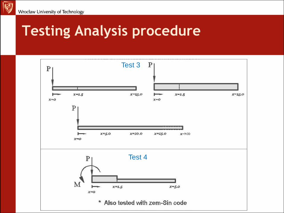
Testing Analysis procedure
Test 3
Test 4

Determining “₵”
• Terzaghi’s Method;
¢ℎ = 𝑛ℎ .𝑧
𝐵
Where:
• ₵: 𝐶𝑜𝑒𝑓𝑓𝑖𝑐𝑖𝑒𝑛𝑡 𝑜𝑓 𝑠𝑢𝑏𝑔𝑟𝑎𝑑𝑒 𝑟𝑒𝑎𝑐𝑡𝑖𝑜𝑛 𝑜𝑓 𝑠𝑜𝑖𝑙
• 𝒏𝒉: 𝑟𝑎𝑡𝑒 𝑜𝑓 𝑡ℎ𝑒 𝑖𝑛𝑐𝑟𝑒𝑎𝑠𝑒 𝑜𝑓 𝑡ℎ𝑒 𝑐𝑜𝑒𝑓𝑓𝑖𝑐𝑖𝑒𝑛𝑡
• 𝑜𝑓 ℎ𝑜𝑟𝑖𝑧𝑜𝑛𝑡𝑎𝑙 𝑠𝑢𝑏𝑔𝑟𝑎𝑑𝑒 𝑟𝑒𝑎𝑐𝑡𝑖𝑜𝑛
• 𝒁: 𝑑𝑒𝑝𝑡ℎ 𝑜𝑓 𝑎 𝑔𝑖𝑣𝑒𝑛 𝑠𝑒𝑐𝑡𝑖𝑜𝑛 𝑓𝑟𝑜𝑚 𝑓𝑖𝑛𝑖𝑠ℎ𝑒𝑑
𝑔𝑟𝑎𝑑𝑒 (Soil).
In this method, ¢ is highly
dependent on depth(z) .
• Polish code - PN-83/B-02482
for non-Cohesive soil (sand):
𝐾𝑥 = 𝑆𝑛 . 0,75. 𝐼𝐷2 + 0,225. 𝐼𝐷 + 0,150 .
𝛾
𝐷
(𝒌𝒙 ≣ ₵)
Where:
• 𝑰𝑫 : density index, 0.2 < ID < 1
• D : Diameter of the pile [m],D>0,2m;D=1,0m if
D>1,0m
• : Unit weight of the soil [kN/𝑚3],
• 𝑺𝒏: 1.101.20 if piling improves the soil (driven
piles in cohesion-less soil, especially loose ones)
𝑺𝒏: 0.800.90 if piling weakens the soil (bored-
piles, possibility of soil loosening not eliminated).

Generalization of the method
𝑁 = 2 + 𝑛 − 1 ∗ 4 + 2
N : Number of Unknowns
Can be applied in order to calculate multi-section hybrid foundation beams with different stiffness and different subsoil layers.

Application-Calculation part
1) Retaining walls’ support 2) Secant pile wall

Designing Approach
Reasonable 𝐿1
𝐿 regarding Maximum Displacement

Design Calculation
• ₵ : 20 MN
m3
• 𝑬𝑪𝒐𝒏𝒄. ∶ 30𝑀𝑃𝑎
• Soil : Dray Sand
• ɣ : 1,35 (Magnifications load factor)
• Standard:
EC 2 - CEN EN1992-1-1

Design Values
240
161
0.0
1.0
2.0
3.0
4.0
5.0
6.0
0 50 100 150 200 250
Pil
e d
ep
th-m
Moment-KN.m
74, 3
0
1
2
3
4
5
6
-100 -50 0 50 100
Pil
e l
en
gth
-m
Shearing force-KN

Drawing
• More details available on the
plotted drawing

Fin
H.Rahnama
Feb 2014-Wroclaw
Copyright © 2022 FDOKUMEN