CX2500-0020 - Audio Interface - download - Beckhoff
29
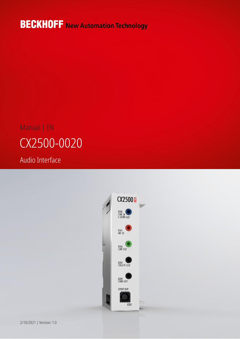
Manual | EN CX2500-0020 Audio Interface 2/10/2021 | Version: 1.0
-
Upload
khangminh22 -
Category
Documents
-
view
0 -
download
0
Transcript of CX2500-0020 - Audio Interface - download - Beckhoff
Manual | EN
CX2500-0020Audio Interface
2/10/2021 | Version: 1.0

Inhaltsverzeichnis
CX2500-0020 3Version: 1.0
Inhaltsverzeichnis1 Foreword .................................................................................................................................................... 5
1.1 Notes on the documentation.............................................................................................................. 51.2 Safety instructions ............................................................................................................................. 61.3 Documentation issue state ................................................................................................................ 7
2 Product overview....................................................................................................................................... 82.1 Intended use...................................................................................................................................... 82.2 System overview ............................................................................................................................... 92.3 Technical data ................................................................................................................................... 9
3 Mounting and wiring................................................................................................................................ 103.1 Unpacking, installation and transport .............................................................................................. 103.2 Dimensions...................................................................................................................................... 113.3 Attaching the system interface to the CX20x0 system .................................................................... 123.4 Installation on the mounting rail ....................................................................................................... 133.5 Mounting the module lock................................................................................................................ 153.6 Connections..................................................................................................................................... 17
4 Commissioning / Configuration ............................................................................................................. 214.1 Switching on and off ........................................................................................................................ 21
5 Error handling and diagnostics.............................................................................................................. 225.1 Faults ............................................................................................................................................... 225.2 Realtek Audio Manager faults ......................................................................................................... 22
6 Decommissioning.................................................................................................................................... 246.1 Disassembly and disposal ............................................................................................................... 24
7 Appendix .................................................................................................................................................. 267.1 Certifications.................................................................................................................................... 267.2 Support and Service ........................................................................................................................ 27
Inhaltsverzeichnis
CX2500-00204 Version: 1.0
Foreword
CX2500-0020 5Version: 1.0
1 Foreword
1.1 Notes on the documentationThis description is only intended for the use of trained specialists in control and automation engineering whoare familiar with applicable national standards.It is essential that the documentation and the following notes and explanations are followed when installingand commissioning the components. It is the duty of the technical personnel to use the documentation published at the respective time of eachinstallation and commissioning.
The responsible staff must ensure that the application or use of the products described satisfy all therequirements for safety, including all the relevant laws, regulations, guidelines and standards.
Disclaimer
The documentation has been prepared with care. The products described are, however, constantly underdevelopment.We reserve the right to revise and change the documentation at any time and without prior announcement.No claims for the modification of products that have already been supplied may be made on the basis of thedata, diagrams and descriptions in this documentation.
Trademarks
Beckhoff®, TwinCAT®, EtherCAT®, EtherCAT G®, EtherCAT G10®, EtherCAT P®, Safety over EtherCAT®,TwinSAFE®, XFC®, XTS® and XPlanar® are registered trademarks of and licensed by Beckhoff AutomationGmbH.Other designations used in this publication may be trademarks whose use by third parties for their ownpurposes could violate the rights of the owners.
Patent Pending
The EtherCAT Technology is covered, including but not limited to the following patent applications andpatents:EP1590927, EP1789857, EP1456722, EP2137893, DE102015105702with corresponding applications or registrations in various other countries.
EtherCAT® is a registered trademark and patented technology, licensed by Beckhoff Automation GmbH,Germany
Copyright
© Beckhoff Automation GmbH & Co. KG, Germany.The reproduction, distribution and utilization of this document as well as the communication of its contents toothers without express authorization are prohibited.Offenders will be held liable for the payment of damages. All rights reserved in the event of the grant of apatent, utility model or design.
Foreword
CX2500-00206 Version: 1.0
1.2 Safety instructions
Safety regulations
Please note the following safety instructions and explanations!Product-specific safety instructions can be found on following pages or in the areas mounting, wiring,commissioning etc.
Exclusion of liability
All the components are supplied in particular hardware and software configurations appropriate for theapplication. Modifications to hardware or software configurations other than those described in thedocumentation are not permitted, and nullify the liability of Beckhoff Automation GmbH & Co. KG.
Personnel qualification
This description is only intended for trained specialists in control, automation and drive engineering who arefamiliar with the applicable national standards.
Description of symbols
In this documentation the following symbols are used with an accompanying safety instruction or note. Thesafety instructions must be read carefully and followed without fail!
DANGERSerious risk of injury!Failure to follow the safety instructions associated with this symbol directly endangers the life and health ofpersons.
WARNINGRisk of injury!Failure to follow the safety instructions associated with this symbol endangers the life and health of per-sons.
CAUTIONPersonal injuries!Failure to follow the safety instructions associated with this symbol can lead to injuries to persons.
NOTEDamage to the environment or devicesFailure to follow the instructions associated with this symbol can lead to damage to the environment orequipment.
Tip or pointerThis symbol indicates information that contributes to better understanding.
Foreword
CX2500-0020 7Version: 1.0
1.3 Documentation issue stateVersion Changes1.0 Release version
Product overview
CX2500-00208 Version: 1.0
2 Product overview
2.1 Intended useThe CX20x0 device series is a modular control system designed for DIN rail installation. The system isscalable, so that the required modules can be assembled and installed in the control cabinet or terminal boxas required.
Only switch the PC off after closing the software
Before the Embedded PC is switched off, the software currently running on it should be stopped properly inorder to avoid data loss on the hard disk. Please read the section on “Switching off”.
Switch off all system components and uncouple the Industrial PC from the system if the PC is not used forcontrol purposes, e.g. during a function test. To disconnect first pull the first terminal behind the powersupply unit (optional), then pull the connectors of the fieldbus connections.System components that have been switched off must be secured against being switched on again.
The Embedded PC’s power supply unit must be supplied with 24 VDC.
NOTEDamage to the environment or devicesDo not exchange any parts when under power! The exchange of controller parts when live can lead toshort-circuits or overvoltages. These can damage the controller itself and connected peripherals (terminals,monitors, input devices, etc.).
When components are being fitted or removed, the supply voltage must be switched off.
Software knowledge
NOTESystem malfunctionsMandatory software knowledge! Every user must be familiar with any of the functions of the software in-stalled on the PC that he can reach.
Product overview
CX2500-0020 9Version: 1.0
2.2 System overview
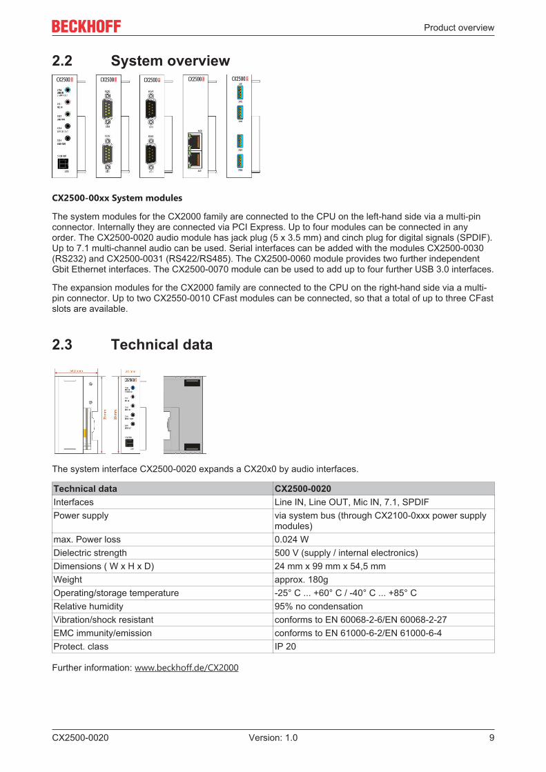
CX2500-00xx System modules
The system modules for the CX2000 family are connected to the CPU on the left-hand side via a multi-pinconnector. Internally they are connected via PCI Express. Up to four modules can be connected in anyorder. The CX2500-0020 audio module has jack plug (5 x 3.5 mm) and cinch plug for digital signals (SPDIF).Up to 7.1 multi-channel audio can be used. Serial interfaces can be added with the modules CX2500-0030(RS232) and CX2500-0031 (RS422/RS485). The CX2500-0060 module provides two further independentGbit Ethernet interfaces. The CX2500-0070 module can be used to add up to four further USB 3.0 interfaces.
The expansion modules for the CX2000 family are connected to the CPU on the right-hand side via a multi-pin connector. Up to two CX2550-0010 CFast modules can be connected, so that a total of up to three CFastslots are available.
2.3 Technical data
The system interface CX2500-0020 expands a CX20x0 by audio interfaces.
Technical data CX2500-0020Interfaces Line IN, Line OUT, Mic IN, 7.1, SPDIFPower supply via system bus (through CX2100-0xxx power supply
modules)max. Power loss 0.024 WDielectric strength 500 V (supply / internal electronics)Dimensions ( W x H x D) 24 mm x 99 mm x 54,5 mmWeight approx. 180gOperating/storage temperature -25° C ... +60° C / -40° C ... +85° CRelative humidity 95% no condensationVibration/shock resistant conforms to EN 60068-2-6/EN 60068-2-27EMC immunity/emission conforms to EN 61000-6-2/EN 61000-6-4Protect. class IP 20
Further information: www.beckhoff.de/CX2000
Mounting and wiring
CX2500-002010 Version: 1.0
3 Mounting and wiring
3.1 Unpacking, installation and transportThe specified storage conditions must be adhered to (see "Technical data").
Dimensions and weight of the individual modules
Dimensions (W x H x D): 24 mm x 100 mm x 55 mm
Weight: approx. 180 g (system interface)
Unpacking
Proceed as follows to unpack the unit:
1. Remove packaging.2. Do not discard the original packaging. Keep it for transporting the device in the future.3. Check the delivery for completeness by comparing it with your order.4. Please keep the associated paperwork. It contains important information for handling the unit.5. Check the contents for visible shipping damage.6. If you notice any shipping damage or inconsistencies between the contents and your order, you
should notify Beckhoff Service.
NOTEDanger of damage to the device!During transport in cold conditions, or if the device is subjected to extreme temperature differences, con-densation on and inside the device must be avoided. Prior to operation, the device must be allowed toslowly adjust to room temperature. Should condensation occur, a delay time of approximately 12 hoursmust be allowed before the unit is switched on.
Installation
The devices are designed for installation in control cabinets.
Shipping and relocation
Despite the robust design of the unit, the components are sensitive to strong vibrations and impacts. Duringtransport, your computer should therefore be protected from excessive mechanical stress. Therefore, pleaseuse the original packaging.
Mounting and wiring
CX2500-0020 11Version: 1.0
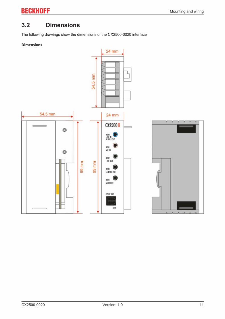
3.2 DimensionsThe following drawings show the dimensions of the CX2500-0020 interface
Dimensions
Mounting and wiring
CX2500-002012 Version: 1.0
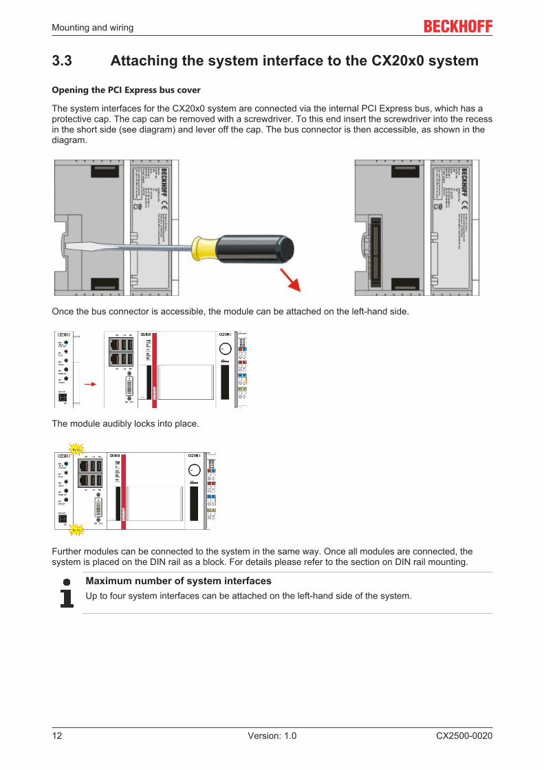
3.3 Attaching the system interface to the CX20x0 system
Opening the PCI Express bus cover
The system interfaces for the CX20x0 system are connected via the internal PCI Express bus, which has aprotective cap. The cap can be removed with a screwdriver. To this end insert the screwdriver into the recessin the short side (see diagram) and lever off the cap. The bus connector is then accessible, as shown in thediagram.
Once the bus connector is accessible, the module can be attached on the left-hand side.
The module audibly locks into place.
Further modules can be connected to the system in the same way. Once all modules are connected, thesystem is placed on the DIN rail as a block. For details please refer to the section on DIN rail mounting.
Maximum number of system interfacesUp to four system interfaces can be attached on the left-hand side of the system.
Mounting and wiring
CX2500-0020 13Version: 1.0
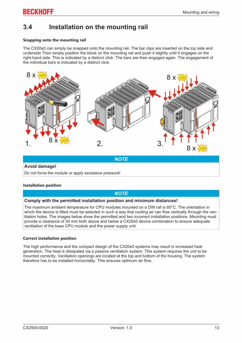
3.4 Installation on the mounting rail
Snapping onto the mounting rail
The CX20x0 can simply be snapped onto the mounting rail. The bar clips are inserted on the top side andunderside Then simply position the block on the mounting rail and push it slightly until it engages on theright-hand side. This is indicated by a distinct click. The bars are then engaged again. The engagement ofthe individual bars is indicated by a distinct click.
NOTEAvoid damage!Do not force the module or apply excessive pressure!
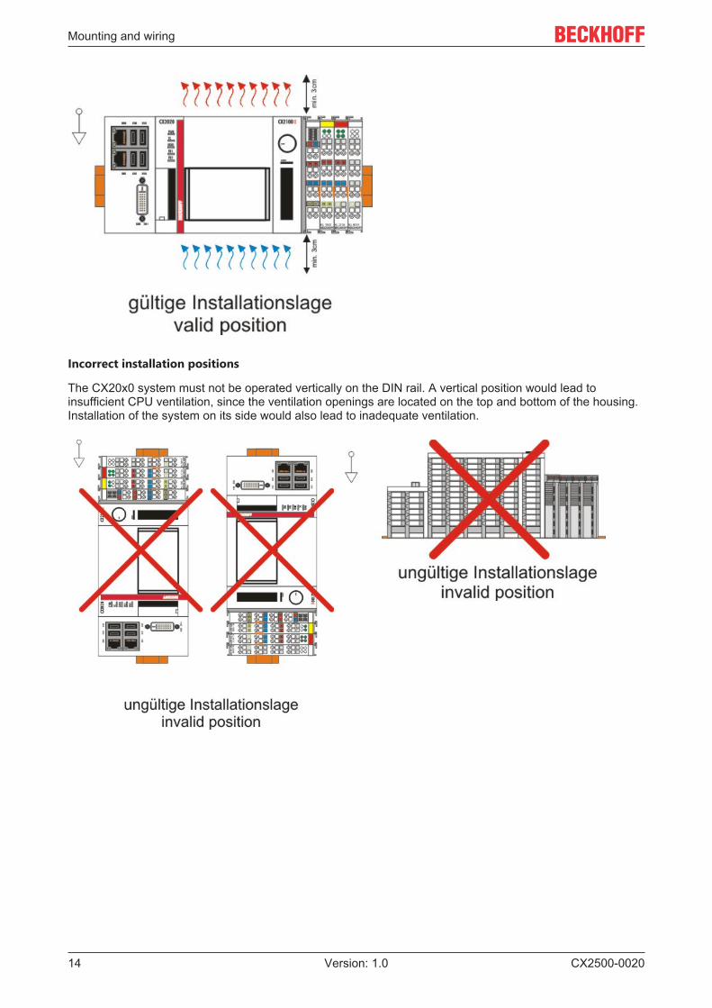
Installation position
NOTEComply with the permitted installation position and minimum distances!The maximum ambient temperature for CPU modules mounted on a DIN rail is 60°C. The orientation inwhich the device is fitted must be selected in such a way that cooling air can flow vertically through the ven-tilation holes. The images below show the permitted and two incorrect installation positions. Mounting mustprovide a clearance of 30 mm both above and below a CX20x0 device combination to ensure adequateventilation of the base CPU module and the power supply unit.
Correct installation position
The high performance and the compact design of the CX20x0 systems may result in increased heatgeneration. The heat is dissipated via a passive ventilation system. This system requires the unit to bemounted correctly. Ventilation openings are located at the top and bottom of the housing. The systemtherefore has to be installed horizontally. This ensures optimum air flow.
Mounting and wiring
CX2500-002014 Version: 1.0
Incorrect installation positions
The CX20x0 system must not be operated vertically on the DIN rail. A vertical position would lead toinsufficient CPU ventilation, since the ventilation openings are located on the top and bottom of the housing.Installation of the system on its side would also lead to inadequate ventilation.
Mounting and wiring
CX2500-0020 15Version: 1.0
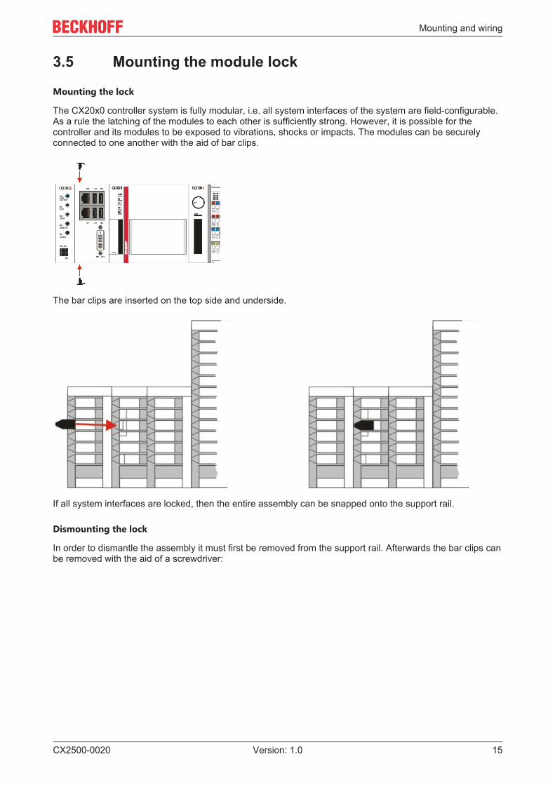
3.5 Mounting the module lock
Mounting the lock
The CX20x0 controller system is fully modular, i.e. all system interfaces of the system are field-configurable.As a rule the latching of the modules to each other is sufficiently strong. However, it is possible for thecontroller and its modules to be exposed to vibrations, shocks or impacts. The modules can be securelyconnected to one another with the aid of bar clips.
The bar clips are inserted on the top side and underside.
If all system interfaces are locked, then the entire assembly can be snapped onto the support rail.
Dismounting the lock
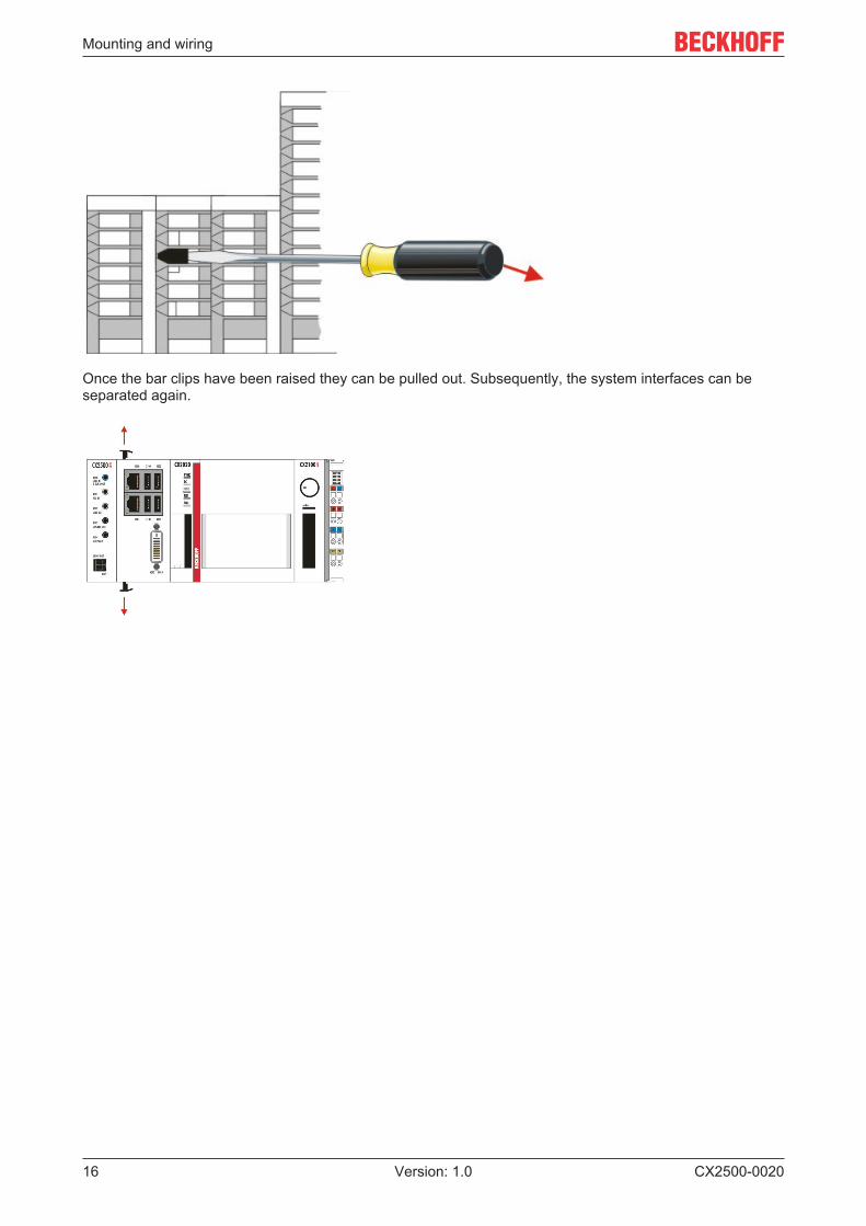
In order to dismantle the assembly it must first be removed from the support rail. Afterwards the bar clips canbe removed with the aid of a screwdriver:
Mounting and wiring
CX2500-002016 Version: 1.0
Once the bar clips have been raised they can be pulled out. Subsequently, the system interfaces can beseparated again.
Mounting and wiring
CX2500-0020 17Version: 1.0
3.6 Connections
Adjusting the BIOS settingAfter connecting the hardware, change the Azalia configuration from DISABLED to ENABLED in theBIOS chipset to make sure the interface is detected. Further information can be found in the BIOSdescription of the CX2000 documentation.
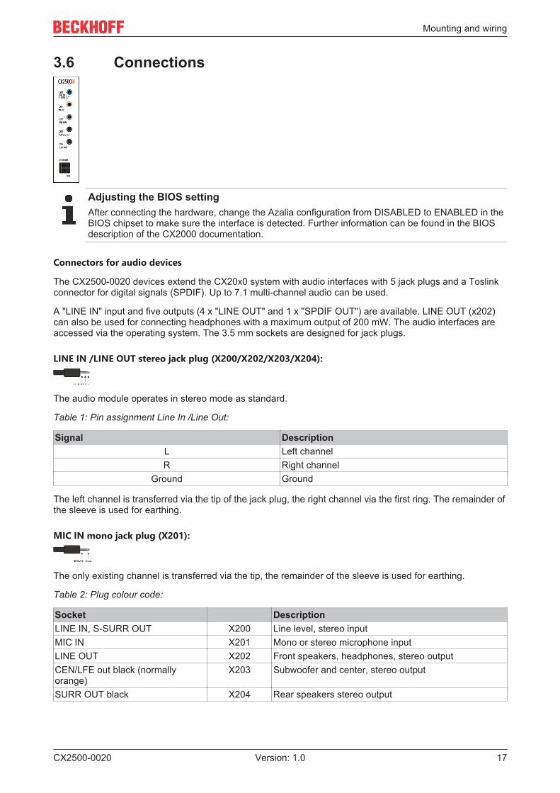
Connectors for audio devices
The CX2500-0020 devices extend the CX20x0 system with audio interfaces with 5 jack plugs and a Toslinkconnector for digital signals (SPDIF). Up to 7.1 multi-channel audio can be used.
A "LINE IN" input and five outputs (4 x "LINE OUT" and 1 x "SPDIF OUT") are available. LINE OUT (x202)can also be used for connecting headphones with a maximum output of 200 mW. The audio interfaces areaccessed via the operating system. The 3.5 mm sockets are designed for jack plugs.
LINE IN /LINE OUT stereo jack plug (X200/X202/X203/X204):
The audio module operates in stereo mode as standard.
Table 1: Pin assignment Line In /Line Out:
Signal DescriptionL Left channelR Right channel
Ground Ground
The left channel is transferred via the tip of the jack plug, the right channel via the first ring. The remainder ofthe sleeve is used for earthing.
MIC IN mono jack plug (X201):
The only existing channel is transferred via the tip, the remainder of the sleeve is used for earthing.
Table 2: Plug colour code:
Socket DescriptionLINE IN, S-SURR OUT X200 Line level, stereo inputMIC IN X201 Mono or stereo microphone inputLINE OUT X202 Front speakers, headphones, stereo outputCEN/LFE out black (normallyorange)
X203 Subwoofer and center, stereo output
SURR OUT black X204 Rear speakers stereo output
Mounting and wiring
CX2500-002018 Version: 1.0
SPDIF OUT (x205):
TOSLINK connector for digital signals.
Configuration with the Realtek HD Audio Manager:
Various audio settings are available for improving the sound quality. The Manager is called up via thetaskbar. Right-click on the speaker symbol and open the sound manager.
The tab show all playback and recording devices connected with the CX. The orange tick defines therespective device as standard device. This can be changed under "Set default Device" . Furtherapplications (e.g. multi-streaming playback/record) can be found under "Device extended settings ".
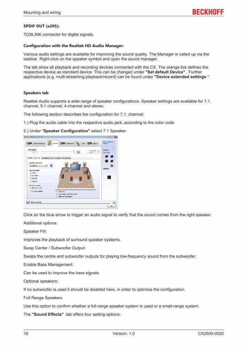
Speakers tab
Realtek Audio supports a wide range of speaker configurations. Speaker settings are available for 7.1.channel, 5.1 channel, 4-channel and stereo.
The following section describes the configuration for 7.1. channel:
1.) Plug the audio cable into the respective audio jack, according to the color code.
2.) Under "Speaker Configuration" select 7.1 Speaker:
Click on the blue arrow to trigger an audio signal to verify that the sound comes from the right speaker.
Additional options:
Speaker Fill:
Improves the playback of surround speaker systems.
Swap Center / Subwoofer Output:
Swaps the centre and subwoofer outputs for playing low-frequency sound from the subwoofer.
Enable Bass Management:
Can be used to improve the bass signals.
Optional speakers:
If no subwoofer is used it should be disabled here, in order to optimize the configuration.
Full Range Speakers
Use this option to confirm whether a full-range speaker system is used or a small-range system.
The "Sound Effects" tab offers four setting options:
Mounting and wiring
CX2500-0020 19Version: 1.0
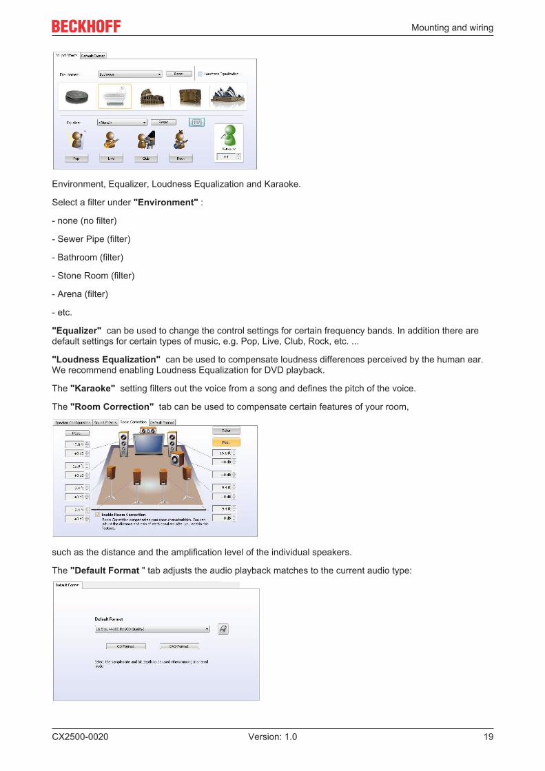
Environment, Equalizer, Loudness Equalization and Karaoke.
Select a filter under "Environment" :
- none (no filter)
- Sewer Pipe (filter)
- Bathroom (filter)
- Stone Room (filter)
- Arena (filter)
- etc.
"Equalizer" can be used to change the control settings for certain frequency bands. In addition there aredefault settings for certain types of music, e.g. Pop, Live, Club, Rock, etc. ...
"Loudness Equalization" can be used to compensate loudness differences perceived by the human ear.We recommend enabling Loudness Equalization for DVD playback.
The "Karaoke" setting filters out the voice from a song and defines the pitch of the voice.
The "Room Correction" tab can be used to compensate certain features of your room,
such as the distance and the amplification level of the individual speakers.
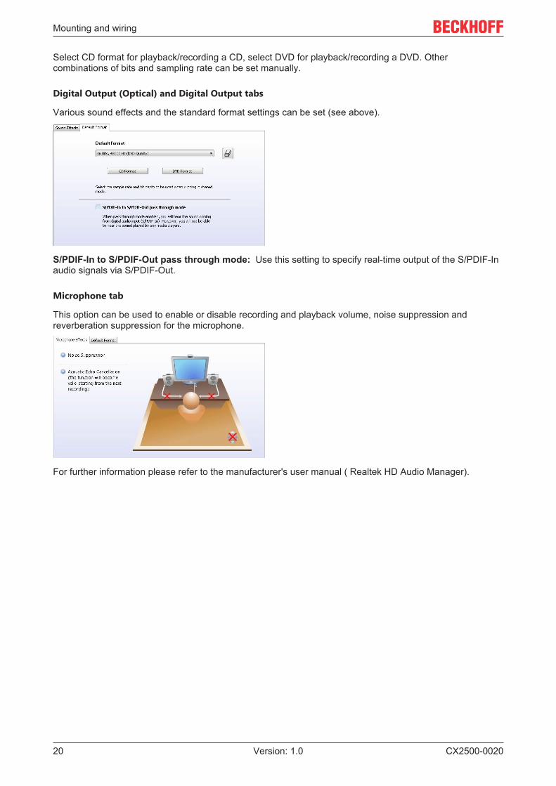
The "Default Format " tab adjusts the audio playback matches to the current audio type:
Mounting and wiring
CX2500-002020 Version: 1.0
Select CD format for playback/recording a CD, select DVD for playback/recording a DVD. Othercombinations of bits and sampling rate can be set manually.
Digital Output (Optical) and Digital Output tabs
Various sound effects and the standard format settings can be set (see above).
S/PDIF-In to S/PDIF-Out pass through mode: Use this setting to specify real-time output of the S/PDIF-Inaudio signals via S/PDIF-Out.
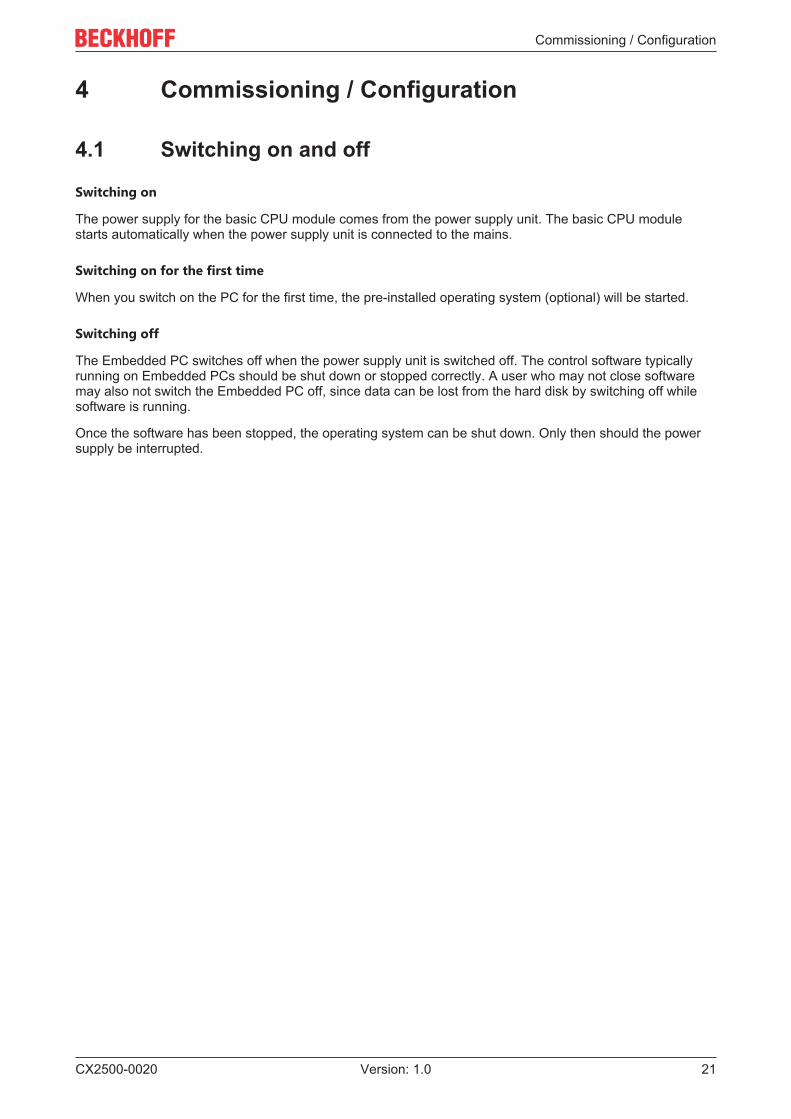
Microphone tab
This option can be used to enable or disable recording and playback volume, noise suppression andreverberation suppression for the microphone.
For further information please refer to the manufacturer's user manual ( Realtek HD Audio Manager).
Commissioning / Configuration
CX2500-0020 21Version: 1.0
4 Commissioning / Configuration
4.1 Switching on and off
Switching on
The power supply for the basic CPU module comes from the power supply unit. The basic CPU modulestarts automatically when the power supply unit is connected to the mains.
Switching on for the first time
When you switch on the PC for the first time, the pre-installed operating system (optional) will be started.
Switching off
The Embedded PC switches off when the power supply unit is switched off. The control software typicallyrunning on Embedded PCs should be shut down or stopped correctly. A user who may not close softwaremay also not switch the Embedded PC off, since data can be lost from the hard disk by switching off whilesoftware is running.
Once the software has been stopped, the operating system can be shut down. Only then should the powersupply be interrupted.
Error handling and diagnostics
CX2500-002022 Version: 1.0
5 Error handling and diagnostics
5.1 FaultsPlease also refer to the Safety instructions section.
Possible faults and their correction
Fault Cause Measuresno function after the Embedded PChas been switched on
no power supply for the EmbeddedPC other causes
1.Check the fuse2. Measure voltage at connection,check plug wiring, call Beckhoffsupport
Embedded PC does not boot fully Hard disk damaged (e.g. due toswitching off while software isrunning), incorrect setup, othercauses
Check setup Call Beckhoff Support
Computer boots, software starts,but control does not operatecorrectly
Cause of the fault is either in thesoftware or in parts of the plantoutside the Embedded PC
Call the manufacturer of themachine or the software.
CF card access error Faulty CFast card, faulty CFast slot Use a different CFast card to checkthe CFast slot Call BeckhoffSupport
Embedded PC only works partiallyor temporarily
Defective components in theEmbedded PC
Call Beckhoff support
Please make a note of the following information before contacting Beckhoff service or support:
1. Precise device ID: CXxxxx-xxxx2. Serial number3. Hardware version4. Any interfaces (N030, N031, B110, ...)5. TwinCAT version used6. Any components / software used
The quickest response will come from support / service in your country. Therefore please contact yourregional contact. For details please refer to our website at www.beckhoff.de or ask your distribution partner.
5.2 Realtek Audio Manager faultsPlease also refer to the Safety instructions section.
Error handling and diagnostics
CX2500-0020 23Version: 1.0
Possible faults and their correction
Fault Cause MeasuresNo sound output The device is not defined as
standard device Check speakerconnection
Tick to define as standard device
Check speaker connection
No sound on resume from standby If the system switches to standby,certain applications interrupt theplayback functionother causes
Press the Play key
Audio playback is suddenlyinterrupted
1.) Changing the speaker mode2.) Changing the standard format
In music mode: Close the playbackapplication and restart it.In DVD mode: Wait a few secondsuntil the playback applicationresumes the audio playback.
Decommissioning
CX2500-002024 Version: 1.0
6 Decommissioning
6.1 Disassembly and disposal
The disassembly of a CX20x0 hardware configuration with system interfaces takes place in 3 steps
1. Switching off and disconnecting the power supply
Before a CX20x0 system can be dismantled, the system should be switched off, and the power supplyshould be disconnected.
2. Removing from the DIN rail
Before the individual modules are disconnected, the whole CX20x0 hardware block should be removed fromthe DIN rail. Proceed as follows:
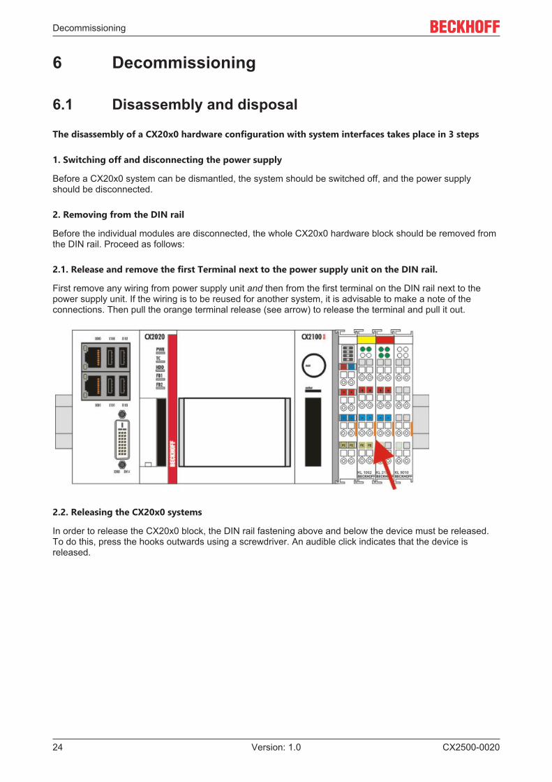
2.1. Release and remove the first Terminal next to the power supply unit on the DIN rail.
First remove any wiring from power supply unit and then from the first terminal on the DIN rail next to thepower supply unit. If the wiring is to be reused for another system, it is advisable to make a note of theconnections. Then pull the orange terminal release (see arrow) to release the terminal and pull it out.
2.2. Releasing the CX20x0 systems
In order to release the CX20x0 block, the DIN rail fastening above and below the device must be released.To do this, press the hooks outwards using a screwdriver. An audible click indicates that the device isreleased.
Decommissioning
CX2500-0020 25Version: 1.0
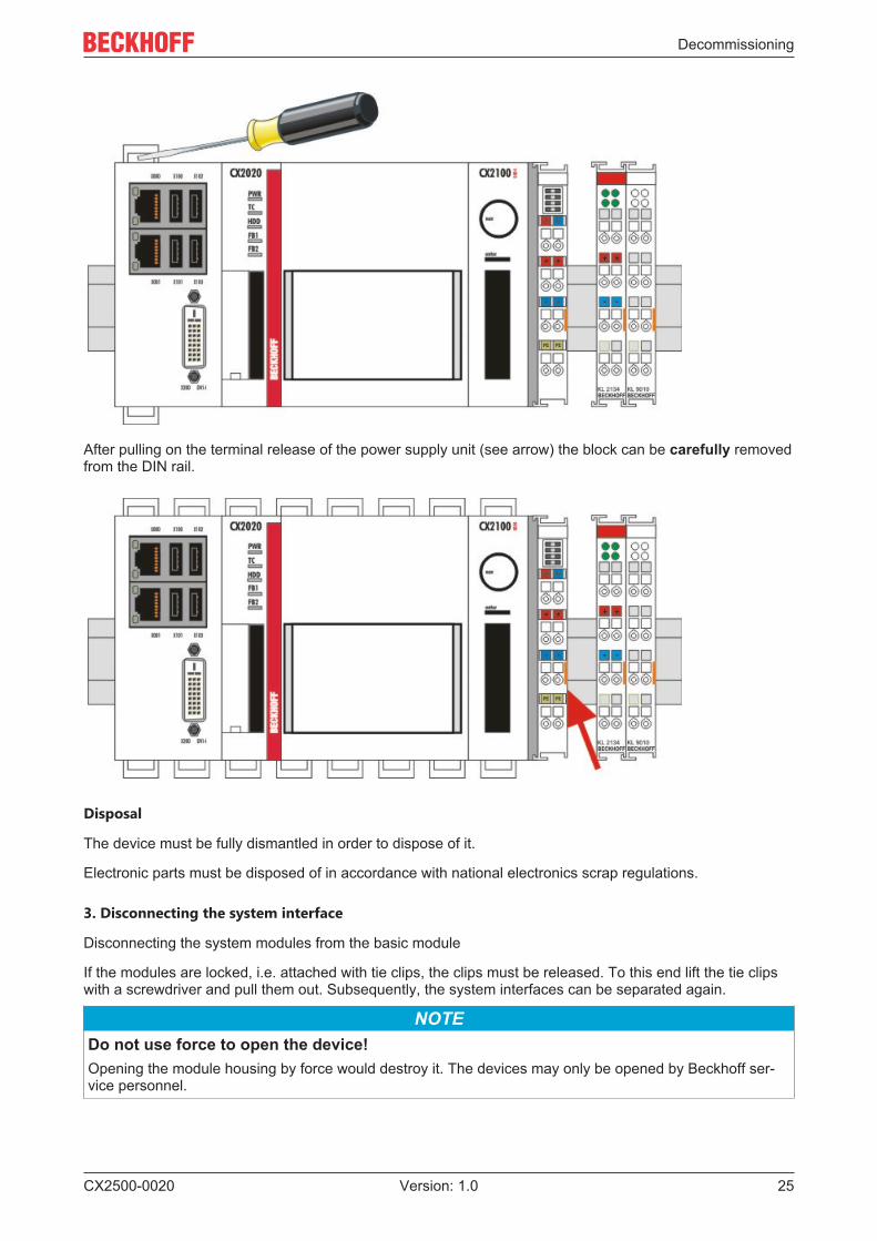
After pulling on the terminal release of the power supply unit (see arrow) the block can be carefully removedfrom the DIN rail.
Disposal
The device must be fully dismantled in order to dispose of it.
Electronic parts must be disposed of in accordance with national electronics scrap regulations.
3. Disconnecting the system interface
Disconnecting the system modules from the basic module
If the modules are locked, i.e. attached with tie clips, the clips must be released. To this end lift the tie clipswith a screwdriver and pull them out. Subsequently, the system interfaces can be separated again.
NOTEDo not use force to open the device!Opening the module housing by force would destroy it. The devices may only be opened by Beckhoff ser-vice personnel.
Appendix
CX2500-002026 Version: 1.0
7 Appendix
7.1 CertificationsAll products of the Embedded PC family are CE, UL and EAC certified. Since the product family iscontinuously developed further, we are unable to provide a full listing here. The current list of certifiedproducts can be found at www.beckhoff.com.
FCC Approvals for the United States of America
FCC: Federal Communications Commission Radio Frequency Interference Statement
This equipment has been tested and found to comply with the limits for a Class A digital device, pursuant toPart 15 of the FCC Rules. These limits are designed to provide reasonable protection against harmfulinterference when the equipment is operated in a commercial environment. This equipment generates, uses,and can radiate radio frequency energy and, if not installed and used in accordance with the instructionmanual, may cause harmful interference to radio communications. Operation of this equipment in aresidential area is likely to cause harmful interference in which case the user will be required to correct theinterference at his own expense.
FCC Approval for Canada
FCC: Canadian Notice
This equipment does not exceed the Class A limits for radiated emissions as described in the RadioInterference Regulations of the Canadian Department of Communications.
Appendix
CX2500-0020 27Version: 1.0
7.2 Support and ServiceBeckhoff and their partners around the world offer comprehensive support and service, making available fastand competent assistance with all questions related to Beckhoff products and system solutions.
Beckhoff's branch offices and representatives
Please contact your Beckhoff branch office or representative for local support and service on Beckhoffproducts!
The addresses of Beckhoff's branch offices and representatives round the world can be found on her internetpages:http://www.beckhoff.com
You will also find further documentation for Beckhoff components there.
Beckhoff Headquarters
Beckhoff Automation GmbH & Co. KG
Huelshorstweg 2033415 VerlGermany
Phone: +49(0)5246/963-0Fax: +49(0)5246/963-198e-mail: [email protected]
Beckhoff Support
Support offers you comprehensive technical assistance, helping you not only with the application ofindividual Beckhoff products, but also with other, wide-ranging services:
• support• design, programming and commissioning of complex automation systems• and extensive training program for Beckhoff system components
Hotline: +49(0)5246/963-157Fax: +49(0)5246/963-9157e-mail: [email protected]
Beckhoff Service
The Beckhoff Service Center supports you in all matters of after-sales service:
• on-site service• repair service• spare parts service• hotline service
Hotline: +49(0)5246/963-460Fax: +49(0)5246/963-479e-mail: [email protected]


Beckhoff Automation GmbH & Co. KGHülshorstweg 2033415 VerlGermanyPhone: +49 5246 [email protected]
More Information: www.beckhoff.com/CX2500-0020