Service Manual - Failure Analysis AXSM-0020 December 2015
50
Spicer ® Drive Axles Service Manual Failure Analysis AXSM-0020 December 2015
-
Upload
khangminh22 -
Category
Documents
-
view
0 -
download
0
Transcript of Service Manual - Failure Analysis AXSM-0020 December 2015
Spicer® Drive Axles
Service ManualFailure AnalysisAXSM-0020December 2015

AXSM-0020 December 2015 i
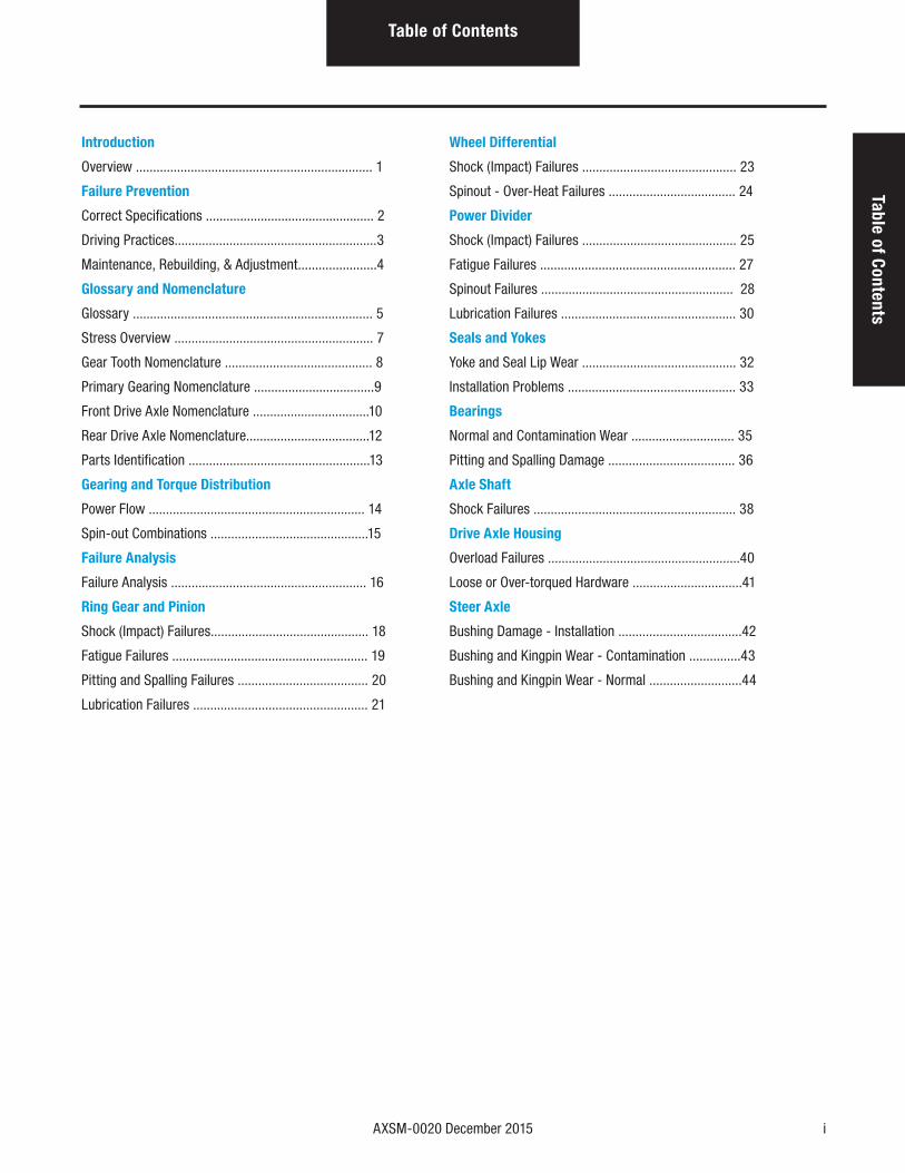
Table of ContentsTable of Contents
Introduction
Overview ..................................................................... 1
Failure Prevention
Correct Specifications ................................................. 2
Driving Practices...........................................................3
Maintenance, Rebuilding, & Adjustment.......................4
Glossary and Nomenclature
Glossary ...................................................................... 5
Stress Overview .......................................................... 7
Gear Tooth Nomenclature ........................................... 8
Primary Gearing Nomenclature ...................................9
Front Drive Axle Nomenclature ..................................10
Rear Drive Axle Nomenclature....................................12
Parts Identification .....................................................13
Gearing and Torque Distribution
Power Flow ............................................................... 14
Spin-out Combinations ..............................................15
Failure Analysis
Failure Analysis ......................................................... 16
Ring Gear and Pinion
Shock (Impact) Failures.............................................. 18
Fatigue Failures ......................................................... 19
Pitting and Spalling Failures ...................................... 20
Lubrication Failures ................................................... 21
Wheel Differential
Shock (Impact) Failures ............................................. 23
Spinout - Over-Heat Failures ..................................... 24
Power Divider
Shock (Impact) Failures ............................................. 25
Fatigue Failures ......................................................... 27
Spinout Failures ........................................................ 28
Lubrication Failures ................................................... 30
Seals and Yokes
Yoke and Seal Lip Wear ............................................. 32
Installation Problems ................................................. 33
Bearings
Normal and Contamination Wear .............................. 35
Pitting and Spalling Damage ..................................... 36
Axle Shaft
Shock Failures ........................................................... 38
Drive Axle Housing
Overload Failures ........................................................40
Loose or Over-torqued Hardware ................................41
Steer Axle
Bushing Damage - Installation ....................................42
Bushing and Kingpin Wear - Contamination ...............43
Bushing and Kingpin Wear - Normal ...........................44

AXSM-0020 December 2015 1
IntroductionIntroduction
Overview
This document is a general reference guide to mechanical failures of heavy truck axles. We approach the subject of axle failure from several perspectives ranging from basic principles of drive train operation to the evidence available from examining failed parts.
In preparing this guide, our objective was to help the skilled technician identify all the contributing causes of drive axle failures. With improved understanding of how and why an axle failed, the technician will not only be able to repair the carrier successfully, but also pinpoint any conditions that may need to be changed to prevent a repeat failure.
Here is an overview of the different sections of this guide:
• Failure Prevention - Explains how to prevent axle failures through proper procurement, operation, and maintenance.
• Glossary and Nomenclature - Covers the terminology of axle components including function, fatigue, and failure. This
section illustrates the primary forms of mechanical stress and also provides gearing and gear tooth nomenclature.
• Gearing and Torque Distribution - Reviews the principles of power flow through drive axles in various gear ranges and
equipment configurations. This section also illustrates different forms of spin-out, a major operating cause of axle failure.
• Failure Analysis - Explains how to diagnose the cause of a component failure. The main feature of this section is a photographic
review of actual failed parts matched with a description of the failure, the probable cause, and methods of prevention.
At Dana, we are interested in knowing your reaction to this guide and we welcome comments and contributions to future reference materials. Contact your Dana representative or contact us directly at www.dana.com.
2 AXSM-0020 December 2015
Failure Prevention
Correct Specifications
This section considers three general areas of truck procurement, operation and maintenance that will help prevent axle failure:
• Correct Specifications - matching the axle to the load and expected road conditions
• Drive Practices - training combined with proper use of installed equipment
• Maintenance, Rebuilding and Adjustment - with special emphasis on lubrication
Correctly spec’ing a drive axle for the vehicle and for the job to be done is an essential factor in preventing axle failures. It is extremely important to spec an axle of sufficient strength to work under the planned vehicle operational environment as well as the vehicle load rating.
Operating a vehicle outside of the specification (i.e., overloading and/or operating under more demanding conditions) may increase torque requirements and could cause premature damage or failure of axle components.
The drive axle must be designed with strength capable of withstanding the punishment of a loaded truck in operation. All components - gears, shafts, bearings, and housing - must meet three essential requirements:
• To carry the load. In most instances, the drive axle supports the major portion of the truck and its payload.
• To withstand the stress of torque developed by the engine and multiplied by the drive train.
• To withstand the stress of impact and shock forces created by road conditions and vehicle operation.
The capability of a drive axle to carry its share of the vehicle load is expressed as axle rated capacity Gross Axle Weight Rating (GAWK). To prevent axle overloading, the axle rating must be compatible with the weight specification of the vehicle, load, and expected operating conditions. Overloading will cause damage to the axle assembly parts.
See Spicer Drive Axle Application Guidelines (AXAG-0200).
Torque is Important
The primary function of a drive axle is to provide gear reduction which multiplies torque and transmits it to the driving wheels. In a truck power train, the engine develops horsepower and delivers the power in the form of torque. The transmission multiplies this torque and delivers it to the drive axle which multiplies torque a second time.
The drive axle gearing and its related components must be designed to transmit this torque to the driving wheels, so they will move the combined weight of the vehicle and load over expected road conditions.
Torque requirements vary with different grades and road conditions. Off-highway vehicles such as construction trucks must operate on rough or soft surface roads and steep grades. This requires greater torque for efficient operation. Vehicles with equivalent load ratings and operating at constant speeds on highways require less torque.
Vehicle Load Ratings
There are two different vehicle load ratings:
• Trucks are rated by Gross Vehicle Weight (GVW) which is the truck weight plus the weight of its load.
• Tractor-trailer rigs are rated by Gross Combination Weight (GCW) which is the weight of the tractor, trailer, and payload.
These ratings, as they relate to engine power and the torque required to move the weight, determine the required axle gearing strength.
Vehicle Operation
A vehicle is designed to do a certain job under certain conditions. More severe use of the vehicle such as overloading or operating under adverse road conditions not considered when spec'ing the axle is termed misuse or incorrect operation. Under severe misuse, the axle could fail immediately. With lesser misuse, the axle parts could progressively fail over a period of time. When unusual operating conditions are anticipated, get professional help in spec'ing a drive axle.
AXSM-0020 December 2015 3
Failure PreventionFailure Prevention
Driving Practices
Driving practices have a large influence on the service life of a truck axle. Good driving practices can eliminate shock and prevent undue strain not just on the axle, but on the entire truck.
There are two driver practices that are detrimental to axle parts life:
• Subjecting the vehicle to undue rough handling
• Driving under road conditions not specified
Either of these practices could cause premature axle failure.
Even conscientious drivers may encounter an unusual adverse situation of an exceptionally rough road. The driver should be trained to regulate speed and brake application according to road conditions.
Training is Essential
Driving a truck is an important job that can be performed more effectively with thorough training. The driver needs to know all the specifics about the hauling job such as payload characteristics, anticipated road conditions, and roads to be avoided. The driver must also be well informed about the equipment. For example, the driver should know answers to such questions as:
• What was the truck designed for?
• Why does the truck have a differential lockout?
• What is the function of a controlled traction differential?
• What are the benefits of 2-speed gearing in the drive axle?
A well-informed driver with proper training will eliminate many drive axle failures.
Failure-Preventing Equipment
Spicer tandem axles incorporate design features that can help prevent axle failures. Four important equipment features are:
• Inter-axle Differential Lockout
• Controlled Traction Differential
• 2-Speed (Dual Range) Gearing
• Drive Axle Wheel Differential Lock
The driver must know the purpose as well as the proper use of these important design features.
Inter-axle Differential Lockout
See Spicer Driver Instruction AXDR-0126.
The inter-axle differential lockout increases traction effort under adverse road conditions.
When engaged, the lockout provides positive drive to both axles. When the drive wheels of one axle are subjected to a condition of wheel spinning, the drive will continue to the other axle (to the wheels with traction) and move the truck.
Proper use of this lockout feature is important:
• Do not engage lockout while wheels are spinning.
• Do not engage lockout when driving conditions are good.
Improper use of the lockout could result in unnecessary axle parts failure.
Controlled Traction Differential
A controlled traction differential is a biasing unit designed into the axle wheel differential. It provides the truck with effective traction control under adverse driving conditions, especially off the highway. A controlled traction differential is especially effective in minimizing the possibility of spinout.
4 AXSM-0020 December 2015
Failure Prevention
2-Speed (Dual Range) Gearing
See Spicer Driver Instruction AXDR-0134.
Spicer drive axles are equipped with 2-speed gearing to provide maximum operating efficiencies in two extreme situations:
• Off-highway fully loaded
• On-highway fully loaded
The low range provides deep reduction and maximum torque when off-highway or on steep grades. The high range provides a faster ratio for cruising and fuel economy.
Premature failures of shifting parts, drive axles, and other drive train components can be prevented by proper driving per manual instructions and training. There are two important rules to follow:
• Do not abuse axle-shifting parts. Follow the instructions for shifting the axle.
• Do not abuse the drive train components. Use low range when torque requirements are high such as on rough roads, onsteep grades, and under other adverse conditions.
Drive Axle Wheel Differential Lock
See Spicer Drive Instruction AXDR-0130.
The drive axle wheel differential lock is an air-actuated clutch which positively locks the differential gearing in the rear axle. When this clutch is engaged, power flows to the tires without any differential action, giving each wheel all the torque the road conditions will permit.
A cab-mounted valve moves the wheel differential lock in or out of engagement. This motion also trips an electrical switch that activates a light in the cab or sounds an audible device to indicate that the wheel differential lock is engaged.
When the clutch is disengaged, the differential operates normally, dividing torque equally between the tires and compensating normally for cornering or tire size variations.
Maintenance, Rebuilding, & Adjustment
Proper maintenance is essential to achieve the maximum life designed and built into a drive axle. Perhaps the most important element of maintenance is proper lubrication. Incorrect or lack of lubrication is extremely detrimental to the life of drive axle parts.
Lubricant is the life-blood of the axle gears and bushings. It prevents metal-to-metal contact and keeps the parts clean and running cool. To get all the benefits of lubrication, you must:
• Use the proper lube.
• Maintain the proper lube level.
• Change lube at specified intervals.
• Periodically clean magnetic plugs.
• Clean the magnetic drain plug to remove metallic dust or fine particles.
• Keep filters and strainers clean and filled after an initial break-in of 5,000 miles. When filled with a Spicer approved synthetic lubricant at the factory, the 5,000 mile drain is not required.
To assure correct lubrication and long life for your Spicer drive axle, follow instructions in the Spicer Service Manuals. For additional lubrication information, see TCMT-0021.
Rebuilding and Adjusting
Proper reassembles and replacement of all damaged or defective parts is extremely important in achieving good life from an axle overhaul. Cleaning and close inspection of parts is vital.
To achieve maximum value from a rebuild, replace lower cost items such as thrust washers, seals, and bushings as well as worn and damaged major parts.
Follow instructions for correctly adjusting bearing preloads, shaft endplay, and gear and pinion tooth contact patterns.
All these procedures will help extend the life of your rebuilt axle. Refer to Spicer Axle Service and Maintenance Literature for detailed information.
AXSM-0020 December 2015 5
Glossary & N
omenclature
Glossary & Nomenclature
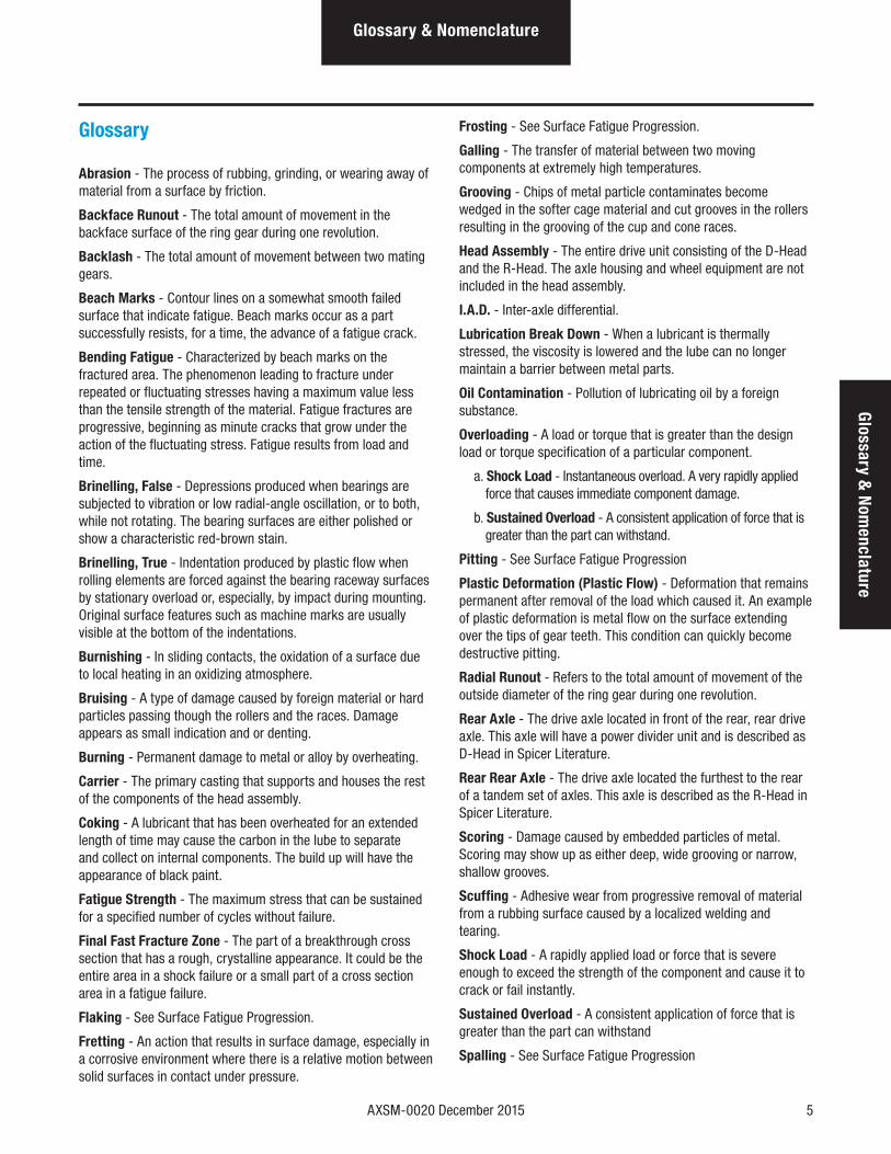
Glossary
Abrasion - The process of rubbing, grinding, or wearing away of material from a surface by friction.
Backface Runout - The total amount of movement in the backface surface of the ring gear during one revolution.
Backlash - The total amount of movement between two mating gears.
Beach Marks - Contour lines on a somewhat smooth failed surface that indicate fatigue. Beach marks occur as a part successfully resists, for a time, the advance of a fatigue crack.
Bending Fatigue - Characterized by beach marks on the fractured area. The phenomenon leading to fracture under repeated or fluctuating stresses having a maximum value less than the tensile strength of the material. Fatigue fractures are progressive, beginning as minute cracks that grow under the action of the fluctuating stress. Fatigue results from load and time.
Brinelling, False - Depressions produced when bearings are subjected to vibration or low radial-angle oscillation, or to both, while not rotating. The bearing surfaces are either polished or show a characteristic red-brown stain.
Brinelling, True - Indentation produced by plastic flow when rolling elements are forced against the bearing raceway surfaces by stationary overload or, especially, by impact during mounting. Original surface features such as machine marks are usually visible at the bottom of the indentations.
Burnishing - In sliding contacts, the oxidation of a surface due to local heating in an oxidizing atmosphere.
Bruising - A type of damage caused by foreign material or hard particles passing though the rollers and the races. Damage appears as small indication and or denting.
Burning - Permanent damage to metal or alloy by overheating.
Carrier - The primary casting that supports and houses the rest of the components of the head assembly.
Coking - A lubricant that has been overheated for an extended length of time may cause the carbon in the lube to separate and collect on internal components. The build up will have the appearance of black paint.
Fatigue Strength - The maximum stress that can be sustained for a specified number of cycles without failure.
Final Fast Fracture Zone - The part of a breakthrough cross section that has a rough, crystalline appearance. It could be the entire area in a shock failure or a small part of a cross section area in a fatigue failure.
Flaking - See Surface Fatigue Progression.
Fretting - An action that results in surface damage, especially in a corrosive environment where there is a relative motion between solid surfaces in contact under pressure.
Frosting - See Surface Fatigue Progression.
Galling - The transfer of material between two moving components at extremely high temperatures.
Grooving - Chips of metal particle contaminates become wedged in the softer cage material and cut grooves in the rollers resulting in the grooving of the cup and cone races.
Head Assembly - The entire drive unit consisting of the D-Head and the R-Head. The axle housing and wheel equipment are not included in the head assembly.
I.A.D. - Inter-axle differential.
Lubrication Break Down - When a lubricant is thermally stressed, the viscosity is lowered and the lube can no longer maintain a barrier between metal parts.
Oil Contamination - Pollution of lubricating oil by a foreign substance.
Overloading - A load or torque that is greater than the design load or torque specification of a particular component.
a. Shock Load - Instantaneous overload. A very rapidly applied force that causes immediate component damage.
b. Sustained Overload - A consistent application of force that is greater than the part can withstand.
Pitting - See Surface Fatigue Progression
Plastic Deformation (Plastic Flow) - Deformation that remains permanent after removal of the load which caused it. An example of plastic deformation is metal flow on the surface extending over the tips of gear teeth. This condition can quickly become destructive pitting.
Radial Runout - Refers to the total amount of movement of the outside diameter of the ring gear during one revolution.
Rear Axle - The drive axle located in front of the rear, rear drive axle. This axle will have a power divider unit and is described as D-Head in Spicer Literature.
Rear Rear Axle - The drive axle located the furthest to the rear of a tandem set of axles. This axle is described as the R-Head in Spicer Literature.
Scoring - Damage caused by embedded particles of metal. Scoring may show up as either deep, wide grooving or narrow, shallow grooves.
Scuffing - Adhesive wear from progressive removal of material from a rubbing surface caused by a localized welding and tearing.
Shock Load - A rapidly applied load or force that is severe enough to exceed the strength of the component and cause it to crack or fail instantly.
Sustained Overload - A consistent application of force that is greater than the part can withstand
Spalling - See Surface Fatigue Progression
6 AXSM-0020 December 2015
Glossary & Nomenclature
Stress - Force per unit of area, often defined as force acting through an area within a plane.
Stress Risers - Changes in contour or discontinuities in structure that cause local increases in stress.
Surface Fatigue Progression - There are four stages of fatigue
for the surface of a metal part under operating stress:
• Frosting - Superficial material displacement on gear teeth that present a non-destructive burnished appearance.
• Pitting - This surface fatigue condition occurs when the endurance limits of the material are exceeded.
• Initial - This is the mildest stage of pitting. It consists of definite pits from a pin hole size to .030" in diameter. Initial pitting continues until the tooth is able to carry the load without further distress.
• Moderate- In this stage, the pits are approximately double in size of the initial pitting. The gear teeth have not been weakened and there is no danger of breakage.
• Destructive - At this stage the pits are considerably larger and deeper than those with moderate pitting. Gears found in this stage should be replaced.
• Flaking - An advanced type of pitting resulting from contact fatigue. Material falls away from the surface in the form of shallow flakes or scale-like particles.
• Spalling - Deterioration of a highly stressed surface by surface fatigue producing irregularly shaped, sharp-edged, deep cavities. Spalling is a severe form of flaking.
Torsion - A twisting action resulting in shear stresses and strains.
AXSM-0020 December 2015 7
Glossary & N
omenclature
Glossary & Nomenclature
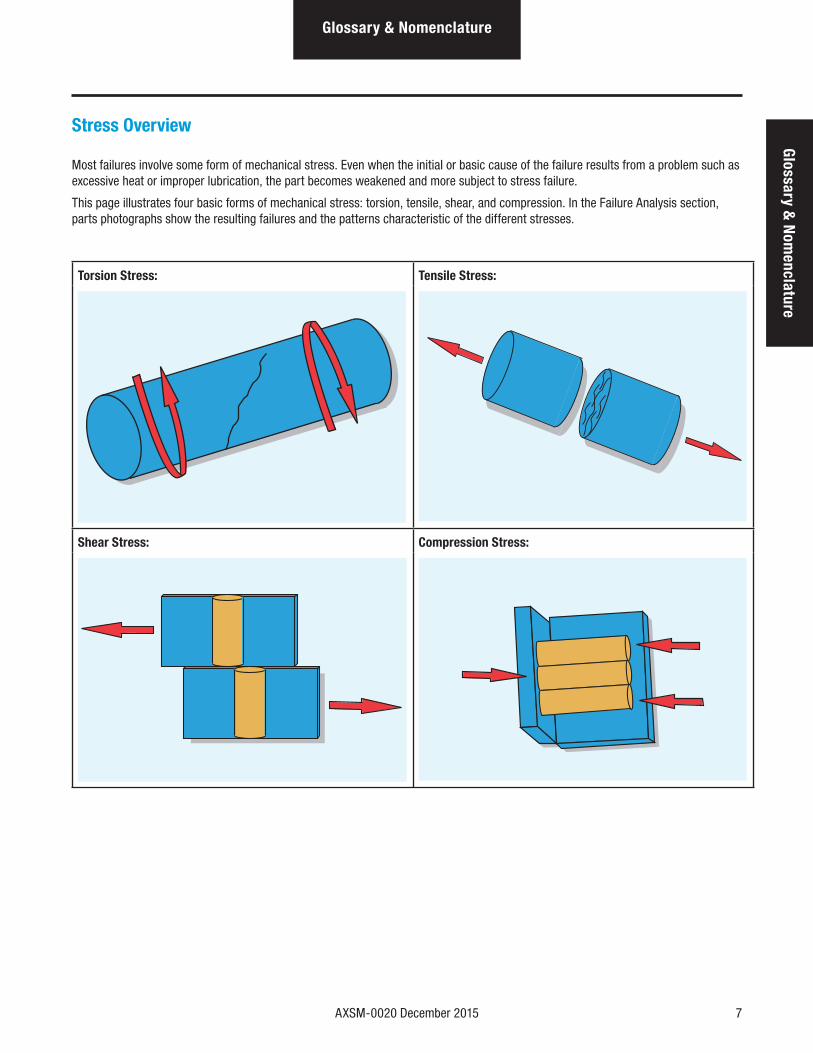
Stress Overview
Most failures involve some form of mechanical stress. Even when the initial or basic cause of the failure results from a problem such as excessive heat or improper lubrication, the part becomes weakened and more subject to stress failure.
This page illustrates four basic forms of mechanical stress: torsion, tensile, shear, and compression. In the Failure Analysis section, parts photographs show the resulting failures and the patterns characteristic of the different stresses.
Torsion Stress: Tensile Stress:
Shear Stress: Compression Stress:
8 AXSM-0020 December 2015
Glossary & Nomenclature
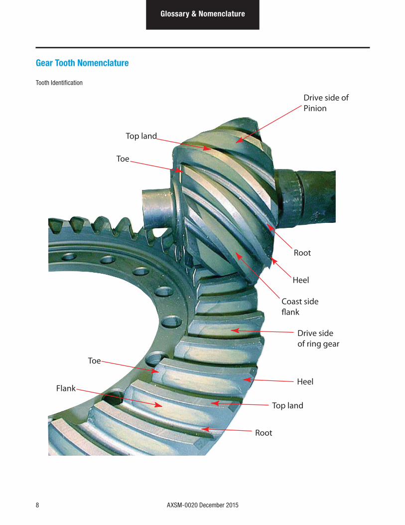
Gear Tooth Nomenclature
Tooth Identification
Drive side ofPinion
Top land
Toe
Root
Heel
Coast sideflank
Drive sideof ring gear
Heel
Top land
Root
Toe
Flank

AXSM-0020 December 2015 9
Glossary & N
omenclature
Glossary & Nomenclature
Primary Gearing Nomenclature
Ring and Pinion Identification - To aid in identifying gear sets, both parts are stamped with information such as number of pinion and ring gear teeth, individual part numbers, and match set numbers.
Reminder: The ring and pinion are a matched set and must be replaced together.
Manufacturingnumbers
Part numberMatch setnumber
Date codeNumber of gear teeth
Date code
Part number
Match setnumber
Manufacturingnumbers
Number of pinion teeth
2697F 11129723 37-T K K 3 G 17
8L
1274
45 10-37 GS1G
17
8L
2697F11
10 AXSM-0020 December 2015
Glossary & Nomenclature
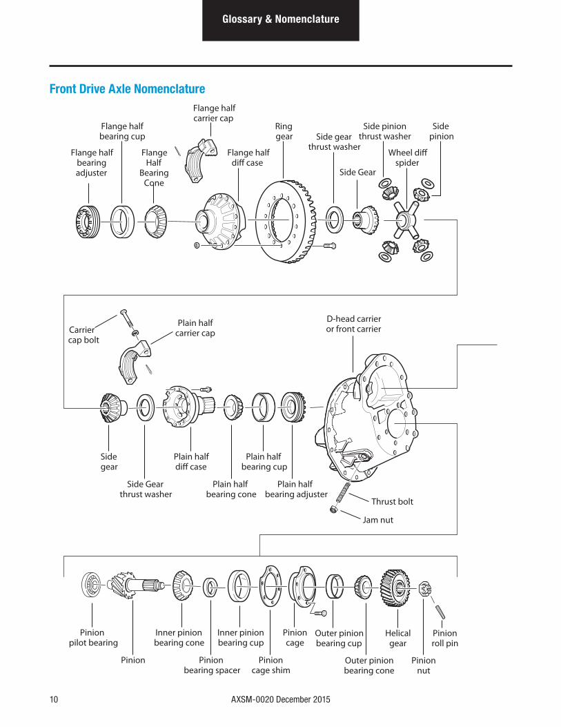
Front Drive Axle Nomenclature
Wheel diffspider
Side Gear
Side gearthrust washer
Flange halfdiff case
Ringgear
Side pinionthrust washer
FlangeHalf
BearingCone
Flange halfbearingadjuster
Flange halfbearing cup
Plain halfcarrier capCarrier
cap bolt
Sidepinion
D-head carrieror front carrier
Sidegear
Side Gearthrust washer
Plain halfdiff case
Plain halfbearing cone
Pinionpilot bearing
Inner pinionbearing cone
Inner pinionbearing cup
Pinioncage
Outer pinionbearing cone
Pinionnut
Pinion Pinionbearing spacer
Pinioncage shim
Outer pinionbearing cup
Helicalgear
Pinionroll pin
Plain halfbearing cup
Thrust bolt
Plain halfbearing adjuster
Flange halfcarrier cap
Jam nut
AXSM-0020 December 2015 11
Glossary & NomenclatureGlossary &
Nom
enclature
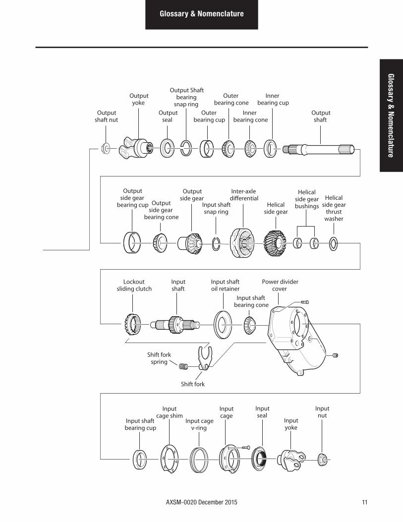
Lockoutsliding clutch
Inputshaft
Outputside gear
bearing cup
Outputside gear
Outputside gear
bearing cone
Helicalside gearbushings
Helicalside gear
thrustwasher
Input shaftsnap ring
Inputcage shim
Inputcage
Inputyoke
Input cagev-ring
Inputseal
Inputnut
Input shaftbearing cup
Inter-axledifferential
Innerbearing cone
Outputshaft
Outputshaft nut
Outputseal
Outerbearing cup
Outputyoke
Output Shaftbearing
snap ringOuter
bearing coneInner
bearing cup
Helicalside gear
Input shaftoil retainer
Input shaftbearing cone
Power dividercover
Shift fork
Shift forkspring
12 AXSM-0020 December 2015
Glossary & Nomenclature
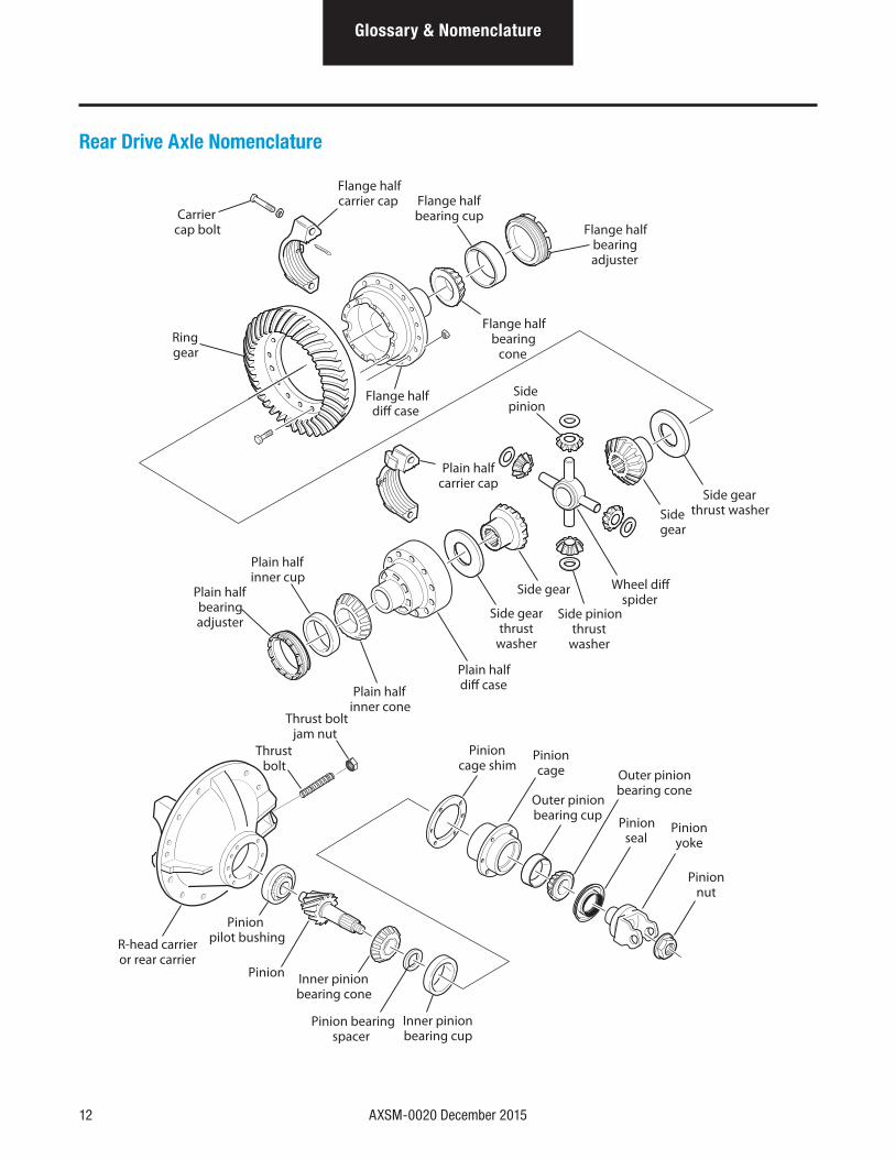
Rear Drive Axle Nomenclature
R-head carrieror rear carrier
Inner pinionbearing cone
Pinioncage shim
Inner pinionbearing cup
Pinion bearingspacer
Pinionpilot bushing
Pinion
Pinioncage
Outer pinionbearing cup
Outer pinionbearing cone
Pinionseal
Pinionyoke
Pinionnut
Thrust bolt
Thrust boltjam nut
Side gearthrust washer
Carriercap bolt
Side gear
Sidegear
Plain halfdiff case
Wheel diffspider
Side pinionthrust
washer
Plain halfinner cone
Plain halfinner cup
Sidepinion
Plain halfcarrier cap
Plain halfbearingadjuster
Side gearthrust
washer
Flange halfbearingadjuster
Flange halfbearing
cone
Flange halfbearing cup
Flange halfdiff case
Ringgear
Flange halfcarrier cap
AXSM-0020 December 2015 13
Glossary & N
omenclature
Glossary & Nomenclature
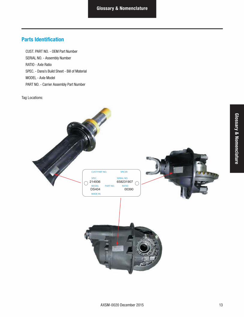
Parts Identification
CUST. PART NO. - OEM Part Number
SERIAL NO. - Assembly Number
RATIO - Axle Ratio
SPEC. - Dana’s Build Sheet - Bill of Material
MODEL - Axle Model
PART NO. - Carrier Assembly Part Number
Tag Locations:
CUST PART NO. SPICER
SPEC. SERIAL NO.
MODEL PART NO. RATIO
MADE IN:
14 AXSM-0020 December 2015
Gearing & Torque Distribution
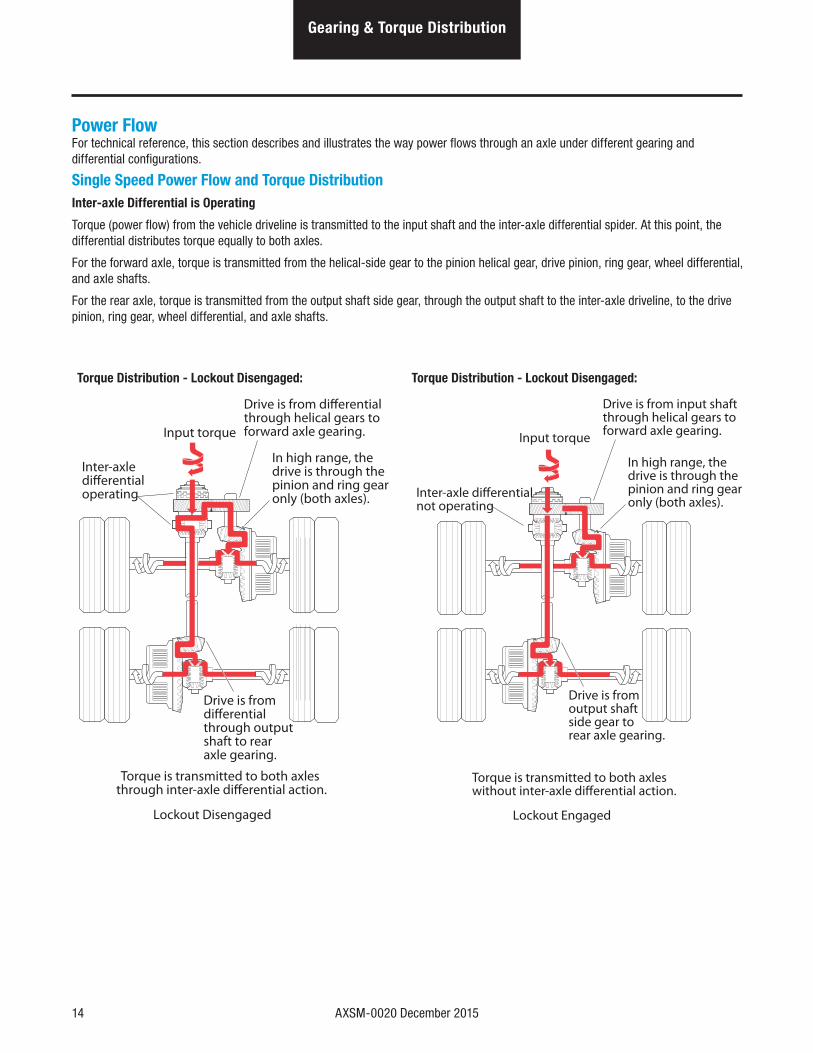
Power FlowFor technical reference, this section describes and illustrates the way power flows through an axle under different gearing and differential configurations.
Single Speed Power Flow and Torque DistributionInter-axle Differential is Operating
Torque (power flow) from the vehicle driveline is transmitted to the input shaft and the inter-axle differential spider. At this point, the differential distributes torque equally to both axles.
For the forward axle, torque is transmitted from the helical-side gear to the pinion helical gear, drive pinion, ring gear, wheel differential, and axle shafts.
For the rear axle, torque is transmitted from the output shaft side gear, through the output shaft to the inter-axle driveline, to the drive pinion, ring gear, wheel differential, and axle shafts.
Torque Distribution - Lockout Disengaged: Torque Distribution - Lockout Disengaged:
Input torque
Inter-axle differential operating
Drive is from differential through helical gears to forward axle gearing.
Drive is from differential through output shaft to rear axle gearing.
Torque is transmitted to both axles through inter-axle differential action.
In high range, the drive is through the pinion and ring gear only (both axles).
Lockout Disengaged
Input torque
Inter-axle differential not operating
Drive is from input shaft through helical gears to forward axle gearing.
Drive is from output shaft side gear torear axle gearing.
Torque is transmitted to both axles without inter-axle differential action.
In high range, the drive is through the pinion and ring gear only (both axles).
Lockout Engaged
AXSM-0020 December 2015 15
Gearing & Torque Distribution
Gearing & Torque Distribution
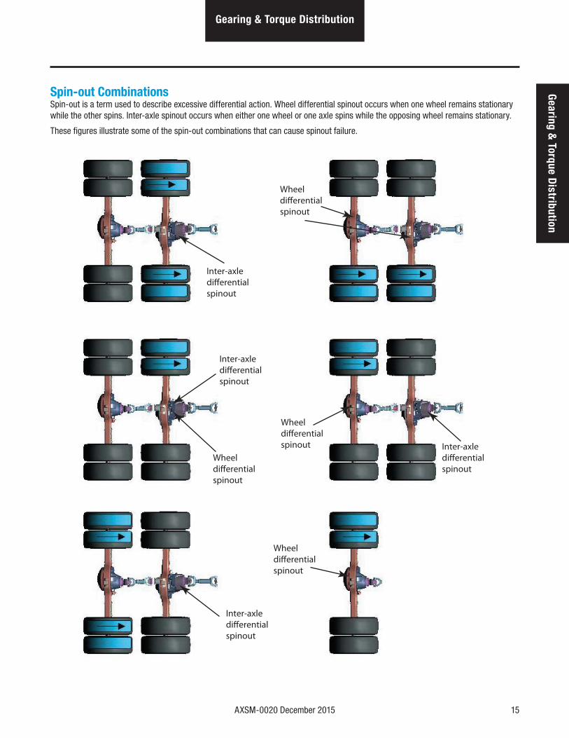
Spin-out CombinationsSpin-out is a term used to describe excessive differential action. Wheel differential spinout occurs when one wheel remains stationary while the other spins. Inter-axle spinout occurs when either one wheel or one axle spins while the opposing wheel remains stationary.
These figures illustrate some of the spin-out combinations that can cause spinout failure.
Inter-axledifferentialspinout
Wheeldifferentialspinout
Inter-axledifferentialspinout
Wheel differentialspinout
Wheeldifferentialspinout Inter-axle
differentialspinout
Inter-axledifferentialspinout
Wheeldifferentialspinout
16 AXSM-0020 December 2015
Failure Analysis
Failure Analysis
How to Diagnose a FailureFailure analysis is the process of determining the original cause of a component failure in order to keep it from happening again. Too often, when a failed component is replaced without determining its cause, there will be a recurring failure. If a carrier housing is opened, revealing a ring gear with a broken tooth, it is not enough to settle on the broken tooth as the cause of the carrier failure. Other parts of the carrier must be examined. For a thorough understanding of the failure and possible insight into related problems, the technician needs to observe the overall condition of the vehicle.
No one benefits when a failed component goes on the junk pile with the cause unknown. Nothing is more disturbing to a customer than a repeat failure. Systematically analyzing a failure to prevent a repeat occurrence assures quality service by avoiding unnecessary downtime and further expense to the customer.
The true cause of a failure can be better determined by knowing what to look for, determining how a piece of the equipment was running, and learning about previous problems. In some cases, the part itself is at fault. In the case of a rebuilt rear axle, mismatched gears may have been installed.
The more successful shops prevent repeat equipment failures by developing good failure analysis practices. Knowing how to diagnose the cause of a premature failure is one of the prerequisites of a good heavy-equipment technician.
The following five steps are an effective approach to good failure diagnostics:
1. Document the problem.
2. Make a preliminary investigation.
3. Prepare the parts for inspection.
4. Find the cause of the failure.
5. Correct the cause of the problem.
Document the ProblemHere are some guidelines for starting to learn about a failure, including questions to ask:
• Talk to the operator of the truck.
• Look at the service records.
• Find out when the truck was last serviced.
• Ask: In what type of service is the truck being used?
• Ask: Has this particular failure occurred before?
• Ask: How was the truck working prior to the failure?
You need to be a good listener. Sometimes, insignificant or unrelated symptoms can point to the cause of the failure.
• Ask: Was the vehicle operating at normal temperatures?
• Ask: Were the gauges showing normal ranges of operation?
• Ask: Was there any unusual noise or vibration?
After listening, review the previous repair and maintenance records. If there is more than one driver, talk to all of them and compare their observations for consistency with the service and maintenance records. Verify the chassis Vehicle Identification Number (VIN) number from the vehicle identification plate, as well as the mileage and hours on the vehicle.
AXSM-0020 December 2015 17
Failure AnalysisFailure Analysis
Make a Preliminary InvestigationThese steps consist of external inspections and observations that will be valuable when combined with the results of the parts examination.
• Look for leaks, cracks or other damage that can point to the cause of the failure.
• Make note of obvious leaks around plugs and seals. A missing fill or drain plug would be an obvious cause for concern.
• Look for cracks in the carrier housing (harder to see, but sometimes visible).
• Does the general mechanical condition of the vehicle indicate proper maintenance or are there signs of neglect?
• Are the tires in good condition and do the sizes match?
• If equipped with a torque-limiting device, is it working properly?
During the preliminary investigation, write down anything out of the ordinary for later reference. Items that appear insignificant now may take on more importance when the subassemblies are torn down.
Prepare the Parts for InspectionAfter the preliminary investigation, locate the failure and prepare the part for examination. In carrier failure analysis, it may be necessary to disassemble the unit.
• When disassembling subassemblies and parts, do not clean the parts immediately since cleaning may destroy some of the evidence.
• When tearing down the rear axle, do it in the recommended manner. Minimize any further damage to the unit.
• Ask more questions when examining the interior of the carrier. Does the lubricant meet the manufacturer specifications regarding quality, quantity, and viscosity? As soon as you have located the failed part, take time to analyze the data.
Find the Cause of the FailureHere begins the real challenge to determine the exact cause of the failure. Keep in mind that there is no benefit to replacing a failed part without determining the cause of the failure. For example, after examining a failed part and finding that the failure is caused by a lack of lubrication, you must determine if there was an external leak. Obviously, if there is an external leak, just replacing the failed gear is not going to correct the situation.
Another important consideration is to determine the specific type of failure which can be a valuable indicator for the cause of failure.The following pages show different types of failures and possible causes. Use this as a guide in determining types of failures and in correcting problems.
Correct the Cause of the ProblemOnce the cause of the problem has been determined, refer to the appropriate Service Manual to perform the repairs.
18 AXSM-0020 December 2015
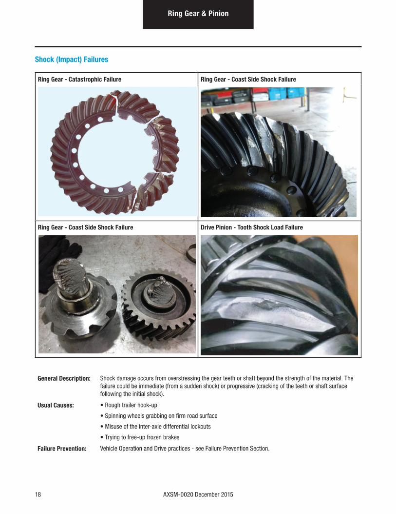
Shock (Impact) Failures
Ring Gear - Catastrophic Failure Ring Gear - Coast Side Shock Failure
Ring Gear - Coast Side Shock Failure Drive Pinion - Tooth Shock Load Failure
General Description: Shock damage occurs from overstressing the gear teeth or shaft beyond the strength of the material. The failure could be immediate (from a sudden shock) or progressive (cracking of the teeth or shaft surface following the initial shock).
Usual Causes: • Rough trailer hook-up
• Spinning wheels grabbing on firm road surface
• Misuse of the inter-axle differential lockouts
• Trying to free-up frozen brakes
Failure Prevention: Vehicle Operation and Drive practices - see Failure Prevention Section.
Ring Gear & Pinion
AXSM-0020 December 2015 19
Ring Gear & PinionRing Gear &
Pinion
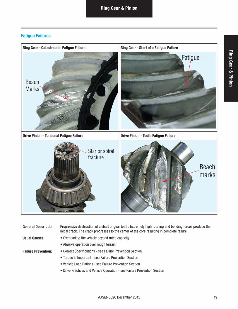
Fatigue Failures
Ring Gear - Catastrophic Fatigue Failure Ring Gear - Start of a Fatigue Failure
Drive Pinion - Torsional Fatigue Failure Drive Pinion - Tooth Fatigue Failure
General Description: Progressive destruction of a shaft or gear teeth. Extremely high rotating and bending forces produce the initial crack. The crack progresses to the center of the core resulting in complete failure.
Usual Causes: • Overloading the vehicle beyond rated capacity
• Abusive operation over rough terrain
Failure Prevention: • Correct Specifications - see Failure Prevention Section
• Torque is Important - see Failure Prevention Section
• Vehicle Load Ratings - see Failure Prevention Section
• Drive Practices and Vehicle Operation - see Failure Prevention Section
20 AXSM-0020 December 2015
Ring Gear & Pinion
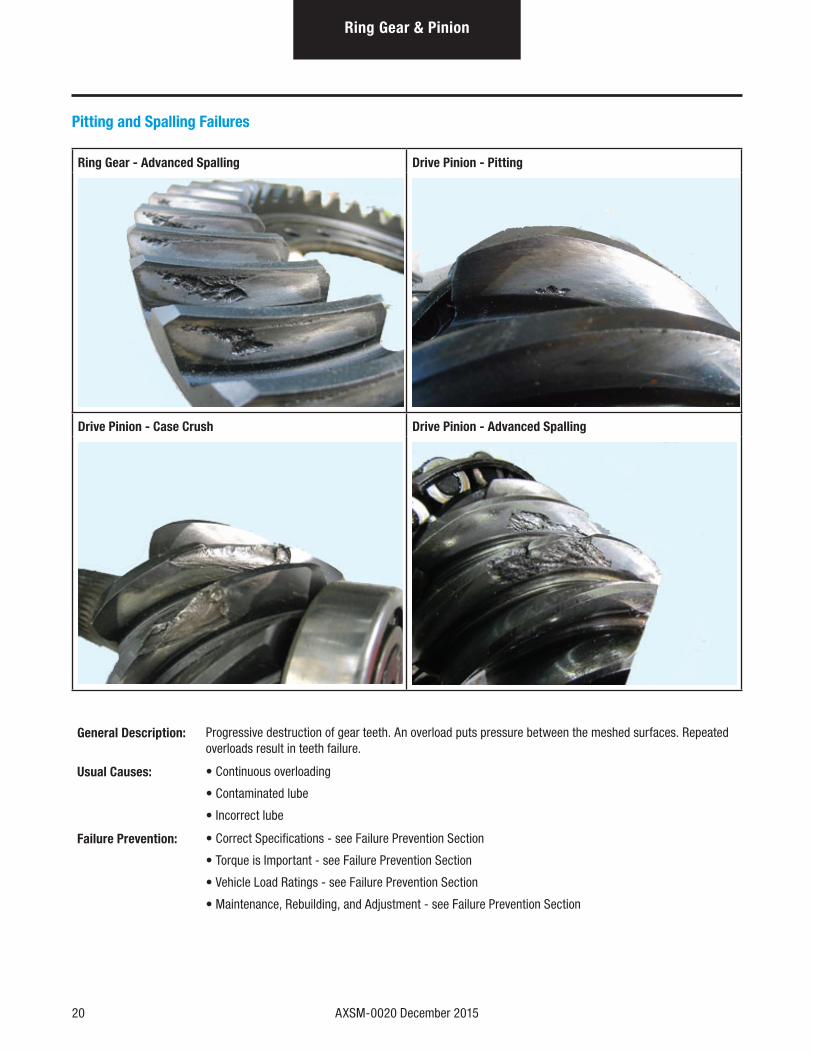
Pitting and Spalling Failures
Ring Gear - Advanced Spalling Drive Pinion - Pitting
Drive Pinion - Case Crush Drive Pinion - Advanced Spalling
General Description: Progressive destruction of gear teeth. An overload puts pressure between the meshed surfaces. Repeated overloads result in teeth failure.
Usual Causes: • Continuous overloading
• Contaminated lube
• Incorrect lube
Failure Prevention: • Correct Specifications - see Failure Prevention Section
• Torque is Important - see Failure Prevention Section
• Vehicle Load Ratings - see Failure Prevention Section
• Maintenance, Rebuilding, and Adjustment - see Failure Prevention Section
AXSM-0020 December 2015 21
Ring Gear & Pinion
Ring Gear & Pinion
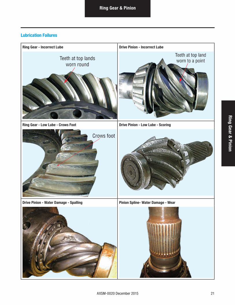
Lubrication Failures
Ring Gear - Incorrect Lube Drive Pinion - Incorrect Lube
Ring Gear - Low Lube - Crows Foot Drive Pinion - Low Lube - Scoring
Drive Pinion - Water Damage - Spalling Pinion Spline- Water Damage - Wear
22 AXSM-0020 December 2015
Ring Gear & Pinion
Lubrication Failures (cont'd)
General Description: Progressive destruction of components due to incorrect lube type, viscosity, or water damage resulting in complete failure.
Usual Causes: • Incorrect lube (wrong viscosity or wrong lube type): Will reduce the life of bearings, gears, bushings, and thrust washers.
• Containment Lube: Water, foreign material, and normal wear or break-in material can cause etching, scoring, or pitting to the contact surfaces. Foreign material in the lube is abrasive.
• Low or no lube: Will create friction which causes overheating, break-down of the protective film, and finally parts seizure of the surfaces of mating parts.
Failure Prevention: Maintenance, Rebuilding, and Adjustment - see Failure Prevention Section
AXSM-0020 December 2015 23
Wheel Differential
Wheel Differential
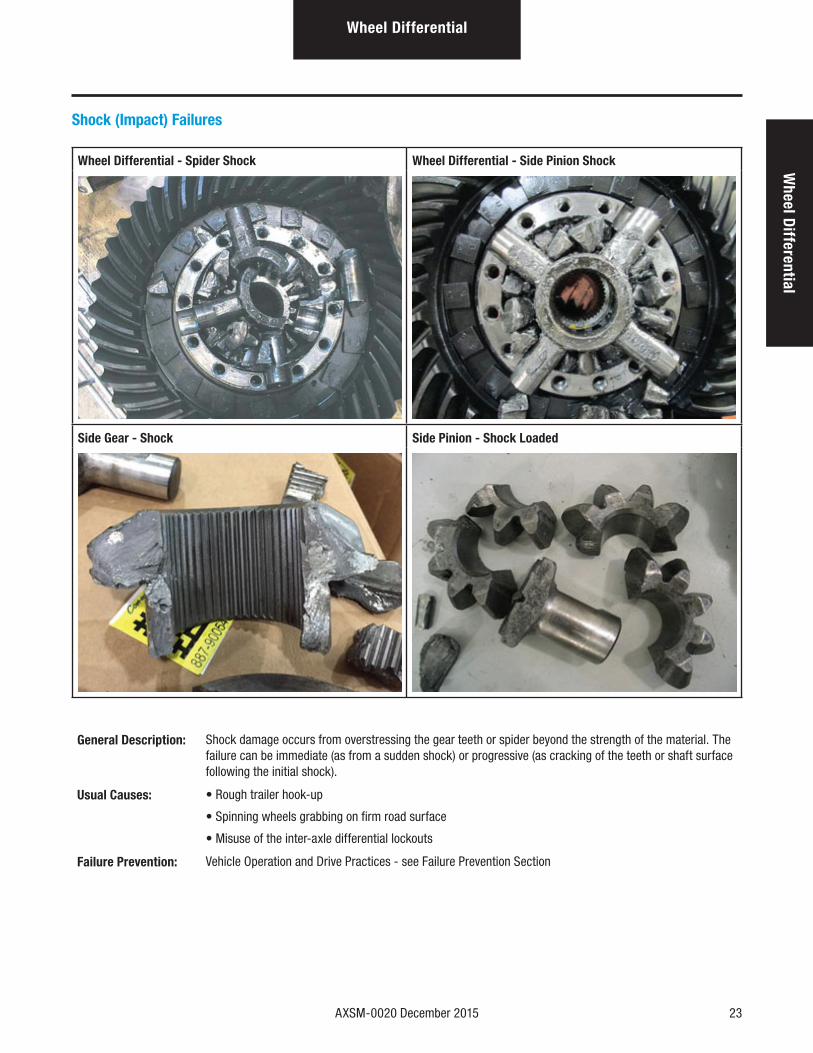
Shock (Impact) Failures
Wheel Differential - Spider Shock Wheel Differential - Side Pinion Shock
Side Gear - Shock Side Pinion - Shock Loaded
General Description: Shock damage occurs from overstressing the gear teeth or spider beyond the strength of the material. The failure can be immediate (as from a sudden shock) or progressive (as cracking of the teeth or shaft surface following the initial shock).
Usual Causes: • Rough trailer hook-up
• Spinning wheels grabbing on firm road surface
• Misuse of the inter-axle differential lockouts
Failure Prevention: Vehicle Operation and Drive Practices - see Failure Prevention Section
24 AXSM-0020 December 2015
Wheel Differential
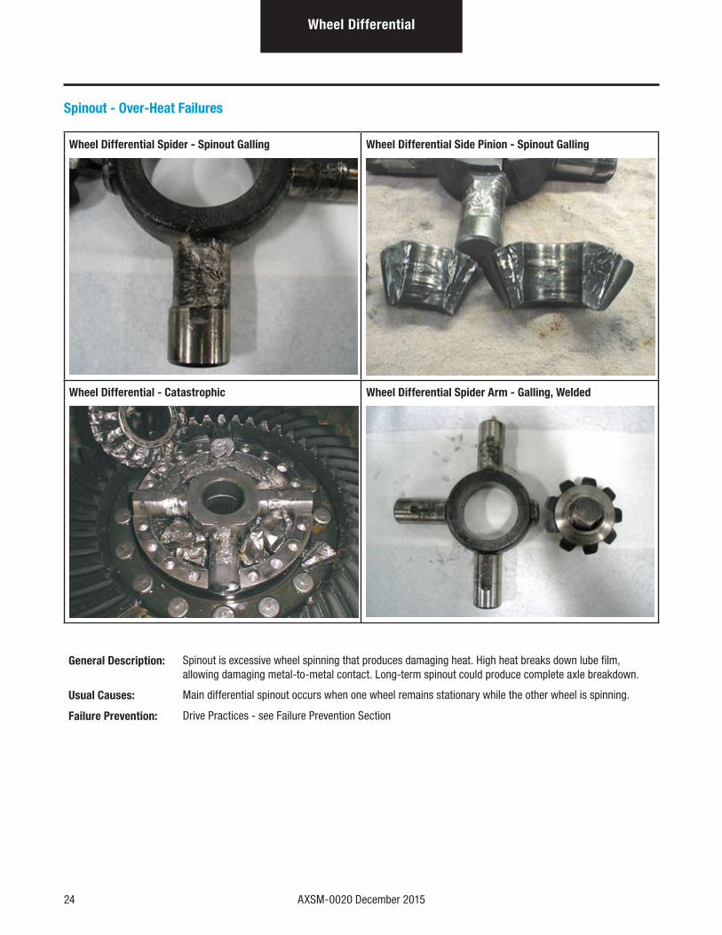
Spinout - Over-Heat Failures
Wheel Differential Spider - Spinout Galling Wheel Differential Side Pinion - Spinout Galling
Wheel Differential - Catastrophic Wheel Differential Spider Arm - Galling, Welded
General Description: Spinout is excessive wheel spinning that produces damaging heat. High heat breaks down lube film, allowing damaging metal-to-metal contact. Long-term spinout could produce complete axle breakdown.
Usual Causes: Main differential spinout occurs when one wheel remains stationary while the other wheel is spinning.
Failure Prevention: Drive Practices - see Failure Prevention Section
AXSM-0020 December 2015 25
Power D
ividerPower Divider
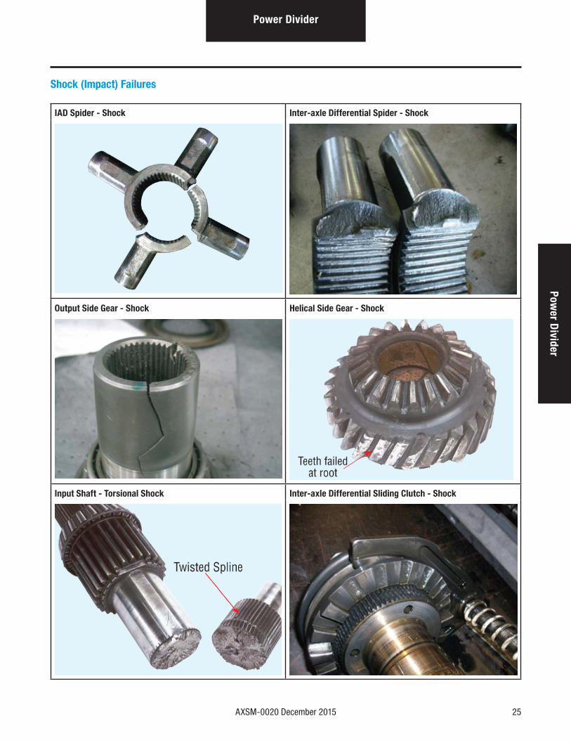
Shock (Impact) Failures
IAD Spider - Shock Inter-axle Differential Spider - Shock
Output Side Gear - Shock Helical Side Gear - Shock
Input Shaft - Torsional Shock Inter-axle Differential Sliding Clutch - Shock
26 AXSM-0020 December 2015
Power Divider
Shock (Impact) Failures (cont'd)
General Description: Shock damage occurs from overstressing the gear teeth or shaft beyond the strength of the material. The failure can be immediate (as from a sudden shock) or progressive (as cracking of the teeth or shaft surface following the initial shock).
Usual Causes: • Rough trailer hook-up
• Rough trailer hook-up
• Spinning wheels grabbing on firm road surface
• Misuse of the inter-axle differential lockouts
• Side stepping the clutch
Failure Prevention: Vehicle Operation and Drive Practices - see Failure Prevention Section
AXSM-0020 December 2015 27
Power D
ividerPower Divider
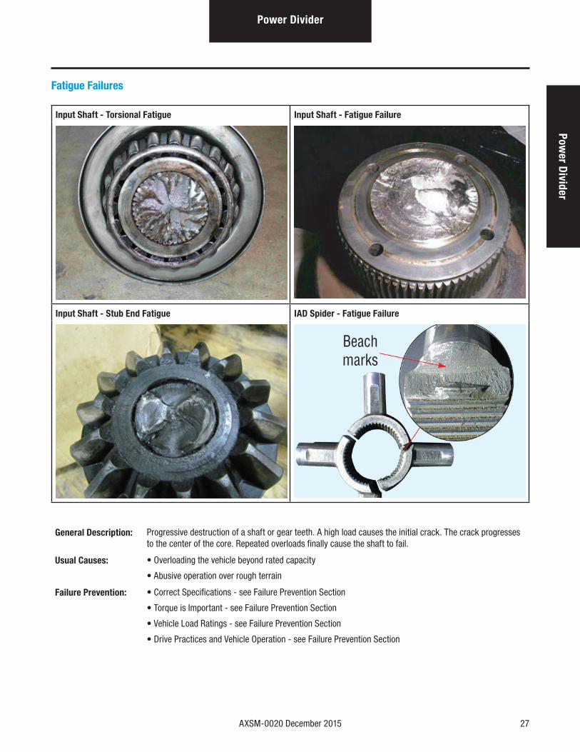
Fatigue Failures
Input Shaft - Torsional Fatigue Input Shaft - Fatigue Failure
Input Shaft - Stub End Fatigue IAD Spider - Fatigue Failure
General Description: Progressive destruction of a shaft or gear teeth. A high load causes the initial crack. The crack progresses to the center of the core. Repeated overloads finally cause the shaft to fail.
Usual Causes: • Overloading the vehicle beyond rated capacity
• Abusive operation over rough terrain
Failure Prevention: • Correct Specifications - see Failure Prevention Section
• Torque is Important - see Failure Prevention Section
• Vehicle Load Ratings - see Failure Prevention Section
• Drive Practices and Vehicle Operation - see Failure Prevention Section
28 AXSM-0020 December 2015
Power Divider
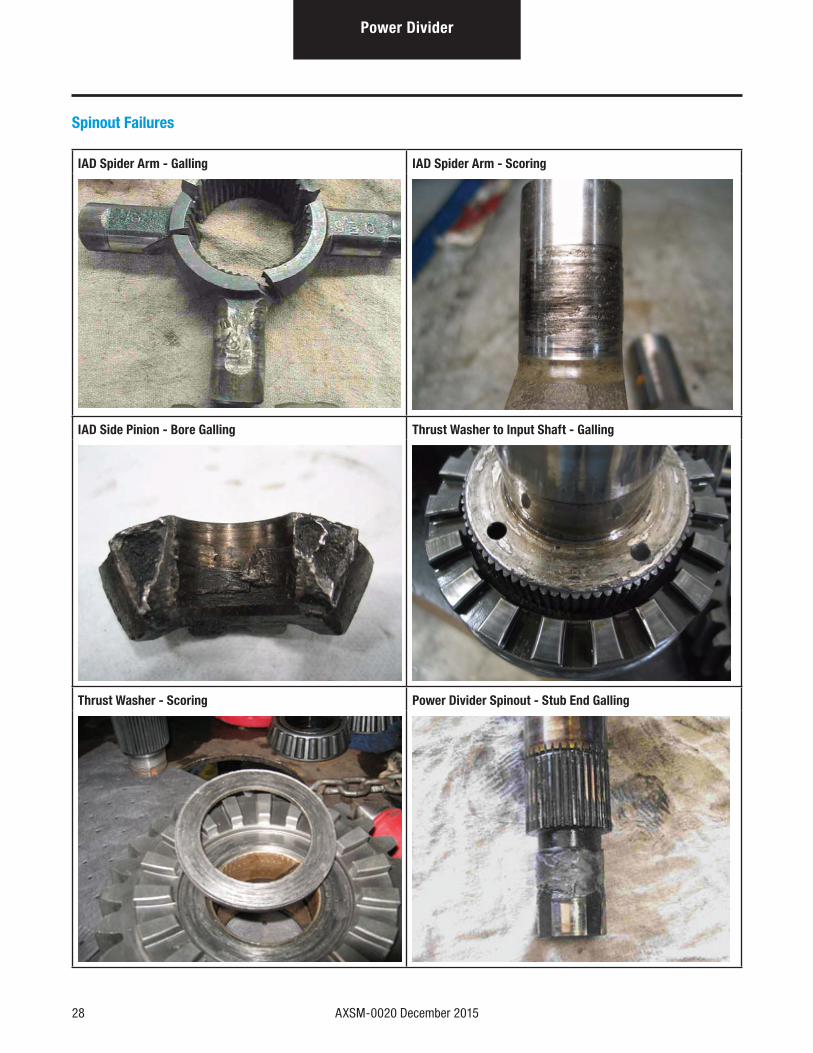
Spinout Failures
IAD Spider Arm - Galling IAD Spider Arm - Scoring
IAD Side Pinion - Bore Galling Thrust Washer to Input Shaft - Galling
Thrust Washer - Scoring Power Divider Spinout - Stub End Galling
AXSM-0020 December 2015 29
Power D
ividerPower Divider
Spinout Failures (cont'd)
General Description: Spinout is excessive wheel spinning that produces damaging heat. High heat breaks down lube film, allowing damaging metal-to-metal contact. Long-term spinout could produce complete axle breakdown.
Usual Causes: • Single rear axle: Main differential spinout occurs when one wheel remains stationary while the other
wheel is spinning.
• Tandem axles: Spinout occurs in the inter-axle differential when either one wheel or one axle spins
while its mate remains stationary.
Failure Prevention: Drive Practices and Vehicle Operation - see Failure Prevention Section
30 AXSM-0020 December 2015
Power Divider
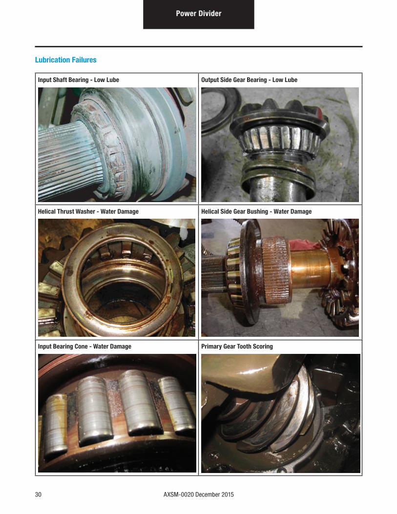
Lubrication Failures
Input Shaft Bearing - Low Lube Output Side Gear Bearing - Low Lube
Helical Thrust Washer - Water Damage Helical Side Gear Bushing - Water Damage
Input Bearing Cone - Water Damage Primary Gear Tooth Scoring
AXSM-0020 December 2015 31
Power D
ividerPower Divider
Lubrication Failures (cont'd)
General Description: Progressive destruction of components due to incorrect lube type, viscosity, or water damage resulting in complete failure.
Usual Causes: • Incorrect lube (wrong viscosity or wrong lube type): Will reduce the life of bearings, gears, bushings, and thrust washers.
• Containment Lube: Water, foreign material, and normal wear or break-in material can cause etching, scoring, or pitting to the contact surfaces. Foreign material in the lube is abrasive.
• Low or no lube: Will create friction which causes overheating, break-down of the protective film, and finally parts seizure of the surfaces of mating parts.
Failure Prevention: Maintenance, Rebuilding, and Adjustment - see Failure Prevention section
32 AXSM-0020 December 2015
Seals & Yokes
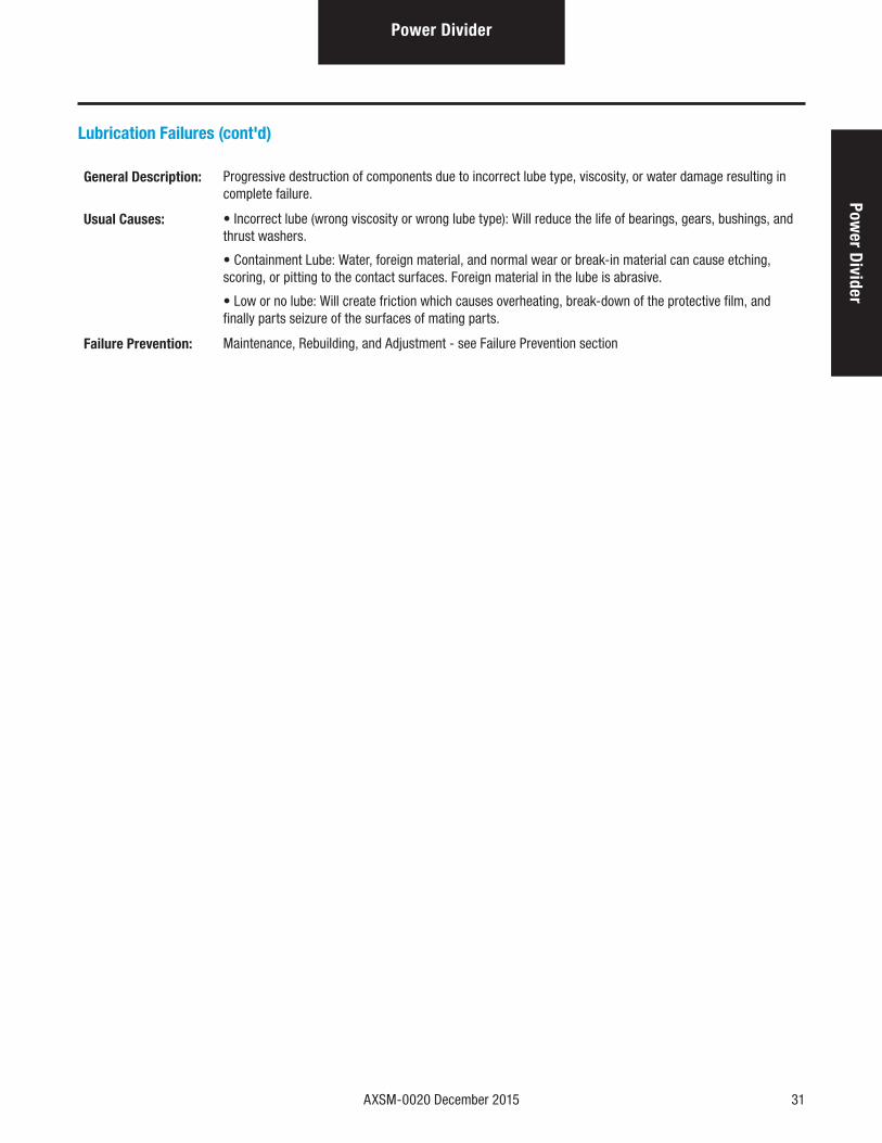
Yoke and Seal Lip Wear
Yoke to Seal Interface - Normal Wear Yoke to Seal Interface - Extreme Wear
Seal Lip - Normal Wear Seal Lip - Extreme Wear
General Description: Yokes and seals will have a shortened wear life if not installed correctly. A worn yoke or seal will also allow contaminants into axle lubricants.
Usual Causes: • Normal Wear: Flattened Edge - Notice the flattened edge of the seal lip indicating incorrect positioning of seal lip against the yoke. Incorrect placement of seal lip will result in lube leakage from the seal or, as shown above, permit dust or dirt to contaminate the lube itself. In order to retain lube and exclude dust and dirt from the system, the seal must be clean, void of defects, and properly installed.
• Extreme Wear: Gap on Seal Lip - Contact area on seal lip is too wide (over 1/32"). This indicates excessive wear or loss of material consistency. The seal must be replaced.
• Scoring: If the yoke displays a rough or scored condition, replace the seal and/or yoke.
Failure Prevention: Maintenance, Rebuilding, and Adjustment - see Failure Prevention Section
AXSM-0020 December 2015 33
Seals & Yokes
Seals & Yokes
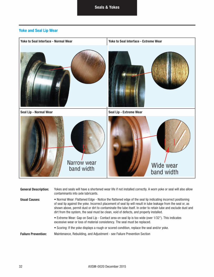
Installation Problems
Bent Outer Shell Dirt Between Seal and Bearing Cage
Coking - Main Lip Installation Damage - Main Lip
Chemical Damage - Main Lip
34 AXSM-0020 December 2015
Installation Problems (cont'd)
General Description: A seal has two critical functions: to retain lube and to exclude dust and dirt. For proper function, the seal must be correctly installed, clean, and free of defects.
Seal Inspection: Careful inspection of seal condition plays an important role in both routine maintenance and failure analysis. Below are some conditions to look for. Check carefully as the smallest defect on the seal lip could cause a leak. In general, any of these observed defects calls for a replacement seal.
• Check for damaged seal lip, bent outer shell, cups and nicks or scoring
• Examine seal edge. A new seal lip has a sharp edge. If sharp edge is flattened greatly, replace the seal.
• Check for hardness or a brittle or cracked lip. This condition is usually caused by excessive temperatures.If the seal lip area is not flexible, replace it.
• Check seal lip contact area. If the contact area is over 1/32", the seal may be excessively worn or the material may have lost its consistency.
• Look for bonding separation of seal to outer shell. This could change the flexibility of the seal lip and cause a leak.
• Check seal spring for fit of the seal on the yoke or low tension. The seal lip may have lost its tension or consistency. Replace it.
• Check inside, under the seal lip, and the casing, for dirt between seal and bearing cage or an accumulation of sludge and other contamination. The seal must be as clean as possible and void of foreign contaminants.
Note: Reference Seal Maintenance Guide TCSM-0912.
Seals & Yokes
AXSM-0020 December 2015 35
BearingsBearings
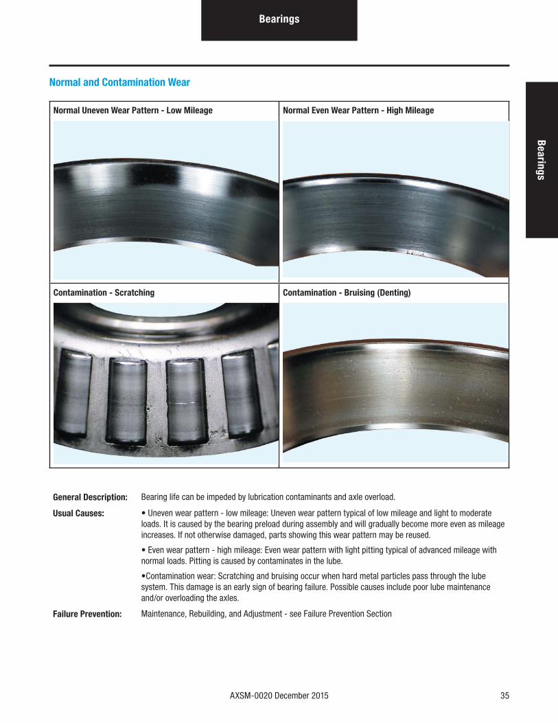
Normal and Contamination Wear
Normal Uneven Wear Pattern - Low Mileage Normal Even Wear Pattern - High Mileage
Contamination - Scratching Contamination - Bruising (Denting)
General Description: Bearing life can be impeded by lubrication contaminants and axle overload.
Usual Causes: • Uneven wear pattern - low mileage: Uneven wear pattern typical of low mileage and light to moderate loads. It is caused by the bearing preload during assembly and will gradually become more even as mileage increases. If not otherwise damaged, parts showing this wear pattern may be reused.
• Even wear pattern - high mileage: Even wear pattern with light pitting typical of advanced mileage with normal loads. Pitting is caused by contaminates in the lube.
•Contamination wear: Scratching and bruising occur when hard metal particles pass through the lube system. This damage is an early sign of bearing failure. Possible causes include poor lube maintenance and/or overloading the axles.
Failure Prevention: Maintenance, Rebuilding, and Adjustment - see Failure Prevention Section
36 AXSM-0020 December 2015
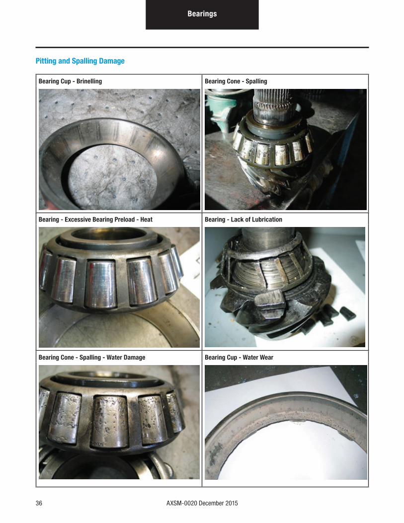
Pitting and Spalling Damage
Bearing Cup - Brinelling Bearing Cone - Spalling
Bearing - Excessive Bearing Preload - Heat Bearing - Lack of Lubrication
Bearing Cone - Spalling - Water Damage Bearing Cup - Water Wear
Bearings
AXSM-0020 December 2015 37
BearingsBearings
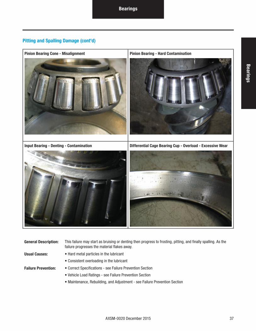
Pitting and Spalling Damage (cont'd)
Pinion Bearing Cone - Misalignment Pinion Bearing - Hard Contamination
Input Bearing - Denting - Contamination Differential Cage Bearing Cup - Overload - Excessive Wear
General Description: This failure may start as bruising or denting then progress to frosting, pitting, and finally spalling. As the failure progresses the material flakes away.
Usual Causes: • Hard metal particles in the lubricant
• Consistent overloading in the lubricant
Failure Prevention: • Correct Specifications - see Failure Prevention Section
• Vehicle Load Ratings - see Failure Prevention Section
• Maintenance, Rebuilding, and Adjustment - see Failure Prevention Section
38 AXSM-0020 December 2015
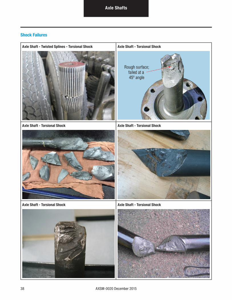
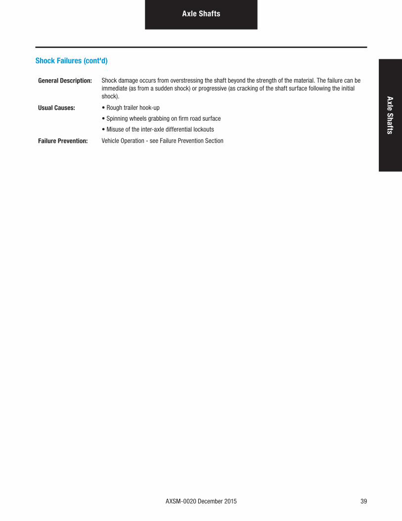
Shock Failures
Axle Shaft - Twisted Splines - Torsional Shock Axle Shaft - Torsional Shock
Axle Shaft - Torsional Shock Axle Shaft - Torsional Shock
Axle Shaft - Torsional Shock Axle Shaft - Torsional Shock
Axle Shafts
AXSM-0020 December 2015 39
Shock Failures (cont'd)
General Description: Shock damage occurs from overstressing the shaft beyond the strength of the material. The failure can be immediate (as from a sudden shock) or progressive (as cracking of the shaft surface following the initial shock).
Usual Causes: • Rough trailer hook-up
• Spinning wheels grabbing on firm road surface
• Misuse of the inter-axle differential lockouts
Failure Prevention: Vehicle Operation - see Failure Prevention Section
Axle ShaftsA
xle Shafts
40 AXSM-0020 December 2015
Drive Axle Housing
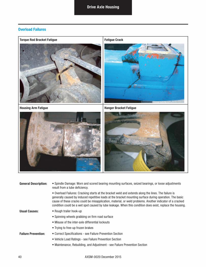
Overload Failures
Torque Rod Bracket Fatigue Fatigue Crack
Housing Arm Fatigue Hanger Bracket Fatigue
General Description: • Spindle Damage: Worn and scored bearing mounting surfaces, seized bearings, or loose adjustments result from a lube deficiency.
• Overload Failures: Cracking starts at the bracket weld and extends along the lines. The failure is generally caused by induced repetitive loads at the bracket mounting surface during operation. The basic cause of these cracks could be misapplication, material, or weld problems. Another indicator of a cracked condition could be a wet spot caused by lube leakage. When this condition does exist, replace the housing.
Usual Causes: • Rough trailer hook-up
• Spinning wheels grabbing on firm road surface
• Misuse of the inter-axle differential lockouts
• Trying to free-up frozen brakes
Failure Prevention: • Correct Specifications - see Failure Prevention Section
• Vehicle Load Ratings - see Failure Prevention Section
• Maintenance, Rebuilding, and Adjustment - see Failure Prevention Section
AXSM-0020 December 2015 41
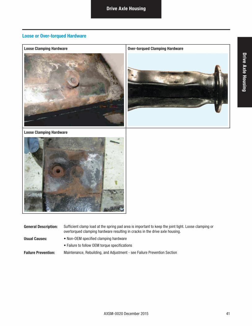
Loose or Over-torqued Hardware
Loose Clamping Hardware Over-torqued Clamping Hardware
Loose Clamping Hardware
General Description: Sufficient clamp load at the spring pad area is important to keep the joint tight. Loose clamping or overtorqued clamping hardware resulting in cracks in the drive axle housing.
Usual Causes: • Non-OEM specified clamping hardware
• Failure to follow OEM torque specifications
Failure Prevention: Maintenance, Rebuilding, and Adjustment - see Failure Prevention Section
Drive Axle HousingD
rive Axle Housing
42 AXSM-0020 December 2015
Steer Axle
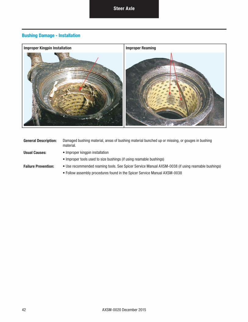
Bushing Damage - Installation
Improper Kingpin Installation Improper Reaming
General Description: Damaged bushing material, areas of bushing material bunched up or missing, or gouges in bushing material.
Usual Causes: • Improper kingpin installation
• Improper tools used to size bushings (if using reamable bushings)
Failure Prevention: • Use recommended reaming tools. See Spicer Service Manual AXSM-0038 (if using reamable bushings)
• Follow assembly procedures found in the Spicer Service Manual AXSM-0038
AXSM-0020 December 2015 43
Steer AxleSteer A
xle
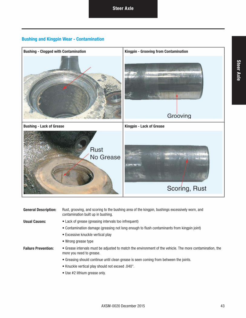
Bushing and Kingpin Wear - Contamination
Bushing - Clogged with Contamination Kingpin - Grooving from Contamination
Bushing - Lack of Grease Kingpin - Lack of Grease
General Description: Rust, grooving, and scoring to the bushing area of the kingpin, bushings excessively worn, and contamination built up in bushing.
Usual Causes: • Lack of grease (greasing intervals too infrequent)
• Contamination damage (greasing not long enough to flush contaminants from kingpin joint)
• Excessive knuckle vertical play
• Wrong grease type
Failure Prevention: • Grease intervals must be adjusted to match the environment of the vehicle. The more contamination, the more you need to grease.
• Greasing should continue until clean grease is seen coming from between the joints.
• Knuckle vertical play should not exceed .040".
• Use #2 lithium grease only.
44 AXSM-0020 December 2015
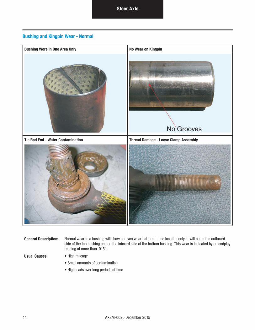
Bushing and Kingpin Wear - Normal
Bushing Wore in One Area Only No Wear on Kingpin
Tie Rod End - Water Contamination Thread Damage - Loose Clamp Assembly
General Description: Normal wear to a bushing will show an even wear pattern at one location only. It will be on the outboard side of the top bushing and on the inboard side of the bottom bushing. This wear is indicated by an endplay reading of more than .015".
Usual Causes: • High mileage
• Small amounts of contamination
• High loads over long periods of time
Steer Axle

Printed in USA AXSM-0020 12/15
For spec’ing or service assistance, call 1-877-777-5360 or visit our website at www.dana.com/cv
Dana Commercial Vehicle Products Group3939 Technology DriveMaumee, Ohio, USA 43537
www.dana.com/cv
Application PolicyCapacity ratings, features, and specifications vary depending upon the model and type of service. Application approvals must be obtained from Dana; contact your representative for application approval. We reserve the right to change or modify our product specifications, configurations, or dimensions at any time without notice.