CRANKSHAFT 20V34SG FAILURE
6
1 CRANKSHAFT 20V34SG FAILURE 1.- BACKGROUND A 20V34SG Crankshaft has failed with about 3500 hours of work at a Power Plant, in Turkey. The cracking was at the crankthrow no. 4, but it did not break completely. At the moment of visual inspection the piece part (two crankthrows) was in a supplier shop. As the crack was quite far from finish through the section and there was not a press to force the cracking, then it was necessary to plan a succession of partial cuts with saw. After discover the crack turning around the section, the parts had to be finally separated by cold cutters to break two unbroken bridges between crack facets. 2.- VISUAL INSPECTION The cutting procedure was led in order to preserve specially the initiation points but it was impossible to obtain the Fig. 1: Separation of parts by cold cutters. B A B A Fig. 2: Fracture faces (the yellow and blue lines shown the crack continuation). “A” and “B” are two levels of crack propagation.
-
Upload
independent -
Category
Documents
-
view
0 -
download
0
Transcript of CRANKSHAFT 20V34SG FAILURE
1
CRANKSHAFT 20V34SG FAILURE
1.- BACKGROUND A 20V34SG Crankshaft has failed with about 3500 hours of work at a Power Plant, in Turkey. The cracking was at the crankthrow no. 4, but it did not break completely. At the moment of visual inspection the piece part (two crankthrows) was in a supplier shop. As the crack was quite far from finish through the section and there was not a press to force the cracking, then it was necessary to plan a succession of partial cuts with saw. After discover the crack turning around the section, the parts had to be finally separated by cold cutters to break two unbroken bridges between crack facets. 2.- VISUAL INSPECTION The cutting procedure was led in
order to preserve specially the initiation points but it was impossible to obtain the
Fig. 1: Separation of parts by cold cutters.
B A
B
A
Fig. 2: Fracture faces (the yellow and blue lines shown the crack continuation). “A”
and “B” are two levels of crack propagation.

2
CRANKSHAFT 20V34SG FAILURE
whole crack faces. In the Fig. 2 the yellow lines showed the crack continuation. As the rugosity of the sawn surface was high it is supposed the crack would also continue along the blue line, but we could not see it.
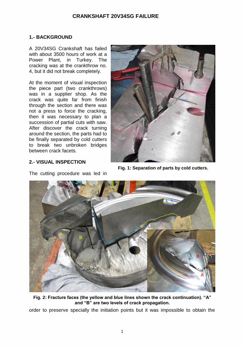
In any case, it is very difficult to imagine how the crack had continued outside the shown faces, but one thing is true that the transversal crack has arrived to the circumferential points at 90º from the maximum bending moment point (MBP), where it derived to the longitudinal developing. As the advance of individual transversal cracks had arrived to the change point (at the left hand end) at several levels then each crack front changed to longitudinal direction at its own level, as shown in Fig. 2 A and B levels. The transversal crack continued until the oil bore (“C” trajectory in Fig 3 a). “D” and “E” were the last bridges that were necessary to broke until separate the two pieces. For this reason they are lift from their natural position. The matching positions shown in Fig 3 b) indicate that these crack fronts had stopped at these points. In Fig 3 a) it is also shown the change in crack direction of the “B” level. 3.- CRACK DEVELOPING It can be supposed the crack started at the point “O” (Fig. 4), approximately at 45º from the “MBP” of the crankthrow, because at this point the cracking “stage I” has the maximum width and diminishes as it goes to point “F” (to continue until the oil bore) and to “MBP” (being negligible further than this point) continuing to point “G”. It is also found that the “O” point is in the crankpin at 25 mm from the fillet radius edge. The “stage II” propagated on multiple cleavage plateaus, which are at different levels with respect to one another, in the radial direction (“R” arrows in Fig 5). These plateaus became joined by tear ridges.
D
E
C
B D
E
a) b)
Fig. 3: Other crack features.

3
CRANKSHAFT 20V34SG FAILURE
Some crack fronts (those of the central zone with “R” marks in Fig 5) continued inside the unbroken piece but they did not arrive to the surface. Against that, the crack fronts at “G” zone changed their direction to longitudinal and they had arrived to the fillet radius, but it is impossible to know how far it has advanced to the left side.
Maximum bending moment point
Crack starting point
MBP
G
F
O
Fig. 4: Fracture staring point and first cracking stages.
B
A
B
A
R
R
R
G
Fig. 5: Fracture faces of the “stage II” of crack propagation. In the lower right corner
detailed image the developed of “A” and “B” levels are shown.
H
J

4
CRANKSHAFT 20V34SG FAILURE
The plateaus of level “A” and “B” also changed their direction to the longitudinal one. The “B” level only arrived to the plateau border shown in Fig 5 (see in the lower right corner a detailed image the developed of “A” and “B”), but the “A” level has developed and it arose to the web end surface. At its right side it also continued to the web centre, but it is possible that its front did not go very much further than point “H” because in the upper part the front had stopped at “J” (because the unbroken tip).
4.- ANOTHER POINTS OF INTEREST After the dismantling the pieces of engine in order to take out the broken crankshaft it was shown a severe seizure of A4 and B4 both upper and lower bearings (Fig 6), being the wear more pronounced in the lower parts. The aspect of this seizing is like the copper alloy layer had debonded and it had been taken off by flakes. These debris went to the oiling flow and could block the oil bores. It was also shown that the B4 piston (Fig 7) had severe erosion and the material had been dragged from the bottom to the oil ring groove, filling this. This could be caused because the debris has blocked the oil flow to the piston, then, the friction against the cylinder liner, harder than the piston, has eroded this one.
A4L
B4U
B4L
Fig. 6: Bearing seizure.

5
CRANKSHAFT 20V34SG FAILURE
In the crankpin it was shown big adhesions, but the B side had more adhesive wears than the A side. A big adhesion was also found at the middle of crankpin (Fig 7). In this condition, the high friction could have produced overheatings. The purple and dark blue colours means that the temperature has raised around 290 ºC (tempering colours) lowering the strength of the steel.
The Metals Handbook has several references to bearing seizure:
Wear failures result from the removal or displacement of surface material through contact and relative motion with a solid, liquid, or gas. There is a significant influence of friction and lubrication on the rate and severity of wear damage. Wear generally results in loss of material and load-carrying capability, adhesion, increased friction, and debris generation. Whether or not wear damage constitutes failure of a component depends on the performance criteria of the component, such as in a failed diesel engine main bearing that sustained excessive wear and a subsequent loss of control of the crankshaft radial movement (ASM Metals HandBook, 2002 edition, Vol 11: Failure Analysis and Prevention, p-55, Wear failure) Another cases of bearing seizures (ASM Metals HandBook, 2002 edition, Vol 11: Failure Analysis and Prevention, p-2352, Wear failure)(chapter beginning, p-2344):
A4 B4
B4
Fig. 7: Adhesions at piston and crankpin.

6
CRANKSHAFT 20V34SG FAILURE
Fatigue cracking of bimetal bearings occurs in stages, beginning with a hen-track pattern on the bearing surface. As fatigue progresses the soft metal separates from the hard backing by flaking. This may occur even though lubrication is adequate, but operation with very thin fluid films could cause heating and weakening of the bearing material.
In a case of bearings for a diesel engine that failed because of distortion or misalignment of the crankcase, the central bearing halves sustained greater damage than the end halves.
5.- CRACKING CAUSES Independent of the results from the crankshaft material, it is possible that such a lot adhesive weldings at crankpin had produced a great amount of heat, overheating the crankpin and diminishing the steel strength. Every time a welding spot was broken, a torsional stress pick was applied to the crankpin that could produce torsional vibration. These effects could raise the applied torsional stresses to this crankpin that added to the normal loading stresses could start the fatigue cracking in the crankpin, specially if we take into account the strength lowering because the overheating.
Report done and signed by Javier Tezanos