Pneumatic Metal Circular Saw - Type 5 1117 0020 - CS Unitec
23
Translation of the original manual, compiled: 20.09.17 511170020_Inst_en_Version_CSU_02.doc Pneumatic Metal Circular Saw Type 5 1117 0020 Illustration can differ from the original Repair Instruction and Spare Parts List
-
Upload
khangminh22 -
Category
Documents
-
view
1 -
download
0
Transcript of Pneumatic Metal Circular Saw - Type 5 1117 0020 - CS Unitec

Translation of the original manual, compiled: 20.09.17
511170020_Inst_en_Version_CSU_02.doc
Pneumatic Metal Circular Saw
Type 5 1117 0020
Illustration can differ from the original
Repair Instruction and Spare Parts List

P n e u m a t i c Meta l Ci rcu lar Saw 5 1117 0020
Translation of the original manual, compiled: 20.09.17
511170020_Inst_en_Version_CSU_02.doc Page 1 of 22
Repair
Disassembly Disassembly and re-assembly should only be performed with assistance of the sectional drawing and/or the exploded view. Observe the safety instructions of the operation and maintenance manual.
Do not disassemble the tool until you know whether the problem is in one of the modules. Then only disassemble the tool as necessary to repair as required. Keep contaminants such as dirt and grit away from the internal parts at all times.
Always identify and correct the cause of the problem prior to re-assembling. Further wear and tool failure can result, if the original cause is not corrected.
Prior to separating the modules, determine exactly, if the problem is in the compressed air supply in one of the modules. The paragraph “Troubleshooting” of the operation manual contains helpful information for exact identification of the problem. Prior to disassembly Clean outer surface of the machine.
Make sure that all new sealings are available for replacing the old ones during re-assembly. Consider the installation direction of the sealings, before removing them. Install the new sealings at the same position as the old ones.
Notice: The installation direction of the parts mentioned in the following process instructions is indicated in the sectional drawings and parts list at the end of this instruction.
Spare Parts Only genuine spare parts may be used. There is no warranty for damages and liability is disclaimed, if non-original spare parts and accessories are used.

P n e u m a t i c Meta l Ci rcu lar Saw 5 1117 0020
Translation of the original manual, compiled: 20.09.17
511170020_Inst_en_Version_CSU_02.doc Page 2 of 22
Disassembly
Preparation of the metal saw for disassembly
Disconnect energy supply and secure against restart.
Disconnect pneumatic hoses.
Take cutting tool out of the tool holder and store it at a safe place.
Disassembling of the modules for the attachment
Loosen 7 x M5 item 29 (page 15) and remove motor housing cover item 28 from motor item 1 (page 13).
Pull connecting pipe item 3 (page 13) out of the sealing sleeve item 4 (page 13)
Loosen item 8 and 10 (page 13) and then remove valve handle, assy., item 2
Disassembling of the motor item 1
Loosen 7 x M5 item 29 and dismantle motor housing cover item 28
Pull item 2 – 20 out of the motor housing item 1 (page 15).
If necessary, continue disassembling the motor according to the component drawing.
Disassemble valve handle, assy., item 2
Loosen 1 x M5 item 304 (page 17) and remove the handle, assy. item 306 with item 301 - 303 from the control, assy. item 305.
If necessary, continue disassembling the valve handle, assy., according to the component drawing.
Disassembling of control, assy. Item 305
Loosen the hollow screw item 315 and remove the pivoting connection item 314 with item 312-313 from the valve housing, assy. Item 301.
Pull item 302 – 307 out of the valve housing, assy., item 301.
If necessary, continue disassembling the control, assy., according to the component drawing.
Disassembling of handle item 306
Beat the double notched tape pin item 603 (page 21).
Loosen the pressure sleeve item 606.
If necessary, continue disassembling the handle, assy., according to the component drawing.

P n e u m a t i c Meta l Ci rcu lar Saw 5 1117 0020
Translation of the original manual, compiled: 20.09.17
511170020_Inst_en_Version_CSU_02.doc Page 3 of 22
Re-assembly
The re-assembly is done in the reverse order.
Observe the following:
Check o-rings, bearings and radial shaft sealings with regard to damages and replace, if necessary.
When using assembly aids:
Assembly aids must not cause damages.
Wear parts –especially the vanes – have to be replaced in time. Vanes are considered worn, when their width is less than 9.5 mm.
After use, flush the motor with thin fluid oil or provide a comparable corrosion protection.
The rotor slots have to be cleaned from oil and resin residues, before installing the vanes item 15. The new vanes have to fall easily into the slots. Position the cylinder bushing item 7 correctly.
Further, the following items have to be observed!
If the bearings item 3 and item 17 in the end plates item 2 and 16 have been replaced, the spacing has to be checked in any case. If necessary, the spacing has to be corrected by installing new spacer rings item 6 and 19 (see fig. “end plate with spacer ring”).
The spacer ring should be placed 0.04 / 0.05 mm in front of the end plate. For this, the inner ball bearing ring has to be pressed into the direction of the snap ring.
repla
ce
Insta
llation
new

P n e u m a t i c Meta l Ci rcu lar Saw 5 1117 0020
Translation of the original manual, compiled: 20.09.17
511170020_Inst_en_Version_CSU_02.doc Page 4 of 22
After finishing the assembly, a functional check must be done. In most of the cases a check of the specified free speed and the air consumption is sufficient. (see technical specification of the operation manual).
Tighten all screws and nuts according to the instructions, when re-assembling.
Tightening torques
Item Description Torque Remark
8 Socket head screw M5 6,5 Nm Page 13
10 Counter sunk screw M5 6,5 Nm Page 13
23 Socket head screw M6 11,5 Nm Page 15
26 Socket head screw M5 6,5 Nm Page 15
29 Socket head screw M5 6,5 Nm Page 15
303 Counter sunk screw M5 6,5 Nm Page 17
304 Socket head screw M5 6,5 Nm Page 17
Lubricant The proper quantity of grease is very important from the point of good lubrication and low heat generation. It is important that the individual gear stages can be turned easily. Pay attention to the centred running of the pinion and the planet wheel carrier. The gear has to be filled with grease (see following table).
Grease
Quantity of grease Order number
10 g 9 9902 0110
End plate with spacer ring

P n e u m a t i c Meta l Ci rcu lar Saw 5 1117 0020
Translation of the original manual, compiled: 20.09.17
511170020_Inst_en_Version_CSU_02.doc Page 5 of 22
Spare Parts List Description: Part and drawing number:
Pneumatic Metal Circular Saw 5 1117 0020
Item Qty. Description Part and drawing no. Remarks
1 Pneumatic metal circular saw 5 1117 0020
consisting of:
1 1 Metal circular saw 5 1117 9000 see extra list
2 1 Modification kit for metal circular saw 5 1117 6800 see extra list
3 1 Nipple, assy. 9 2205 2250 NPT- 1/2
Accessory
4 1 Circular saw blade 9 2503 0140

P n e u m a t i c Meta l Ci rcu lar Saw 5 1117 0020
Translation of the original manual, compiled: 20.09.17
511170020_Inst_en_Version_CSU_02.doc Page 6 of 22
Spare Parts List Description: Part and drawing number:
Pneumatic Metal Circular Saw 5 1117 0020

P n e u m a t i c Meta l Ci rcu lar Saw 5 1117 0020
Translation of the original manual, compiled: 20.09.17
511170020_Inst_en_Version_CSU_02.doc Page 7 of 22
Spare Parts List Description: Part and drawing number:
Metal Circular Saw Head 5 1117 9000
Item Qty. Description Part and drawing no. Remarks
12 2 Washer 9 3325 1670
21 3 Crosshead screw 9 1149 0070
22 1 Holder 5 1117 8950
23 1 Washer 9 3302 0150
24 1 Dust port plug 5 1117 8930
25 1 Dust chamber cover 5 1117 8940
26 1 Front guard 5 1117 8920
27 1 Cover plate 5 1117 8070
28 7 Crosshead screw 9 1149 0060
29 1 Socket head screw 9 1110 5040
30 1 Spring washer 9 3322 0030
31 1 Disc 5 1117 8040
32 1 Wheel flange 5 1117 8050
34 1 Centring flange 5 1117 8030
35 3 Counter sunk screw 9 1113 2070
36 1 Disc 5 1117 8320
37 1 Bottom guard 5 1117 8310
38 1 Tension spring 9 1804 0240
39 5 Socket head screw 9 1110 2090
40 1 Adjusting mechanism 5 1117 8240
41 2 Snap ring 9 1702 0040
42 1 Bolt 5 1117 8250
43 1 Adjusting lever 5 1117 8220
44 4 Socket head screw 9 1110 3170
45 1 Socket head screw 9 1110 4010
46 1 Rubber buffer 9 5201 0080
47 1 Rear guard 5 1117 8910
48 5 Crosshead screw 9 1149 0080
49 1 Handle 5 1117 6210

P n e u m a t i c Meta l Ci rcu lar Saw 5 1117 0020
Translation of the original manual, compiled: 20.09.17
511170020_Inst_en_Version_CSU_02.doc Page 8 of 22
Spare Parts List Description: Part and drawing number:
Metal Circular Saw Head 5 1117 9000
Item Qty. Description Part and drawing no. Remarks
50 1 Connecting gear housing 5 1117 4910
51 1 Spindle 5 1117 7020
52 3 Feather key 9 1501 3030
53 2 Grooved ball bearing 9 1004 0290
54 1 Snap ring 9 1702 0170
55 1 Spacer sleeve 5 1117 4220
56 1 Spur wheel 5 1117 4200
57 1 Nut 5 1117 4210
58 2 Grooved ball bearing 9 1001 0120 *
59 1 Gear pinion 5 1117 4170
60 1 Gear wheel 5 1117 4270
61 1 Grooved ball bearing 9 1004 0300 *
62 1 Gear cover 5 1117 4090
63 1 Grooved ball bearing 9 1003 0390 *
64 1 Locking lever 5 1117 8100
72 2 Adjusting washer 9 3331 2500
79 2 Socket head screw 9 1110 3120
80 1 Guide bar 5 1117 8260
81 2 Crosshead screw 9 1149 0090
82 2 Spring washer 9 3312 0010
83 2 Lock 9 1149 0100
84 1 Threaded pin 9 1140 3040
85 1 Bolt 5 1117 8230
86 1 Base plate 5 1117 8210
87 1 Rubber disc 5 1117 8270
* Wear parts to be stored in case of
continuous operation.

P n e u m a t i c Meta l Ci rcu lar Saw 5 1117 0020
Translation of the original manual, compiled: 20.09.17
511170020_Inst_en_Version_CSU_02.doc Page 9 of 22
Spare Parts List Description: Part and drawing number:
Metal Circular Saw Head 5 1117 9000

P n e u m a t i c Meta l Ci rcu lar Saw 5 1117 0020
Translation of the original manual, compiled: 20.09.17
511170020_Inst_en_Version_CSU_02.doc Page 10 of 22
Spare Parts List Description: Part and drawing number:
Metal Circular Saw Head 5 1117 9000

P n e u m a t i c Meta l Ci rcu lar Saw 5 1117 0020
Translation of the original manual, compiled: 20.09.17
511170020_Inst_en_Version_CSU_02.doc Page 11 of 22
Spare Parts List Description: Part and drawing number:
Metal Circular Saw Head 5 1117 9000

P n e u m a t i c Meta l Ci rcu lar Saw 5 1117 0020
Translation of the original manual, compiled: 20.09.17
511170020_Inst_en_Version_CSU_02.doc Page 12 of 22
Spare Parts List Description: Part and drawing number:
Modification Kit for Metal Circular Saw 5 1117 6800
Item Qty. Description Part and drawing no. Remarks
1 1 Pneumatic motor 5 1117 1000 see extra list
2 1 Valve handle, assy. 5 1117 3900 see extra list
3 1 Connection pipe 5 1117 1240
4 1 Sealing sleeve 5 1117 1140
5 3 O-ring 9 1901 2120 *
7 1 Spacer pipe 5 1117 3040
8 1 Socket head screw 9 1110 3370
9 1 Locking washer 9 3329 0010
10 1 Counter sunk screw 9 1113 3100
11 1 Spacer pipe 5 1117 3060
12 1 Palm grip screw 5 1117 6820
* Wear parts to be stored in case of
continuous operation.

P n e u m a t i c Meta l Ci rcu lar Saw 5 1117 0020
Translation of the original manual, compiled: 20.09.17
511170020_Inst_en_Version_CSU_02.doc Page 13 of 22
Spare Parts List Description: Part and drawing number:
Modification Kit for Metal Circular Saw 5 1117 6800
P n e u m a t i c Meta l Ci rcu lar Saw 5 1117 0020
Translation of the original manual, compiled: 20.09.17
511170020_Inst_en_Version_CSU_02.doc Page 14 of 22
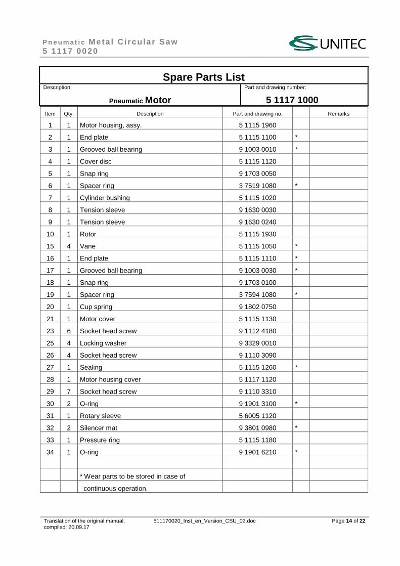
Spare Parts List Description: Part and drawing number:
Pneumatic Motor 5 1117 1000
Item Qty. Description Part and drawing no. Remarks
1 1 Motor housing, assy. 5 1115 1960
2 1 End plate 5 1115 1100 *
3 1 Grooved ball bearing 9 1003 0010 *
4 1 Cover disc 5 1115 1120
5 1 Snap ring 9 1703 0050
6 1 Spacer ring 3 7519 1080 *
7 1 Cylinder bushing 5 1115 1020
8 1 Tension sleeve 9 1630 0030
9 1 Tension sleeve 9 1630 0240
10 1 Rotor 5 1115 1930
15 4 Vane 5 1115 1050 *
16 1 End plate 5 1115 1110 *
17 1 Grooved ball bearing 9 1003 0030 *
18 1 Snap ring 9 1703 0100
19 1 Spacer ring 3 7594 1080 *
20 1 Cup spring 9 1802 0750
21 1 Motor cover 5 1115 1130
23 6 Socket head screw 9 1112 4180
25 4 Locking washer 9 3329 0010
26 4 Socket head screw 9 1110 3090
27 1 Sealing 5 1115 1260 *
28 1 Motor housing cover 5 1117 1120
29 7 Socket head screw 9 1110 3310
30 2 O-ring 9 1901 3100 *
31 1 Rotary sleeve 5 6005 1120
32 2 Silencer mat 9 3801 0980 *
33 1 Pressure ring 5 1115 1180
34 1 O-ring 9 1901 6210 *
* Wear parts to be stored in case of
continuous operation.

P n e u m a t i c Meta l Ci rcu lar Saw 5 1117 0020
Translation of the original manual, compiled: 20.09.17
511170020_Inst_en_Version_CSU_02.doc Page 15 of 22
Spare Parts List Description: Part and drawing number:
Pneumatic Motor 5 1117 1000

P n e u m a t i c Meta l Ci rcu lar Saw 5 1117 0020
Translation of the original manual, compiled: 20.09.17
511170020_Inst_en_Version_CSU_02.doc Page 16 of 22
Spare Parts List Description: Part and drawing number:
Valve Handle, Assy. 5 1117 3900
Item Qty. Description Part and drawing no. Remarks
301 1 Connection lug 5 1117 6040
302 1 Holder 5 1117 3030
303 4 Counter sunk screw 9 1113 3010
304 1 Socket head screw 9 1112 3020
305 1 Control, assy. 5 1117 3000 see extra list
306 1 Handle, assy. 2 1317 6920 see extra list

P n e u m a t i c Meta l Ci rcu lar Saw 5 1117 0020
Translation of the original manual, compiled: 20.09.17
511170020_Inst_en_Version_CSU_02.doc Page 17 of 22
Spare Parts List Description: Part and drawing number:
Valve Handle, Assy. 5 1117 3900

P n e u m a t i c Meta l Ci rcu lar Saw 5 1117 0020
Translation of the original manual, compiled: 20.09.17
511170020_Inst_en_Version_CSU_02.doc Page 18 of 22
Spare Parts List Description: Part and drawing number:
Control, Assy. 5 1117 3000
Item Qty. Description Part and drawing no. Remarks
301 1 Valve housing, assy. 5 1117 3920
302 1 Valve bushing 5 1117 1013
303 1 Valve piston 5 1117 3010
304 3 O-ring 9 1901 2940
305 3 O-ring 9 1901 2270
306 1 Pressure spring 9 1803 3810
307 1 Snap ring 9 1703 0360
312 1 O-ring 9 1901 5210
313 2 O-ring 9 1901 3660
314 1 Pivoting connection 2 3010 3060
315 1 Hollow screw 2 3010 3080

P n e u m a t i c Meta l Ci rcu lar Saw 5 1117 0020
Translation of the original manual, compiled: 20.09.17
511170020_Inst_en_Version_CSU_02.doc Page 19 of 22
Spare Parts List Description: Part and drawing number:
Control, Assy. 5 1117 3000

P n e u m a t i c Meta l Ci rcu lar Saw 5 1117 0020
Translation of the original manual, compiled: 20.09.17
511170020_Inst_en_Version_CSU_02.doc Page 20 of 22
Spare Parts List Description: Part and drawing number:
Handle, Assy. 2 1317 6920
Item Qty. Description Part and drawing no. Remarks
601 1 Handle 2 1317 6110
602 1 Valve trigger 2 1317 3030
603 1 Double notched taper pin 9 1641 0010
604 1 Threaded pin 9 1140 3060
605 1 Locking slide 5 1216 3150
606 1 Pressure sleeve 5 1216 3160
607 1 Guide sleeve 5 1216 3170
608 1 Pressure spring 9 1803 3360
609 1 Screw button 5 1216 3180

P n e u m a t i c Meta l Ci rcu lar Saw 5 1117 0020
Translation of the original manual, compiled: 20.09.17
511170020_Inst_en_Version_CSU_02.doc Page 21 of 22
Spare Parts List Description: Part and drawing number:
Handle, Assy. 2 1317 6920
Note:

Translation of the original manual, compiled: 20.09.17
511170020_Inst_en_Version_CSU_02.doc
CS Unitec, Inc. 22 Harbor Ave, Norwalk, CT 06850 USA
Toll-free: 1-800-700-5919 (USA & Canada) Phone: 203-853-9522 (outside USA & Canada) Fax: 203-853-992