
BT.1117-2 - Studio format parameters for enhanced 16:9 ... - ITU
31
Rec. ITU-R BT.1117-2 1 RECOMMENDATION ITU-R BT.1117-2 STUDIO FORMAT PARAMETERS FOR ENHANCED 16:9 ASPECT RATIO 625-LINE TELEVISION SYSTEMS (D- AND D2-MAC, PALplus, ENHANCED SECAM) (Question ITU-R 42/11) (1994-1995-1997) Rec. ITU-R BT.1117-2 The ITU Radiocommunication Assembly, considering a) that there are already broadcast services offering 16:9 programmes; b) that there are proposals to introduce new systems of television broadcasting with improved quality of picture and sound, including a wider aspect ratio; c) that most broadcasting organizations are committed to maintaining a service to their viewers with receiving installations equipped only for terrestrial reception; d) that many broadcasting organizations will wish to enhance the quality of their existing services; e) that enhancements of existing terrestrial standards must remain compatible with current channel allocations; f) that enhancements of existing terrestrial standards must maintain a high degree of picture compatibility; g) that the principal enhancements identified as means of delivering improved images and sound by enhanced television emission include: picture – wider aspect ratio, – reduced cross effects, – ghost cancellation, – enhanced resolution; sound – digital, multi-channel sound; h) that so far, completely satisfactory decoding of PAL and SECAM encoded signals has not been achieved; j) that it is desirable that there be the maximum commonality of studio format parameters for different transmission/emission standards, for example, the MAC/packet and PALplus systems; k) that changes to studio/production format and practices can improve the compatibility of an enhanced television signal and thus facilitate the introduction of enhanced systems; l) that the provision of an improved studio format will assist the process of up-conversion to HDTV, recommends 1 that organizations intending to produce programmes for enhanced television services should adopt component standards using some, or all, of the techniques given in Annex 1. A short analysis of when and where each option should be used is given in Annex 3, invites 1 administrations to make contributions on this matter with a view to completion of this Recommendation.
-
Upload
khangminh22 -
Category
Documents
-
view
0 -
download
0
Transcript of BT.1117-2 - Studio format parameters for enhanced 16:9 ... - ITU
Rec. ITU-R BT.1117-2 1
RECOMMENDATION ITU-R BT.1117-2
STUDIO FORMAT PARAMETERS FOR ENHANCED 16:9 ASPECT RATIO 625-LINE TELEVISION SYSTEMS (D- AND D2-MAC, PALplus,
ENHANCED SECAM)
(Question ITU-R 42/11)
(1994-1995-1997) Rec. ITU-R BT.1117-2
The ITU Radiocommunication Assembly,
considering
a) that there are already broadcast services offering 16:9 programmes;
b) that there are proposals to introduce new systems of television broadcasting with improved quality of picture and sound, including a wider aspect ratio;
c) that most broadcasting organizations are committed to maintaining a service to their viewers with receiving installations equipped only for terrestrial reception;
d) that many broadcasting organizations will wish to enhance the quality of their existing services;
e) that enhancements of existing terrestrial standards must remain compatible with current channel allocations;
f) that enhancements of existing terrestrial standards must maintain a high degree of picture compatibility;
g) that the principal enhancements identified as means of delivering improved images and sound by enhanced television emission include:
picture – wider aspect ratio,
– reduced cross effects,
– ghost cancellation,
– enhanced resolution;
sound – digital, multi-channel sound;
h) that so far, completely satisfactory decoding of PAL and SECAM encoded signals has not been achieved;
j) that it is desirable that there be the maximum commonality of studio format parameters for different transmission/emission standards, for example, the MAC/packet and PALplus systems;
k) that changes to studio/production format and practices can improve the compatibility of an enhanced television signal and thus facilitate the introduction of enhanced systems;
l) that the provision of an improved studio format will assist the process of up-conversion to HDTV,
recommends
1 that organizations intending to produce programmes for enhanced television services should adopt component standards using some, or all, of the techniques given in Annex 1. A short analysis of when and where each option should be used is given in Annex 3,
invites
1 administrations to make contributions on this matter with a view to completion of this Recommendation.
2 Rec. ITU-R BT.1117-2
ANNEX 1
Techniques and modules for programmes produced forenhanced 16:9 625-line systems
1 Use of conventional 625-line production systems
1.1 Video signal format
1.1.1 Digital systems
The question of whether 625-line, 16:9 broadcast systems, both present and planned, would require any change to digitalstandards used in production has been studied.
Recommendation ITU-R BT.601 encompasses both 13.5 MHz and 18 MHz sampling frequency for 16:9 aspect ratio.Part A covers 13.5 MHz and Part B 18 MHz.
Given the specifications of the D/D2-MAC and PALplus systems and the probable performance of an enhancedSECAM system, some administrations consider that Part A (13.5 MHz) of Recommendation ITU-R BT. 601 is adequatefor 16:9, 625-line productions for these emission systems.
1.1.2 Analogue systems
Use of analogue component systems has proved to be perfectly appropriate provided that they are routed throughequipments with a bandwidth which is greater or equal to that of the emission system that has to be fed (see Note 1).
NOTE 1 – In the interim some broadcasters may wish to use analogue composite systems before they can convert theirfacilities to digital component ones. If so, all reasonable steps shall be taken to use some form of improved, “clean”composite coding and decoding methods.
1.1.3 Modified analogue and digital composite format solutions
1.1.3.1 The Com3 (composite compatible component) system
One option specified in Annex 2 is the Com3 system which exploits the additional bandwidth provided by D2 andD3 digital composite videotape recording formats to provide a luminance bandwidth of 6.6 MHz for PAL equivalent to abandwidth of about 5.0 MHz in a conventional 4:3 system. The method employs a novel form of colour coding that canpermit freedom from cross effects while maintaining compatibility with existing PAL studio equipment, and employsNyquist filtering to maintain picture quality through repeated transcoding to and from component formats.
1.1.3.2 The motion adaptive colour plus process
A second option is to use the motion adaptive colour plus (MACP) process (the improved method of colour coding usedin the PALplus system. See Recommendation ITU-R BT.1197). This process has been designed to be suitable for use incomposite PAL environments where the encoded signal bandwidth is restricted to about 5-6 MHz. Applications couldinclude studio-to-studio linking.
1.2 Adjustments to conventional production equipment
1.2.1 Cameras
CCD cameras switchable between 16:9 and 4:3 formats are now commonly available. The new 16:9 sensors have thesame image diagonal as the earlier 4:3 sensors. Lenses for the latter format can be used without any change in zoomrange (or angle of view). When switching to the 4:3 format the image diagonal is reduced and consequently the angle ofview.
Rec. ITU-R BT.1117-2 3
Lenses for studio-type cameras compensating for this viewing angle reduction, are now available. These lenses have arange extender turret equipped with a unit for reduction of image size in the same ratio as the diagonal is reduced.
When switching between the two formats, the settings of the image enhancer unit must be changed accordingly tomaintain optimum image quality.
The scanning of camera tubes can be modified to provide the new aspect ratio. In order to maintain the same lensperformance with the 16:9 aspect ratio, the image diagonal must be kept unchanged. To maintain optimum picturequality with the 16:9 aspect ratio, it may be necessary to optimize the adjustments of a number of the camera functions.Some of these adjustments may be time consuming. If the same set of tubes are used for both aspect ratios, it is likelythat scanning marks will be visible in the picture.
1.2.2 Telecine
For flying spot telecines, the methods of changing between 4:3 and 16:9 operation are simple. Either a change of gate isused (16 mm – Super 16 mm) or the telecine is re-scanned. Problems may arise with raster burning if the same scanningtube is used for both ratios.
Modern types of CCD telecines with a suitable line-array sensor provide an easy and reliable change-over between 4:3and 16:9 formats. Separate optical blocks together with integrated sizing and zooming facilities can be used for thereplay of any of the various current film formats.
1.2.3 Processing
Equipment such as vision mixers, digital video effect generators (DVEs), caption generators and graphic systems can beused with the 16:9 aspect ratio without any modification to the hardware. Only the software must be updated toaccommodate the geometry of the new image format.
1.2.4 Videotape recorders
In the case of analogue component videotape recorders (VTRs) the bandwidth is about 5.5 MHz. Taking into account thechange of aspect ratio, this becomes equivalent to a resolution of about 4 MHz in a conventional system with a4:3 aspect ratio. This resolution is deemed to be sufficient for the enhanced emission systems considered here.Consequently existing analogue component VTRs can be used for this application.
In the case of digital component VTRs with 720 samples per active line, the resolution is the same as the one envisagedfor the emission systems considered here. Consequently existing digital component VTRs are perfectly able to be usedfor this application in Europe.
The Asia-Pacific Broadcasting Union (ABU) is of the view that consideration should also be given to the adoption of960 samples per active line.
In the case of digital D2 and D3 composite recorders, bandwidths in excess of 8.8 MHz for PAL are available for asingle composite signal. The video bandwidth achievable using these formats depends on the nature of the modifiedcomposite signal described in § 1.1.3.
1.2.5 Monitoring
Picture monitors with 4:3 aspect ratio cathode ray tubes (CRTs) may possibly be adjusted to give a letter-box 16:9 aspectratio picture. It is likely that the monitor must be completely realigned if such a scanning readjustment is implemented.
Picture monitors switchable between the two aspect ratios are now available. A requirement for these monitors must bethat no realignment is necessary when switching between the formats.
Waveform monitoring equipment can be used for both aspect ratios without any modifications.
2 Down conversion from HDTV sources
The use of HDTV equipment gives a single source which can be used for all the 16:9 services currently envisaged, fromenhanced to high definition.
4 Rec. ITU-R BT.1117-2
Whilst for enhanced definition services this may have substantially more “headroom” than required, this approach hasthe advantage that only one step of re-equipment is likely to be needed. Thus the recorded programmes would haveadequate quality for the near-term analogue and the long-term digital HDTV as well as for 35 mm film distribution andarchival purposes.
The HDTV studio source would be down converted to match the input requirement of the enhanced TV systemencoders. Such a method of production and down conversion has already been successfully implemented.
The advantages of using HDTV studio sources for enhanced services, compared with lower definition sources, dependon the time-scales for the establishment of the studio facilities and the implementation of HDTV services.
The choice may also be influenced by the range of services for which the programmes are likely to be used, i.e. solelyfor one particular enhanced service or for a number of services at various levels of definition.
3 Improved film production methods
Film offers a suitable recording and storage medium for future productions of wide screen programmes.
For the production of 625/50 programmes in the 16:9 aspect ratio on film, the most cost-effective solution would be totake the standard 16 mm camera aperture, with an aspect ratio of 1.37:1, and mask it down for a 16:9 presentation on awidescreen display. Should wide screen transmission for television be the predominant aim, the Super 16 mm format,with a nominal aspect ratio of 1.66:1, should preferably be used for image capture, as this format allows a larger imagearea to be recorded on the film. The standard 16 mm camera aperture would need to be modified to Super 16 mmaperture and the lens axis would need to be re-centred. Modern 16 mm film cameras enable a simple and quickchange-over between standard and Super 16 mm mode of operation.
In order to be prepared for future broadcast of film programmes in higher quality television systems (e.g. HDTV),production on 35 mm film would be the better choice. A compromise approach, for the adaptation of the recorded imageformat for presentation both on 16:9 and 4:3 TV receivers, can be the “shoot and protect” concept. Two possibilities forsuch dual-purpose TV productions are currently used for film productions in European broadcasting organizations:
– the “Academy” camera aperture, with an aspect ratio of 1.37:1 (the areas above and below a 16:9 area areprotected);
– or a camera aperture with an aspect ratio of 1.66:1 (the areas on either side of the central 4:3 area are protected).
The selection of the wanted image area for either 16:9 or 4:3 transmission can be done at the stage of film-to-tapetransfer.
See also Recommendations ITU-R BR.782, ITU-R BR.783 and ITU-R BR.716.
ANNEX 2
The Com3 system: a PAL-compatible digital component coding system
1 Introduction
This Annex describes a video coding system which conveys video component signals at nearRecommendation ITU-R BT.601 (Part A) (13.5 MHz) quality, through existing digital or analogue composite PAL orNTSC infrastructures.

Rec. ITU-R BT.1117-2 5
The key features of this system, known as Com3, are:
– luminance bandwidth comparable with Recommendation ITU-R BT.601,
– isotropic chrominance resolution for 16:9 aspect ratio viewing,
– complete freedom from cross-colour and cross-luminance,
– coded signal is usable with the majority of composite PAL/NTSC equipment,
– luminance bandwidth of 5 MHz and freedom from cross effects are maintained after band limiting of the codedsignal to normal PAL/NTSC bandwidths,
– the single wire component coded signal can be decoded by conventional PAL/NTSC decoders with a justperceptible reduction in quality,
– conventionally coded PAL/NTSC can be decoded by the single wire component decoder, with a slight improvementin quality.
The development and field testing of this system has now progressed to the stage where it is possible to define a fullspecification, as a precursor to the standardization process.
2 Basic form of signal
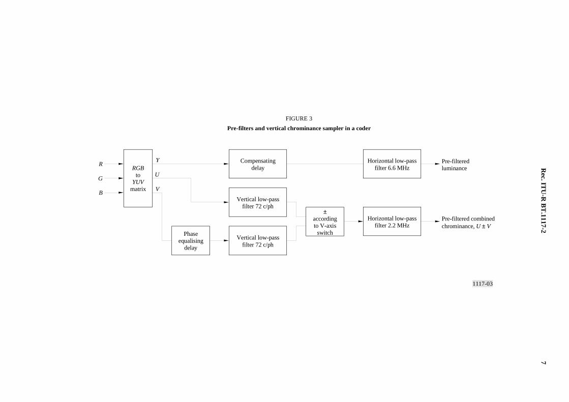
The coded signal (Fig. 1) conveys areas of the luminance and chrominance frequency spectrum shown in Fig. 2. Thesignal is formed by first processing an RGB signal to obtain band-limited luminance and chrominance signals using thearrangement shown in Fig. 3. The luminance and chrominance signals are then processed to form the coded signal usingthe arrangement shown in Fig. 4; this incorporates a Weston PAL assembler that forms the PAL-like part of the signal,together with additional circuitry concerned with the high-frequency luminance signal. In a decoder, the signal isseparated into sampled luminance and chrominance by the circuitry shown in Fig. 5. These signals are then post-filteredand converted back to RGB as shown in Fig. 6.
1117-01
0( fsc) (3fsc /2) (– 6 dB)
Luminance Additional luminance
Chrominance
4.43 5.5 6.65 9.5 MHz
FIGURE 1
Spectrum of Com3 signal
FIGURE 1/BT.1117-2...[D01] = 3 CM

6 Rec. ITU-R BT.1117-2
1117-02
288
216
144
72
0
0 3fsc /2
0
72
0
fsc /2
fsc
0 5 MHz
fsc
FIGURE 2
The two-dimensional spectra of the luminance and chrominance signals that may beconveyed by the coded signal, drawn for a 16:9 aspect ratio
Limit of resolution for a Kell factor of 0.65
Low-frequency luminance
Horizontal frequency
ChrominanceSpectrum transmissible using a bandwidth of 5.5 MHz
Additional spectrum transmissible using full-bandwidth
Corresponding frequency in the coded signal, showing direction of increasing frequency
Ver
tica
l fre
quen
cy (
c/ph
)
High-frequencyluminance
(4.4 MHz) (6.6 MHz)
(2.2 MHz)
8.2 8.8 6.6 MHz
4.4 6.6 MHz
c/ph: cycles/active picture height
FIGURE 2/BT.1117-2...[D01] = 3 CM
Rec. IT
U-R
BT
.1117-27
1117-03
Y
U
V
R
G
B
FIGURE 3
Pre-filters and vertical chrominance sampler in a coder
Compensatingdelay
Vertical low-passfilter 72 c/ph
Vertical low-passfilter 72 c/ph
Horizontal low-passfilter 6.6 MHz
Horizontal low-passfilter 2.2 MHz
RGBto
YUVmatrix
Phaseequalising
delay
±accordingto V-axis
switch
Pre-filteredluminance
Pre-filtered combinedchrominance, U ± V
FIGU
RE
3/BT
.1117-2...[D03] =
3 CM

8R
ec. ITU
-R B
T.1117-2
1117-04
FIGURE 4
Block diagram of circuitry for forming a coded signal from thepre-filtered luminance and combined chrominance signals
Pre-filteredluminance
Pre-filteredcombinedchrominance U ± V
Analoguecodedsignal
Compensatingdelay
Add syncsand burst
Digital/analogue
converter andpost-filter
Filter F1
Filter F2
Low-passsub-bandsynthesis
filter
High-passsub-bandsynthesis
filter
High-passsub-bandanalysis
filter
Low-passsub-bandanalysis
filter
Luminancesub-band splitter
Chrominance/high-frequencyluminance combiner
Weston PAL assembler
Digitalcodedsignal
(4 fsc)
Sample at fsc
Modulate at fsc
Sample at2 fsc
Sample at fsc
FIGU
RE
4/BT
.1117-2...[D04] =
3 CM

Rec. IT
U-R
BT
.1117-29
1117-05
FIGURE 5
Block diagram of circuitry for splitting the coded signal intosampled luminance and combined chrominance signals
Low-passsub-bandsynthesis
filter
High-passsub-bandsynthesis
filter
Low-passsub-bandanalysis
filter
High-passsub-bandanalysis
filter
Compensatingdelay
Filter F4
Filter F3
Coded signal
Luminanceto post-filter
CombinedchrominanceU ± V to post-filter
Weston PAL splitter
Chrominance/high-frequencyluminance splitter
Luminance sub-bandcombiner
Sample at2 fsc
Sample at fsc
Sample at fsc
Modulate at fsc
FIGU
RE
5/BT
.1117-2...[D05] =
3 CM

10R
ec. ITU
-R B
T.1117-2
1117-06
Y
U
V
R
G
B
FIGURE 6
Post filters in a decoder
Compensatingdelay
Vertical low-passfilter 72 c/ph
Vertical low-passfilter 72 c/ph
Horizontal low-passfilter 6.6 MHz
Horizontal low-passfilter 2.2 MHz
YUVto
RGBmatrix
Phaseequalising
delay±accordingto V-axis
switch
Luminancefrom splitter
Combinedchrominancefrom splitterU ± V
FIGU
RE
6/BT
.1117-2...[D06] =
3 CM
Rec. ITU-R BT.1117-2 11
The basic format of the signal is exactly like normal PAL. Indeed, in plain areas (where only very low frequencyluminance and chrominance signals are present and there is no variation of chrominance from line-to-line), the signal isidentical to a normal PAL signal. This specification therefore does not discuss aspects such as signal levels, timing ofsync pulses or subcarrier phase.
The coded signal will be specified by defining the filter responses and sampling lattices used in Figs. 3 and 4. Theresponses of the filters of Fig. 4 are more critical than those of Fig. 3, since they determine the details of the spectrum ofFig. 1 and thus the degree to which the various parts of the coded signal may be separated from each other in a decoder.There are many sets of filters that could be used which would allow (near) perfect separation of the component signals ina decoder using a corresponding set of filters; however, it is necessary to specify one unique set of filters in order todefine precisely a signal format that can be coded and decoded using equipment produced by many manufacturers.
3 Pre- and post-filters for luminance and chrominance
A suitable template for the 6.6 MHz low-pass luminance pre-filter is given in Fig. 7. The low-pass post-filter in thedecoder (Fig. 6) may have the same response. The template shows that the filter is approximately 3 dB down at6.6 MHz (3fsc/2), the notional frequency at which the luminance signal is sampled. This allows the pre-post filterproduct to be a Nyquist filter (skew-symmetric about a gain of 0.5 at 3fsc/2), to prevent loss of quality in applications inwhich an extended studio PAL signal is to be decoded to component form and subsequently re-coded in the samesampling phase.
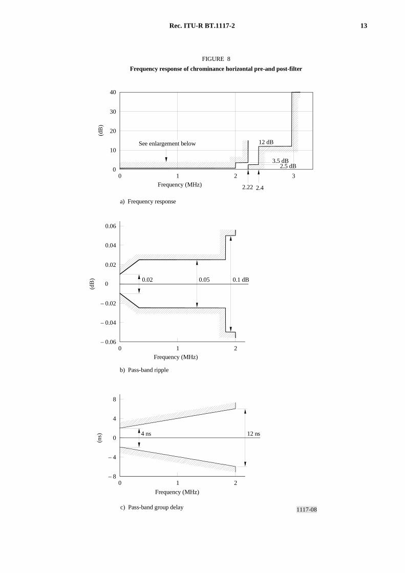
A suitable template for the 2.2 MHz low-pass chrominance pre-filter is given in Fig. 8. The low-pass post-filter in thedecoder (Fig. 6) may have the same response, although it may be preferable to include a view filter that has a moregentle roll-off, to reduce the visibility of horizontal ringing. The template shows that the filter response is approxi-mately 3 dB down at fsc/2 to allow the product of the pre- and post-filter response to be Nyquist, as discussed above forthe luminance.
The chrominance vertical pre- and post-filters should have unity gain at 0 c/ph, a notional cut-off point at 72 c/ph, andshould have a null at 144 c/ph (c/ph is used as an abbreviation for cycles per active picture height, so for example,144 c/ph is the highest vertical frequency that may be represented in a single field). A template for these filters is notgiven, since the detailed response achievable in practice will be determined by the chosen implementation. The filtershould have a group delay of an odd number of half-lines; this is necessary to ensure that chrominance and luminancemay be vertically co-timed at the coder output.
A “combined chrominance” signal is formed from the vertically-filtered chrominance signals, consisting of U + V andU – V on alternate lines, determined by the polarity of the V-axis switch.
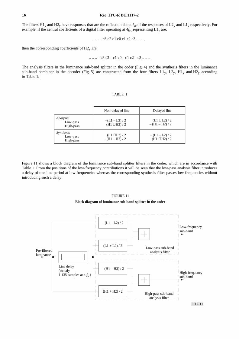
4 Luminance sub-band splitter filters
The filters used to split the luminance signal into low-frequency and high-frequency parts in the coder and to recombinethese parts in the decoder are two-dimensional sub-band analysis and synthesis filters. Each filter has a vertical apertureof two lines.
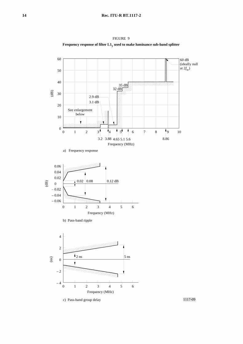
The filters can be expressed in terms of four one-dimensional filters: L1y, L2y, H1y and H2y.
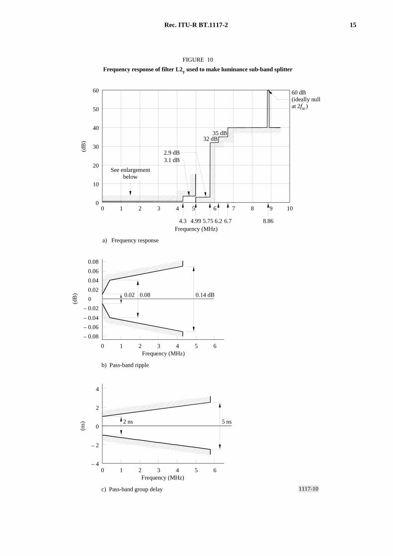
Templates for the filters L1y and L2y are shown in Figs. 9 and 10. Group delay templates are included largely forcompleteness; it is expected that these filters would be implemented as symmetrical digital FIR filters and would thushave exactly zero group delay. In order to ensure the minimum degradation of the luminance signal by a codec,L1y should be such that L1y
2 is antisymmetric about a response of 1/2 at 0.875fsc. Similarly, L2y should be suchthat L2y
2 is antisymmetric about a response of 1/2 at 1.125fsc.

12 Rec. ITU-R BT.1117-2
1117-07
0
0 1 2 3 4 5 6
12 dB
0
10
20
30
40
7654321 8 9 100
2 ns 6 ns
0 1 2 3 4 5 6
0
2
4
– 2
– 4
3.5 dB2.5 dB
6.65 7.2 8.9
FIGURE 7
Frequency response of luminance pre-and post-filter
(dB
)(n
s)
a) Frequency response
See enlargement below
b) Pass-band ripple
c) Pass-band group delay
Frequency (MHz)
Frequency (MHz)
Frequency (MHz)
(dB
) 0.02 0.05 0.1 dB
– 0.06
– 0.04
– 0.02
0.02
0.04
0.06
FIGURE 7/BT.1117-2...[D07] = 3 CM
Rec. ITU-R BT.1117-2 13
1117-08
12 dB
0
10
20
30
40
21 30
0
0 1 2
4 ns 12 ns
0 1 2
0
4
8
– 4
– 8
FIGURE 8
Frequency response of chrominance horizontal pre-and post-filter
(dB
)(n
s)
a) Frequency response
See enlargement below
b) Pass-band ripple
c) Pass-band group delay
Frequency (MHz)
Frequency (MHz)
Frequency (MHz)
3.5 dB2.5 dB
2.22 2.4
(dB
)
– 0.06
– 0.04
– 0.02
0.02
0.04
0.06
0.02 0.05 0.1 dB
FIGURE 8/BT.1117-2...[D08] = 3 CM
14 Rec. ITU-R BT.1117-2
1117-09
0
0 1 2 3 4 5 6
2 ns 5 ns
0 1 2 3 4 5 6
0
2
4
– 2
– 4
32 dB35 dB
0
10
20
30
40
50
60
7654321 8 9 100
(dB
)(n
s)
a) Frequency response
See enlargement below
b) Pass-band ripple
c) Pass-band group delay
Frequency (MHz)
Frequency (MHz)
Frequency (MHz)
3.2 5.1 8.863.88 4.65 5.6
3.1 dB
2.9 dB
(dB
)
– 0.06
– 0.04
– 0.02
0.02
0.04
0.06
0.02 0.08 0.12 dB
60 dB (ideally null at 2fsc)
FIGURE 9
Frequency response of filter L1y used to make luminance sub-band splitter
FIGURE 9/BT.1117-2...[D09] = 3 CM
Rec. ITU-R BT.1117-2 15
1117-10
0
0 1 2 3 4 5 6
32 dB35 dB
0
10
20
30
40
50
60
7654321 8 9 100
0 1 2 3 4 5 6
0
2
4
– 2
– 4
2 ns 5 ns
(dB
)(n
s)
a) Frequency response
See enlargementbelow
b) Pass-band ripple
c) Pass-band group delay
Frequency (MHz)
Frequency (MHz)
4.3 6.2 8.864.99 5.75 6.7
3.1 dB2.9 dB
FIGURE 10
Frequency response of filter L2y used to make luminance sub-band splitter(d
B)
Frequency (MHz)
– 0.06
– 0.04
– 0.02
0.02
0.04
0.06
– 0.08
0.08
0.02 0.08 0.14 dB
60 dB (ideally null at 2fsc)
FIGURE 10/BT.1117-2...[D10] = 3 CM
16 Rec. ITU-R BT.1117-2
The filters H1y and H2y have responses that are the reflection about fsc of the responses of L2y and L1y respectively. Forexample, if the central coefficients of a digital filter operating at 4fsc representing L1y are:
.. .. .. c3 c2 c1 c0 c1 c2 c3 .. .. ..,
then the corresponding coefficients of H2y are:
.. .. .. – c3 c2 – c1 c0 – c1 c2 – c3 .. .. ..
The analysis filters in the luminance sub-band splitter in the coder (Fig. 4) and the synthesis filters in the luminancesub-band combiner in the decoder (Fig. 5) are constructed from the four filters L1y, L2y, H1y and H2y accordingto Table 1.
TABLE 1
Figure 11 shows a block diagram of the luminance sub-band splitter filters in the coder, which are in accordance withTable 1. From the positions of the low-frequency contributions it will be seen that the low-pass analysis filter introducesa delay of one line period at low frequencies whereas the corresponding synthesis filter passes low frequencies withoutintroducing such a delay.
1117-11
– (L1 – L2) / 2
(L1 + L2) / 2
– (H1 – H2) / 2
(H1 + H2) / 2
FIGURE 11
Block diagram of luminance sub-band splitter in the coder
Pre-filteredluminance
Low-pass sub-bandanalysis filter
High-pass sub-bandanalysis filter
Low-frequencysub-band
High-frequencysub-band
Line delay(strictly1 135 samples at 4 fsc)
FIGURE 11/BT.1117-2...[D11] = 3 CM
Non-delayed line Delayed line
AnalysisLow-passHigh-pass
– (L1 – L2) / 2(H1 + H2) / 2
(L1 + L2) / 2– (H1 – H2) / 2
SynthesisLow-passHigh-pass
(L1 + L2) / 2– (H1 – H2) / 2
– (L1 – L2) / 2(H1 + H2) / 2
Rec. ITU-R BT.1117-2 17
5 Sub-band filters for combining chrominance and high-frequency luminance
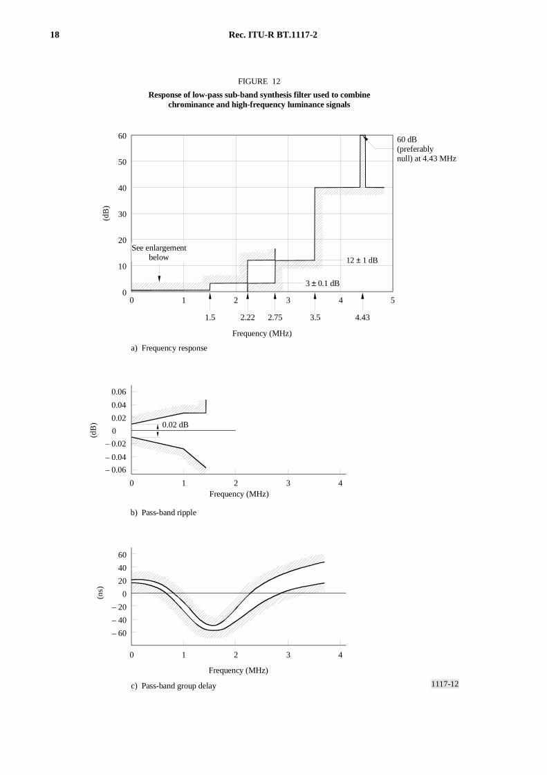
These filters are one-dimensional sub-band synthesis filters. They determine the spectrum of the coded signal in theregion around 6.6 MHz. The low-pass synthesis filter has an amplitude response which is maximally flat at DC and fscand is –3 dB at fsc/2. It is not quite phaseless; this allows the combination of analysis and synthesis filters to give perfectreconstruction and to have a well-behaved amplitude response while having a relatively small horizontal aperture. Themaximally-flat nature of the response ensures that virtually no high-frequency luminance information travels in theregion interpreted as chrominance by a normal PAL decoder, by virtue of the high attenuation of the high-pass synthesisfilter around DC. This prevents high-frequency luminance information giving rise to cross-colour when a normal PALdecoder is used.
Figure 12 shows a template for the response of the low-pass synthesis filter which acts as a low-pass filter in the coderafter up-sampling the sampled chrominance signal from fsc to 2fsc.
The high-pass synthesis filter is derived from the low-pass synthesis filter by inverting alternate coefficients andinserting a delay of one clock cycle at 2fsc, and then reversing the order of the resulting coefficients. This relationship iswell-known in the field of sub-band analysis-synthesis.
The analysis filters used to separate chrominance and high-frequency luminance in the decoder are derived by reversingthe order of the coefficients in the corresponding synthesis filters.
The fsc-sampling operation at the input to the two synthesis filters consists of multiplying the signal by a delta functionwith a period of 1/fsc, co-phased with the colour subcarrier. If the coder is realized using circuitry clocked at 4fsc, thissampling operation reduces to forcing three samples out of four to zero.
6 Weston PAL assembler and splitter filters
These filters are specified in a similar way to the luminance sub-band analysis and synthesis filters, in terms of fourone-dimensional filters: L1w, L2w, H1w and H2w.
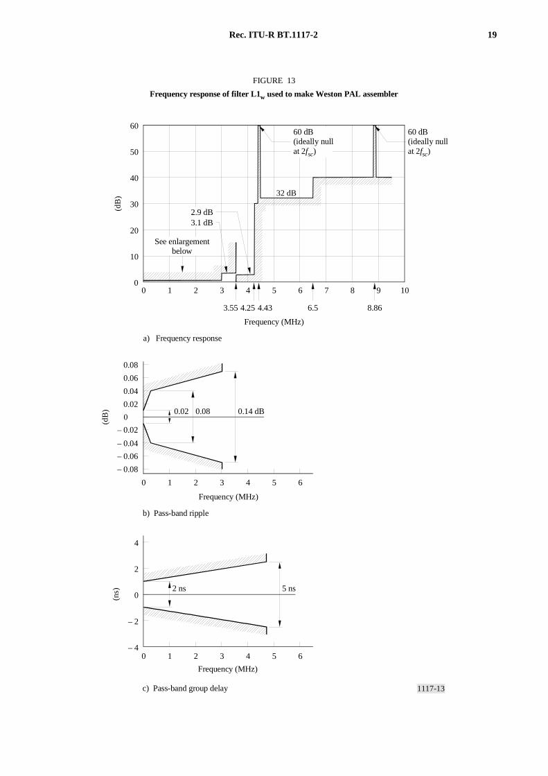
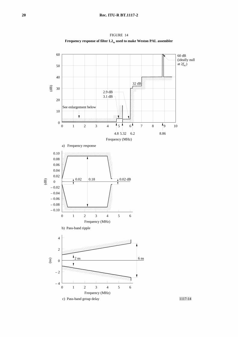
Templates for the filters L1w and L2w are shown in Figs. 13 and 14. Group delay templates are included largely forcompleteness; it is expected that these filters would be implemented as symmetrical digital FIR filters and would thushave exactly zero group delay. In order to ensure the minimum degradation of the luminance signal by a codec,L1w should be such that L1w
2 is antisymmetric about a response of 1/2 at 0.8fsc. Similarly, L2w should be such that L2w2
is antisymmetric about a response of 1/2 at 1.2fsc. Note the tight constraints on filter responses at fsc; this is to ensuregood compatibility with normal PAL.
The filters H1w and H2w are derived from L1w and L2w in exactly the manner described for the luminance sub-bandfilters.
The filters F1-F4 are constructed from these four filters according to Table 2.
TABLE 2
From the positions of the low-frequency contributions (L1 + L2) it will be seen that F3 introduces a delay of one lineperiod to low luminance frequencies whereas F1 passes low frequencies without introducing such a delay. Filters F1and F2 may be realized in a manner similar to that shown in Fig. 11.
Non-delayed line Delayed line
Assembler
F1 (low-pass)F2 (high-pass)
(L1 + L2) / 2– (H1 – H2) / 2
– (L1 – L2) / 2(H1 + H2) / 2
Splitter
F3 (low-pass)F4 (high-pass)
– (L1 – L2) / 2(H1 + H2) / 2
(L1 + L2) / 2– (H1 – H2) / 2
18 Rec. ITU-R BT.1117-2
1117-12
0 1 2 3 4
0
40
– 20
– 60
20
– 40
60
0
0 1 2 3 4
12 ± 1 dB
0
10
20
30
40
50
60
543210
FIGURE 12
Response of low-pass sub-band synthesis filter used to combine chrominance and high-frequency luminance signals
(dB
)(n
s)
a) Frequency response
See enlargement below
b) Pass-band ripple
c) Pass-band group delay
Frequency (MHz)
Frequency (MHz)
60 dB (preferably null) at 4.43 MHz
3 ± 0.1 dB
1.5 4.432.22 2.75 3.5
(dB
)
Frequency (MHz)
0.02 dB
– 0.06
– 0.04
– 0.02
0.02
0.04
0.06
FIGURE 12/BT.1117-2...[D12] = 3 CM
Rec. ITU-R BT.1117-2 19
1117-13
0
0 1 2 3 4 5 6
0 1 2 3 4 5 6
0
2
4
– 2
– 4
2 ns 5 ns
32 dB
0
10
20
30
40
50
60
7654321 8 9 100
(dB
)(n
s)
a) Frequency response
See enlargementbelow
b) Pass-band ripple
c) Pass-band group delay
Frequency (MHz)
Frequency (MHz)
Frequency (MHz)
4.43 8.863.55 4.25 6.5
3.1 dB2.9 dB
FIGURE 13
Frequency response of filter L1w used to make Weston PAL assembler(d
B)
– 0.06
– 0.04
– 0.02
0.02
0.04
0.06
– 0.08
0.08
0.02 0.08 0.14 dB
60 dB (ideally nullat 2fsc)
60 dB (ideally nullat 2fsc)
FIGURE 13/BT.1117-2...[D13] = 3 CM
20 Rec. ITU-R BT.1117-2
1117-14
0
0 1 4 62 3 5
0
4
– 4
2
– 2
0 1 4 62 3 5
2 ns 6 ns
0
10
20
30
40
50
60
643210 109875
32 dB
(ns)
a) Frequency response
See enlargement below
b) Pass-band ripple
c) Pass-band group delay
Frequency (MHz)
Frequency (MHz)
Frequency (MHz)
8.864.8 5.32 6.2
2.9 dB3.1 dB
FIGURE 14
Frequency response of filter L2w used to make Weston PAL assembler(d
B)
– 0.06
– 0.04
– 0.02
0.02
0.04
0.06
0.08
0.10
– 0.10
– 0.08
0.02 0.18 0.02 dB
(dB
)
60 dB (ideally nullat 2fsc)
FIGURE 14/BT.1117-2...[D14] = 3 CM
Rec. ITU-R BT.1117-2 21
7 Compensating delays
The delays through the luminance and chrominance paths of the coder clearly need to be equal to ensure that the codedpicture appears correctly registered on both the decoder of Figs. 5 and 6 and a normal PAL decoder.
The luminance low-pass analysis filter introduces a delay of one line period, whilst F1 does not introduce such a delay,as explained earlier. Thus the circuitry of Fig. 4 introduces a total delay of one line period to the luminance signal. Thefilter F2 acts like a vertical filter having coefficients of –½, ½ at fsc and thus introduces a delay to the chrominance signalof half a field line pitch.
Vertical alignment of luminance and chrominance can therefore be achieved by ensuring that the chrominance isvertically delayed by half a line pitch with respect to the luminance in the pre-filters of Fig. 3 and the post-filtersof Fig. 6. A compensating delay will be required in the luminance path if the vertical chrominance pre-filter has a delaygreater than half a line. Compensating delays for this purpose are shown in Figs. 3 and 6.
Correct horizontal alignment requires the addition of several delays:
– The luminance signal must be delayed by 2 samples at 4fsc and the V chrominance signal by 4 samples (bothrelative to the U signal) in the pre-filters of Fig. 3. These delays are an approximate pre-correction for thedifferential delay introduced to U and V by the phase characteristic of the PAL assembler filter F2, and for thegroup delay characteristic of the low-pass sub-band synthesis filter used to combine chrominance andhigh-frequency luminance.
– To ensure correct positioning of the main luminance signal with the high-frequency luminance signal and thechrominance, a compensating delay is required in series with the signal passing through the filter F1 in Fig. 4and F3 in Fig. 5. This delay compensates for the propagation delay through the sub-band filters used to joinluminance and chrominance, and through the adder and modulator through which the combined signal passes. Thevalue of the delay will depend on the exact design of the filters.
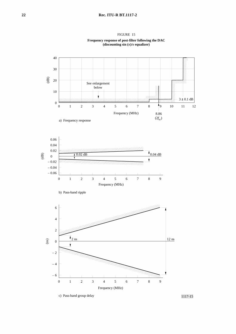
8 DAC post-filter
The frequency responses of the DAC post-filter at the output of the coder and the ADC pre-filter at the input to adecoder are chosen to have a product that is approximately Nyquist. The ideal response of the post-filter is shown inFig. 15. The post-filter will of course include a sin (x)/x equalizer, whose response is not included in the figure. Eachfilter, excluding the sin (x)/x equalizer, is designed to be square-root Nyquist, and is 3 dB down at 2fsc. The ADCpre-filter in the decoder may have the same response.
Although the filter would normally be implemented as analogue circuitry, they may alternatively be implementeddigitally by over-sampling the signal and using a DAC and ADC operating at a higher frequency. This will make itpossible to achieve a pre-post product that is much closer to Nyquist, without problems associated with non-uniformgroup delay associated with analogue filters.
22 Rec. ITU-R BT.1117-2
1117-15
0
0 1 4 62 3 5 7 98
643210 109875 12110
10
20
30
40
0
4
– 4
2
– 2
6
– 6
0 1 4 62 3 5 7 98
2 ns 12 ns
(2fsc)
FIGURE 15
Frequency response of post-filter following the DAC(discounting sin (x)/x equalizer)
(dB
)(n
s)
See enlargement below
b) Pass-band ripple
c) Pass-band group delay
Frequency (MHz)
Frequency (MHz)
Frequency (MHz)
a) Frequency response
3 ± 0.1 dB
8.86
– 0.06
– 0.04
– 0.02
0.02
0.04
0.06
0.02 dB 0.04 dB
(dB
)
FIGURE 15/BT.1117-2...[D15] = 3 CM
Rec. ITU-R BT.1117-2 23
APPENDIX 1
TO ANNEX 2
A European Broadcasting Union (EBU)evaluation of the Com3 system
1 Introduction
Future broadcast distribution systems featuring improved quality and wide aspect ratio, such as digital, MAC andPALplus require source signals of “component” quality. The signal quality normally produced by composite equipment,although satisfactory for conventional delivery media, will not be good enough for the improved systems. Rapidintroduction of new systems will, therefore, require an unacceptable level of capital investment by some broadcasterswho have a large composite programme production infrastructure.
The composite compatible component (Com3) system was developed by the British Broadcasting Corporation (BBC) toallow near component picture quality to be achieved over a wideband or digital composite infrastructure, as may beappropriate for a number of broadcasters. In this manner the capital investment burden will be reduced making asuccessful early introduction of new systems more likely.
2 The Com3 system
The system specification makes the following claims:
– luminance resolution comparable with Recommendation ITU-R BT.601;
– isotropic chrominance resolution for 16:9 viewing;
– complete freedom from cross-colour and cross-luminance;
– coded signal is usable with the majority of composite PAL equipment;
– horizontal luminance bandwidth of 5 MHz and freedom from cross-effects are maintained after band limiting of thecoded signal to normal PAL bandwidths;
– the coded signal can be decoded by conventional PAL decoders with a just perceptible reduction in quality;
– conventionally coded PAL/NTSC can be decoded by the Com3 decoder, again with a slight improvement in quality.
Similar claims are made for NTSC although, after appropriate bandwidth limitation of the channel, the horizontalluminance bandwidth is correspondingly lower.
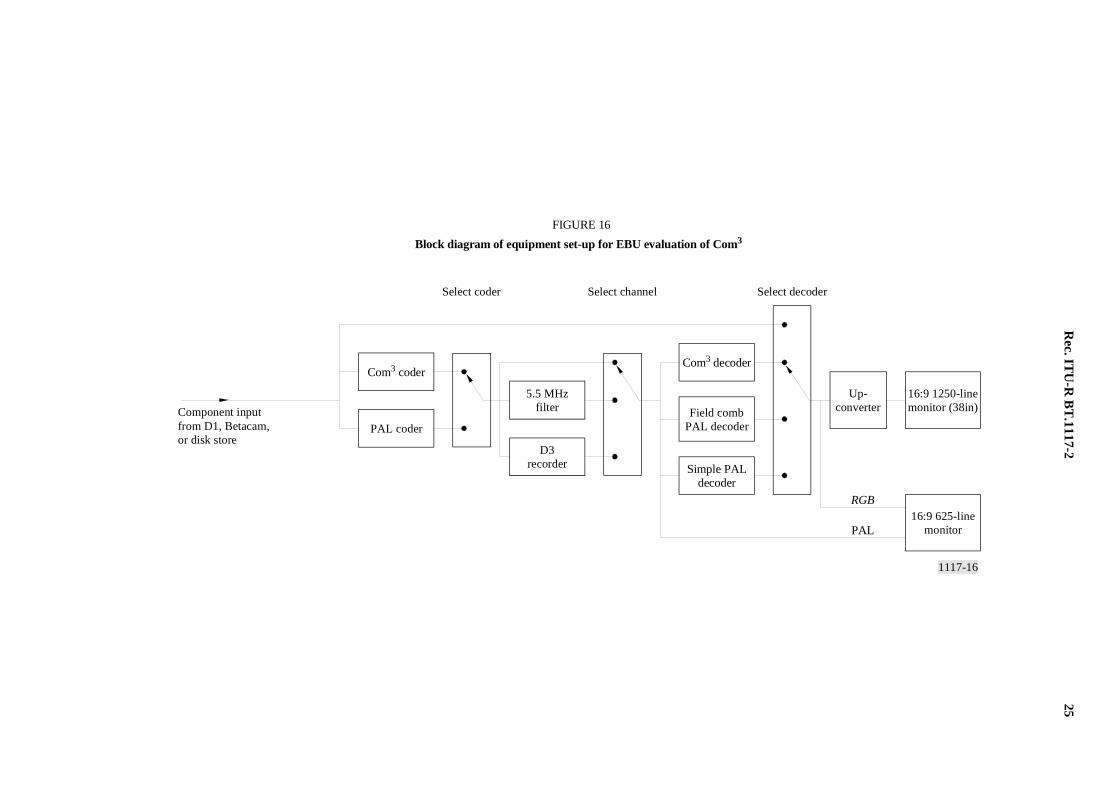
3 The experimental arrangement
The block diagram of the experimental arrangement is shown in Fig. 16.
A range of component sources was made available. These included luminance and chrominance frequency gratings, toexplore the frequency responses of the system, and 16:9 aspect ratio video excerpts stored in component form on anAbekas disk drive and from D1 and Betacam videotape recorders. Down-converted HDTV sources in D1 format werealso made available to provide high quality moving scenes. The members of the Expert Group were also invited to bringtest material of their choice.
Means were provided for comparing the following coding paths:
– Com3 encode – Com3 decode,
– Conventional PAL encode – Conventional PAL decode,
– Com3 encode – conventional PAL decode,
24 Rec. ITU-R BT.1117-2
– Conventional PAL encode – Com3 decode,
– Com3 encode – field delay PAL decode,
– Conventional Pal encode – field delay decode.
The behaviour of Com3 and PAL for limited bandwidth channels could be investigated by passing the signal througheither a 5.5 MHz low-pass filter, a D3 recorder with standard filters or a remote VPR6 C format recorder. Two D3videotape recorders were provided for recording and replay of Com3 signals, one with standard input and output filtersand one with modified filters (approximately half-Nyquist at 8.8 MHz – twice the PAL sub-carrier frequency).
Both 625-line and HDTV displays were provided. The 625-line display was an EV 1629 professional monitor and theHDTV display was a 38 in. SONY HDM 3830E fed by a Snell & Wilcox HD5100 up-converter. This arrangementallowed viewing of the source, the compatible picture and the decoded picture and the use of the SONY HDTV displayensured that the display tube was not a limiting factor.
3.1 Test sequences
The following test sequences were used in the evaluation along with a selection of longer natural sequences
3.1.1 Newpat
A highly critical test pattern which contains three different test signals:
– A two-dimensional luminance frequency sweep or zone-plate in which horizontal frequency increases vertically andvertical frequency increases horizontally. This part of the pattern allows luminance frequency response to beanalysed and clearly reveals any alias patterns or spurious signal components such as cross-colour.
– Zone plates for the U and V chrominance components, holding the luminance constant; these again reveal aliasingand cross-luminance.
– A matrix of coloured squares which exercises every transition between the three primary and three complementarycolours, black and white; this part of the pattern allows analysis of transient response and the level of U/Vcross-talk.
3.1.2 Noël
A moving 16:9 sequence, originated in HDTV and down-converted to Recommendation ITU-R BT.601. This is a longexcerpt from a light entertainment programme and contains several areas of highly detailed saturated colours. It wasused for assessing subjective chrominance resolution and for detecting colour coding artefacts such as cross-luminance.
3.1.3 Cross-colour sequence
This is a moving sequence comprising a collection of patterned fabrics, chosen to excite both coarse and finecross-colour, and some plain coloured fabrics which reveal the presence of cross-luminance. The camera pans andzooms over the scene.
3.1.4 Wimbledon
This is a palindromic sequence of a pan across a crowd of spectators at Wimbledon, and was originated at HDTV. Aswell as a high level of luminance detail, it contains numerous coloured areas, of varying size, hue and saturation, andchrominance transitions (in the spectator’s clothes). It was used for assessing luminance aliasing, small and large areacross-luminance, and chrominance bandwidth.
3.1.5 Gate
This is pan and zoom across a large and highly detailed, gilded wrought iron gate. It was used for assessing cross-effectsand luminance aliasing.
Rec. IT
U-R
BT
.1117-225
1117-16
RGB
PAL
FIGURE 16
Block diagram of equipment set-up for EBU evaluation of Com3
Com3 coder
5.5 MHzfilter
Up-converterField comb
PAL decoder
Simple PALdecoder
Com3 decoder
PAL coder
D3recorder
16:9 1250-linemonitor (38in)
16:9 625-linemonitor
Component inputfrom D1, Betacam,or disk store
Select coder Select channel Select decoder
FIGU
RE
16/BT
.1117-2...[D16] =
3 CM

26 Rec. ITU-R BT.1117-2
4 The specialist evaluation
4.1 Behaviour of Com3 with a flat channel (greater than 9 MHz)
4.1.1 Static luminance and chrominance resolution
Using the Newpat sequence the group concluded that the luminance bandwidth of the decoded Com3 signal wascomparable to that of the component source. There was, however, a barely perceptible moving high frequency aliasappearing in the very high horizontal frequencies. This was later found not to be visible in natural pictures.
4.1.2 Chrominance resolution
Static chrominance resolution was assessed using the U and V zone-plate sections of the Newpat test pattern. Thehorizontal resolution of the decoded Com3 signal, at 2.4 MHz was slightly lower than that of Recommen-dation ITU-R BT.601. It was observed that the vertical and horizontal resolutions of Com3 were approximately equal.This means that the vertical resolution of Com3 is approximately half that of Recommendation ITU-R BT.601.
This loss of chrominance resolution relative to Recommendation ITU-R BT.601 was also observed on critical naturalpictures, e.g. Wimbledon.
Some ringing was observed on horizontal and vertical transitions of the coloured squares of the Newpat sequence butwas not observed on natural pictures.
A comparison was also made between Com3 and 4:2:0 processing. The two were found to be indistinguishable.
There was no perceptible cross-colour or cross-luminance.
4.1.3 Dynamic luminance and chrominance resolution
The dynamic luminance and chrominance resolutions of the system were investigated using a moving version of theNewpat test signal. No motion artefacts or modifications of the system performance could be observed.
4.1.4 Compatibility with conventional PAL
There are two compatibilities to be assessed, the ability of conventional decoders to decode the Com3 signal and theability of the Com3 decoder to decode a conventionally PAL coded signal. These were again assessed using the Newpattest pattern and natural pictures.
4.1.5 Com3 encoding followed by conventional PAL decoding
The Newpat test pattern and natural pictures, coded by the Com3 coder were decoded by professional simple, line delayand field delay conventional PAL decoders.
Compared to PAL encoding-PAL decoding, there was a reduction in coarse cross-colour, similar levels ofcross-luminance, a loss of vertical chrominance resolution and a slight horizontal chrominance mis-registration.
Overall, there was a barely perceptible loss of quality on natural pictures.
4.1.6 Conventional PAL coding followed by Com3 decoding
The Newpat test pattern and natural pictures, coded by the conventional PAL encoder were viewed after decoding by theCom3 decoder.
Compared to PAL encoding-PAL decoding, there was less large area cross-luminance. Edge cross-luminance wastransferred from horizontal edges (as in normal colour bars) to vertical edges (as in horizontal colour bars). Thisbehaviour is similar to that found with non-adaptive line or field comb PAL decoders. There was also an increase incoarse cross-colour.
On natural pictures, when cross-colour is not dominant, the overall picture quality was improved.
Rec. ITU-R BT.1117-2 27
4.2 Behaviour of Com3 with a non-flat channel
Since the Com3 system uses the channel bandwidth between 4.4 and 8.8 MHz to increase the available luminanceresolution, phase distortions over this band or reductions in channel bandwidth cause not only a reduction in availableluminance bandwidth but also addition artefacts such as luminance aliasing and cross-effects. The visibility of theseartefacts depends upon the magnitude of amplitude and phase distortions in the channel.
4.3 Behaviour of Com3 with a 5.5 MHz channel bandwidth
A bandwidth limitation of 5.5 MHz was chosen as this is typical of internal limitations of some analogue and digitalprocessing equipments. It also represents the nominal limit of many link systems.
With this filter in the channel, luminance resolution loss, luminance aliasing and cross-luminance were clearly visible inthe Newpat test pattern. Luminance resolution loss, luminance aliasing and edge cross-luminance were visible on naturalpictures.
The picture quality of Com3 with a 5.5 MHz channel bandwidth is therefore less than Recommendation ITU-R BT.601but remains better than PAL.
4.4 Behaviour of Com3 with an intermediate channel bandwidth
A standard D3 recorder is supplied with an input filter of approximately 6 MHz bandwidth and an output filter with aslightly wider roll-off, which functions primarily as an anti-alias filter. In order to maintain sufficient bandwidth forCom3 when using analogue inter-connection to and from the videotape machine it is necessary to install modified filters.These should each, ideally, have a half Nyquist response at twice sub-carrier frequency (~8.8 MHz). An analogue filter,however, can at best provide an approximation to this response.
With the modified filters installed, there was a just perceptible, low-level, luminance alias.
With the standard filters, the result was marginally better than for the 5.5 MHz bandwidth limitation.
4.5 Behaviour of Com3 with phase distortions in the channel
Two types of phase distortion were investigated, a fixed phase error between the chrominance sub-carrier and the burst,such as might occur through mis-alignment of a mixer, and phase distortion over the critical 4.4 to 8.8 MHz band, suchas might occur in a poorly aligned delay line or Proc-amp.
Cross-effects and luminance aliasing were just perceptible on the Newpat test sequence for a burst phase error of 5° ofsub-carrier and became slightly annoying at 15°.
Cross-effects and luminance aliasing were just perceptible for a phase error of 25 ns between 4.4 and 8.8 MHz andclearly visible for a phase error of 60 ns.
Com3 is therefore less tolerant to phase distortions than conventional PAL with delay line decoding. Phase distortionsproduce perceptible cross-effects and luminance aliasing for Com3 where PAL would produce Hannover bars for simpledecoding and saturation loss for delay line decoding.
4.6 Behaviour of Com3 for multi-generation recording
The most significant effect of multi-generation recording occurs when the Com3 signal is converted to Recommend-ation ITU-R BT.601 between generations. Under these conditions the reduction of vertical chrominance resolution is thedominant effect and increases with the number of generations as would be expected with repeated conversionsbetween 4:2:2 and 4:2:0 coding.

28 Rec. ITU-R BT.1117-2
The consequences of channel distortions arising from analogue inter-connection filters have been described and thesewould again be expected to be cumulative. A videotape of multiple generation recording with decoding to Recom-mendation ITU-R BT.601 between generations, and a known burst phase error of 1° per generation, was available.Two generations gave slight luminance aliasing and six generations gave rise to a low-level of cross-colour.
4.7 Mixing of Com3 and conventional PAL
Mixing of Com3 signals and PAL signals was demonstrated by showing a videotape of a Com3 foreground keyed into aCom3 background with an internally generated (conventional PAL) coloured border. The appearance of the colouredborder was as expected from the assessment of Com3 coding followed by PAL decoding.
5 Conclusions
For the flat channel, the claims made for the Com3 system are met.
As the channel departs from the ideal, impairments are introduced and Com3 was felt to be more critical than PAL in thisrespect.
ANNEX 3
1 Introduction
The present Recommendation contains two digital and two analogue approaches to the production of source material for16:9 625-line enhanced television.
Guidance on the distance between these approaches is of value to organisations wishing to adopt enhanced programmeproduction. This Annex briefly reviews the concepts for wide-screen production to clarify where and when each optionmight be used.
2 Wide-screen production concepts
Before discussing options for the studio video signal format it is necessary to understand the nature of 16:9 studioproduction.
2.1 Aspect ratio
The first concept concerns the basic difference between the 4:3 and 16:9 aspect ratios. The sole factor determining thisdifference is the spatial opto-electronic conversion in the source device (electronic camera, film camera, telecine) and thereverse electronic-opto spatial conversion in the display device (picture monitor, receiver). Aspect ratio is controlled bythe shape of the source sensor and the shape of the display device. The intermediate video signal for the two aspectratios is similar, and most importantly both signals use the full 576 frame lines for the active picture.

Rec. ITU-R BT.1117-2 29
The difference between the two aspect ratios can be simply demonstrated by viewing a 16:9 source signal on a standard4:3 display, vertically the picture has the same height but horizontally the image appears compressed or ‘squashed’. A16:9 signal viewed in this manner is frequently referred to as ‘anamorphic’. The correct geometry is obtained when the16:9 signal is viewed on a 16:9 display, or using the low-cost alternative of a 4:3 display with the vertical scan reducedby a factor of 3/4 (many 4:3 monitors now have a reduced scan 16:9 mode). This latter mode should not be confusedwith the compatible ‘letter-box’ wide-screen presentation on a 4:3 display comprising a central 430 line 16:9 panel withblank lines above and below. The letter-box format is reserved for compatible 4:3 transmission (as in PALplus), and theletter-box should not feature in the wide-screen production studio.
2.2 Resolution
The second concept concerns resolution. The 16:9 picture can be regarded as an increase in width on the standard4:3 picture. Thus if cameras of each aspect ratio view the same scene and are framed for the same height, the16:9 picture will contain additional horizontal information. It follows that if the corresponding video signals conform tothe same standard 625-line timing specification, then the 16:9 signal must have enhanced analogue bandwidth orincreased digital sampling frequency if the reproduced scene detail (spatial frequency) is to be similar. Bandwidthincreases from 5(5.5) MHz to 6.67(7.33) MHz and the digital luminance sampling frequency from 13.5 MHz to 18 MHz.There are circumstances when enhanced resolution by increase of bandwidth is not justified, in particular whenwide-screen transmission systems limit bandwidth to the current 5(5.5) MHz (MAC and PALplus). However for futuretransmission systems, possibly including up-conversion to HDTV, archived programme production with enhancedresolution will be advantageous. Similarly if 4:3 versions of standard specification are to be extracted as a sub-setfrom 16:9, the wide-screen original should have enhanced resolution.
2.3 Studio standard – component or composite
Current and projected future wide-screen transmission systems require a component input to the encoders, and thus theideal production format is digital component. Many installed production environments are based on composite PAL,however this does not necessarily bar wide-screen production. Replacement of all standard PAL encoders and decoderswith Clean PAL equivalents could allow use of existing PAL equipments while affording a final decode back tocomponents with negligible levels of coding artefacts. The economics of this solution may not be warranted for studioproduction, and are probably best reserved for studio and inter-studio (network) communications. Standard PAL orwide-screen encoded transmission formats should not be used for wide-screen studio production.
2.4 Studio equipment
With similar video signal specifications for 4:3 and 16:9 aspect ratios, it would appear that much existing studioequipments can be used for wide-screen production. Assuming that final transmission will be band-limited, then therequirement for enhanced resolution could be disregarded, and existing equipments can be utilised. Inevitably new ormodified cameras and picture monitors are required, and any equipments having spatial functions will requiremodification. For example, mixer wipe patterns will require geometry modification for 16:9 (an unmodified 4:3 circularpattern will appear elliptical for 16:9). Equipments with no spatial processing will not normally require modification, forexample, distribution amplifiers, routing matrices, and several formats of video tape recorder.
3 Video signal format
Following the above review of wide-screen production concepts, the where and when for each of the option video signalformats should be clear.
3.1 Digital systems
It is envisaged that the digital systems under discussion are the digital component standards of Recommen-dation ITU-R BT.601.
30 Rec. ITU-R BT.1117-2
3.1.1 Recommendation ITU-R BT.601 (Part A), 13.5 MHz luminance sampling
The digital component standard with a luminance sampling frequency of 13.5 MHz has been the mainstay ofRecommendation ITU-R BT.601 since its conception in 1982 when aspect ratio was singular and fixed at 4:3. There isnow a high level of installed equipments and a large choice of vendors for equipments conforming to the standard.
If the requirement for production is broadcasting 16:9 using one of the current or proposed bandwidth limitedwide-screen transmission formats then Recommendation ITU-R BT.601 (Part A), 13.5 MHz is adequate for16:9 production. Conversion between aspect ratios may have limitations and archived material may have insufficientresolution for use in future enhanced or high definition systems.
Existing installations will require modifications to handle the spatial differences between 4:3 and 16:9. The mostsignificant changes are included in § 1.2 of Annex 1.
Equipments masquerading as component but operating with a core composite process with integral coding interfacesshould not be used.
For new installations, equipments operating at both 13.5 MHz and higher sampling rates should be considered if futureupgrades for enhanced resolution are required.
3.1.2 Recommendation ITU-R BT.601 (Part B), 18 MHz luminance sampling
Recommendation ITU-R BT.601 now contains a Part B fully specifying the enhanced studio digital standard using18 MHz luminance sampling frequency for wide-screen 16:9 studio production. This then is the second option for adigital video signal format. Studio equipments are available for this standard, albeit the choice is limited at the presenttime, however it is possible to facilitate a complete studio installation. The newer 16:9 cameras have sufficient CCDpixel resolution for 18 MHz sampling.
The output from a 16:9 studio using 18 MHz sampling can be data-rate converted to interface with existing wide-screentransmission codecs. The source material can be archived at the higher rates and is thus future-proofed for extended andhigh definition applications. Standard 4:3 aspect ratio signals extracted from 16:9 originals will have the fullspecification of Recommendation ITU-R BT.601 (Part A), 13.5 MHz.
3.2 Analogue systems
It is of course perfectly feasible to use analogue component systems for wide-screen production provided that they arecapable of providing a bandwidth at least equal to that of the transmission system and preferably greater. This will allowbroadcasters to use such installations until such time as conversion to digital components is made.
Some broadcasters may wish to use existing analogue (or digital) composite PAL installations for wide-screenproduction as an interim measure before they can convert their facilities to digital component. This option is nowfeasible by reason of the development of Clean PAL systems which provide a composite signal compatible with existingstandard PAL equipments yet can be decoded to recover a component signal with negligible coding artefacts. Allexisting PAL encoders and decoders within the main signal processing chain will be replaced by equivalent Clean PALencoders and decoders. This includes those equipments which masquerade as composite but have a component core withintegral interface decoders and encoders. Picture monitors with integral standard PAL decoders can be used with theexception of those required for quality monitoring. The cost of Clean PAL encoders and decoders is higher than that ofstandard PAL units and the economics of this solution must be examined carefully.
A more cost effective application of Clean PAL systems is for contribution and distribution of component quality signalsover existing standard PAL communications or networks. The cost of the few codecs involved may compare favourablywith the high cost of network replacement for digital component operation.
Currently two forms of Clean PAL system have been included as suitable for the above applications.
Rec. ITU-R BT.1117-2 31
3.2.1 Com3
This option if fully specified in Annex 2. The Com3 Clean PAL system exploits the extended 8 MHz bandwidthprovided by 4fsc sampled D2 and D3 digital composite tape recorders. Using novel colour coding together with extended9 MHz bandwidth Com3 can provide a luminance bandwidth of 6.6 MHz for 16:9 production which is equivalent toabout 5 MHz in conventional 4:3. A 9 MHz bandwidth can generally be maintained within a PAL studio environmentfor which Com3 is well suited. For communication routes where links may be limited to 5 (5.5) MHz, the luminance andchrominance bandwidth of Com3 is reduced, although the system remains free of cross-effects. Com3 is a 4:2:0 systemimplying line-alternate colour difference signals, however, within a 9 MHz communication bandwidth, Com3 has nearRecommendation ITU-R BT.601 (Part A), 13.5 MHz component performance.
3.2.2 MACP
The second Clean PAL option is MACP which is the improved colour coding systems used for PALplus transmissions.The significant difference between Com3 and MACP is that encoded MACP can be conveyed within the 5 (5.5) MHz ofa standard PAL communication channel. It can therefore be used for both studio production and for communications.MACP has been described in Recommendation ITU-R BT.1197 – “Enhanced wide-screen PAL TV transmission system(the PALplus system)” – as part of the PALplus specification. MACP is a 4:1:1 system implying reduced colourdifference bandwidth and there is a small loss of high frequency diagonal resolution for stationary areas, reducing to3 MHz luminance in moving areas. Subjective tests have shown MACP to have near Recommendation ITU-R BT.601(Part A), 13.5 MHz component quality. A variant of MACP could provide an enhanced luminance bandwidth with acorrespondingly wider communication channel.