
Manual | EN - CX8093 - download - Beckhoff
75
AS2000 Blindtext Blindtext Blindtext Manual | EN CX8093 Embedded PC with PROFINET 11/10/2021 | Version: 1.6
-
Upload
khangminh22 -
Category
Documents
-
view
0 -
download
0
Transcript of Manual | EN - CX8093 - download - Beckhoff

AS2000
Blindtext Blindtext Blindtext
Manual | EN
CX8093Embedded PC with PROFINET
11/10/2021 | Version: 1.6


Table of contents
CX8093 3Version: 1.6
Table of contents1 Notes on the documentation .................................................................................................................... 5
1.1 Representation and structure of warnings......................................................................................... 61.2 Documentation issue status .............................................................................................................. 7
2 For your safety........................................................................................................................................... 82.1 Intended use...................................................................................................................................... 82.2 Staff qualification ............................................................................................................................... 82.3 Safety instructions ............................................................................................................................. 92.4 Notes on information security .......................................................................................................... 10
3 Transport and storage............................................................................................................................. 11
4 Product overview..................................................................................................................................... 124.1 CX80xx - System overview.............................................................................................................. 124.2 CX8093 - Introduction...................................................................................................................... 144.3 Technical data ................................................................................................................................. 154.4 Technical data – Profinet ................................................................................................................. 164.5 CX80xx - MicroSD cards ................................................................................................................. 17
5 Mounting and wiring................................................................................................................................ 185.1 Mounting.......................................................................................................................................... 18
5.1.1 Dimensions ...................................................................................................................... 185.1.2 Installation on mounting rails ........................................................................................... 18
5.2 Wiring............................................................................................................................................... 215.2.1 Power supply ................................................................................................................... 215.2.2 Ethernet ........................................................................................................................... 23
5.3 Changing the battery ....................................................................................................................... 25
6 Parameterizing and commissioning ...................................................................................................... 266.1 DIP switch........................................................................................................................................ 266.2 Setting the IP address ..................................................................................................................... 28
6.2.1 IP addresses.................................................................................................................... 286.2.2 Setting the address via DHCP server .............................................................................. 286.2.3 Subnet mask.................................................................................................................... 29
6.3 Configuration ................................................................................................................................... 306.3.1 CCAT adaptor.................................................................................................................. 306.3.2 CX80xx - Operating system............................................................................................. 316.3.3 Power supply terminal ..................................................................................................... 336.3.4 Web Services................................................................................................................... 356.3.5 Real Time Clock (RTC).................................................................................................... 376.3.6 1-second UPS (Uninterruptible Power Supply)................................................................ 386.3.7 CPU load ......................................................................................................................... 39
6.4 PROFINET....................................................................................................................................... 406.4.1 Adapter ............................................................................................................................ 406.4.2 Interface........................................................................................................................... 406.4.3 SyncTask ......................................................................................................................... 426.4.4 Process data.................................................................................................................... 436.4.5 Virtual Device Interface.................................................................................................... 46

Table of contents
CX80934 Version: 1.6
7 Programming ........................................................................................................................................... 497.1 Library for CX80xx........................................................................................................................... 497.2 Seconds UPS .................................................................................................................................. 49
7.2.1 Function blocks................................................................................................................ 497.2.2 Data types........................................................................................................................ 52
7.3 Diagnostics ...................................................................................................................................... 537.3.1 FUNCTION F_CX80xx_ADDRESS ................................................................................. 53
8 Ethernet .................................................................................................................................................... 548.1 System introduction ......................................................................................................................... 54
8.1.1 Ethernet ........................................................................................................................... 548.1.2 Topology example ........................................................................................................... 56
8.2 PROFINET....................................................................................................................................... 578.3 ADS-Communication ....................................................................................................................... 59
9 Error handling and diagosis................................................................................................................... 619.1 LED displays.................................................................................................................................... 61
10 Appendix .................................................................................................................................................. 6410.1 First steps ........................................................................................................................................ 6410.2 Image Update .................................................................................................................................. 6910.3 Certification...................................................................................................................................... 71
10.3.1 Ex..................................................................................................................................... 7110.3.2 FCC ................................................................................................................................. 7210.3.3 UL .................................................................................................................................... 72
10.4 Support and Service ........................................................................................................................ 73

Notes on the documentation
CX8093 5Version: 1.6
1 Notes on the documentationThis description is only intended for the use of trained specialists in control and automation engineering whoare familiar with applicable national standards.It is essential that the documentation and the following notes and explanations are followed when installingand commissioning the components. It is the duty of the technical personnel to use the documentation published at the respective time of eachinstallation and commissioning.
The responsible staff must ensure that the application or use of the products described satisfy all therequirements for safety, including all the relevant laws, regulations, guidelines and standards.
Disclaimer
The documentation has been prepared with care. The products described are, however, constantly underdevelopment.We reserve the right to revise and change the documentation at any time and without prior announcement.No claims for the modification of products that have already been supplied may be made on the basis of thedata, diagrams and descriptions in this documentation.
Trademarks
Beckhoff®, TwinCAT®, TwinCAT/BSD®, TC/BSD®, EtherCAT®, EtherCAT G®, EtherCAT G10®, EtherCAT P®,Safety over EtherCAT®, TwinSAFE®, XFC®, XTS® and XPlanar® are registered trademarks of and licensed byBeckhoff Automation GmbH.Other designations used in this publication may be trademarks whose use by third parties for their ownpurposes could violate the rights of the owners.
Patent Pending
The EtherCAT Technology is covered, including but not limited to the following patent applications andpatents:EP1590927, EP1789857, EP1456722, EP2137893, DE102015105702with corresponding applications or registrations in various other countries.
EtherCAT® is a registered trademark and patented technology, licensed by Beckhoff Automation GmbH,Germany
Copyright
© Beckhoff Automation GmbH & Co. KG, Germany.The reproduction, distribution and utilization of this document as well as the communication of its contents toothers without express authorization are prohibited.Offenders will be held liable for the payment of damages. All rights reserved in the event of the grant of apatent, utility model or design.

Notes on the documentation
CX80936 Version: 1.6
1.1 Representation and structure of warningsThe following warnings are used in the documentation. Read and follow the warnings.
Warnings relating to personal injury:
DANGERHazard with high risk of death or serious injury.
WARNINGHazard with medium risk of death or serious injury.
CAUTIONThere is a low-risk hazard that can result in minor injury.
Warnings relating to damage to property or the environment:
NOTEThere is a potential hazard to the environment and equipment.
Notes showing further information or tips:
This notice provides important information that will be of assistance in dealing with the product orsoftware. There is no immediate danger to product, people or environment.

Notes on the documentation
CX8093 7Version: 1.6
1.2 Documentation issue statusVersion Comment0.1 • Preliminary version (German only)1.0 • First release1.1 • Foreword updated
• Chapter 1-second UPS added• Chapter Operating System added
1.2 • Chapter CCAT adaptor reworked1.3 • Foreword reworked
• Chapter „For your safety“ added• ATEX warnings added
1.4 • Chapter “Transport and storage“ added1.5 • Chapter “FCC” added1.6 • Warnings for Ex area revised
• Chapter “IECEx” added
Image Version CX8093
Firmware DescriptionBuild 2229 • First version

For your safety
CX80938 Version: 1.6
2 For your safetyRead the chapter on safety and follow the instructions in order to protect from personal injury and damage toequipment.
Limitation of liability
All the components are supplied in particular hardware and software configurations appropriate for theapplication. Unauthorized modifications and changes to the hardware or software configuration, which gobeyond the documented options, are prohibited and nullify the liability of Beckhoff Automation GmbH & Co.KG.In addition, the following actions are excluded from the liability of Beckhoff Automation GmbH & Co. KG:
• Failure to comply with this documentation.• Improper use.• Use of untrained personnel.• Use of unauthorized replacement parts.
2.1 Intended useThe Embedded PC is designed for a working environment that meets the requirements of protection classIP20. This involves finger protection and protection against solid foreign objects up to 12.5 mm, but notprotection against water. Operation of the devices in wet and dusty environments is not permitted, unlessspecified otherwise. The specified limits for electrical and technical data must be adhered to.
Potentially explosive atmospheres
The Embedded PC is suitable only for the following potentially explosive atmospheres:
1. For Zone 2 atmospheres in which gas is present as a combustible material. Zone 2 means that an ex-plosive atmosphere does usually not occur during normal operation, or only for a short time.
2. For Zone 22 atmospheres in which dust is present as a combustible material. Zone 22 means that anexplosive atmosphere in the form of a cloud does usually not occur during normal operation, or onlyfor a short time.
The Embedded PC must be installed in a housing, which ensures protection class IP 54 for gas according toEN 60079-15. A housing with protection class IP 54 is required for non-conductive dust. IP 6X is required forconductive dust according to EN 60079-31.
Improper use
The Embedded PC is not suitable for operation in the following areas:
• In potentially explosive atmospheres, the Embedded PC may not be used in other zones except for2/22 and not without a suitable housing.
• Areas with an aggressive environment, e.g. aggressive gases or chemicals.• Living areas. In living areas, the relevant standards and guidelines for interference emissions must be
adhered to, and the devices must be installed in housings or control boxes with suitable attenuation ofshielding.
2.2 Staff qualificationAll operations involving Beckhoff software and hardware may only be carried out by qualified personnel withknowledge of control and automation engineering. The qualified personnel must have knowledge of theadministration of the Industrial PC and the associated network.
All interventions must be carried out with knowledge of control programming, and the qualified personnelmust be familiar with the current standards and guidelines for the automation environment.

For your safety
CX8093 9Version: 1.6
2.3 Safety instructionsThe following safety instructions must be followed during installation and working with networks and thesoftware.
Explosion protection
WARNINGRisk of explosionGases or dusts can be ignited in potentially explosive atmospheres. Read and follow the safety instructionsto prevent deflagrations or explosions.
The Embedded PC must be installed in a housing, which ensures protection class IP54 for gas according toEN 60079-15. A housing with protection class IP54 is required for non-conductive dust. IP6X is required forconductive dust according to EN 60079-31.
Observe the temperature at the cable entry points into the housing. If the temperature during nominaloperation is higher than 70 °C at the entry points or higher than 80 °C at the wire branching points, cablesmust be selected that are designed for these high temperatures and operation in potentially explosiveatmospheres.
Tighten the screws of the fieldbus connectors firmly so that the connectors do not slip out due to vibrations.Only use RJ45 connectors with an intact latching lug.
Maintain the prescribed ambient temperature during operation. The permissible ambient temperature rangeduring operation is 0 °C to +55 °C.
Take measures to prevent the rated operating voltage exceeding 119 V through short-term interferencevoltages.
Switch off the power supply and ensure that no explosive atmosphere occurs when:
• Bus Terminals are connected or removed,• the Embedded PC is wired or cables are connected,• DIP switches or ID switches are set,• the front flap is opened,• the MicroSD card or battery is replaced,• the USB port behind the front flap is used.
Mounting• Never work on live equipment. Always switch off the power supply for the device before installation,
troubleshooting or maintenance. Protect the device against unintentional switching on.• Observe the relevant accident prevention regulations for your machine (e.g. the BGV A 3, electrical
systems and equipment).• Ensure standard-compliant connection and avoid risks to personnel. Ensure that data and supply
cables are laid in a standard-compliant manner and ensure correct pin assignment.• Observe the relevant EMC guidelines for your application.• Avoid polarity reversal of the data and supply cables, as this may cause damage to the equipment.• The devices contain electronic components, which may be destroyed by electrostatic discharge when
touched. Observe the safety precautions against electrostatic discharge according to DIN EN61340-5-1/-3.
Working with networks• Restrict access to all devices to an authorized circle of persons.• Change the default passwords to reduce the risk of unauthorized access.• Protect the devices with a firewall.

For your safety
CX809310 Version: 1.6
• Apply the IT security precautions according to IEC 62443, in order to limit access to and control ofdevices and networks.
Working with the software• The sensitivity of a PC against malicious software increases with the number of installed and active
software.• Uninstall or disable unnecessary software.
Further information about the safe handling of networks and software can be found in the BeckhoffInformation System:http://infosys.beckhoff.com
Document nameIPC Security Guideline
2.4 Notes on information securityThe products of Beckhoff Automation GmbH & Co. KG (Beckhoff), insofar as they can be accessed online,are equipped with security functions that support the secure operation of plants, systems, machines andnetworks. Despite the security functions, the creation, implementation and constant updating of a holisticsecurity concept for the operation are necessary to protect the respective plant, system, machine andnetworks against cyber threats. The products sold by Beckhoff are only part of the overall security concept.The customer is responsible for preventing unauthorized access by third parties to its equipment, systems,machines and networks. The latter should be connected to the corporate network or the Internet only ifappropriate protective measures have been set up.
In addition, the recommendations from Beckhoff regarding appropriate protective measures should beobserved. Further information regarding information security and industrial security can be found in ourhttps://www.beckhoff.com/secguide.
Beckhoff products and solutions undergo continuous further development. This also applies to securityfunctions. In light of this continuous further development, Beckhoff expressly recommends that the productsare kept up to date at all times and that updates are installed for the products once they have been madeavailable. Using outdated or unsupported product versions can increase the risk of cyber threats.
To stay informed about information security for Beckhoff products, subscribe to the RSS feed at https://www.beckhoff.com/secinfo.

Transport and storage
CX8093 11Version: 1.6
3 Transport and storageTransport
NOTEShort circuit due to moistureMoisture can form during transport in cold weather or in the event of large temperature fluctuations.Avoid moisture formation (condensation) in the Embedded PC, and leave it to adjust to room temperatureslowly. If condensation has occurred, wait at least 12 hours before switching on the Embedded PC.
Despite the robust design of the unit, the components are sensitive to strong vibrations and impacts. Duringtransport the Embedded PC must be protected from
• mechanical stress and• use the original packaging.
Table 1: Weight and Dimensions.
CX80xxWeight 180 gDimensions (W x H x D) 64 mm x 100 mm x 73 mm
Storage• The battery should be removed if the Embedded PC is stored at temperatures above 60 °C. The
battery should be stored separate from the Embedded PC in a dry environment at a temperaturebetween 0 °C and 30 °C.The preset date and time are lost if the battery is removed.
• Store the Embedded PC in the original packaging.

Product overview
CX809312 Version: 1.6
4 Product overview
4.1 CX80xx - System overviewCX80xx is a device family of programmable controllers with 32-bit ARM-based CPU, which can be used forprocessing of PLC programs or as slave devices for higher-level fieldbus systems. Unlike with the non-programmable EtherCAT couplers of the EK series, which only act as gateway between the associatedfieldbus system and the connected EtherCAT terminals, the CX80xx is programmable and able to run itsown control program.
The devices from the CX80xx series represent a further development of the well-known and proven 16-bitmicrocontroller-based Bus Terminal Controllers from the BC and BX series including more efficient 32-bitprocessors. As with the BC/BX, it is also ensured in the case of the CX80xx that the control and the localprogram continue to be executed in the case of interruption of the higher-level fieldbus system. The CX80xxdevices can therefore be used as local controllers. Alternatively, Bus Terminals (K-bus) or EtherCATTerminals (E-bus) can be connected; the CX80xx automatically recognizes which terminal system isconnected during the start-up phase. The use of EtherCAT gives rise to further options, such as therealization of different topologies, the integration of further bus systems such as CANopen, PROFIBUS andPROFINET and – with the EtherCAT Box Modules – connection to the IP67 world.
Like all CX products, the CX80xx devices are programmed and commissioned via the Ethernet interface,which can, of course, also be used for connection of the control system with a regular network. Some of theEmbedded PCs have further Ethernet interfaces with switch functions, so that a linear "daisy chain" topologycan be constructed inexpensively, without additional hardware. The other connections on the lower plug levelare fieldbus-specific. Under the cover at the upper housing level there is an exchangeable button cell fordate and time, a set of DIP switches for setting function modes, a slot for Micro-SD Flash memory cards anda type B USB connection. Thanks to their low power consumption, the devices are fanless.
Microsoft Windows CE is used as the operating system. In the absence of a monitor port, the operatingsystem and its "virtual" display can only be accessed via the network. As for all other Beckhoff devices, theTwinCAT software is used for system configuration and the programming of the PLC functionality. TheCX80xx target device features a pre-installed TwinCAT PLC runtime environment. All software required foroperating the device, including the operating system, the TwinCAT files and user files and data, is stored onthe MicroSD Flash card. This simplifies exchange in the case of service. Commercial card readers can beused to access the card data. The size of the MicroSD Flash card (e.g. 512 MB) can be chosen dependingon the application and the quantity of data to be stored.
The CX80xx device family features an integrated, capacitive 1-second UPS, which in the event of a failure ofthe supply voltage provides sufficient energy for saving persistent data. Important data are thus preserved ina non-volatile manner without battery backup.
With a high-performance but nevertheless energy-saving 32-bit ARM processor, EtherCAT as I/O bus andTwinCAT PLC with extensive PLC libraries, the Embedded Controllers from the CX80xx series representhigh-performance and versatile controllers with slave fieldbus connection.

Product overview
CX8093 13Version: 1.6
Fieldbus interface
The variants from the CX80xx series differ by their fieldbus interfaces. Various versions cover the mostimportant fieldbus systems:
• CX8010: EtherCATSlave
• CX8030: PROFIBUS DP MasterCX8031: PROFIBUS DP Slave
• CX8050: CAN MasterCX8051: CANopen Slave
• CX8080: RS232/485
• CX8090: Ethernet (RT-Ethernet, EAP, ModbusTCP, TCP/IP, UDP/IP, Web Services)
• CX8091: BACnet IP/OPC UA
• CX8093: PROFINET RT Device (Slave)
• CX8095: Ethernet/IP Slave
• CX8097: Sercos III Slave
Programming
The CX80xx controller is programmed according to the high-performance IEC 61131-3 standard. As with allother Beckhoff controllers, the TwinCAT automation software is the basis for parameterization andprogramming. Users therefore have the familiar TwinCAT tools available, e.g. PLC programming interface,System Manager and TwinCAT Scope.
Configuration
The configuration is also carried out using TwinCAT. The fieldbus interface and the real-time clock can beconfigured and parameterized via the System Manager. The System Manager can read all connecteddevices and Bus Terminals. The configuration is stored on the CX after the parameterization. Theconfiguration thus created can be accessed again later.

Product overview
CX809314 Version: 1.6
4.2 CX8093 - Introduction
The CX8093 is a controller with a switched PROFINET port. Alternatively K-bus or E-bus terminals can beseries-connected; the CX8093 automatically detects which type of terminal is connected during the start-upphase. The control system is programmed with TwinCAT via the fieldbus interface or the additional Ethernetinterface.
In the basic version the CX80xx contains a 512 MB MicroSD card. The basic equipment includes twoEthernet interfaces as well as a K-bus or E-bus interface.
The shortest usable task time is 1 ms. A task time of 1 to 50 ms is recommended for the I/O data. Othertasks can also be set slower.
When using shorter cycle times, the total system utilisation rate is to be observed. If too short a cycle time isselected, the Web visualisation and remote desktop may operate very slowly or cause timeouts. The user isresponsible for projecting and configuring his system such that it is not overloaded.

Product overview
CX8093 15Version: 1.6
4.3 Technical dataTechnical data CX8093Processor 32 bit, 400 MHz, ARM9Internal main memory 64 MB RAM (internal, not extendable)Operating system Microsoft Windows CE 6.0Web-based Management yesFlash memory MicroSD card (ATP) 512 MB (optionally 1, 2, 4, 8 GB)Interfaces 1 x USB device (behind the front panel)
1 x RJ45 Ethernet, 10/100 MBit/s (ADS over TCP/IP)2 x RJ45 switched, 10/100 MBit/s (PROFINET)
Protocols PROFINET RT DeviceInterface for I/O terminals K-bus or E-bus, automatic recognitionProcess data on the K-Bus max. 2 KB input data
max. 2 KB output dataDiagnostics LED 1 x power, 1 x TC status, 2 x bus statusClock internal battery-backed clock (RTC) for time and date
(battery exchangeable)Operating system Microsoft Windows CEControl software TwinCAT PLC runtime (from version 2.11 R3)Programming TwinCAT PLCProgramming languages IEC 61131-3Online Change YesUp/download code Yes/YesPower supply 24 VDC (-15 %/+20 %)UPS 1-second UPSPower supply for I/O terminals max. 2 AMax. power loss 3.0 W (including system interfaces)Dielectric strength 500 V (supply / internal electronics)Dimensions (W x H x D) 64 mm x 100 mm x 73 mmWeight approx. 180 gPermissible ambient temperature during operation 0 °C to +55 °CPermissible ambient temperature during storage -25 °C to +85 °C
see notes under: Transport and storage [} 11]Permissible relative humidity 95 % no condensationInstallation position See chapter Installation positionsVibration / shock resistance conforms to EN 60068-2-6 / EN 60068-2-27EMC immunity/emission conforms to EN 61000-6-2 / EN 61000-6-4Protection class IP20
System data PROFINET (CX8093)Number of I/O modules depending on controllerNumber of I/O points depending on controllerTransmission medium 4 x 2 twisted pair copper cable; category 5 (100
Mbaud), shieldedCable length up to 100 mData transfer rate 100 MbaudTopology Star-form cabling, line topology

Product overview
CX809316 Version: 1.6
4.4 Technical data – ProfinetTechnical data Ethernet CX8093Number of ports 2integrated switch 2 x Ethernet 10/100 MBit/s, 1 x USB device (behind
the front flap)Bus interface 2 x RJ45 (switched)Transmission PROFINET, 100 Mbit/s, full duplexAutonegotiation yesAutocrossing yesProtocol PROFINET IO DEVICE yesPROFINET IO DEVICE (virtual device) 1 (see Virtual PROFINET device [} 46])ADS Interface yesServices supported RTClass RTClass1TCP/IP ADS yesShared Device yesMRP yesSNMP yesLLDP yesping yesarp yesLLDP yesDiagnosis/Status/Alarm RUN LED yes, green/redPN LED yes, green/redDIAG LED yes, green/redConnection display LINK TX/RX yesAlarms yesDiagnostic messages yes

Product overview
CX8093 17Version: 1.6
4.5 CX80xx - MicroSD cards CAUTION
MicroSD card as ignition source in potentially explosive atmospheresGases or dusts can be ignited by a spark discharge when the MicroSD card is inserted or removed.Switch off the power supply and wait until the 1-second UPS has discharged. Ensure that there is no explo-sive atmosphere before you insert or remove the MicroSD card.
In the basic version the CX80xx contains a MicroSD card with 512 MB. You can order it as an option withlarger cards (up to 8 GB).
The cards employed are SLC memory with extended temperature range for industrial applications. Useexclusively MicroSD cards approved by Beckhoff.
Example of a MicroSD card:
Order identifier Capacity DescriptionCX1900-0123 1 GB MicroSD card (SLC memory) with
extended temperature range forindustrial applications instead ofthe 512 MB card (ordering option)
CX1900-0125 2 GBCX1900-0127 4 GBCX1900-0129 8 GB
Order identifier Capacity DescriptionCX1900-0122 512 MB MicroSD card (SLC memory) with
extended temperature range forindustrial applications as sparepart.
CX1900-0124 1 GBCX1900-0126 2 GBCX1900-0128 4 GBCX1900-0130 8 GB
Further Information: http://www.beckhoff.de/CX8000

Mounting and wiring
CX809318 Version: 1.6
5 Mounting and wiring
5.1 Mounting CAUTION
Application in potentially explosive atmospheresThe Embedded PC must be fitted with a suitable housing and suitable cables for use in potentially explo-sive atmospheres.In potentially explosive atmospheres, the Embedded PC must always be installed in a housing with the cor-rect protection class, and suitable cables must be used.
Install the Embedded PC in a housing or a control cabinet, if it is to be used in potentially explosiveatmospheres.
Table 2: Embedded PC installation, requirements for housing in potentially explosive atmospheres.
Ex area Flammable substance Protection classZone 2 Gas IP 54, according to EN 60079-15Zone 22 dust, non-conductive IP 54, according to EN 60079-31
dust, conductive IP 6x, according to EN 60079-31
Observe the temperature at the cable entry points into the housing. If the temperature during nominaloperation is higher than 70 °C at the entry points or higher than 80 °C at the wire branching points, cablesthat are designed for these higher temperatures and Ex operation must be used.
5.1.1 DimensionsThe following drawings show the dimensions of the CX80xx Embedded PCs.
Dimensions
Drawings in various CAD formats can be found at: http://www.beckhoff.de/german/download/cx1000.htm
5.1.2 Installation on mounting rails
Snapping onto the mounting rail
The CX80xx can simply be snapped onto the mounting rail. To this end simply position the block on themounting rail and push it slightly until it engages on the right-hand side. The is indicated by a distinct click.Use a screwdriver to push up the lock on the left-hand side, thereby turning it and causing it to engageaudibly.

Mounting and wiring
CX8093 19Version: 1.6
NOTEAvoid damage!Do not force the module or apply excessive pressure!
Permissible installation positions and minimum distances
Installation positions
Installation position up to 55 °C

Mounting and wiring
CX809320 Version: 1.6
NOTEComply with the permitted installation position and minimum distances!The maximum ambient temperature for CPU modules mounted on a DIN rail is 55°C. The orientation inwhich the device is fitted must be selected in such a way that cooling air can flow vertically through the ven-tilation holes. The images show the permitted and restricted installation positions. Mounting must provide aclearance of 30 mm both above and below a CX80xx device combination to ensure adequate ventilation ofthe base CPU module and the power supply unit.
The high performance and the compact design of the CX80xx systems may result in increased heatgeneration. The heat is dissipated via a passive ventilation system. This system requires the unit to bemounted correctly. Ventilation openings are located at the top and bottom of the housing. The systemtherefore has to be installed horizontally. This ensures optimum air flow.
Installation positions with reduced temperature range up to 45 °C
Other installation positions are permitted with a temperature range up to 45 °C.

Mounting and wiring
CX8093 21Version: 1.6
5.2 Wiring
5.2.1 Power supply WARNING
Risk of injury through electric shock and damage to the device!Bring the CX80xx into a safe, de-energized state before starting assembly, disassembly or wiring!
CAUTIONConnections as ignition source in potentially explosive atmospheresGases or dusts can be ignited by a spark discharge when the Embedded PC is wired.Switch off the power supply and wait until the 1-second UPS has discharged. Ensure that there is no explo-sive atmosphere before you wire the Embedded PC and connect or disconnect Bus Terminals.
This power supply unit is equipped with an I/O interface, which permits connection of the Beckhoff BusTerminals. The power is supplied via the upper spring-loaded terminals with the designation 24 V and 0 V.
The supply voltage supplies the CX system and, via the terminal bus, the Bus Terminals with a voltage of 24VDC (15 %/+20 %). The dielectric strength of the power supply is 500 V. Since the Terminal Bus (K- and E-bus) only transfers data, a separate power supply is required for the Bus Terminals. This is provided bymeans of the power contacts, which are not connected to the power supply. Only 24 V DC may beconnected to the power contacts; the maximum current load of the power contacts is 10 A.
CAUTIONPower contact PEThe PE power contact must not be used for other potentials.
Requirements for the power supply (24 V)
In order to guarantee the operation of the CPU (CX80xx module) and the terminal strand in all cases, thepower supply must supply 2.0 A at 24 V.

Mounting and wiring
CX809322 Version: 1.6
LED
If the power supply unit is connected correctly and the power supply is switched on, the two upper LEDs inthe terminal prism are green. The left LED (Us) indicates the CPU supply. The right LED (Up) indicates theterminal supply. The other LEDs indicate the Terminal Bus status. A detailed description of the LEDs can befound in section "LED troubleshooting".

Mounting and wiring
CX8093 23Version: 1.6
5.2.2 Ethernet
Ethernet connections
Assignment of the RJ45 interface, port 1
X001
PIN Signal Description1 TD + Transmit +2 TD - Transmit -3 RD + Receive +4 connected reserved56 RD - Receive -7 connected reserved8
Assignment of the RJ45 interface, port 2 (switched)
CX8010, CX809x: X101/102EK9xxx: X001 / X002
PIN Signal Description1 TD + Transmit +2 TD - Transmit -3 RD + Receive +4 connected reserved56 RD - Receive -7 connected reserved8
Transmission standards
10Base5
The transmission medium for 10Base5 consists of a thick coaxial cable ("yellow cable") with a max.transmission speed of 10 Mbaud arranged in a line topology with branches (drops) each of which isconnected to one network device. Because all the devices are in this case connected to a commontransmission medium, it is inevitable that collisions occur often in 10Base5.
10Base2
10Base2 (Cheaper net) is a further development of 10Base5, and has the advantage that the coaxial cable ischeaper and, being more flexible, is easier to lay. It is possible for several devices to be connected to one10Base2 cable. It is frequent for branches from a 10Base5 backbone to be implemented in 10Base2.

Mounting and wiring
CX809324 Version: 1.6
10BaseT
Describes a twisted pair cable for 10 Mbaud. The network here is constructed as a star. It is no longer thecase that every device is attached to the same medium. This means that a broken cable no longer results infailure of the entire network. The use of switches as star couplers enables collisions to be reduced. Usingfull-duplex connections they can even be entirely avoided.
100BaseT
Twisted pair cable for 100 MBaud. It is necessary to use a higher cable quality and to employ appropriatehubs or switches in order to achieve the higher data rate.
10BaseF
The 10BaseF standard describes several optical fiber versions.
Short description of the 10BaseT and 100BaseT cable types
Twisted pair copper cable for star topologies, where the distance between two devices may not exceed 100meters.
UTP
Unshielded twisted pairThis type of cable belongs to category 3, and is not recommended for use in an industrial environment.
S/UTP
Screened/unshielded twisted pair (screened with copper braid)Has a general screen of copper braid to reduce influence of external interference. This cable isrecommended for use with Bus Couplers.
FTP
Foiled shielded twisted pair (screened with aluminum foil)This cable has an outer screen of laminated aluminum and plastic foil.
S/FTP
Screened/foiled-shielded twisted pair (screened with copper braid and aluminum foil)Has a laminated aluminum screen with a copper braid on top. Such cables can provide up to 70 dB reductionin interference power.
STP
Shielded twisted pairDescribes a cable with an outer screen, without defining the nature of the screen any more closely.
S/STP
Screened/shielded twisted pair (wires are individually screened)This identification refers to a cable with a screen for each of the two wires as well as an outer shield.
ITP
Industrial Twisted-PairThe structure is similar to that of S/STP, but, in contrast to S/STP, it has only one pair of conductors.

Mounting and wiring
CX8093 25Version: 1.6
5.3 Changing the battery CAUTION
Battery as ignition source in potentially explosive atmospheresGases or dusts can be ignited by a spark discharge when the battery is inserted or removed.Switch off the power supply and wait until the 1-second UPS has discharged. Ensure that there is no explo-sive atmosphere before you insert or remove the battery.
NOTEAn incorrectly inserted battery may explode!Use exclusively the specified battery type. Make absolutely sure that positive and negative terminals of thebattery are inserted correctly. (Plus pole on the left). Never open the battery or throw it into a fire. The bat-tery cannot be recharged.
The battery of the CX80xx is required for the real-time clock (RTC) of the CX80xx. It ensures that the RTCcontinues to run in the power-off state so that the set time is available again on restarting.
• Step 1: Open the flap• Step 2/3: Take a small flat-blade screwdriver, insert it above the battery and prise the battery carefully
out of the device• Step 4: Insert the new battery. The plus pole must be on the left• Step 5: Close the flap again
Battery type Technical dataDuracell 303/357 SR44 1.5 V / 165 mAh
Battery maintenanceThe battery must be replaced every 5 years. Spare batteries can be ordered from Beckhoff Service.

Parameterizing and commissioning
CX809326 Version: 1.6
6 Parameterizing and commissioning
6.1 DIP switch CAUTION
DIP switches as ignition source in potentially explosive atmospheresGases or dusts can be ignited by a spark discharge when DIP switches are used.Switch off the power supply and wait until the 1-second UPS has discharged. Ensure that there is no explo-sive atmosphere before you use DIP switches.
Ten-pole DIP switch S101
The DIP switch has the following meaning for the Ethernet interfaces X101 and X102 which are switched:
Left OFF (0), right ON (1).

Parameterizing and commissioning
CX8093 27Version: 1.6
DIP 9 DIP 10 DescriptionDIP 1...8
Restart behavior Behavior with factorysettings
OFF (0) OFF (0) Last byte of the IPaddress via DIPswitches 1 to 8
• PN name from memory• IP address via DIP
switch 1 to 8
• PN name becomesempty string
• IP address via DIPswitches172.16.17.xxx (xxxDIP switch)SNM 255.255.0.0
OFF (0) ON (1) DHCPDIP switch 1 to 8 set toOFF
• PN name from memory• IP address and SNM
via DHCP
• PN name becomes anempty string
• IP address and SNMvia DHCP
DHCPDIP switch 1 to 8 set toON
• PN name via DIPswitch 1 to 8
• IP address and SNMvia DHCP
• PN name via DIPswitch 1 to 8
• IP address and SNMvia DHCP
ON (1) OFF (0) reserved - -ON (1) ON (1) PROFINET-compliant
DIP switch 1 to 8 set toOFF
• PN name from memory• IP address from
memory• PROFINET name can
be set via TwinCATSystem ManagerSee chapter Get StationName from Tree [} 40]
• PN name becomesempty string
• IP address 0.0.0.0
PROFINET with fixednameDIP switch 1 to 8 set toON
• PN name viaDIP switch 1 to 8
• IP address frommemory
• PROFINET Name canbe set via TwinCATSystem ManagerSee chapter GenerateStation Name fromControl [} 40]
• PN name viaDIP switch 1 to 8
• IP address 0.0.0.0
Setting the PROFINET name via DIP switchIf the DIP switches 9 and 10 are set to ON up to GSDML version 2.3 the default name is build out of"cx8093-" and the setting of DIP switch 1 to 8. For this at minimum one of the DIP switches 1 to 8has to be set to ON. Example - DIP 9 and 10: ON - DIP 1 and 2: ON - DIP 3 to 8: OFF resultsin the PROFINET name cx8093-3 If the DIP switches 9 and 10 are set to ON up to GSDML version2.3 the default name is build out of "tcpniodevice-" and the setting of DIP switch 1 to 8. For this atminimum one of the DIP switches 1 to 8 has to be set to ON. Example - DIP 9 und 10 ON, - DIP 1and 2: ON - DIP 3 to 8: OFF results in the PROFINET name tcpniodevice-3
Two-pole DIP switch
Located under the flap between the battery and the SD card slot.

Parameterizing and commissioning
CX809328 Version: 1.6
DIP switch (red) MeaningDIP 1 DIP 2OFF OFF normal mode, coupler is startedON OFF The CX starts in Config Mode; the
internal Flash memory can beaccessed via the USB interface (forexample for an image update).
OFF ON Factory settingON ON reserved
6.2 Setting the IP address
6.2.1 IP addressesThe CX8093 has two Ethernet interfaces that are visible to the operating system - X001 and X101/102.
IP addressesMake sure that the IP address of the PROFINET interface (X101/102) and the IP address of theprogramming interface (X001) belong to different networks (IP number ranges) (see PROFINET in-terface).
X001
IP addressing takes place via the operating system; default is DHCP (represented in the operating system asFEC1)
X101/102 (PROFINET interface)
The IP addressing or PROFINET name resolution takes place via the DIP switches [} 26] (represented in theoperating system as TCCCATMP1).The IP address cannot be registered in the operating system. Hence all other services, apart fromPROFINET, are no longer possible via this interface (see PROFINET interface [} 40]).
EtherCAT interface
The EtherCAT interface is a further Ethernet interface that is not visible in the operating system for the IPaddressing.
6.2.2 Setting the address via DHCP serverPort 1 (X001) is set to DHCP by default.
Port 2 (X101 and X102) is to be configured by DIP switch (see DIP switch)
If DHCP is switched on, the CX is automatically assigned an IP address by the DHCP server. The DHCPserver must know the MAC ID of the Bus Terminal Controller for this. The IP address should be assignedstatically by the DHCP server. A local IP address is used if no DHCP server is reachable.
The DNS name is formed from the type and the last 3 byte of the MAC ID. The MAC ID is given on theproduction label of the Bus Terminal Controller.
CX8090 example• MAC ID: 00-01-05-01-02-03• DNS name: CX-010203

Parameterizing and commissioning
CX8093 29Version: 1.6
6.2.3 Subnet maskThe subnet mask is subject to the control of the network administrator, and specifies the structure of thesubnet.
Small networks without a router do not require a subnet mask. The same is true if you do not use registeredIP numbers. A subnet mask can be used to subdivide the network with the aid of the mask instead of using alarge number of network numbers.
The subnet mask is a 32-bit number:
• Ones in the mask indicate the subnet part of an address space.• Zeros indicate that part of the address space which is available for the host IDs.
Description Binary representation Decimal representationIP address 10101100.00010000.00010001.11001000 172.16.17.200Subnet mask 11111111.11111111.00010100.00000000 255.255.20.0Network ID 10101100.00010000.00010000.00000000 172.16.16.0Host ID 00000000.00000000.00000001.11001000 0.0.1.200
Standard subnet mask
Address class Standard subnet mask (decimal) Standard subnet mask (hex)A 255.0.0.0 FF.00.00.00B 255.255.0.0 FF.FF.00.00C 255.255.255.0 FF.FF.FF.00
Assignment of subnets, host numbers and IP addressesNeither subnet 0 nor the subnet consisting only of ones may be used. Host number 0, and the hostnumber consisting only of ones, must not be used. Under BootP or DHCP the subnet mask is trans-mitted also by the server.

Parameterizing and commissioning
CX809330 Version: 1.6
6.3 Configuration
6.3.1 CCAT adaptorThe CCAT adaptor is the driver for the various interfaces of the CX809x. It is found when the CX809x isscanned and can then be used in conjunction with the real-time capable Ethernet protocols.
No settings at the CCAT adapter are required, and it does not have to be linked with a task. It only needs tobe present in the System Manager.
Search for protocol or driverThe CCAT adaptor must be selected when searching for the EtherCAT Automation Protocol (EAP)or the driver for the RT-Ethernet communication. See also the corresponding sections of the docu-mentation (only CX8090).
Using the CCAT adapter for protocols that are not real-time capable
The CCAT adapter is not required if Ethernet protocols are used, which are not real-time capable. If theCCAT adapter is only used for protocols, which are not real-time capable (interfaces X101 and X102), werecommend deleting the CCAT adapter from the configuration in the System Manager. This ensures that theCCAT is optimally registered in the operating system.
Examples of protocols, which are not real-time capable, include ModbusTCP/UDP, ADS, TCP/IP, OPC UAand HTTP (HTML). The CCAT adapter must be deleted, if only protocols of this type are used.
Examples of real-time capable protocols include PROFINET, Ethernet/IP, BACnet/IP, RT Ethernet and EAP.These protocols require the CCAT adapter.
For configurations containing both real-time capable protocols and protocols that are not real-time capable,we recommend setting the task time as short as possible, in order to ensure that the non-real-time capableprotocols are relayed to the operating system quickly enough. The real-time capable protocols can be set toa higher cycle time through the data exchange "factor". In this case the CCAT is triggered via a fast task,while the real-time capable protocols can be operated with a slower cycle time.
Sample:The task operates with 1 ms. If the factor is set to 8, the real-time capable protocol is processed with 8 ms.The interface itself will continue to be processed with 1 ms.If the task is set to 2 ms and the factor is left at 8, the RT Ethernet interface is processed with 16 ms.
Make sure you monitor your system load. If the system load is too high, telegrams may be discarded ortimeouts may occur. A system load of less than 60 % is recommended.

Parameterizing and commissioning
CX8093 31Version: 1.6
6.3.2 CX80xx - Operating systemThe CX80xx comes with a Microsoft CE operating system, version 6.0. This operating system is adapted andoptimized for the CX80xx. Not all CE6.0 components are available.
Safety
From image version 3.54b security was tightened. This applies to CERHOST and TELNET. Both servicesare now switched off in delivery state. To reactivate these services, you need a Micro SD card reader.
CERHOST
CERHOST is deactivated by current images on first start-up via the registry fileCeRemoteDisplay_Disable.reg, which is located in the folder RegFiles.
To reactivate CERHOST, delete the file CeRemoteDisplay_Disable.reg from the folder RegFiles and also thefolder Documents and Settings.Then reinsert the Micro SD card in the CX and reboot. The CX creates a new Document and Settingsdirectory and then reboots automatically.The CX is then accessible again via CERHOST.
TELNET
TELNET is deactivated by current images on first start-up via the registry file Telnet_Disable.reg, which islocated in the folder RegFiles.
To reactivate TELNET, delete the file Telnet_Disable.reg from the folder RegFiles and also the folderDocuments and Settings.Then reinsert the Micro SD card in the CX and reboot. The CX creates a new Document and Settingsdirectory and then reboots automatically.The CX is then accessible again via TELNET.
IMAGE
If you do not know what image is loaded on the CX80xx, you can determine it quite easily.
• Via the web diagnostics page of the CX. Here you can find the build number under the TwinCATdevice.Opening the web diagnostics page:- IP address</config or- CX name/configExample:- 172.16.17.201/configor- CX-01551E/config
• Via a Micro SD card reader.The Micro SD card contains a file with the name of the image.Example CX8000_CE600_LF_v354b_TC211R3_B2248.TC211R3_2248 indicates the TwinCAT build; in the example the build is 2248.

Parameterizing and commissioning
CX809332 Version: 1.6
Prerequisites
Feature / platform CX80x0 LF version 3.xxATL XtdMFC XXML DOM XCOM XCOM Storage -Winsock XTCP/IP XTCP/IPv6 -Firewall XNetwork Utilities (IpConfig, Ping, Route) XUPnPControl Point -Device Host XSOAP Client -Server -DCOM -Object Exchange Protocol OBEX -Message Queuing MSMQ -Server File Server (SMB/CIFS) XFile Server XPrint-Server (SMB/CIFS) -RAS Server / PPTP Server -Simple Network Management Protocol (SNMP) XTelnet Server XHTTP / ASP / FTP / SNTP -Server XWeb Server (HTTPD) / Active Server Pages (ASP)Support / JScript 5.6 / VBScript 5.6
X
Simple Network Time Protocol (SNTP) X
HTML / DHTML, TLS, ISAPI extensions XInternet Explorer 6.0 -Java Applets -NET Compact Framework v3.5RDP Client (Remote Desktop protocol) -CAB File Installer/Uninstaller XTwinCAT (Level PLC) X
USB support XPrinter, storage on Compact Flash, for example -HID (Human interface devices) -Touch -

Parameterizing and commissioning
CX8093 33Version: 1.6
6.3.3 Power supply terminal
K-bus interface
It is possible to operate K-bus terminals on the CX80xx.
The CX80xx recognizes these terminals automatically on scanning, reads out the terminal types andautomatically places them in the System Manager.
1
2
Fig. 1: K-Bus Interface
K-bus state
The K-bus status is saved in the state byte (see fig. K-bus interface "1"). If the value is 0 the K-bus isoperating synchronously and without errors. If the value should be <>0 this can be an error, but it may alsobe just a notice that, for example, the K-bus requires longer than the employed task and is thus no longersynchronous to the task. The task time should be faster than 100 ms. We recommend a task time of lessthan 50 ms. The K-bus update time typically lies between one and five ms.
Bit 0 = K-Bus ErrBit 1 = Terminal State ErrBit 2 = Process Data Length ErrBit 8 = No valid InputsBit 9 = K-Bus Input Update busyBit 10 = K-Bus Output Update busyBit 11 = Watchdog ErrBit 15 = Acyc. Function atcive (e.g. K-Bus Reset)
If there is a K-bus error, this can be reset via the IOF_DeviceReset function block (in the TcIoFunctions.lib).
The NetID is that of the CX80xx and can thus be entered as an empty string, the Device ID (see fig. K-busInterface "2") is to be taken from the System Manager.
E-bus interface
The operation of E-bus terminals and EtherCAT devices is possible on the CX80xx.
The CX80xx recognizes these terminals automatically on scanning, reads out the terminal types andautomatically places them in the System Manager.

Parameterizing and commissioning
CX809334 Version: 1.6
DC Distributed ClocksThe CX80xx series is not suitable for the use of EtherCAT slaves that use or need distributed clocksfunctionality.

Parameterizing and commissioning
CX8093 35Version: 1.6
6.3.4 Web Services
Upnp webpages
There is a Upnp webpage on the CX80xx for diagnostics.
User name: guestPassword: 1
Enter the IP address or the device name.
Example
http://cx-0f94ac/config
http://172.16.17.55/config
The diagnostic page was revised starting from image v354c.

Parameterizing and commissioning
CX809336 Version: 1.6
Web visualization
There is a web visualization on the CX80xx. This can be prepared and activated with the help of the PLCControl in TwinCAT.
The call is made via the IP address or the device name in a web browser.Further information can be taken from the documentation on the web visualization (see TwinCATSupplements PLC HMI Web).
Example

Parameterizing and commissioning
CX8093 37Version: 1.6
http://cx-0f94ac/TcWebVisu/
http://172.16.17.44/TcWebVisu/
Ascertain before logging in (i.e. in the logged out condition) whether a ADS connection is established to theCX – "TwinCAT Running" in the bottom right-hand corner must be green. If that is not the case, please goonto Online/Selection of the target system again and call the CX once again.
The following path must be specified for downloading the web data for the web user interface:
\hard disk\twincat\boot\webvisu\
If that is not the case, the PLC Control will copy the data into the wrong folder and the webpage will bedisplayed incorrectly or not at all.
Remote Display
This page describes the steps for remotely controlling a CE device with CE operating system from a furtherPC by ‘Remote Display’.
Software required on the PC:• Windows NT, Windows 2000, Windows XP or Windows 7• Microsoft Remote Display (CERHOST, available license-free from Microsoft)
Establishing the connection
The "Remote Display" tool is started on the PC. The address of the CE device can now be entered under themenu option "File - > Connect"; this can be both the TCP-IP address or, if available, also the name of the CEdevice.
If the CE device is provided with password protection, then the password must also be entered accordingly.No password is set in the delivery condition.
After entering the target address, the user interface of the CE device is available for remote control on thePC.
Download : https://infosys.beckhoff.com/content/1033/cx8093_hw/Resources/zip/1608562059.zip
6.3.5 Real Time Clock (RTC)The RTC is read out via the FB_LocalSystemTime function blocks and can be set with the NT_SetLocalTimeblock (see TcUtilities.lib).
The RTC is supplied by the battery and can thus continue to run in the power-off state.

Parameterizing and commissioning
CX809338 Version: 1.6
6.3.6 1-second UPS (Uninterruptible Power Supply)
Technical concept
The 1-second UPS is an UltraCap capacitor, which, in the event of a voltage outage, continues to supplypower to the processor for approx. 4 to 5 seconds, so that persistent data can be saved. Data savinggenerally takes less than 4 to 5 seconds. However, due to ageing of the components used, one shouldassume that the UPS can provide power for a maximum of 1 second. You can assume that data savingcontinues to work smoothly, even after many years. If you save data yourself, we recommend that thisshould take place within 1 second. Should it take longer, we would advise against it.
The 1-second UPS supplies neither the K-bus nor the E-bus with power. Please note that the data of thesedevices may already be invalid when the 1-second UPS is activated. Also, the fieldbus system (or Ethernet)may not work or not work properly once the 1-second UPS was activated.
Saving of the persistent data only takes place in conjunction with the function block FB_S_UPS_CX80xx.This block must be called cyclically. We strongly recommend using the default values for the block.
Saving and loading persistent data
The persistent data are stored on the SD card as a wdp file. When the PLC starts up, the wdp file is loadedfrom the SD card, saved there as a wd~-file (backup), and then deleted. Another current wpd file is notwritten until the system is shut down or the 1-second UPS is activated. If no wdp file is present when the CXstarts up, the persistent data are invalid and are deleted (default setting).The reason is that the 1-second UPS was activated before the TwinCAT PLC was started during startup ofthe CX. In this case no persistent data were saved, since the system was unable to ensure sufficient buffertime for saving the data.
Loading a backup of the persistent data
To load the persistent data from the backup (wp~-file), it has to be enabled in the System Manager.
Or via the following registry entry:
[HKEY_LOCAL_MACHINE\SOFTWARE\Beckhoff\TwinCAT\Plc]"ClearInvalidPersistentData"= 0
The default factory setting is "1".

Parameterizing and commissioning
CX8093 39Version: 1.6
Checking whether current persistent data (from wdp file) or saved persistent data from the backup(wd~-file) were loaded
In this example, the CX8090 indicates via the ERR LED whether the persistent data were loaded. The LEDcannot be used for other CX8xxx models.IF systeminfo.bootDataFlags.4 AND NOTsysteminfo.bootDataFlags.5 THEN
F_CX8090_LED_ERR(eLED_GREEN_ON); (* persistentdata is OK *)
ELSIF systeminfo.bootDataFlags.4 AND systeminfo.bootDataFlags.5THEN
F_CX8090_LED_ERR(eLED_RED_ON); (* load backup persistent data *)
ELSE
F_CX8090_LED_ERR(eLED_RED_FLASHING_200ms); (* nopersistent data *)
END_IF
Purpose of the 1-second UPSThe 1-second UPS should only be used for managing the persistent data. Other applications arenot supported and are not covered by our complaints procedure. Retain data cannot be used for the1-second UPS!
6.3.7 CPU loadIn the delivery condition the CPU load display is deactivated on all CX80xx devices (it is displayed with aconstant 10%). The CPU load display is deactivated because it accounts for a considerable portion of theCPU load itself. The CPU load can be activated for brief diagnostic help; however, we recommend that youdeactivate it again after the diagnostics.
HKEY_LOCAL_MACHINE/SOFTWARE/BECKHOFF/TWINCAT/RTime/EnableRTimeMeasurement 0deactivated, 1 activated
A TwinCAT restart of the CX80xx is necessary after making the setting.
CPU loadThe CPU load is calculated internally with 10 ms. The CPU load display may fluctuate very stronglyif one or more tasks exceeding 10 ms are used.

Parameterizing and commissioning
CX809340 Version: 1.6
6.4 PROFINET
6.4.1 AdapterIf you carry out a search in the System Manager for devices, the CCAT interface for the PROFINET interfacewill automatically be found. CCAT is a Beckhoff-internal software and hardware interface for various bussystems, which in the case of the CX8093 contains PROFINET support.
The adapter Reference must thereby refer to the CCAT.
The Freerun Cycle Time is the time at which the PROFINET is triggered in the Config Mode. This not servedfrom the TwinCAT real-time and is therefore only conditionally real-time-capable, which may lead toPROFINET failures in the case of the master. In such cases you can either increase the Freerun Cycle Timeor switch the TwinCAT on the CX to RUN mode.
6.4.2 InterfacePROFINET communication takes place via the switched ports X101 and X102.
The port X001 is not PROFINET, but Ethernet and can be used as a programming interface.
Use the correct IP addresses• PROFINET IP address: 172.16.17.200• Ethernet IP address: 172.16.18.200
PROFINET name and IP address
On delivery DIP switches 9 and 10 are set to ON and DIP switches 1 to 8 are set to OFF. This means thatthe PROFINET interface possesses neither a name nor an IP address. Usually the IP address is specified bythe PROFINET controller; there are various possibilities for the PROFINET name:
• No name• Name with DIP switch

Parameterizing and commissioning
CX8093 41Version: 1.6
• Name by the System Manager• Name by the PLC program and System Manager
Device settings
MAC address, VendorID and DeviceID are available to you for information and are not editable.
Generate Station Name from Control
With this an extension of the name can be assigned via the PLC program. The extension consists of a three-digit numerical value. To do this, link the PnIoBoxCtrl with the PLC program. The value must be registeredas a constant value and must be available when starting the PLC *program. For example, the address of theswitch can be read and thus the name of the device formed with the function F_CX80xx_Address.
Example (ST):
Address:=16#FF AND INT_TO_WORD(F_CX80xx_Address(8093));PnIoBoxCtrl:=Address;
Get Station Name from Tree
This means that the name of the Profinet device will be taken from the System Manager tree.
Register PN IP settings not at the OS
For the CCAT ports the PROFINET IP address is registered in the operating system on delivery. If TwinCATis in RUN, the device can be accessed in this way via normal TCP/IP mechanisms. If no registeredPROFINET IP address is desired in the operating system, this feature can be disabled via the SystemManager.

Parameterizing and commissioning
CX809342 Version: 1.6
PROFINET State
If you link the PnIoBoxState variable with your PLC program, you can monitor the state of the PROFINETcontroller with it. The state 0x0005 is the error-free state, i.e. the master is in data exchange with the device(i.e. the CX8093).
0x0001 = Device is in I/O exchange0x0002 = Device is blinking0x0004 = Provider State -> 0 = Stop, 1 = Run0x0008 = Problem Indicator -> 0 = OK, 1 = Error
6.4.3 SyncTaskThe SyncTask triggers the PROFINET task and thus the speed with which the PROFINET communicationoperates. By default the SyncTask is set to Standard (via Mapping). This means that the SyncTask istriggered via the mapping of the variables. If several tasks are linked with the PROFINET adapter, then theone with the higher priority than the SyncTask is always used.
Pay attention here to the task times of the SyncTask. These must correspond to the value x², i.e. 1 ms, 2 ms,4 ms, 8 ms, 16 ms etc.The PROFINET controller must then be set to the SyncTask or to the value x+1.
Example
SyncTask 4 ms, the PROFINET controller may then be set to the cycle time 4 ms, 8 ms, 16 ms etc. In thiscase cycle times of 1 ms or 2 ms may not be used. If the SyncTask is set via the PLC mapping, make surethat a breakpoint leads to the interruption of the task so that the PROFINET communication is no longerprocessed. In order to circumvent this case the Sync Task can be set to Special Sync Task; it is notnecessary to link variables. It is recommended to use this setting, since it then runs independently of thePLC task and there is no synchronicity in the case of PROFINET RT for system-related reasons.
Pay attention to the system utilisation rate of your Embedded PCs. The shorter the PROFINET cycle time is,the higher the total system utilisation rate will be. A very high system utilisation rate can lead to an ADSconnection no longer being triggered often enough and this connection may be interrupted. In order toenable trouble-free ADS communication the system utilisation rate should not exceed 70% (see Systemutilisation rate).

Parameterizing and commissioning
CX8093 43Version: 1.6
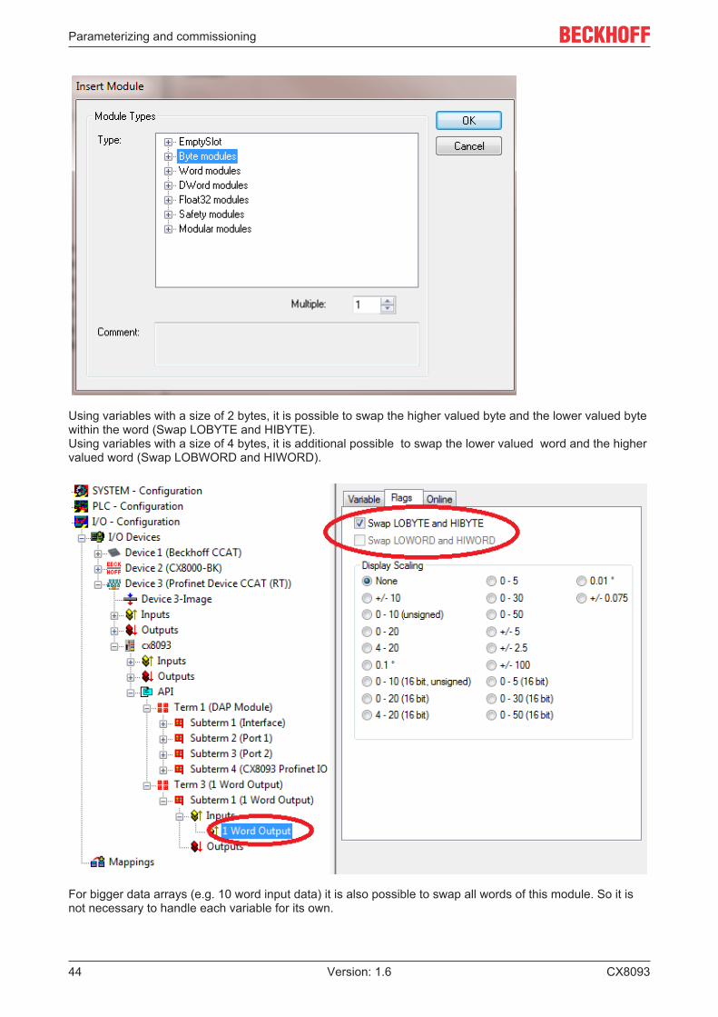
6.4.4 Process dataThe user is able to configure the process data that should be transmitted via PROFINET on his own.Several module types like byte, word, dword or real variables with different lengths are available. ViaGDSML file it is also possible to create modules and to use sub modules beneath them.
To create modules click at the tree on the API (Application Process Identifier) and insert the desiredmodules.
The GDSML file with miscellaneous PROFINET modules will be opened. TwinCAT uses the GDSML file thatis located in the folder TwinCAT\IO\PROFINET.
Parameterizing and commissioning
CX809344 Version: 1.6
Using variables with a size of 2 bytes, it is possible to swap the higher valued byte and the lower valued bytewithin the word (Swap LOBYTE and HIBYTE).Using variables with a size of 4 bytes, it is additional possible to swap the lower valued word and the highervalued word (Swap LOBWORD and HIWORD).
For bigger data arrays (e.g. 10 word input data) it is also possible to swap all words of this module. So it isnot necessary to handle each variable for its own.

Parameterizing and commissioning
CX8093 45Version: 1.6
Linking data without using the PLC
You can use the CX8093 without PLC functionality to link data from PROFINET to K-Bus or E-Bus. In thiscase you use the CX8093 as a configured bus coupler. Pay attention that always one task triggers thePROFINET and the K-Bus or E-Bus cycle at minimum. Without task the according interfaces are notexecuted.
If you want to link bits to a word, for example, activate the options Exclude other Devices and Continuous(Mapping).

Parameterizing and commissioning
CX809346 Version: 1.6
Note or pointerDoing this you should always link from the bigger to the smaller data type. For example link a wordto 16 Bit. Avoid to link bits to a byte or a word. For example if you link 8 bit to a word, afterwardsyou won't be able to retrace witch bits of the word are linked to the 8 bit.
6.4.5 Virtual Device InterfaceTable 3: Extracted nested table 0
Number of devices (process data) PROFINET cycle time5 (< 500 bytes of user data) 4 ms5 (> 500 bytes of user data) 8 ms10 (< 500 bytes of user data) 8 ms10 (> 500 bytes of user data) 16 ms20 (< 500 bytes of user data) 16 ms20 (> 500 bytes of user data) 32 ms25 (< 500 bytes of user data) 32 ms25 (> 500 bytes of user data) 64 ms
The virtual slave interface enables a second virtual device (slave) to be created on the same hardwareinterface. This enables the user to exchange more data with a PROFINET controller or to establish aconnection to a second PROFINET controller.
Since the ports X101 and X102 are switched via the hardware and only possess a real MAC address, that ofthe virtual PROFINET device is editable and the user himself is responsible for ensuring that these MACaddresses only occur once in his system. The IP address is assigned by the PROFINET controller andcannot be registered in the operating system. This means that non-PROFINET services such as ADS,CERHOST, etc. do not function over this IP address.

Parameterizing and commissioning
CX8093 47Version: 1.6
Pay attention to the system utilisation rate (to be observed only when using the vir-tual device interface)• Each PROFINET or Ethernet device that is connected via the switch of the CX8093 increases
the system utilisation rate.• The number of devices that run via the switch should not exceed 25 (the devices in the other di-
rection must also be counted)!
PROFINET name and IP address
The DIP switches cannot be used directly for the resolution of the name. However, the PLC can read theaddress switch and link the name via the Generate Station Name from Control function.
• No name• Name with DIP switch (only indirect)• Name by the System Manager• Name by the PLC program and System Manager
Device settings
"1" second, virtual PROFINET device"2" Editable MAC address, only the last byte is editable.
Generate Station Name from Control
With this an extension of the name can be assigned via the PLC program. The extension consists of a three-digit numerical value. To do this, link the PnIoBoxCtrl with the PLC program. The value must be registeredas a constant value and must be available when starting the PLC program. For example, the address of theswitch can be read and thus the name of the device formed with the function F_CX80xx_Address.
Example (ST):
Address:=16#FF AND INT_TO_WORD(F_CX80xx_Address(8093));PnIoBoxCtrl:=Address;

Parameterizing and commissioning
CX809348 Version: 1.6
Get Station Name from Tree
This means that the name of the PROFINET device will be taken from the System Manager tree.
Register PN IP settings not at the OS
Not possible with the virtual PROFINET interfaces.
PROFINET State
If you link the PnIoBoxState variable with your PLC program, you can monitor the state of the PROFINETcontroller with it. The state 0x0005 is the error-free state, i.e. the master is in data exchange with the device(i.e. the CX8093).
0x0001 = Device is in I/O exchange0x0002 = Device is blinking0x0004 = Provider State -> 0 = Stop, 1 = Run0x0008 = Problem Indicator -> 0 = OK, 1 = Error
No programming via the virtual PROFINET interfaceThe CX8093 cannot be programmed via the virtual IP address. The ADS functions or other non-PROFINET services are not supported by the virtual PROFINET interface.

Programming
CX8093 49Version: 1.6
7 Programming
7.1 Library for CX80xx
Download : https://infosys.beckhoff.com/content/1033/cx8093_hw/Resources/zip/1608565003.zip
7.2 Seconds UPS
7.2.1 Function blocks
FUNCTION_BLOCK FB_S_UPS_CX80xx
The FB_S_UPS function block can be used on the CX80xx with the seconds UPS in order to activate theseconds UPS from the PLC. This allows the persistent data to be saved and a quick shutdown to beperformed in the event of a power failure. If possible the default values of the INPUTs of the FB_S_UPSshould be retained.
NOTELoss of dataThe seconds UPS can be used only for a few seconds in the event of a power failure in order, for example,to save persistent data. The data must be saved in the fast persistent mode "SPDM_2PASS", even thoughthis can lead to real-time violations. Sufficient router memory must be configured for the storage of the per-sistent data!
The second UPS does not have sufficient capacity for bridging power failures. Saving can take place only onMicro SD cards.
A QuickShutdown is performed automatically in the eSUPS_WrPersistData_Shutdown mode (standardsetting) after the storage of the persistent data.
In the eSUPS_WrPersistData_NoShutdown mode only the persistent data are saved, no QuickShutdown isperformed.
In the eSUPS_ImmediateShutdown mode a QuickShutdown is executed immediately without saving data.
In the eSUPS_CheckPowerStatus mode only a check is performed as to whether a power failure hasoccurred. If this is the case, the module only switches back to the PowerOK state after the expiry oftRecoverTime (10s).
Independent of the mode and thus independent of the saving or the shutting down of the controller, the UPSswitches the main board off after the capacitors have discharged, even if the voltage has returned in themeantime.

Programming
CX809350 Version: 1.6
NOTECaution when using files:If other applications or the PLC keep other files open or write to them, this can lead to faulty files if the UPSswitches off the controller.
VAR_INPUTVAR_INPUT sNetID : T_AmsNetId := ''; (* '' = local netid *) iPLCPort : UINT := AMSPORT_R0_PLC_RTS1; (* PLC Runtime System for writing persistent data *) iUPSPort : UINT := 16#4A8; (* Port for reading Power State of UPS, dafault 16#4A8 *) tTimeout : TIME := DEFAULT_ADS_TIMEOUT; (* ADS Timeout *) eUpsMode : E_S_UPS_Mode := eSUPS_WrPersistData_Shutdown; (* UPS mode (w/wo writing persistent data, w/wo shutdown) *) ePersistentMode : E_PersistentMode := SPDM_2PASS; (* mode for writing persistent data *) tRecoverTime : TIME := T#10s; (* ON time to recover from short power failure in mode eSUPS_WrPersistData_NoShutdown/eSUPS_CheckPowerStatus *)END_VAR
E_S_UPS_Mode
sNetID : AmsNetID of the controller.
iPLCPort : Port number of the PLC runtime system (AMSPORT_R0_PLC_RTS1 = 801,AMSPORT_R0_PLC_RTS2 = 811, AMSPORT_R0_PLC_RTS3 = 821, AMSPORT_R0_PLC_RTS4 = 831).
iUPSPort : Port number via which the UPS status is read (standard value is 16#4A8).
tTimeout : Timeout for the execution of the QuickShutdown.
eUpsMode : The eUpsMode defines whether persistent data are to be written and whether aQuickShutdown is to be performed. Standard value is eSUPS_WrPersistData_Shutdown, i.e. with writing of thepersistent data and then QuickShutdown. See E_S_UPS_Mode.
ePersistentMode : Mode for the writing of the persistent data. Standard value is SPDM_2PASS. SPDM_2PASS, all persistent data are saved at once, which can lead to the cycletime being exceeded. SPDM_VAR_BOOST, here, each persistent variable is written separately; if there isa large amount of persistent data this can accordingly take many cycles. This is not recommended as somedata may be lost if the time of the seconds UPS is not sufficient.
tRecoverTime : Time after which the UPS reverts to the PowerOK status in the case of UPS modeswithout shutdown. The tRecoverTime must be somewhat longer than the maximum holding time of theUPS, since the UPS switches off even when the voltage returns.
VAR_OUTPUTVAR_OUTPUT bPowerFailDetect : BOOL; (* TRUE while powerfailure is detected *) eState : E_S_UPS_State; (* current ups state *)END_VAR
E_S_UPS_State
bPowerFailDetect : True during the power failure; False if the supply voltage is present.
eState : Internal state of the function block, for values see E_S_UPS_State.
VAR_GLOBALVAR_GLOBAL eGlobalSUpsState : E_S_UPS_State; (* current ups state *)END_VAR
E_S_UPS_State

Programming
CX8093 51Version: 1.6
eGlobalUpsState : Internal state of the function block as a global copy of the VAR_OUTPUT eState; forvalues see E_S_UPS_State.
Prerequisites
Development environ-ment
Target platform Hardware PLC libraries to belinked
TwinCAT v2.11.0 build2220 or higher (R3)
ARM Seconds UPS TcSystemCX80xx.lib

Programming
CX809352 Version: 1.6
7.2.2 Data types
TYPE E_S_UPS_ModeeSUPS_WrPersistData_Shutdown: Schreiben der Persistenten Daten und dann QuickShutdowneSUPS_WrPersistData_NoShutdown: Nur Schreiben der Persistenten Daten (kein QuickShutdown)eSUPS_ImmediateShutdown: Nur QuickShutdown (kein Schreiben der Persistenten Daten)eSUPS_CheckPowerStatus: Nur Status ermitteln (weder Schreiben der Persistenten Daten noch QuickShutdown)
Prerequisites
Development environ-ment
Target platform Hardware PLC libraries to belinked
TwinCAT v2.11.0 build2220 or higher (R3)
ARM Seconds UPS TcSystemCX80xx.lib
TYPE E_S_UPS_StateeSUPS_PowerOK: in allen Modi: Versorgungsspannung ist OK
eSUPS_PowerFailure: in allen Modi: Versorgungsspannung fehlerhaft (steht nur einen Zyklus an)
eSUPS_WritePersistentData: im Modus eSUPS_WrPersistData_Shutdown: Schreiben der Persistenten Daten ist aktiv im Modus eSUPS_WrPersistData_NoShutdown: Schreiben der Persistenten Daten ist aktiv
eSUPS_QuickShutdown: im Modus eSUPS_WrPersistData_Shutdown: QuickShutdown ist aktiv im Modus eSUPS_ImmediateShutdown: QuickShutdown ist aktiv
eSUPS_WaitForRecover: im Modus eSUPS_WrPersistData_NoShutdown: Warten auf Wiederkehr der Spannung im Modus eSUPS_CheckPowerStatus: Warten auf Wiederkehr der Spannung
eSUPS_WaitForPowerOFF: im Modus eSUPS_WrPersistData_Shutdown: Warten auf das Abschalten durch die USV im Modus eSUPS_ImmediateShutdown: Warten auf das Abschalten durch die USV
Prerequisites
Development environ-ment
Target platform Hardware PLC libraries to belinked
TwinCAT v2.11.0 build2220 or higher (R3)
ARM Seconds UPS TcSystemCX80xx.lib

Programming
CX8093 53Version: 1.6
7.3 Diagnostics
7.3.1 FUNCTION F_CX80xx_ADDRESSWith this function the address selection switch or the DIP switch of the CX80xx device can be read out.Here, for example, you can activate different parts of the program depending on the address by reading theswitch position.
VAR_INPUTVAR_INPUT iCX_Typ : INT; END_VAR
iCX_Typ : The CX type used is entered here - just the number without the designation CX: forexample, CX8031 is then entered as 8031.
VAR_OUTPUTF_CX80xx_ADDRESS : INT;
F_CX80xx_ADDRESS : -1, non-implemented CX, address of the switch
Prerequisites
Development environ-ment
Target platform Hardware PLC libraries to belinked
TwinCAT v2.11.0 build2220 or higher (R3)
ARM CX80xx TcSystemCX80xx.lib

Ethernet
CX809354 Version: 1.6
8 Ethernet
8.1 System introduction
8.1.1 EthernetEthernet was originally developed by DEC, Intel and XEROX (as the "DIX" standard) for passing databetween office devices. The term nowadays generally refers to the IEEE 802.3 CSMA/CD specification,published in 1985. Because of the high acceptance around the world this technology is available everywhereand is very economical. This means that it is easy to make connections to existing networks.
There are now a number of quite different transmission media: coaxial cable (10Base5), optical fiber(10BaseF) or twisted pairs (10BaseT) with screen (STP) or without screen (UTP). A variety of topologiessuch as ring, line or star can be constructed with Ethernet.
Ethernet transmits Ethernet packets from a sender to one or more receivers. This transmission takes placewithout acknowledgement, and without the repetition of lost packets. To achieve reliable datacommunication, there are protocols, such as TCP/IP, that can run on top of Ethernet.
MAC-ID
The sender and receiver of Ethernet packets are addressed by means of the MAC-ID. The MAC-ID is a 6byte identification code unique to every Ethernet device in the world. The MAC-ID consists of two parts. Thefirst part (i.e. the first 3 bytes) is a manufacturer identifier. The identifier for Beckhoff is 00 01 05. The next 3bytes are assigned by the manufacturer and implement a unique serial number. The MAC-ID can, forexample, be used for the BootP protocol in order to set the TCP/IP number. This involves sending atelegram containing the information such as the name or the TCP/IP number to the corresponding node. Youcan read the MAC-ID with the KS2000 configuration software.
The Internet Protocol (IP)
The internet protocol (IP) forms the basis of this data communication. IP transports data packets from onedevice to another; the devices can be in the same network, or in different networks. IP here looks after theaddress management (finding and assigning MAC-IDs), segmentation and routing. Like the Ethernetprotocol, IP does not guarantee that the data is transported - data packets can be lost, or their sequence canbe changed.
TCP/IP was developed to provide standardized, reliable data exchange between any number of differentnetworks. TCP/IP is thus substantially independent of the hardware or software being used. Although theterm is often used as if it were a single concept, a number of protocols are layered together: e.g. IP, TCP,UDP, ARP and ICMP.
Transmission Control Protocol (TCP)
The Transmission Control Protocol (TCP) which runs on top of IP is a connection-oriented transport protocol.It includes error detection and error handling mechanisms. Lost telegrams are repeated.
User Datagram Protocol (UDP)
UDP is connectionless transport protocol. It provides no control mechanism when exchanging data betweensender and receiver. This results in a higher processing speed than, for example, TCP. Checking whether ornot the telegram has arrived must be carried out by the higher-level protocol.

Ethernet
CX8093 55Version: 1.6
Fig. 2: Ethernet protocol
Protocols running on top of TCP/IP and UDP/IP
The following protocols can run on top of TCP/IP or UDP:
• ADS• ModbusTCP
Both of these protocols are implemented in parallel on the Bus Coupler, so that no configuration is needed toactivate the protocols.
ADS can be used on top of either TCP or UDP, but ModbusTCP is always based on TCP/IP.

Ethernet
CX809356 Version: 1.6
8.1.2 Topology example
CX8093

Ethernet
CX8093 57Version: 1.6
8.2 PROFINETPROFINET is the open Industrial Ethernet-standard of the PNO (PROFIBUS User Organisation). PROFINETIO describes the exchange of data between controllers and field devices in several real-time classes: RT(software-based real-time) and IRT (hardware-supported isochronous real-time). In addition, further Ethernettraffic can be transmitted in the NRT (non-real-time) time slot of the PROFINET cycle. RT can be networkedwith commercially available switches; switches with corresponding hardware support are required for IRT.

Ethernet
CX809358 Version: 1.6
Requirements
Components CommentEmbedded PCsCX8093 Embedded PC with PROFINET RT Device fieldbus
interfaceCX50xx-M930 Embedded PC with optional
PROFINET RT Controller interfaceCX50xx-B930 Embedded PC with optional PROFINET RT Device
interfaceEtherCAT terminalsEL6631 PROFINET IO controller
EL6631-0010 PROFINET IO device
EL6632 PROFINET-IRT controllerBus CouplerBK9053 PROFINET "Compact" Bus Coupler for Bus
TerminalsBK9103 PROFINET Bus Coupler for Bus Terminals
EK9300 PROFINET Bus Coupler for EtherCAT TerminalsFieldbus BoxIL230x-B903 PROFINET Coupler BoxPC Fieldbus cards FC900x PCI-Ethernet card for all Ethernet
(IEEE 802.3)-based protocols FC9x51 Mini PCI-Ethernet card for all Ethernet
(IEEE 802.3)-based protocolsTwinCAT TwinCAT PROFINET IO Controller TwinCAT as PROFINET master
TwinCAT PROFINET IO Device TwinCAT as PROFINET slave

Ethernet
CX8093 59Version: 1.6
8.3 ADS-Communication
Communication
The ADS protocol (ADS: Automation Device Specification) is a transport layer within the TwinCAT system. Itwas developed for data exchange between the different software modules, for instance the communicationbetween the NC and the PLC. This protocol enables communication with other tools from any point withinthe TwinCAT. If communication with other PCs or devices is required, the ADS protocol can use TCP/IP as abasis. Within a networked system it is thus possible to reach all data from any point.
The ADS protocol runs on top of the TCP/IP or UDP/IP protocols. It allows the user within the Beckhoffsystem to use almost any connecting route to communicate with all the connected devices and toparameterize them. Outside the Beckhoff system a variety of methods are available to exchange data withother software tools.
Software interfaces
ADS-OCXThe ADS-OCX is an Active-X component. It offers a standard interface to, for instance, Visual Basic, Delphi,etc.
ADS-DLLYou can link the ADS-DLL (DLL: Dynamic Link Library) into your C program.
OPCThe OPC interface is a standardized interface for communication used in automation engineering. Beckhoffoffer an OPC server for this purpose.
Protocol
The ADS functions provide a method for accessing the Bus Coupler information directly from the PC. ADSfunction blocks can be used in TwinCAT PLC Control for this. The function blocks are contained in thePLCSystem.lib library. It is also equally possible to call the ADS functions from AdsOCX, ADSDLL or OPC.

Ethernet
CX809360 Version: 1.6
AMSNetIDThe AMSNetID provides a reference to the device that is to be addressed. This is taken from the MACaddress of the first Ethernet port (X001) and is printed on the side of the CX80xx. For the AMSNetID thebytes 3 to 6 plus ".1.1" are typically used.Example:MAC address 00-01-05-01-02-03 AMSNetID 5.1.2.3.1.1
Port numberThe port number distinguishes sub-elements in the connected device.Port 801: local process data PLC runtime 1
Index groupThe index group distinguishes different data within a port.
Index offsetIndicates the offset, the byte from which reading or writing is to start.
LenGives the length of the data, in bytes, that is to be read or written.
TCP port numberThe TCP port number for the ADS protocol is 48898 or 0xBF02.

Error handling and diagosis
CX8093 61Version: 1.6
9 Error handling and diagosis
9.1 LED displays
Ethernet interface X001
Interface X001 Ethernet (CX8093) MeaningLED green on Link presentLED yellow flashing Activity
Ethernet interface X101/102
Interface X001/X002 Ethernet (CX8093) MeaningLED green on Link available/activityLED yellow is not used -
LED coupler
Labelling Meaning Colour MeaningRUN Indicates the status of the
couplerred TwinCAT is in "stop"
modeGreen TwinCAT is in "run" modeBlue(If red DIP switch 1 is setto on when starting thecoupler)
TwinCAT is in "config"mode

Error handling and diagosis
CX809362 Version: 1.6
LED PN * PROFINET Status Meaninggreen red
Power On off 200 ms flashing Start-up phaseNo name 200 ms flashing off no PROFINET nameNo IP 1 sec off, 200 ms on off No IP addressRun on off OK
LED DIAG * PROFINET diagnosis Meaninggreen red
Flashing, PN controlleridentification
500 ms 500 ms The PN controller istransmitting anidentification signal
No AR established off 200 ms flashing The establishment of aconnection with thecontroller has not beencompleted
Device is in IO exchangeError display of OutputsCR is set to moduledifferences
1 s off 200, ms on off Problem withestablishment of aconnection or nominal andactual configuration differ
Device is in IO exchangebut provider is in stop
200 ms off Coupler is in dataexchange, but PLC is instop
Device is in IO exchange on off OK
* ) If a virtual PROFINET device has been projected, this is also signalled by the LEDs in the event of anerror. The real device always has the higher priority; if it is OK the status of the virtual device is displayed.
LED power supply terminal
Operation with E-bus terminals Operation with K-bus terminals
Display LED Description Meaning1 Us 24 V (top left, 1st row) CX80xx supply voltage connected to -24 V2 Up 24 V (top right, 1st row) Power contacts supply voltage connected to -24 V3 L/A (left centre, 2nd row) EtherCAT LED flashing green: EtherCAT
communication activeconnected to E-bus / no data trafficnot connected to E-bus
4 K-BUS RUN (right centre, 2ndrow)
K-bus LED RUN Lights up green: K-bus running,everything OK
6 K-BUS ERR (bottom right, 3rdrow)
K-bus LED ERR Lights up red: K-bus error - see K-bus error code

Error handling and diagosis
CX8093 63Version: 1.6
K-bus error code
Error code Error code argument Description RemedyPersistent, continuousflashing
EMC problems • Check power supply forundervoltage orovervoltage peaks
• Implement EMCmeasures
• If a K-bus error ispresent, it can belocalised by a restart ofthe coupler (byswitching it off and thenon again)
3 pulses 0 K-bus command error • No Bus Terminalinserted
• One of the BusTerminals is defective;halve the number ofBus Terminals attachedand check whether theerror is still present withthe remaining BusTerminals. Repeat untilthe defective BusTerminal is located.
4 pulses 0 K-Bus data error, breakbehind the Bus Coupler
Check whether the n+1Bus Terminal is correctlyconnected; replace ifnecessary.
n Break behind BusTerminal n
Check whether the BusEnd Terminal 9010 isconnected.
5 pulses n K-Bus error in registercommunication with BusTerminal n
Exchange the nth busterminal
6 pulses 0 Error at initialisation Exchange Bus Coupler1 Internal data error Perform a hardware reset
on the Bus Coupler(switch off and on again)
8 Internal data error Perform a hardware reseton the Bus Coupler(switch off and on again)
7 pulses 0 Process data lengths donot correspond to theconfiguration
Check the Bus Terminalsfor the configured BusTerminals
1..n K-bus reset failed Check the Bus Terminals

Appendix
CX809364 Version: 1.6
10 Appendix
10.1 First stepsThe following components are necessary for the first steps
• PC with TwinCAT 2.11 R3• Ethernet cable• Power supply (24 VDC), cabling material• a KL2xxx or an EL2xxx, digital output terminal, end terminal
Required TwinCAT versionTwinCAT 2.11 R3 is required for the programming of the CX80xx series. Older TwinCAT versionsand TwinCAT 3.x are not supported!
1. Connect K-bus or E-bus terminals to the controller.
2. Connect voltage to the CX80xx (see power supply [} 21]).
3. Connect Ethernet (CX80xx X001) to your network or a direct connection to your PC (make sure in thecase of a peer-to-peer connection that the IP addressing in your PC is set to DHCP).
4. Wait a while, approx. 1 to 2 minutes; either the CX80xx will be assigned an address by the DHCP server(usually fast) or, if it does not find a DHCP server, it uses a local IP address.
5. Switch on TC on the PC in Config Mode (TwinCAT icon blue) and start the System Manager
6. In the System Manager, click on the PC symbol (Choose Target System) or press >F8<
7. The following dialog box opens; click on Search (Ethernet).

Appendix
CX8093 65Version: 1.6
8. Select Option 1 if you have addressed via DHCP or Option 2 in case of DHCP or local IP address. Thenclick on "Broadcast search".
Your network is scanned for Beckhoff controllers. If none is found, this means that the DHCP of the controlleris not yet completed or the network settings on your PC are incorrect. A network cable that has not beenconnected can naturally also be the cause, but this should not be the case if point 3 has been done.

Appendix
CX809366 Version: 1.6
9. The host name is composed by default of "CX" and the last 3 bytes of the MAC address. You can find theMAC address on the side of the CX80xx. The MAC address is always 6 bytes long and the first three bytesare the vendor ID, which is always 00 01 05 in the case of Beckhoff devices.
An "X" next to Connected means that the CX is already known in the system and can be used. To make itknown, click in the list on the CX with which you want to connect and then click on "Add route". An inputmask opens with "User name" and "Password". By default there is no password, simply confirm by clickingon OK. Afterwards the "X" should appear next to connected.
10. Next, the CX should appear in the list of the devices; select it and confirm by clicking on OK.
11. Check whether the connection is there. In the System Manager in the bottom right-hand corner. It mustbe blue or green and may not be yellow.
12. If the setting is green, switch the CX to Config Mode with "Shift F4" or click on the blue TC icon in theSystem Manager. The System Manager now asks you whether you really want to switch to Config Mode;confirm by clicking on OK.
13. The setting at the bottom right must now change to blue and the TC LED on the CX80xx must now alsolight up blue.
14. Now click on I/O Devices and then on Scan Devices...
15. A message appears, informing you that not everything will be automatically detected.
16. The CCAT interface is usually found (CX8090) or the corresponding fieldbus interface (other CX80xxdevices) and either a K-bus interface or an EtherCAT interface, depending now on which terminals you haveconnected to the CX. The CCAT interface must be present in the System Manager file and may not bedeleted. If an error message should appear when scanning, check the revision level of your TwinCATversion and perform an update if necessary.

Appendix
CX8093 67Version: 1.6
17. Now we come to the programming. To do this, open the PLC Control and select File -> New. The PLCControl asks you for the target system. Select CX (ARM). Afterwards it asks you for the function block; setthe ST language (structured text). Now write a small program...
Translate the program. If it is error free (a warning must come, that it is OK) save the project under anarbitrary name, translate it again and save it once again.
18: Switch once again to the System Manager and add the program under PLC - Configuration. AFileName.typ file is sought.
19: Now open the project, then the task and then outputs, in which there must be a variable MAIN.bToggle.You can link this with the hardware. To do this, click on "Linked to...".

Appendix
CX809368 Version: 1.6
Select a digital output. Now you can download the configuration to the CX and switch the CX to Run Mode.To do this, click on the ‘cube’ or press Ctrl + Shift + F4. The TC LED on the CX must then light up green.
20. Switch back to PLC Control, go to "Online/Selection of the target system", select the correct CX, click onit and select runtime system 1. Now "Online/login" again (F11) transfer the PLC program, then "Online/Start" (F5). The LED on your terminal must now flash.
21. As a final step Online/Generate a boot project. This completes the project and your first program isstored on the CX.
Congratulations, the foundations have now been laid and are ready to be built on. We wish you everysuccess!

Appendix
CX8093 69Version: 1.6
10.2 Image UpdateThere are two different possibilities to update the image of the CX80xx.
Prerequisites• Please make sure before the update that your CX80xx supports the image that you want to load.• When updating the image, please first update all existing files and only then copy the new image.
Always copy all files and directories in order to update a CX80xx.
Update via USB
CAUTIONUSB port as ignition source in potentially explosive atmospheresGases or dusts can be ignited by a spark discharge when the USB port is used.Switch off the power supply and wait until the 1-second UPS has discharged. Ensure that there is no explo-sive atmosphere before you use the USB port.
A USB cable is required for this!
• Switch off the CX80xx
• Set red Dip switch (under the flap) DIP 1 to ON• Switch on the CX• Connect the PC with USB• Delete all files (we recommend that you backup all files first), no formatting

Appendix
CX809370 Version: 1.6
• Wait until copying has finished, then remove the USB cable• Switch DIP switch 1 to OFF• Switch off the CX80xx• Switch on the CX80xx; it may take a little longer the first time
Update the MicroSD card
A MicroSD card reader is required for this!
• Remove the MicroSD card from the switched-off CX device.• Insert the MicroSD card into the reader• Delete all files (we recommend that you backup all files first), no formatting• Load the new image• Wait until copying has finished, then remove the MicroSD card• Insert the MicroSD card into the SD slot of the switched-off CX again• Now switch on the CX again; it may take a little longer the first time

Appendix
CX8093 71Version: 1.6
10.3 Certification
10.3.1 ExThe CX8xxx Embedded PCs, which are certified for use in potentially explosive atmospheres, have thefollowing IDs:
II 3 G Ex nA IIC T4 GcII 3 D Ex tc IIIC T135 ºC DcDEKRA 16ATEX0052 XTa: 0°C-55°C
Serial number
The name plate of the CX8xxx Embedded PCs shows a consecutive serial number, a hardware version anda date of manufacture:
Legend:
n: Serial number, consecutive numberh: Hardware version, ascending numberdd: Production daymm: Production monthyyyy: Production year

Appendix
CX809372 Version: 1.6
10.3.2 FCC
FCC Approvals for the United States of America
FCC: Federal Communications Commission Radio Frequency Interference Statement
This equipment has been tested and found to comply with the limits for a Class A digital device, pursuant toPart 15 of the FCC Rules. These limits are designed to provide reasonable protection against harmfulinterference when the equipment is operated in a commercial environment. This equipment generates, uses,and can radiate radio frequency energy and, if not installed and used in accordance with the instructionmanual, may cause harmful interference to radio communications. Operation of this equipment in aresidential area is likely to cause harmful interference in which case the user will be required to correct theinterference at his own expense.
FCC Approval for Canada
FCC: Canadian Notice
This equipment does not exceed the Class A limits for radiated emissions as described in the RadioInterference Regulations of the Canadian Department of Communications.
10.3.3 ULThe UL-certified CX8xxx Embedded PCs have the following IDs:
Compliance with UL requirements:
Compliance with the following UL requirements is required, in order to guarantee the UL certification for theCX8xxx Embedded PC:
• The Embedded PCs must not be connected to unlimited voltage sources.• Embedded PCs may only be supplied from a 24 V DV voltage source. The voltage source must be
insulated and protected with a fuse of maximum 4 A (corresponding to UL248).• Or the power supply must originate from a voltage source that corresponds to NEC class 2. An NEC
class 2 voltage source must not be connected in series or parallel with another NEC class 2 voltagesource.

Appendix
CX8093 73Version: 1.6
10.4 Support and ServiceBeckhoff and their partners around the world offer comprehensive support and service, making available fastand competent assistance with all questions related to Beckhoff products and system solutions.
Beckhoff's branch offices and representatives
Please contact your Beckhoff branch office or representative for local support and service on Beckhoffproducts!
The addresses of Beckhoff's branch offices and representatives round the world can be found on her internetpages: https://www.beckhoff.com
You will also find further documentation for Beckhoff components there.
Beckhoff Support
Support offers you comprehensive technical assistance, helping you not only with the application ofindividual Beckhoff products, but also with other, wide-ranging services:
• support• design, programming and commissioning of complex automation systems• and extensive training program for Beckhoff system components
Hotline: +49 5246 963 157Fax: +49 5246 963 9157e-mail: [email protected]
Beckhoff Service
The Beckhoff Service Center supports you in all matters of after-sales service:
• on-site service• repair service• spare parts service• hotline service
Hotline: +49 5246 963 460Fax: +49 5246 963 479e-mail: [email protected]
Beckhoff Headquarters
Beckhoff Automation GmbH & Co. KG
Huelshorstweg 2033415 VerlGermany
Phone: +49 5246 963 0Fax: +49 5246 963 198e-mail: [email protected]: https://www.beckhoff.com


Beckhoff Automation GmbH & Co. KGHülshorstweg 2033415 VerlGermanyPhone: +49 5246 [email protected]
More Information: www.beckhoff.com/CX8093